

PRO PX2000
®
Users Manual
ENGLISH
Version 1.2 May 2001
ULTRAPATCH
DATA-MANFULL_PX2000_ENG_Rev. D.p65 10.05.01, 14:561
www.behringer.com
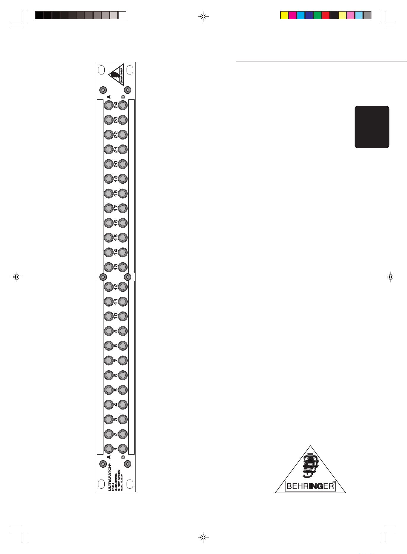
ULTRAPATCH PRO PX2000
Welcome to BEHRINGER!
Thank you very much for expressing your confidence in BEHRINGER products by purchasing the ULTRAPATCH PRO
PX2000.
A patchbay allows to patch the audio signals of most components in your studio from a central point and send them
to other units, which makes your entire cabling better structured and is indispensable for professional work. If you
want to use your studio as effectively as possible then it is preferable to use a complete patchbay wiring scheme, but
even less sophisticated patchbay solutions will benefit smaller studio configurations.
1. PATCHBAY CONFIGURATION
The majority of commercially available patchbays include two rows with 24 phone jacks each in a 19" 1 HU rack panel.
On the rear, either a corresponding number of phone jacks or contacts for soldering signal leads can be found. Each
group of four of these phone jacks forms one module. The configuration of some patchbays can be changed by
inserting jumpers or turning individual modules.
With the BEHRINGER ULTRAPATCH PRO PX2000 you own an easy-to-use 24-patchbay offering phone jacks throughout,
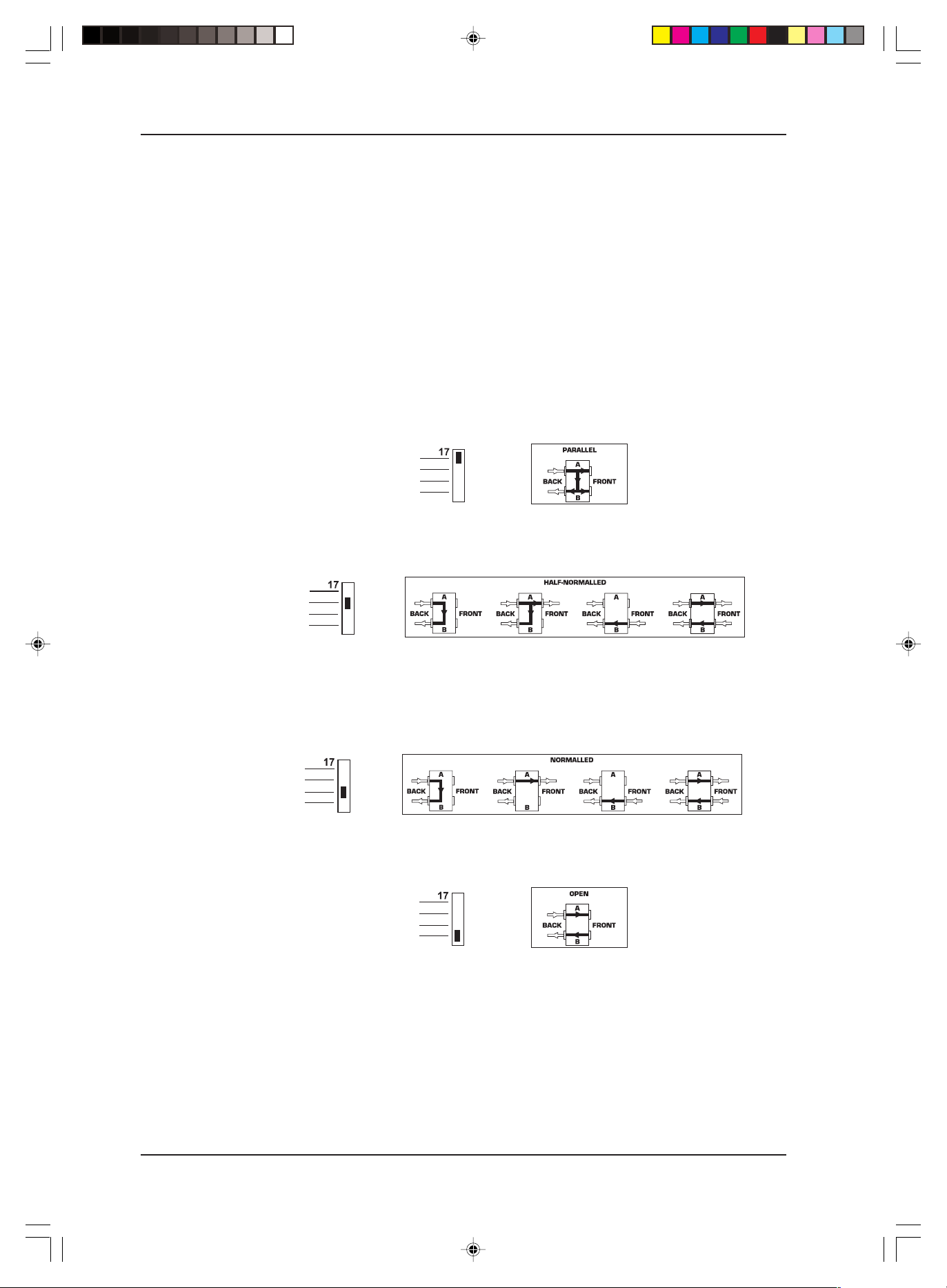
which can be operated in four different modes simply by setting a switch on the upper panel (example: module 17):
1.1 Parallel
In this mode, all terminals of one module are interconnected. This configuration doesnt make sense at first glance
but is used to split up and send one audio signal (e.g. aux send) to several destinations (e.g. effects devices).
1.2 Half-normalled
In this configuration, the contacts of the two jacks on the rear are interconnected. When you insert a plug into the upper
front jack, the signal routed through the rear path is not interrupted. Only when the lower front jack is used will the rearpanel route be split up, so that the two upper and the two lower phone jacks are connected to one another. This
configuration is called input break and is used mainly for insert paths. So you can easily patch the signal from a
mixing console channel at the patchbay without interrupting the signal flow in the channel.
1.3 Normalled
Here, and in contrast to the half-normalled setup, the signal route of the rear phone jacks is interrupted when you
insert a plug both into the upper and lower front jacks.
1.4 Open
This mode is used to connect devices such as sound modules or CD players having no inputs of their own. This
saves space, as you can route the left and right outputs to one module (left - top; right - bottom) or patch two devices
to one module (top and bottom). Effects devices and 2-tracks can be configured this way, so the inputs and outputs
are positioned on top of each other.
Basically, the inputs are routed to the bottom and the outputs to the top rear-wall connectors. Avoid routing digital
signals over a patchbay as the pulse signal used for the transmission of such signals causes heavy interference in
analog signals. Additionally, normal patchbays change the impedance of the digital cable route, which causes
interference in the digital path. Use the BEHRINGER ULTRAMATCH SRC2496 specifically designed for this and other
digital signal-related functions.
Microphone inputs operate at a level several orders of magnitude lower than line levels (+4 dBu or -10 dBV). Therefore, they should never be routed via a patchbay. In any case, patching in a field with 48 V DC (phantom power) flying
2
DATA-MANFULL_PX2000_ENG_Rev. D.p65 10.05.01, 14:562

ULTRAPATCH PRO PX2000
about is to be avoided at all costs. It is best to plug mics directly into the mixing console or via special XLR-type wall
boxes connected to the mic inputs of the console by good-quality balanced multicore cables (2-cond. + shield).
2. PATCHBAY ORGANIZATION
Let us give you an example configuration that shows how you can most effectively use your patchbays. We assume
you own a mixing console with 16 mic/line inputs plus inserts, 8 direct outputs, 8 subgroups with 4 inserts, 4 aux
paths with 2 stereo returns and one stereo master output including insert jacks. Added to this we have an 8-track
recorder (digital or analog), a few pieces of outboard equipment (FX, dynamics & EQs), a CD player, tape deck, HiFi
system and a headphones amp:
1
2
3
4
In the first eight modules of patchbay 1 the subgroup outputs are directly connected to the corresponding multitrack
inputs. In addition to that it is also possible to record the signals coming from a subgroup on a different track of the
multitrack. To save space and provide a clearly structured configuration, the direct outputs are connected both to the
top and bottom jacks. Modules 17 & 18 are the stereo master output, which is half-normalled and thus allows for
recording both to the DAT recorder and the tape deck, simply by patching it accordingly. Modules 19 & 20 (tape deck)
are open, because it does not make sense connecting the inputs and outputs of the tape deck. 21 & 22 are normalled
and route the DAT recorder outputs to the 2 TRK-ins of the mixing console. So it always is possible to control the
recorded data on the 2-track from the mixing console. The CD player and the HiFi system are connected to modules
23 & 24, which are open, because they only serve as a source.
In patchbay
monitor inputs if the console has a separate monitor section). MIDI devices such as samplers, expanders,
keyboards, etc. are usually set up in every corner of the room. To make the cabling better structured we route these
units to modules 9 through 16. This allows further workmanship of the MIDI devices at the mixing console. Modules
17 through 20 are normalled and have the FX inputs and the aux sends connected, 21 through 24 are also normalled
and are patched to the two stereo aux returns with the FX outputs.
In patchbay
have an additional route for the channel signals. The same applies to the insert paths of the subgroups and the
master output. The headphones amp is connected to 23 & 24, which are normalled and connected to the control room
outputs of the mixing console. Of course, you can also use pre-fader aux paths for the headphones mix.
DATA-MANFULL_PX2000_ENG_Rev. D.p65 10.05.01, 14:563
2
3
the first 16 modules are normalled (1 through 8 IN could also be used to connect the corresponding
, modules 1 through 16 are for the channel insert. These modules are half-normalled, so that you
3

ULTRAPATCH PRO PX2000
Patchbay 4 manages the dynamics and frequency-processing devices in an open configuration (modules 1
through 16). Multigates and compressors should be used here, in particular. Modules 17 through 24 are used to
provide a parallel split, i.e. two modules are patched to each other on the rear with one patch cord, so that you can
split up a signal applied on the front panel to several destinations. These modules have a parallel configuration.
It should be noted that patchbays should be placed one below the other in such a way that the patch cords wont hang
all over the patchbays. In our example you dont have to span great distances, for instance, to patch the dynamics and
EQs to the insert paths.
3. LOOMING PROBLEMS
Loom wiring is an art unto itself, and it is worth taking time out to get it right. First off, it is important to avoid earth loops
(a looped wire acts an aerial, picking up hum and electromagnetic radiation). Think of a tree. Every part of that tree is
connected to every other part, but only by one route. Thats how the total earth picture for your entire studio should look.
Dont take the earth off your power cable plug to reduce audible 50 Hz mains hum. Rather you should be looking at
disconnecting the signal screen somewhere (one or several audio cables).
It is good practice to ensure that all screens are commoned at the patchbay, in which case all unearthed equipment
would pick up earth from this point via a single screen (more than one route = an earth loop), while mains-earthed
equipment would have all screens cut at the equipment end.
Some quality equipment has an independent signal and mains earth. In this case at least one screen should carry
earth to the equipment. Sometimes the only way to find out is suck and see.
Take care to ensure that using the patchbay does not disturb the studios earth architecture. Always use short as
possible patch leads with the screen connected at both ends.
Having designed mains hum out of the system, make up your cable looms from the patchbays outwards, and use
cable ties, flexible sheaths, multicores, etc. to keep the back of your racks tidy.
4. SPECIFICATIONS
Dimensions
Width 482.6 mm (19")
Height 1 HU
Depth 93 mm
Weight ca. 1.8 kg
5. WARRANTY
§ 1 WARRANTY CARD/ONLINE REGISTRATION
To be protected by the extended warranty, the buyer must complete and return the enclosed
warranty card within 14 days of the date of purchase to BEHRINGER Spezielle Studiotechnik
GmbH, in accordance with the conditions stipulated in § 3. Failure to return the card in due time
(date as per postmark) will void any extended warranty claims.
Based on the conditions herein, the buyer may also choose to use the online registration option
via the Internet (www.behringer.com or www.behringer.de).
§ 2 WARRANTY
1. BEHRINGER (BEHRINGER Spezielle Studiotechnik GmbH including all BEHRINGER subsidiaries listed on the enclosed page, except BEHRINGER Japan) warrants the mechanical and
electronic components of this product to be free of defects in material and workmanship for a
period of one (1) year from the original date of purchase, in accordance with the warranty regulations described below. If the product shows any defects within the specified warranty period that
are not due to normal wear and tear and/or improper handling by the user, BEHRINGER shall, at
its sole discretion, either repair or replace the product.
2. If the warranty claim proves to be justified, the product will be returned to the user freight prepaid.
3. Warranty claims other than those indicated above are expressly excluded.
§ 3 RETURN AUTHORIZATION NUMBER
1. To obtain warranty service, the buyer (or his authorized dealer) must call BEHRINGER (see
enclosed list) during normal business hours BEFORE returning the product. All inquiries must be
accompanied by a description of the problem. BEHRINGER will then issue a return authorization
number.
2. Subsequently, the product must be returned in its original shipping carton, together with the
return authorization number to the address indicated by BEHRINGER.
3. Shipments without freight prepaid will not be accepted.
§ 4 WARRANTY REGULATIONS
1. Warranty services will be furnished only if the product is accompanied by a copy of the original
retail dealers invoice. Any product deemed eligible for repair or replacement by BEHRINGER
under the terms of this warranty will be repaired or replaced within 30 days of receipt of the product
at BEHRINGER.
2. If the product needs to be modified or adapted in order to comply with applicable technical or
safety standards on a national or local level, in any country which is not the country for which the
product was originally developed and manufactured, this modification/adaptation shall not be
considered a defect in materials or workmanship. The warranty does not cover any such modification/adaptation, irrespective of whether it was carried out properly or not. Under the terms of this
The information contained in this manual is subject to change without notice. No part of this manual may be reproduced or transmitted in any form or by any means, electronic or mechanical,
including photocopying and recording of any kind, for any purpose, without the express written permission of BEHRINGER Spezielle Studiotechnik GmbH.
BEHRINGER, ULTRAPATCH and ULTRAMATCH are registered trademarks. ALL RIGHTS RESERVED.
BEHRINGER Spezielle Studiotechnik GmbH, Hanns-Martin-Schleyer-Str. 36-38, 47877 Willich-Münchheide II, Germany
© 2001 BEHRINGER Spezielle Studiotechnik GmbH.
Tel. +49 (0) 21 54 / 92 06-0, Fax +49 (0) 21 54 / 92 06-30
Connectors 1/4" jack unbalanced
BEHRINGER is constantly striving to maintain the highest professional
standards. As a result of these efforts, modifications may be made from
time to time to existing products without prior notice. Specifications and
appearance may differ from those listed or shown.
warranty, BEHRINGER shall not be held responsible for any cost resulting from such a modification/
adaptation.
3. Free inspections and maintenance/repair work are expressly excluded from this warranty, in particular, if caused by improper handling of the product by the user.
This also applies to defects caused by normal wear and tear, in particular, of faders, potentiometers,
keys/buttons and similar parts.
4. Damages/defects caused by the following conditions are not covered by this warranty:
s misuse, neglect or failure to operate the unit in compliance with the instructions given in
BEHRINGER user or service manuals.
s connection or operation of the unit in any way that does not comply with the technical or safety
regulations applicable in the country where the product is used.
s damages/defects caused by force majeure or any other condition that is beyond the control of
BEHRINGER.
5. Any repair or opening of the unit carried out by unauthorized personnel (user included) will void the
warranty.
6. If an inspection of the product by BEHRINGER shows that the defect in question is not covered
by the warranty, the inspection costs are payable by the customer.
7. Products which do not meet the terms of this warranty will be repaired exclusively at the buyers
expense. BEHRINGER will inform the buyer of any such circumstance. If the buyer fails to submit a
written repair order within 6 weeks after notification, BEHRINGER will return the unit C.O.D. with a
separate invoice for freight and packing. Such costs will also be invoiced separately when the buyer
has sent in a written repair order.
§ 5 WARRANTY TRANSFERABILITY
This warranty is extended exclusively to the original buyer (customer of retail dealer) and is not
transferable to anyone who may subsequently purchase this product. No other person (retail dealer,
etc.) shall be entitled to give any warranty promise on behalf of BEHRINGER.
§ 6 CLAIM FOR DAMAGES
Failure of BEHRINGER to provide proper warranty service shall not entitle the buyer to claim (consequential) damages. In no event shall the liability of BEHRINGER exceed the invoiced value of the
product.
§ 7 OTHER WARRANTY RIGHTS AND NATIONAL LAW
1. This warranty does not exclude or limit the buyers statutory rights provided by national law, in
particular, any such rights against the seller that arise from a legally effective purchase contract.
2. The warranty regulations mentioned herein are applicable unless they constitute an infringement
of national warranty law.
4
DATA-MANFULL_PX2000_ENG_Rev. D.p65 10.05.01, 14:564
 Loading...