


 Loading...
User Manual
XENYX
QX2442USB
Premium 24-Input 4/2-Bus Mixer with XENYX Mic Preamps & Compressors, KLARK TEKNIK Multi-FX Processor, Wireless Option and USB/Audio Interface
QX2222USB
Premium 22-Input 2/2-Bus Mixer with XENYX Mic Preamps & Compressors, KLARK TEKNIK Multi-FX Processor, Wireless Option and USB/Audio Interface
QX1832USB
Premium 18-Input 3/2-Bus Mixer with XENYX Mic Preamps & Compressors, KLARK TEKNIK Multi-FX Processor, Wireless Option and USB/Audio Interface
QX1622USB
Premium 16-Input 2/2-Bus Mixer with XENYX Mic Preamps & Compressors, KLARK TEKNIK Multi-FX Processor, Wireless Option and USB/Audio Interface

2 XENYX QX2442USB/QX2222USB/QX1832USB/QX1622USB User Manual
Table of Contents |
|
Thank you........................................................................ |
2 |
Important Safety Instructions....................................... |
3 |
Legal Disclaimer.............................................................. |
3 |
Limited warranty............................................................ |
3 |
1. Introduction................................................................ |
4 |
1.1 General mixing console functions................................. |
4 |
1.2 The user’s manual............................................................... |
5 |
1.3 Before you get started....................................................... |
5 |
2. Control Elements and Connectors ........................... |
5 |
2.1 Mono channels..................................................................... |
5 |
2.2 Stereo channels................................................................... |
7 |
2.3 Interface panel and main section................................. |
8 |
3. Graphic 9-Band Equalizer (QX1832USB only)........ |
12 |
4. Digital Effects Processor.......................................... |
13 |
5. Rear Panel Connectors............................................. |
16 |
5.1 Main mix outputs, insert points and control |
|
room outputs.............................................................................. |
16 |
5.2 Subgroup outputs............................................................ |
16 |
5.3 Inserts.................................................................................... |
16 |
5.4 USB input/output.............................................................. |
16 |
5.5 Voltage supply, phantom power supply |
|
and fuse........................................................................................ |
17 |
6. Installation................................................................ |
17 |
6.1 Cable connections............................................................ |
17 |
7. Specifications............................................................ |
19 |
Thank you
Congratulations! In purchasing the BEHRINGER XENYX you have acquired a mixer whose small size belies its incredible versatility and audio performance.
The XENYX Series represents a milestone in the development of mixing console technology. With the new XENYX microphone preamps including phantom power as an option, balanced line inputs and a powerful effects section, the mixing consoles in the XENYX Series are optimally equipped for live and studio applications. Owing to state-of-the-art circuitry, your XENYX console produces
a warm analog sound that is unrivalled. With the addition of the latest digital technology, these best-in-class consoles combine the advantages of both analog and digital technology.
3 XENYX QX2442USB/QX2222USB/QX1832USB/QX1622USB User Manual
Important Safety
Instructions
Terminals marked with this symbol carry electrical current of sufficient magnitude to constitute risk of electric shock.
Use only high-quality professional speaker cables with ¼" TS or twist-locking plugs pre-installed. All other installation or modification should be performed only by qualified personnel.
This symbol, wherever it appears,
alerts you to the presence of uninsulated dangerous voltage inside the
enclosure - voltage that may be sufficient to constitute a risk of shock.
This symbol, wherever it appears, alerts you to important operating and maintenance instructions in the
accompanying literature. Please read the manual.
Caution
To reduce the risk of electric shock, do not remove the top cover (or the rear section).
No user serviceable parts inside. Refer servicing to qualified personnel.
Caution
To reduce the risk of fire or electric shock, do not expose this appliance to rain and moisture. The apparatus shall not be exposed to dripping
or splashing liquids and no objects filled with liquids, such as vases, shall be placed on the apparatus.
Caution
These service instructions are for use by qualified service personnel only.
To reduce the risk of electric shock do not perform any servicing other than that contained in the operation instructions. Repairs have to be performed by qualified service personnel.
9.Do not defeat the safety purpose of the polarized or grounding-type plug. A polarized plug has two blades with one wider than the other. A grounding-type plug has two blades and a third grounding prong. The wide
blade or the third prong are provided for your safety. If the provided plug does not fit into your outlet, consult an electrician for replacement of the obsolete outlet.
10.Protect the power cord from being walked on or pinched particularly at plugs, convenience receptacles, and the point where they exit from the apparatus.
11.Use only attachments/accessories specified by
the manufacturer.
12. Use only with the cart, stand, tripod, bracket,
or table specified by the
manufacturer, or sold with the apparatus. When a cart is used, use caution when
moving the cart/apparatus combination to avoid
injury from tip-over.
13.Unplug this apparatus during lightning storms or when unused for long periods of time.
14.Refer all servicing to qualified service personnel. Servicing is required when the apparatus has been damaged in any way, such as power supply cord or plug is damaged, liquid has been spilled or objects have fallen into the apparatus, the apparatus has been exposed
to rain or moisture, does not operate normally, or has been dropped.
15.The apparatus shall be connected to a MAINS socket outlet with a protective earthing connection.
16.Where the MAINS plug or an appliance coupler is used as the disconnect device, the disconnect device shall remain readily operable.
1.Read these instructions.
2.Keep these instructions.
3.Heed all warnings.
4.Follow all instructions.
5.Do not use this apparatus near water.
6.Clean only with dry cloth.
7.Do not block any ventilation openings. Install in accordance with the manufacturer’s instructions.
8.Do not install near any heat sources such as radiators, heat registers, stoves, or other apparatus (including amplifiers) that produce heat.
LEGAL DISCLAIMER
TECHNICAL SPECIFICATIONS AND APPEARANCES ARE SUBJECT TO CHANGE WITHOUT NOTICE AND ACCURACY IS NOT GUARANTEED. BEHRINGER, KLARK TEKNIK, MIDAS, BUGERA, AND TURBOSOUND
ARE PART OF THE MUSIC GROUP (MUSIC-GROUP.COM). ALL TRADEMARKS ARE THE PROPERTY OF THEIR RESPECTIVE OWNERS. MUSIC GROUP ACCEPTS NO LIABILITY FOR ANY LOSS WHICH MAY BE SUFFERED BY ANY PERSON WHO RELIES EITHER WHOLLY OR
IN PART UPON ANY DESCRIPTION, PHOTOGRAPH OR STATEMENT CONTAINED HEREIN. COLORS AND
SPECIFICATIONS MAY VARY FROM ACTUAL PRODUCT. MUSIC GROUP PRODUCTS ARE SOLD THROUGH AUTHORIZED FULLFILLERS AND RESELLERS ONLY. FULLFILLERS AND RESELLERS ARE NOT AGENTS OF MUSIC GROUP AND HAVE ABSOLUTELY NO AUTHORITY
TO BIND MUSIC GROUP BY ANY EXPRESS OR IMPLIED
UNDERTAKING OR REPRESENTATION. THIS MANUAL IS COPYRIGHTED. NO PART OF THIS MANUAL MAY BE REPRODUCED OR TRANSMITTED IN ANY FORM OR BY ANY MEANS, ELECTRONIC OR MECHANICAL,
INCLUDING PHOTOCOPYING AND RECORDING OF ANY KIND, FOR ANY PURPOSE, WITHOUT THE EXPRESS WRITTEN PERMISSION OF MUSIC GROUP IP LTD.
ALL RIGHTS RESERVED.
© 2013 MUSIC Group IP Ltd.
Trident Chambers, Wickhams Cay, P.O. Box 146, Road Town, Tortola, British Virgin Islands
LIMITED WARRANTY
For the applicable warranty terms and conditions and additional information regarding MUSIC Group’s
Limited Warranty, please see complete details online at www.music-group.com/warranty.
4 XENYX QX2442USB/QX2222USB/QX1832USB/QX1622USB User Manual
1. Introduction
XENYX Mic Preamp
The microphone channels feature high-end XENYX Mic Preamps that compare well with costly outboard preamps in terms of sound quality and dynamics and boast the following features:
◊130 dB dynamic range for an incredible amount of headroom
◊A bandwidth ranging from below 10 Hz to over 200 kHz for crystal-clear reproduction of even the finest nuances
◊The extremely low-noise and distortion-free circuitry guarantees absolutely natural and transparent signal reproduction
◊They are perfectly matched to every conceivable microphone with up to 60 dB gain and +48 volt phantom power supply
◊They enable you to use the greatly extended dynamic range of your 24-bit/192-kHz HD recorder to the full, thereby maintaining optimal audio quality
“British EQ”
The equalizers used for the XENYX Series are based on the legendary circuitry of top-notch consoles made in Britain, which are renowned throughout the world for their incredibly warm and musical sound character. Even with extreme gain settings these equalizers ensure outstanding audio properties.
KLARK TEKNIK Effects Processor
Additionally, your XENYX mixing console has an effects processor designed by KLARK TEKNIK that has 24-bit A/D and D/A converters included, which gives you 32 presets producing first-class reverb, delay and modulation effects plus numerous multi-effects in
excellent audio quality.
The XENYX mixing consoles are equipped with a state-of-the-art
switched-mode power supply (SMPS). Unlike conventional circuitry an SMPS provides an optimum supply current regardless of the input
voltage. And thanks to its considerably higher efficiency a switched-mode power supply uses less energy than conventional power supplies.
FBQ Feedback Detection System
The FBQ Feedback Detection System integrated into the graphic EQ of your QX1832USB is one of this mixer’s most outstanding features.
This ingenious circuitry lets you immediately recognize and eliminate feedback frequencies. The FBQ Feedback Detection System uses the LEDs in the frequency band faders of the graphic EQ to indicate the critical frequencies. This way, what once used to be a labor-intensive search for feedback frequencies is now an activity that even a child could master.
Voice Canceller
We have added another useful feature to the XENYX QX1832USB:
the Voice Canceller.
The Voice Canceller is a filter circuitry that filters out vocal portions from a track. Therefore, this mixing console is ideally suited for use as a karaoke machine. This feature is also an optimal solution for singers who need accompanying music for their rehearsals.
!!CAUTION!
◊We should like to draw your attention to the fact that extreme volumes may damage your hearing and/or your headphones or loudspeakers. Turn the MAIN MIX faders and phones control in the main section
fully down before you switch on the unit. Always be careful to set the appropriate volume.
1.1 General mixing console functions
A mixing console fulfils three main functions:
• Signal processing: Preamplification
Microphones convert sound waves into voltage that has to be amplified several-fold; then, this voltage is turned into sound that is reproduced in a loudspeaker. Because microphone capsules are very delicate in their construction, output voltage is very low and therefore susceptible to
interference. Therefore, mic signal voltage is amplified directly at the mixer input to a higher signal level that is less prone to interference. This higher, interference-safe signal level has to be achieved through amplification using an amplifier of the highest quality in order to amplify the signal and add as little noise to it as possible. The XENYX Mic Preamp performs this role beautifully, leaving no traces of noise or sound coloration. Interference that could take place at the preamplification level could affect signal quality and purity, and would then be passed on to all other devices, resulting in inaccurate sounding program during recording or playback.
Level-setting
Signals fed into the mixer using a DI-box (Direct Injection) or the output of a sound card or a keyboard, often have to be adjusted to the operating level of your mixing console.
Frequency response correction
Using the equalizers found in each channel strip, you can simply, quickly and effectively adjust the way a signal sounds.
Effects mixing
In addition to the effects processor contained in your mixer, using the insert connectors on the mono channels and both aux busses lets you insert additional signal processors into your signal path.
• Signal distribution:
Individual signals adjusted at each channel strip are laid out at the aux sends and returns, and are either fed into external effects processors or fed back to the internal effects processor. Then, the signals are brought back into the main mix either via the aux return connectors or via direct internal wiring. The mix for the on-stage musicians is also created using the aux sends (monitor mix). Similarly, for example, signals for recording equipment, power amplifiers, headphones and 2-track outputs can also be taken.
5 XENYX QX2442USB/QX2222USB/QX1832USB/QX1622USB User Manual
• Mix:
Mix:
All other mixing console functions fall under this vital category. Creating a mix means primarily adjusting the volume levels of individual instruments and voices to one another as well as giving them the appropriate weight within the overall frequency spectrum. Likewise, you’ll have to sensibly spread individual voices across the stereo image of a signal. At the end of this process, adjusting the level of the entire mix to other equipment in the signal path is required (e. g. recorder/crossover/amplifier).
The control surface of BEHRINGER mixing consoles is optimized in such a way that these functions become easy to fulfill while the signal path remains simple to follow.
1.2 The user’s manual
The user’s manual is designed to give you both an overview of the controls, as well as detailed information on how to use them. In order to help you understand the links between the controls, we have arranged them in groups according to their function. If you need to know more about specific issues, please visit our website at http://behringer.com. Additional information and
explanations about various music industry/audio technology terminology can be found on individual product pages as well as in the glossary.
1.3 Before you get started
1.3.1 Shipment
Your mixing console was carefully packed in the factory to guarantee safe transport. Nevertheless, we recommend that you carefully examine the packaging and its contents for any signs of physical damage, which may have occurred during transit.
1.3.2 Initial operation
Be sure that there is enough space around the unit for cooling purposes and to avoid over-heating please do not place your mixing console on high-temperature devices such as radiators or power amps. The console is connected to the
mains via the supplied cable. The console meets the required safety standards. Blown fuses must only be replaced by fuses of the same type and rating.
◊Please note that all units must be properly grounded. For your own safety, you should never remove any ground connectors from electrical devices or power cables, or render them inoperative.
◊Please ensure that only qualified people install and operate the mixing console. During installation and operation, the user must have sufficient electrical contact to earth, otherwise electrostatic discharges might affect the operation of the unit.
2. Control Elements and Connectors
This chapter describes the various control elements of your mixing console. All controls, switches and connectors will be discussed in detail.
2.1 Mono channels
2.1.1 Microphone and line inputs
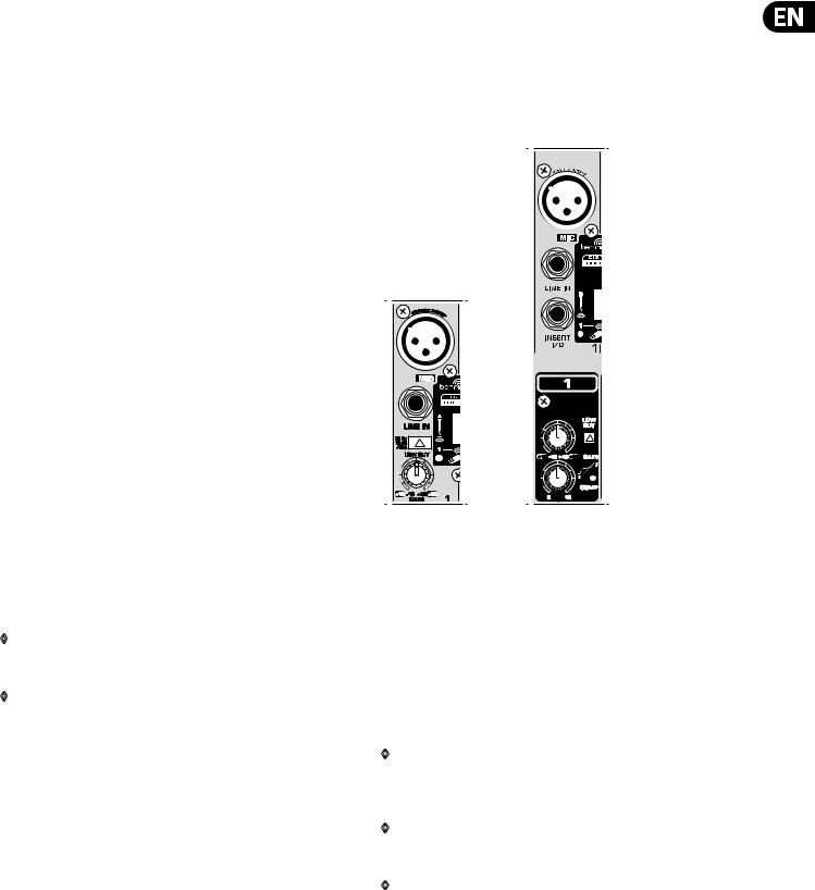
QX2222USB QX2442USB
Fig. 2.1: Connectors and controls of mic/line inputs
MIC
Each mono input channel offers a balanced microphone input via the XLR connector and also features switchable +48 V phantom power supply for condenser microphones. The XENYX preamps provide undistorted and noise-free gain as is typically known only from costly outboard preamps.
LINE IN
Each mono input also has a balanced line input on a ¼" jack. You can also connect unbalanced devices using mono cables to these inputs.
◊Please remember that you can use either the microphone input or the line input of a channel, but not both at the same time!
INSERT
◊Insert points enable the processing of a signal with dynamic processors or equalizers. They are sourced pre-fader, pre-EQ and pre-aux send. Detailed information on using insert points can be found in chapter 5.3.
◊Unlike the QX2442USB, the QX1622USB, QX1832USB and QX2222USB have their insert points located on the rear of the console.
6 XENYX QX2442USB/QX2222USB/QX1832USB/QX1622USB User Manual
WIRELESS INPUT
This connector accepts a USB receiver for use with BEHRINGER ULM wireless microphones. Note that only one source may be used per channel, either the wireless connection, XLR input, or the 1" input.
GAIN
Use the GAIN control to adjust the input gain. This control should always be turned fully counter-clockwise whenever you connect or disconnect a signal source to one of the inputs.
The scale has 2 different value ranges: the first value range (+10 to +60 dB) refers to the MIC input and shows the amplification for the signals fed in there.
The second value range (-10 to +40 dBu) refers to the line input and shows its sensitivity. The settings for equipment with standard line-level signals (-10 dBV or +4 dBu) look like this: While the GAIN control is turned all the way down, connect your equipment. Set the GAIN control to the external devices’ standard output level. If that unit has an output signal level display, it should show 0 dB during signal peaks. For +4 dBu, turn up GAIN slightly, for -10 dBV a bit more. Fine-tuning of a signal being fed in is done using the level meter.
To route the channel signal to the level meter, you have to press the SOLO switch and set the MODE switch in the main section to PFL (LEVEL SET).
Using the GAIN control, drive the signal to the 0-dB mark. This way you have a vast amount of drive headroom for use with very dynamic signals. The CLIP display should light up only rarely, preferably never. While fine-tuning,
the equalizer should be set to neutral.
LOW CUT
Additionally, the mono channels of the mixing consoles have a high-slope LOW CUT filter for eliminating unwanted, low-frequency signal components (75 Hz, 18 dB/octave).
COMPRESSOR
Each mono channel features a built-in compressor which lowers the dynamic range of the signal and increases its perceived loudness. The loud peaks are squashed down and the quiet sections are boosted.
Turn the COMP knob clockwise to add more compression effect. The adjacent LED with light when the effect is engaged.
2.1.2 Equalizer
All mono input channels have a 3-band equalizer with semi-parametric mid bands. All bands provide boost or cut of up to 15 dB. In the central position, the equalizer is off (flat).
The circuitry of the British EQ is based on the technology used in the best-known top-of-the-line consoles and providing a warm sound without any unwanted side effects. The result are extremely musical equalizers which, unlike simple equalizers, cause no side effects such as phase shifting or bandwidth limitation, even with extreme gain settings of ±15 dB.
All Models
Fig. 2.2: Equalizer of the input channels
The upper (HIGH) and the lower (LOW) bands are shelving filters that increase or decrease all frequencies above or below their cut-off frequency. The cut-off frequencies of the upper and lower bands are 12 kHz and 80 Hz respectively.
For the mid range, the console features a semi-parametric equalizer with a filter quality (Q) of 1 octave, tunable from 100 Hz to 8 kHz. Use the MID control to set the amount of boost or cut, and the FREQ control to determine the central frequency.
2.1.3 Monitor and effects busses (Aux Sends)
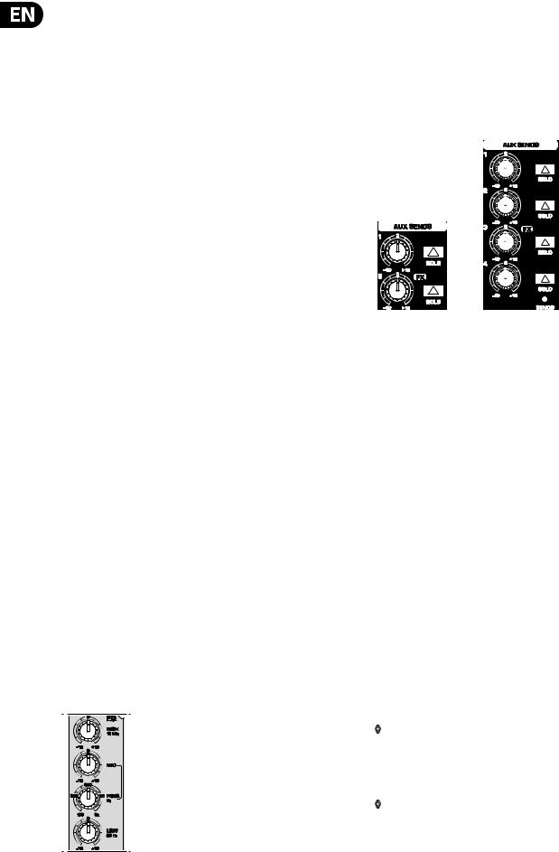
QX1622USB QX2442USB
Fig. 2.3: Aux Send control MON and FX in the channel strips
Monitor and effects busses (AUX sends) source their signals via a control from one or more channels and sum these signals to a so-called bus. This bus signal is sent to an aux send connector (for monitoring applications: MON OUT - QX1832USB) and then routed, for example, to an active monitor speaker or external effects device. In the latter case, the effects return can then be brought back into the console via the aux return connectors.
All monitor and effects busses are mono, are tapped into post EQ and offer amplification of up to +15 dB.
Pre-fader/post-fader
When using effects on a channel signal, it is usual to have the aux send post fader so that the balance between effect and dry signal stays constant even when
the channel fader is altered. If this were not the case, the effects signal of the channel would remain audible even when the channel fader is turned all the way down. For monitoring, the aux sends are generally pre-fader, i.e. they operate independently of the position of the channel fader.
PRE
When the PRE switch is pressed down, the associated aux send is taken pre-fader.
FX
The aux send marked FX offers a direct route to the built-in effects processor and is therefore post-fader and post-mute. Please refer to chapter 4 “Digital Effects Processor” for detailed information.
◊If you are using the built-in effects processor, make sure that STEREO AUX RETURN 3 has nothing plugged into it (QX2442USB and QX2222USB), otherwise the internal effects return will be muted. This is not relevant if you use the FX OUT jack to drive an external effects device.
◊QX1622USB and QX1832USB: On these consoles, the above note refers to the STEREO AUX RETURN 2 jacks as these models do not have a dedicated effect output.
7 XENYX QX2442USB/QX2222USB/QX1832USB/QX1622USB User Manual
2.1.4 Routing switch, PAN, SOLO and channel fader |
MAIN |
|
The MAIN switch routes the signal to the main mix bus. |
|
The channel fader determines the channel’s volume in the main mix (or submix). |
|
2.2 Stereo channels |
|
2.2.1 Channel inputs |
QX2442USB
Fig. 2.4: The panorama and routing controls and the channel fader
PAN
The PAN control determines the position of the channel signal within the stereo image. When working with subgroups, you can use the PAN control to assign the signal to just one output, which gives you additional flexibility in recording situations. For example, when routing to subgroups 3 and 4, panning hard left will route the signal to group output 3 only, and panning hard right will route to group output 4 only.
MUTE
The MUTE switch breaks the signal path pre-channel fader, hence muting that channel in the main mix. The aux sends which are set to post-fader are likewise muted for that channel, while the pre-fader monitor paths remain active irrespective of whether the channel is muted or not.
MUTE LED
The MUTE LED indicates a muted channel.
CLIP-LED
The CLIP-LED lights up when the input signal is driven too high. If this happens, back off the GAIN control and, if necessary, check the setting of the channel EQ.
SOLO
The SOLO switch is used to route the channel signal to the solo bus (Solo In Place) or to the PFL bus (Pre Fader Listen). This enables you to listen to a channel
signal without affecting the main output signal. The signal you hear is taken either before the pan control (PFL, mono) or after the pan and channel fader (Solo, stereo) (cf. chap. 2.3.10 “Level meters and monitoring”).
SUB (1-2 and 3-4)
The SUB switch routes the signal to the corresponding subgroups. The QX2442USB has 4 subgroups (1-2 and 3-4).
|
|
|
|
|
|
|
|
|
|
|
|
|
|
|
|
|
|
|
|
|
|
|
|
|
|
|
|
|
|
|
|
|
|
|
|
|
|
|
|
|
|
|
|
|
|
|
|
|
|
|
|
|
|
|
|
|
|
|
|
|
|
|
|
|
|
|
|
|
|
|
|
|
|
|
|
|
|
|
|
|
|
|
|
|
|
|
|
|
|
|
|
|
|
|
|
|
|
|
|
|
|
|
|
|
|
|
|
|
|
|
|
|
|
|
|
|
|
|
|
|
|
|
|
|
|
|
|
|
|
|
|
|
|
|
|
|
|
|
|
|
|
|
|
|
|
|
|
|
|
|
|
|
|
|
|
|
|
|
|
|
|
|
|
|
|
|
|
|
|
|
|
|
|
|
|
|
|
|
|
|
|
|
|
|
|
|
|
|
|
|
|
|
|
|
|
|
|
|
|
|
|
|
|
|
|
|
|
|
|
|
|
|
|
|
|
|
|
|
|
|
|
|
|
|
|
|
|
|
|
|
|
|
|
|
|
|
|
|
|
|
|
|
|
|
|
|
|
|
|
|
|
|
|
|
|
|
|
|
|
|
|
|
|
|
|
|
|
|
|
|
|
|
|
|
|
|
|
|
|
|
|
|
|
|
|
|
|
|
|
|
|
|
|
|
|
|
|
|
|
|
|
|
|
|
|
|
|
|
|
|
|
|
|
|
|
|
|
|
|
|
|
|
|
|
|
|
|
|
|
|
|
|
|
|
|
|
|
|
|
|
|
|
|
|
|
|
|
|
|
|
|
|
|
|
|
|
QX2222USB |
QX2442USB |
QX2442USB |
||||||||||||||||||
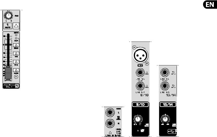
Fig. 2.5: The various stereo channel inputs
Each stereo channel has two balanced line level inputs on jacks for left and right channels. Channels 9/10 and 11/12 on the QX2442USB feature an additional XLR microphone jack with phantom power. If only the left jack (marked “L”)
is used, the channel operates in mono. The stereo channels are designed to handle typical line level signals, and, depending on model, have a level switch (+4 dBu or -10 dBV) and/or a line GAIN control. Both jack inputs will also accept unbalanced connectors.
LOW CUT and MIC GAIN
These two control elements operate on the XLR connectors of the QX2442USB, and are used to filter out frequencies below 75 Hz (LOW CUT) and to adjust microphone levels (MIC GAIN).
LINE GAIN
Use this control to adjust the line signal levels on channels 13-16 (QX2442USB only).
LEVEL
For level matching, the stereo inputs on the QX1622USB, QX1832USB and QX2222USB have a LEVEL switch to select between +4 dBu and -10 dBV.
At -10 dBV (homerecording level), the input is more sensitive than at +4 dBu (studio level).
8 XENYX QX2442USB/QX2222USB/QX1832USB/QX1622USB User Manual
2.2.2 Equalizer stereo channels
The stereo channels contain a stereo EQ section. The cut-off frequencies of the high and low bands are 12 kHz and 80 Hz respectively, while the center frequencies of the high-mid and low-mid bands are 3 kHz and 500 Hz
respectively. The HIGH and LOW controls have the same characteristics as the EQ in the mono channels. Both mid range bands are of the peak filter type. A stereo EQ is superior to two mono EQs on a stereo signal as two separate EQs will usually result in a discrepancy between left and right channels.
2.2.3 Aux sends stereo channels
In principle, the aux sends of the stereo channels function the same way as those of the mono channels. As the aux sends are mono, the send from a stereo channel is first summed to mono before it reaches the aux bus.
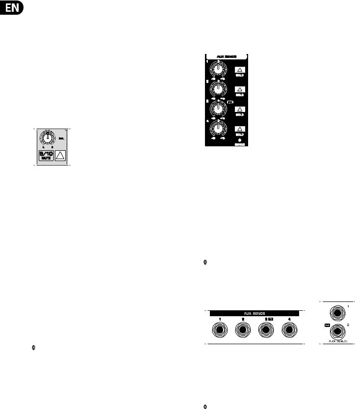
2.2.4 Routing switch, solo and channel fader
Fig. 2.6: Balance control and mute switch
BAL
The BAL(ANCE) control has a similar function to the PAN control in the mono channels.
The balance control determines the levels of the left and right input signals relative to each other before both signals are routed to the left/right main mix bus (or odd/even subgroup).
The remaining control elements in the stereo channels perform the same functions as their counterparts in the mono channels (MUTE switch, MUTE and CLIP LEDs, SOLO switch, SUB and MAIN switches and channel fader).
2.3 Interface panel and main section
Where it was useful to trace the signal flow from top to bottom in order to gain an understanding of the channel strips, we now look at the mixing console from left to right. The signals are, so to speak, collected from the same point on each of the channel strips and then routed to the main section all together.
2.3.1 MON control, aux sends 1, 2 and 3 (FX)
Turning up the AUX 1 control in a channel routes the signal to the aux send bus 1.
◊As the QX1832USB is equipped with an additional monitor path, its first aux control in the channel strips is named MON. The console also has a dedicated master fader (MON SEND) for this aux path.
AUX SEND 1, 2 and 4
The AUX SEND 1 control governs the master send level of the mix created by the individual channel AUX 1 sends.
Likewise, the AUX SEND 2 control is the master control for the aux 2 bus, and AUX SEND 4 controls the AUX 4 bus.
QX2442USB
Fig. 2.7: The AUX SEND controls of the main section
AUX SEND 3 (FX)
The FX control determines the signal level for effects processing, i.e. regulates the level to an external (or the internal) effects device.
QX1622USB and QX1832USB: On these consoles, this function is performed by the AUX SEND 2 control (FX).
SOLO
You can use the SOLO switch to separately monitor the aux sends via the CONTROL ROOM/PHONES outputs and check these with the level meters.
◊If you want to monitor the signal of just one AUX bus, none of the other SOLO SWITCHES should be pressed and the MODE switch should be in the SOLO position (not depressed).
2.3.2 Aux send jacks
|
|
|
|
|
|
QX2442USB |
QX1832USB |
|
Fig. 2.8: Aux send jacks
AUX SEND jacks
The AUX SEND jack should be used when hooking up a monitor power amp or active monitor speaker system. The relevant aux path should be set pre-fader.
◊On the QX2222USB, aux send 1 is hard wired as pre-fader and hence called MON. Model QX1832USB has a dedicated monitor output (MON OUT jack), cf. chapter 2.3.4.
As already mentioned, the aux sends in the channels— if set post-fader— can be used to connect to external effects devices.
Loading...