

Page 1
Dialog
+
®
Instructions for Use SW 9.1x
Dialysis Machine
Page 2

CE marking according to directive 93/42/EEC
Technical alterations reserved Manufacturer:
B. Braun Avitum AG
Rx only
34209 Melsungen, Germany
Tel +49 (56 61) 71-3716
Fax +49 (56 61) 75-3716
RTD.IM01 04/05
IFU 38910363US /Rev. 2.15.10 / May 2016
US Distributor:
B. Braun Medical Inc.
Avitum Division
Bethlehem, PA 18018-3524, USA
Made in Germany
Tel 1-800-621-0445
Fax (610) 691-1547
Page 3

Dialog+® Table of contents
1 Safe handling
2 Product description
3 Installation and commissioning
4 Therapy types
5 Preparing for hemodialysis
6 Initiating hemodialysis
7 Ending hemodialysis therapy
8 Disinfection
9 Single-needle procedure
1
2
3
4
5
6
7
8
9
10 Use of options
11 Configuration
12 Maintenance and cleaning
13 Alarms and remedial action
14 Accessories
15 Technical data
16 Appendix
10
11
12
13
14
15
16
Page 4

Table of contents Dialog+®
II IFU 38910363US / Rev. 2.15.10 / May 2016
Page 5

Dialog+® Table of contents
Table of contents
1 Safe handling ..........................................................................................1-3
1.1 Intended use and indications .............................................................. 1-3
1.2 Contraindications ................................................................................. 1-3
1.3 Side effects...........................................................................................1-3
1.4 About these Instructions for Use........................................................ 1-4
1.4.1 Applicability................................................................................................1-4
1.4.2 Target group...............................................................................................1-4
1.4.3 Warnings, notices and symbols in these Instructions for Use.....1-4
1.4.4 Abbreviations.............................................................................................1-6
1.5 Special hazards and precautions......................................................... 1-6
1.5.1 Special patient conditions......................................................................1-6
1.5.2 Electrical hazards......................................................................................1-7
1.5.3 Electromagnetic interaction..................................................................1-7
1.5.4 Maintenance and filter change.............................................................1-8
1.6 Information for the operator.............................................................. 1-8
1.6.1 Training by manufacturer prior to commissioning..........................1-8
1.6.2 User requirements.....................................................................................1-8
1.6.3 Conformity..................................................................................................1-8
1.6.4 Manufacturer’s warranty........................................................................1-9
1.6.5 Technical changes.....................................................................................1-9
1.7 Disposal.................................................................................................. 1-9
2 Product description ................................................................................ 2-3
2.1 Components ..........................................................................................2-4
2.1.1 Extracorporeal system .............................................................................2-4
2.1.2 Dialyzer........................................................................................................2-4
2.1.3 User interface.............................................................................................2-4
2.1.4 Control system...........................................................................................2-5
2.1.5 Balance chamber and UF-control.........................................................2-5
2.1.6 Water preparation ....................................................................................2-5
2.1.7 Concentrate preparation.........................................................................2-5
2.2 Basic models.......................................................................................... 2-6
2.2.1 Dialog+single-pump machine...............................................................2-9
2.3 Symbols on the dialysis machine......................................................2-10
2.4 Control elements and information on the monitor........................2-11
2.5 Overview of all icons..........................................................................2-13
2.6 Entering numerical values.................................................................2-20
2.7 Using the timer/stop watch...............................................................2-23
3 Installation and commissioning.............................................................3-3
IFU 38910363US / Rev. 2.15.10 / May 2016 III
Page 6

Table of contents Dialog+®
3.1 Scope of supply .................................................................................... 3-3
3.2 Storage.................................................................................................. 3-3
3.2.1 Storage in originally packed condition...............................................3-3
3.2.2 Interim storage of devices ready for operation................................3-3
3.2.3 Decommissioning......................................................................................3-3
3.3 Transportation...................................................................................... 3-4
3.3.1 Rolling..........................................................................................................3-4
3.3.2 Carrying.......................................................................................................3-5
3.4 Installation site..................................................................................... 3-6
3.4.1 Electrical connection ...............................................................................3-6
3.4.2 Protection against water damage........................................................3-6
3.4.3 Potentially explosive areas.....................................................................3-6
3.5 Water supply......................................................................................... 3-7
3.5.1 Quality of water and dialysate..............................................................3-7
3.5.2 Disposal of used fluids.............................................................................3-7
3.6 Initial commissioning........................................................................... 3-8
3.7 Setting date and time.......................................................................... 3-8
3.8 Switching on and off........................................................................... 3-9
4 Therapy types...........................................................................................4-3
4.1 Hemodialysis (HD)................................................................................ 4-3
4.2 Phases of pure ultrafiltration ............................................................. 4-3
4.3 Methods of treatment......................................................................... 4-4
4.3.1 Double-needle procedure .......................................................................4-4
4.3.2 Single-needle procedure.........................................................................4-4
4.4 Effectiveness of dialysis (Kt/V)........................................................... 4-5
5 Preparing for hemodialysis.....................................................................5-3
5.1 Initiating hemodialysis......................................................................... 5-4
5.2 Automatic test...................................................................................... 5-4
5.2.1 Operation during automatic test..........................................................5-5
5.2.2 Terminating the automatic test sequence.........................................5-6
5.2.3 Completion of automatic test sequence............................................5-6
5.3 Reducing the warning sounds during preparation............................ 5-6
5.4 Connecting the concentrate ............................................................... 5-8
5.5 Setting the rinsing parameters........................................................... 5-9
5.6 Inserting, rinsing and testing the tubing system............................5-11
5.6.1 Inserting standard A/V tubing............................................................5-12
5.6.2 Rinsing and testing standard A/V tubing........................................5-14
5.6.3 Level regulation during Preparation (if present)...........................5-14
5.6.4 Inserting Streamline® bloodline ........................................................5-16
5.6.5 Rinsing and testing the tubing system............................................5-17
5.7 Preparing the heparin pump .............................................................5-18
5.7.1 Inserting the heparin syringe..............................................................5-18
5.7.2 Venting the heparin line......................................................................5-19
IV IFU 38910363US / Rev. 2.15.10 / May 2016
Page 7

Dialog+® Table of contents
5.8 Setting the treatment parameters...................................................5-20
5.8.1 Setting the dialysate parameters ......................................................5-21
5.8.2 Monitoring the dialysate.....................................................................5-24
5.8.3 Sampling of dialysate for microbiology analysis ..........................5-25
5.8.4 Setting the ultrafiltration parameters .............................................5-27
5.8.5 Setting the pressure limits..................................................................5-29
5.8.6 Setting the heparin parameters.........................................................5-31
5.9 Rinsing the dialyzer............................................................................5-33
5.9.1 Rinsing the dialyzer using standard A/V tubing............................5-33
5.9.2 Rinsing the dialyzer using Streamline® bloodline........................5-34
5.10 Stand-by mode...................................................................................5-35
5.10.1 Activating the stand-by mode ...........................................................5-35
5.10.2 Switching off the stand-by mode.....................................................5-35
5.11 Power failure in preparation.............................................................5-36
5.12 Changing the bicarbonate cartridge during preparation...............5-36
6 Initiating hemodialysis ........................................................................... 6-3
6.1 Checking the patient data................................................................... 6-3
6.2 Connecting the patient and starting hemodialysis...........................6-4
6.2.1 Level regulation in therapy (if present)..............................................6-5
6.3 During hemodialysis............................................................................. 6-7
6.3.1 Monitoring the blood-side pressure limits........................................6-7
6.3.2 Treatment at minimum UF rate............................................................6-9
6.3.3 Heparin bolus..........................................................................................6-10
6.3.4 Arterial bolus (saline)............................................................................6-10
6.3.5 Graphic representation of treatment parameters (trend)..........6-12
6.3.6 Interrupting hemodialysis (bypass)...................................................6-15
6.3.7 Completion of treatment.....................................................................6-15
6.3.8 Terminating treatment .........................................................................6-15
6.3.9 Continuing treatment...........................................................................6-15
7 Ending hemodialysis therapy.................................................................7-3
7.1 Reinfusion .............................................................................................7-3
7.2 Emptying the cartridge after dialyzer drain...................................... 7-5
7.3 Emptying the dialyzer.......................................................................... 7-5
7.3.1 Removing dialyzer and blood tubing system ....................................7-5
7.4 Overview of the therapy carried out Touch icon.............................. 7-6
8 Disinfection ............................................................................................. 8-3
8.1 Procedure and disinfectants................................................................ 8-3
8.2 Preparing for disinfection ................................................................... 8-5
8.2.1 Positioning the disinfectant container...............................................8-5
8.2.2 Selecting the disinfection program.....................................................8-5
8.3 Automatic switch-off and restarting................................................. 8-7
8.3.1 Automatic switch-off after disinfection............................................8-7
8.3.2 Automatic switch-off and restarting..................................................8-7
IFU 38910363US / Rev. 2.15.10 / May 2016 V
Page 8

Table of contents Dialog+®
8.4 Chemical disinfection .......................................................................... 8-8
8.5 Short chemical disinfection ................................................................ 8-9
8.6 Thermal disinfection ..........................................................................8-10
8.7 Disinfection of incoming water from water supply........................8-11
8.7.1 Chemical disinfection with disinfecting solution
from central water supply...................................................................8-12
8.7.2 Automatic chemical disinfection with disinfectant
from central water supply...................................................................8-13
8.7.3 Thermal disinfection with hot permeate from
central water supply.............................................................................8-15
8.7.4 Rinsing the permeate inlet..................................................................8-16
8.8 Checking for disinfectant residues...................................................8-17
8.9 Decalcification....................................................................................8-18
8.9.1 Automatic descaling .............................................................................8-18
8.10 Terminating disinfection ...................................................................8-20
9 Single-needle procedure ........................................................................9-3
9.1 Single-needle valve (SN-valve) .......................................................... 9-3
9.1.1 Preparing the therapy..............................................................................9-3
9.1.2 Level regulation in SN-valve mode (if present)................................9-5
9.1.3 Running the therapy................................................................................9-7
9.1.4 Ending the therapy...................................................................................9-8
10 Use of accessories and options........................................................... 10-3
10.1 ABPM blood pressure monitoring.....................................................10-3
10.1.1 Cuff............................................................................................................10-3
10.1.2 Settings.....................................................................................................10-5
10.1.3 Starting/stopping measurement........................................................10-8
10.1.4 Showing and graphically displaying measured values................10-9
10.2 Bicarbonate cartridge holder..........................................................10-10
10.2.1 Inserting the cartridge........................................................................10-10
10.2.2 Changing the cartridge during dialysis..........................................10-11
10.2.3 Emptying the cartridge after treatment........................................10-14
10.3 Central concentrate supply.............................................................10-15
10.4 AdimeaTMOption UV – Kt/V............................................................10-16
10.4.1 Setting the parameters.......................................................................10-17
10.4.2 Graphic representation during therapy .........................................10-18
10.4.3 Target warning......................................................................................10-20
10.4.4 Extended functionality when using
the patient therapy card....................................................................10-21
10.4.5 Kt/V table ...............................................................................................10-23
10.5 Dialysis fluid filter............................................................................10-24
10.5.1 Use and mode of operation...............................................................10-24
10.5.2 Changing dialysis fluid filter.............................................................10-25
10.5.3 Resetting the data...............................................................................10-28
10.5.4 Disinfection............................................................................................10-29
10.6 Emergency power supply/battery ...................................................10-30
10.6.1 Charging indicator...............................................................................10-31
VI IFU 38910363US / Rev. 2.15.10 / May 2016
Page 9

Dialog+® Table of contents
10.6.2 Automatic battery test.......................................................................10-31
10.6.3 Ending battery operation...................................................................10-32
10.7 Communication interfaces ..............................................................10-32
10.7.1 Dialog+computer interface (DCI)....................................................10-32
10.8 Rinse bucket......................................................................................10-32
10.8.1 Care of the rinse bucket.....................................................................10-32
11 Configuration........................................................................................11-3
11.1 Automatic switch-off........................................................................11-3
11.2 Weekly disinfection program............................................................11-5
11.3 Configuring the weekly disinfection program.................................11-6
11.4 Configuring profiles...........................................................................11-9
11.4.1 Basic principles.......................................................................................11-9
11.4.2 Setting profile parameters ..................................................................11-9
11.5 UF profiles.........................................................................................11-11
11.5.1 Selecting UF profiles...........................................................................11-11
11.5.2 UF profile table.....................................................................................11-13
11.6 Patient therapy chip card................................................................11-18
11.6.1 Erasing data from patient therapy card........................................11-18
11.6.2 Entering the patient name................................................................11-19
11.6.3 Reading patient data..........................................................................11-20
11.6.4 Storing patient data (parameter settings)....................................11-20
11.7 Theoretical Kt/V calculation ...........................................................11-21
11.8 Adjusting monitor brightness..........................................................11-26
11.9 Selecting language of screen text..................................................11-27
11.10 Editing trend group parameters .....................................................11-28
12 Maintenance and cleaning ..................................................................12-3
12.1 External cleaning................................................................................12-3
12.2 Preventive maintenance and technical safety inspection..............12-4
12.2.1 Regular preventive maintenance.......................................................12-4
12.2.2 Technical safety inspection.................................................................12-5
12.2.3 Accessories, disposable items and expendable parts...................12-5
12.3 Technical service and warranty ........................................................12-5
12.3.1 Warranty...................................................................................................12-5
12.4 Disposal of old dialysis machines......................................................12-5
13 Alarms and remedial action.................................................................13-3
13.1 Displaying and resetting alarms........................................................13-3
13.2 Alarms and consequences..................................................................13-5
13.3 Remedying SAD alarms when using
standard A/V tubing systems ..........................................................13-39
13.4 Manual blood return........................................................................13-41
IFU 38910363US / Rev. 2.15.10 / May 2016 VII
Page 10

Table of contents Dialog+®
13.5 Muting acoustic signals...................................................................13-43
13.5.1 Muting acoustic signals for alarms................................................13-43
13.5.2 Muting acoustic signals for messages...........................................13-43
14 Accessories and options....................................................................... 14-3
14.1 Accessories and options.....................................................................14-3
14.2 Additional accessories........................................................................14-4
14.3 Configurations....................................................................................14-4
15 Technical data ...................................................................................... 15-3
15.1 General technical data ......................................................................15-3
15.2 Ambient conditions............................................................................15-4
15.3 Recommended safe distances ...........................................................15-5
15.4 Dialysate system.................................................................................15-6
15.5 Extracorporeal circulation.................................................................15-9
15.6 Materials coming into contact with water, dialysate,
dialysis concentrates and/or disinfectants ....................................15-11
15.7 ABPM blood pressure monitoring...................................................15-12
15.8 Technical data of Crit-Line® interface..........................................15-13
16 Appendix ............................................................................................... 16-3
16.1 Dialysate flow chart...........................................................................16-3
16.1.1 Key to dialysis flow chart....................................................................16-3
16.1.2 Flow chart Dialog+.................................................................................16-5
16.2 Service protocols................................................................................16-6
VIII IFU 38910363US / Rev. 2.15.10 / May 2016
Page 11

Dialog+® Safe handling
Table of contents
1 Safe handling....................................................................................... 1-3
1.1 Intended use and indications .............................................................. 1-3
1.2 Contraindications ................................................................................. 1-3
1.3 Side effects...........................................................................................1-3
1.4 About these Instructions for Use........................................................ 1-4
1.4.1 Applicability................................................................................................1-4
1.4.2 Target group...............................................................................................1-4
1.4.3 Warnings, notices and symbols in these Instructions for Use.....1-4
1.4.4 Abbreviations.............................................................................................1-6
1.5 Special hazards and precautions......................................................... 1-6
1.5.1 Special patient conditions......................................................................1-6
1.5.2 Electrical hazards......................................................................................1-7
1.5.3 Electromagnetic interaction..................................................................1-7
1.5.4 Maintenance and filter change.............................................................1-8
1.6 Information for the operator.............................................................. 1-8
1.6.1 Training by manufacturer prior to commissioning..........................1-8
1.6.2 User requirements.....................................................................................1-8
1.6.3 Conformity..................................................................................................1-8
1.6.4 Manufacturer’s warranty........................................................................1-9
1.6.5 Technical changes.....................................................................................1-9
1
1.7 Disposal.................................................................................................. 1-9
IFU 38910363US / Rev. 2.15.10 / May 2016 1-1
Page 12

1
Safe handling Dialog+®
1-2 IFU 38910363US / Rev. 2.15.10 / May 2016
Page 13

Dialog+® Safe handling
1 Safe handling
1.1 Intended use and indications
This dialysis machine can be used for implementing and monitoring hemodialysis
treatments for patients with acute or chronic kidney failure. The system can be used in
hospital, health center and outpatient dialysis center settings when prescribed by a
physician.
The following types of renal replacement therapy can be carried out with the system:
• Hemodialysis (HD) with or without phases of pure ultrafiltration
high flux hemodialysis
low flux hemodialysis
1.2 Contraindications
There are no known contraindications for chronic hemodialysis.
The doctor in charge of the treatment is responsible for choosing the suitable therapy,
based on medical and analytical findings and the general health and condition of the
patient.
1
1.3 Side effects
Hypotension, nausea, vomiting and cramps are possible side effects.
Hypersensitivity reactions caused by using the necessary tubing and filter materials
have been observed in only a few cases. For more information on this matter, please
refer to the product information provided with the disposables.
IFU 38910363US / Rev. 2.15.10 / May 2016 1-3
Page 14

Safe handling Dialog+®
1
1.4 About these Instructions for Use
These Instructions for Use form an integral part of the dialysis machine. They describe
the appropriate and safe use of the dialysis machine at all stages of operation.
The dialysis machine must always be used in accordance with the Instructions for
Use.
Always keep the Instructions for Use at the dialysis machine for later use.
Pass on Instructions for Use to any future user of the dialysis machine.
1.4.1 Applicability
Art. no.
These Instructions for Use apply to Dialog+dialysis machines with the following article
numbers (art. no.):
• 710200K
• 710200L (with bicarbonate cartridge holder)
• 710220U (with Adimea, DF filter, WAN-BSL)
• 710200S (with bicarbonate cartridge holder, Adimea, DF filter, WAN-BSL)
Software version
These Instructions for Use apply to software version 9.1x (x = any)
1.4.2 Target group
The target group for these Instructions for Use is the dialysis medical staff.
The dialysis machine may only be used by persons instructed in its appropriate
operation. Furthermore, all clinical parameters have to be ordered and controlled by a
physician.
1.4.3 Warnings, notices and symbols in these Instructions for Use
Warnings in these Instructions for Use point out particular hazards for users, patients,
third parties and the dialysis machine. They also suggest measures that can be taken
to avoid the respective hazard.
1-4 IFU 38910363US / Rev. 2.15.10 / May 2016
Page 15
Dialog+® Safe handling
DANGER
WARNING
CAUTION
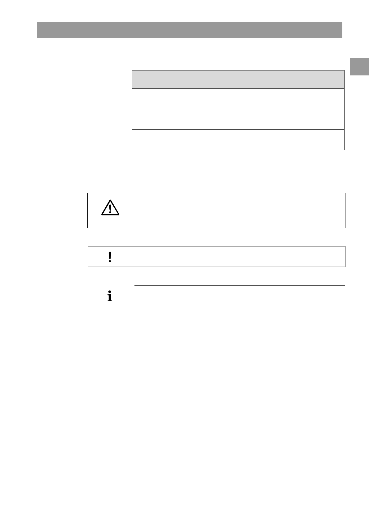
There are three levels of warning notices:
Warning term Meaning
Imminent danger that can lead to death or serious injury if not
avoided
Potentially imminent danger that can lead to death or serious
injury if not avoided
Potentially imminent danger that can lead to minor injuries or
damage to equipment if not avoided
The warning notices are highlighted in the following manner (see below example for a
CAUTION warning):
Here the type and source of the danger are listed, and possible consequences if
the preventive measures are not followed!
CAUTION
This is the list of measures to prevent the hazard.
1
This is the list of important information, directly or indirectly relating to safety and
the prevention of damage.
This is additional useful information concerning safe procedures, background
information and recommendations.
This symbol marks the instructions for action.
IFU 38910363US / Rev. 2.15.10 / May 2016 1-5
Page 16
Safe handling Dialog+®
1
1.4.4 Abbreviations
ABPM Automatic blood pressure monitoring
BPA Arterial blood pump
BPV Venous blood pump
HD Hemodialysis
HP Heparin pump
PA Arterial pressure
PBE Blood-side entry pressure at dialysis machine
PBS Blood pump control pressure for single-needle procedure
PV Venous pressure
RDV Venousred detector
SAD Safety air detector
SAKA Arterial tube clamp
SAKV Venous tube clamp
SN Single-needle
TMP Trans membrane pressure
TSM Technical support and maintenance mode
UF Ultrafiltration
ZKV Central concentrate supply
WARNING
1.5 Special hazards and precautions
1.5.1 Special patient conditions
The patient’s physician must be notified of any special patient conditions, such as
unstable circulation or hypokalemia, prior to therapy.
Fluid Balance deviations can exceed a level that can be tolerated by low weight
patients, even if deviations are within the specified Dialog+accuracy value, and
in particular if the weight of the patients is equal or lower than 30 kg.
The treatment of these patients shall be performed under the full supervision
of the physician.
In these cases, the use of an additional device to measure the weight loss is
recommended.
The appropriate dialyzer and blood line must be selected according to the
patient’s size, weight and treatment type.
1-6 IFU 38910363US / Rev. 2.15.10 / May 2016
Page 17
Dialog+® Safe handling
WARNING
1.5.2 Electrical hazards
The dialysis machine contains life-threatening electrical voltages.
Risk of electric shock and fire.
Always insert mains plug completely into the mains socket.
Always pull/push on the plug and not on the mains cord to connect or
disconnect the mains plug.
Avoid damage of the mains cord. (For example by running over it with the
machine.)
It must not be used or connected to mains voltage if the housing or the power cord is
damaged in any way. A damaged dialysis machine must be submitted for repairs or
disposal.
Interaction with other devices
When using the dialysis machine in combination with other therapeutic devices, a
potential equalization device must be connected, since the leakage currents from all
connected devices are summarized and the electrostatic discharge from the
environment to Dialog+may occur.
Do not connect customary consumer devices to the same power socket as the dialysis
machine or connect them in parallel.
1
CAUTION
Use with central-venous catheter
For patients with a central venous catheter, a higher degree of protection against
electric shock is required. As electric currents can run through supply lines, via the
dialyzer, the catheter, the patient and every conducting object in the vicinity of the
patient, electrical potential equalization must be provided. As soon as earth potential
equalization is connected to the machine the patient leakage current has to be below
10 A, which complies with the limit value for patient leakage current of type CF. A
potential equalization cable is available, which can be connected to the bolt at the
rear side of the machine. The ambient conditions of the premises must be in
accordance to the local requirements (see also chapter 1.6.4).
1.5.3 Electromagnetic interaction
The dialysis machine has been developed and tested in accordance with the valid
standards for interference suppression and EMC. It cannot, however, be guaranteed
that no electromagnetic interaction with other devices will occur (examples: mobile
phones, computer tomograph [CT]).
Risk of electrostatic discharge from other devices.
It is recommended that mobile phones and other devices emitting strong
electromagnetic radiation only be used at a minimum distance, according to
IEC 60601-1-2 (see also chapter 15.3).
IFU 38910363US / Rev. 2.15.10 / May 2016 1-7
Page 18
Safe handling Dialog+®
1
CAUTION
If other therapeutic or diagnostic medical devices are placed on, near by, or
nonmedical devices are used near Dialog+, they may have an influence on
electromagnetic interactions. The user must observe the proper operation of Dialog
and all other machines when these combinations exist.
1.5.4 Maintenance and filter change
In order to protect patients against cross-contamination, the transducer protectors of
standard tubing systems are equipped with hydrophobic 0.2 m filters.
Risk to patient due to infection as a result of contamination of the transducer
protector on the tubing system!
Replace the machine-side transducer protector if it has been contaminated
with blood.
Instruct technical service to replace transducer protector, tubing and pressure
port.
Execute disinfection after replacement.
Only use the machine again when the filter has been changed.
1.6 Information for the operator
+
CAUTION
Rx only!
1.6.1 Training by manufacturer prior to commissioning
The operator may use this device only after the manufacturer has trained the
responsible staff based on these Instructions for Use.
1.6.2 User requirements
The dialysis machine may be used only by persons instructed in its appropriate
operation.
The operator must ensure that the Instructions for Use are read and understood by all
operators of the dialysis machine.
Prior to using the dialysis machine, check for safe functioning and correct
conditioning of the dialysis machine.
1.6.3 Conformity
This dialysis machine complies with the requirements of the generally applicable
standards in their respective valid version:
• ANSI/AAMI/IEC 60601-1
• IEC 60601-2-16
Additional equipment connected to the analog or digital interfaces of the dialysis
machine must demonstrably meet the relevant IEC specifications (e.g. IEC 60950 for
data processing devices and IEC 60601-1 for electromedical devices). Also, all
1-8 IFU 38910363US / Rev. 2.15.10 / May 2016
Page 19

Dialog+® Safe handling
configurations must conform with the valid version of the System Standard
IEC 60601-1-1.
Persons connecting additional devices to signal input or output components are
performing a system configuration and are thus responsible for ensuring that the
system is compliant with a valid version of the System Standard IEC 60601-1-1. In
case of questions, please contact your local specialist dealer or technical service.
In each country the distribution of the machine is carried out provided that the device
is registered and classified according to the local regulations.
USA
In the USA, the dialysis machine is a class II device complying with the fundamental
requirements of 21 CFR (Code of Federal Regulations) §876.5860.
1.6.4 Manufacturer’s warranty
The manufacturer, assembler, installer or implementer may only be responsible for the
effects on the safety, reliability and performance of the device, if:
• the assembly, expansion, readjustments, changes or repairs were carried out by a
person authorized by the manufacturer.
• the electrical installation of the affected room complies with the valid national
requirements on the equipment of medical treatment rooms (i. e. IEC stipulations).
The device may be operated only if the manufacturer or an authorized person, acting
on behalf of the manufacturer:
• has carried out a functional check on site (initial commissioning),
• if the persons appointed by the operator to use the device have been trained in the
correct handling, use and operation of the medical product with the aid of the
Instructions for Use, enclosed information and maintenance information and
• if the quality of the water used with the device corresponds to the relevant
standards.
1
1.6.5 Technical changes
We reserve the right to change our products in line with further technical
developments.
1.7 Disposal
Dialysis machines may be returned to the manufacturer for disposal in accordance
with the applicable disposal guidelines.
The Dialysis machine has to be disinfected according to regulations before disposal.
IFU 38910363US / Rev. 2.15.10 / May 2016 1-9
Page 20

1
Safe handling Dialog+®
1-10 IFU 38910363US / Rev. 2.15.10 / May 2016
Page 21

Dialog+® Product description
Table of contents
2 Product description ............................................................................. 2-3
2.1 Components ..........................................................................................2-4
2.1.1 Extracorporeal system .............................................................................2-4
2.1.2 Dialyzer........................................................................................................2-4
2.1.3 User interface.............................................................................................2-4
2.1.4 Control system...........................................................................................2-5
2.1.5 Balance chamber and UF-control.........................................................2-5
2.1.6 Water preparation ....................................................................................2-5
2.1.7 Concentrate preparation.........................................................................2-5
2.2 Basic models.......................................................................................... 2-6
2.2.1 Dialog+single-pump machine...............................................................2-9
2.3 Symbols on the dialysis machine......................................................2-10
2.4 Control elements and information on the monitor........................2-11
2
2.5 Overview of all icons..........................................................................2-13
2.6 Entering numerical values.................................................................2-20
2.7 Using the timer/stop watch...............................................................2-23
IFU 38910363US / Rev. 2.15.10 / May 2016 2-1
Page 22

2
Product description Dialog+®
2-2 IFU 38910363US / Rev. 2.15.10 / May 2016
Page 23
Dialog+® Product description
Model #710200L, single
-
pump
Bicarbonate cartridge holder
2 Product description
The Dialog+is a Hemodialysis Delivery System Machine available in four models
Model # 710200K: Dialog+single-pump
Model # 710200L: Dialog+single-pump, with bicarbonate cartridge holder
Model # 710200U: Dialog+single-pump, with Adimea, DF filter, WAN-BSL
Model # 710200S: Dialog+single-pump, with bicarbonate cartridge holder, Adimea,
DF filter, WAN-BSL
The Dialog+machine is suitable for hospital hemodialysis and also for dialysis centers.
It can use and store different profiles for many parameters such as: UF, sodium,
bicarbonate, heparin, dialysate flow, and temperature.
Treatment can be performed with bicarbonate or acetate concentrate supplied from a
canister or from central supply. A bicarbonate cartridge can be used as well.
configuration with bicarbonate
cartridge holder
2
Fig. 2-1 Dialog+system models
IFU 38910363US / Rev. 2.15.10 / May 2016 2-3
Page 24

2
“Disposables“
“Dialog
+
machine
“
Product description Dialog+®
2.1 Components
The Dialog+system consists of the following components:
Extracorporeal circulation system
Dialyzer
User interface
Control and safety monitoring systems, e.g. auto clamps, alarms, etc.
Balance chamber and UF control
Water preparation
Concentrate preparation
2.1.1 Extracorporeal system
The extracorporeal system consists of the machine’s peristaltic pumps, which are used
to transport the blood to the dialyzer and from the dialyzer back to the patient.
Blood is pumped through a disposable extracorporeal system mainly composed of
tubing, connectors, drip chambers and the dialyzer.
Peristaltic pumps withdraw blood from the patient’s vascular access into the dialyzer.
A syringe pump pumps heparin into the bloodlines in a quantity and time set by the
user to avoid the coagulation of the blood in the disposable circuit and the dialyzer
filter.
2.1.2 Dialyzer
The capillary dialyzer houses semipermeable hollow fibers encased in a plastic canister.
The dialyzer is used to correct the concentration of water-soluble substances in the
patients blood before delivering it back to the patient. The blood is separated from the
dialyzing fluid by a semi-permeable membrane that permits bidirectional diffusive
transport and ultrafiltration. The process also allows diffusion of substances from the
dialyzing fluid into the blood.
2.1.3 User interface
The user interface is a display panel that provides communication between the
machine and the user. On the display it is possible to visualize all the dialysis
parameters and relevant information about the procedure and alarm conditions.
By touching the icons on the screen, the user can input all the parameters for the
treatment such as: dialysis time, UF volume and heparin pump flow. Several profiles
for the procedure can be selected and set via the interface.
The five buttons at the bottom of the screen (see Fig. 2-6) have fixed functions i.e.,
control the arterial pump, to enter and confirm the entry input and to reset the alarms.
2-4 IFU 38910363US / Rev. 2.15.10 / May 2016
Page 25

Dialog+® Product description
2.1.4 Control system
The control system is divided into two parts:
The top level control system connects the interface with the user and transmits data
to and from other modules. The low level control system controls and monitors the
machine and its functions and also communicates with the top level control system.
Both systems operate independently of each other.
2.1.5 Balance chamber and UF-control
The balance chamber system is a closed system and consists of two chambers, each
with a flexible membrane, allowing it to fill the chambers from one side while an
identical volume is emptied to the other side. Therefore the outlet fluid volume is
equal to the input fluid volume.
Each membrane has a magnetic sensor which reads the membrane position and
controls the opening and the closing of each sub compartment.
The control of the dialysate volume is also carried out by the balance chamber. The
difference between used dialysate and fresh dialysate is the ultrafiltration volume,
which is removed from the blood side of the dialyzer. Ultrafiltrate removal is carried
out by the UF pump.
2
2.1.6 Water preparation
Purified water coming from the reverse osmosis system has to be degassed and
tempered to a predetermined temperature, which is set by the user (usually
37°C/99 °F), before the concentrate is prepared. A degassing chamber and a heater are
integral to the system.
2.1.7 Concentrate preparation
In bicarbonate dialysis, which is the most common procedure, concentrate preparation
consists of mixing the heated and degassed water with bicarbonate concentrate and
acid concentrate. The accuracy of dialysate concentration is controlled by conductivity
sensors. If the concentration is incorrect, the dialyzer will be bypassed.
IFU 38910363US / Rev. 2.15.10 / May 2016 2-5
Page 26
Product description Dialog+®
Venous pressure sensor
Venous tube clamp
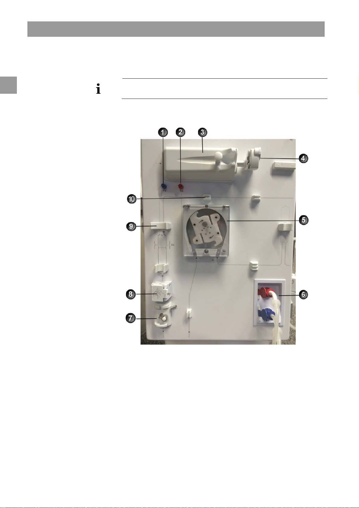
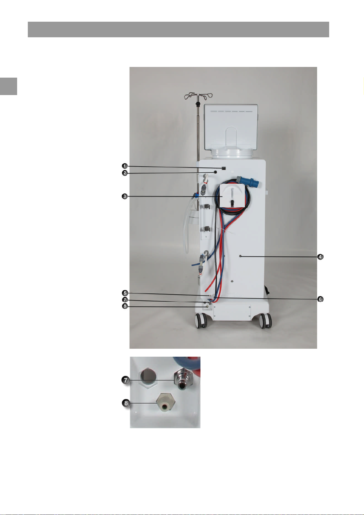
2.2 Basic models
2
Legend
1
connection (blue)
Arterial pressure sensor
2
connection (red)
Heparin pump
3
Syringe stop
4
Blood pump (one or two blood
5
pumps depending on basic
model)
Rinsing chambers for
6
concentrate rods
7
Safety air detector (SAD) and red
8
sensor
Fixture for the chamber of the
9
blood tubing system
Fixture for blood tubing system
10
The basic model Dialog+single-pump machine is shown in the figure below. The
legend highlights the components installed in all basic models.
Front view
2-6 IFU 38910363US / Rev. 2.15.10 / May 2016
Fig. 2-2 Basic model single-pump, front view
Page 27
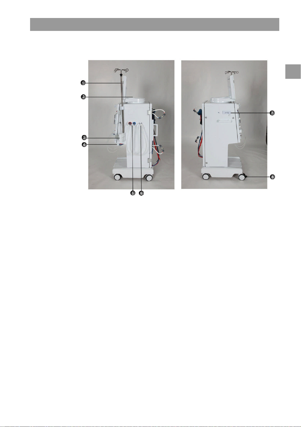
Dialog+® Product description
Legend
Infusion pole (in
1
some models, pole
may not be
adjustable)
Multi Functional
2
Tray
Bicarbonate
3
cartridge holder
(optional)
Connection for
4
central
concentrate supply
(optional)
Connection for
5
disinfectant
Connections for
6
dialyzer tubing and
rinsing bridge
Card reader
7
Wheel lock
8
2
Fig. 2-3 Basic model, side views
IFU 38910363US / Rev. 2.15.10 / May 2016 2-7
Page 28
2
Product description Dialog+®
Legend
Mains switch
1
WAN-BSL
2
Crank for manual blood return
3
Fixture for disinfectant
4
container
Ground connection
5
Power cord
6
Water inlet
7
Dialysate outlet
8
Water inlet
7
Dialysate outlet
8
Fig. 2-4 Basic model, rear view
2-8 IFU 38910363US / Rev. 2.15.10 / May 2016
Page 29

Dialog+® Product description
2.2.1 Dialog+single-pump machine
The Dialog+single-pump dialysis machine is suitable for hospitals, health centers and
outpatient dialysis centers. It offers the following features as standard:
• Color screen and on-screen operation (color touch screen)
• Acetate/bicarbonate operation
• Volumetric ultrafiltration
• Heparin syringe pump
• Heat exchanger
• Fixed or freely selectable profile controls for dialysate composition, temperature
and flow rate, for heparin supply and for ultrafiltration
The following features are available as additional accessories/options:
• Automatic blood pressure monitoring (ABPM)
• Bicarbonate cartridge holder
• Level regulation
• Central concentrate supply (ZKV)
• Dialysis fluid filter
• Dialysis fluid filter holder
• Emergency power supply
• Data interface
– Dialog+computer interface (DCI)
– WAN BSL (Bed Side Link): Card reader and interface to data management system
– Card reader
• AdimeaTMOption UV–Kt/V
2
Therapy types
The Dialog+dialysis machine with a single blood pump can be used for the following
therapy procedures:
• Hemodialysis (HD) with or without phases of pure ultrafiltration
• High-flux hemodialysis
• Low-flux hemodialysis
Methods of treatment
The Dialog+dialysis machine with a single blood pump can be used for the following
therapy methods:
• Double-needle procedure
• Single-needle procedure
IFU 38910363US / Rev. 2.15.10 / May 2016 2-9
Page 30
2
Product description Dialog+®
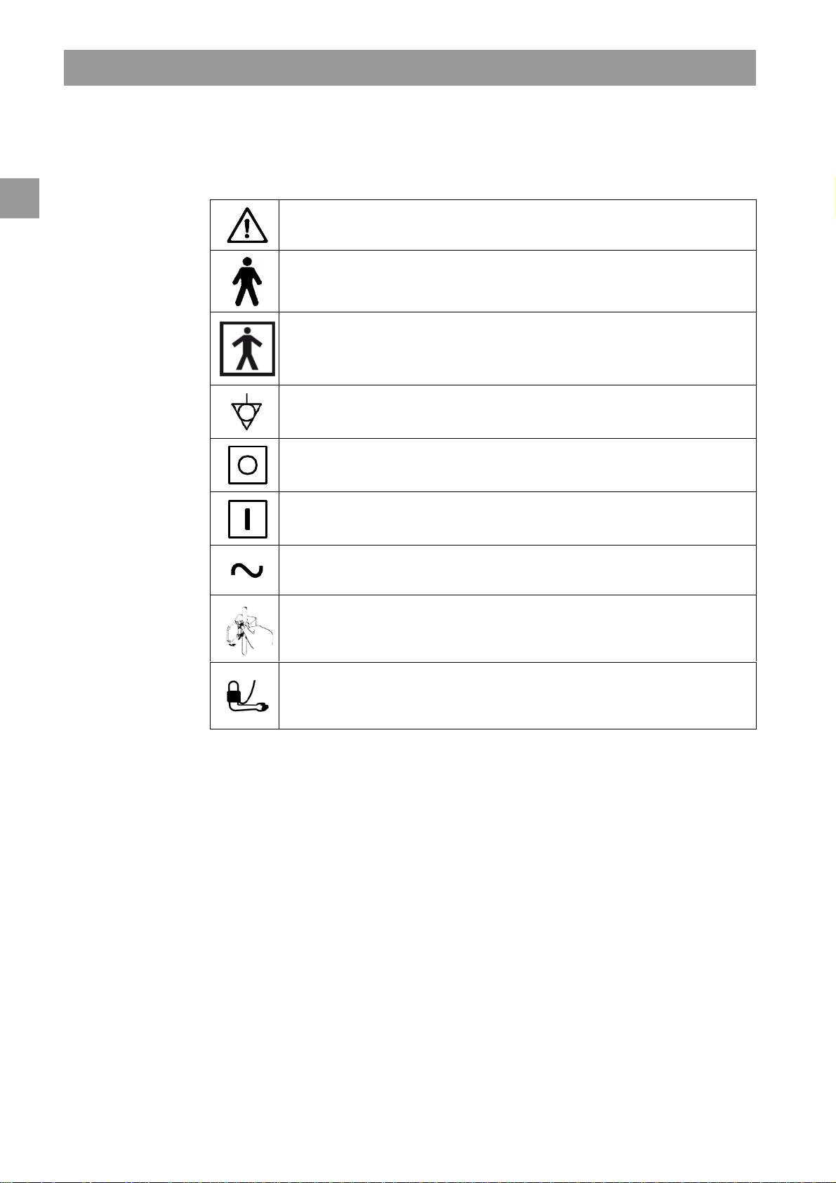
2.3 Symbols on the dialysis machine
Observe Instructions for Use
Observe Safety information
Type B applied part
Classification acc. to IEC 60601-1
Type BF applied part
Classification acc. to IEC 60601-1
Electrical ground
Dialysis machine OFF
Dialysis machine ON
Alternating current
Schematic illustration on safety air detector (SAD), showing the correct way of
installing the tube
Connection for optional automatic blood pressure monitoring (ABPM)
2-10 IFU 38910363US / Rev. 2.15.10 / May 2016
Page 31
Dialog+® Product description
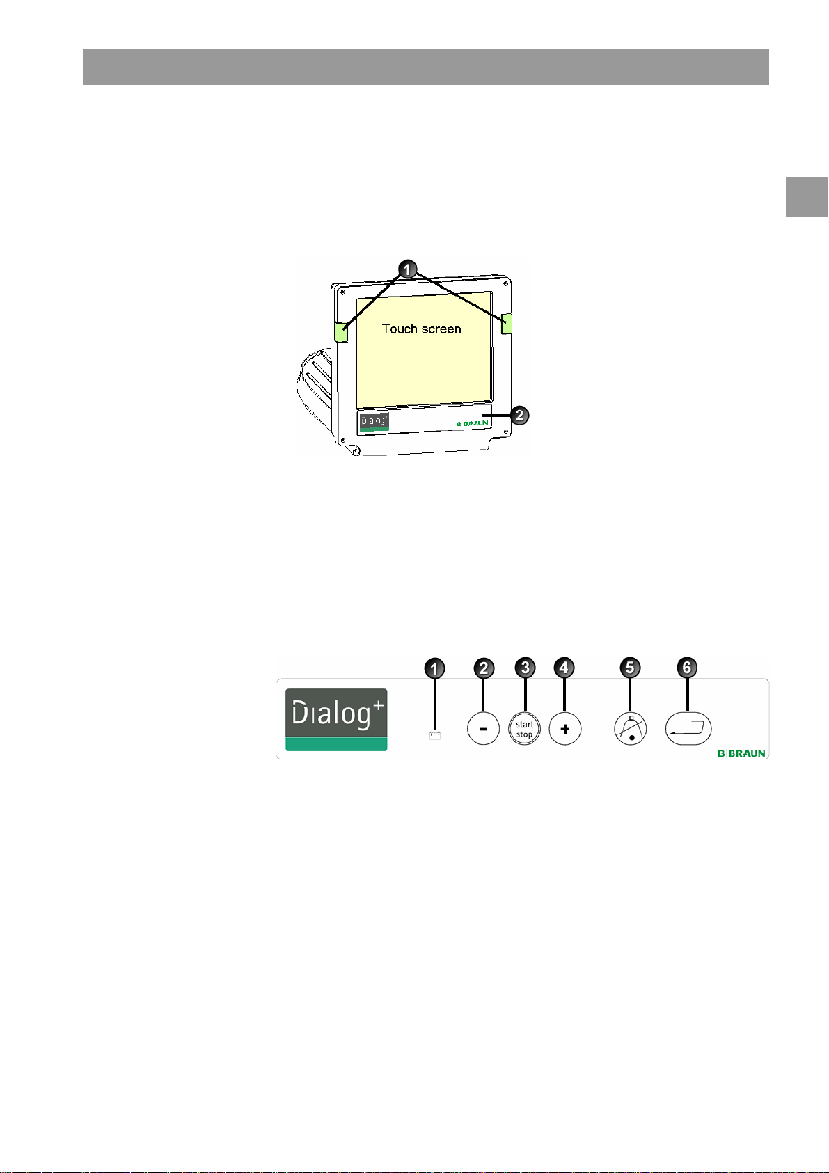
2.4 Control elements and information on the monitor
Legend
Signal lamps:
1
Green = operation
Yellow = warning/note
Red = alarm
Buttons on the monitor
2
Signal lamps
Signal lamps on the left and right of the monitor light up in three different colors to
indicate the conditions "Operation", "Warning" and "Alarm".
Fig. 2-5 Monitor
Buttons on the monitor
2
Even with the screen switched off (e.g. during cleaning), the basic functions of the
dialysis machine can be controlled via the buttons on the monitor.
The “+” and “-“ buttons (buttons 2 and 4) automatically count up or down by holding
the button down.
Fig. 2-6 Buttons on the monitor
Legend
Battery symbol (display only): Battery charging
1
Reduce blood pump speed
2
Switch on/switch off blood pump
3
Increase blood pump speed
4
Confirm alarm (when button is illuminated); switches off
5
the alarm buzzer
Enter button: Confirm entered data and reset information
6
(if button is illuminated)
IFU 38910363US / Rev. 2.15.10 / May 2016 2-11
Page 32

2
Product description Dialog+®
Touch Screen
Most functions of the dialysis machine are controlled via the touch screen.
The screen displays different contents (windows) depending on the activated program
section. Different parts (fields and icons) of the screen react to touch. By touching one
of these areas, another window is called up or a stored action is triggered.
Some windows show a lateral scroll bar. They could be scrolled by moving a finger on
the scroll bar.
Legend
Screen
1
Fields
2
Icons
3
Call up help function for
4
explaining the icons
Fig. 2-7 Screen display
2-12 IFU 38910363US / Rev. 2.15.10 / May 2016
Page 33

Dialog+® Product description
2.5 Overview of all icons
Icons are control buttons on the touch screen used for operating the dialysis machine.
Depending on the displayed window, different icons are available, which all represent
a specific action. By touching an icon, the respective action is carried out. A list of all
icons is provided below.
Leave window and accept data
Leave window without accepting data
Help function for explaining the icons
History of current disinfection
2
Service screen
Switch off all icon functions for 10 sec to allow cleaning of monitor
Set brightness of monitor
Leave current window
Overview/ Table of contents
Related parameter window
IFU 38910363US / Rev. 2.15.10 / May 2016 2-13
Page 34

Product description Dialog+®
Set treatment parameters
2
Return to program selection
Erase chip card
Read patient data from chip card
Save patient data to chip card
Select further setting options
Reduce value
Increase value
Red symbol: error symbol during reading of patient data from chip card
to be consistent
In profile window (except for UF profile): open numerical keypad for
resetting the profile to a setting
Key pad for entering numerical values
Give heparin bolus
Give arterial bolus (e.g. saline)
2-14 IFU 38910363US / Rev. 2.15.10 / May 2016
Page 35

Dialog+® Product description
Window for setting arterial bolus
Dialyzer rinsing program with simultaneous ultrafiltration
Empty dialyzer – dialysate is siphoned out of the dialyzer
Set heparinization data
Reset filter, empty (option DF filter)
2
Filter data (only active if option DF filter has been installed)
Save filter data to card reader
Dialysis on main connection – dialysate flows through dialyzer
Dialysis bypass – no dialysate in dialyzer
Start reinfusion
Change bicarbonate cartridge
IFU 38910363US / Rev. 2.15.10 / May 2016 2-15
Page 36

2
Product description Dialog+®
Change to therapy mode
Change to "Therapy end" mode
Disinfection from water supply – inlet
Disinfection from water supply – discharge
Set dialysate data
Activate stand-by
Set ultrafiltration data
Minimum ultrafiltration
Set pressure limits
Single-needle selection and settings
Ultrafiltration profiles
Profile settings for the respective parameter
2-16 IFU 38910363US / Rev. 2.15.10 / May 2016
Page 37

Dialog+® Product description
Linear profile in case of specified start and end values
Exponential profile in case of specified start and end values
Non-invasive blood pressure monitoring (ABPM, option)
Time setting (ABPM, option)
Graphic representation of different parameters of therapy course
Determine selection of graphically represented parameters
Screen for entering laboratory values (urea) for Kt/V calculation
UV-Kt/V measurement (option AdimeaTM)
2
Save dialysis effectiveness and list of treatment values and Kt/V
values
Save disinfection data
Weekly disinfection program
Disinfection screen
IFU 38910363US / Rev. 2.15.10 / May 2016 2-17
Page 38

Product description Dialog+®
Start thermal disinfection
2
Start central thermal disinfection
Start chemical disinfection from water supply
Start brief disinfection/cleaning
Start disinfection program
Start central rinsing
Activate automatic switch-on of dialysis machine at the programmed
time
Activate automatic switch-off of dialysis machine after disinfection
Disinfection history of last 150 disinfections
Delete ABPM measured values list (option)
Start ultrafiltration without dialysate (sequential therapy)
Start ultrafiltration with dialysate
Timer/stop watch
2-18 IFU 38910363US / Rev. 2.15.10 / May 2016
Page 39

Dialog+® Product description
Suppressed warning sounds during preparation
Select language of screen text
Level regulation: enter to level regulation function
Level regulation: decreasing chamber level
Level regulation: increasing chamber level
2
List of stored AdimeaTMcurves
IFU 38910363US / Rev. 2.15.10 / May 2016 2-19
Page 40

Product description Dialog+®
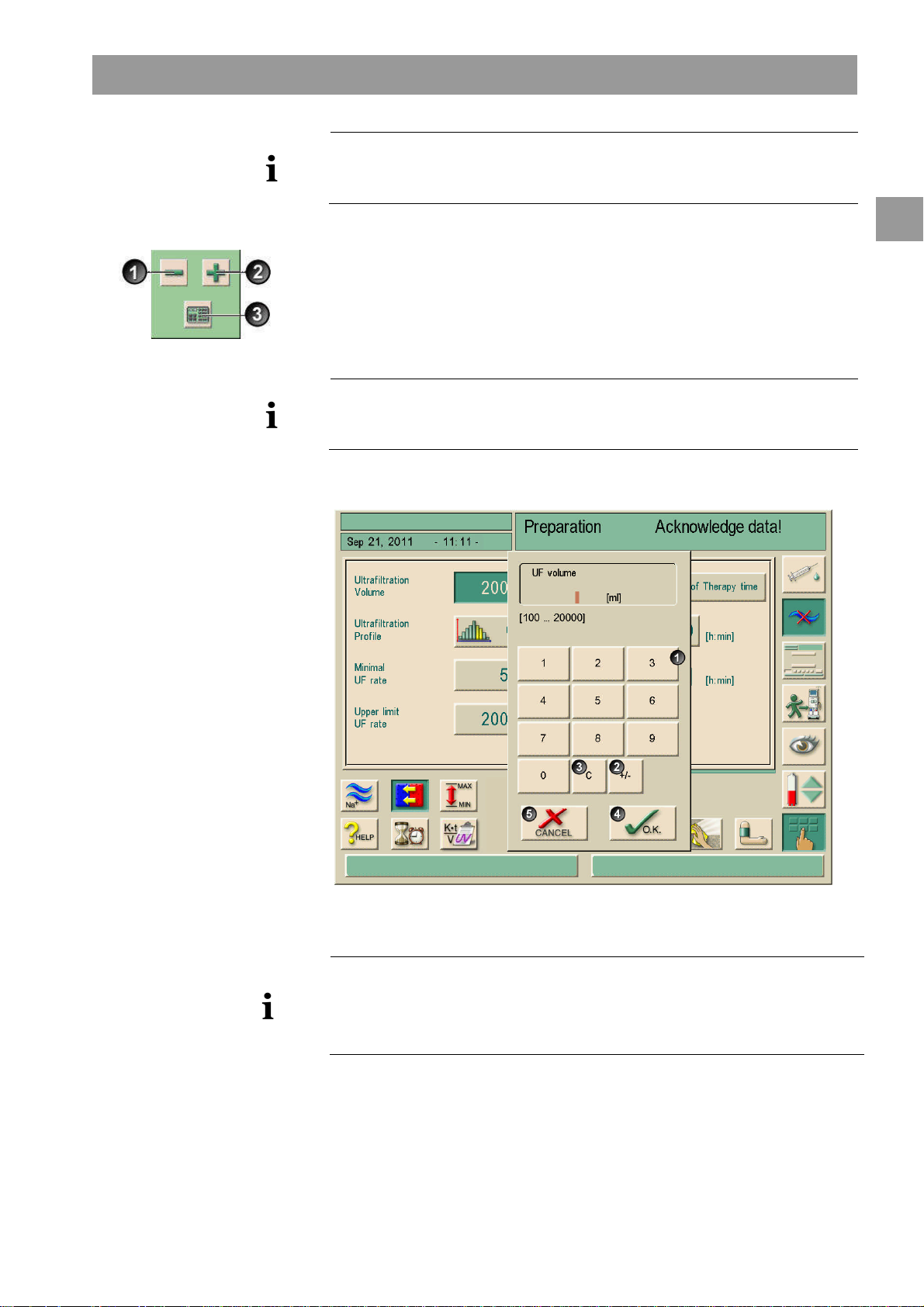
2.6 Entering numerical values
2
The changing of values is based on the same principle for all parameters. We are
therefore providing an example. The example refers to the change of the parameter UF
quantity on the ultrafiltration data window.
Touch icon on window.
The selected icon lights up in green.
An icon appears for all parameter groups that can be changed.
If none of these icons is pressed within a preset time, the icons are switched off
again. The preset time can be set by the service engineer in the service program.
Touch desired icon (shown here: icon for calling up ultrafiltration data window, see
Fig. 2-8).
The selected icon lights up in green.
The preset values for the parameter are displayed.
Touch value to be changed on screen (shown here: value for UF quantity 2000 mL,
see Fig. 2-8).
A field of icons for changing the value is displayed.
The desired value lights up in green.
Legend
Reduce value
1
Increase value
2
Call up keypad for entering
3
values
Example: Calling up
4
”Ultrafiltration data” screen
Fig. 2-8 Icons for changing the value
2-20 IFU 38910363US / Rev. 2.15.10 / May 2016
Page 41
Dialog+® Product description
The dialysis machine can be set in the service program in such a way that a keypad
appears immediately after the value to be changed has been touched. In this case, the
keypad has no O.K. icon. To confirm entry, press on the monitor.
Legend
Numerical keys
1
Change sign of numerical value
2
Delete set numerical value
3
Leave window and accept data
4
Leave window without accepting
5
data
Reduce value: Touch icon 1 until the desired value has been reached.
2
Increase value: Touch icon 2 until the desired value has been reached.
Enter different value: Touch icon 3.
A keypad is displayed. The permissible setting range is specified in square brackets
below the numerical value (shown here: 100 ... 20000, see Fig. 2-9).
By pressing the icons 1 and 2, the setting could be adjusted up or down.
Fig. 2-9 Numerical keypad
Delete the set numerical value: Touch key 3 on keypad.
Interrupt entry of numerical value and return to main window: Touch key 5.
If a value outside the permissible range is entered, the message Limits exceeded is
displayed below the entered value.
Enter value using keypad keys 1.
If necessary, change sign via icon 2.
Confirm entry with icon 4.
IFU 38910363US / Rev. 2.15.10 / May 2016 2-21
Page 42

2
Product description Dialog+®
To access all of the groups of parameters, “shortcuts” can be used. Touch the
parameter which should be changed or a concerning graphic indicator on the main
screen. The corresponding window of the group of parameters will open as shown in
Fig. 2-10.
The following screen shows the available shortcut squares in frames.
Legend
Help icon, active
1
Shortcuts
Fig. 2-10 Shortcut squares during activated help button
If a “shortcut” was touched inadvertently, or if no parameters are entered, the
parameter window will close automatically after 10 seconds.
The frames marking the shortcuts will only appear if the help function is activated.
Touch help button (1).
The “shortcuts“ will be marked by brown frames.
Touch help button again.
The frames disappear.
Shortcuts are only active if the corresponding parameters are relevant for the actual
therapy. For example: The setting of the venous limit can only be done by shortcut
within Single-needle (SN) therapies.
Some shortcuts directly open the +/- window for changing the setting. For example:
UF-quantity.
2-22 IFU 38910363US / Rev. 2.15.10 / May 2016
Page 43
Dialog+® Product description
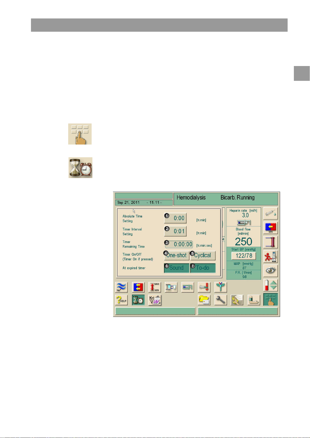
2.7 Using the timer/stop watch
Legend
Adjustment of an absolute time
1
for a warning sound
Adjustment of an interval time
2
for a warning sound
Displays rest or expired time
3
Starts/Stops/resets timer or stop
4
watch
Starts/stops the timer for
5
recurring warnings after input in
1 or 2
Switches off the warning sound
6
after the chosen time interval
Opens an input window for
7
reminder
The Dialog+screen offers a timer or stop watch function for individual use.
These functions are offered in the following phases:
• Preparation
• Therapy
• End of Therapy
• Selection of disinfection
• Disinfection
Touch this icon.
Touch this icon.
The following screen will appear.
2
Fig. 2-11 Timer/stop watch function
If requested, button 6 activates or inactivates the warning sound.
The user could choose between a single warning or a cyclic warning with fixed
intervals.
IFU 38910363US / Rev. 2.15.10 / May 2016 2-23
Page 44

2
Product description Dialog+®
For a single warning
Requested adjustment with button 1 or 2.
Touch button 4 for single warning.
For cyclic warning:
Requested adjustment with button 2 (button 5 automatically activated)
Touch button 5
The timer/stop watch function starts.
To stop/reset touch respective button.
The timer function is counting the time shown in field 3 downwards, the stop watch is
counting upward.
Touch button 7 for input of a reminder.
At expiry of an adjusted time a prompt appears in the message field “The set time
interval expired” or an information window with written reminder appears. The signal
lamps switch to yellow and an acoustic signal appears if it has been activated.
Press the button to acknowledge sound and message.
The timer/stop watch function is not interrupted by a possible power failure.
The running timer/stop watch function is shown with a symbol in the date line of the
screen.
Fig. 2-12 Date line with timer symbol
2-24 IFU 38910363US / Rev. 2.15.10 / May 2016
Page 45

Dialog+® Installation and commissioning
Table of contents
3 Installation and commissioning.......................................................... 3-3
3.1 Scope of supply ....................................................................................3-3
3.2 Storage.................................................................................................. 3-3
3.2.1 Storage in originally packed condition...............................................3-3
3.2.2 Interim storage of devices ready for operation................................3-3
3.2.3 Decommissioning......................................................................................3-3
3.3 Transportation ...................................................................................... 3-4
3.3.1 Rolling..........................................................................................................3-4
3.3.2 Carrying........................................................................................................3-5
3.4 Installation site.....................................................................................3-6
3.4.1 Electrical connection ...............................................................................3-6
3.4.2 Protection against water damage........................................................3-6
3.4.3 Potentially explosive areas.....................................................................3-6
3
3.5 Water supply......................................................................................... 3-7
3.5.1 Quality of water and dialysate..............................................................3-7
3.5.2 Disposal of used fluids.............................................................................3-7
3.6 Initial commissioning........................................................................... 3-8
3.7 Setting date and time..........................................................................3-8
3.8 Switching on and off...........................................................................3-9
IFU 38910363US / Rev. 2.15.10 / May 2016 3-1
Page 46

3
Installation and commissioning Dialog+®
3-2 IFU 38910363US / Rev. 2.15.10 / May 2016
Page 47

Dialog+® Installation and commissioning
3 Installation and commissioning
3.1 Scope of supply
Dialog+dialysis machine
Instructions for Use
Suction tube with screw lid for disinfectant
Tube clamps for tubes
One container lid each with coupling for inserting suction rods (red and blue)
Storage box
• In case of option Central Concentrate Supply: Supply from wall connection coupling
to dialysis machine
Special accessories
Check-in goods
Unpack dialysis machine and check for completeness and damage.
If there is damage, call technical service.
3
3.2 Storage
3.2.1 Storage in originally packed condition
Store the dialysis machine in ambient conditions, as specified in section 15.2.
3.2.2 Interim storage of devices ready for operation
Disinfect the dialysis machine.
Store the dialysis machine in ambient conditions, as specified in section 15.2.
3.2.3 Decommissioning
Disinfect the dialysis machine.
Instruct technical service to empty the dialysis machine.
Store the dialysis machine in ambient conditions, as specified in section 15.2.
IFU 38910363US / Rev. 2.15.10 / May 2016 3-3
Page 48
3
Installation and commissioning Dialog+®
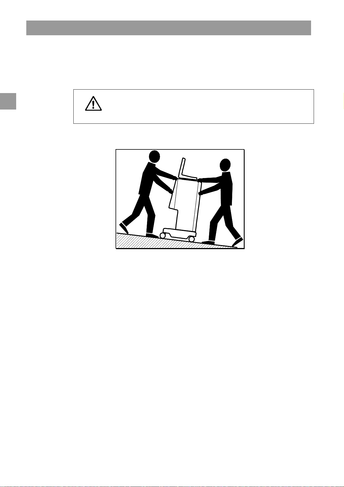
3.3 Transportation
3.3.1 Rolling
Risk of damage if dialysis machine is tilted by more than 10°!
Have 2 or more persons at hand for transporting the machine on stairs and
CAUTION
inclined areas.
Do not tilt the dialysis machine by more than 10°.
Fig. 3-1 Transport on stairs and slopes (2 persons)
Release both brakes of front casters.
Wheel the dialysis machine.
Apply both brakes of front casters.
3-4 IFU 38910363US / Rev. 2.15.10 / May 2016
Page 49

Dialog+® Installation and commissioning
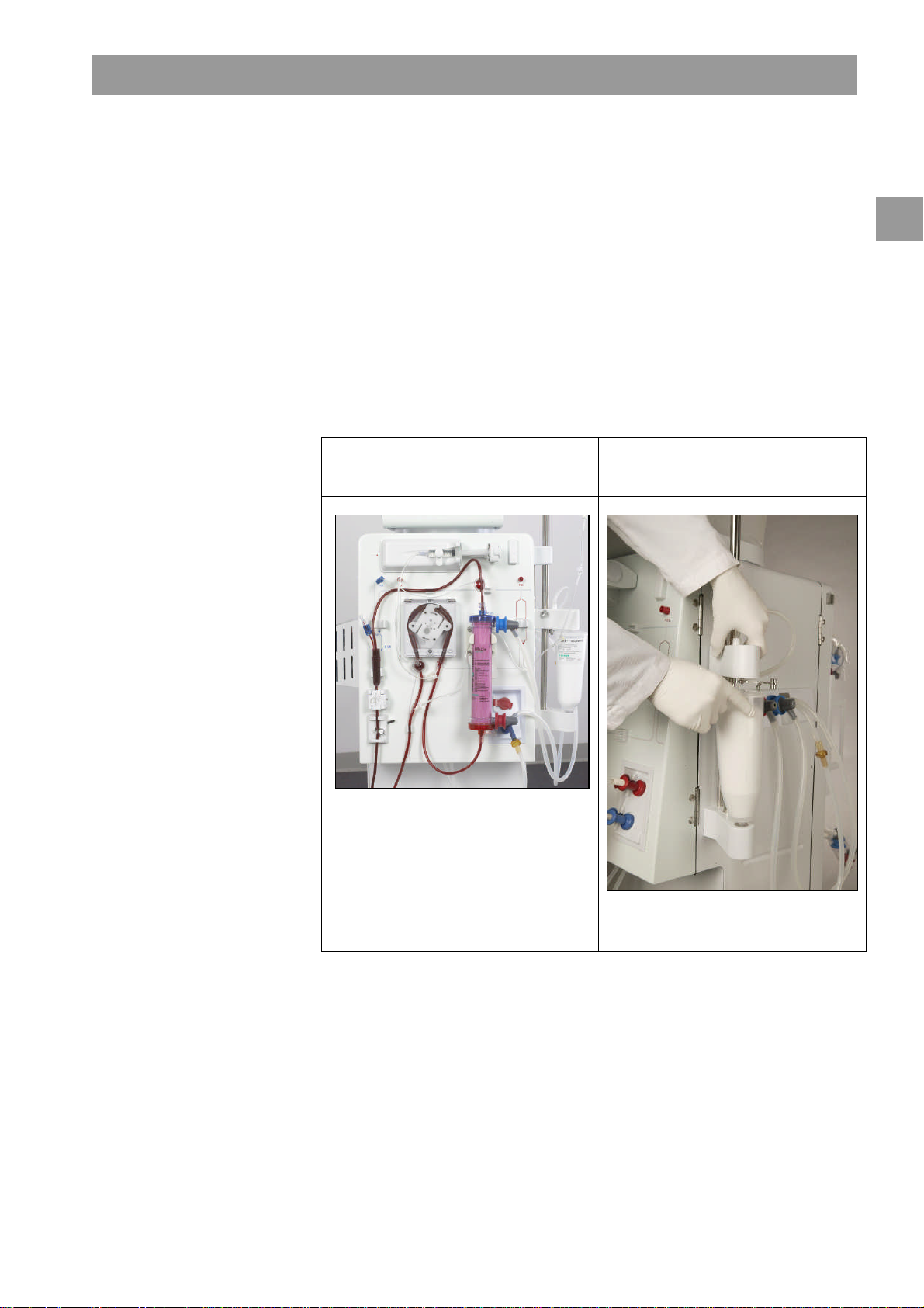
3.3.2 Carrying
For carrying, the dialysis machine can be held at the base, at the rear panel and/or the
protrusion at the front of the machine, as shown in the following illustration.
3
CAUTION
Fig. 3-2 Holding points for carrying the dialysis machine
Danger of damage due to incorrect transportation (wrong holding points)!
Do not hold machine on monitor, on bicarbonate cartridge holder or on
infusion pole when transporting.
Use a belt to secure monitor to infusion pole.
Release caster brakes.
Tilt the dialysis machine.
Put down the dialysis machine.
Apply caster brakes.
IFU 38910363US / Rev. 2.15.10 / May 2016 3-5
Page 50

3
Installation and commissioning Dialog+®
3.4 Installation site
Ambient conditions
Observe information about ambient conditions, see section 15.2.
3.4.1 Electrical connection
The existing mains voltage must correspond with the voltage specified on the rating
plate.
The use of extension cables or adapters with the power cable or the mains socket is
NOT permitted. Modifications of the power cable are forbidden! If the power cable has
to be changed, only the original power cable listed in the spare parts list must be used.
Electrical installations in the room where the dialysis machine will be operated must
conform with relevant regulations, e.g. IEC-stipulations. Regulations and deviations
specific to the individual country must also be observed. For further information, ask
technical service.
Using devices of protection class I the quality of the protective conductor is important.
Regulations and deviations specific to the individual country must also be observed.
For further information, ask technical service.
Each Dialog+machine requires a dedicated 20 amp electrical service, with an isolated
ground.
Grounding reliability can only be achieved when equipment is connected to an
equivalent receptacle marked “hospital only” or “hospital-grade”. North American
medical equipment cords and plugs have to be "hospital-grade" or "hospital only",
meaning they are subject to special requirements contained in relevant applied
standards. It is imperative that the ground connection be reliably maintained to
protect the patient and medical staff. Hospital-grade power cords and cordsets carry
the "green dot" signifying that they have been designed and tested for grounding
reliability, assembly integrity, strength and durability.
3.4.2 Protection against water damage
We recommend the use of water detectors to protect against any unnoticed water
leakages.
3.4.3 Potentially explosive areas
The dialysis machine may not be operated in areas at risk of explosion.
3-6 IFU 38910363US / Rev. 2.15.10 / May 2016
Page 51

Dialog+® Installation and commissioning
3.5 Water supply
3.5.1 Quality of water and dialysate
The user must ensure that the water quality is continuously monitored.
The following requirements must be fulfilled for incoming water:
• Must be free from Mg++and Ca++.
• Must have a pH value between 5 and 7.
Water and dialysate must comply with the country-specific standards, i.e.:
• ISO 13959
Water for haemodialysis and related therapies
ISO 23500
Guidance for the preparation and quality management of fluids for haemodialysis
and related therapies
ISO 11663
Quality of dialysis fluid for haemodialysis and related therapies
3
WARNING
CAUTION
3.5.2 Disposal of used fluids
Risk of infection due to backflow of contaminated fluids from the drain into the
dialysis machine!
Ensure air clearance between hemodialysis equipment waste connector and the
drain (8 cm).
Pipe system may be damaged by corrosive fluids!
Use adequate drainage piping materials.
Ensure sufficient drainage capacity!
IFU 38910363US / Rev. 2.15.10 / May 2016 3-7
Page 52

3
Installation and commissioning Dialog+®
3.6 Initial commissioning
Initial commissioning should be carried out by the responsible technical service.
3.7 Setting date and time
Fig. 3-3 Date and time
Setting date
Touch field showing date and time 1.
The field containing icons 2, 3 and 4 appears.
There are two setting options:
To increase or decrease the date, change date with icons 2 and 3.
To enter the date using the keypad, touch icon 4.
The numeric keypad appears on the screen.
Enter date using keypad and confirm by selecting OK.
Setting time
Touch field containing date and time 1.
There are two setting options.
To increase or decrease time by minutes, change date with icons 2 and 3.
To enter the time using the keypad, touch icon 4.
The numeric keypad appears on the screen.
Enter date using keypad and confirm by selecting OK.
Touch field containing date and time 1.
The field containing 2, 3 and 4 disappears.
The set date and time are displayed.
3-8 IFU 38910363US / Rev. 2.15.10 / May 2016
Page 53
Dialog+® Installation and commissioning
3.8 Switching on and off
• In case of any damage that may put into question the safe use of the machine, the
dialysis machine must not be used. Inform customer service.
Only switch on dialysis machine after it has reached room temperature.
Observe requirements on installation site and water supply.
Switching on and off
Press mains switch.
The dialysis machine switches from ON to OFF status or vice versa.
Accidental pressing of the mains switch
In case of accidentally switching off the dialysis machine by pressing the power switch
during a dialysis session, proceed as follows:
Press power switch again.
An alarm message is displayed on the screen, “System recovered”, for interruptions
less than 15 minutes, and the therapy continues.
Confirm alarm by pressing ”Confirm alarm”.
In case of interruptions lasting no longer than 15 minutes, therapy continues. In
case of longer interruptions, the dialysis machine switches to the therapy selection
window.
3
In case of accidentally switching off the dialysis machine by actuating the power
switch during disinfection, proceed as follows:
Press the power switch again.
The disinfection process is continued.
In case of accidentally switching off the machine a characteristic signal rings out
three times.
IFU 38910363US / Rev. 2.15.10 / May 2016 3-9
Page 54

3
Installation and commissioning Dialog+®
3-10 IFU 38910363US / Rev. 2.15.10 / May 2016
Page 55

Dialog+® Therapy types
Table of contents
4 Therapy types ....................................................................................... 4-3
4.1 Hemodialysis (HD) ................................................................................ 4-3
4.2 Phases of pure ultrafiltration ............................................................. 4-3
4.3 Methods of treatment......................................................................... 4-4
4.3.1 Double-needle procedure .......................................................................4-4
4.3.2 Single-needle procedure.........................................................................4-4
4.4 Effectiveness of dialysis (Kt/V)........................................................... 4-5
4
IFU 38910363US / Rev. 2.15.10 / May 2016 4-1
Page 56

4
Therapy types Dialog+®
4-2 IFU 38910363US / Rev. 2.15.10 / May 2016
Page 57

Dialog+® Therapy types
4 Therapy types
4.1 Hemodialysis (HD)
Hemodialysis is the most common type of therapy used for cleaning blood. Depending
on clinical requirements, treatment generally lasts between three and six hours
(typically 4 hours). The procedure is carried out three times a week (in exceptional
cases, twice a week).
Mode of operation
The dialysis machine pumps blood through a vascular access from the patient into the
dialyzer.
Inside the dialyzer, metabolic waste products are separated from the blood. The
dialyzer operates as a filter that is divided into two parts by a semipermeable
membrane. On one side, the patient's blood is pumped past, on the other side the
dialysate flows past.
During the therapy, the dialysate is prepared by the dialysis machine. It consists of
prepared water to which certain quantities of electrolyte and bicarbonate, depending
on the individual patient’s requirements, are added.
The concentrations of electrolyte and bicarbonate in the dialysate are adjusted in such
a way that certain substances can be removed from the blood through convection,
diffusion and osmosis, while other substances are added at the same time. This is
achieved mainly by diffusive clearance through the semipermeable membrane of the
dialyzer. The dialysate transports the metabolic waste products from the dialyzer into
the discharge line. The cleaned blood is then recycled back to the patient.
During treatment, the dialysis machine monitors blood circulation outside of the body,
pumps blood and dialysate in separate circulation systems through the dialyzer and
monitors the composition and volume balance of the dialysate.
The heparin pump, which is also part of the dialysis machine, is used to add
anticoagulants to the blood so as to prevent the formation of blood clots.
In addition to cleaning metabolic waste from the blood, the dialysis machine removes
water from the blood, which would be excreted through the kidney in healthy humans.
4
4.2 Phases of pure ultrafiltration
Phases of pure ultrafiltration are used for short-term extraction of a higher amount of
fluid from the patient.
For further information see section 10.
Mode of operation
During phases of pure ultrafiltration no dialysate flows through the dialyzer. The
purpose of this therapy is to extract fluid from the patient.
IFU 38910363US / Rev. 2.15.10 / May 2016 4-3
Page 58
4
Therapy types Dialog+®
4.3 Methods of treatment
4.3.1 Double-needle procedure
The double-needle procedure is the standard technique in hemodialysis. Blood is
extracted from the patient through the arterial vascular access. The blood pump
continuously pumps the blood through the arterial tubing system to the dialyzer.
There, the exchange of metabolic waste products between the blood and the dialysate
proceeds through the semipermeable membrane of the dialyzer. After that, the blood
is taken back through the venous tubing system, the bubble trap and a second
vascular access to the vein.
4.3.2 Single-needle procedure
The single-needle procedure is applied when patients experience problems with the
predominantly used double-needle dialysis. In the single-needle procedure only one
needle (single-needle cannula) or a single-lumen, single-needle catheter is applied to
the patient. The arterial and venous ends of the tubing system are connected via a
Y-connector. This procedure allows reducing the number of punctures by half
compared to double-needle dialysis, thus preserving the patient's shunt.
The single-needle clamp procedure allows ending a running double-needle dialysis in
case of problems (e.g. at the shunt). The single-needle clamp procedure requires only
one blood pump but can also be applied to a dialysis machine containing two pumps.
The second blood pump remains switched off in this case. See chapter 9 for a
complete description of the single-needle procedure.
Single-needle is not available with the use of Streamline® Bloodlines.
Mode of operation
The patient is connected through either a ”standard AV set with 30 mL chamber” or an
”AV set for SN clamp with a 100 mL chamber”. The arterial and venous blood lines are
connected through a Y-connector at the vascular access.
With the venous tube clamp closed and the arterial tube clamp (if present) open, the
blood pump pumps blood from the patient through the dialyzer into the venous
chamber. The pressure in the venous chamber is monitored via the venous pressure
absorber. As soon as the preset upper switching pressure is reached, the blood pump is
switched off and the venous tube clamp opens. If an arterial tube clamp is installed
also, this clamp closes and thereby blocks any recirculation of blood into the arterial
tube between Y-connector and blood pump.
Due to the pressure in the venous chamber, the blood flows through the dialyzer back
to the patient until the lower switching pressure is reached. Once the lower switching
pressure has been reached in the venous chamber, or the preset return flow time has
expired, the venous tube clamp closes. Shortly afterwards the arterial tube clamp (if
present) opens. The blood pump is activated and the process starts again with the
withdrawal of blood from the patient.
The return flow time is averaged over the first three cycles and automatically set
between 3 and 10 seconds for the duration of the therapy. If the lower switching
pressure was not reached, the machine switches to the arterial phase after 10 seconds.
4-4 IFU 38910363US / Rev. 2.15.10 / May 2016
Page 59
Dialog+® Therapy types
4.4 Effectiveness of dialysis (Kt/V)
If the theoretical calculation of the effectiveness is selected, the option AdimeaTMas
described in chapter 10.4 is not applicable.
WARNING
The dialysis machine allows optimization of therapy over many treatments. For this
purpose, the theoretical effectiveness is calculated by the dialysis machine. This
theoretical figure can then be compared with the actual effectiveness determined
from blood samples.
For actual effectiveness, patient urea values before and after dialysis have to be
determined in the laboratory and entered into the dialysis machine. (Only available
while using therapy card system.)
Comparison of theoretical and actual effectiveness over many treatments
The comparison of theoretical and actual effectiveness can be used as a decision aid
for setting the therapy parameters and for selecting the dialyzer. Using the patient
therapy card, the dialysis machine can store and list the figures for the last
50 treatments.
Risk to the patient by the input of new treatment parameters.
The treatment parameters may not be determined solely on the basis of the
measured Kt/V.
A measurement of the Kt/V does not replace the therapy prescribed by the
physician.
Monitoring the effectiveness during the current treatment
During a treatment, the current effectiveness estimated by the dialysis machine can
also be used as an indicator for the effectiveness that would be achieved if the
treatment would be terminated at a specific time.
The warning during treatment that a certain target value for the effectiveness (Kt/V
value), which was determined prior to treatment, cannot be reached, allows early
corrective intervention into the running treatment.
4
It cannot be guaranteed that the calculated Kt/V value will actually be reached.
Calculation during particular phases
The Kt/V value is not calculated during:
• Sequential phases of profiles
• Hemofiltration
• Infusion bolus, as the actual blood flow does not correspond to the blood pump
speed
During a phase at a min. UF rate, the Kt/V value calculation is continued. During a
single-needle dialysis, the Kt/V value calculation is based on the average blood flow.
IFU 38910363US / Rev. 2.15.10 / May 2016 4-5
Page 60

4
Therapy types Dialog+®
4-6 IFU 38910363US / Rev. 2.15.10 / May 2016
Page 61

Dialog+® Preparing for hemodialysis
Table of contents
5 Preparing for hemodialysis ................................................................. 5-3
5.1 Initiating hemodialysis......................................................................... 5-4
5.2 Automatic test...................................................................................... 5-4
5.2.1 Operation during automatic test..........................................................5-5
5.2.2 Terminating the automatic test sequence.........................................5-6
5.2.3 Completion of automatic test sequence............................................5-6
5.3 Reducing the warning sounds during preparation............................5-6
5.4 Connecting the concentrate ............................................................... 5-8
5.5 Setting the rinsing parameters........................................................... 5-9
5.6 Inserting, rinsing and testing the tubing system............................5-11
5.6.1 Inserting standard A/V tubing............................................................5-12
5.6.2 Rinsing and testing standard A/V tubing........................................5-14
5.6.3 Level regulation during Preparation (if present)...........................5-14
5.6.4 Inserting Streamline® bloodline.........................................................5-16
5.6.5 Rinsing and testing the tubing system............................................5-17
5
5.7 Preparing the heparin pump .............................................................5-18
5.7.1 Inserting the heparin syringe..............................................................5-18
5.7.2 Venting the heparin line......................................................................5-19
5.8 Setting the treatment parameters...................................................5-20
5.8.1 Setting the dialysate parameters ......................................................5-21
5.8.2 Monitoring the dialysate.....................................................................5-24
5.8.3 Sampling of dialysate for microbiology analysis ..........................5-25
5.8.4 Setting the ultrafiltration parameters .............................................5-27
5.8.5 Setting the pressure limits..................................................................5-29
5.8.6 Setting the heparin parameters.........................................................5-31
5.9 Rinsing the dialyzer............................................................................5-33
5.9.1 Rinsing the dialyzer using standard A/V tubing............................5-33
5.9.2 Rinsing the dialyzer using Streamline® bloodline........................5-34
5.10 Stand-by mode...................................................................................5-35
5.10.1 Activating the stand-by mode ...........................................................5-35
5.10.2 Switching off the stand-by mode.....................................................5-35
5.11 Power failure in preparation.............................................................5-36
5.12 Changing the bicarbonate cartridge during preparation...............5-36
IFU 38910363US / Rev. 2.15.10 / May 2016 5-1
Page 62

5
Preparing for hemodialysis Dialog+®
5-2 IFU 38910363US / Rev. 2.15.10 / May 2016
Page 63
Dialog+® Preparing for hemodialysis
5 Preparing for hemodialysis
Safety air detector (SAD) not active! Danger of air embolism!
Do not connect the patient out of the “Therapy” phase, e. g. during
“Preparation/Disinfection” phase!
WARNING
Do not use the blood pump for infusion outside the “Therapy” phase, e.g.
during the saline infusion.
WARNING
WARNING
Hemodialysis is the standard dialysis procedure for all system variants.
The procedure is the same for all system variants.
Loss of blood or damage of blood by temperature, pressure or wrong composition
of dialysis fluid!
Ensure that the patient will only be connected in the “Therapy” phase.
Do not have the patient connected in any other phase but the “Therapy”
phase, e.g. during the “Preparation/Disinfection” phase!
Do not use the blood pump for infusion outside the “Therapy” phase, e.g.
during the saline infusion.
Connecting the patient in “Preparation/Disinfection” generates an alarm by the red
detector. This results in the blood pump stopping and SAKV closing.
Risk to the patient due to blood loss.
When the blood flow stops, because of blood pump failure during loss of mains
power, blood clotting could cause blood loss.
Return blood to patient manually (see chapter 13.4.).
5
IFU 38910363US / Rev. 2.15.10 / May 2016 5-3
Page 64

5
Preparing for hemodialysis Dialog+®
5.1 Initiating hemodialysis
After switch-on, the following main screen is displayed on the dialysis machine:
Fig. 5-1 "Hemodialysis" main screen
Touch field 1.
The first preparation screen for hemodialysis appears. The dialysis machine starts an
automatic test sequence.
5.2 Automatic test
At the automatic test stage, the dialysis machine automatically checks all control
functions relevant to the safety of the machine.
While the dialysis machine is carrying out automatic tests, you can begin entering the
i
treatment parameters.
If the option “Bloodside pressure test with pressure compensation“ is activated in TSM
the excess pressure in the A/V system will be dissipated through the dialyzer after the
pressure test on the blood side.
Depending on the type of dialyzer used, this may take up to two minutes.
5-4 IFU 38910363US / Rev. 2.15.10 / May 2016
Page 65

Dialog+® Preparing for hemodialysis
5.2.1 Operation during automatic test
Legend
Status field
1
Operating field
2
5
Fig. 5-2 First preparation screen "Hemodialysis"
While the dialysis machine goes through the automatic test sequence, messages on a
yellow background appear in field 2 if the machine expects you to carry out actions,
such as connecting the concentrate. The test sequence is continued once this action
has been completed.
Fig. 5-3 Information window during automatic test
Information windows can be hidden by a touch for approx. 20 seconds while you use
the screen for other actions, e.g. entering parameters. Upon completion of the entry,
the information window will reappear. Saving the data with the Enter button will
only be possible after confirming the information window.
IFU 38910363US / Rev. 2.15.10 / May 2016 5-5
Page 66

5
ID
Text
Preparing for hemodialysis Dialog+®
5.2.2 Terminating the automatic test sequence
Touch icon.
The automatic test sequence is terminated.
The options "Return to therapy selection" and "Repeat blood-side tests" are displayed.
Touch the appropriate field.
5.2.3 Completion of automatic test sequence
This icon is enabled as soon as the dialysis machine has completed all automatic tests
and the bloodline tests.
In case of use of dialyzers packed with germicide, the rinse program should be
completed and the dialyzer tested for residual sterilant prior to changing to the
WARNING
therapy phase.
5.3 Reducing the warning sounds during preparation
For the user there is a possibility to suppress some warning sounds during preparation.
Warning sounds during preparation which require interaction with the user may not
be suppressed. Examples of these warning sounds are fault removal or on demand for
action. Optical alarms and the fault finding are not affected.
The function “Reduced warning sounds during preparation“ can be used for the
following warnings.
1927 Rinsing volume attained
1928 Filling volume is reached
1112 UF Rinse volume for dialyzer too high
1153 Repeat self test!
1033 Temperature too low
1034 Temperature too high
1038 Connect acid/acetate concentrate
1040 Connect bicarbonate
1041 Connect blue concentrate coupling to rinse bridge
1045 Bicarbonate cartridge holder open
Preparing the machine with reduced warning sounds could cause a delay of the
treatment. Scheduling planned preparation time requires increased attention of the
staff.
5-6 IFU 38910363US / Rev. 2.15.10 / May 2016
Page 67

Dialog+® Preparing for hemodialysis
Fig. 5-4 "Hemodialysis" main screen
5
Touch icon at main screen.
The following screen is displayed:
Fig. 5-5 Screen for suppression of acoustic Signals
Touch icon.
IFU 38910363US / Rev. 2.15.10 / May 2016 5-7
Page 68

Preparing for hemodialysis Dialog+®
If a function is not active (icon background not colored in green) it may be activated
by touching the icon. The warning sounds listed in the table above are automatically
suppressed. To indicate this, a crossed out speaker symbol appears at the date line of
the screen.
Fig. 5-6 Date line with suppressed acoustic signal
5
WARNING
Now the icon is shown as active (green colored background).
Touching the icon once more inactivates the function and turns on audible signals for
the warning sounds listed above. The indicator at the date line disappears.
The function “Reduced warning sounds during preparation“ could be preset in the
TSM-mode by a technician.
The function “Reduced warning sounds during preparation“ is only available during
program selection and preparation and can be configured during selection of program
and preparation. For all other phases of treatment this function is not available (icon
appears grey). Changing into the next therapy the function automatically set resets to
the TSM-preadjustment.
5.4 Connecting the concentrate
On completion of the internal pressure test, the request connect acetate/acid
concentrate appears on a yellow background.
Risk to the patient due to incorrect composition of dialysate!
Ensure that the correct concentrates are provided for the intended therapy.
Only use concentrates whose printed use-by date has not expired.
Only use originally closed and intact concentrate containers.
Observe storage information on concentrate containers.
It is recommended to use concentrates produced by B. Braun Medical Inc.
When concentrates are used that are not produced by B. Braun Medical Inc.
the correct mixing ratio and composition has to be checked on the
concentrate label.
The physician in charge is responsible for determining the concentrates to be used.
5-8 IFU 38910363US / Rev. 2.15.10 / May 2016
Page 69

Dialog+® Preparing for hemodialysis
For bicarbonate dialysis:
Insert red concentrate rod into the canister containing acidic bicarbonate
concentrate, e.g. SW 325A.
Insert blue concentrate rod into the canister containing alkaline bicarbonate
concentrate, e.g. bicarbonate-containing solution 8.4%.
The dialysis machine continues the automatic test sequence.
For acetate dialysis:
Place concentrate rod marked in red and white into container filled with acetate
concentrate, e.g. SW 44.
Leave blue concentrate rod in blue concentrate rod holder.
The dialysis machine continues the automatic test sequence.
5.5 Setting the rinsing parameters
This option allows rinsing of the dialyzer membrane with or without ultrafiltration.
To call up simultaneous ultrafiltration:
Touch icon in preparation window.
The rinsing parameters are displayed.
5
Fig. 5-7 ”Rinsing parameters” screen
IFU 38910363US / Rev. 2.15.10 / May 2016 5-9
Page 70

Preparing for hemodialysis Dialog+®
Item
Text
Range
Description
Set the values intended for rinsing parameters according to dialyzer manufacturer
recommendations and the table below.
5
1 AV system
filling/rinsing
2 Filling BP rate 50 – 600 mL/min The rate with which the
3 Filling BP volume 0 – 6000 mL The blood pump stops after it
4 Rinsing with
ultrafiltration
5 Rinsing BP rate 50– 300 mL/min BP rate for rinsing program
6 Dialysate flow 300 – 800 mL/min DF rate for rinsing program
7 Rinsing time 0 – 59 min Duration of adjusted rinsing
8 UF rate for rinsing 0 – 3000 mL/h when rinsing
with a physiological saline
solution
9 UF-volume f. rinsing 0 – 2950 mL when rinsing
with a physiological saline
solution
10 Blood flow for
connecting patient
50 – 600 mL/min
–
–
Rinse blood side
blood side is filled or rinsed
has rinsed the blood side
using the set volume
Rinsing of dialyzer
membrane
program
–
–
–
Confirm all settings by pressing the O.K. icon.
The initial preparation window reappears, at the end of the chosen rinsing time the
yellow signal lamp flashes.
5-10 IFU 38910363US / Rev. 2.15.10 / May 2016
Page 71

Dialog+® Preparing for hemodialysis
5.6 Inserting, rinsing and testing the tubing system
The used blood pump tubing segment in the AV system must have the dimensions
8 x 12 mm (inner/outer dimension).
Risk to patient due to incompatibility of tubing system and dialysis machine!
WARNING
WARNING
Only use disposables supplied by B. Braun Medical Inc.
Risk to patient due to hemolysis or blood loss when using a faulty blood tubing
system!
Check to ensure that the tubing system is not damaged.
Check to ensure that no line is kinked.
Make certain that all connections are tightly sealed.
5
WARNING
WARNING
Risk to patient due to infection as a result of contamination of the transducer
protector on the tubing system!
Replace the machine-side transducer protector if it has been contaminated
with blood.
Instruct technical service to replace transducer protector, tubing and pressure
port.
Execute disinfection after replacement.
Only use the machine again when the filter has been changed.
Risk of contamination at the patient connectors on the blood tubing system
when using a rinsing bucket!
Ensure aseptic technique in handling of the blood lines.
IFU 38910363US / Rev. 2.15.10 / May 2016 5-11
Page 72

5
Venous tubing
Venous chamber
Venous pressure transducer
Preparing for hemodialysis Dialog+®
5.6.1 Inserting standard A/V tubing
Legend
1
Safety air detector with venous
2
red detector
3
4
Arterial pressure transducer
5
Arterial blood pump
6
Heparin pump
7
PBE-Pressure transducer for
8
arterial entry pressure at the
dialysis machine (option)
Arterial chamber
9
Dialyzer
10
valve
Fig. 5-8 Schematic view of extracorporeal circulation system used in hemodialysis
A dialyzer holder that can be attached to the infusion pole above the top fixture is
available as an accessory.
To swivel or shift the dialyzer holder, always loosen the screw clamp on the infusion
pole so that the latter will not be damaged.
Fix dialyzer in dialyzer holder.
Attach bag containing physiological saline solution (up to 2.5 kg) to infusion pole.
Connect arterial connection of blood tubing system to bag containing the
physiological saline solution. Do not break the seal yet.
If present: Connect pressure measuring line for arterial pressure to the PA pressure
sensor.
Open lid (left, if using a double pump dialysis machine) of blood pump.
Insert tubing end with patient supply into the matching opening of the rotor.
Turn rotor in direction of arrow to thread blood pump segment into pump.
5-12 IFU 38910363US / Rev. 2.15.10 / May 2016
Page 73

Dialog+® Preparing for hemodialysis
Risk to patient due to blood loss when using a faulty blood tubing system!
Check to ensure that the tubing system and pump segments are not being
damaged at insertion.
Check to ensure the pump segment is fully inserted into the respective tubing
CAUTION
guide at the blood pump.
When inserting the pump segments do not rotate the rollers against a drag.
If the tubing system has been damaged through the insertion, replace it with a
new one.
CAUTION
Close lid (left) of blood pump
The spacers on the inside of the lid are not designed for placement of the pump
segment in the right position. They prevent the pump segment from moving out of the
proper position during operation therefore preventing only damage to the rollers.
Connect pressure transducer connector (if present), to PBE sensor connection.
Connect arterial and venous tubing system to dialyzer, observing color-coding. Do
not yet remove the stops on the lateral Hansen connectors.
Connect pressure measuring line for venous pressure to PV pressure sensor, making
certain the pressure measuring line is not kinked and the filter is securely seated.
Insert venous bubble trap into fixture.
Open lid of air detector.
Insert tubing into air detector and close lid.
Connect venous patient connection to the rinse bucket.
Insert blood tubing system into fixtures.
Risk of damage to the tubing system due to prolonged clamping of the venous
blood line!
Only place the venous blood line into the tubing clamp (SAK) on therapy day.
5
If a tubing system without PBE sensor is used, the message "PBE not connected" is
displayed during the pressure test.
The message automatically disappears after 60 seconds.
IFU 38910363US / Rev. 2.15.10 / May 2016 5-13
Page 74
Preparing for hemodialysis Dialog+®
Risk of contamination of the priming bag if administration set is connected and
blood side pressure test fails because of a wet transducer protector membrane!
Set level in the drip chamber of the administration set.
WARNING
If there is no air inside the drip chamber, change priming bag because of
possible contamination.
Change priming bag in case of blood side pressure test failure.
5.6.2 Rinsing and testing standard A/V tubing
5
Break the seal of the bag containing physiological saline solution.
Start the blood pump by pressing the + button on the keypad.
The tubing system will fill with physiological saline solution. The blood side of the
dialysis circuit is rinsed and automatically tested for any leakages.
During the priming procedure, both the arterial and venous patient connection lines
can be placed in the holders located on the inside top of the rinse bucket. Lines should
be placed to prevent the ends from touching the waste product with both vented end
caps intact.
Prior to patient connection, if fresh saline is to replace the recirculated saline, the
arterial line can be held above the rinse bucket, being careful not to touch the bucket.
Once the saline in the arterial portion of the line is replaced, it may be connected to
the patient but left clamped. The venous blood line may be placed in the line holder in
the bucket with the vented end cap in place to prevent contamination of the patient
connection during saline replacement. After the treatment has been initiated, the
rinse bucket should be emptied and rinsed with clean water and returned to the
machine.
5.6.3 Level regulation during Preparation (if present)
The level regulation system allows the user to set saline levels in the blood line
chambers for preparation by screen touch.
• During Preparation the levels can only be set while the blood pump is running.
• The user is obligated to check for correct setting of the levels in the chambers.
Touch icon
The level window opens.
5-14 IFU 38910363US / Rev. 2.15.10 / May 2016
Page 75
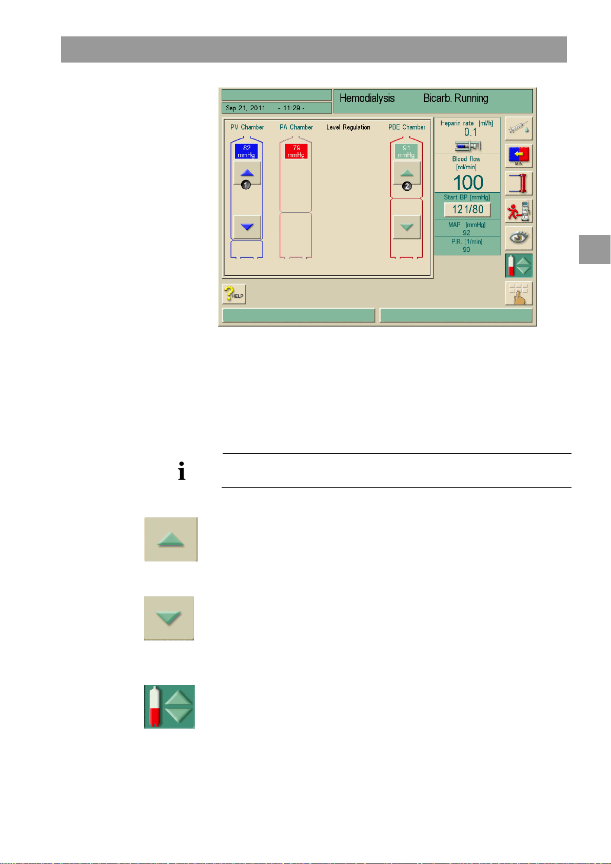
Dialog+® Preparing for hemodialysis
Legend
1
2
PV - Venous chamber
PBE – Arterial blood
entry chamber
Fig. 5-9 Level regulation screen (if present)
5
The setting of the following chambers is possible:
Venous chamber (PV) (1): the button is always active.
Arterial blood entry chamber (PBE) (2): the button is always active (if selected in
TSM).
The adjustment of the PBE chamber is only possible if an AV system with PBE line is
used and the line is connected to the machine.
Level increasing
Touch icon gently with one touch.
Observe level.
Touch again for the correct setting if necessary.
Level decreasing
Touch icon gently with one touch.
Observe level.
Touch again for the correct setting if necessary.
To leave the level regulation function, touch icon again.
IFU 38910363US / Rev. 2.15.10 / May 2016 5-15
Page 76

5
Preparing for hemodialysis Dialog+®
5.6.4 Inserting Streamline® bloodline
For further information about the use of Streamline® bloodline, please refer to the
instructions for use provided by the manufacturer.
Remove lines from pouch.
Take blue venous blood line in hand.
Remove the line tape.
Place venous patient connector into rinse receptacle, do not close any clamps or
open any end caps.
Remove the dialyzer from its holder to connect the venous dialyzer connector end
to prevent kinking the line where it joins the pod. Try to have the venous pod facing
forward for better visualization and to prevent kinking the monitor line.
Connect the venous pod monitoring line to the VP monitor site.
Place the venous drip chamber into the chamber holder.
Position the venous line into the air detector housing and venous line clamp.
Close air detector housing door firmly.
Take red arterial line in hand.
Remove large line tape leaving the small infusion line tape in place. Place the
patient connector into the rinse receptacle, clamping nothing. End caps are vented
for easy priming without contamination.
Place the arterial pod below the left lower end of the blood pump housing and turn
the blood pump until the blood pump segment is caught but not occluded.
Untape the infusion line and spike saline with all clamps open.
Prime the arterial line and heparin line by gravity expelling air from both the
arterial patient connector end and dialyzer end of the tubing. Clamp large red line
clamp.
Clamp upper saline infusion line clamp.
Clamp the heparin infusion line located to the right of the blood pump.
Connect dialyzer end to the dialyzer, unclamp upper saline infusion line clamp and
finish loading the blood pump segment by hand.
Close blood pump door and connect the arterial pod monitor line to the AP monitor
site. No transducer protector is needed. Inspect lines and pods for position and
kinking.
5-16 IFU 38910363US / Rev. 2.15.10 / May 2016
Page 77
Dialog+® Preparing for hemodialysis
5.6.5 Rinsing and testing the tubing system
Increase blood pump speed as per dialyzer manufacturer recommendations to
complete priming.
Once the saline has filled the venous blood line past the drip chamber, open the
vent line at the top of the drip chamber and fill the chamber and the vent line
completely. Clamp the vent line.
When the blood pump stops, connect the arterial and venous patient ends for
recirculation and restart the blood pump. The membrane inside the pods should be
moving slightly when the blood pump is running. The faster the blood pump speed,
the more movement.
Medication administration sites: On the saline infusion line there is one Locksite®
and one injection port.
The venous drip chamber has the standard luer-lock connector for medication
administration but caution must be used to avoid introduction of air into the
system.
The arterial line has a locksite located near the patient connection, but this is
usually used for blood draws rather than medication administration.
PBE cannot be utilized with Streamline® bloodlines.
Single needle cannot be performed using Streamline bloodlines.
See the Trouble Shooting Guide if blood side testing fails due to misaligned pod
diaphragm.
5
IFU 38910363US / Rev. 2.15.10 / May 2016 5-17
Page 78
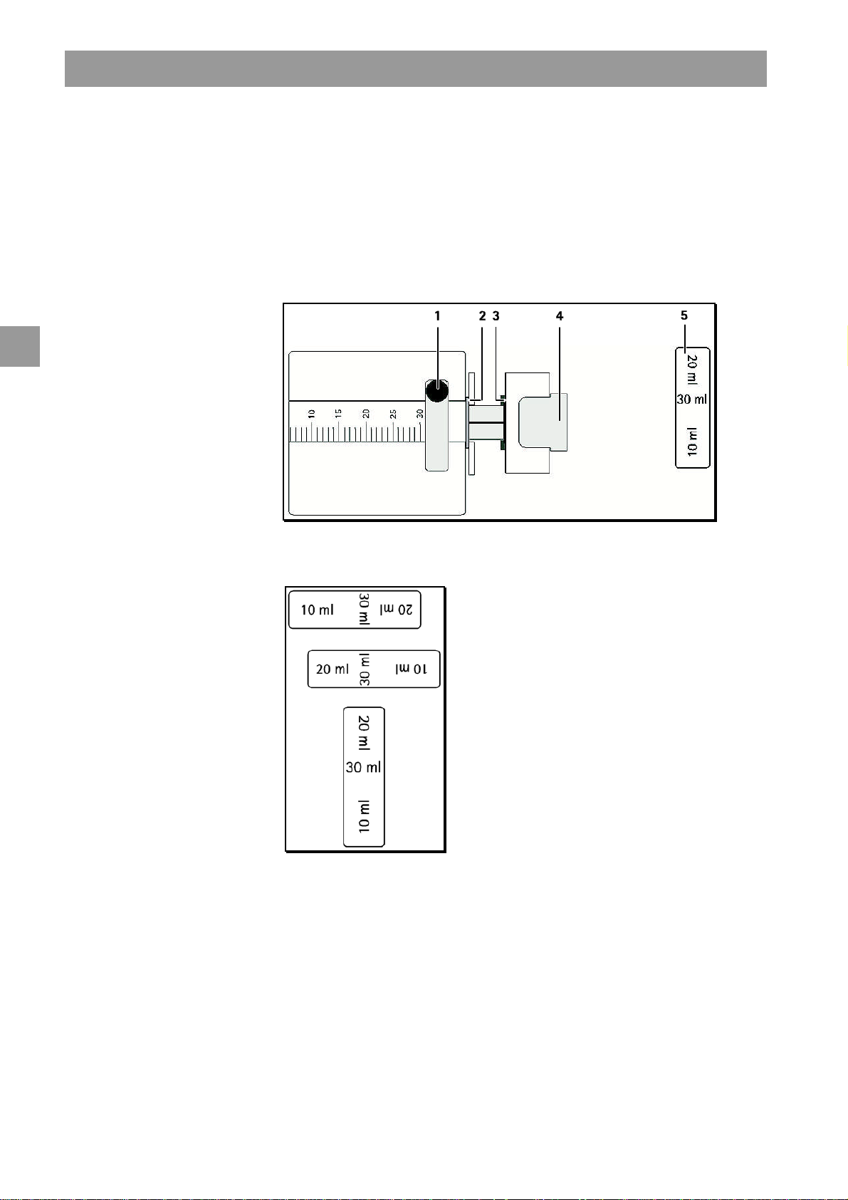
5
Preparing for hemodialysis Dialog+®
5.7 Preparing the heparin pump
The heparin pump is suitable for tubing systems with heparinization downstream of
the blood pump in the positive pressure region.
5.7.1 Inserting the heparin syringe
Legend
Syringe bracket
1
Syringe gripping plate
2
Clip
3
Unlocking lever
4
Syringe stop
5
Fig. 5-10 Heparin syringe
Fig. 5-11 Position of the syringe stop depending on syringe size
5-18 IFU 38910363US / Rev. 2.15.10 / May 2016
Page 79

Dialog+® Preparing for hemodialysis
Set syringe stop (5) in such a way that the syringe size can be read.
Release unlocking lever (4) and pull out drive mechanism.
Lift and turn syringe bow (1).
Insert syringe in such a way that grip and pressure plate engage in the guide.
If the syringe was inserted correctly, the unlocking mechanism will jump back
automatically. Do not close the unlocking mechanism manually.
Close syringe bracket.
5.7.2 Venting the heparin line
Before inserting the syringe, manually vent heparin line.
or
Vent heparin line prior to starting the dialysis by providing a heparin bolus.
5
IFU 38910363US / Rev. 2.15.10 / May 2016 5-19
Page 80

5
Preparing for hemodialysis Dialog+®
5.8 Setting the treatment parameters
Touch icon in preparation window.
A line of additional icons (1) is displayed.
Fig. 5-12 Preparation window "Parameters"
Icon reference:
Icon Parameter group Reference
Dialysate parameters
Ultrafiltration parameters
Pressure limit settings
Heparinization data
Page 5-21
Page 5-21
Page 5-29
Page 5-31
5-20 IFU 38910363US / Rev. 2.15.10 / May 2016
Page 81

Dialog+® Preparing for hemodialysis
5.8.1 Setting the dialysate parameters
Touch icon in preparation window.
If Acetate is activated in TSM, the following dialysate parameters are displayed.
5
Fig. 5-13 "Dialysate parameters" screen (if acetate is activated in TSM)
Set dialysate parameters according to the following table.
Item Text Range Description
1 Conductivity 12.5–16.0mS/cm in steps of
0.1 mS/cm (approx. 125–160
2 Bicarbonate
–
3 Acetate
4 Bicarbonate
Conductivity
5 Dialysis fluid
Temperature
2–4 mS/cm in steps of
0.1 mS/cm
33–40 °C in steps of 0.5 °C
or manual entry in steps of
0.1 °C /
91–104 °F in steps of 0.9 °F
or manual entry in steps of
0.1 °F
–
Dialysis with an acidic
bicarbonate hemodialysis
concentrate and an alkaline
bicarbonate hemodialysis
concentrate formulation
Dialysis with acetate
concentrate
–
–
–
6 Dialysate
Flow
7 Profiles
300–800 mL/min
continuously adjustable
–
-
Alternatively, profiles can be
selected for the respective
parameter, see section 11.2.
IFU 38910363US / Rev. 2.15.10 / May 2016 5-21
Page 82

5
Item
Text
Range
Description
1
2
3
4
5
6
Preparing for hemodialysis Dialog+®
If dialysate measuring mode is set to mmol/l in TSM, the following dialysate
parameters are displayed.
Fig. 5-14 "Dialysate parameters" screen (if acetate is deactivated in TSM)
Set dialysate parameters according to the following table.
Conc. Type - B. BRAUN ACID 1
- B. BRAUN ACID 2
- . . .
- B. BRAUN ACID 10
Concentrate Profile 125.0 – 160.0 mmol/L in
steps of 0.1 mmol/L (approx.
12.5 – 16.0 mS/cm)
Bicarbonate
Conductivity
Dialysis fluid
Temperature
Dialysate Flow 300–800 mL/min
20–40 mmol/L in steps of
0.1 mmol/L (approx. 2–
4 mS/cm in steps of
0.1 mS/cm)
33–40 °C in steps of 0.5 °C
or manual entry in steps of
0.1 °C
91–104 °F in steps of 0.9 °F
or manual entry in steps of
0.1 °F
continuously adjustable
The mmol mode activates the
list of concentrates.
The default concentrate type is
preselected in TSM.
The mmol mode is selected in
TSM.
The mmol mode is selected in
TSM.
-
-
Profiles
–
The actual temperature at the dialyzer may differ marginally from the before adjusted
temperature.
5-22 IFU 38910363US / Rev. 2.15.10 / May 2016
Alternatively, profiles can be
selected for the respective
parameter, see section 11.2.
Page 83

Dialog+® Preparing for hemodialysis
Risk to the patient due to incorrect composition of dialysate!
Ensure that the correct concentrates are provided for the intended therapy.
Use only concentrates whose printed use-by date has not expired.
WARNING
CAUTION
Observe storage information on concentrate containers.
When using ml/mol mode, the user must select the proper concentrate type in
accordance to the prescription.
There may be a risk of uncontrolled UF withdrawal from patient due to a
calcified dialysis fluid filter.
To prevent this, perform decalcification with citric acid 50% after each
treatment.
Alternatively, the automatic descaling function can be performed after each
treatment if activated in TSM.
5
The physician in charge is responsible for determining the concentrates to be used.
The bicarbonate and acetate mode can be preset in the service program by
technical service.
Technical service can use the service program to set the limit value for mixing ratio
monitoring in such a way that acetate dialysis cannot be performed.
If the setting mmol has been selected in the service program, up to 10 acetate and
bicarbonate concentrates can be preselected. An additional field with the name of
the selected concentrate is displayed. Upon touching this field, a list of all
available concentrates is displayed.
If bicarbonate cartridges are used, see section 10.2.
IFU 38910363US / Rev. 2.15.10 / May 2016 5-23
Page 84

Preparing for hemodialysis Dialog+®
–
5.8.2 Monitoring the dialysate
The displayed value for conductivity is a measure of the total electrolytes only. A
measurement of the pH must be performed prior to each treatment to verify that the
pH is within range of *6.9-7.6. Once the machine completes the blood side self tests
measure the pH using an approved test method.
Recommended therapeutic ranges
pH 6.9 – 7.6
5
CAUTION
HCO
3
(The pH required by the AAMI RD 52:2004 standard is 6.9-7.6.)
Damage to machine due to calcium depositions at pH value >7.5 during
bicarbonate dialysis!
Observe the measured pH value.
pH values may be less accurate once the Dialog+machine has initiated the stand-by
mode as there is no dialysate flow to the dialyzer.
Routine laboratory analysis of the total dialysate concentration in relation to the
displayed conductivity should be incorporated into the local clinic's policies and
procedures.
*ANSI/AAMI RD52:2004
25–38 mmol/L
5-24 IFU 38910363US / Rev. 2.15.10 / May 2016
Page 85

Dialog+® Preparing for hemodialysis
5.8.3 Sampling of dialysate for microbiology analysis
Samples of the dialysate can be taken regularly in order to perform hygienic
inspections. Since quantities > 100 mL are frequently required, these should not be
taken during treatment.
Proceed as follows to take such a sample:
Prepare the equipment.
Put on mask and gloves.
Disinfect the injection socket in the sample port with alcohol and let dry.
Wait for the machine to complete the blood side self test.
Slowly withdraw a 30 cc sample with the Luer syringe and discard.
Slowly withdraw a 30 cc sample with the Luer syringe.
Place the sample taken into a suitable container. Avoid contact with the container.
Sampling of dialysate is recommended by AAMI RD52:2014.
5
Legend
Sample port with injection
1
socket
Fig. 5-15 Sample port
IFU 38910363US / Rev. 2.15.10 / May 2016 5-25
Page 86

Preparing for hemodialysis Dialog+®
Risk to patient due to UF deviation when the sample port leaks.
Ensure that the sample port does not leak after use.
Install the sample port according to the enclosed installation instructions.
WARNING
Fluid leakages from the sample port cause an increase in weight reduction.
Check the sample port for air inlet.
If necessary, remove the air.
5
WARNING
WARNING
Risk to patient due to contamination.
Do not use the sample port for rinsing the extracorporeal circulation.
Do not connect the arterial line for reinfusion to the sample port.
Only use sterile syringes.
Risk to the patient due to incorrect composition of dialysate.
When the dialysate flow is stopped, the samples taken could provide incorrect
measuring results.
Always perform sampling during therapy in the main connection, never in the
bypass!
Use only calibrated measuring equipment.
Do not perform sampling during disinfection.
5-26 IFU 38910363US / Rev. 2.15.10 / May 2016
Page 87

Dialog+® Preparing for hemodialysis
5.8.4 Setting the ultrafiltration parameters
Touch icon in preparation window.
The ultrafiltration parameters will be displayed.
5
Fig. 5-16 ”Ultrafiltration parameters” screen
Set ultrafiltration parameters according to the below table.
Item Text Range Description
1 Ultrafiltration Volume 100–20000 mL
2 Therapy Time 10 min–10 h Therapy time
3 Ultrafiltration Profile For selecting an ultrafiltration profile
or choosing sequential therapy, see
section 10.3
4 Minimal UF rate 0–500 mL/h Min. ultrafiltration rate
5 Up. limit UF rate 0–4000 mL/h Max. ultrafiltration rate
6 Button to set therapy
time
7 Button to set end of
therapy time.
8 End of therapy time The absolute end of therapy time is
The therapy time can be set. The end
of therapy time is calculated.
indicated.
IFU 38910363US / Rev. 2.15.10 / May 2016 5-27
Page 88

5
Preparing for hemodialysis Dialog+®
Set the therapy time
Touch buttons 6 and 2 in Fig. 5-15.
Set value by + / - or use the keypad to enter the value.
Set the absolute end of therapy time
Touch buttons 7 and 8 in Fig. 5-15.
Legend
Ultrafiltration Volume
1
Therapy Time
2
Ultrafiltration Profile
3
Minimal UF rate
4
Up. limit UF rate
5
Button to set therapy time
6
Button to set End of Therapy
7
time.
End of Therapy time
8
Fig. 5-17 Ultrafiltration parameters
A keypad will open. The end of therapy time can be set in a time range considering the
ultrafiltration volume, the minimal UF rate and the upper limit UF rate.
Fig. 5-18 Set End of Therapy time
The effective therapy time is calculated as the difference between the set end of
therapy time and the current time.
5-28 IFU 38910363US / Rev. 2.15.10 / May 2016
Page 89

Dialog+® Preparing for hemodialysis
The set end of therapy time will not be extended by Bypass phases.
It is always possible to change back to set the therapy time.
To avoid alarms, adjust the upper limit for the ultrafiltration rate to value above the
calculated actual ultrafiltration rate.
Selecting low UF-rates with long UF-time can cause deviation between debit value
and actual value. Corresponding warnings will appear on the screen. The deviation will
be indicated and has to be confirmed by the user pressing the Enter button
5.8.5 Setting the pressure limits
Touch icon in preparation window.
The pressure limit values will be displayed.
5
Fig. 5-19 ”Pressure limits” screen
IFU 38910363US / Rev. 2.15.10 / May 2016 5-29
Page 90
Preparing for hemodialysis Dialog+®
Set pressure limits according to the below table.
Item Text Range Description
5
1 Limit delta
Min./Max. PA
2 Actual TMP/
maximum TMP
3 Limits TMP ON/OFF Monitoring the TMP at the
4 Low/High 2 – 99 % Limits window for TMP in %
5 Extended TMP-limit
range
10 – 100 mmHg Limits window for arterial
entry pressure PA.
Distance to min. and max. PA
300 – 700 mmHg Max. TMP: see information
provided by dialyzer
manufacturer
dialyzer
of actual value
ON/OFF The TMP limits enlarge to
-100 mmHg if activated in
TSM
Limits window for arterial entry pressure PA
The arterial entry pressure PA (pressure between patient and blood pump) is monitored
by an automatically set limits window. This window is only active in the therapy phase
and during final circulation.
A max. lower arterial limit is set in the service program (max. –400 mmHg). The
automatically set lower limit cannot fall below this value.
The size of the arterial limits window is defined through the respective distance (delta)
between the actual value and the lower and upper limits.
The total of the two distances to the actual value gives the width of the arterial limits
window, i.e. in the above example 70 + 70 = 140 (mmHg).
When the actual PA is changed slowly, the limits window is continuously adapted to
the actual value, but only within the absolute limits set in the service program.
Danger of injuring patient´s access by excessive negative pressure!
WARNING
Ensure that max. PA is adjusted in accordance with the physician’s order.
Limits window for TMP control
The TMP of the dialyzer is controlled by an automatically set limits window.
The size of the limits window is entered as a percentage of the actual value (see
Fig. 5-17). The limits window is therefore independent of the dialyzer in use.
When the limits window is switched off, the control of the dialyzer-dependant
max TMP is still active.
Activating the Bypass icon, or changing the blood flow, causes the limits window to be
re-centered.
The lower TMP-limit range can be enlarged for the use of highflux dialyzers (see
Fig. 5-17). This function has to be enabled in TSM.
5-30 IFU 38910363US / Rev. 2.15.10 / May 2016
Page 91

Dialog+® Preparing for hemodialysis
Touch icon
The lower TMP-limit will be set to –100 mmHg. Through this the backfiltration
warning when reaching -10 mmHg is not applicable.
Danger of patient blood contamination by microbes in the dialysis fluid!
WARNING
WARNING
Ensure that the dialysis fluid is clean.
Risk of blood volume increase due to leakage in the hydraulic system
(water cycle). Risk of backfiltration.
Check patient weight.
In case of technical defect, call technical service.
Backfiltration may occur when “Extended TMP-limit range” is selected.
For this reason we recommend the use of a dialysis-fluid filter (Diacap® Ultra).
5
5.8.6 Setting the heparin parameters
Touch icon in preparation window.
The heparin parameters are displayed.
Fig. 5-20 "Heparin parameters" screen
IFU 38910363US / Rev. 2.15.10 / May 2016 5-31
Page 92

Preparing for hemodialysis Dialog+®
Set heparin parameters according to the below table.
Item Text Range Description
5
WARNING
1 Heparin
Stop time
2 Heparin
Bolus Vol.
3 Heparin
Profile/rate
4 Treatment
without heparin
5 Syringe type 10/20/30 mL A list of permissible syringe types
6
– –
0:00 – 10:00 h:min The heparin pump is switched off
by the set time prior to the end
of the therapy
0.1 – 10.0 mL Bolus volume for a bolus
administration during dialysis
0.1 – 10.0 mL/h Continuous heparin rate over the
entire duration of heparin
administration
deactivated/activated Switching on/off the heparin
monitoring function
is stored in service
administration
Setting a profile for heparin
administration
Risk to the patient with high risk of internal bleeding (e. g. at recent surgery,
gastro-intestinal abscess or similar diseases)!
Check for indication of internal bleeding during therapy.
Check the process of heparin application during therapy.
CAUTION
WARNING
Blood clotting in the extracorporeal system!
Ensure that the heparin pump is switched on after entering a delivery rate.
If in TSM presetting the Heparin pump is set “off”, you’ll have to switch it on
manually!
Risk to the patient due to wrong anticoagulant dosage caused by a mismatch
between the heparin pump selected on the screen and the syringe actually
inserted in the heparin pump!
Always make certain the syringe selected on screen is the same as the type of
syringe actually inserted.
Only use syringes listed in the syringe table.
If necessary, contact technical service.
5-32 IFU 38910363US / Rev. 2.15.10 / May 2016
Page 93
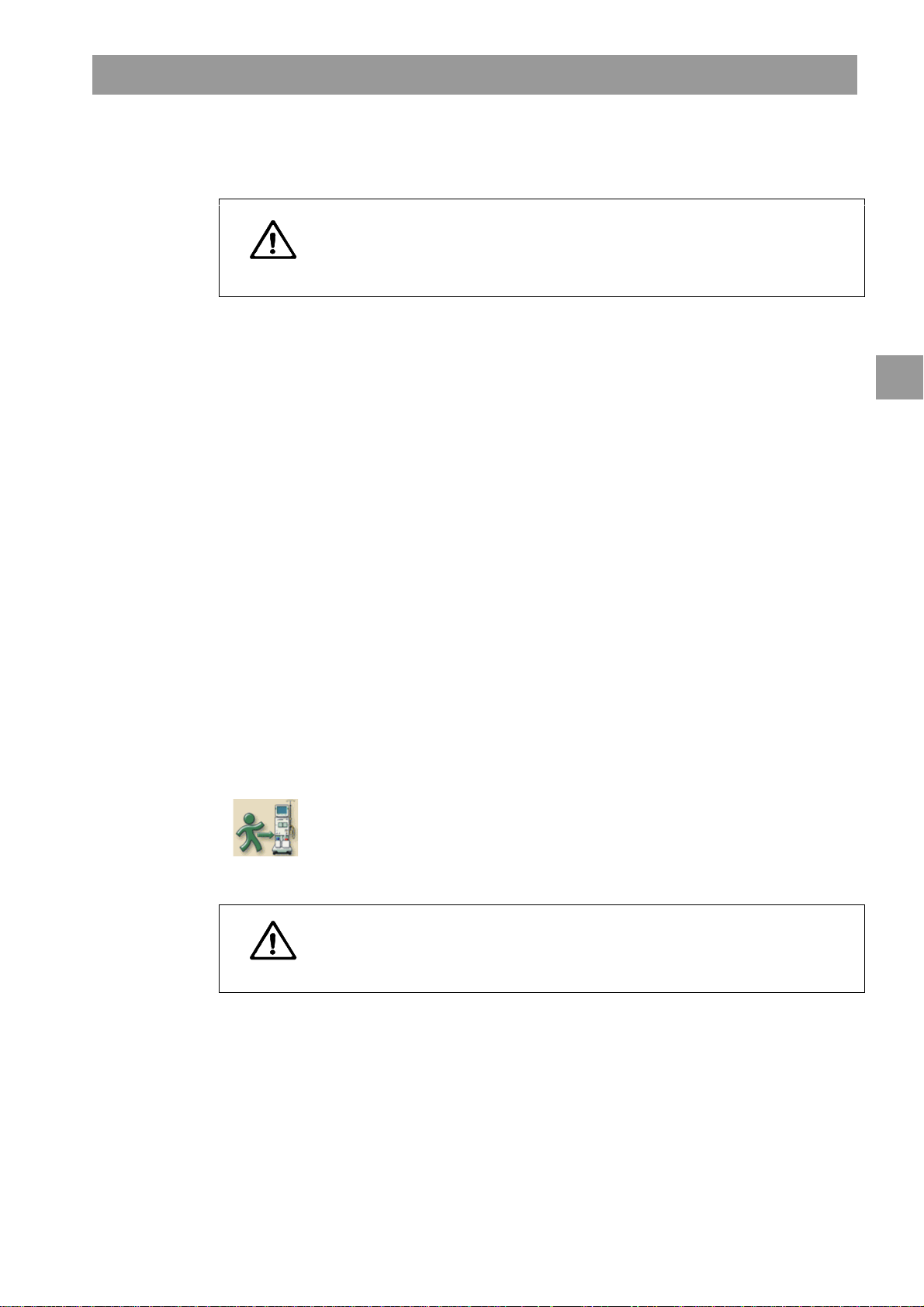
Dialog+® Preparing for hemodialysis
5.9 Rinsing the dialyzer
Intoxication risk for the patient in case of use of dialyzers packed with germicide.
Residual sterilant in the sodium priming bag!
WARNING
Verify the absence of sterilant in saline bag.
Replace saline bag before connecting the patient.
5.9.1 Rinsing the dialyzer using standard A/V tubing
When the dialysate is prepared, an information window appears, with the request to
connect the dialyzer.
Take dialyzer tubings from rinsing bridge and connect to dialyzer. Observe
color-coding.
Turn dialyzer so that the blue connection is facing downward.
Confirm correct connection of dialyzer by pressing the Enter key on the monitor.
The dialyzer is filled and rinsed.
Adjust level as follows:
– Fill chamber in front of the dialyzer entry (PBE) nearly half full.
– Fill venous drip chamber up to approx. 1 cm from the upper edge.
Once the dialyzer has been filled, the blood pump stops running. An information
window appears.
Ensure that the blood tubing system and the dialyzer are filled and rinsed with
physiological saline solution.
Ensure that the level in the venous chamber is correct.
Confirm correct settings by pressing Enter key on the monitor.
The dialysis machine is testing the blood tubing system.
This icon is enabled as soon as the dialysis machine has completed all automatic tests
and blood side tests.
Test the dialyzer and lines for a negative sterilant result.
The patient can now be connected.
5
WARNING
In the case of use of dialyzers packed with germicide, the rinse program should
be completed and the dialyzer tested for residual sterilant prior to changing to
the therapy phase.
IFU 38910363US / Rev. 2.15.10 / May 2016 5-33
Page 94
5
Preparing for hemodialysis Dialog+®
5.9.2 Rinsing the dialyzer using Streamline® bloodline
When the dialysate is prepared, an information window appears, with the request to
connect the dialyzer.
Take dialyzer tubings from rinsing bridge and connect to dialyzer. Observe
color-coding.
Confirm correct connection of dialyzer by pressing the Enter key on the monitor.
The dialyzer is filled and rinsed.
Adjust level as follows:
– Ensure that the venous drip chamber is completely primed.
Once the dialyzer has been filled, the blood pump stops running. An information
window appears.
Ensure that the blood tubing system and the dialyzer are filled and rinsed with
physiological saline solution.
Ensure that the level in the venous chamber is correct.
Confirm correct settings by pressing Enter key on the monitor.
The dialysis machine is testing the blood tubing system.
WARNING
This icon is enabled as soon as the dialysis machine has successfully completed all
automatic tests and the blood side tests.
Test the dialyzer and lines for a negative sterilant result.
Ensure that the blue connection is facing upwards.
The patient can now be connected.
In the case of use of dialyzers packed with germicide, the rinse program should
be completed and the dialyzer tested for residual sterilant prior to changing to
the therapy phase. Decalcify the machine after each bicarbonate dialysis if the
DF option is used.
5-34 IFU 38910363US / Rev. 2.15.10 / May 2016
Page 95
Dialog+® Preparing for hemodialysis
5.10 Stand-by mode
The dialysis machine features a stand-by mode for the dialysate side. This mode allows
switching off the dialysate side in order to save on permeate and concentrate when
the machine is being prepared and will not be used immediately.
Risk of microbial growth in the dialysate during stand-by mode!
Infection risk to the patient!
Do not use stand-by mode with dialyzers packed with germicide.
Do not run the dialysis machine in stand-by mode over prolonged periods.
WARNING
The recommended duration of stand-by mode depends on the water quality
and the environmental conditions (according to the hygiene plan of the
dialysis center).
5.10.1 Activating the stand-by mode
5
Depending on the service program setting performed by technical service, there are
the following ways in which the stand-by mode can be activated for an adjustable
period:
• Automatic start after automatic test sequence
• Automatic start after rinsing program
• Manual start after automatic test sequence
• Manual start after rinsing program
Manual activation of the stand-by mode
Touch icon.
The dialysis machine is in stand-by mode.
The pumps stop and no dialysate is produced in the machine.
5.10.2 Switching off the stand-by mode
The max. duration of the stand-by mode is preset in the service program by technical
service.
Depending on the setting entered by the technical service in the service program,
there are the following options for switching off the stand-by mode:
• Manual switch-off
• Automatic switch-off after expired time
• Automatic switch-off during connection of patient
Manual switch-off of stand-by mode (deactivating)
Touch icon again.
The pumps are started and dialysate is circulated without passing through the
dialyzer.
The machine is in bypass.
The machine will remain in bypass until the therapy is initiated.
IFU 38910363US / Rev. 2.15.10 / May 2016 5-35
Page 96

Preparing for hemodialysis Dialog+®
5.11 Power failure in preparation
During a power failure in preparation the status of this phase will be saved. If the
power supply will be restored, only the interrupted step must be repeated by the
device, if necessary.
Already entered treatment parameters will remain unchanged.
The saved data will be stored up to 120 minutes. After that time the device has to be
newly prepared.
5
This functionality allows for moving of a prepared device to another treatment area.
5.12 Changing the bicarbonate cartridge during preparation
It is possible to exchange a bic cartridge during preparation. (see chapter 10.2).
5-36 IFU 38910363US / Rev. 2.15.10 / May 2016
Page 97

Dialog
+
® Initiating hemodialysis
Table of contents
6 Initiating hemodialysis........................................................................ 6-3
6.1 Checking the patient data................................................................... 6-3
6.2 Connecting the patient and starting hemodialysis...........................6-4
6.2.1 Level regulation in therapy (if present)..............................................6-5
6.3 During hemodialysis............................................................................. 6-7
6.3.1 Monitoring the blood-side pressure limits........................................6-7
6.3.2 Treatment at minimum UF rate............................................................6-9
6.3.3 Heparin bolus..........................................................................................6-10
6.3.4 Arterial bolus (saline)............................................................................6-10
6.3.5 Graphic representation of treatment parameters (trend)..........6-12
6.3.6 Interrupting hemodialysis (bypass)...................................................6-15
6.3.7 Completion of treatment.....................................................................6-15
6.3.8 Terminating treatment .........................................................................6-15
6.3.9 Continuing treatment...........................................................................6-15
6
IFU 38910363US / Rev. 2.15.10 / May 2016 6-1
Page 98

6
Initiating hemodialysis Dialog
+
®
6-2 IFU 38910363US / Rev. 2.15.10 / May 2016
Page 99

Dialog
+
® Initiating hemodialysis
6 Initiating hemodialysis
6.1 Checking the patient data
After completion of the preparation work, the icon for connecting the patient is
enabled. The signal lamps on the monitor change to yellow.
Touch icon in preparation screen.
Two brief acoustic signals are sounded. The Enter key on the monitor is lit up. An
overview of the entered patient data appears on the screen.
Check that both sets of data match. If not, DO NOT USE THE MACHINE.
6
WARNING
Fig. 6-1 "Patient data" screen
Risk to the patient due to inadequate monitoring of treatment parameters!
If only one or no acoustic signal is sounded or Enter key flashes on the
monitor, or if the displayed treatment parameters show discrepancies, the dialysis
machine is defective and must not be used!
Leave screen by pressing CANCEL.
Call technical service.
Check that patient data corresponds with what has been prescribed by the doctor
and confirm by pressing the Enter key on the monitor.
The treatment screen appears and the dialysis machine is in the bypass mode.
IFU 38910363US / Rev. 2.15.10 / May 2016 6-3
Page 100

6
Initiating hemodialysis Dialog
6.2 Connecting the patient and starting hemodialysis
Risk to patients with central venous catheters, due to excessive patient leakage
current!
WARNING
Legend
Remaining time,
1
graphical and in numbers
UF rate
2
Actual UF volume
3
Set UF volume
4
Heparin rate
5
Blood flow
6
Heparin bolus
7
Min UF
8
Bypass
9
Information bar
10
Display of trans-membrane
11
pressure (TMP), with limits
Display of arterial pressure,
12
with limits
Display of venous pressure, with
13
limits
Connect electrical ground on the dialysis machine, see section 1.5.2.
+
®
Fig. 6-2 "Hemodialysis" treatment screen
During the connection phase, the set limit values are not monitored. Therefore,
particular care is required during the connection phase.
The following steps for connecting the patient may be slightly different depending on
clinics policy.
Connect patient arterially.
Start blood pump by pressing START/STOP button on monitor.
Set blood flow.
Fill blood tubing system with blood.
6-4 IFU 38910363US / Rev. 2.15.10 / May 2016
 Loading...