

Page 1
g
+
Dialo
SW 9.xx
Service Manual
English
Edition 1 -2010
M.KAY Dialog+ SW9xx SM EN 1-2010
Page 2
Dialog
+
SW 9.xx
Service Manual 1/2010
I
Contact your Local
B. Braun Representative
for Service Support
B. Braun Avitum AG
BA-TE-DE08C M.KAY -
34209 Melsungen
Germany
Tel. No.: +49 5661 713500 (Günter Ni ssen)
E-Mail: guenter.nissen@bbra un.com
Dialog+ SW9xx_sm_TOC_1-2010.doc/pdf <100329> yymmdd
B. Braun Avitum AG
Page 3

Dialog
+
SW 9.xx
Service Manual 1/2010
Valid for the following machine type:
For Software ≥ 9.xx
Dialog+: from serial no. 100000
Dialog+ HDF-Online: from serial no. 150000
II
BA-TE-DE08C M.KAY -
Registration Number:
Service Manuals with a registr ation nu mber a re inclu ded in the upda te serv ice!
Dialog+ SW9xx_sm_TOC_1-2010.doc/pdf <100329> yymmdd
B. Braun Avitum AG
Page 4

+
Dialog
Prevent Electrical Shock H azard
SW 9.xx
Commissioning and Service Only trained personnel must service the Dialog+, i.e. repair, maintenance, software
!
Protective Conductor in TFT Housing
TSM Service Progr am
Prevent Chemical Burns and Scalding During servicing on running machines: prevent chemical burns and scalding of the skin
Contaminated Machines Protective gear should be worn in case of servicing of assumed contaminated
Disposal and Taking Back
System Configuration The system configuration saved on a diskette must be downloaded to an other Dialog+
Service Manual 1/2010
Copyright This document is the pr operty of B. Braun Avitu m AG with all rights reserved.
installation, firmware update, r etrofitting and commissioning of th e Dialog+.
Servicing must only be performed with proper tools, calibration equipment and be in
accordance with the most recent revision of this service manual/technical information,
which must be clearly and thoroughly understood.
Switch off the Dialog+ and disconnect unit from mains if you have to open the
machine for servicing. Do not touch any exposed wiring or conductive surfaces while
the Dialog+ is opened. The voltages present when electrical power is connected to the
Dialog+ can ca use serious injury or death.
ESD Information Pay attention to ESD information, because electronic components are sensitive to
electrostatic discharges.
High Voltage
in TFT Monitor
Software
Therapy Mode
Calibration
Tubing
Wiring
Cover in Rear Door Servicing of mechanical assembly groups (components in contact with fluid): the cover
O-Rings Always check o-rings from disassembled groups/components and replace if necessary.
Figures The displayed figures can differ slightly from the machines on site, due to different
Fuses If fuses are replaced they must exactly match the type and rating specified by the
Spare Parts Only use original spare parts manufactured and sold by B. Braun Avitum AG.
of Spare Parts
Function Check Check the respective function of the assembly group/component after servicing. A
If a battery option is present in the machine:
High voltage can be present at the backlight inverter board BIB in the TFT monitor,
even if the machine has been disconnected from mains. Pull out the battery
compartment in the base platform and switch off the battery voltage before opening
the machine.
If the TFT housing had to be opened during a service job, the tight seat of the
protective conductors in the TFT housing must be checked.
Only activate the TSM service program for service activities. It is prohibited to connect
a patient to the Dialog+ and to run a therapy if the TSM service program is activated
in the Dialog+. If the TSM service program is activated the complete alarm system is
disabled. The TSM service program is started in the service mode: digital board, service
switch S1, position 2.
The software is installed in the software mode: digital board, service switch S1,
position 3.
After completion of all procedures switch back to the therapy mode: digital board,
service switch S1, position 0.
Only perform a calibration after the Dialog+ has reached working temperature and the
machine was disinfected and decalcified. Save the calibration data (CFC) before you
exit the TSM service program:
Tubing must be replaced only by the same tubing type/length and identical installation
manner.
Make sure that the tubings in the machine are not kinked or twisted after servicing
(e.g. if sub-racks are pulled out and inserted again). The tubing must not touch
moving/rotating co mponents (e.g. motors of gear pumps).
Wiring must be replaced only by the same cable type/length and identical installation
manner. The cables must not touch moving/rotating components (e.g. motors of gear
pumps).
due to the penetration of disinfectant or hot liquid.
machines.
for the switch mode power supply microcontroller SMPS-MC in the rear door must be
assembled during servicing because it serves as a spray protection.
hardware statuses.
manufacturer in the spare parts list/technical information. Where applicable: fuses
must be approved by UL/CSA.
Dispose spare parts (e.g. boards or batteries) according to local disposal guidelines or
send back to B. Braun Avitum AG free of charge (see chapter 7).
machine only if:
•
the hardware matches and
•
the identical software version number is present.
complete function check must be performed after every service, according to the
operating manual.
TSM Main Menu, File Operations, Save Calibration Data
III
.
BA-TE-DE08C M.KAY -
Dialog+ SW9xx_sm_TOC_1-2010.doc/pdf <100329> yymmdd
B. Braun Avitum AG
Page 5

Dialog
+
SW 9.xx
Service Manual 1/2010
Table of C ont e nt s Pa ge
IV
1. Installation and Commissioning
2. Technical System Description
3. Repair Instructions
4. TSM Service Program
5. Technical Safety Inspection with Preventive Maintenance
6. Flow, Wiring and Tubing Diagrams
7. Spare Parts List
8. Appendix
8.1 ESD/EMC Information
8.1.1 Electrostatic Discharge ESD
8.1.2 Electromagnetic Compatibility EMC
1-1
2-1
3-1
4-1
5-1
6-1
7-1
8-1
8-2
8-2
8-4
8.2 Technical Information
8.3 Assembly Instructions
8.4 Field Service Information
8.5 Instruction Leaflets
9. Edition/Updates Service Manual
-
-
-
-
9-1
BA-TE-DE08C M.KAY -
Dialog+ SW9xx_sm_TOC_1-2010.doc/pdf <100329> yymmdd
B. Braun Avitum AG
Page 6
V
Dialog
Conventions
+
SW 9.xx
Service Manual 1/2010
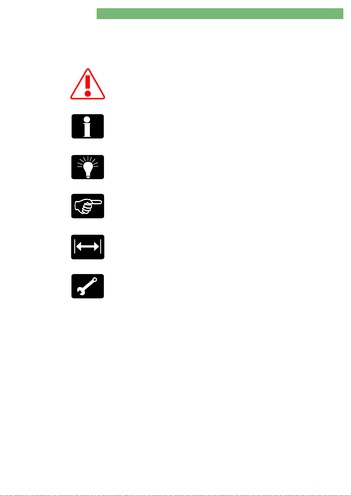
Symbol Description
Attention
The symbol gives information, which are safety relevant for
the Dialog+ and must be observed.
Information
The symbol gives additional information, which should be
observed.
Tips
The symbol gives additional hints, which can be helpful.
Handling
The symbol gives information for a handling at or in the
machine, i.e. during a calibration, disassembly or assembly.
Calibration
The symbol appears for necessary calibration measures.
Calibration Equip m ent / Tools
The symbol gives remarks for necessary calibration
equipment/tools, i.e. during a calibration, disassembly or
assembly.
BA-TE-DE08C M.KAY -
Dialog+ SW9xx_sm_TOC_1-2010.doc/pdf <100329> yymmdd
B. Braun Avitum AG
Page 7

V
Dialog
+
SW 9.xx
Service Manual 1/2010
I
Service Manual
Service Training
The edition of this service manual is for the maintenance and repair of the
Dialog+ machine with a software ≥ 9.01. The service manual is subject to
amendments.
A service training is essential to meet the B. Braun standard operating
procedures for qualified service and support.
The user of this documentation should only use this documentation in
combination with a participation in a B. Braun service training.
The user of this documentation should h ave the following qualifications and
prerequisites:
1. Mechanics, digital/analogue techniques, optoelectronics, measurement and
PC techniques.
2. Participation in a B. Braun service training to accomplish qualified
maintenance, repair and service support.
3. Availability of approved and calibrated test equipment and tools given in
this service manual.
Contact your local B. Braun representative or dealer for detailed inform ation
concerning training courses.
B. Braun Avitum AG
34209 Melsungen, Germa ny
Tel.: +49 5661 712718
Fax.: +49 5661 752718
E-Mail: marina.ritz-nickel@bbraun.com
Technical Safety Inspection
Instructions for Use
ESD/EMC Information
Spare Parts
Perform regular technical safety inspections as described in chapter 5 of this
service manual to ensure the safety of the machine.
An instructions for use can be ordered at your local B. Braun representative or
dealer.
Please observe the ESD/EMC information (see appendix for additional
information):
• ESD: electrostatic discharge
• EMC: electromagnetic compatibility
Only original spare parts manufactured and sold by B. Braun are applicable.
Please provide part number and description respectively when ordering any
spare parts. Please order your spare parts at your local B. Braun representative
or dealer.
B. Braun Avitum AG
34209 Melsungen, Germa ny
Tel. No.: +49 5661 713662
E-Mail: heike.sinning@bbraun.com
dialysetechnik.melsungen@bbraun.com
The main assembly groups are defined according to the spare parts list. The
main assembly groups are especially:
• All pcb's (printed circuit boards)
• Pumps
• DF block
• Ultrafiltration
• Blood leak detector
• Safety air detector
• Heater
Tamper or repairs in these assembly groups are not permissible (due to
calibration, ESD, multi-layer pcb's and the application of SMT (SMT = surface
mounted technology).
Calibration Serv ice
BA-TE-DE08C M.KAY -
Dialog+ SW9xx_sm_TOC_1-2010.doc/pdf <100329> yymmdd
All calibration devices must be approved and registered with an identification
number. The calibration equipment is subjec t to the B. Braun calibration service
and must be checked and recalibrated in regular intervals, to meet th e B. Braun
standard operating procedures SOPs. Only approved and registered calibration
equipment must be applied for servicing.
B. Braun Avitum AG
Page 8

1. Commissioning 1/2010 1 - 1
Dialog
Copyright
Commissioning and Service
Prevent Electrical Shock Hazard
ESD Information
High Voltage
in TFT Monitor
Protective Conductor in TFT Housing
TSM Service Program
Software
Therapy Mode
Calibration
Prevent Chemical Burns and Scalding
Contaminated Machines
Cover in Rear Door
Tubing
Wiring
Fuses
Spare Parts
Instructions for Use
Check Machine
Commissioning
Electrical Installation
Mains Voltage Supply
Ambient Temperature
Water Installation
Water Quality
Central Hot Cleaning System
+
SW 9.xx
This document is the property of B. Braun Avitum AG with all rights reserved.
Only trained personnel must service the Dialog+, i.e. repair, maintenance, software installation, firmware
update, retrofitting and commissioning of the Dialog+.
Servicing must only be performed with proper tools, calibration equipment and be in accordance with the
most recent revision of this service manual/technical information, which must be clearly and thoroughly
understood.
Switch off the Dialog+ and disconnect unit from mains if you have to open the machine for servicing.
Do not touch any exposed wiring or conductive surfaces while the Dialog+ is opened. The voltages present
when electrical power is connected to the Dialog+ can cause serious injury or death.
Pay attention to ESD information, because electronic components are sensitive to electrostatic discharges.
If a battery option is present in the machine:
High voltage can be present at the backlight inverter board BIB in the TFT monitor, even if the machine has
!
been disconnected from mains. Pull out the battery compartment in the base platform and switch off the
battery voltage (remove fuse) before opening the machine.
If the TFT housing had to be opened during a service job, the tight seat of the protective conductors in the
TFT housing must be checked.
Only activate the TSM service program for service activities. It is prohibited to connect a patient to the
Dialog+ and to run a therapy if the TSM service program is activated in the Dialog+. If the TSM service
program is activated the complete alarm system is disabled. The TSM service program is started in the service
mode: digital board, service switch S1, position 2.
The software is installed in the software mode: digital board, service switch S1, position 3.
After completion of all procedures switch back to the therapy mode: digital board, service switch S1,
position 0.
Only perform a calibration after the Dialog+ has reached working temperature, and the machine was
disinfected and decalcified. You should save the calibration data to the hard disk drive before you exit the
TSM service program:
During servicing on running machines: prevent chemical burns and scalding of the skin due to the
penetration of disinfectant or hot liquid.
Protective gear should be worn in case of servicing of assumed contaminated machines.
Servicing of mechanical assembly groups (components in contact with fluid): the cover in the rear door must
be assembled during servicing because it serves as a spray protection for the SMPS-MC.
Tubing must be replaced only by the same tubing type/length and identical installation manner.
Make sure that the tubings in the machine are not kinked or twisted after servicing (e.g. if sub-racks are
pulled out and inserted again). The tubing must not touch moving/rotating components (e.g. motors of gear
pumps).
Wiring must be replaced only by the same cable type/length and identical installation manner. The cables
must not touch moving/rotating components (e.g. motors of gear pumps).
If fuses are replaced they must exactly match the type and rating specified by the manufacturer in the spare
parts list/technical information. Where applicable: fuses must be approved by UL/CSA.
Only use original spare parts manufactured and sold by B. Braun Avitum AG.
Please pay attention to the information in the instructions for use
Check completeness of machine and transport damages after unpacking.
Do not start machine if a safe operation is not guaranteed.
The electrical installation must correspond with national regulations for initial operation of the unit (e.g. IEC
publications). The machine must not be operated in hazardous locations or rooms. The potential equalisation
must be in accordance with national requirements (e.g. IEC publications)
The mains voltage supply must correspond with the mains voltage on the unit type plate!
Before the Dialog+ is switched on the machine must have room temperature (see instructions for use,
chapter 15).
The installation must be in accordance with national regulations e.g. DVGW work sheet W503 for
haemodialysis equipment and VDE 0753 (rules of application for haemodialysis equipment).
A pipe disconnector is not necessary if a water softener or water softener with built-in reverse osmosis
system is installed. A nonreturn valve and a bleed pipe are adequate. Please see DVGW work sheet W 503,
section 4.4 and VDE 0753 part 4 (Rules of application for haemodialysis equipment).
Only water of the highest quality should be applied. Please consider the following, especially for bicarbonate
dialysis:
• Inlet water shall be free of Mg
If the machine is connected to a central hot cleaning system a high temperature tubing must be used for the
water inlet.
TSM Main Menu, File Operations, Save Calibration Data
++
and Ca++.
.
BA-TE-DE08C M.KAY Dialog+ SW9xx_SM_Chapter 1-1_1-2010.doc/pdf <110301> yymmdd B. Braun Avitum AG
Page 9
1. Commissioning 1/2010 1 - 2
1
Dialog
+
SW 9.xx
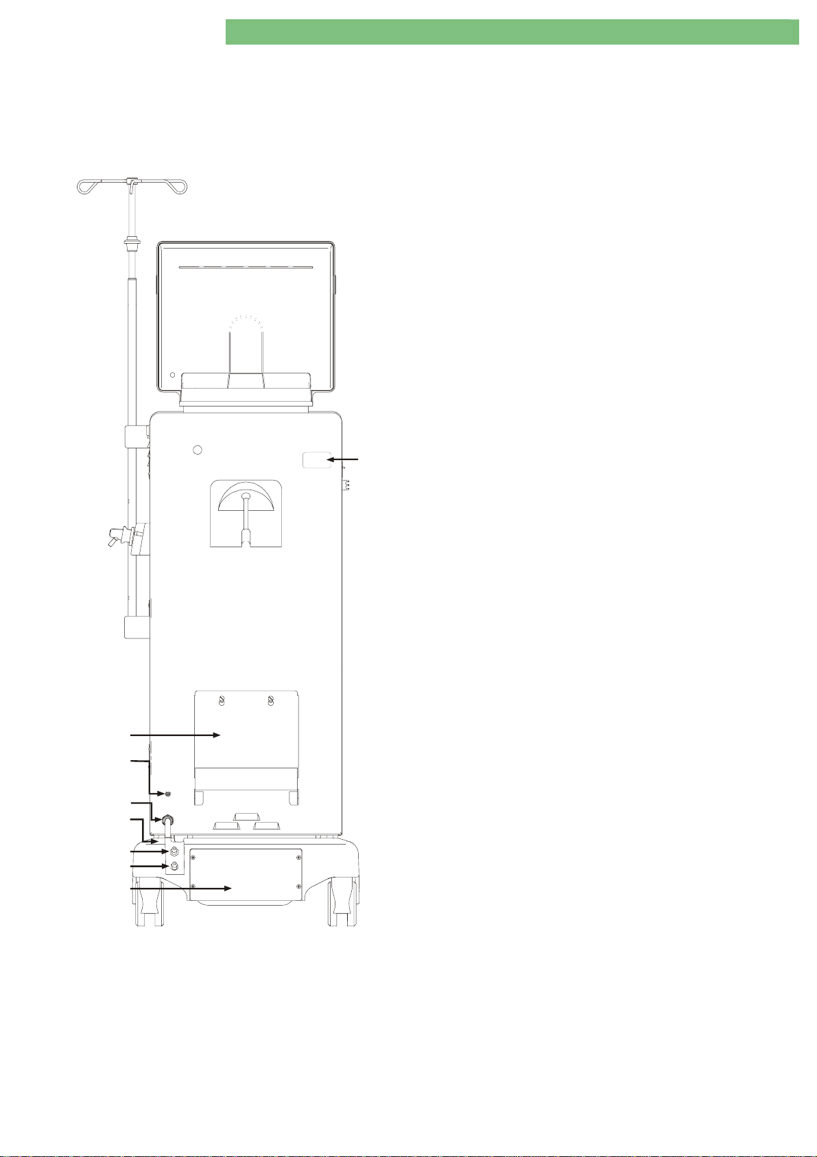
Legend
1. Type Plate
2. Canister Holder
3. Potential Equalisation Bolt
4. Main Cord
2
3
4
5
5. Central Concentrate Supply Option
6. Tubing Connection Water Inlet
• PVC tubing 10 x 3 mm (red)
(fasten with two single ear clamps 19.5)
• Tubing length: approx. 3 m
6.1 Tubing Connection Water Inlet for Osmosis Device
with Hot Disinfection of the Loop Line
• Silicone tubing 8 x 3.2 mm (high temperature tubing, red)
(fasten with two single ear clamps 19.5)
7. Tubing Connection Dialysate Outlet
• PVC tubing 10 x 3 mm (black)
(fasten with a single ear clamp 19.5 and a tubing clamp 1220 mm)
• Tubing length: approx. 3 m
• Drain height: max. 80 cm
8. Emergency Power Supply/Battery Option
6
7
8
Fig.: Dialog+ Rear View
BA-TE-DE08C M.KAY Dialog+ SW9xx_SM_Chapter 1-1_1-2010.doc/pdf <110301> yymmdd B. Braun Avitum AG
Page 10

1. Commissioning 1/2010 1 - 3
Dialog
+
SW 9.xx
Table of Contents Page
1.1 Commissioning Check List
1.1.1 Measurement Circuits for the Measurement of the Electrical
Safety According to EN 62353/60601-1
1-4
1-6
BA-TE-DE08C M.KAY Dialog+ SW9xx_SM_Chapter 1-1_1-2010.doc/pdf <110301> yymmdd B. Braun Avitum AG
Page 11
1. Commissioning 1/2010 1 - 4
Dialog
+
SW 9.xx
1.1 Commissioning Check List
For Dialog+ SW 9.xx
REF {Type/Typ}:................................................. SN {Serien-No./Nr.}: ................................................
Year of Purchase: ....................... Responsible Organisation (User): .....................................................
.........................................................................................................................................................................
Operating Hours: .................................... h Inventory No.: ..................................................................
SW Version: ...........................................
The commissioning (putting into service) shall be performed and documented before the machine
is handed over to the responsible organisation (user), according to the specified check list, with
reference to the service manual and instructions for use.
Manufacturer:
B. Braun Avitum AG
34209 Melsungen, Germany
Check List
Note: Text in { } brackets is information for the execution of the check list!
1. Visual Inspection
1.1 {Machine: clean/complete; no damages/moisture influences or loose assemblies; no moveable parts touching tubings or wires; casters are moveable;
type plate legible}
1.2 {Check tight seat and damages of mains supply (power supply cord, strain relief), potential equalisation cable, staff call/data lines (if present) and
connectors}
2. Protective Earth Resistance According to EN 62353
2.1 Protective Earth Resistance:
< 0.3 [Ω] {note highest value}: ................................................ [Ω]
{(Machine in cl. power supply cord. Move the power supply cord during the check. Thus possible loose connections can be detected. Data lines and
potential equalisation cable must not be connected during the check of the of the protective earth resistance (see figure 1)}
{Measurement points:}
{Exterior: Potential equalisation bolt, rinsing bridge (dialyser inlet and outlet)}
{Interior: Heater body (top), rear door (top left corner), frame (rear), housing cover (top left), front door (top left)}
{Monitor: Monitor (one of the screws in the front panel/housing}
3. Install Machine
3.1 {Connect water inlet to the metal tubing connector and fasten with single ear clamp.
Connect dialysate outlet to plastic tubing connector and fasten with tubing clamp.}
3.2 {Connect central supply for concentrate (central supply option) and deaerate tubings}
3.3 {Assemble holder for disinfectant (if option present)}
3.4 {Assemble dialyser holder}
3.5 {Assemble filter holder. Insert DF filter (option)}
3.6 {Assemble DF filter/HDF filter (if option present)}
OK
4. Function Inspection
{Pay attention to the filling procedure of the machine to prevent dry run of the heater!}
4.1 Switch on machine, fill and rinse: - {Switch machine in Test 1.10 Degassing and Heating menu and fill with water until
water flows out of the dialysate outlet. Then rinse in disinfection (approx. 5 minutes).}
4.2 Automatic Blood Pressure Measurement ABPM
4.2.1 ABPM Option: - Measurement on a test person is plausible
4.3 Customer Specific System Setting: - {Switch machine in TSM Service Program: Execute Treatment Support (calibrate PE offset for
altitudes > 1000 m}
Option present no yes
BA-TE-DE08C M.KAY Dialog+ SW9xx_SM_Chapter 1-1_1-2010.doc/pdf <110301> yymmdd B. Braun Avitum AG
Page 12
1. Commissioning 1/2010 1 - 5
Dialog
Check List
+
SW 9.xx
OK
Note: Text in { } brackets is information for the execution of the check list! SN {Serien-No./Nr.}............................................
5. Setting into Service According to Instructions for Use with Electrical Safety Check According to
EN 62353/EN 60601-1
5.1 Applied Accessories/Disposables:
- Applied line system:
Name: ......................................................................................................................................................................................
5.2 Switch on machine: - Self-test passed {and 15 minutes therapy with UF safety check}
- Ultrafiltration comparison measurement 15 minutes with UF rate 500 ml/h: ......................... [ml]
(125 ml UF volume ±15 ml)
5.3 Temperature: - Comparison measurement {at dialyser coupling}, at 37 oC (-1.5; +0.5): ......................... [oC]
5.4 Conductivity: - Comparison measurement {at dialyser coupling}, e.g. 14.3 mS/cm (±0.2): ................. [mS/cm]
5.5 Equipment Leakage Current:
{All water connections and data lines must be connected during the check of the equipment leakage current (see figure 2)}
≤ 0.5 [mA] - During heat-up phase {change mains polarity and note highest value}: ....................... [mA]
5.6 Patient Leakage Current:
{All water connections and data lines must be connected during the check of the patient leakage current (see figure 3)}
< 10 [µA] AC - Under normal conditions {at dialyser coupling}, conductivity at 13 – 15 mS/cm: ........................ [µA]
5.7 Safety Air Detector (SAD): - Test alarm function (visual/audible) passed
5.8 Disinfection: - Start
Applied Measurement Equipment:
Electrical Safety: ........................................................................................ * ID/Serial No.: .................................
Conductivity: ............................................................................................... * ID/Serial No.: .................................
Temperature: ............................................................................................... * ID/Serial No.: .................................
Pressure: ....................................................................................................... * ID/Serial No.: .................................
Balance: ........................................................................................................ * ID/Serial No.: .................................
Pressure Manometer: ............................................................................... * ID/Serial No.: .................................
Other Measurement Device: ................................................................... * ID/Serial No.: .................................
......................................................................................................................... * ID/Serial No.: .................................
* If applicable, please enter the type and identification number of the equipment used.
Comments:
..........................................................................................................................................................................................................................................................
..........................................................................................................................................................................................................................................................
..........................................................................................................................................................................................................................................................
Next Inspection Date:
The commissioning was performed and the
machine was hand over to the responsible
organisation (user).
............................................................................................................................................................
Name Service Technician: Name of Company:
...................................................................................
................................................................................... .................................................................
Date/Signature
BA-TE-DE08C M.KAY Dialog+ SW9xx_SM_Chapter 1-1_1-2010.doc/pdf <110301> yymmdd B. Braun Avitum AG
Page 13
1. Commissioning 1/2010 1 - 6
A
A
A
Dialog
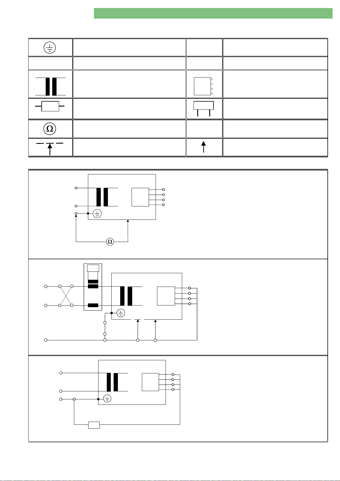
1.1.1 Measurement Circuits for Measurement of Electrical Safety
+
SW 9.xx
According to IEC 62353/60601-1
Protective earth (ground)
L, N
MP
Supply mains terminals
Mains part
MD
Measuring device
Resistance measurement equipment
Part of enclosure not protectively earthed
Table 1: Legend of Abbreviations and Symbols
L
N
PE
MP
AP
PE
P
Protective earth terminal
Applied part
M
Residual current meter with frequency
response as MD
Connection to accessible conductive parts
Protective Earth Resistance
Test current: ≥ 200 mA
The test current must be measured in both
directions.
Fig. 1: Protective Earth Resistance
L(N)
L
N
N(L)
PE
Fig. 2: Equipment Leakage Current
L
N
PE
M
MP
MP
Equipment Leakage Current:
P
• Differential Measurement
Patient Leakage Current
P
MD
Fig. 3: Patient Leakage Current
BA-TE-DE08C M.KAY Dialog+ SW9xx_SM_Chapter 1-1_1-2010.doc/pdf <110301> yymmdd B. Braun Avitum AG
Page 14

Dialog
+
SW 9.xx
2. Technical System Description 1/2010 2 - 1
Table of Content s Page
General Information 2-4
2.1 Overview Sub-Racks 2-5
2.1.1 Legend Overview Sub-Racks 2-5
2.2 Top Level Sub-Rack 2-6
2.2.1 Legend Top Level Sub-Rack 2-6
2.3 Basic Board BB 2-7
2.3.1 Legend Basic Board 2-7
2.4 Power Board Valves PBV 2-8
2.4.1 Legend Power Board Valves 2-8
2.5 Power Board Motors PBM 2-9
2.5.1 Legend Power Board Motors 2-9
2.6 Digital Board DB 2-10
2.6.1 Legend Digital Board 2-10
2.7 Analog Board AB 2-11
2.7.1 Legend Analog Board 2-11
2.8 HDF Online Board HOB 2-12
2.8.1 Legend HDF Online Board 2-12
2.9 UF Sub-Rack 2-13
2.9.1 Legend UF Sub-Rack 2-13
2.10 UF Sub-Rack HDF Online 2-14
2.10.1 Legend UF Sub-Rack HDF Online 2-14
2.11 DF Sub-Rack 2-15
2.11.1 Legend DF Sub-Rack 2-15
2.12 Water Sub-Rack 2-16
2.12.1 Legend Water Sub-Rack 2-16
2.13 Rinsing Bridge 2-17
BA-TE-DE08C M.KAY
2.13.1 Legend Rinsing Bridge 2-17
2.14 Rear Door 2-18
2.14.1 Legend Rear Door 2-18
2.15 Switch Mode Power Supply Microcontroller SMPS-MC 2-19
2.15.1 Legend Switch Mode Power Supply Microcontroller 2-19
2.16 TFT Monitor 2-20
2.16.1 Legend TFT Monitor 2-20
2.17 Front Door 2-21
2.17.1 Legend Front Door 2-21
Dialog+ SW 9xx_sm_C ha pter 2_1-2010.doc/pdf < 100329> yymmdd
B. Braun Avitum AG
Page 15

Dialog
+
SW 9.xx
2. Technical System Description 1/2010 2 - 2
2.18 Level Regulation Module 2-22
2.18.1 Legend Level Regulation Module 2-22
2.18.2 Flow Diagram Level Regulation Module 2-23
2.19 Flow Diagrams 2-24
2.19.1 Dialog+ 2-24
2.19.2 Dialog+ with BIC Option and DF Filter Option 2-25
2.19.3 Dialog+ HDF Online 2-26
2.19.4 Legend Flow Diagram 2-27
2.20 Description Flow Diagram 2-29
2.20.1 Water Inlet Section with Water Block 2-29
2.20.2 Degassing Circuit with Temperature System 2-30
2.20.3 Dialysate Processing 2-31
2.20.4 Central Bicarbonate and Concentrate Supply (Option) 2-32
2.20.5 BIC Cartridge Holder (Option) 2-32
2.20.6 Balance Chamber System 2-33
2.20.7 Working Principle Balance Chamber System 2-33
2.20.8 Ultrafiltration and Rinsing Bridge 2-35
2.20.9 Chemical Thermal Disinfection Program 2-36
2.21 Block Diagram 2-38
2.21.1 Legend Block Diagram 2-39
2.22 Switch Mode Power Supply Microcontroller SMPS-MC 2-42
2.22.1 Block Diagram SMPS-MC 2-42
2.22.2 System Integration SMPS-MC 2-43
2.22.3 Component Layout SMPS-MC 2-44
2.22.4 Wiring Diagram SMPS-MC with Battery Option 2-45
2.22.5 Description SMPS-MC 2-46
2.22.6 Fuses 2-48
2.22.7 Signals 2-49
BA-TE-DE08C M.KAY
2.22.8 Internal Signals 2-49
Dialog+ SW 9xx_sm_C ha pter 2_1-2010.doc/pdf < 100329> yymmdd
B. Braun Avitum AG
Page 16

+
Dialog
SW 9.xx
General Information
2. Technical System Description 1/2010 2 - 4
Operation is accomplished via a touch screen (TFT monitor). Two
microprocessor systems c ontr o l a nd mo ni tor the machine.
The hardware concept consists of the following systems:
Top Level System
•
Low Level System
•
The top level system consists of the following components:
Top Level Syst em
Communication module
•
Top level controller TLC (motherboard)
•
Compact flash card CFC
•
Options
•
The communication between the user and the machine is performed via the
top level.
Example data excha nge to c o mmuni c ation module:
Entry via input mask of the touch screen or keyboard
•
Output via the output mask of the TF T mo ni tor
•
Example data exchange to low level:
Transmitting and receiving data from/to low level controller and supervisor
•
on the digital board DB (LLD)
Low Level Syst em
The low level system consists of the following components:
Digital board DB (LLD)
•
Analog board AB (LLA)
•
Power board motors PBM
•
Power board valves PBV
•
The low level controls and monitors all functions.
Data exchange to top level c o ntr ol l er ( mother b oard):
Transmitting and receiving data from/to low level supervisor
•
Transmitting and receiving data from/to low level controller
•
Data exchange between low level controller to supervisor:
Transmitting and receiving messages, data and commands
•
All sensor data are sent separately, v ia two serial bus systems, to the supervisor
and controller via the analog board to the digital board. The actuators, motors
and valves are driven via the power board valves PBV and power board motors
PBM.
BA-TE-DE08C M.KAY
Dialog+ SW 9xx_sm_C ha pter 2_1-2010.doc/pdf < 100329> yymmdd
B. Braun Avitum AG
Page 17

Dialog
+
SW 9.xx
2. Technical System Description 1/2010 2 - 3
For Software
For Software
For Software For Software
9.xx
9.xx
≥≥≥≥
9.xx 9.xx
BA-TE-DE08C M.KAY
Dialog+ SW 9xx_sm_C ha pter 2_1-2010.doc/pdf < 100329> yymmdd
B. Braun Avitum AG
Page 18
Dialog
+
SW 9.xx
2. Technical System Description 1/2010 2 - 5
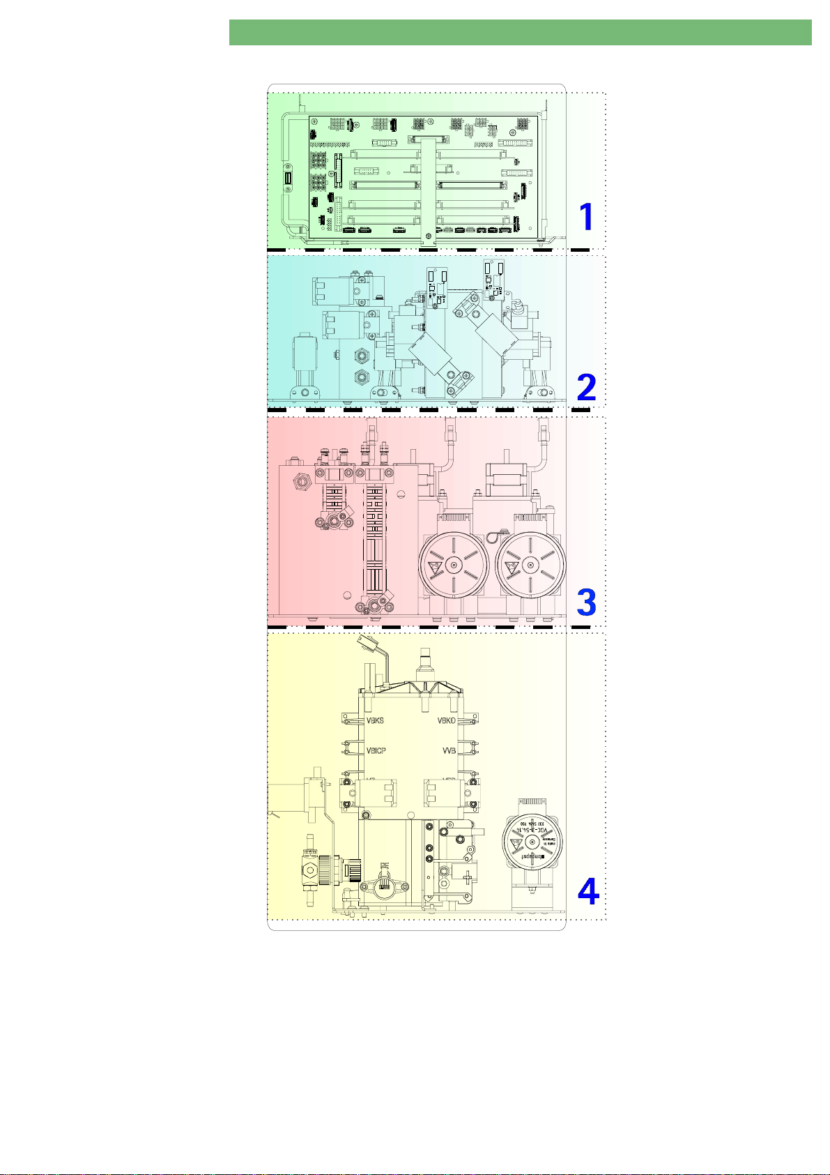
2.1 Overview Sub-Racks
4
11144
Fig. : Overview Sub-Racks Rear View Dialog+
2.1.1 Legend Ov erv iew Sub-Racks
BA-TE-DE08C M.KAY
Top Level Sub-Rack
1
UF Sub-Rack
2
Dialog+ SW 9xx_sm_C ha pter 2_1-2010.doc/pdf < 100329> yymmdd
DF Sub-Rack
3
Water Sub-Rack
4
B. Braun Avitum AG
Page 19
+
Dialog
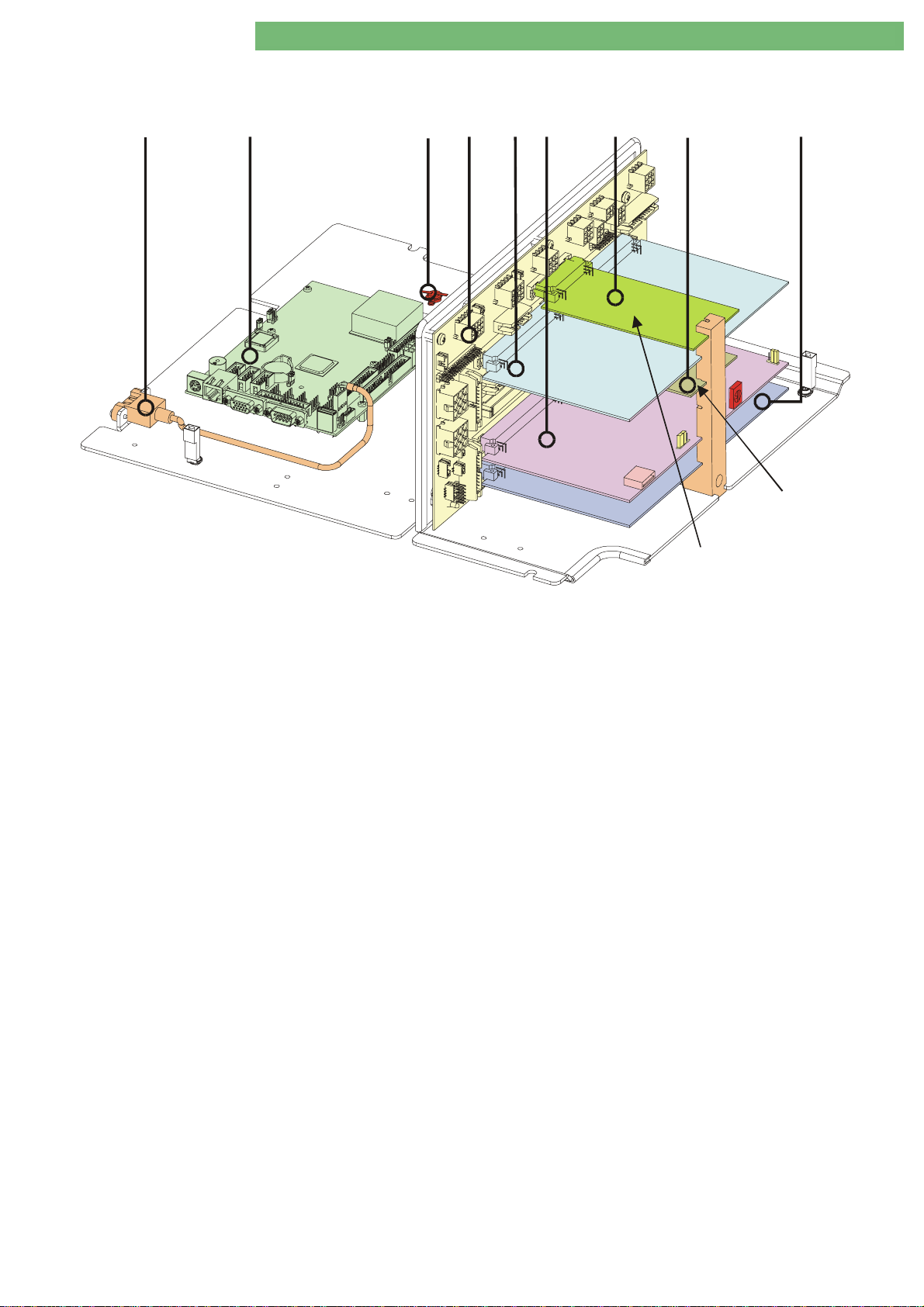
2.2 Top Level Sub-Rack
SW 9.xx
2. Technical System Description 1/2010 2 - 6
1
USB:
Service
SW
Fig. : Top Level Sub-Rack
2
Motherboard
4
3
Basic Board
5
6
Power Board
Valves
Digital Board
USB:
Analog Board
7
SW
89
JP2
S1
JP1
Power Board Motors
HDF BoardOnline
2.2.1 Legend To p Level Sub-Rack
1111 USB Port:
Service (FSU)/Software Installation TLC
2222 LX800 Motherboard
3333 Temperature Switch TS (closes at 50 ± 3
4444 Basis Board BB
5555 Power Board Valves PBV
6666 Digital Board DB (LLD):
USB Port: Software Installation LLC/LLS; Service-Switch S1; Jumper JP1/JP2
7777 HDF Online Board HOB
8888 Power Board Motor PBM
9999 Analog Board AB (LLA)
o
C, opens at 35 ± 6 oC)
BA-TE-DE08C M.KAY
Dialog+ SW 9xx_sm_C ha pter 2_1-2010.doc/pdf < 100329> yymmdd
B. Braun Avitum AG
Page 20

+
Dialog
SW 9.xx
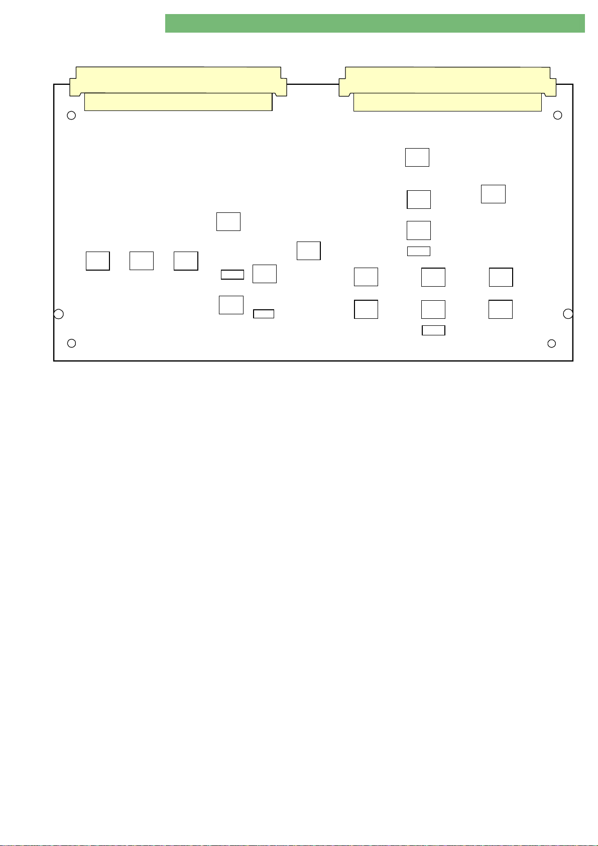
2.3 Basic Board BB
2. Technical System Description 1/2010 2 - 7
P3
P48
P26
P17
P54
P58
P31
P10
P49
P51
P32
1
P24
P6
1
1
1
P50
Fig. : Basic Board
2.3.1 Legend Basic Board
P1
P1 Degassing Pump EP
P1P1
P2
P2 Venous Blood Pump BPV
P2P2
P3
P3 Arterial Blood Pump BPA
P3P3
P4
P4 Outlet Flow Pump FPA
P4P4
P5
P5 Safety Air Detector SAD
P5P5
P6
P6 Heparin Pump HP (HEP)
P6P6
P7
P7 Air Separator Level Sensor LAFS
P7P7
P8
P8 BIC Pump BICP
P8P8
P9
P9 Concentrate Pump KP
P9P9
P10
P10 All Valves (+ Option BIC) VALVES
P10P10
P11
P11 Level Regulation LR
P11P11
P12
P12 DIABUS
P12P12
P13
P13 HDF Online Board HOB
P13P13
P14
P14 Front Panel Board FPB
P14P14
P15
P15 Valves Balance Chamber VCH
P15P15
P16
P16 UF Pump UFP
P16P16
P17
P17 Power Supply 1 PS1
P17P17
P18
P18 Not Applicable
P18P18
P19
P19 Not Applicable
P19P19
P20
P20 Inlet Flow Pump FPE
P20P20
P21/P22
P21/P22 Power Board Valves PBV
P21/P22P21/P22
P23
P23 Staff Call PERS-R
P23P23
P24
P24 Control SMPS-MS (NT)
P24P24
P25
P25 Power Board Motors PBM
P25P25
P26
P26 Disinfection Valve VD
P26P26
DIABUS
DIABUSDIABUS
SMPS-MS (NT)
SMPS-MS (NT)SMPS-MS (NT)
P59
1
BICP
BICPBICP
UFP
UFPUFP
PERS-R
PERS-RPERS-R
P23
EP
EPEP
BPV
BPVBPV
BPA
BPABPA
FPA
FPAFPA
SAD
SADSAD
HP (HEP)
HP (HEP)HP (HEP)
KP
KPKP
LR
LRLR
HOB
HOBHOB
FPB
FPBFPB
PS1
PS1PS1
FPE
FPEFPE
PBV
PBVPBV
VD
VDVD
PBM
PBMPBM
P2
P11
P21
P18
P33
LAFS
LAFSLAFS
VALVES
VALVESVALVES
VCH
VCHVCH
P47
P38P45P39 P30
P1
P13
P25
P7 P44
P27
P27 Membrane Position Sensors Balance Chamber MSBK
P27P27
P28
P28 Temperature Sensor Dialysate TSD
P28P28
P29
P29 Temperature Sensor Heater Inlet TSHE
P29P29
P30
P30 Degassing Temperature Sensor TSE
P30P30
P31
P31 Level Sensor Upline Tank NSVB
P31P31
P32
P32 Blood Leak Detector BL
P32P32
P33/P34
P33/P34 Digital Board DB
P33/P34P33/P34
P35
P35 Temperature Sensor BIC TSBIC
P35P35
P36
P36 Temperature Sensor Dialyser Inlet TSDE
P36P36
P37
P37 Temperature Sensor Dialysate Supervisor TSD-S
P37P37
P38
P38 Pressure Sensor Dialysate Outlet PDA
P38P38
P39
P39 Blood Side Pressure Sensor PBLOOD
P39P39
P40/P41
P40/P41 Analog Board AB (LLA)
P40/P41P40/P41
P42
P42 END Conductivity Sensor (Controller/Supervisor) ENDLF+S
P42P42
P44
P44 B IC Conductivity S ensor BICLF
P44P44
P45
P45 Pressure Sensor Degassing PE
P45P45
P47
P47 Speed/Rotation Direction Venous Blood Pump DZ/DR BPV
P47P47
P48
P48 Speed/Rotation Direction Arterial Blood Pump DZ/DR BPA
P48P48
P49
P49 BIC and Concentrate Sensors for Suction Rods BIC-K
P49P49
P50
P50 Rinsing Bridge Sensors SBS
P50P50
P51
P51 BIC Cartridge Holder Sensor BKUS
P51P51
P54
P54 Power Supply 2 PS2
P54P54
P57
P57 Power Supply Bedside Link BSL-PWR
P57P57
P58/P60
P58/P60 Power Supply Hall Sensors
P58/P60P58/P60
P4
P29
DB
DBDB
AB (LLA)
AB (LLA)AB (LLA)
PS2
PS2PS2
P8
P22
P19
P34
P41P40
BL
BLBL
1
P9
P15
SBS
SBSSBS
NSVB
NSVBNSVB
TSBIC
TSBICTSBIC
PBLOOD
PBLOODPBLOOD
BICLF
BICLFBICLF
PE
PEPE
BKUS
BKUSBKUS
BSL-PWR
BSL-PWRBSL-PWR
P16
TSD
TSDTSD
TSE
TSETSE
TSHE
TSHETSHE
TSDE
TSDETSDE
PDA
PDAPDA
P20
P5
P57
P60
P14
P12
P27
P42
P37P35P28
TSD-S
TSD-STSD-S
P36
MSBK
MSBKMSBK
ENDLF+S
ENDLF+SENDLF+S
DZ/DR BPV
DZ/DR BPVDZ/DR BPV
DZ/DR BPA
DZ/DR BPADZ/DR BPA
BIC-K
BIC-KBIC-K
BA-TE-DE08C M.KAY
Dialog+ SW 9xx_sm_C ha pter 2_1-2010.doc/pdf < 100329> yymmdd
B. Braun Avitum AG
Page 21
Dialog
+
SW 9.xx
2. Technical System Description 1/2010 2 - 8
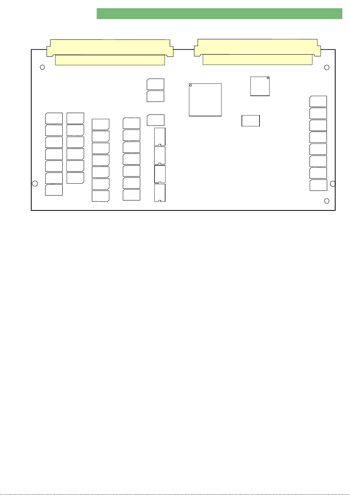
2.4 Power Board Valves PBV
Fig. : Power Board Valves
P1
P2
U3
U4
U6
U9
U13
U18
U23
2.4.1 Legend Power Boa rd Valves
P1 Valves:
Inlet Upline Tank Valve
Degassing Inlet Valve
Air Separator Valve Luftabscheide r
Dialyser Inlet Valve
Dialyser Outlet Valve
Bypass Valve
Option BIC Cartridge Valves
Disinfection Valve
Circulation Valve
Venous Tubing Clamp
Arterial Tubing Clamp
VBP
VVBE
VEB
VDE
VDA
VBICP, VBKS, VBKO, VVB
VD
VZ
SAKV
SAKA
VLA
P2 Valves:
Valve Balance Chamber
Valves Level Module
VBT, VPV, VPE, VPU, VPD, VPA
VDEBK1/2, VDABK1/2, VEBK1/2, VABK1/2
BA-TE-DE08C M.KAY
Dialog+ SW 9xx_sm_C ha pter 2_1-2010.doc/pdf < 100329> yymmdd
B. Braun Avitum AG
Page 22
Dialog
+
SW 9.xx
2. Technical System Description 1/2010 2 - 9
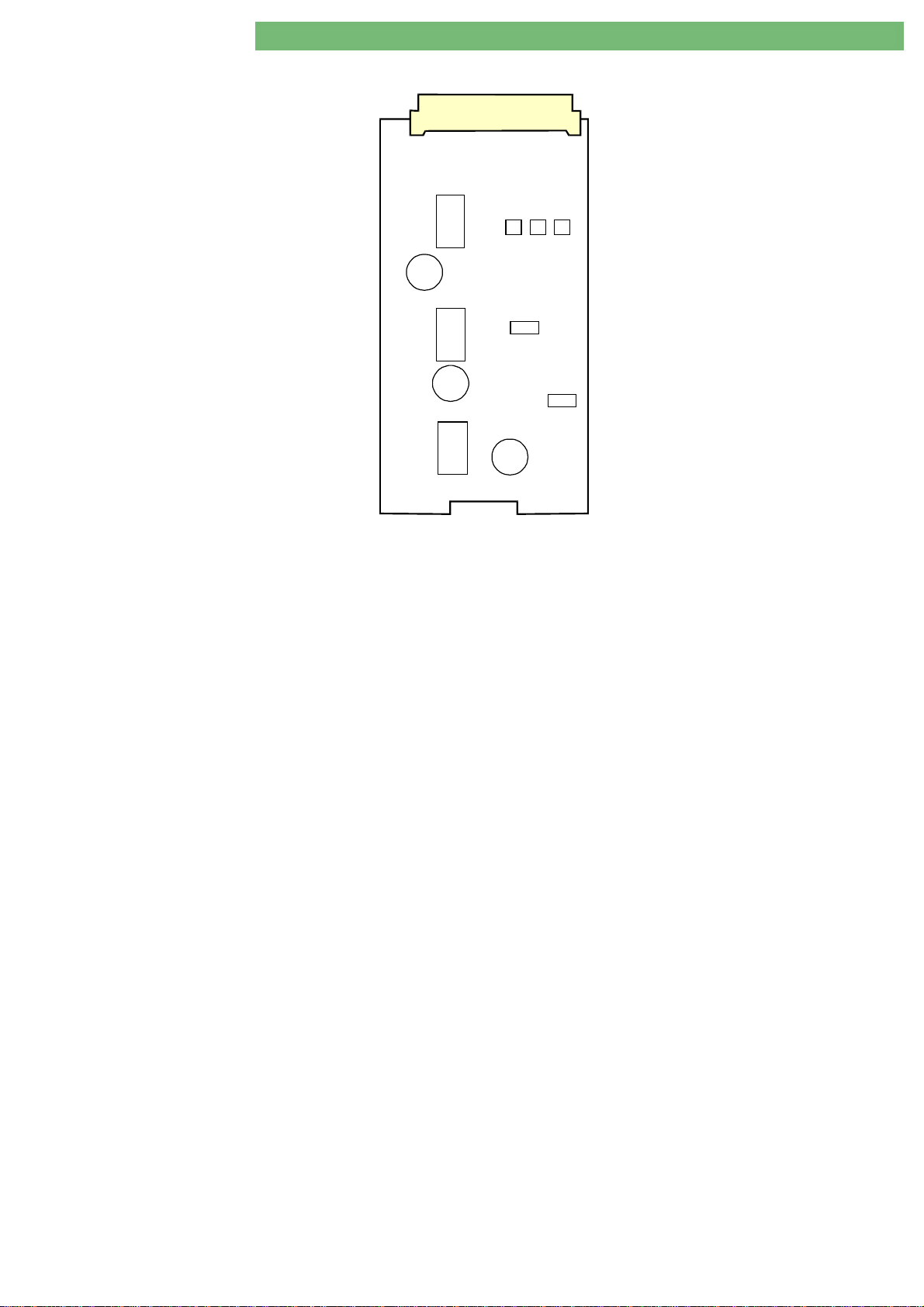
2.5 Power Board Motors PBM
P1
Fig. : Power Board Motors
2.5.1 Legend Power Board M otors
P1
P1 BIC Piston Pump BICP
P1P1
Concentrate Piston Pump KP
UF Piston Pump UFP
Level Regulation Pump (Diaphragm Pump) LRP (PPR)
BICP
BICPBICP
UFP
UFPUFP
KP
KPKP
U10
C19
U13
C26
U19
LRP (PPR)
LRP (PPR)LRP (PPR)
U2 U4 U6
U9
U12
C38
BA-TE-DE08C M.KAY
Dialog+ SW 9xx_sm_C ha pter 2_1-2010.doc/pdf < 100329> yymmdd
B. Braun Avitum AG
Page 23
+
Dialog
SW 9.xx
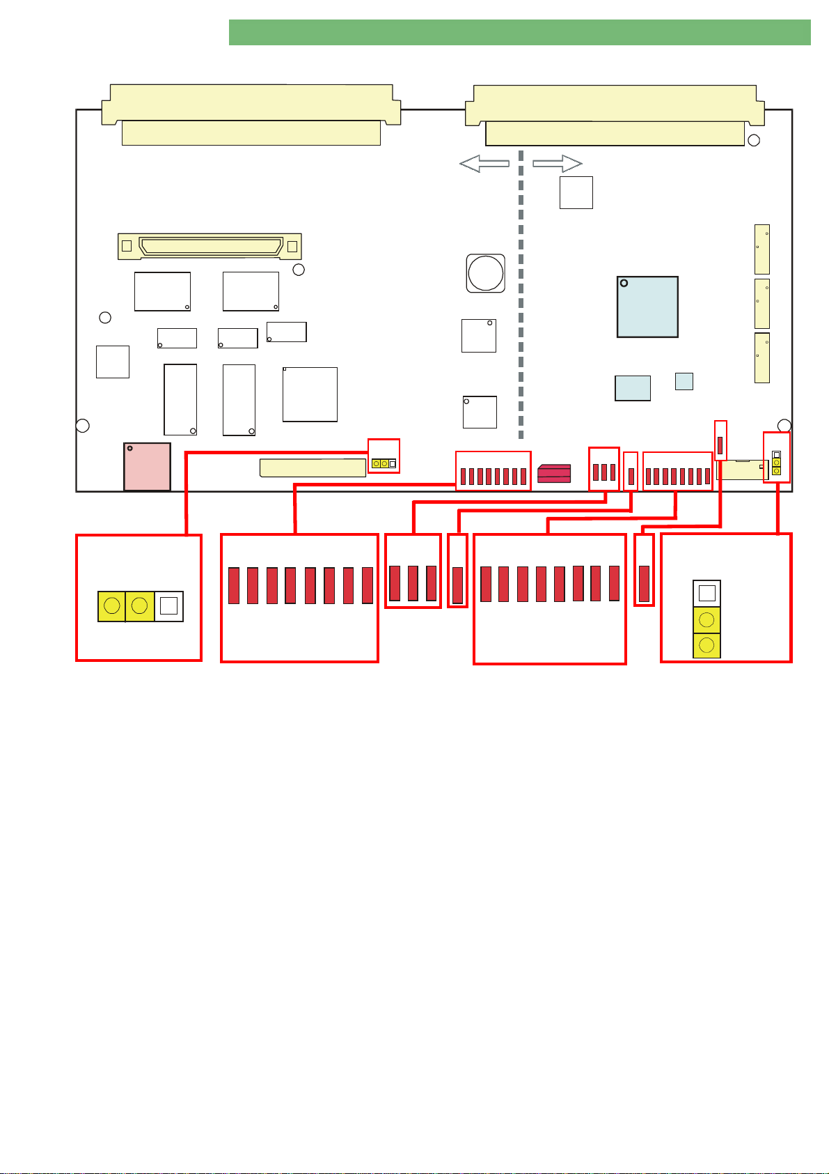
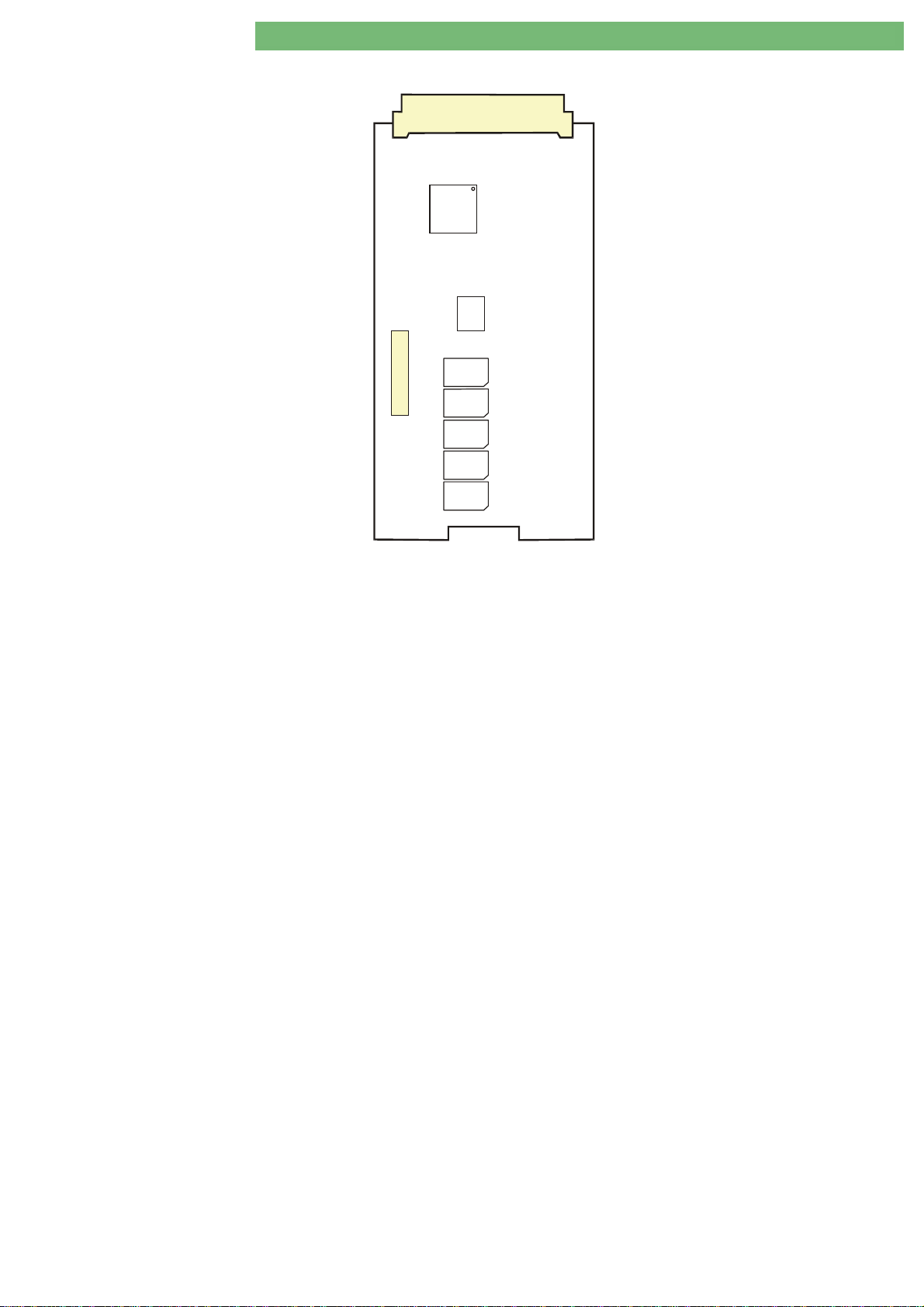
2.6 Digital Board DB
2. Technical System Description 1/2010 2 - 10
U39
U28
P11
U35
U55
P4
P1
U36
U56
U33
U43
P13
Controller
JP1
P2
Supervisor
U7
P5
L33
U30
FPGA
U27
U46
U53
S1
D16
D17
D18
D19
S1
D20
D21
D22
D23
D24
D25
D26
D27
U45
D28
D29
D34
D30
D35
D31
D32
D33
P6
P7
D13
JP2
P14
D16
D17
D18
D19
D20
D21
JP1
0123456
CWP
Fig. : Digital Board DB (LLD) with Controller and Supervisor
2.6.1 Legend Digital Board
Calibration Data
All calibration data are stored on the digital board. The
calibration data must be stored additionally on the compact flash
card CFC.
12 Bit AD Converter
Both supervisor and controller have a 12 bit AD converter with a
range of 0 to 4095.
P4/P5/P6/P7/P13/P14
USB Type A for SW installation with USB stick
P11
Supervisor Sensors:
BICPOS, KPPOS, UFPOS
Controller/Supervisor Sensors:
BKUS, SBS1, SBS2, BPS_IMP, BPA_DIR, BPV_IMP, BPV_DIR
Pumps:
BPA, BPV, EP, FPA, FPE
Controller Sensors:
NSVB, BICSS, KSS, MSBK1/2, RDV, SAD, BPADS, BPVDS,
BL (Controller/Supervisor Sensor Analog Board)
Controller
: not applicable
D28
D29
D30
D31
D32
D24
D25
D26
D22
D23
7
D27
01234567
D33
D34
Supervisor
Jumper JP1:
Jumper JP1:
Jumper JP1:Jumper JP1:
Default: Controller Write Protect CWP (for controller firmware)
Controller LEDs D13 – D20:
Controller LEDs D13 – D20:
Controller LEDs D13 – D20:Controller LEDs D13 – D20:
Status 0 – 7 for installation of LLC software
FPGA LEDs V7 – V9
FPGA LEDs V7 – V9: always ON
FPGA LEDs V7 – V9FPGA LEDs V7 – V9
Voltages for FPGA (U30) and periphery
(FPGA: Field Programmable Gate Array – configurable logical circuit)
LED V10
LED V10: flashes permanently
LED V10LED V10
Cycle time, system is running
Supervisor LEDs V11 – V18
Supervisor LEDs V11 – V18:
Supervisor LEDs V11 – V18Supervisor LEDs V11 – V18
Status 0 – 7 for installation of LLS software
LED V5
LED V5: always ON after loading
LED V5LED V5
The content of the memory (U45) is loaded to FPGA (U30) during
switch-on. The therapy program and the service program is stored
in the RAM (U45).
Jumper JP2:
Jumper JP2:
Jumper JP2:Jumper JP2:
Default: Supervisor Write Protect SWP (for supervisor firmware)
S1 Service Switch:
Position 0:
Position 2:
Position 3:
Therapy Mode
TSM Service Program Mode
Software Installation/Update Mode
D13
D35
JP2
SWP
BA-TE-DE08C M.KAY
Dialog+ SW 9xx_sm_C ha pter 2_1-2010.doc/pdf < 100329> yymmdd
B. Braun Avitum AG
Page 24
+
Dialog
SW 9.xx
2.7 Analog Board AB
2. Technical System Description 1/2010 2 - 11
U35
Fig. : Analog Board AB (LLA)
U36 U37
P1
U32
U40
U41
U42
U46
U39
U43
U47
U21
U33
U38
U29
P2
U44
U48
U50
U28
U45
U49
2.7.1 Legend Analog Board
P1/P2
Controller Sensors:
PBS, TSHE, TSE, TSB IC, TSD, TSDE, BICLF, ENDLF, PE, LAFS
Supervisor Sensors:
TSD-S, ENDLF-S
Controller/Supervisor Sensors:
BL, PBE, PA, PV, PDA
BA-TE-DE08C M.KAY
Dialog+ SW 9xx_sm_C ha pter 2_1-2010.doc/pdf < 100329> yymmdd
B. Braun Avitum AG
Page 25
Dialog
+
SW 9.xx
2. Technical System Description 1/2010 2 - 12
2.8 HDF Online Board HOB
P1
U2
U5
P4
Fig. : HDF Online Board
2.8.1 Legend HDF Online Board
Sensors:
P1:
PSABFS, PSAUS, PSPOSS, FEHDFS, FEDFFS P4
: Valves
VBE, VDFF, VSAA, VSAE, VSB
BA-TE-DE08C M.KAY
Dialog+ SW 9xx_sm_C ha pter 2_1-2010.doc/pdf < 100329> yymmdd
B. Braun Avitum AG
Page 26
+
Dialog
SW 9.xx
2.9 UF Sub-Rack
MSBKB1/2
2. Technical System Description 1/2010 2 - 13
VDEBK1
VDA
VLA
VEBK1
LA
VABK2
MSBK2
VDEBK2
DDE
RVFPA
VLA
VBP
VEBK2
LA
VABK1
VDABK2
VABK1
VBP
DDE
RVFPA
VDEBK2
MSBKB1/2
VABK2
VDEBK1
Fig. : UF Sub-Rack
2.9.1 Legend UF Sub-Rack
Balance Chamber BK1/2
Bypass Valve VBP
Throttle Dialyser Inlet DDE
Air Separator LA
Membrane Position Sensor Balance Chamber Board MSBKB1/2
Membrane Position Sensor Balance Chamber MSBK1/2
Non-Return Valve Outlet Flow Pump RVFPA
Outlet Balance Chamber Valve VABK1
VBP
VBPVBP
LA
LALA
BK1/2
BK1/2BK1/2
DDE
DDEDDE
VABK1
VABK1VABK1
RVFPA
RVFPARVFPA
VDA
MSBKB1/2
MSBKB1/2MSBKB1/2
MSBK1/2
MSBK1/2MSBK1/2
VEBK1
Outlet Balance Chamber Valve VABK2
Outlet Dialyser Balance Chamber Valve VDABK1
Outlet Dialyser Balance Chamber Valve VDABK2
Inlet Dialyser Balance Chamber Valve VDEBK1
Inlet Dialyser Balance Chamber Valve VDEBK2
Inlet Balance Chamber Valve VEBK1
Inlet Balance Chamber Valve VEBK2
Air Separator Valve VLA
VDABK1
VEBK1
VEBK1VEBK1
VEBK2
VEBK2VEBK2
VLA
VLAVLA
VABK2
VABK2VABK2
VDABK1
VDABK1VDABK1
VDABK2
VDABK2VDABK2
VDEBK1
VDEBK1VDEBK1
VDEBK2
VDEBK2VDEBK2
BA-TE-DE08C M.KAY
Dialog+ SW 9xx_sm_C ha pter 2_1-2010.doc/pdf < 100329> yymmdd
B. Braun Avitum AG
Page 27
Dialog
+
SW 9.xx
2. Technical System Description 1/2010 2 - 14
2.10 UF Sub-Rack HDF Online
VBE
MSBKB1/2
VABK2
MSBK2
VDEBK2
DDE
VDEBK1
VDABK2
VDA
LA
HFB
VSB
VEBK1
VSAE
VSAA
VSAE
VEBK2
VBP
VABK1
VSAA
VABK1
VLA
LA
DDE
RVFPA
VDEBK2
RVFPA
Fig. : UF Sub-Rack HDF Online
2.10.1 Legend U F Sub-Rack HDF Online
Balance Chamber BK1/2
Bypass Valve VBP
Throttle Dialyser Inlet DDE
Hydrophobic Vent Filter HFB
Air Separator LA
Membrane Position Sensor Balance Chamber Board MSBKB1/2
Membrane Position Sensor Balance Chamber MSBK1/2
Non-Return Valve Outlet Flow Pump RVFPA
Outlet Balance Chamber Valve VABK1/2
VBP
VBPVBP
LA
LALA
BK1/2
BK1/2BK1/2
DDE
DDEDDE
HFB
HFBHFB
VLA
VABK1/2
VABK1/2VABK1/2
VBP
RVFPA
RVFPARVFPA
VDA
MSBKB1/2
MSBKB1/2MSBKB1/2
MSBK1/2
MSBK1/2MSBK1/2
HFB
VEBK1
MSBKB1/2
VABK2
VDEBK1
VBE
VDABK1
VSB
Outlet Dialyser Balance Chamber Valve VDABK1/2
Inlet Dialyser Balance Chamber Valve VDEBK1/2
Inlet Balance Chamber Valve VEBK1/2
Air Separator Valve VLA
Additional Co
Substitute Bypass Valve VSB
Substitute Connection Outlet Valve VSAA
Substitute Connection Inlet Valve VSAE
Filter Vent Valve VBE
VLA
VLAVLA
mponents
mponents
mponents mponents
VBE
VBEVBE
VEBK1/2
VEBK1/2VEBK1/2
for HDF Online:
VSB
VSBVSB
VDABK1/2
VDABK1/2VDABK1/2
VDEBK1/2
VDEBK1/2VDEBK1/2
VSAA
VSAAVSAA
VSAE
VSAEVSAE
BA-TE-DE08C M.KAY
Dialog+ SW 9xx_sm_C ha pter 2_1-2010.doc/pdf < 100329> yymmdd
B. Braun Avitum AG
Page 28
+
Dialog
SW 9.xx
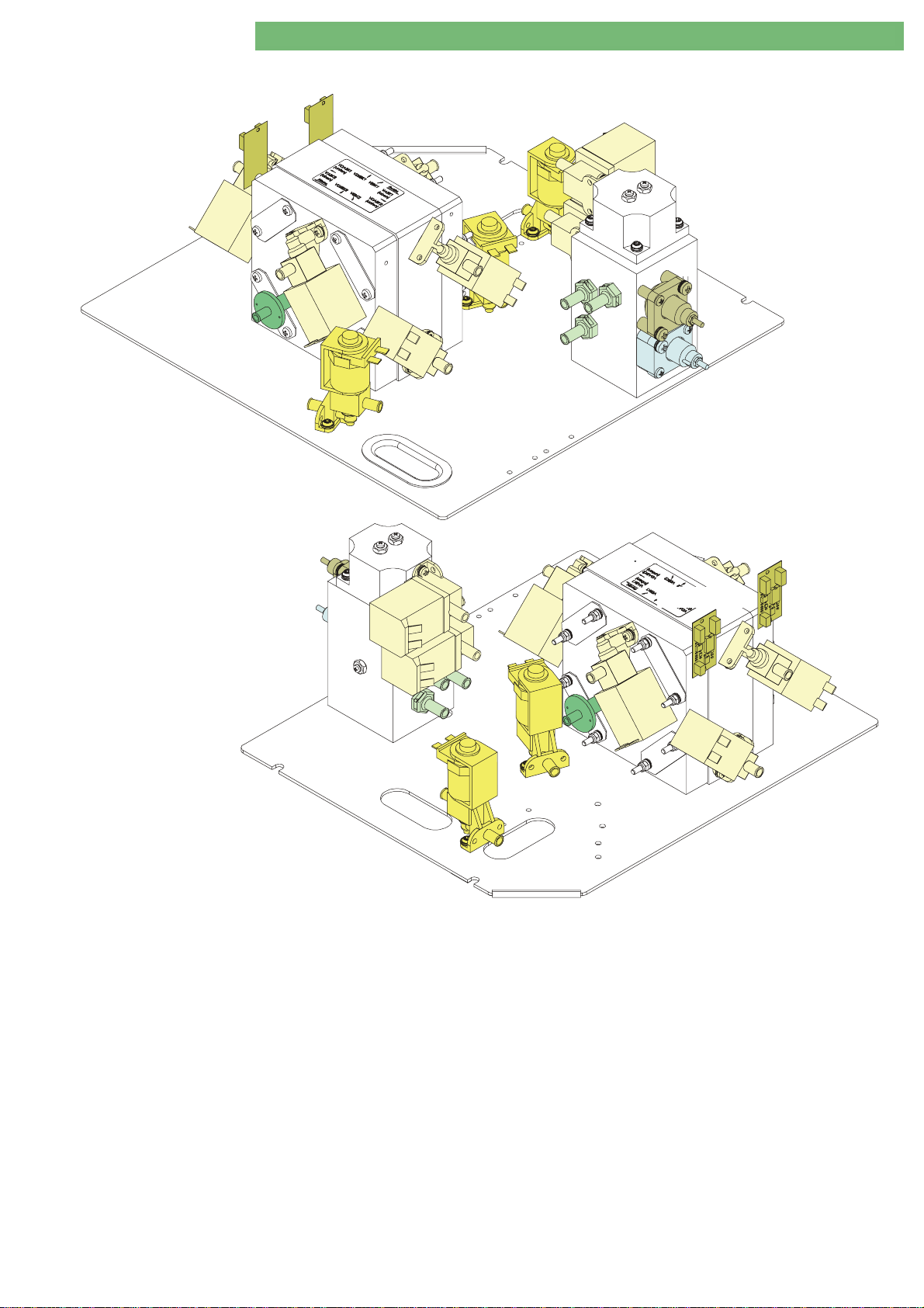
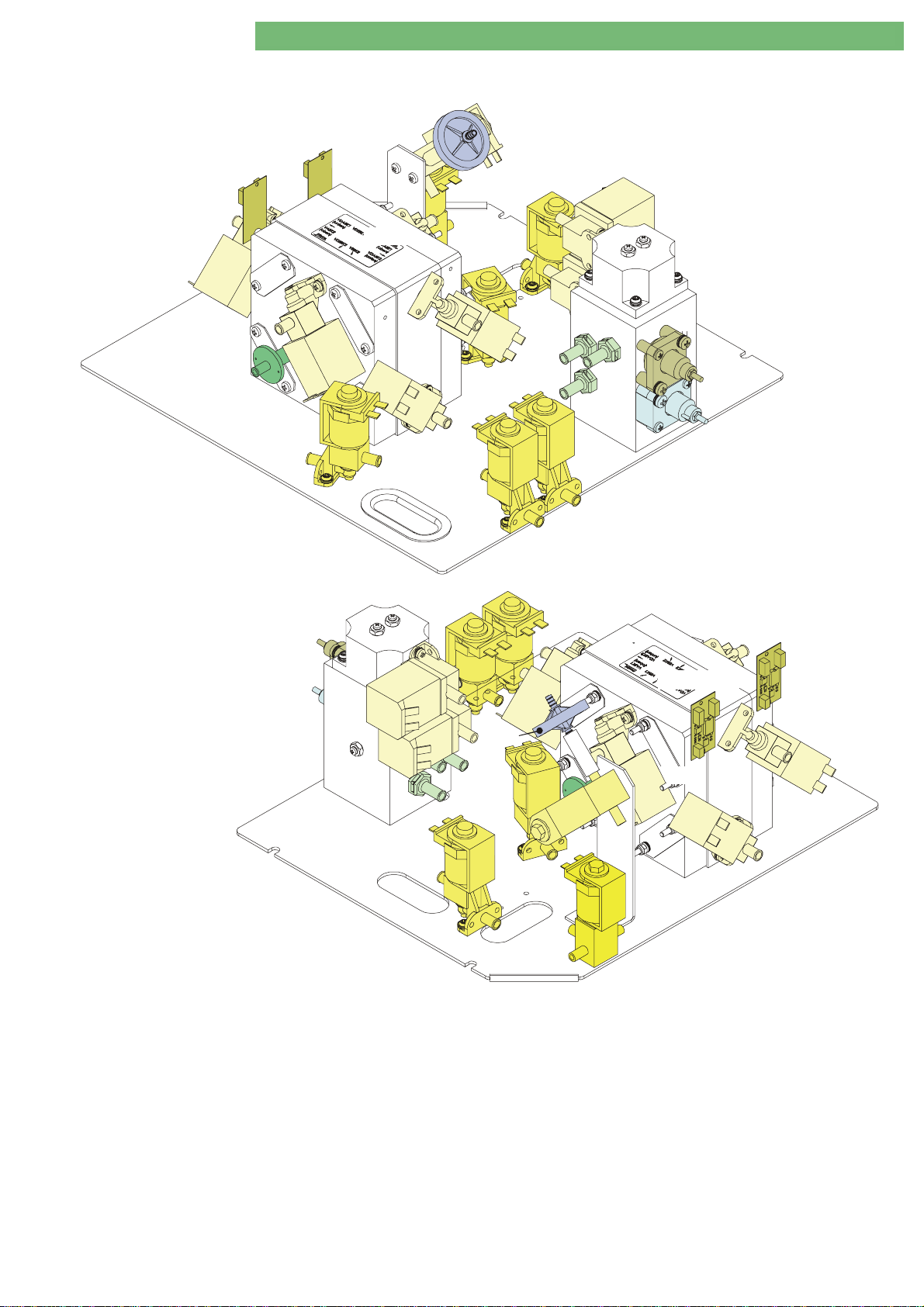
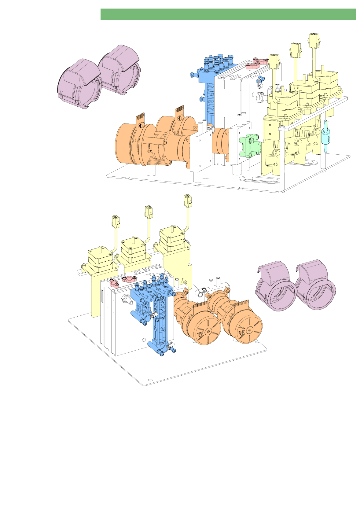
2.11 DF Sub-Rack
2. Technical System Description 1/2010 2 - 15
A
FPA
FPE
KP
ENDLF
BICLF
RVK
TSDS
RVFPE
RVB
BICP
UFP
KP
RFUFP
BICP
RVB
Fig. : DF Sub-Rack
2.11.1 Legend DF Sub-Rack
RVK
UFP
BICLF
TSBIC
ENDLF
TSD
FPE
A
FPA
BIC Pump BICP
Degassing Pressure Sensor PE
END Conductivity/Supervisor ENDLF/ENDLF-S
Outlet Flow Pump FPA
Inlet Flow Pump FPE
Concentrate Pump KP
Bicarbonate Conductivity Sensor BICLF
Bicarbonate Non-Return Valve RVB
BA-TE-DE08C M.KAY
BICP
BICPBICP
PE
PEPE
ENDLF/ENDLF-S
ENDLF/ENDLF-SENDLF/ENDLF-S
FPA (Motor Cover AAAA)
FPAFPA
FPE (Motor Cover AAAA)
FPEFPE
KP
KPKP
BICLF
BICLFBICLF
RVB
RVBRVB
Dialog+ SW 9xx_sm_C ha pter 2_1-2010.doc/pdf < 100329> yymmdd
Non-Return Valve Flow Pump Inlet RVFPE
Non-Return Valve Concentrate RVK
Non-Return Valve UF Pump RFUFP
Bicarbonate Temperature Sensor TSBIC
Dialysate Temperature Sensor TSD
Dialysate Supervisor Temperature Sensor TSD-S
UF Pump UFP
UFP
UFPUFP
RVK
RVKRVK
RFUFP
RFUFPRFUFP
TSD
TSDTSD
RVFPE
RVFPERVFPE
TSBIC
TSBICTSBIC
TSD-S
TSD-STSD-S
B. Braun Avitum AG
Page 29
+
Dialog
SW 9.xx
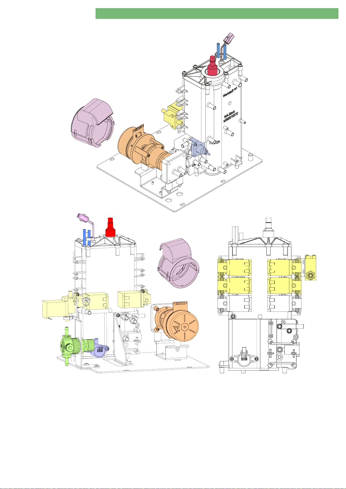
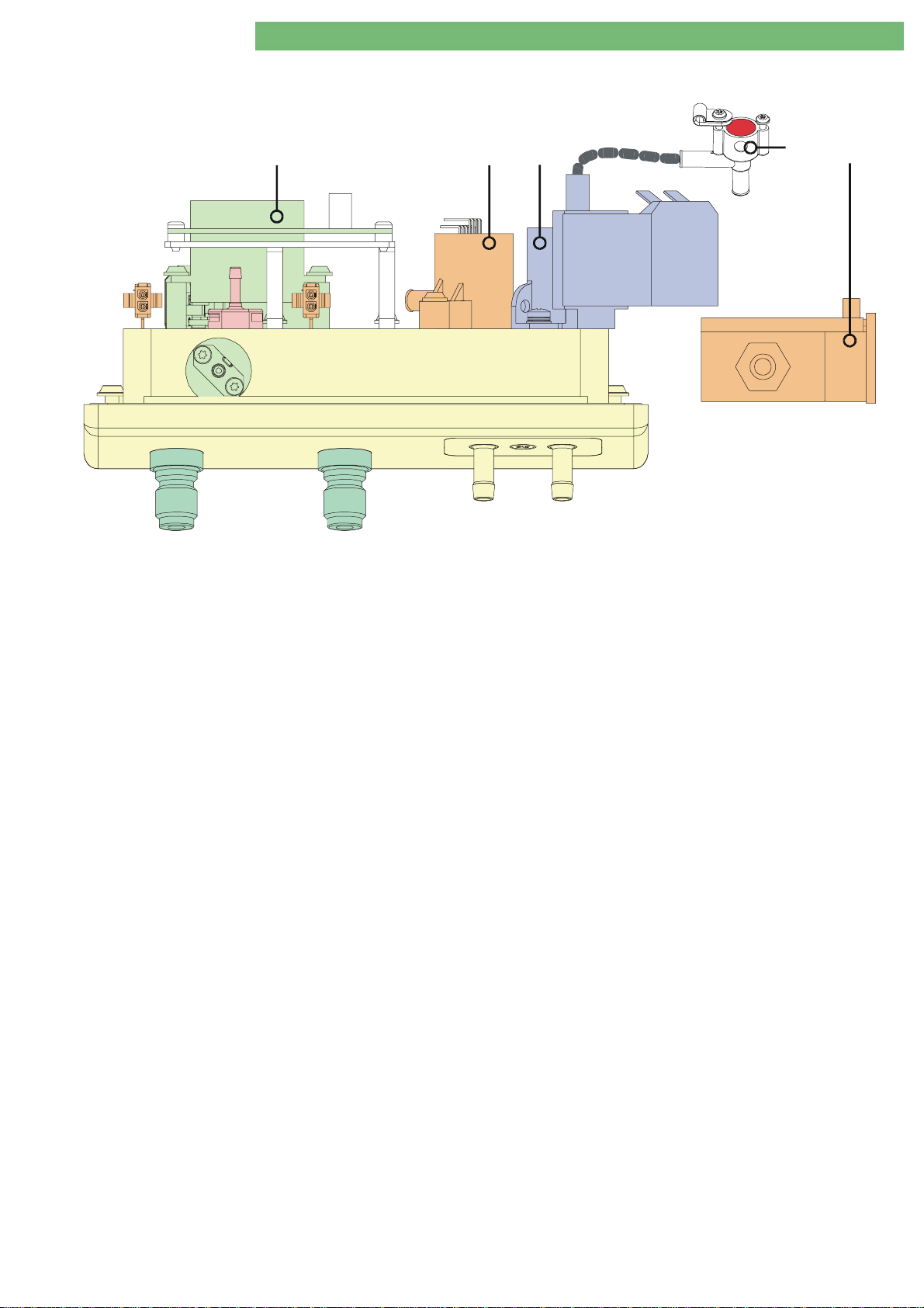
2.12 Water Sub-Rack
A
2. Technical System Description 1/2010 2 - 16
NSVB
WT
H
WAB
VEB
NSVB
VVBE
WT
EP
H
WA-Block
VZ
VEB
A
EP
RVDA
VBKS
VBICP
VZ
DBK
VBKO
VVB
VEB
DMV
PE
PE
Fig. : Water Sub-Rack Fig. : Water Block with Valves for BIC Option
2.12.1 Legend Wat er Sub -Ra c k
Water Block WAB
VB
VB and Heat Exchanger WT
VBVB
Pressure Reducer DMV
Degassing Pressure Sensor PE
Degassing Chamber EK
Degassing Pump EP
Heater HHHH
Degassing Temperature S e nso r TSE
Heater Temperature Sensor TSH
Heater Inlet Temperature Sensor TSHE
BA-TE-DE08C M.KAY
WAB (with integrated Degassing Chamber EK
WABWAB
WT)
WTWT
DMV
DMVDMV
PE
PEPE
EK
EKEK
EP (Motor Cover AAAA)
EPEP
TSE
TSETSE
TSH
TSHTSH
TSHE
TSHETSHE
Dialog+ SW 9xx_sm_C ha pter 2_1-2010.doc/pdf < 100329> yymmdd
EK, Upline Tank
EKEK
Upline Tank Inlet Valve VVBE
Upline Tank VB
Additional Components for Option BIC Cartridge:
Additional Components for Option BIC Cartridge:
Additional Components for Option BIC Cartridge:Additional Components for Option BIC Cartridge:
Throttle BIC Cartridge Holder DBK
BIC Concentrate Suction Rod Valve VBKS
Top BIC Cartridge Valve VBKS
BIC Pump Valve VBICP
Upline Tank Valve VVB
VB
VBVB
VBICP
VBICPVBICP
VVB
VVBVVB
VVBE
VVBEVVBE
VBKS
VBKSVBKS
DBK
DBKDBK
VBKS
VBKSVBKS
B. Braun Avitum AG
Page 30
+
Dialog
2.13 Rinsing Bridge
SW 9.xx
2. Technical System Description 1/2010 2 - 17
VD
Fig. : Rinsing Bridge
2.13.1 Legend Rinsing Bridge
1
23
PDA
54
TSDE
VDE
BL
1111 Disinfection Valve VD
2222 Pressure Sensor Dialysate Outlet PDA
3333 Dialyser Inlet Valve VDE
VD
VDVD
VDE
VDEVDE
PDA
PDAPDA
4444 Temperature Sensor Dialyser Inlet TSDE
5555 Blood Leak Detector BL
BL
BLBL
TSDE
TSDETSDE
BA-TE-DE08C M.KAY
Dialog+ SW 9xx_sm_C ha pter 2_1-2010.doc/pdf < 100329> yymmdd
B. Braun Avitum AG
Page 31

+
Dialog
SW 9.xx
2.14 Rear Door
2. Technical System Description 1/2010 2 - 18
3
12
4
Fig. : Rear Door
2.14.1 Legend Rear Doo r
Switch Mode Power Supply Microcontroller SMPS-MC
1.
2.
Fan
SMPS-MC
SMPS-MC
SMPS-MCSMPS-MC
Mains Switch
3.
Mains Cord
4.
BA-TE-DE08C M.KAY
Dialog+ SW 9xx_sm_C ha pter 2_1-2010.doc/pdf < 100329> yymmdd
B. Braun Avitum AG
Page 32

Dialog
+
SW 9.xx
2. Technical System Description 1/2010 2 - 19
2.15 Switch Mode Power Supply
Microcontroller SMPS-MC
P12
P10
P4
H401
H303
H301
H302
H304
H601
H602
H402
H403
F401
F303
F301
F302
F304
F601
F602
F402
F403
H104
-
H300
K3
F600
+
+24VGB / T3.15A TR5
+24 VGD / T3.15A TR5
H600
P5
X104
H900
P8
C115
+
K4
-
C114
+
+12VAN / T1.25A TR5
+24VL / M10.00A TR5
-
X100
XP3.2
XP3.1
X103
P2
P6
P9
P14
X903
GNDAKKU
+24VAKKU
P7
P11
X101
+12VD / T3.15A TR5
+5VD / T3.15A TR5
+5VD / T3.15A TR5
+5VD / T5.00A TR5
+5VD / T3.15A TR5
+12VD / T5.00A TR5
BENNING XXXXX XXXXXX XXXXXX
Netzgerät/Power Supply
NT-Dialog-MC
XXXXXXXX
SN/SNo: XXXXXXX Bj/Year: XX/XX
TN /Item-No:XXXX XX.5 Ver/SW: Rev 1.15
Opt.: Art/mode: XX/xx
Eingang/Input Ausgang/Output
Art/Kind AC DC
Hz 50-60
V 110/12 0/230/240
A 5/2,3
H401
H303
H301
H302
H304
H601
H602
H402
H403
F401
F303
F301
F302
F304
F601
F602
F402
F403
H300
F600
F1 T6.25A 6.3x32 (X1.1: L)
F2 T6.25A 6.3x32 (X1.1: L)
F5A 110/120V: F12A 6.3x32 (X1.6: HZG1-L)
230V: T6.25A 6.3x32 (X1.6: HZG1-L )
F5B 110/120V: F12A 6.3x32 (X1.7: HZG2-L)
230V: T6.25A 6.3x32 (X1.7: HZG2-L )
F6 110/120V: F20A 6.3x32 (X1 . 5: HZG-N)
230V: F12A 6.3x32 (X1.5: HZG-N)
F301 T3.15A TR5 (+5VD1)
F302 T5.0A TR5 (+5VD2)
F303 T3.15A TR5 (+5VD3)
F304 T3.15A TR5 (+5VD4)
F401 T3.15A TR5 (+12VD1)
F402 T5.00A TR5 (+12VD2)
F403 T1.25A TR5 (+12VA)
F600 M10.00A 6.3x32 (+24VL)
F601 T3.15A TR5 (+24VGB)
F602 T3.15A TR5 (+24VGD)
H600
F5A
F5B
X1.6
LH1 LH2
F2
F1
F6
X1.3
X1.5
N
X1.4
PE1
X1.1
X1.2
LNPE
X1.8
PE
X1.7
Fig. : Switch Mode Power Supply Microcontroller SMPS-MC
2.15.1 Legend Switch Mode Power Supply
Microcontroller
X1.1
X1.1 Mains Input L
X1.1X1.1
X1.2
X1.2 Mains Input N
X1.2X1.2
X1.3
X1.3 Mains Input PE
X1.3X1.3
X1.4
X1.4 Heater PE1
X1.4X1.4
X1.5
X1.5 Heater N
X1.5X1.5
X1.6
X1.6 Heater LH1
X1.6X1.6
X1.7
X1.7 Heater LH2
X1.7X1.7
X1.8
X1.8 PE
X1.8X1.8
P2
P2 Power Supply Control from Low Level Digital Board/Basic Board
P2P2
XP3
XP3 Battery Connection (Screw Terminal)
XP3XP3
P4
P4 24 V Voltages
P4P4
F1/F2
F1/F2 6.25 AT (6.3x32), Mains Input
F1/F2F1/F2
F5A/F5B
F5A/F5B 12 AF (6.3x32), Heater 1800 W (110/ 120 V )
F5A/F5BF5A/F5B
6.25 AT (6.3x32), Heater 1800 W (230/ 240 V )
F6
F6 20 AF (6.3x32), Heater 1800 W (110/120 V)
F6F6
12 AF (6.3x32), Heater 1800 W (230/ 240 V )
F301
F301 3.15 AT (TR5), +5 VD
F301F301
F302
F302 5.00 AT (TR5), +5 VD
F302F302
Type Plate SMPS-MC
TN/Item-No (Version Numb er SM P S-M C) :
TN/Item-No (Version Numb er SM P S-M C) : e.g. XXXXXX.5 Ver/SW (SW Version):
TN/Item-No (Version Numb er SM P S-M C) :TN/Item-No (Version Numb er SM P S-M C) :
P5
P5 12 V Voltages
P5P5
P7
P7 ABPM Option
P7P7
P8
P8 DSI Option
P8P8
P9
P9 Fan, Mains Switch
P9P9
P10
P10 Motherboard, Front Panel Board
P10P10
P12
P12 Options
P12P12
P13
P13 -
P13P13
P14
P14 EXT EIN
P14P14
P101
P101 Service Watchdog
P101P101
X100
X100 Fan
X100X100
F303/F304
F303/F304 3.15 AT (TR5), +5 VD
F303/F304F303/F304
F401
F401 3.15 AT (TR5), +12 VD
F401F401
F402
F402 5.00 AT (TR5), +12 VD
F402F402
F403
F403 1.25 AT (TR5), +12 VAN
F403F403
F600
F600 10 AM (6.3x32), +24 VL
F600F600
F601/F602
F601/F602 3.15 AT (TR5), +24 VGB
F601/F602F601/F602
Ver/SW (SW Version): e.g. Rev. 1.15
Ver/SW (SW Version):Ver/SW (SW Version):
BA-TE-DE08C M.KAY
Dialog+ SW 9xx_sm_C ha pter 2_1-2010.doc/pdf < 100329> yymmdd
B. Braun Avitum AG
Page 33

+
Dialog
SW 9.xx
2.16 TFT Monitor
2. Technical System Description 1/2010 2 - 20
Fig. : TFT Monitor
2.16.1 Legend TF T M onitor
Backlight Inverter Board
Front Panel Board
BA-TE-DE08C M.KAY
TFT Monitor
FPB
TFT
Dialog+ SW 9xx_sm_C ha pter 2_1-2010.doc/pdf < 100329> yymmdd
BIB
Optical Status Display Board
Touch Controller Board
Touch Screen
TCB
OSDB
B. Braun Avitum AG
Page 34

+
Dialog
SW 9.xx
2.17 Front Door
2. Technical System Description 1/2010 2 - 21
HP
PV PA PBS/SN PBE
SN
SN
PBA PBV
SAD
SAKV-SG
SAKA
SN
SAD
HP
PV PA
SN
PBA PBV
SAKASAKV-SG
2222
Fig. : Front Door with Double Pump Fig. : Front Door for HDF Online
1111
PBS/SN
PBE
2222
PA
LRM
HP
PV
SAD
SAKV-SG
PBE
2
22
LRP
PBS/SN
PBV
1111
LRP
PBE
PBV
22222
Fig. : Front Door (Inside) with Double Pump Fig. : Front Door (Inside) for HDF Online
PBS/SN
PBA
SAKA
PBA
SAKA
PA
LRM
HP
PV
SAD
SAKV-SG
2.17.1 Legend Front Door
Cover for Suction Rods 2222
Arterial Blood Pump BPA
Venous Blood Pump BPV
Pressure Sensor PBE
Pressure Sensor PBS/SN
PBE
PBEPBE
PBS/SN
PBS/SNPBS/SN
Arterial Pressure Sensor PA
Venous Pressure Sensor PV
BA-TE-DE08C M.KAY
Dialog+ SW 9xx_sm_C ha pter 2_1-2010.doc/pdf < 100329> yymmdd
BPA
BPABPA
BPV
BPVBPV
PA
PAPA
PV
PVPV
Heparin Pump Compact HP
Arterial Tubing Clamp SAKA
Venous Tubing Clamp Current Closed SAKV-SG
Safety Air Detector SAD
HP
HPHP
SAKA
SAKASAKA
SAKV-SG
SAKV-SGSAKV-SG
SAD/Venous Red Detector RDV
SADSAD
Substitution Port 1111
Connection for concentrat e S uct i o n R o d s 2222
B. Braun Avitum AG
RDV
RDVRDV
Page 35

Dialog
+
SW 9.xx
2. Technical System Description 1/2010 2 - 22
2.18 Level Regulation Module
HFE
PBS
PBE
LRP
HFS
HFP
P1
P2
V
P
E
V
P
D
V
P
U
V
P
V
P3
V
P
A
V
B
T
HFV
HFA
PV
PA
HFA
PA PV PBS PBE
HFV
PA
Fig. : Level Regulation Module and Level Regulation Pump
2.18.1 Legend Level Regula t ion Module
There are two level regulation modules with different assemblies, i.e. for machines with a sin gle blood pump and with a
double blood pump.
Inlet Pressure Sensor Valve VPE
Down Pressure Sensor Valve VPD
Up Pressure Sensor Valve VPU
Blood Control Pressure Sensor Valve VPS
Venous Pressure Sensor Valv e VPV
Arterial Pressure Sensor Valve VPA
Blood Side Test Pressure Sensor Valve VBT
PV PBE
VPE
VPEVPE
VPD
VPDVPD
VPU
VPUVPU
VPV
VPVVPV
VPA
VPAVPA
LRP
VPS (Double Pump)
VPSVPS
VBT
VBTVBT
HFS
IN
OUT
P
P
HFE
PBS
P
IN
P
OUT
Arterial Hydrophobic Filter HFA
Venous Hydrophobic Filter HFV
Blood Control Pressure Hydrophobic Filter HFS
(Double Pump)
Inlet Hydrophobic Filter HFE
Pump Hydrophobic Filter (Ceramic Filter) HFP
HFE
HFEHFE
HFA
HFAHFA
HFV
HFVHFV
HFS
HFSHFS
HFP
HFPHFP
BA-TE-DE08C M.KAY
Level Regulation Pump LRP
LRP
LRPLRP
Dialog+ SW 9xx_sm_C ha pter 2_1-2010.doc/pdf < 100329> yymmdd
B. Braun Avitum AG
Page 36

Dialog
+
SW 9.xx
2. Technical System Description 1/2010 2 - 23
2.18.2 Flow Diagram Level
Regulation
Module
Front Door
Outside
Inside
HFA
HFV
HFE
HFS
1
3
VBT
2
PA
PV
PBE
PBS
2
1
3
VPA
2
1
3
VPV
1
2
3
VPE
Level Module
1
3
1
3
VPD
VPU
HFP
P
IN
2
LRP
2
OUT
P
PA Chamber PV Chamber
Fig. : Flow Diagram Level Regulation Module
PBE Chamber
3/2 Way Solenoid Valve
There are two level regulation modules with different assemblies, i.e. for
machines with a single blood pump and with a double blood pump. The level
regulation module and the level regulation pump
inside of the rear door. The level regulation module and
functions;
Setting of the level in all blood side chambers (3/2 way solenoid valves
•
VPV, VPE, VPU, VPD
Monitoring of the blood side pressures (pressure sensors PA, PV,
•
)
PBS
Test of the blood side pressure sensors in preparation (3/2 way solenoid
•
valve
VBT
)
and diaphrag m pump
LRP
are assembled on the
LRP
have the following
LRP
)
PBE
VPA
and
,
BA-TE-DE08C M.KAY
Dialog+ SW 9xx_sm_C ha pter 2_1-2010.doc/pdf < 100329> yymmdd
B. Braun Avitum AG
Page 37

+
Dialog
SW 9.xx
2.19 Flow Diagrams
2.19.1 Dialog+
2. Technical System Description 1/2010 2 - 24
V
Z.D.
PEV*
A
Dialyser
V.D.
FVD
SB1
SB2
Rinsing Bridge
UF Sub-Rac k
DF Sub-Rack
PDA
BL
T
VBP
VLA
LAFS
FBK2
VDABK2
VABK1
DDE VDETSDE
BK1
Balance Chamber
VDEBK1
8
RVFPE
FPE
TSD-S
ENDLF-S
ENDLFBICLFTSBIC
T T
TSD
T
VABK2
VDABK1
MSBK1
VEBK1
FBK1
RVK
VEBK2
VDEBK2
D
KP
C
SBS1
Air
VDA
LA
8
FPA
B
C
BK2
MSBK2
RVDA
SBS2
M
VD
LVD
RVFPA
UFP
RVUFP
Supply
KVABV A
Central Concentrate
KE
FKFB
KSS
VZ
SKKSSKBS
SS
BIC
BE
Supply
Central Bicarbonate
FD
(Unit Rear)
Disinfectant
KE
Acid Concentrate
BE
BIC Concentrate
KSB KSK
Disinfectant
Blood Venous
Housing
Dialysate Outlet
Water Inlet
BA-TE-DE08C M.KAY
AB
RVB
BICP
T
TSE
WAB
T
H
NSVB
Water Sub-Rack
VB WT
DMV
VVBE
EK
TSH
PE
T
A
D
TSHE
FEP
Dialog+ SW 9xx_sm_C ha pter 2_1-2010.doc/pdf < 100329> yymmdd
Air
Dialysate Flow 2
Dialysate
Blood Arterial
8
EP
VEB
Bicarbonate
Water
Concentrate
Dialysate Flow 1
B. Braun Avitum AG
Page 38

Dialog
+
SW 9.xx
2. Technical System Description 1/2010 2 - 25
2.19.2 Dialog+ with BIC Option and DF Filter Option
VA
Z.D.
PEV*
Dialyser
V.D.
FVD
SB1
SB2
SBS1
M
VD
Air
VDA
LA
8
FPA
B
C
BK2
RVDA
VLA
VABK2
VDEBK2
PDA
BL
LAFS
FBK2
VDABK2
MSBK2
VEBK2
RVFPE
TSDE
DF Filter *
DDE
VDE
T
VBP
VABK1
VDABK1
BK1
Balance Chamber
TSD-S
MSBK1
VEBK1
VDEBK1
FBK1
8
FPE
T
ENDLF-S
Rinsing Bridge
Rear DoorWater Sub-Rack
SBS2
LVD
RVFPA
UFP
RVUFP
Supply
KVA
Central Conc en tr a te
KE
FKFB
KSS
VZ
SKKSSKBS
FD
(Unit Rear)
Disinfectant
KE
Acid Concentrate
*
ENDLFBICLFTSBIC
WAB
VB WT
EK
D
C
RVK
AB
RVB
T
KP
Kt/V-UV*
BICP
VBICP*
VBKO*
TSH
T
A
D
TSHE
PE
FEP
T
TSD
DF Sub-Rack UF Sub-Rack
DBK*
Dialysate Outlet
Water Inlet
DMV
VVBE
T
T
TSE
H
NSVB
SS
BIC
VBKS
BVA
FBIC
RVBO*
VVB*
8
EP
VEB
BE
BIC Co n centr ate
BE
Supply
Central Bi car b ona t e
KSB KSK
Disinfectant
Blood Venous
SPA
BKUS
Dialysate Flow 2
RVBU
Water
Housing
Options
Air
Dialysate
Bicarbonate
Blood Arter ial
Concentrate
Dialysate Flow 1
BA-TE-DE08C M.KAY
Dialog+ SW 9xx_sm_C ha pter 2_1-2010.doc/pdf < 100329> yymmdd
B. Braun Avitum AG
Page 39

Dialog
+
SW 9.xx
2. Technical System Description 1/2010 2 - 26
2.19.3 Dialog+ HDF Online
PSAUS
VSAEVSB
Front Door
PSABF
VSAA
FSU
VA
Z.D.
PEV*
Dialyser
V.D.
FVD
SB1
SB2
HFB
PDA
VDE
Rinsing Bridge
T
VBP
TSDE
VBE
HDF Filter
DF Filter
Rear Door
UF Sub-Rack
DDE
VDFF
VABK1
VDABK1
BK1
Balance Chamber
RVFPE
TSD-S
MSBK1
VEBK1
VDEBK1
FBK1
8
FPE
T
ENDLF-SENDLF
BL
VLA
LAFS
FBK2
VDABK2
VABK2
VEBK2
VDEBK2
SBS1
Air
VDA
LA
8
FPA
B
C
BK2
MSBK2
RVDA
SBS2
M
VD
LVD
RVFPA
UFP
RVUFP
Supply
KVABVA
Central Concentra te
KE
FK
KSS
VZ
SKKSSKBS
FD
(Unit Rear)
Disinfectant
KSK
KE
Acid Concentrate
*
FB
SS
FEP
BIC
VBKS
FBIC
RVBO*
VVB*
8
EP
VEB
T
TSD
DF Sub-Rack
DBK*
Dialysate Outlet
Water Sub-Rack
Water Inlet
DMV
VVBE
BICLFTSBIC
T
T
TSE
H
NSVB
WT
VB
EK
RVK
RVB
WAB
KP
CD
AB
BICP
VBICP*
T
TSH
T
A
D
PE
Kt/V-UV*
TSHE VBKO*
BE
BIC Concentrate
BE
Supply
Central Bicarbonate
KSB
Disinfectant
Blood Venous
SPA
BKUS
Dialysate Flow 2
RVBU
Water
Housing
Options
AirConcentrate
Dialysate
Bicarbonate
Blood Arterial
Dialysate Flow 1
BA-TE-DE08C M.KAY
Dialog+ SW 9xx_sm_C ha pter 2_1-2010.doc/pdf < 100329> yymmdd
B. Braun Avitum AG
Page 40

Dialog
+
SW 9.xx
2. Technical System Description 1/2010 2 - 27
2.19.4 Legend Flow Diagram
Abbreviation
BE
BICLF
BICP
BICSS
BK1
BK2
BL
BPA
BPV
BVA
DBK
DDE
DMV
EK
ENDLF
ENDLF-S
EP
FB
FBIC
FBK1
FBK2
FEP
FK
FM
FPA
FPE
FVD
H
HP
KE
KP
KSB
KSK
KSS
KVA
LA
LAFS
LVD
MSBK1
MSBK2
NSVB
PA
PBE
PBS
PDA
PE
Bicarbonate Withdrawal
Bicarbonate Conductivity
Bicarbonate Pump
Bicarbonate Rinsing Connection Sensor
Balance Chamber 1
Balance Chamber 2
Blood Leak Detector
Arterial Blood Pump
Venous Blood Pump
Bicarbonate Supply Connection (Central Supply)
Throttle Bicarbonate Cartridge Holder
Throttle Dialyser Inlet
Pressure Reducer Valve
Degassing Chamber
END Conductivity
END Conductivity Supervisor
Degassing Pump
Filter Bicarbonate
Filter Bicarbonate Cartridge
Filter Balance Chamber 1
Filter Balance Chamber 2
Filter Degassing Pump
Filter Concentrate
Flowmeter
Outlet Flow Pump
Inlet Flow Pump
Filter from Dialysate
Heater
Heparin Syringe Pump
Concentrate Withdrawal
Concentrate Pump
Bicarbonate Rod
Concentrate Rod
Concentrate Rinsing Connector Sensor
Concentrate Supply Connector (Central Supply)
Air Separator
Air Separator Level Sensors
Light Barrier Disinfection Valve
Membrane Position Sensor Balance Chamber 1
Membrane Position Sensor Balance Chamber 2
Level Sensor Upline Tank
Arterial Pressure Sensor
Pressure Sensor Blood Inlet
Blood Pressure Control Sensor
Pressure Sensor Dialysate Outlet
Degassing Pressure Sensor
Description
BA-TE-DE08C M.KAY
Dialog+ SW 9xx_sm_C ha pter 2_1-2010.doc/pdf < 100329> yymmdd
B. Braun Avitum AG
Page 41

Dialog
+
SW 9.xx
2. Technical System Description 1/2010 2 - 28
Venous Pressure Sensor
PV
RDV
RVB
RVDA
RVFPA
RVFPE
RVK
RFUFP
SAD
SAKA
SAKV-SD
SBS1
SBS2
TSBIC
TSD
TSDE
TSD-S
TSE
TSH
TSHE
UFP
VABK1
VABK2
VB
VBICP
VBKO
VBKS
VBP
V.D.
VD
VDA
VDABK1
VDABK2
VDE
VDEBK1
VDEBK2
VEB
VEBK1
VEBK2
VLA
VVB
VVBE
VZ
WA
WT
Z.D.
Venous Red Detector
Throttle Bicarbonate
Throttle Dialysate Valve
Throttle Flow Pump Outlet
Throttle Flow Pump Inlet
Throttle Concentrate
Throttle Ultrafiltration Pump
Safety Air Detector
Arterial Tubing Clamp
Venous Tubing Clamp Currentless Closed
Rinsing Bridge Connector Sensor 1
Rinsing Bridge Connector Sensor 2
Bicarbonate Temperature Sensor
Dialysate Temperature Sensor
Dialyser Inlet Temperature Sensor
Dialysate Temperature Sensor Supervisor
Degassing Temperature S ensor
Thermal Fuse Heater Element
Heater Inlet Temperature Sensor
Ultrafiltration Pump
Outlet Valve Balance Chamber 1
Outlet Valve Balance Chamber 2
Upline Tank
Bicarbonate Pump Valve
Bicarbonate Cartridge Holder Top Valve
Bicarbonate Cartridge Holder Concentrate Rod Valve
Bypass Valve
Dialyser Coupling (from Dialysate)
Disinfection Valve
Dialyser Outlet Valve
Dialyser Outlet Valve Balance Chamber 1
Dialyser Outlet Valve Balance Chamber 2
Dialyser Inlet Valve
Dialyser Inlet Valve Balance Chamber 1
Dialyser Inlet Valve Balance Chamber 2
Degassing Bypass Valve
Inlet Valve Balance Chamber 1
Inlet Valve Balance Chamber 2
Air Separator Valve
Upline Tank Valve
Upline Tank Inlet Valve
Circulation Valve
Water Block
Heat Exchanger
Dialyser Coupling (to Dialysate)
BA-TE-DE08C M.KAY
Dialog+ SW 9xx_sm_C ha pter 2_1-2010.doc/pdf < 100329> yymmdd
B. Braun Avitum AG
Page 42

Dialog
+
SW 9.xx
2. Technical System Description 1/2010 2 - 29
2.20 Description Flow Diagram
2.20.1 Water Inlet Section with Water
Block
The flow diagram can be divided into six sections:
Water Inlet Section with Water Block
•
Degassing Circuit with Temperatur e Sy stem
•
Dialysate Processing
•
Balance Chamber
•
Ultrafiltration
•
Rinsing Bridge
•
The water inlet section has the following components
Pressure Reducer Valve DMV
•
Upline Tank Inlet Valve VVVVVBE
•
Water Block WAB
•
NSVB
NSVB, Heat Exchanger WT
NSVBNSVB
WAB with integrated Upline Tank VB, Level Sensors Water Block
WABWAB
DMV
DMVDMV
VBE (2/2 way valve)
VBEVBE
WT, 2 double-stage Heater HHHH, Degassing Chamber EK
WTWT
EK
EKEK
Wate r Inlet
DMV
VVBE
EK
VB
WT
PE
A
D
TSHE
FEP
VEB
Dialysate Outlet
Pressure Reducer Valve DMV
Pressure Reducer Valve DMV
Pressure Reducer Valve DMVPressure Reducer Valve DMV
The pressure reducer valve DMV limits the pressure of the
inlet water (e.g. osmosis water) to 0.9 ±0.1 bar.
VLA
RVDA
SKBS
DBK*
H
NSVB
T
T
TSH
WAB
T
TSE
VBKO*
VVB*
TSBIC
VBICP*
Upline Tank Inlet Valve
Upline Tank Inlet Valve VVVVVBE
Upline Tank Inlet Valve Upline Tank Inlet Valve
The valve VVBE is time-delayed controlled via the level sensor
NSVB
NSVB (top) in the upline tank VB
NSVBNSVB
the dialysate flow.
Level Sensors Upline Tank NSVB
Level Sensors Upline Tank NSVB
Level Sensors Upline Tank NSVBLevel Sensors Upline Tank NSVB
The level sensors are mounted in the upline ta nk V B.
NSVB
NSVB top:
NSVBNSVB
closed - VVBE is closed
NSVB
NSVB bottom (monitoring low water level):
NSVBNSVB
closed (alarm) - Water inlet is disturbed
- Heater is switched off
– Pumps are stopped
Heat Exchanger WT
Heat Exchanger WT
Heat Exchanger WTHeat Exchanger WT
The cold inlet water is warmed up via the heat exchanger WT.
Thereby the heat consumption to heat up the water is
reduced.
VBE
VBEVBE
VB. The delay time depends on
VBVB
8
Fig. : Water Inlet with Water Block
BA-TE-DE08C M.KAY
EP
Dialog+ SW 9xx_sm_C ha pter 2_1-2010.doc/pdf < 100329> yymmdd
RVBO*
VBKS
B. Braun Avitum AG
Page 43

Dialog
+
SW 9.xx
2. Technical System Description 1/2010 2 - 30
2.20.2 Degassing Circuit with
Temperature System
Degassing Bypass Valve VEB
Degassing Bypass Valve VEB
Degassing Bypass Valve VEBDegassing Bypass Valve VEB
Degassing Pressure Sensor PE
Degassing Pressure Sensor PE
Degassing Pressure Sensor PEDegassing Pressure Sensor PE
Degassing Pump EP
Degassing Pump EP
Degassing Pump EPDegassing Pump EP
The degassing circuit with temper a tur e sy stem has the following components:
Degassing Bypass Valve VEB
•
Degassing Pressure Sensor PE
•
Degassing Chamber EK
•
Degassing Pump EP
•
Thermal Fuse Heater TSH
•
Temperature Sensor Heater Inlet TSHE
•
Double-Stage Heater HHHH
•
Degassing Temperature Sensor TSE
•
The degassing bypass valve VEB, pressure sensor PE, degassing chamber EK and
degassing pump EP produce and measure a negative pressure respectively. The
negative pressure is produced to separate the dissolved gas from the water.
If the degassing bypass valve VEB is closed, the flow path is reduced by means
of a bypass constriction (orifice, throttle principle) in the valve. VEB is opened
during disinfection to avoid this constriction. The desired negative pressure is
gained by controlling the degassing pump EP. The value of the negative
pressure is approx. -500 mmHg and thus always higher than the lower pressure
of the dialysate behind the dialyser. The degassing pump works with constant
speed, which is determined by the dialysate flow, unless the negative pressure
is insufficient. Then the speed of EP is increased.
EP
EPEP
EK
EKEK
TSH
TSHTSH
VEB
VEBVEB
PE
PEPE
TSE
TSETSE
TSHE
TSHETSHE
Thermal Fuse Heater TSH
Thermal Fuse Heater TSH
Thermal Fuse Heater TSHThermal Fuse Heater TSH
Degassing Temperature Sensor TSE
Degassing Temperature Sensor TSE
Degassing Temperature Sensor TSEDegassing Temperature Senso r TSE
Temperature Control
Temperature Control
Temperature ControlTemperature Control
Wate r Inlet
DMV
VVBE
EK
VB
WT
PE
A
D
TSHE
T
Dialysate Outlet
NSVB
H
TSH
Heater H
Heater H
Heater HHeater H
TSE
WAB
T
DBK*
T
VBKO*
The heater H has an integrated thermal fuse TSH as a thermal cut-off. The
temperature sensor TSE measures the actual temperature at the outlet of the
heating.
The required heat output is determined with the temperature
sensors TSE and TSHE.
A detailed description for the double-stage heater control is
described in the paragraph for the switch mode power supply
microcontroller SMPS-MC.
VLA
RVDA
SKBS
TSBIC
VBICP*
FEP
VEB
8
Fig. : Degassing Cir cuit with Temperature Syst em
BA-TE-DE08C M.KAY
EP
Dialog+ SW 9xx_sm_C ha pter 2_1-2010.doc/pdf < 100329> yymmdd
VVB*
RVBO*
VBKS
B. Braun Avitum AG
Page 44

Dialog
+
SW 9.xx
2. Technical System Description 1/2010 2 - 31
2.20.3 Dialysate Processing
The dialysate processing has the following components:
Bicarbonate Concentrate Pump BICP
•
Bicarbonate Throttle RVB
•
Bicarbonate Temperature Sensor TSBIC
•
Bicarbonate Conductivity BICLF
•
Concentrate Pump KP
•
Concentrate Throttle RVK
•
END Conductivity ENDLF
•
END Conductivity Supervisor ENDLFS
•
Dialysate Temperature Sensor TSD
•
Dialysate Temperature Sensor Supervisor TSDS
•
Inlet Flow Pump FPE
•
Inlet Flow Pump Throttle RVFPE
•
Dialyser Inlet Temperature Sensor TSDE
•
The main components of the dialysate preparation are the bicarbonate
concentrate pump BICP and the concentrate pump KP, with the conductivity
cells BICLF and ENDLF and a flow pump FPE. The flow pump FPE delivers the
dialysate. The bicarbonate concentrate, which is added via the bicarbonate
pump BICP, is measured by the conductivity measurement cell BICLF. Thereby
the pump can control the giv en conductivity set-point value.
KP
KPKP
ENDLF
ENDLFENDLF
FPE
FPEFPE
RVB
RVBRVB
RVK
RVKRVK
BICLF
BICLFBICLF
ENDLFS
ENDLFSENDLFS
RVFPE
RVFPERVFPE
BICP
BICPBICP
TSD
TSDTSD
TSBIC
TSBICTSBIC
TSDE
TSDETSDE
TSDS
TSDSTSDS
T
TSBIC
BICLF
RVKRVB
TSD
The concentrate or acid concentrate addition has the same working principle.
The nonreturn valves RVB and RVK stabilise the dosage of th e bicarbonate and
concentrate.
The temperature sensors TSBIC, TSD and TSDE are responsible for:
the temperature compensation of the c o nductivity measurement and
•
the temperature measurement TSD after the addition of cold concentrate
•
(second measurement sensor for temperature system) and
the temperature measurement TSDE directly before the dialysate leaves the
•
machine and thus for the compensation of the temperature loss.
The conductivity sensor ENDLFS is an independent monitoring unit (supervisor).
The geometry of the ENDLFS sensor is different (but has the same cell constant)
than the ENDLF sensor of the controller. Thereby a deposit on the sensor can be
identified. The temperature compensation is carried out by the temperature
sensor TSDS. The temperature sensor additionally monitors the dialysate flow
temperature for the supervisor. The ENDLFS and TSDS sensors have no influence
on the respective control.
The throttle RVFPE prevents a high pressure build-up and thus a bursting of
tubing if the flow path is blocked behind FPE. If the set pressure is reached
RVFPE is opened and the fluid can circulate.
RVFPE
TSD-S
T
ENDLF-SENDLF
T
8
FPE
VDEBK1
DDE
T
TSDE
VDE
BICP
Fig. : Dialysate Processing
BA-TE-DE08C M.KAY
KP
Dialog+ SW 9xx_sm_C ha pter 2_1-2010.doc/pdf < 100329> yymmdd
VEBK1
VDEBK2
VEBK2
BK1
MSBK1
BK2
MSBK2
B. Braun Avitum AG
Page 45
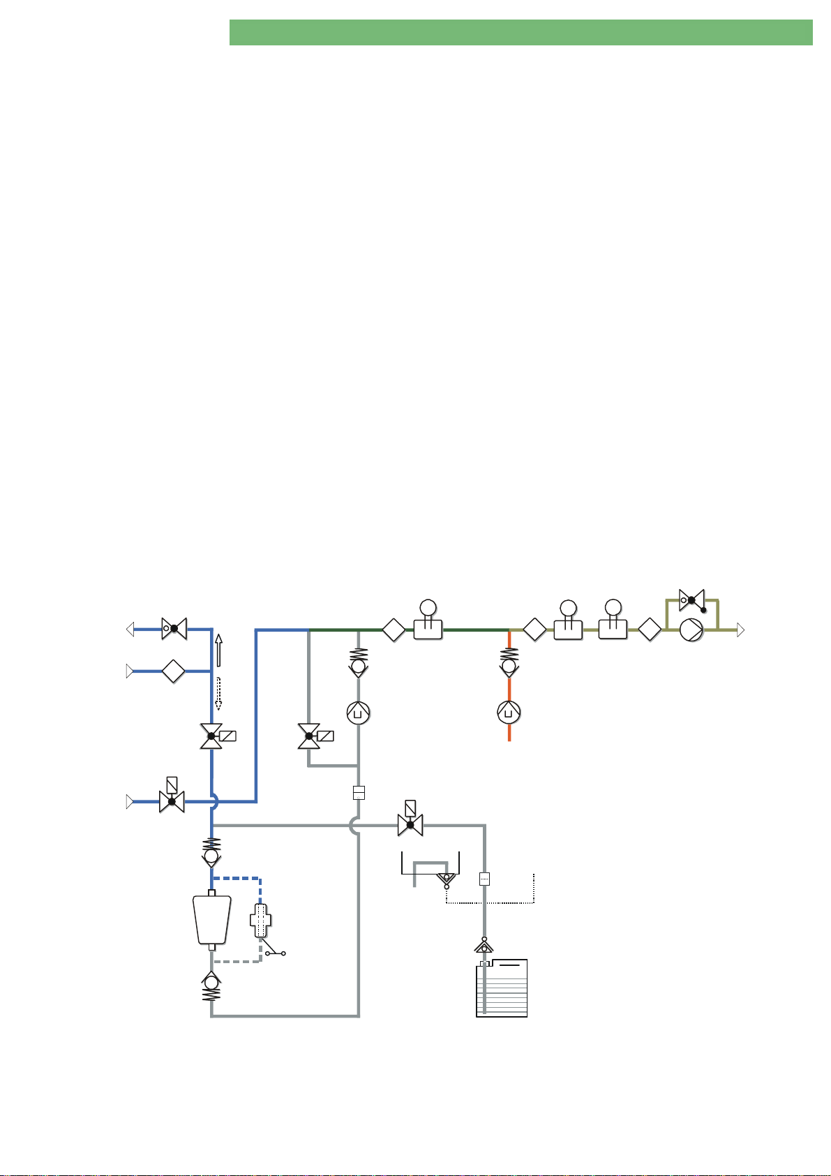
Dialog
+
SW 9.xx
2. Technical System Description 1/2010 2 - 32
2.20.4 Central Bicarbonate and
Concentrate Supply (Option)
2.20.5 BIC Cartridge Holder (Option)
DBK
DBK Throttle Bicarbonate Cartridge Holder
DBKDBK
VBKO
VBKO Bicarbonate Cartridge Holder Top Valve
VBKOVBKO
VBKS
VBKS Bicarbonate Cartridge Holder Concentrate Rod Valve
VBKSVBKS
VBICP
VBICP Bicarbonate Pump Valve
VBICPVBICP
VVB
VVB Upline Tank Valve
VVBVVB
A canister or central supply can be selected via the bicarbonate and
concentrate supply connection BVA and KVA.
The flow pump FPE guarantees a continuous control of the desired dialysate
flow into the balance chambers.
The flow rate is determined by the filling time of the balance chamber. The flow
pump FPE is controlled via the predetermined volume of the chamber and a
continuous detection of the posi tio n o f the membr ane.
Throttle Bicarbonate Cartridge Holder
Throttle Bicarbonate Cartridge HolderThrottle Bicarbonate Cartridge Holder
DBK ensures a constant pressure (approx. 300 mmHg) during the filling of the
bicarbonate cartridge.
Bicarbonate Cartridge Holder Top Valve
Bicarbonate Cartridge Holder Top ValveBicarbonate Cartridge Holder Top Valve
The bicarbonate cartridge is filled to the limit pressure (300 mmHg) after VBKO
opens.
Bicarbonate Cartridge Holder Concentrate Rod Valve
Bicarbonate Cartridge Holder Concentrate Rod ValveBicarbonate Cartridge Holder Concentrate Rod Valve
The bicarbonate cartridge is vented during preparation and in therapy, i.e. VBKO
closes and VBKS opens for a short time. This is repeated in regular intervals
during therapy. VBKS is opened after the end of the therapy to empty the
bicarbonate cartridge.
Bicarbonate Pump Valve
Bicarbonate Pump ValveBicarbonate Pump Valve
VBICP opens shortly after the BIC cartridge was filled, to rinse away the initial
bicarbonate. VBICP switches the BIC pump in bypass after the end of the
therapy to empty the bicarbonate cartridge.
Upline Tank Valve
Upline Tank ValveUpline Tank Valve
VVB cuts off the main flow after the end of the therapy to empty the
bicarbonate cartridge via FPE (VBICP and VBKS are opened).
RVFPE
DBK*
T
TSE
VBKO*
VVB*
RVBO*
RVBU
VBICP*
SPA
BKUS
RVB
FBIC
BICP
BVA
T
VBKS
TSD TSD-S
T T
BICLFTSBIC
RVK
KP
BE
FB
BE
ENDLF-SENDLF
8
FPE
Fig. : BIC Cartridge Holder (Option)
BA-TE-DE08C M.KAY
Dialog+ SW 9xx_sm_C ha pter 2_1-2010.doc/pdf < 100329> yymmdd
B. Braun Avitum AG
Page 46

Dialog
+
SW 9.xx
2. Technical System Description 1/2010 2 - 33
2.20.6 Balance Chamber System
The balance chamber system has the following components:
Balance Chamber BK1
•
BK1
BK1BK1
2.20.7 Working Principle Balance
Chamber System
Phase 1:
Balance Chamber BK2
•
Balance Chamber Dialyser Inlet Valve VDEBK1
•
Balance Chamber Inlet Valve VEBK1
•
Balance Chamber Memb r ane Position Sensor MSBK1
•
Balance Chamber Dialyser Outlet Valve VDABK1
•
Balance Chamber Outlet Valve VABK1
•
The measurement and control of the ultrafiltration rate is accomplished by the
double balance chamber system and the ultrafiltration pump UFP.
Both balance chambers BK1 and BK2 are identical. The chambers have flexible
membranes, which can be moved to both sides. The membranes divide the
chambers into two sub-compartments. The flow direction is defined by the
membranes and the eight solenoid valves. The position of the membranes is
measured by inductive membrane position sensors MSBK1 and MSBK2. The
membrane position sensors (ferrites) are connected to the membranes and each
move in a respective coil MSBK1 and MSBK2.
The balance chamber BK1 is filled with dialysate at the beginning of ph ase 1.
The membrane is in right position. The valves VDEBK1 and VDABK1 are opened.
The balance chamber BK1 is filled by the outlet flow pump FPA with used
dialysate, via valve VDABK1. Simult an e o u s l y t h e fre s h d i alys at e is removed from
the balance chamber BK1 via valve VDEBK1. Phase 1 is completed and the
membrane is in left position (see figure).
BK2
BK2BK2
VDEBK1 and VDEBK2
VDEBK1VDEBK1
VEBK1 and VEBK2
VEBK1VEBK1
VABK1 and VABK2
VABK1VABK1
VEBK2
VEBK2VEBK2
VDABK1 and VDABK2
VDABK1VDABK1
VABK2
VABK2VABK2
VDEBK2
VDEBK2VDEBK2
MSBK1 and MSBK2
MSBK1MSBK1
MSBK2
MSBK2MSBK2
VDABK2
VDABK2VDABK2
8
FPE
VZ
Fig. : Phase 1 Balance Chamber
VDEBK1
VEBK1
VDEBK2
VEBK2
MSBK1
MSBK2
The balance chamber BK2 is filled with fresh dialysate during this period. The
used dialysate from the previous phase 2 is drained (see description phase 2).
BK1
DDE
VABK1
VBP
VDE
VDABK1
VABK2
VLA
LAFS
BL
VDABK2
FBK2
PDA
8
BK2
UFP
FPA
RVFPA
LA
VDA
open
closed
BA-TE-DE08C M.KAY
Dialog+ SW 9xx_sm_C ha pter 2_1-2010.doc/pdf < 100329> yymmdd
B. Braun Avitum AG
Page 47
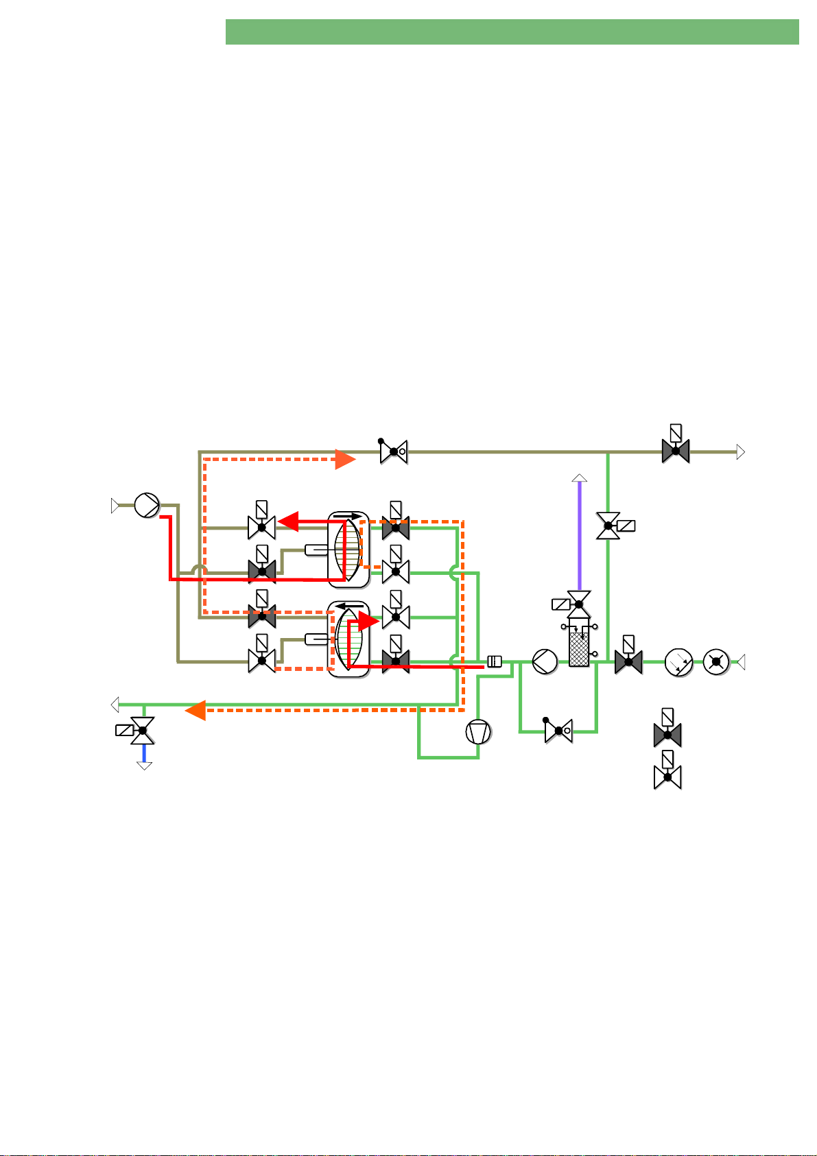
Dialog
+
SW 9.xx
2. Technical System Description 1/2010 2 - 34
After phase 1 is completed there is an automatic switch to the filled balance
Phase 2:
chamber BK2 to obt ain a constant flow in the dialyse r. The complete cycle is
repeated in phase 2, i.e. valves VDEBK2 and VDABK2 are opened. The balance
chamber BK2 is filled via valve VDABK2. Simultaneously the dialysate is drained
from the balance chamber BK2 via valve VDEBK2. Phase 2 is completed and the
membrane is in left position (see figure).
Simultaneously the balance chamber BK1 is filled with fresh dialysate.
Therefore valve VEBK1 is opened. Valve VABK1 is also opened, to initiate the
flow path for the used dialysate to the drain. The membrane moves to the right
position.
The outlet fluid volume is equal to the returned fluid volume, due to the closed
balance chamber system
The fluid volume removed from the closed system via the ultrafiltration pump
UFP is replaced from the blood in the dialyser and equals the precise
ultrafiltration v o l ume.
The system is initialised in preparation, i.e. the membrane sensors are
automatically calibrated and the speed of the flow pumps FPE and FPA are
determined. Thus a synchronisation of the membranes is guaranteed, and the
pump speeds for the desired flow are determined.
8
FPE
VZ
Fig. : Phase 2 Balance Chamber
VDEBK1
VEBK1
VDEBK2
VEBK2
MSBK1
MSBK2
BK1
BK2
DDE
VABK1
VDABK1
VABK2
VDABK2
UFP
FBK2
VLA
LAFS
8
FPA
RVFPA
LA
VBP
VDA
VDE
BL
PDA
open
closed
BA-TE-DE08C M.KAY
Dialog+ SW 9xx_sm_C ha pter 2_1-2010.doc/pdf < 100329> yymmdd
B. Braun Avitum AG
Page 48

Dialog
+
SW 9.xx
2. Technical System Description 1/2010 2 - 35
2.20.8 Ultrafiltration and Rinsing Bridge
The main flow path and bypass have the following components:
Dialyser Inlet Throttle DDE
•
Dialyser Inlet Valve VDE
•
Dialyser Outlet Valve VDA
•
Bypass Valve VBP
•
Outlet Flow Pump FPA
•
The flow path for the main flow and bypass are determined by the valves VDE,
VDA and VBP. The built up flow from the flow pump FPA is stabilised by the
throttle DDE. Valves VDE and VBP are closed for sequential therapy
(ultrafiltration without dialysate flu id flow). The ultrafiltrate removal is carried
out by the ultrafiltration pump UFP.
Further components are:
Red sensitive blood leak detector BL
•
Pressure sensor PDA which monitors the dialysate pressure (also used to
•
calculate TMP)
Air separator LA with built in level sensors LAFS and air separator valve VLA
•
Throttle RVDA functions as a resistance to stabilise the flow of FPE
•
VBP
VBPVBP
VDE
VDEVDE
FPA
FPAFPA
DDE
DDEDDE
VDA
VDAVDA
Detection of Air in Air Separator LA
The throttle RVFPA prevents a high pressure build-up and thus a bursting of
tubing if the flow path is blocked behind FPA. If the set pressure is reached
RVFPA is opened and the fluid can circulate.
If air is detected in the air separator LA by the air separator level sensors LAFS,
the balance chamber switches to free flow:
VEBK1 and VDEBK2 opened
•
VABK1/2 and VDABK1/2 closed
•
VLA is opened and air is removed with positive pressure from LA. VLA is closed
once air is not detected anymore by LAFS. The balance chamber is switched to
normal operation.
BA-TE-DE08C M.KAY
Dialog+ SW 9xx_sm_C ha pter 2_1-2010.doc/pdf < 100329> yymmdd
B. Braun Avitum AG
Page 49

Dialog
+
SW 9.xx
2. Technical System Description 1/2010 2 - 36
2.20.9
DMV
VVBE
EK
VB WT
PE TSH
FEP
VEB
8
EP
Chemical Thermal Disinfection P rogram
Phase 1
Phase 2
H
NSVB
TSHE
T
TSE
WAB
T
A
D
T
BICP
A
T
RVB
B
The position of the couplings is checked by the sensors BICSS, KSS, SBS1 and
SBS2. The machine starts to rinse as soon as the disinfection menu is entered.
After the disinfection type is selected the machine will rinse for 3 minutes and
preheat the system to 45
o
C. During this phase all pumps (EP, FPE, FPA, BICP,
KP, UFP) run and the valves are s witched so that any residual concentrate is
rinsed from the complete hydr aulic circuit.
The air separator LA is filled with water via VLA. The upline tank VB is emptied,
until the bottom NSVB is on, which switches off the heater H (VVBE is closed).
RVFPE
TSD
T
RVK
D
C
KP
BVA
BE
TSD-S
ENDLFBICLFTSBIC
RVDA
BIC
SS
FPE
VZ
SKKSSKBS
KSS
FKFB
T
ENDLF-S
VDEBK1
8
FBK1
VEBK1
MSBK1
VDEBK2
VEBK2
MSBK2
KVA
KE
DDE
BK1
VABK1
VDABK1
VABK2
VDABK2
BK2
RVUFP
VLA
LAFS
FBK2
8
FPA
B
C
RVFPA
UFP
T
VDETSDE
VBP
BL
PDA
LA
VDA
SBS1
M
VD
LVD
SBS2
PEV*
V.D.
FVD
SB1
SB2
A
V
Z.D.
Fig. : Phase 2
BE
KSB KSK
KE
FD
BA-TE-DE08C M.KAY
Dialog+ SW 9xx_sm_C ha pter 2_1-2010.doc/pdf < 100329> yymmdd
B. Braun Avitum AG
Page 50

Dialog
+
SW 9.xx
2. Technical System Description 1/2010 2 - 37
DMV
VVBE
EK
VB WT
PE TSH
A
D
TSHE
FEP
VEB
8
EP
Phase 3
With UFP running, a negative pressure of –100 mmHg is created at PDA. When
this pressure is reached VD opens. The disinfectant is sucked into the hydraulic
system by the UFP via the dialyser connector s. The circulation valve VZ is open
and fluid flows into the upline tank of the water block WAB, because the
throttle RVDA acts as a fo rward resistance. As soon as the co rrect volume is
reached, the upline tank VB is filled up with fresh water (VVBE is controlled by
NSVB).
RVFPE
H
NSVB
T
TSE
WAB
T
T
BICP
A
T
RVB
B
BVA
TSD
T
RVK
D
C
KP
BE
TSD-S
T
ENDLF-S
ENDLFBICLFTSBIC
RVDA
VZ
SKKSSKBS
BIC
SS
KSS
FKFB
VDEBK1
8
FPE
FBK1
VEBK1
MSBK1
VDEBK2
VEBK2
MSBK2
KVA
KE
DDE
BK1
VABK1
VDABK1
VABK2
VDABK2
BK2
RVUFP
VLA
LAFS
FBK2
8
FPA
B
C
RVFPA
UFP
T
VDETSDE
VBP
BL
PDA
LA
VDA
SBS1
M
VD
LVD
SBS2
PEV*
V.D.
FVD
SB1
SB2
A
V
Z.D.
Fig. : Phase 3
Phase 4
Phase 5
Phase 6
BE
KSB KSK
The machine starts to recirculate the fluid, heating the system up to the desired
temperature (e.g. 83
KE
FD
o
C). Once this temperature is reached and a desired
conductivity is re a ched (e.g. 2.2 mS/cm) the disinfec ti o n timer starts.
The machine recirculates the fluid, monitoring the temperature and
conductivity until the disinfection time is reached. There is no flow of fluid to
the drain during suction, heat-up and circulation. Then the machine starts with
the VBICP test. The machine checks whether VVB and VBICP open and close
properly. During the first step of this test VVB and VBICP are closed. With FPE
and FPA still running this causes a negative pressure at PDA. VBICP then opens,
causing a rapid increase in pressure at PDA.
The machine then starts to rinse with VZ closed until the rinsing time is
reached, and the temperature has decreased below 40
o
C and conductivity is
below 0.1 mS/cm. Then the machine gives a message that asks the user to
confirm that the machine is free of disinfectant and the disinfection is
completed.
BA-TE-DE08C M.KAY
Dialog+ SW 9xx_sm_C ha pter 2_1-2010.doc/pdf < 100329> yymmdd
B. Braun Avitum AG
Page 51

+
Dialog
SW 9.xx
2.21 Block Diagram
Touch Controller
Board TCB
2. Technical System Description 1/2010 2 - 38
Communication
Backlight In verte r
Touch Screen
Optical Status
Display Board
OSDB
LC Display
Board BIB
Optical Status
Display Board
OSDB
+
-
Service USB Stick
DCI*
Compact Flash
ABPM *
BSL *
DCI *
COM4 LCD Port
COM3
COM1
Top Level Controller
(Motherboard)
COM2
Parallel
TLC
Port
Speaker
IDE
USB1
USB2
USB3
USB
4-8
Ethernet
DIABUS
Front Panel Board
BICPOS TSHE
KPPOS
UFPOS
BKUS*
SBS1
SBS2
BPA_IMP
BPA_DIR
BPV_IMP
BPV_DIR
SUP
Sensors
Controller
Sensors
Controller/SUP
NSVB
BICSS
MSBK1
MSBK2
RDV
Sensors
BPADS TSD-S
BPVDS ENDLF-S
Seria l B US
KSS PBS
SAD
AB
Analog
Sensors
Board
Controller
(LLA)
SUP
Sensors
TSBIC
TSDE
Sensors
BICLF
Controller
ENDLF
LAFS
BPA
BPV
EP
FPA
BLD
Controller/SUP
Sensors
FPE
START
STOP
Card Reader*
Kt/V-UV*
Crit-Line*
Card
SUPBUS
TSE
TSD
PE
PBE
PA
PV
PDA
FPB
Top Leve l
Low Level
Basic Boa rd
BICP
KP
UFP
LRP
Mains
Voltage
Fig. : Block Diagram
PBM
Power
Board
Motors
Mains Switch
PBV
Power Board
Valves
VZ
SAKV
SMPS-MC
Switch Mode Power Supply
Microcontroller
VDEBK1VVBE
VDEBK2VEB
VDABK1VLA
VDABK2VDE
VEBK1VDA
VEBK2VBP
VABK1VVB*
VABK2VBICP*
VBTVBKS*
VPVVBKO*
VPEVD
VPU
VPD
SAKA
VPA
Heparin Pump
Compact
HOB
* HDF
Online
Board
* Battery
HP
LS
KRALO
KOLB
VSAA
VBE
VDFF
VSAE
VSB
PSAUS
PSABFS
FEDFFS
FEHDFS
* Options
BA-TE-DE08C M.KAY
Dialog+ SW 9xx_sm_C ha pter 2_1-2010.doc/pdf < 100329> yymmdd
B. Braun Avitum AG
Page 52

Dialog
+
SW 9.xx
2. Technical System Description 1/2010 2 - 39
2.21.1 Legend Block Diagram
Digital Board DB
Supervisor
Controller/Supervisor
BPA
BPV
EP
FPA
FPE
BICPOS
KPPOS
UPPOS
BKUS
SBS1
SBS2
BPA_IMP
BPA_DIR
BPV_IMP
BPV_DIR
Arterial Blood Pump
Venous Blood Pump
Degassing Pump
Outlet Flow Pump
Inlet Flow Pump
Bicarbonate Pump Position Sensor
Concentrate Pump Position Se nsor
UF Pump Position Sensor
Bottom Bicarbonate Cartridge Sensor
Rinsing Bridge Connector Sensor 1
Rinsing Bridge Connector Sensor 2
Arterial Blood Pump Motor Hall Sensor
Arterial Blood Pump Direction
Venous Blood Pump Motor Hall Sensor
Venous Blood Pump Direction
Analog Board AB
Controller
NSVB
BICSS
KSS
MSBK1
MSBK2
RDV
SAD
BPADS
BPVDS
Controller
PBS
TSHE
TSE
TSBIC
TSD
TSDE
BICLF
ENDLF
PE
LAFS
Level Sensor Upline Tank
Bicarbonate Rinsing Connec ti o n Se nsor
Concentrate Rinsing Connector S enso r
Membrane Position Sensor Balance Chamber 1
Membrane Position Sensor Balance Chamber 2
Venous Red Detector
Safety Air Detector
Arterial Blood Pump Cover Switch
Venous Blood Pump Cover Switch
Pressure Single Needle
Heater Inlet Temperature Sensor
Degassing Temperature Sensor
Bicarbonate Temperature Sensor
Dialysate Temperature Sensor
Dialyser Inlet Temperature Sensor
Bicarbonate Conductivity
END Conductivity
Degassing Pressure Sensor
Air Separator Level Sensors
BA-TE-DE08C M.KAY
Supervisor
TSD-S
ENDLF-S
Dialog+ SW 9xx_sm_C ha pter 2_1-2010.doc/pdf < 100329> yymmdd
Dialysate Temperature Sensor Supervisor
END Conductivity Supervisor
B. Braun Avitum AG
Page 53

+
Dialog
SW 9.xx
Controller/Supervisor
Power Board Motors PBM
Power Board Valves PBV
2. Technical System Description 1/2010 2 - 40
BLD
PBE
PA
PV
PDA
BICP
KP
UFP
LRP
VVBE
VEB
VLA
VDE
VDA
VBP
VVB
VBICP
VBKS
VBKO
VD
VZ
VDEBK1
VDEBK2
VDABK1
VDABK2
VEBK1
VEBK2
VABK1
VABK2
VBT
VPV
VPE
VPU
VPD
VPA
SAKV
SAKA
Blood Leak Detector
Pressure Sensor
Arterial Pressure Sensor
Venous Pressure Sensor
Pressure Sensor Dialysate Outlet
Bicarbonate Pump
Concentrate Pump
Ultrafiltration Pump
Level Regulation Pump
Upline Tank Inlet Valve
Degassing Bypass Valve
Air Separator Valve
Dialyser Inlet Valve
Dialyser Outlet Valve
Bypass Valve
Upline Tank Valve
BIC Pump Valve
BIC Concentrate Suction Rod Valve
Top BIC Cartridge Valve
Disinfection Valve
Circulation Valve
Dialyser Inlet Valve Balance Chamber 1
Dialyser Inlet Valve Balance Chamber 2
Dialyser Outlet Valve Balance Chamber 1
Dialyser Outlet Valve Balance Chamber 2
Inlet Valve Balance Chamber 1
Inlet Valve Balance Chamber 2
Outlet Valve Balance Chamber 1
Outlet Valve Balance Chamber 2
Blood Side Test Pressure Sensor Valve
Venous Pressure Sensor Val v e
Inlet Pressure Sensor Valve
Up Pressure Sensor Valve
Down Pressure Sensor Valve
Arterial Pressure Sensor Valve
Venous Tubing Clamp
Arterial Tubing Clamp
Heparin Pump Compact
BA-TE-DE08C M.KAY
Dialog+ SW 9xx_sm_C ha pter 2_1-2010.doc/pdf < 100329> yymmdd
HP
LS
KRALO
KOLB
Heparin Pump Compact
Light Barrier Speed Monitoring
Interlocking Sensor
Syringe Plunger Sensor
B. Braun Avitum AG
Page 54

+
Dialog
SW 9.xx
HDF Online Board HOB
2. Technical System Description 1/2010 2 - 41
VSAA
VBE
VDFF
VSAE
VSB
PSAUS
PSABFS
FEDFFS
FEHDFS
Substitution Connection Outlet Valve (drain)
Filter Vent Valve
DF Filter Valve
Substitution Connection Inlet Valve
Substitution Bypass Valve
Port Substitution Outlet Sensor
Port Substitution Drain Sensor
DF Filter Detection Sensor
HD Filter Detection Sensor
BA-TE-DE08C M.KAY
Dialog+ SW 9xx_sm_C ha pter 2_1-2010.doc/pdf < 100329> yymmdd
B. Braun Avitum AG
Page 55

Dialog
+
SW 9.xx
2. Technical System Description 1/2010 2 - 42
2.22 Switch Mode Power Supply Microcontroller SMPS-MC
2.22.1 Block Diagram SMPS-MC
+5VD
+5VD
+5VD
+5VD
+12VD
+12VA
-12VD
+12VD
-12VA
F301
F302
- Ext. - P14- - Motherboard
F303
F304
- ABPM - P7
- DSI - P8
K4
DC
0V
K3
20..30Vdc
DC
PFC
Power
Factor
Correction
F_bat
(Option)
Battery 24V
0V
0V
0V
0V
0V
GND
Forward Converter
I_bat
Secondary SidePrimary Side
1
20
Signals
Microcontroller
Buzzer
Hardware
Watchdog
(EMC)
Filter
F2
F1
T6.25A
L
Fig. : Block Diagram Switch Mode Power Supply Microcontroller SMPS-MC
BA-TE-DE08C M.KAY
Dialog+ SW 9xx_sm_C ha pter 2_1-2010.doc/pdf < 100329> yymmdd
T6.25A
F5B
PE
N
Mains
PE
LH2
Double-
F6
F12A (230V)
F5A/F5B
T6.25A (230V)
F5A
Stage
F20A (110V)
F12A ( 110V)
F6
PE1
N1
LH1
Heater
B. Braun Avitum AG
Page 56

Dialog
+
SW 9.xx
2. Technical System Description 1/2010 2 - 43
2.22.2 System Integration SMPS-MC
/PERSR_N
/AKKU_OK
PF
D24OK
+5VD
+12VD
-12VD
-12VAN
+12VAN
24VL
24VGB
24VGD
B24O K
PGD
+5VG
Power
Battery Option
Mains Switch
Fan
24 V ControlHardware
P9
Battery
F
Low Voltage Differential
Sig nal Adapter
TLC
P3
Secondary Side
24V
Watchdog
Micro-
Power
(Motherboard)
LVDS
Top Level Contr olle r
T1
Messages Output
P2
Machine MonitoringServie Ju mper
P2
5 V
2 x 1F
Control for Battery, Buzzer, Clock
Controlle r
Buzzer
Aux. Voltage
DGND
/B24OFF
WD_S
AKKU_EN
D24OFF
/REM
AKAL_S
AKAL
X101
Watchdog
T4
ail
PF
Primary Side
U Contro l
max
Ua
SMPS-MC
N1
Microcontroller
Heater Control Input
P2
DGND
Switch Mode Power Supply
Heater
/H_PROG
H_DCLK
H_DIN
Hea t er
PE1
LH1
o
LH2
3 x 152 C
Thermal Fuses
900 W
900 W
TCB
Touch Controller Board
TFT D i splay
BIB
Inverter
Backlight
Board
FPB
Front Panel Board
Mains Input
X1
Charge LED
L
N
PE
PE
Fig. : System Integration
BA-TE-DE08C M.KAY
Dialog+ SW 9xx_sm_C ha pter 2_1-2010.doc/pdf < 100329> yymmdd
Centra l Earth
B. Braun Avitum AG
Page 57

Dialog
+
SW 9.xx
2. Technical System Description 1/2010 2 - 44
2.22.3 Component Layout SMPS-MC
C19
: P6
: P5
X1.8
X1.3
X1.2
X1.1
X1.4
PE1LH1 LH2 L N PE P E
X1.5
N1
X1.7
X1.6
F2
F1
F6
F5A
C18
F5B
: P10
: P8
: P5
: P5
: P5
: P4
: P4
: P4
F1 T6.25A 6.3x32 (X1.1: L)
F2 T6.25A 6.3x32 (X1.2: N)
F5A 110/120V: F12A 6.3x32 (X1.6: HZG1-L)
F401
H401
P12
ontroller works correctly
LED H900 Operating Status
230V: T6.25A 6.3x32 (X1.6: HZG1-L)
F5B 110/120V: F12A 6.3x32 (X1.7: HZG2-L)
230V: T6.25A 6.3x32 (X1.7: HZG2-L)
F6 110/120V: F20A 6.3x32 (X1.5: HZG-N)
230V: F12A 6.3x32 (X1.5: HZG-N)
F301 T3.15A TR5 (+5VD1)
F302 T5.0A TR5 (+5VD2)
F303 T3.15A TR5 (+5VD3)
F304 T3.15A TR5 (+5VD4)
F401 T3.15A TR5 (+12VD1)
F402 T5.00A TR5 (+12VD2)
F403 T1.25A TR5 (+12VA)
F60 0 M1 0.0 0A 6.3x32 (+24VL)
F601 T3.15A TR5 (+24VGB)
F602 T3.15A TR5 (+24VGD)
X101 Service Jumper
+
H600H403
H104
-
F303
H303
H300
F301
F302
F304
H301
H302
H304
P10
H601
F601
K3
F602
H602
P4
H402
F600
F402
F403
P5
X103 /EN_EXT
K4
GNDAKKU
XP3.2
X104 Charge Current Battery Option
(left:100%/default: right:50%)
LED off Microcontroller does not work
LED flashes Microcontroller has detected
LED flashes with Microc
approx. 2 Hz
with 5 .. 10 Hz an error
Fan
X100
-
X903
Goldcap
1F Capacitor
Status
LED Operating
Service
Jumper
-
C114
+
C115
+
X104
H900
P7 P8
P11
X101
+24VAKKU
P9
P6
XP3.1
X103
P14
D900
P2
Options
Fig. : Layout SMPS-MC
BA-TE-DE08C M.KAY
+24 VL
Voltages
Motherboard
Dialog+ SW 9xx_sm_C ha pter 2_1-2010.doc/pdf < 100329> yymmdd
Voltages
+24 VGB
+24 VGD
+5 VD2
Voltages
+12 VD1/2
Battery
+12 VA
Battery
/EN_EXT
Option DSI
Charge Current
Option ABPM
Mains Switch/Fan
EXT_ON
Signals
Supervisor)
(Controller/
Digital Board
from Low Level to
Power Supply Control
B. Braun Avitum AG
Page 58

Dialog
+
SW 9.xx
2. Technical System Description 1/2010 2 - 45
2.22.4 Wiring Diagram SMPS-MC with Battery
Option
TFT Display
J1
(right)
J1
F401
P4
H401
H303
H301
H302
H304
H601
H602
H402
F303
F301
F302
F304
F601
F602
F402
F403
P12
P10
Battery
2 x 12V
P5
=blue
-
=brown
+
Pin 1/2
Charge LE D
Fig. : Wiring Diagram SMPS-MC with Battery Option
XP3.2
XP3.1
X103
GNDAKKU
+24VAKKU
P6
P2
P14
X903
P9
X101
X104
P7 P8
P11
H900
J5J3
H104
-
+
H300
K3
Switch Mode Power Supply
F600
K4
C1 15
+
C1 14
+
H600H403
-
-
X100
Microcontroller
J7
Charge LED
SMPS-MC
F5B
F5A
J1
(left)
J9
F2
F1
F6
X1.3
X1.1
X1.7
X1.6
X1.2
X1.5
X1.4
X1.8
BA-TE-DE08C M.KAY
2 x 12 V, 7 Ah
Battery
Fuse for Battery
10 AT (5x20), breaking c apacity 1500 A, 150 Vdc
Jumper X104 Charge Current for Batteries
Default: 50 % (right posi ti o n)
Dialog+ SW 9xx_sm_C ha pter 2_1-2010.doc/pdf < 100329> yymmdd
B. Braun Avitum AG
Page 59

Dialog
+
SW 9.xx
2. Technical System Description 1/2010 2 - 46
2.22.5 Description SMPS-MC
The switch mode power supply microcontroller SMPS-MC is used in Dialog+
machines with software ≥ 9.xx.
Basic Components SMPS-MC
SMPS-MC
Mains input, filter (EMC)
•
Bridge rectifier
•
PFC converter
•
DC/DC converter
•
Transformer
•
24 VL output (protected via F 600)
•
24 VGB output (switched via K 3, p r otected via F601)
•
24 VGD output (switched via K 4, pr o tec ted v i a F602)
•
DC/DC converter 24 V/+5 V (pro tec ted v i a F301/F302/F303/F304)
•
DC/DC converter 24 V/+12 V (pro tec ted v i a F401/F402/F403)
•
DC/DC converter 24 V/-12 V (electro ni c ally protected and via sol d er ed f use
•
F500)
Heater power circuit tri a c V 29/V 30
•
Microcontroller ( D 900) for monitoring and heater c o ntr o l
•
Signal interface P2
•
Power connectors to the system components P4 ... P12
•
Battery screw terminal to 24 V P3
•
The SMPS-MC (Switch Mode Power Supply MicroController) is assembled in
the rear door. The primary triggered switch mode power supply generates the
following voltages on the secondary side: +5 V (5 V = 5 .2 V); ±12 V and 24 V
(24 V = 21.5 ... 29.07 V). The primary side has a wide range input for
120/230/240 V ± 10 %.
The SMPS-MC is not backwards compatible to the switch mode power supply
SMPS.
Battery Option
Mains Volta ge
Mains Switch ON/OFF
Voltages
The battery option is available in the machine ex works and can also be
retrofitted. The blood side functions in therapy can be maintained with a
battery supply (option) in case of a power failure. The charging circuit is
integrated in the SMPS-MC and includes a deep discharge protection.
120/230/240 V ± 10 %, 50/60 Hz
If the Dialog+ is switched off via the
the machine is in standby mode, e.g. the Dialog+ can be switched on and off
via the disinfection program.
The Dialog+ is only disconnected from mains if the mains plug is pu lled out of
the mains receptacle.
Switch-off in Therapy
The buzzer is activated three times if the Dialog+ is switched off in therapy.
Mains Failure
The Dialog+ (with SMPS-MC) can be switched off and on again in battery
operation approx. 16 min after mains failure.
+5 VC Controller power supply
+5 VD: Digital
+5 VG: buffered (generated from +12 VH)
+12 VH: Aux. voltage
12 VAN: Analog
±
12 VD: Digital
±
+24 VGB: Switched blood side
+24 VGD: Switched dialysate side
+24 VL: Power (uncontrolled)
GNDAN: GND analog
GNDD: GND digital
GNDH: GND aux. voltage
GNDL: GND power
Automatic Switch-Off
function in therapy,
BA-TE-DE08C M.KAY
Dialog+ SW 9xx_sm_C ha pter 2_1-2010.doc/pdf < 100329> yymmdd
B. Braun Avitum AG
Page 60

Dialog
+
SW 9.xx
2. Technical System Description 1/2010 2 - 47
Double-Stage Heater and
Microcontroller
%
80
60
20
1800W
LLC 40%
%
80
60
4040
20
720W = 720W
1800W
%
80 80
LLC 6 0 %
60
40
20
%
60
40
20
1080W = 180W + 900W
(>900W: H2 = ON)
Hardware Watchdog
(see also LED H900)
LED H900 Operating Status 3 Modes:
Battery Management
+12 V Voltage
H1 H2
900W900W
80%
OFF
H1 H2
900W900W
20%
24 V Outputs
+5 V Voltage
The SMPS-MC controls the double-stage heater H1/H2 (2 x 900 W). The first
heater circuit (heater H1, 900 W) is driven in 2 % steps. The second heater
is switched with max. power (900 W) if 50% of H1 is reached. H1 is then
controlled with half-wave-shapes, generated by the microcontroller
the SMPS-MC.
Example:
Set value of LLC = 40 % (based on 1800 W)
H1 = 80 % (based on 900 W)
•
H2 = switched off permanently
•
Set value of LLC = 60 % (based on 1800 W)
H1 = 20 % (based on 900 W)
•
H2 = switched on permanently
•
The microcontroller converts the predefined heater power from LLC into bit
patterns (1 bit corresponds to a mains voltage half cycle) to control both
heaters.
The hardware watchdog
the microcontroller fails, i.e. the buzzer is activated, the heater and both
voltages +24VGB/+24 VGD are switched off. The staff call is activated if
present.
LED off : Microcontroller is not working
LED flashes with 5 ... 10 Hz: Microcontroller has detected an error
LED flashes with approx. 2 Hz: Microcontroller is working correctly
The 24 V of the main converter suppl ie s the f ol l owi ng circuits:
24 VL via fuse F600
•
24 VGB via fuse F601 and r el ay K3
•
24 VGD via fuse F602 and Rel a y K4
•
The SMPS-MC has a battery management, with the following compo nents:
Screw terminal XP3.1 (+) and XP3.2 (-) for batteries
•
Protection against incorrect polarity
•
Electronic connection
•
Deep discharge protection TES
•
Charging current regulator
•
Battery full detection
•
Shut-down circuit for the battery test
•
Enable signal
•
All output voltages are maintained during a power failure if the signal
AKKU_EN
also present. The battery is charged if mains voltage is present. The charging is
performed via a body diode even without
battery from deep discharge by disconnecting the battery source from the
circuit at a voltage < 22 V ±0.5 V via a MOSFETT switch.
The 5 V DC/DC converter generates the 5 V voltage from the 24 V. The
overvoltage protection circuit (crowbar) is triggered at 5.75 V ± 250 mV. A reset
of the overvoltage protection circuit is possible only by switching the machine
off and on again. The solder ed f use F 300 di sconnects the 24 V in case of a short
circuit in the DC/DC converter.
A DC/DC converter generates the –12 V voltage from the 24 V. The soldered
fuse F500 disconnects the 24 V in case of a short circuit in the DC/DC
converter.
was set prior to the power failure. The secondary auxiliary voltage is
HW-WD
AKKU_EN
switches the SMPS-MC in a safe condition if
AKKU_EN
. A comparator protects the
D900
H2
from
BA-TE-DE08C M.KAY
Dialog+ SW 9xx_sm_C ha pter 2_1-2010.doc/pdf < 100329> yymmdd
B. Braun Avitum AG
Page 61

Dialog
2.22.6 Fuses
+
SW 9.xx
2. Technical System Description 1/2010 2 - 48
Fuse Voltage
F1
F2
F5A
F5B
F6
F301
F302
F303
F304
F401
F402
F403
F600
F601
F602
L
(Mains Input)
N
(Mains Input)
L
(Heater 1, 900 W)
L
(Heater 2, 900 W)
N
(Heater)
+5 VD1 3.15 A (TR5)
+5 VD2
+5 VD3
+5 VD4
+12 VD1
+12 VD2 5 A (TR5)
+12 VD3 1.25 A (TR5)
+24 VL 10 A (6.3 x 32)
+24 VGB 3.15 A (TR5)
+24 VGD 3.15 A (TR5)
Rated Fuse Value
Fuse Type
6.25 A
(6.3 x 32)
6.25 A
(6.3 x 32)
12 A (110/120 V)
6.25 A (230 V)
(6.3 x 32)
12 A (110/120 V)
6.25 A (230 V)
(6.3 x 32)
20 A (110/120 V)
12 A (230 V)
(6.3 x 32)
5 A (TR5)
3.15 A (TR5)
3.15 A (TR5)
3.15 A (TR5)
Connector
X1.1
X1.2
X1.6
X1.7
X1.5
P4/1
P4/4
P6/1
P11/1
P12/1
P14/6
P5/10
P10/1
P10/4
P10/7
P7/1
P8/1
P12/2
X100/1
P5/4
P7/4
P8/4
P9/5
P9/6
P10/10
P10/14
P11/2
P4/7
P5/1
P7/7
P8/7
P12/4
P4/10
P4/13
P5/8
P12/10
P4/11
P4/14
P5/7
P12/13
P4/12
P4/15
P12/14
BA-TE-DE08C M.KAY
Note:
Soldered fuses (e.g. F300 or F500) must not be changed if they are
defective, i.e. the complete SMPS-MC must be exchanged.
Dialog+ SW 9xx_sm_C ha pter 2_1-2010.doc/pdf < 100329> yymmdd
B. Braun Avitum AG
Page 62

Dialog
+
2.22.7 Signals
SW 9.xx
2. Technical System Description 1/2010 2 - 49
AKAL
AKAL_S
AKKU_EN
AKKU_LADEN
/AKKU_OK
B24OFF
B24OK
D24OFF
D24OK
/DIR_ON
/EXT_ON
EXT_STATE
H_DCLK
H_DIN
/H_PROG
/MSWITCH
PERSR_N
/REM
WD_S
Audible alarm (LLC)
Audible alarm (LLS)
Enable battery operation (possible in therapy mode only)
Signal for external LED (on front panel board) – charging of battery
Load status of the battery
+24 VGB ON/OFF (LLS)
+24VGB OK
+24 VGD ON/OFF (LLS)
+24VGD OK
Jumper X101 – is used to switch on the power supply without using the
signal and deactivates the alarms. (The watchdog signal for the function of the
heater (
The machine can be switched on with this signal (see menu
Option
Status for external switch-on possibility (e.g. central disinfection),
simultaneously input and output; the signal is looped through (connector P14/3
= input).
Clock signal for heater data from LLC. The
signal and is generated by the LLC. The
at
H_DIN
0, 1
The
H_DIN
to the microcontroller (data to control the hea ter) .
0
1
Programming mode for heater data. The
signal and is generated by the LLC.
0
1
Mains switch
Staff call from SMPS-MC
Power fail (power failure)
PF
Remote signal of LLC (clock on digital board)
Watchdog LLS
) is still required to drive the heater.)
H_DIN
: external ON).
H_DCLK
H_DCLK
to the microcontroller.
Data clock
signal is an open-collector signal, is generated by the LLC and sent
Half wave of mains voltage: heater switched off
Half wave of mains voltage: heater switched on
/H_PROG
Programming mode
No programming mode
Signal is an open-collector
Signal is used to send the data
signal is an open-collector
/REM
1.26 Battery
2.22.8 Internal Signals
BA-TE-DE08C M.KAY
Dialog+ SW 9xx_sm_C ha pter 2_1-2010.doc/pdf < 100329> yymmdd
/PF
Watchdog
Power fail for the power supply monitoring
A watchdog is integrated to prevent a permanent unintentional drive of the
heater in case of an LLC reset. The watchdog is retriggered by the LLC with
< 2 s. The
the heater for t = 10 s after the switch-on of the switch mode power supply.
The watchdog has no safety function and is therefore not tested before the
therapy starts.
signal is used for triggering. The watchdog prevents a drive of
H_DIN
B. Braun Avitum AG
Page 63

Dialog
+
SW 9.xx
3. Repair Instructions 1/2010 3 - 1
Table of Content s Page
3. Self Test SW 9.xx
3.1 Microprocessor Unit MPU Test from Controller/Supervisor
3.2 Status Self Test in Service Overview
3.2.1 Set-Up Low Level Controller LLC Test Codes 3-7
3.2.2 Set-Up Low Level Supervisor LLS Test Codes 3-7
3.2.3 Example LLC/LLS Test Codes for Blood Leak Detector 3-8
3.2.4 Overview Test Codes 3-8
3.3 Self Tests in Preparation SW 9.XX Switch Mode Power
Supply Microcontroller SMPS-MC
3.3.1 Service Mode (DIR_ON) 3-9
3.3.2 Battery 3-9
3.3.3 EEPROM 3-10
3.3.4 Buzzer Test via LLS 3-10
3.3.5 Alarm System 3-11
3-5
3-5
3-6
3-9
3.3.6 Monitoring of Analog Voltage ±12 V
3.3.7 Blood Leak Detector 3-12
3.3.8 DFS Pressure Test (Table) 3-13
3.3.8.1 DFS Pressure Test 3-16
3.3.8.2 Membrane Movement/Pressure Build-up VDABK 3-17
3.3.8.3 Pressure Reduction VDABK with UFP 3-18
3.3.8.4 VBP Test 3-19
3.3.8.5 VDE/VDA Test 3-20
3.3.8.6 Pressure Build-up VDABK 3-21
3.3.8.7 Pressure Reduction Membrane Test with UFP 3-22
3.3.8.8 Membrane Test 3-23
3.3.8.9 Pressure Build-up VABK 3-24
3.3.8.10 Membrane Movement to Inlet Side 3-25
3.3.8.11 Pressure Reduction VABK with UFP 3-26
3-12
BA-TE-DE08C M.KAY
3.3.8.12 VEBK Test 3-27
3.3.8.13 Pressure Reduction 3-28
3.3.9 Integrity Test HDF Online 3-29
3.3.10 UF Pump 3-31
3.3.11 Conductivity 3-32
Dialog+ SW 9xx_sm_C ha pter 3_1-2010.doc/pdf < 100329> yymmdd
B. Braun Avitum AG
Page 64

Dialog
+
SW 9.xx
3. Repair Instructions 1/2010 3 - 2
3.3.12 Temperature TSD 3-32
3.3.13 SAD Level Test 3-33
3.3.14 SAD Counter Test 3-33
3.3.15 Equality Test for Blood Side Pressure Sensors 3-34
3.3.16 Pressure Test Substitution Line S-Online HDF Online 3-35
3.3.17 Blood Side Pressure Retention Test 3-36
3.3.18 Disinfection Valve VD 3-37
3.4 LX800 Motherboard
3.4.1 IDE Interface LX800 Motherboard 3-39
3.4.2 COM Ports LX800 Motherboard 3-39
3.4.3 USB Ports LX800 Motherboard 3-39
3.4.4 Detection/Boot Sequence from Bootable USB Sticks 3-40
3.4.5 BIOS Settings for LX800 Motherboard 3-41
3.4.5.1 Standard CMOS Features 3-42
3.4.5.2 Advanced BIOS Features 3-42
3.4.5.3 Advanced Chipset Features 3-42
3.4.5.4 Integrated Peripherals 3-43
3.4.5.5 Power Management Setup 3-43
3.4.5.6 PnP/PCI Configuration 3-43
3.4.5.7 PC Health Status 3-44
3.4.5.8 Change Parameters in CMOS Setup 3-44
3-38
3.5 Installation Software 9.xx
3.5.1 Document Customer Specific Default Values 3-46
3.5.2 Installation Software LLC 9.xx and LLS 9.xx with USB Stick 3-47
3.5.3 Installation Software TLC 9.xx with USB Stick 3-49
3.5.4 Boot Machine /Check Version Number 3-53
3.5.5 Select Options 3-53
3.5.6 Enter Customer Specific Default Values 3-53
3.5.7 Enter Specific Parameters 3-54
3.5.8 Self Test 3-55
3.5.9 Test Run 3-55
3.6 Field Service Utilities FSU
3.6.1 FSU Directories and Subdirectories 3-56
3.6.2 Start Field Service Utility FSU 3-57
3.6.3 Set-Up FSU Main Menu 3-58
3-46
3-56
BA-TE-DE08C M.KAY
Dialog+ SW 9xx_sm_C ha pter 3_1-2010.doc/pdf < 100329> yymmdd
B. Braun Avitum AG
Page 65

Dialog
+
SW 9.xx
3. Repair Instructions 1/2010 3 - 3
3.6.3.1 Hardware Keys for FSU 3-59
3.6.4 Set System Version Number 3-60
3.6.5 Set Working Time Counter (WTC) 3-61
3.6.6 Kill Masterboot Record 3-62
3.6.7 Write Utilities 3-64
3.6.7.1 Write Languages 3-64
3.6.7.2 Write Calibration Data 3-66
3.6.7.3 Write System Configuration 3-69
3.6.7.4 Undo Last Written 3-72
3.6.8 USB Stick Self Test 3-73
3.6.9 Card Reader Read/Write Utilities 3-74
3.6.9.1 Select Menu of Card Reader Commands 3-74
3.6.9.2
3.6.9.3 Write Card Image 3-76
3.6.9.4 Read Patient Diskette 3-77
3.6.9.5 Write Patient Diskette to Card 3-78
3.6.9.6 Read Patient Card 3-79
3.6.9.7 Write Patient Card 3-80
3.6.9.8
3.6.10 Read/Get Error Utilities 3-83
3.6.10.1 Read System Configuration 3-83
3.6.10.2 Read Calibration Data 3-85
3.6.10.3 Read All Trends 3-87
3.6.10.4 Read Screenshots 3-89
3.6.10.5 Get Error (ErrorDisk) 3-91
3.6.11 FSU Handling of Errors 3-93
Read Card Image 3-75
Remove All Patient Data 3-81
BA-TE-DE08C M.KAY
3.6.12 Examination of Results 3-93
3.6.13 Troubleshooting USB Stick 3-94
3.6.13.1 Field Service Utility Menu with Failed CRC Check 3-94
3.7 Default Table for SW 9.xx
3.8 Measures after Repair
3.8.1 Repair Matrix 3-103
3.8.2 Tests and Measures to be Executed 3-104
3.8.2.1 Install Software 3-104
3.8.2.2 Check System Configuration, Production Report and Set if
Necessary
Dialog+ SW 9xx_sm_C ha pter 3_1-2010.doc/pdf < 100329> yymmdd
3-95
3-103
3-104
B. Braun Avitum AG
Page 66

Dialog
+
SW 9.xx
3. Repair Instructions 1/2010 3 - 4
3.8.2.3 Self Test 3-105
3.8.2.4 Conductivity Test Run, Temperature Comparison
Measurement
3.8.2.5 Test Run UF Comparison Measurement 3-105
3.8.2.6 Test Run 3-105
3.8.2.7 Electrical Safety Check 3-106
3.8.2.8 Perform Disinfection after Repair 3-106
3.8.2.9 Document the Executed Activities 3-106
3.8.3 Execution Protocol 3-107
3-105
BA-TE-DE08C M.KAY
Dialog+ SW 9xx_sm_C ha pter 3_1-2010.doc/pdf < 100329> yymmdd
B. Braun Avitum AG
Page 67

Dialog
+
SW 9.xx
3. Repair Instructions 1/2010 3 - 5
3. Self Test SW 9.xx
3.1 Microprocessor Unit MPU Test from
Controller/Supervisor
The microprocessor unit MPU of the controller and supervisor are checked. The
function of the internal MPU registers, flags a nd stac ks is tested.
MPU Test Supervisor
MPU Test Controller
Register Test
Flag Test Set and Reset Capa bility
Stack Test
Reactions in Case of an Error
of the MPU Tes t
The MPU test is performed in therapy mode and service mode after switch-on
prior to the RAM and ROM test.
The MPU test is performed during the boot phase after the RAM and ROM test.
The operating system is not active in this phase.
The following tests are performed:
Read-write capability of the registers
•
Cross-talk between the single bits
•
Address ability of the registers
•
Crosstalk between single words
•
The test checks whet her the flag can be set and reset corre ctly according to
defined conditions.
Query Capability
The test checks whether the correctly set flags can also be evaluated correctly .
The function of the stack is tested by storing and reloading/reading a test
pattern.
Controller
If an error is detected during the MPU te st the TLC
terminates the start procedure – therapy can not
be started. The error message is displayed in the
TSM service program:
Bit 7, BIOS init. error
•
Bit 8, Error in MPU test
•
Supervisor
If an error is detected during the MPU test the
following alarms are displayed:
In Therapy – Therapy Selection:
• Hardware error RAM/ROM (SUP)
In TSM Service Program:
• Error in MPU test
BA-TE-DE08C M.KAY
Dialog+ SW 9xx_sm_C ha pter 3_1-2010.doc/pdf < 100329> yymmdd
B. Braun Avitum AG
Page 68
Dialog
+
SW 9.xx
3. Repair Instructions 1/2010 3 - 6
3.2. Status Self Test in Service
Overview
Display LLC/LLS Test Codes
in Status Self Test
Water Tank
Water Tank
Water TankWater Tank
VVBE: OPENED/CLOSED
NSVB: HIGH/LOW
Degassing
Degassing
DegassingDegassing
EP: XXXX rpm
VEB: OPEN/CLOSED
PE: XXX mmHg
TSE: XX.X oC
TSHE: XX.X oC
Heater
Heater
HeaterHeater
HEATER: XX.X %
Air Separator
Air Separator
Air SeparatorAir Separator
LAFSO: NO AIR/AIR
LAFSU: NO AIR/AIR
VLA: OPEN/CLOSED
Temperature
Temperature
TemperatureTemperature
TSE: XX.X oC
TSBIC: XX.X oC
TSD: XX.X oC
TSD_S: XX.X oC
TSDE: XX.X oC
Conductivity
Conductivity
ConductivityConductivity
BICLF: X.X mS/cm
ENDLF: XX.X mS/cm
ENDLF_S: XX.X mS/cm
BICP: XX rpm
BICP_S: XX rpm
BIC-Ratio: XX.X
BIC-Ratio_S: XX.X
KP: XX rpm
KP_S: XX rpm
END-Ratio: XX.X
END-Ratio_S: XX.X
The test codes for the self test are displayed by LLC and LLS in the
on the first page of the service overview (in therapy).
Test
Balance Chamber
Balance Chamber
Balance ChamberBalance Chamber
MSBK1: XXXXX
MSBK2: XXXXX
VEBK1_S: OPEN/CLOSED
VABK1_S: OPEN/CLOSED
VDEBK2_S: OPEN/CLOSED
VDABK2_S: OPEN/CLOSED
VEBK2_S: OPEN/CLOSED
VABK2_S: OPEN/CLOSED
VDEBK1_S: OPEN/CLOSED
VDABK1_S: OPEN/CLOSED
Flow (Dialysate Fluid)
Flow (Dialysate Fluid)
Flow (Dialysate Fluid)Flow (Dialysate Fluid)
FPE: XXXX rpm
FPA: XXXX rpm
FMD: XXX ml/min
FMD_S XXX ml/min
Valves (Bypass)
Valves (Bypass)
Valves (Bypass)Valves (Bypass)
VBP: OPEN/CLOSED
VBP_S: OPEN/CLOSED
VDE: OPEN/CLOSED
VDE_S: OPEN/CLOSED
VDA: OPEN/CLOSED
VDA_S: OPEN/CLOSED
Valves (
V al v es ( Disinfection)
Valves (Valves (
VZ: OPEN/CLOSED
VD OPEN/CLOSED
VD_S OPEN/CLOSED
BL: X.XX ‰
BL_S: X.XX ‰
Disinfection)
Disinfection)Disinfection)
Blood Leak
Blood Leak
Blood LeakBlood Leak
Ultrafiltration
Ultrafiltration
UltrafiltrationUltrafiltration
UFP: XX rpm
UFP_S: XX rpm
PDA: XXX mmHg
PDA_S: XXX mmHg
TMP: XXX mmHg
BIC Cartridge Holder
BIC Cartridge Holder
BIC Cartridge HolderBIC Cartridge Holder
BKUS: OPEN/CLOSED
BKUS_S: OPEN/CLOSED
VVB: OPEN/CLOSED
VBICP: OPEN/CLOSED
VBKO: OPEN/CLOSED
VBKS: OPEN/CLOSED
Valves Online
Valves Online
Valves OnlineValves Online
VBE: OPEN/CLOSED
VBE_S: OPEN/CLOSED
VDFF: OPEN/CLOSED
VDFF_S: OPEN/CLOSED
VSB: OPEN/CLOSED
VSB_S: OPEN/CLOSED
VSAA: OPEN/CLOSED
VSAA_S: OPEN/CLOSED
VSAE: OPEN/CLOSED
VSAE_S: OPEN/CLOSED
Pump Online
Pump Online
Pump OnlinePump Online
OPS: XXXX rpm
OPS_S: XXXX rpm
Subst. Flow (Online)
Subst. Flow (Online)
Subst. Flow (Online)Subst. Flow (Online)
FMS: XXX ml/min
FMS_S: XXX ml/min
Status Self
Blood Side (Pressure)
Blood Side (Pressure)
Blood Side (Pressure)Blood Side (Pressure)
PA: XXX mmHg
PA_S: XXX mmHg
PBE: XXX mmHg
PV: XXX mmHg
PV_S: XXX mmHg
PBS: XXX mmHg
PBS_S: XXX mmHg
Blood Pumps
Blood Pumps
Blood PumpsBlood Pumps
BPA: XXXX rpm
BPA_S: XXXX rpm
BPV: XXXX rpm
BPV_S: XXXX rpm
Tubing Clamps
Tubing Clamps
Tubing ClampsTubing Clamps
SAKA: OPEN/CLOSED
SAKV: OPEN/CLOSED
SAKV_S: OPEN/CLOSED
Air Detector
Air Detector
Air DetectorAir Detector
SAD: NO AIR/AIR
SAD_S: NO AIR/AIR
SAD TIME_S: OK
SAD REF_S: XXXX mV
SAD VOL: XXXX µl
SAD VOL_S: XXXX µl
Heparin
Heparin
HeparinHeparin
HP: STOP
POSITION: XX.XX mm
Status Self Test
Status Self Test
Status Self TestStatus Self Test
LLC: XXXXX
LLS: XXXXX
LLC/S & TLC Alarm Window LLC Message Window
BA-TE-DE08C M.KAY
Dialog+ SW 9xx_sm_C ha pter 3_1-2010.doc/pdf < 100329> yymmdd
B. Braun Avitum AG
Page 69

Dialog
+
SW 9.xx
3. Repair Instructions 1/2010 3 - 7
3.2.1 Set-Up Low Level Controller
LLC Test Codes
Format of LLC Test Co des:
LLC Test Codes Before the
Test Codes of the Individual Tests
TTSSx:
TT
SS
Examples
11102
33701
37991
Individual Tests
TT 00 x
TT 01 x
TT 02 x
TT 03 x
TT 04 x
TT 05 x
LLC test code to LLS
Performed test step
x
Number of performed repeats
0 ≤ x < repeats until error message
Third blood leak detector test: send signal to blood leak detector task
Second BS pressure test terminated, because during autopriming, e.g. an LF
error occurred.
VD test passed after the second time.
Start test.
Error: timeout (10 s) at "Before Test Start Wait for Test Code 0 from LLS".
Test check prerequisites (if present, see respective tests).
Error: Check timeout test prerequisites (if present, timeout time see respective
tests).
Wait for LLS test code from LLS.
Error: timeout (10 s) at "Before Test Start Wait for LLS Test Code from LLS".
Range 10x .... 99x
Not all test codes are displayed sequentially, due to the implementation.
A higher test code always includes all the finalised subcodes with lower
priority.
In case of an error: The subcode always includes the subpha se where the error
occurred.
3.2.2 Set-Up Low Level Supervisor LLS
Test Codes
Format of LLS Test Co des:
(Value ≥ 10000)
TTSSS
TT
:
SSS
Example:
11104
The test code is displayed as a numer ical value ≥ 10000. If the value is < 9000,
this is the required rinsing volume for the HDFO filter rinsing in ml. If the value
is > 9000 and < 10000, the last three digits displ a y the r e qui r ed HDFO filter
rinsing volume in ml through the valves VSAA and VSAE ( V S B is closed).
LLS test code to LLC
Performed test step
Blood leak detector test: measure level for red and green
BA-TE-DE08C M.KAY
Dialog+ SW 9xx_sm_C ha pter 3_1-2010.doc/pdf < 100329> yymmdd
B. Braun Avitum AG
Page 70

Dialog
+
SW 9.xx
3. Repair Instructions 1/2010 3 - 8
3.2.3 Example LLC/LLS Test Codes
for Blood Leak Detector
LLC Test Code:
11 (TT):
10 (SS):
11102
11004
2 (x):
LLS Test Code:
11 (TT):
004 (SS):
LLC Test
Code
1102x
1.
2.
3.
1110x
4.
1120x Wait for D24O F F (timeout 30 s) 11011
5.
6.
1130x Wait for D24O N (timeout 30 s)
7.
1199x Completed
8.
Prerequisites for Test:
Upline tank must be filled
Timeout 2 min
Test code = 11 to LLS Test code = 11 back to LLC
EV_TESTE_BLUTLECK_EIN to BlutleckTaskID Test initialisation (VGD ON)
LLC Test Steps LLS Test Steps LLS Test
Blood leak detector test
Send signal to blood leak task
Third repetition (x = 0, 1, 2)
Blood leak detector test
Measure level for red and green
Single measurement of green,
Single measurement of red,
then comparison of: red ≥ green + 0.2 V
no timeout
Acknowledge with switch-off of VGD 11005 –
VGD ON 11012
Code
11000 –
11003
11004
3.2.4 Overview Test Codes
00
11
12
15
16
17
20
21
22
25
26
27
28
30
31
32
33
37
40
No tests
Blood leak detector
DFS pressure test
Integrity test HDF online (only for Dialog+ HDF online)
Alarm system
Monitoring of analog voltage ± 12 V
UF pump
End conductivity
Temperature TSD
SMPS-MC EEPROM
SMPS-MC service mode
SMPS-MC battery
SMPS-MC buzzer
SAD: Level test
SAD: Counter test
Pressure sensors blood side: Equality test for blood side pressure sensors
Pressure sensors blood side: Blood side pressure test
Disinfection Valve VD
Pressure test substitution line S-Online HDF online
BA-TE-DE08C M.KAY
Dialog+ SW 9xx_sm_C ha pter 3_1-2010.doc/pdf < 100329> yymmdd
B. Braun Avitum AG
Page 71

Dialog
+
SW 9.xx
3. Repair Instructions 1/2010 3 - 9
3.3 Self Test in Preparation SW 9.xx Switch Mode
Power Supply Microcontroller SMPS-MC
3.3.1 Service Mode (DIR_ON)
Configuration
Test Code
Repeats Until Error Message
ID Error Message
Reaction to the Test Result in Preparation
LLC Test
Code
1.
2.
2610x Switch-off of VGD and VGB 26001
3.
4.
5.
2620x Wait for feedback of test result via BIOS (timeout 15 s)
6.
2630x Set set point of heater to 0
7.
2699x Completed VGD ON
8.
Prerequisites for Test:
Test code = 26 to LLS Test code = 26 back to LLC
Wait for D24OFF and B 24OFF
(Timeout 15 s)
Set set point for heater to self test code #110
LLC Test Steps LLS Test Steps LLS Test
none
3.3.2 Battery
Configuration
Test Code
Repeats Until Error Message
Switch mode power supply microcontroller SMPS-MC with and without battery
26
1
1152:
Power supply service mode - no therapy
Error: X101 connec ted ( /DI R_ON = 0)
• therapy not possible
because alarms deactivated, information text
OK: X101 open (/DIR_O N = 1)
Therapy possible
•
Code
VGB ON
Switch mode power supply microcontroller SMPS-MC with and without battery
27
3
ID Error Message
Reaction to the Test Result in Preparation
LLC Test
Code
1.
2.
2710x Switch-off of VGD and VGB 27001
3.
4.
5.
2720x Wait for feedback of test result via BIOS (timeout 15 s)
6.
2730x Set set point of heater to 0
7.
2799x Completed VGD ON
8.
Prerequisites for Test:
Test code = 27 to LLS Test code = 27 back to LLC
Wait for D24OFF and B 24OFF
(Timeout 15 s)
Set set point for heater to self test code #112
LLC Test Steps LLS Test Steps LLS Test
none
1150:
Selftest error SMPS battery test
Error: Battery not present or not loaded
Information text and
•
therapy possible
OK: Battery present and loaded
Therapy possible
•
VGB ON
Code
BA-TE-DE08C M.KAY
Dialog+ SW 9xx_sm_C ha pter 3_1-2010.doc/pdf < 100329> yymmdd
B. Braun Avitum AG
Page 72

Dialog
+
3.3.3 EEPROM
SW 9.xx
3. Repair Instructions 1/2010 3 - 10
Configuration
Test Code
Repeats Until Error Message
ID Error Message
Reaction to the Test Result in Preparation
LLC Test
Code
1.
2.
2510x Switch-off of VGD and VGB 25001
3.
4.
5.
2520x Wait for feedback of test result via BIOS (timeout 15 s)
6.
2530x Set set point of heater to 0
7.
2599x Completed VGD ON
8.
Prerequisites for Test:
Test code = 25 to LLS Test code = 25 back to LLC
Wait for D24OFF and B 24OFF
(Timeout 15 s)
Set set point for heater to self test code #113
LLC Test Steps LLS Test Steps LLS Test
3.3.4 Buzzer Test via LLS
Configuration
Test Code
Repeats Until Error Message
Switch mode power supply microcontroller SMPS-MC with and without battery
25
1
1154:
SMPS-EEPROM defective
Test is not performed at present
Answer from SMPS-MC is OK because the EEPROM is not used at present
•
Code
VGB ON
Switch mode power supply microcontroller SMPS-MC with and without battery
28
3
ID Error Message
Reaction to the Test Result in Preparation
LLC Test
Code
1.
2.
2810x Switch-off of VGD and VGB 28001
3.
4.
5.
6.
2820x Wait for feedback of test result via BIOS (timeout 15 s)
7.
2830x Set set point of heater to 0
8.
2899x Completed VGD ON
9.
Prerequisites for Test:
Test code = 10 to LLS Test code = 10 back to LLC
Wait for D24OFF and B 24OFF
(Timeout 15 s)
Set set point for heater to self test code #115
LLC Test Steps LLS Test Steps LLS Test
none
1145:
Self test error SMPS buzzer test
Error: buzzer defective
Information text and
•
OK:
Therapy possible
•
Activate buzzer after app ro x. 1 s for 250 ms 28003
VGB ON
therapy possible
Code
BA-TE-DE08C M.KAY
Dialog+ SW 9xx_sm_C ha pter 3_1-2010.doc/pdf < 100329> yymmdd
B. Braun Avitum AG
Page 73

+
Dialog
SW 9.xx
3.3.5 Alarm System
3. Repair Instructions 1/2010 3 - 11
Test Code
Repeats Until Error Message
ID Error Message
Actions after Error
LLC Test
Code
Code LLC LLS Code
1.
2.
3.
1610x
4.
5.
1620x Wait for D24O F F and B24OFF (timeout 60 s since st art
6.
7.
1630x Wait for D24O N and B24ON (timeout 10 s)
8.
1630x
9.
10. 1640x Wait for D24O F F (t i meout 60 s since start of code 200)
11.
12. 1650x Wait for D24O N (timeout 10 s)
13. 1699 Completed
Prerequisites for Test:
No alarm activation
Test code = 16 to LLS Test code = 16 back to LLC
OSD LED OFF, Sound OFF
No alarm activation
Timeout 60 s
of code 100)
D24ON and B24ON:
Alarm activation LLC/TLC
Activation test alarm with sound and OSD LED red (ID
1002)
LLC Test Steps LLS Test Steps LLS Test
16
1
1167:
Sound + LED test failed
None (test is repeated immediately)
Code
Start condition for the test:
1. „OSD-LED OFF“ detected
2. „Sound OFF“ detected
Activation of the red OSD LED
Wait for feedback of the activation and switch-off of
the LED
Wait for LED off
Acknowledge with switch-off of the power supply
trigger, i.e. switch-off of VGD and VGB
Trigger ON 16011
Condition for the test:
1. „OSD LED red left and right ON“ detected
2. „Sound ON“ detected
Acknowledge with switch-off VGD 16022 –
VGD ON 16028
16001
16002
16003
16004
16005 –
16010
16021
16027
BA-TE-DE08C M.KAY
Dialog+ SW 9xx_sm_C ha pter 3_1-2010.doc/pdf < 100329> yymmdd
B. Braun Avitum AG
Page 74
Dialog
+
SW 9.xx
3. Repair Instructions 1/2010 3 - 12
3.3.6 Monitoring of Analog Voltage ±12 V
LLC Test
Code
1.
2.
3.
1710x
4.
5.
1720x
6.
7.
1730x
8.
9.
1740x
10.
1799 Completed
11.
Objective
Test Code
Repeats Until Error Message
ID Error Message
Actions after Error
LLC Test Steps LLS Test Steps LLS Test
Prerequisites for Test:
± 12V voltage in limit range
Test code = 17 to LLS Test code = 17 back to LLC
Failure of voltage check
Timeout 15 s
Voltage check OK
Timeout 15 s
Failure of voltage check
Timeout 15 s
Voltage check OK
Timeout 15 s
Check the monitoring of the analog voltage ±12 V.
17
1
1155:
12 V not passed
±
None (test is repeated immediately)
No test activation 17001 –
Delete test activation for voltage 1:
TEST1 set
Test activation for voltage 2:
TEST2n set
Delete test activation for voltage 2:
TEST2n set
low
low
high
Code
17003
17011 –
17013
17021 –
17023
17031
3.3.7 Blood Leak Detector
Objective
Test Code
Repeats Until Error Message
ID Error Message
Actions after Error
LLC Test
Code
1. 1102x
2. Test code = 11 to LLS Test code = 11 back to LLC
3. 1110x EV_TESTE_BLUTLECK_EIN to Bl ut l eckTaskID Test initial i sat i o n (V GD ON)
4. Acknowl e dge with switch-off o f V GD 11005 –
5. 1120x Wait for D24OFF (timeo ut 30 s) 11011
6. VGD ON 11012
7. 1130x Wait for D24ON (timeo ut 30 s)
8. 1199x Completed
Prerequisites for Test:
Upline tank must be filled
Timeout 2 min
LLC Test Steps LLS Test Steps LLS Test
The switch function between the LEDs and the PWM drive of the LEDs is tested.
11
3
1156:
Blood leak test not OK
Rinse, repeat all tests
11000 –
Single measurement of green,
Single measurement of red,
then comparison of: red ≥ green + 0.2 V
no timeout
11003
11004
Code
BA-TE-DE08C M.KAY
Dialog+ SW 9xx_sm_C ha pter 3_1-2010.doc/pdf < 100329> yymmdd
B. Braun Avitum AG
Page 75

Dialog
+
SW 9.xx
3. Repair Instructions 1/2010 3 - 13
3.3.8 DFS Pressure Test (Table)
Objective
Test Code
Repeats until error message
ID Error Message
Actions after error
LLC Test
Code
1. Prerequisites for Test:
Upline tank must be filled
2.
1.
2.
3.
4.
5.
1220x
1221x
1230x
1235x
1240x
Test code = 12 to LLS Test code = 12 back to LLC
Membrane Movement VDABK
FPE = 1500 ml⋅/min
FPA = 20 ml/min
Valve Status:
VEBK1/2, VDEBK1/2, VABK1/2 --------- opened
VDABK1/2 ----------------------------- closed
VBP, VDA, VDE------------------------ opened
VLA ---------------------- (5 s to vent) opened
Final Condition:
No further drop of the values for the balance
chamber sensors or timeout 60 s
Pressure build-up VDABK
FPE = 1500 ml⋅/min
FPA = 20 ml/min
Valve Status:
VEBK1/2, VDEBK1/2, VABK1/2 ------------opened
VDABK1/2------------------------------ closed
VDE, VDA, VBP------------------------ opened
Final Condition:
PDA ≥ +425 mmHg for 1 s or timeout 60 s
Pressure reduction UFP
FPE = 500 ml/min
FPA = 100 ml/min
Valve Status:
VEBK1/2, VABK1/2 -----------------------opened
VDA B K1 / 2 , V D E B K 1/ 2 ------------------- closed
VDE, VBP ----------------------------- opened
VDA----------------------------------- closed
PDA ≤ +380 mmHg or timeout 60 s
VBP test
FPE = 800 ml/min
FPA = 100 ml⋅/min
Valve Status:
VEBK1/2, VABK1/2, VDEBK1/2 ------------opened
VDABK1/2------------------------------ closed
VDE, VBP ------------------------------ closed
VDA---------------------------------- opened
Test timeout 30 s or wait for inversio n of
LLS_SELFTESTBIT from LLS
VDE/VDA test
FPE = 800 ml/min
FPA = 100 ml/min
Valve Status:
VEBK1/2, VDEBK1/2, VABK1/2 --------- opened
VDABK1/2 ----------------------------- closed
VBP ---------------------------------- opened
VDA, VDE------------------------------ closed
Test timeout 60 s or wait for inversio n of
LLS_SELFTESTBIT from LLS
LLC Test Steps LLS Test Steps LLS Test
Pressure test of the balance system and function test of the valves, drive of UFP for
function test of speed detection.
12
1
1157:
DF pressure test will be repeated
Rinse, repeat all tests.
Code
Wait until VLA is detected as opened 12000
12019
Wait until VLA is detected as closed 12020
12021
Start condition for the test (2,5 s):
1. Correct valve position
2. UFP stopped (UF rate < 500 ml/h)
3. 300 mmHg < PDA < +450 mmHg
Test 5 s,
max. deviation ∆PDA < 25 mmHg,
Acknowledge with inversion of LLS_SELFTESTBIT
Start condition for the test (2,5 s):
1. Correct valve position
2. UFP stopped (UF rate < 500 ml/h)
3. 300 mmHg < PDA < +450 mmHg
Test 5 s,
max. deviation ∆PDA < 25 mmHg,
Acknowledge with inversion of LLS_SELFTESTBIT
12021 –
12026
12027 –
12036
12037
12038
12061 –
12066
12067 –
12076
12077
12078
BA-TE-DE08C M.KAY
Dialog+ SW 9xx_sm_C ha pter 3_1-2010.doc/pdf < 100329> yymmdd
B. Braun Avitum AG
Page 76

Dialog
+
SW 9.xx
3. Repair Instructions 1/2010 3 - 14
6.
7.
8.
9.
10.
11.
1245x
1250x
1255x
1260x
1265x
1270x
VDABK
Pressure build-up
FPE = 500 ml/min
FPA = 100 ml/min
Valve Status:
VEBK1/2, VDEBK1/2, VABK1/2 --------- opened
VDABK1/2 ----------------------------- closed
VBP, VDA, VDE------------------------ opened
PDA ≥ +425
Pressure reduction with UFP
FPE = 800 ml/min
FPA = 20 ml/min
Valve Status:
VEBK1/2, VDABK1/2------------------- opened
VDEBK1/2, VABK1/2-------------------- closed
VBP, VDE ----------------------------- opened
VDA----------------------------------- closed
PDA ≤ +380 mmHg or timeout 60 s
Membrane test
FPE = 800 ml/min
FPA = 20 ml/min
Valve Status:
VEBK1/2, VDABK1/2------------------- opened
VDEBK1/2, VABK1/2-------------------- closed
VBP, VDE, VDA------------------------ opened
Test timeout 60 s or wait for inversio n of
LLS_SELFTESTBIT from LLS
Pressure build-up VABK
FPE = 500 ml/min
FPA = 500 ml/min
Valve Status:
VEBK1/2, VDEBK1/2, VDABK1/2-------- opened
VABK1/2 ------------------------------ closed
VBP, VDA, VDE------------------------ opened
PDA ≥ +425 mmHg for 1 s or timeout 60 s
Membrane movement
FPE = 500 ml/min
FPA = 1500 ml⋅/min
Valve Status:
VEBK1/2, VABK1/2 --------------------- closed
VDEBK1/2, VDABK1/2 ----------------- opened
VBP, VDA, VDE------------------------ opened
Test timeout 60 s or no increase of the values of
the membrane position sensors
Pressure reduction with UFP
FPE = 500 ml/min
FPA = 500 ml/min
Valve Status:
VEBK1/2, VABK1/2 --------------------- closed
VDEBK1/2, VDABK1/2 ----------------- opened
VBP, VDE ----------------------------- opened
VDA----------------------------------- closed
PDA ≤ +380 mmHg or timeout 60 s
VDABK
VDABKVDABK
for 1 s or timeout 60 s
mmHg
Start condition for the test (10 s):
1. Correct valve position
2. UFP stopped (UF rate < 500 ml/h)
3. +300 mmHg < PDA < +450 mmHg
Test 10 s,
max. deviation ∆PDA < 25 mmHg,
Acknowledge with inversion of LLS_SELFTESTBIT
12101
12101
12101 –
12121
12122 –
12131
12132
12133
12151
12151
12151
BA-TE-DE08C M.KAY
Dialog+ SW 9xx_sm_C ha pter 3_1-2010.doc/pdf < 100329> yymmdd
B. Braun Avitum AG
Page 77

Dialog
+
SW 9.xx
3. Repair Instructions 1/2010 3 - 15
1275x
12.
1280x
13.
1299 Completed
14.
VEBK test
FPE = 800 ml/min
FPA = 500 ml/min
Valve Status:
VEBK1/2, VABK1/2 --------------------- closed
VDEBK1/2, VDABK1/2 ----------------- opened
VBP, VDE, VDA------------------------ opened
Test timeout 60 s or wait for inversio n of
LLS_SELFTESTBIT from LLS
Pressure reduction
FPE = 500 ml/min
FPA = 500 ml/min
Valve Status:
VEBK1/2, VDEBK1/2------------------- opened
VABK1/2, VDABK1/2------------------- opened
VBP, VDA, VDE------------------------ opened
Timeout 60 s
Start condition for the test (5 s):
1. Correct valve position
2. UFP stopped (UF rate < 500 ml/h)
3. +300 mmHg < PDA < +450 mmHg
Test 10 s,
max. deviation ∆PDA < 25 mmHg,
Acknowledge with inversion of LLS_SELFTESTBIT
12151 –
12161
12162 –
12181
12182
12183
12000
BA-TE-DE08C M.KAY
Dialog+ SW 9xx_sm_C ha pter 3_1-2010.doc/pdf < 100329> yymmdd
B. Braun Avitum AG
Page 78

+
Dialog
3.3.8.1 DFS Pressure Test
SW 9.xx
3. Repair Instructions 1/2010 3 - 16
General Comments
The closing function of VLA is tested implicitly together with all
tests that generate an overpressure at PDA, because the
overpressure is not built up and not maintained when VLA is open.
Therefore an explicit test of VLA is not required. DFS pressure test:
A controlled membrane movement is performed to the outlet
•
side prior to the phase
The FPE and FPA pumps are set to 1500 ml/min in phases with
•
membrane movement. Thus a fast movement of the membrane
is achieved.
UFP is activated during the pressure build-up phase and thus
•
tested.
The evaluation of the pressure changes in a test interval is
•
performed via the pressure at the end of the test interval. (The
pressure difference to the minimum and maximum sensor
value is created in the test interval.)
VLA is opened for 5 s at the beginning of the test to ensure
•
that the air separator is completely filled with water.
Simultaneously the function for the monitoring of the current
is checked.
Pressure build-up VDABK
.
UFP is started during the pressure build-up phase.
•
The acknowledgement of the single test steps in the DFS
•
pressure test is performed via a bit in the internal
communication (between LLS and LLC).
BA-TE-DE08C M.KAY
Dialog+ SW 9xx_sm_C ha pter 3_1-2010.doc/pdf < 100329> yymmdd
B. Braun Avitum AG
Page 79

Dialog
+
SW 9.xx
3. Repair Instructions 1/2010 3 - 17
3.3.8.2 Membrane Movement/Pressure
Build-up VDABK
VDE
VBP
VDEBK
FPE
VEBK
RVDA
Fig. : Flow Diagram Membrane Movement/Pressure Build-up VDABK
The speed for FPE and FPA are slowly set in increments of 200 min-1 to a
maximum flow of 1500 ml/min and 10 ml/min respectively. The membrane
movement with the resultin g pressure build-up is terminated after no further
drop of the values for the balance chamber sensors is detected. The membrane
is moved to the outlet.
1.
2.
LLC Test
Code
1220x
1221x
Membrane movement VDABK
FPE = 1500 ml/min
FPA = 20 ml/min
Valve Status:
VEBK1/2, VDEBK1/2, VABK1/2 ------------opened
VDABK1/2------------------------------ closed
VDE, VDA, VBP------------------------ opened
VLA ---------------------- open to vent for 5 s
Final Condition:
No further drop of the values for the balance
chamber sensors or timeout 60 s
Pressure build-up VDABK
FPE = 1500 ml⋅/min
FPA = 20 ml/min
Valve Status:
VEBK1/2, VDEBK1/2, VABK1/2 ------------opened
VDABK1/2------------------------------ closed
VDE, VDA, VBP------------------------ opened
Final Condition:
PDA ≥ +425 mmHg for 1 s or timeout 60 s
LLC Test Steps LLS Test Steps LLS Test
VDABK
VABK
FPA
Wait until VLA is detected as opened 12000
Wait until VLA is detected as closed 12020
VDA
UFP
PDA
open
offen
closed
geschlossen
Code
12019
BA-TE-DE08C M.KAY
Dialog+ SW 9xx_sm_C ha pter 3_1-2010.doc/pdf < 100329> yymmdd
B. Braun Avitum AG
Page 80

+
Dialog
3.3.8.3 Pressure Reduction VDABK
SW 9.xx
with UFP
3. Repair Instructions 1/2010 3 - 18
VDE
VBP
VDEBK
FPE
VEBK
RVDA
Fig. : Flow Diagram Pressure Reduction VDABK with UFP
LLC Test
Code
1230x
3.
Pressure reduction UFP
FPE = 500 ml/min
FPA = 100 ml/min
Valve Status:
VEBK1/2, VABK1/2 -----------------------opened
VDA B K1 / 2 , V D E B K 1/ 2 ------------------- closed
VDE, VBP ----------------------------- opened
VDA----------------------------------- closed
Final Condition:
PDA ≤ +380 mmHg or timeout 60 s
LLC Test Steps LLS Test Steps LLS Test
VDABK
FPA
VABK
The pressure at PDA is reduced built-up to ≤ 380 mmHg with the UF pump
after the dialyser test circuit is closed. The UF pump is driven with 3000 ml/h.
VDA is closed during this pressure reduction. Thus the UF pump strokes are
damped via the extended flow path and no interferences are generated at PDA.
VDA
UFP
PDA
open
offen
closed
geschlossen
Code
12021
BA-TE-DE08C M.KAY
Dialog+ SW 9xx_sm_C ha pter 3_1-2010.doc/pdf < 100329> yymmdd
B. Braun Avitum AG
Page 81

+
Dialog
SW 9.xx
3.3.8.4 VBP Test
3. Repair Instructions 1/2010 3 - 19
VDE
VBP
FPE
RVDA
Fig. : Flow Diagram VBP Test
LLC Test
Code
1235x
4.
VBP test
FPE = 800 ml/min
FPA = 100 ml/min
Valve Status:
VEBK1/2, VABK1/2, VDEBK1/2 ------------opened
VDABK1/2------------------------------ closed
VDE, VBP ------------------------------ closed
VDA---------------------------------- opened
Final Condition:
Test timeout 30 s or wait for inversio n of
LLS_SELFTESTBIT from LLS
VDEBK
VEBK
A pressure drop indicates a leakage at any component, e.g. rinse bridge,
dialyser, UF pump, o-ring etc..
Test VDE/VBP
Test VDABK
Timeout
LLC Test Steps LLS Test Steps LLS Test
A leakage of the valves leads to a pressure increase at PDA.
A leakage of the valve leads to a pressure increase at PDA.
30 s
VDABK
VABK
FPA
Start condition for the test (2.5 s):
1. Correct valve position
2. UFP stopped (UF rate < 500 ml/h)
3. 300 mmHg < PDA < +450 mmHg
Test 5 s,
max. deviation ∆PDA < 25 mmHg,
Acknowledge with inversion of LLS_SELFTESTBIT
VDA
UFP
PDA
open
offen
closed
geschlossen
Code
12021 –
12026
12027 –
12036
12037
12038
BA-TE-DE08C M.KAY
Dialog+ SW 9xx_sm_C ha pter 3_1-2010.doc/pdf < 100329> yymmdd
B. Braun Avitum AG
Page 82

+
Dialog
SW 9.xx
3.3.8.5 VDE/VDA Test
3. Repair Instructions 1/2010 3 - 20
VDE
VBP
FPE
RVDA
Fig. : Flow Diagram VDE/VDA Test
LLC Test
Code
1240x
5.
VDE/VDA test
FPE = 800 ml/min
FPA = 100 ml/min
Valve Status:
VEBK1/2, VDEBK1/2, VABK1/2 --------- opened
VDABK1/2 ----------------------------- closed
VBP ---------------------------------- opened
VDA, VDE------------------------------ closed
Final Condition:
Test timeout 60 s or wait for inversio n of
LLS_SELFTESTBIT from LLS
VDEBK
VEBK
Test VDE/VDA
LLC Test Steps LLS Test Steps LLS Test
A leakage of the valves leads to a pressure increase at PDA.
VDABK
VABK
FPA
Start condition for the test (2.5 s):
1. Correct valve position
2. UFP stopped (UF rate < 500 ml/h)
3. 300 mmHg < PDA < +450 mmHg
Test 5 s,
max. deviation ∆PDA < 25 mmHg,
Acknowledge with inversion of LLS_SELFTESTBIT
VDA
UFP
PDA
open
offen
closed
geschlossen
Code
12061 –
12066
12067 –
12076
12077
12078
BA-TE-DE08C M.KAY
Dialog+ SW 9xx_sm_C ha pter 3_1-2010.doc/pdf < 100329> yymmdd
B. Braun Avitum AG
Page 83

Dialog
+
SW 9.xx
3. Repair Instructions 1/2010 3 - 21
3.3.8.6 Pressure Build-up VDABK
VDE
VBP
VDEBK
FPE
VEBK
RVDA
Fig. : Flow Diagram Pressure Build-up VDABK
LLC Test
Code
1245x
6.
Pressure build-up VDABK
FPE = 500 ml/min
FPA = 100 ml/min
Valve Status:
VEBK1/2, VDEBK1/2, VABK1/2 --------- opened
VDABK1/2 ----------------------------- closed
VBP, VDA, VDE------------------------ opened
Final Condition:
PDA ≥ +425 mmHg for 1 s or timeout 60 s
LLC Test Steps LLS Test Steps LLS Test
VDABK
FPA
VABK
If PDA < 425 mmHg: The speed for FPE and FPA is slowly set in increments of
200 min
respectively.
The pressure build-up is completed if PDA is ≥ 425 mmHg for more than 1 s.
-1
in 250 ms to a maximum flow of 500 ml/min and 100 ml/min
VDA
UFP
PDA
open
offen
closed
geschlossen
Code
12101
BA-TE-DE08C M.KAY
Dialog+ SW 9xx_sm_C ha pter 3_1-2010.doc/pdf < 100329> yymmdd
B. Braun Avitum AG
Page 84

+
Dialog
3.3.8.7 Pressure Reduction Membrane
SW 9.xx
Test with UFP
3. Repair Instructions 1/2010 3 - 22
VDE
VBP
VDEBK
FPE
VEBK
RVDA
Fig. : Flow Diagram Pressure Reduction Membrane Test with UFP
The pressure at PDA is decreased to ≤ 380 mmHg with the UF pump after the
dialyser test circuit is closed. The UF pump is driven with 3000 ml/h. VDA is
closed during this pressure reduction. Thus the UF pump strokes are damped via
the extended flow path and no interferences are generated at PDA.
During this pressure reduction t he speeds for the following test are set to: FPE
for a flow of 800 ml/min and FPA for 20 ml/min. Thus the membrane is pressed
to the outlet side.
Timeout: 60 s
LLC Test
Code
1250x
7.
Pressure reduction with UFP
FPE = 800 ml/min
FPA = 20 ml/min
Valve Status:
VEBK1/2, VDABK1/2------------------- opened
VDEBK1/2, VABK1/2-------------------- closed
VBP, VDE ----------------------------- opened
VDA----------------------------------- closed
Final Condition:
PDA ≤ +380 mmHg or timeout 60 s
LLC Test Steps LLS Test Steps LLS Test
VDABK
VABK
FPA
VDA
UFP
PDA
open
offen
closed
geschlossen
Code
12101
BA-TE-DE08C M.KAY
Dialog+ SW 9xx_sm_C ha pter 3_1-2010.doc/pdf < 100329> yymmdd
B. Braun Avitum AG
Page 85

+
Dialog
SW 9.xx
3.3.8.8 Membrane Test
3. Repair Instructions 1/2010 3 - 23
VDE
VBP
FPE
RVDA
Fig. : Flow Diagram Membrane Test
Test Membrane
LLC Test
Code
1255x
8.
Membrane test
FPE = 800 ml/min
FPA = 20 ml/min
Valve Status:
VEBK1/2, VDABK1/2------------------- opened
VDEBK1/2, VABK1/2-------------------- closed
VBP, VDE, VDA------------------------ opened
Final Condition:
Test timeout 60 s or wait for inversio n of
LLS_SELFTESTBIT from LLS
VDEBK
VEBK
The membrane is loaded with a pressure of 1.3 bar due to the high speed of FPE
with a flow of 800 ml/min. A leakage would cause a pressure increase at PDA.
FPA runs with a slow speed during this test to prevent a back pressure.
Test VDEBK
LLC Test Steps LLS Test Steps LLS Test
A leakage of the valve leads to a pressure increase at PDA.
VDABK
VABK
FPA
Start condition for the test (10 s):
1. Correct valve position
2. UFP stopped (UF rate < 500 ml/h)
3. +300 mmHg < PDA < +450 mmHg
Test 10 s,
max. deviation ∆PDA < 25 mmHg,
Acknowledge with inversion of LLS_SELFTESTBIT
VDA
UFP
PDA
open
offen
closed
geschlossen
Code
12101 –
12121
12122 –
12131
12132
12133
BA-TE-DE08C M.KAY
Dialog+ SW 9xx_sm_C ha pter 3_1-2010.doc/pdf < 100329> yymmdd
B. Braun Avitum AG
Page 86

+
Dialog
3.3.8.9 Pressure Build-up VABK
SW 9.xx
3. Repair Instructions 1/2010 3 - 24
VDE
VBP
VDEBK
FPE
VEBK
RVDA
Fig. : Flow Diagram Pressure Build-up VABK
LLC Test
Code
1260x
9.
Pressure build-up VABK
FPE = 500 ml/min
FPA = 500 ml/min
Valve Status:
VEBK1/2, VDEBK1/2, VDABK1/2-------- opened
VABK1/2 ------------------------------ closed
VBP, VDA, VDE------------------------ opened
Final Condition:
PDA ≥ +425 mmHg for 1 s or timeout 60 s
LLC Test Steps LLS Test Steps LLS Test
VDABK
FPA
VABK
If PDA < 425 mmHg: the speed for FPE and FPA is slowly set in increments of
200 min
The pressure build-up is completed if PDA is ≥ 425 mmHg for more than 1 s.
-1
to a maximum flow of 500 ml/mi n and 100 ml/min respectively .
VDA
UFP
PDA
open
offen
closed
geschlossen
Code
12151
BA-TE-DE08C M.KAY
Dialog+ SW 9xx_sm_C ha pter 3_1-2010.doc/pdf < 100329> yymmdd
B. Braun Avitum AG
Page 87

+
Side
SW 9.xx
Dialog
3.3.8.10 Membrane Movement to Inlet
3. Repair Instructions 1/2010 3 - 25
VDE
VBP
VDEBK
FPE
VEBK
RVDA
Fig. : Flow Diagram Membrane Movement to Inlet Side
10.
LLC Test
Code
1265x
Membrane movement
FPE = 500 ml/min
FPA = 1500 ml/min
Valve Status:
VEBK1/2, VABK1/2 --------------------- closed
VDEBK1/2, VDABK1/2 ----------------- opened
VBP, VDA, VDE------------------------ opened
Final Condition:
Test timeout 60 s or no increase of the values of
the membrane position sensors
LLC Test Steps LLS Test Steps LLS Test
VDABK
FPA
VABK
The FPA pump is driven with 1500 ml/min and moves the membrane to the
inlet side. Thus an overpressure is built up at the valves VABK1/2 for the next
test step. If the membrane is not in end position: Only the pressure of the
throttle DDE is built-up prior to the valves, due to the volume shift.
VDA
UFP
PDA
open
offen
closed
geschlossen
Code
12151
BA-TE-DE08C M.KAY
Dialog+ SW 9xx_sm_C ha pter 3_1-2010.doc/pdf < 100329> yymmdd
B. Braun Avitum AG
Page 88

+
UFP
SW 9.xx
Dialog
3.3.8.11 Pressure Reduction VABK with
3. Repair Instructions 1/2010 3 - 26
VDE
VBP
VDEBK
FPE
VEBK
RVDA
Fig. : Flow Diagram Pressure Reduction VABK with UFP
11.
LLC Test
Code
1270x
Pressure reduction with UFP
FPE = 500 ml/min
FPA = 500 ml/min
Valve Status:
VEBK1/2, VABK1/2 --------------------- closed
VDEBK1/2, VDABK1/2 ----------------- opened
VBP, VDE ----------------------------- opened
VDA----------------------------------- closed
VZ ----------------------------------- opened
Final Condition:
PDA ≤ +380 mmHg or timeout 60 s
LLC Test Steps LLS Test Steps LLS Test
VDABK
FPA
VABK
The pressure at PDA is reduced to ≤ 380 mmHg with the UF pump. The UF
pump is driven with 3000 ml/h. VDA is closed during this pressure reduction.
Thus the UF pump strokes are damped via the extended flow path and no
interferences are generated at PDA. The valve VZ is opened so that the high
pre-pressure at RVDA can be reduced to the outlet side and that a su fficient
pressure gradient is present at VABK and UFP for the next test.
VDA
UFP
PDA
open
offen
closed
geschlossen
Code
12151
BA-TE-DE08C M.KAY
Dialog+ SW 9xx_sm_C ha pter 3_1-2010.doc/pdf < 100329> yymmdd
B. Braun Avitum AG
Page 89

+
Dialog
3.3.8.12 VEBK Test
SW 9.xx
3. Repair Instructions 1/2010 3 - 27
VDE
VBP
FPE
RVDA
Fig. : Flow Diagram VEBK Test
LLC Test
Code
1275x
12.
VEBK test
FPE = 800 ml/min
FPA = 500 ml/min
Valve Status:
VEBK1/2, VABK1/2 --------------------- closed
VDEBK1/2, VDABK1/2 ----------------- opened
VBP, VDE, VDA------------------------ opened
Final Condition:
Test timeout 60 s or wait for inversio n of
LLS_SELFTESTBIT from LLS
VDEBK
VEBK
Test VEBK1/2
Test VABK1/2
LLC Test Steps LLS Test Steps LLS Test
VDABK
FPA
VDA
PDA
open
VABK
UFP
offen
closed
geschlossen
VEBK is charged by the maximum delivery pressure from FPE (set at RVFPE). A
leakage of the valves leads to a pressure increase at PDA.
VABK is charged by the maximum delivery pressure from FPA (set at RVFPA). A
leakage of the valves leads to a pressure increase at PDA.
Code
Start condition for the test (5 s):
1. Correct valve position
2. UFP stopped (UF rate < 500 ml/h)
3. +300 mmHg < PDA < +450 mmHg
Test 10 s,
max. deviation ∆PDA < 25 mmHg,
Acknowledge with inversion of LLS_SELFTESTBIT
12151 –
12161
12162 –
12181
12182
12183
BA-TE-DE08C M.KAY
Dialog+ SW 9xx_sm_C ha pter 3_1-2010.doc/pdf < 100329> yymmdd
B. Braun Avitum AG
Page 90

+
Dialog
3.3.8.13 Pressure Reduction
SW 9.xx
3. Repair Instructions 1/2010 3 - 28
VDE
VBP
VDEBK
FPE
VEBK
RVDA
Fig. : Flow Diagram Pressure Reduction
LLC Test
Code
1280x
13.
VEBK test
FPE = 500 ml/min
FPA = 500 ml/min
Valve Status:
VEBK1/2, VDEBK1/2------------------- opened
VABK1/2, VDABK1/2------------------- opened
VBP, VDA, VDE------------------------ opened
VDABK
FPA
VABK
A pressure level is set at PDA between –200 mmHg and +200 mmHg by
opening all valves and driving the pumps accordingly.
LLC Test Steps LLS Test Steps LLS Test
VDA
UFP
PDA
open
offen
closed
geschlossen
Code
12000
Timeout 60 s
BA-TE-DE08C M.KAY
Dialog+ SW 9xx_sm_C ha pter 3_1-2010.doc/pdf < 100329> yymmdd
B. Braun Avitum AG
Page 91

Dialog
+
SW 9.xx
3. Repair Instructions 1/2010 3 - 29
3.3.9 Integrity Test HDF Online
Simultaneous pressure build-up of DF
filter and HDF filter
Objective
Test code
Repeats until error message
ID error message
Actions after error
LLC Test
Code
1502x
1.
Prerequisites for Test:
Upline tank must be filled,
PSAUS, PSABF and BPV cover must be closed.
Timeout 2 min
2.
1510x
3.
Test code = 15 to LLS Test code = 15 back to LLC
Pressure Reduction for VBE Test with FPA:
Pressure reduction with FPA unti l P DA < -300
mmHg
Valve Status:
VDEBK1/2, VEBK1/2-------------------- closed
VDABK1/2, VABK1/2------------------- opened
VBE, VDFF, VDE, VSB-------------------- closed
VBP, VDA, VSAE, VSAA----------------- opened
Timeout 1 min
1515x
4.
VBE Pressure Test
Valve Status:
VDEBK1/2, VEBK1/2-------------------- closed
VDABK1/2, VABK1/2-------------------- closed
VBE, VDFF, VDE, VSB-------------------- closed
VBP, VDA, VSAE, VSAA----------------- opened
Test timeout 1 min or wait for switch-off V G D
from LLS
1520x
5.
Pressure Reduction for VSAE Test with UFP:
Pressure reduction with UFP until PDA < -300
mmHg
Valve Status:
VDEBK1/2, VEBK1/2------------------- opened
VDABK1/2, VABK1/2-------------------- closed
VBE, VDFF, VDE, VSB, VBP, VSAE--------- closed
VDA, VSAA---------------------------- opened
Timeout 1 min
1525x
6.
VSAE Pressure Test and OSP Test
FPE = 1000 ml/min
Valve Status:
VDEBK1/2, VEBK1/2------------------- opened
VDABK1/2, VABK1/2-------------------- closed
VBE, VDFF, VDE, VSB, VBP, VSAE--------- closed
VDA, VSAA---------------------------- opened
Test timeout 1 min or wait for switch-off V G D
from LLS
LLC Test Steps LLS Test Steps LLS Test
Detection of safety relevant ruptures, pressure test of the su bstitution system in the
machine, pressure test of VBE/VSAE/VSAA.
Air can not pass the semipermeable filter membrane at n egative pressure of > -500
mmHg. To detect ruptures: One side of the filter is f illed with air; On the other side a
negative pressure < -270 mmHg is built up. If the pressure drop is < 20 mmHg in 3 min,
safety relevant ruptures are not present. The final openin g of VBP must be detected by
LLS via PDA. Thus it is guaranteed that the filters were filled with air and VBE was
opened.
15
1
1151:
HDF online filter test failed!
Rinse, repeat all tests
Code
Start condition for the test (5 s):
4. Correct valve position
15001 –
15010
5. UFP stopped (UF rate < 500 ml/h)
6. -450 mmHg < PDA < -150 mmHg
Test 10 s,
15011
max. deviation ∆PDA < 50 mmHg,
PDA < -100 mmHg
Acknowledge with switch-off of VGD
,
15012 –
15018
Start condition for the test (5 s):
1. Correct valve position
15021 –
15030
2. UFP stopped (UF rate < 500 ml/h)
3. PDA < -150 mmHg
Test 10 s,
max. deviation ∆PDA < 50 mmHg,
PDA < -100 mmHg
,
Test delivery rate OSP at 200 ±15 ml/min
Acknowledge with switch-off of VGD
15031,
15032
15033
15034 –
15039
BA-TE-DE08C M.KAY
Dialog+ SW 9xx_sm_C ha pter 3_1-2010.doc/pdf < 100329> yymmdd
B. Braun Avitum AG
Page 92

Dialog
1530x
7.
1535x
8.
1540x
9.
1545x
10.
1550x Wait 1 s
11.
1555x
12.
1560x
13.
+
SW 9.xx
Pressure Reduction for VSAA Test with UFP:
Pressure reduction with UF P until P DA < –300
mmHg
Valve Status:
VDEBK1/2, VEBK1/2------------------- opened
VDABK1/2, VABK1/2-------------------- closed
VBE, VDFF, VDE, VSB, VBP, VSAA -------- closed
VDA, VSAE---------------------------- opened
Timeout 1 min
VSAA Pressure Test
FPE = 1000 ml/min
Valve Status:
VDEBK1/2, VEBK1/2------------------- opened
VDABK1/2, VABK1/2-------------------- closed
VBE, VDFF, VDE, VSB, VBP, VSAA -------- closed
VDA, VSAE---------------------------- opened
Test timeout 1 min or wait for switch-off V G D
from LLS
Pressure Equalisation for 60 s
Valve Status:
VDEBK1/2, VEBK1/2------------------- opened
VDABK1/2, VABK1/2-------------------- closed
VBE, VDE ------------------------------ closed
VDFF, VBP, VSB, VDA, VSAE, VSAA------ opened
Filter Pressure Reduction with FPA:
Pressure reduction with FPA until PDA < –300
mmHg more than 4 s
Opened VBE at PDA < –150 mmHg mor e than 2 s
Close VBE at PDA > –150 mmHg
Valve Status:
VDEBK1/2 ----------------------------- closed
VDABK1/2, VABK1/2------------------- opened
VDE, VBP, VSAA------------------------ closed
VDFF, VSB, VDA ----------------------- opened
Timeout 3 min
Filter Pressure Reduction with UFP:
Control negative pressure with UFP (–320 mmHg)
PDA < -150 mmHg: VBE opened
PDA > -10 mmHg: VBE closed
Valve Status:
VDEBK1/2 ----------------------------- closed
VDABK1/2 ----------------------------- closed
VDE, VBP, VSAA------------------------ closed
VDFF, VSB, VDA ----------------------- opened
Timeout 3 min
Filter Pressure Test
Valve Status:
VDEBK1/2 ----------------------------- closed
VDABK1/2 ----------------------------- closed
VDE, VBP, VSAA------------------------ closed
VDFF, VSB, VDA, VBE ------------------ opened
Test timeout 1 min or wait for switch-off V G D
from LLS
3. Repair Instructions 1/2010 3 - 30
Start condition for the test (5 s):
1. Correct valve position
2. UFP stopped (UF rate < 500 ml/h)
3. PDA < -150 mmHg
Test 10 s,
max. deviation ∆PDA < 50 mmHg,
PDA < -100 mmHg
Acknowledge with switch-off of VGD
Start condition for the test (5 s):
1. Correct valve position
2. UFP stopped (UF rate < 500 ml/h)
3. VBE opened
4. PDA < -250 mmHg
Test 10 s,
max. deviation ∆PDA < 50 mmHg,
PDA < -200 mmHg
Acknowledge with switch-off of VGD
,
,
15041 –
15050
15051
15052 –
15058
15101 –
15110
15111
15112 –
15118
BA-TE-DE08C M.KAY
Dialog+ SW 9xx_sm_C ha pter 3_1-2010.doc/pdf < 100329> yymmdd
B. Braun Avitum AG
Page 93

Dialog
+
SW 9.xx
3. Repair Instructions 1/2010 3 - 31
1565x Opened VBP to ac knowledge that air is re ally in
14.
the filter.
Test timeout 1 min or wait for switch-off V G D
from LLS
1580x (Error ) PS A U S and/or PSABF not closed
15.
1599x Completed
16.
3.3.10 UF Pump
Repeats until error message
LLC Test
Code
2002x
1.
2.
2010x Set timeout timer T est i niti alisation 20000 –
3.
4.
5.
2020x Wait for D24O FF (timeout 10 s)
6.
7.
2030x Wait for D24O N ( t imeo ut 10 s)
8.
2099x Completed
9.
Prerequisites for Test:
Upline tank must be filled
Timeout 2 min
Test code = 20 to LLS Test code = 20 back to LLC
Objective
Test code
ID error message
Actions after error
LLC Test Steps LLS Test Steps LLS Test
Test Condition:
1. Correct valve position
2. VBP, VBE opened
3. UFP stopped (UF rate < 500 ml/h)
4. PDA > -100 mmHg
Acknowledge with switch-off of VGD
The pressure reduction in the filters is first performed with FPA. The speed is
controlled to build up a negative pressure of approx. -290 mmHg at PDA. If the
pressure at PDA is < -300 mmHg the UF pump is switched on to reduce the
pressure, and the balance chamber valves VDABK1/2 are closed.
Pressure reduction with FPA
PDA > -300 mmHg
Pressure reduction with UF pump
PDA > -300 mmHg UF rate = 3000 ml/h
PDA > -320 mmHg UF rate = 1000 ml/h
The function of the speed detection is tested.
20
1
1158:
UF pump test will be repeated
Repeat DFS pressure test and if necessary integrity test HDF online.
Since the start of the DFS pressure test more
than 3 revolutions have been detected
Acknowledge with switch-of f of V G D 20006 –
VGD ON 20012
100 ml/min ≤ FPA ≤ 1000 ml/min
15120
15121 15127
Code
20004
20005
20011
BA-TE-DE08C M.KAY
Dialog+ SW 9xx_sm_C ha pter 3_1-2010.doc/pdf < 100329> yymmdd
B. Braun Avitum AG
Page 94

+
Dialog
SW 9.xx
3.3.11 Conductivity
3. Repair Instructions 1/2010 3 - 32
Objective
Test code
Repeats until error message
ID error message
Actions after error
LLC Test
Code
1.
2.
2110x Test initiali s a t io n 21000 –
3.
4.
5.
2120x Wait for D24O FF (timeout 10 s)
6.
7.
2130x Wait for D24O N ( t imeo ut 10 s)
8.
2199x Completed
9.
Test Prerequisites - None:
Test code = 21 to LLS Test code = 21 back to LLC
LLC Test Steps LLS Test Steps LLS Test
The function of the END-LF sensors is tested.
21
1
1159:
Conductivity test not OK
Rinse, repeat all tests.
Evaluation of the LF value test
After passing the DFS pressure test ENDLF-S
must reach the following va l ue:
- ENDLF-S > ENDLF-S
- ENDLF-S ≥ 11.4 mS/cm
- ENDLF-S ≤ 17.85 mS/cm
Acknowledge with switch-of f of V G D 21066 –
VGD ON 21012
ENDLF-S
DFS-Pressure Test
is stored at the beginning of the DFS pressure tests
DFS-Pressure Test
+ 5 mS/cm
Code
21004
21005
21011
3.3.12 Temperature TSD
Repeats until error message
ID error message
Actions after error
LLC Test
Code
2202x Prerequisites for Test:
1.
If test temperature was not yet reac hed:
- Set warning 1102
- Wait for max. 3 min to r each the test
temperature
Test temperature reached or wait time exceeded:
- Delete warning 1102
- Perform test.
2.
2210x If test temperatur e (>41 °C) was not yet reached:
3.
4.
5.
2220x Wait for D24O FF (timeout 10 s)
6.
7.
2230x Wait for D24O N ( t imeo ut 10 s)
8.
2299x Completed
9.
Test code = 22 to LLS Test code = 22 back to LLC
Test not passed otherwise: timeout - set timer
Objective
Test code
LLC Test Steps LLS Test Steps LLS Test
The function of the TSD sensors is tested.
22
1
1160:
Temperature test not OK
Rinse, repeat all tests.
Test initialisation 22000 –
After the start of the preparation: TSD-S must
exceed 41 °C and be < 50 °C.
The heater is switched off at TSD-S > 41 °C
Acknowledge with switch-of f of V G D 22006 –
VGD ON 22012
Code
22004
22005
22011
BA-TE-DE08C M.KAY
Dialog+ SW 9xx_sm_C ha pter 3_1-2010.doc/pdf < 100329> yymmdd
B. Braun Avitum AG
Page 95

+
Dialog
SW 9.xx
3.3.13 SAD Level Test
Repeats until error message
ID error message
Actions after error
LLC Test
Code
3002x
1.
2.
3010x Set wait t i mer Test initiali s at i o n 30000
3.
3020x After 3 s signal EV_DAU ERTEST_SAD_EIN send to
4.
5.
6.
7.
3030x Wait for B24OFF (timeout 10 s)
8.
9.
3040x Wait for B24ON (timeout 10 s)
10.
3099x Completed
11.
Test Prerequisites:
Blood side must not be stopped by TLC or LLC.
If stopped: Message 1140 is displayed.
No timeout.
Test code = 30 to LLS Test code = 30 back t o LLC
BIOS-SAD-Task
If B24OFF signal EV_DAU ER TEST_SAD_AUS send to
BIOS-SAD-Task
3. Repair Instructions 1/2010 3 - 33
The level test measures the test threshold, which LLC generates to drive the SAD with a
permanent test pulse. This is compared with the calibrated test threshold ± 50 mV. If the
measured test threshold is in this limit LLS switches off the +24 V for 3 s. This is detected by
LLC as "test passed".
Test code
LLC Test Steps LLS Test Steps LLS Test
30
3
1161:
SAD (Ref.) test not OK
Return to window: Repeat blood line self test with
If deviation SAD-Ref ≤ 50 mV then carry on
If deviation SAD-Ref ≤ 50 mV then acknowledge with
switch-off VGB
Acknowledge w i t h switch-off VGB 30003 -
VGB ON 30009
key.
Code
30001
30002
30008
3.3.14 SAD Counter Test
Repeats until error message
ID error message
Actions after error
LLC Test
Code
3102x
1.
2.
3110x Send signal EV_COUNTER_TEST_SAD to B IOS-SAD-
3.
4.
5.
3120x Wait for B24OFF (timeout 10 s)
6.
7.
3130x Wait for B24ON (timeout 10 s)
8.
3199x Completed
9.
Prerequisites for Test:
Blood side must not be stopped by TLC or LLC.
If stopped: Message 1140 is displayed.
No timeout.
Test code = 31 to LLS Test code = 31 back t o LLC
Task
The counter test measures the time base of the counter for the TIMECONTR signal. LLC
triggers and a low pulse of 1666 µs is generated at the TIMECONTR signal, which is measured
by LLS. If this puls e is in the range of 1666 µs ±30 µs LLS switches off the +24 VB for 3 s. This
is detected by LLC as "test passed".
Test code
LLC Test Steps LLS Test Steps LLS Test
31
3
1162:
SAD (Freq.) test not OK
Return to window: Repeat blood line self test with
Test initialisation 31000
If measurement of TIMECONTR pulse lengt h 1629 µs
t ≤ 1689 µs, then acknowled g e with switch-off VGB
Acknowledge w i t h switch-off VGB 31002 –
VGB ON 31008
key.
≤
Code
31001
31007
BA-TE-DE08C M.KAY
Dialog+ SW 9xx_sm_C ha pter 3_1-2010.doc/pdf < 100329> yymmdd
B. Braun Avitum AG
Page 96

Dialog
+
SW 9.xx
3. Repair Instructions 1/2010 3 - 34
3.3.15 Equality Test for Blood Side
Pressure Sensors
Objective
Test code
Repeats until error message
ID error message
Actions after error
LLC Test
Code
3202x
1.
2.
3210x LLC activates V BT, VPA, VPV, VPU and S AK A
3.
3220x
4.
3230x LLC deactiva tes VBT, VPA, VPV, S AK A
5.
3240x
6.
3250x LLC deactivat es VBE and VPU
7.
8.
3260x Wait for inve rsion of LLS_SELFTESTBIT from LLS
9.
10.
11.
12.
13.
3260x (Error) receive d B24ON - mean value of PA and P V
14.
15.
16.
Prerequisites for Test:
Blood side must not be stopped by TLC or LLC.
a)
If stopped: Message 1140 is displayed.
No timeout.
If BS is not stopped HDFonline task mu st enable
b)
the start of the tests. A delay occurs only with
autopriming (set pressure).
Timeout 2 min
Test code = 32 to LLS Test code = 32 back t o LLC
VPU must be activated to prevent a pressure
equalisation to the environment and that the levels in
the chambers do not change.
VPE remains closed to prevent a pressure equalisation
if PBE is not connected.
Test timeout 60 s and wait for inversion of
LLS_SELFTESTBIT from LLS
and activates VPE
Test timeout 60 s and wait for inversion of
LLS_SELFTESTBIT from LLS
VPD is activated
PPR is activated with the PWM PPRLOW (PWM for line
with small chamber, setting in TSM)
Initialise mean value storage for PA, PV, PBS and PBE Check of current detection for VBT, VPA, VPV, VPE, VPD
(timeout 15 s)
Evaluate every 250 ms conti nuo us mean value from
the 4 values of PA, PV, PBS and PBE.
Detected inversion of LLS_SELFTESTBIT
Calculate mean value storage of PA, PV, PBS and PBE
deviate more than ±40 mmHg.
(Error) the test prerequisites from HDFonl ine -Task are
not given during one of the test steps (e.g.
autopriming, HDF filter rinsing required after LF error).
Completed
Close VPD
LLC Test Steps LLS Test Steps LLS Test
The pressure sensors are connected together via the filled tu bing system with bag and
thus have the same pressure level. Additionally the feedback of the level regulation
valves, the level regulation pump LRP (PPR) and the SAKA are checked.
Test the equality of pressure sensors with opened tubing system.
32
3
1163:
Blood side pressure sensor test not OK
Return to window: Repeat blood line self test with
Test initialisation 32000
Check of current detection for VBT, VPA, VPV, VPE,
VPD, SAKA and PPR
Acknowledge with inversion of LLS_SELFTESTBIT
Check of current detection for VBT, VPA, VPV, VPE,
VPD, SAKA and PPR
Acknowledge with inversion of LLS_SELFTESTBIT
and PPR
Save values from PA, PV, PBS, PBE and compare the
pressure sensor PA, PV, PBE and PBS (if present):
|PV – PA| must be ≤ 20 mmHg.
|PV – PBE| must be ≤ 20 mmHg or |PBE| < 10 mmHg.
|PV – PBS| must be ≤ 20 mmHg or |PBS| < 10 mmHg.
Acknowledge w i t h i nv e rsion of LLS_SELFTESTBIT 32010
key.
Code
32001
32020
32002
32004
32005
32006
BA-TE-DE08C M.KAY
Dialog+ SW 9xx_sm_C ha pter 3_1-2010.doc/pdf < 100329> yymmdd
B. Braun Avitum AG
Page 97

Dialog
+
SW 9.xx
3. Repair Instructions 1/2010 3 - 35
3.3.16 Pressure Test Substitution Line
S-Online HDF Online
Test code
Repeats until error message
ID error message
Actions after error
LLC Test
Code
4002x
1.
2.
4010x Opened V S AE Test initialisation 40000
3.
4020x Pressure build-up with FPE/FPA in chamber flow
4.
5. S-online Pressure Test
Prerequisites for Test:
Blood side must not be stopped by TLC or LLC.
If stopped: Message 1140 is displayed.
No timeout.
Test code = 40 to LLS Test code = 40 back t o LLC
through mode via DDE unt i l P A > 270 mmHg
(no pressure control for pressure sensor PA!)
Valve Status:
VDFF, VDE, VDA, V S B, VSAA ------------------closed
VBP, VSAE ---------------------------------opened
Timeout
20 s
Valve Status
VSAE closed, BPA and OSP stopped
LLC Test Steps LLS Test Steps LLS Test
:
If the substitution line s-online is connected at the beginning of th e blood side
self test and the filling of the tubing system is performed by the machine
(autopriming): LLC performs a pressure test of the port connectors and the lines
between the port and OSP. This tubing is connected with the pressure sensor
PA via the arterial tubing adapter. The test is performed with positive pressure.
The build-up is performed in the DFS system with FPE/FPA via a pressure drop
at the throttle DDE and an opened VSAE. The pressure test is performed for sonline after the equality test of the pressure sensors in the blood side test
block.
If autopriming is not performed s-online can not be tested. As an information
LLS generates an alarm
Leakage Check S-Online
after the initial start of OSP in
therapy. This information is generated even if the autopriming of the s-online
test was not performed by LLC.
If the s-online is not connected during the pressure test this is not detected
and a message to check the line is not generated after connection and the start
of online.
40
1
1166:
Self test substitution line failed
Return to window: Repeat blood line self test with
Start condition for the test (for 5 s):
1. Correct valve position (VSAE closed)
2. PA > 250 mmHg
3- PA < 500 mmHg
key.
Code
40001 –
40010
6.
7.
4020x Wait for B24OFF (timeout 30 s)
8.
9.
4030x Wait for B24ON (timeout 15 s)
10.
4070x (Error) the test prerequisites from HDFonline task are
11.
not given during one of the test steps (e.g.
autopriming, HDF filter rinsing required after LF error).
4099x Completed
12.
BA-TE-DE08C M.KAY
Test 10 s,
Averaging MeanPA,
Determine MinPA and MaxPA
Check –500 mmHg < PA < 500 mmHg,
max. deviation ∆PA < 50 mmHg,
-450 mmHg < PA < 450 mmHg,
Check:
- MaxPA - MeanPA < 50 mmHg,
- MeanPA - MinPA < 50 mmHg
Acknowledge with switch-off VGB
VGB ON 40019
Dialog+ SW 9xx_sm_C ha pter 3_1-2010.doc/pdf < 100329> yymmdd
40011
40012
40013 –
40018
B. Braun Avitum AG
Page 98

Dialog
+
SW 9.xx
3. Repair Instructions 1/2010 3 - 36
3.3.17 Blood Side Pressure Retention
Test
Objective
Test code
Repeats until error message
ID error message
Actions after error
LLC Test
Code
3302x
1.
2.
3300x Stop BPA Test initialisati on 33000
3.
3310x Set BPA w i t h ramp t o d elivery rate 200 ml/min,
4.
5.
6.
3330x Wait for PV > + 400 mmHg for 500 ms during the
7.
3340x Evaluate eve ry 250 ms c o nt i nuo us mean value from
8.
9.
10.
11.
3340x Wait for inversion of LLS_SELFTESTBIT from LLS
12.
13.
14.
3350x Wait for inversion of LLS_SELFTESTBIT from LLS
15.
Prerequisites for Test:
Blood side must not be stopped by TLC or LLC.
a)
If stopped: Message 1140 is displayed.
No timeout.
If BS is not stopped HDFonline task mu st enable
b)
the start of the tests. A delay occurs only with
autopriming (set pressure).
Timeout 2 min
Test code = 33 to LLS Test code = 33 back t o LLC
opened SAKV
Timeout 90 s since subcode 100
running of BPA.
Pressure reached:
- Stop BPA, close SAKV, open VBT
- Initialise mean value storage for PA, PV, PBS and
PBE
Timeout 90 s since the start of subcode 100
the 4 values of PA, PV, PBS and PBE.
Evaluate after 2.5 s mean values of PBS and PBE:
PBE connected, if
PBE mean value is min. 100 mmHg hi g her (from BS
pressure test) than PBE mean value (from BS equality
test of pressure sensors) and PBE and PV mean value
deviate less than ± 40 mmHg (from BS equality test).
PBS connected, if
PBS mean value is min. 100 mmHg higher (from BS
pressure test) than PBS mean value (from BS equality
test of pressure sensors) and PBS and PV mean value
deviate less than ± 40 mmHg (from BS equality test).
|PA - PV| ≤ 20 mmHg
(Timeout 35 s since start of subco d e 400)
Close VBT Test VB T c l o s ed 33039
LLC Test Steps LLS Test Steps LLS Test
Pressure test of tubing system and control of the dynamics of the pressure sensors.
33
3
1169:
Blood side leakage test not OK
Return to window: Repeat blood line self test with
Test SAKV opened 33001
Test of BPA delive ry rat e at 185 ml /min < BPA < 215
ml/min
Acknowledge by closing SAKV and saving PV
Test of BPA motor speed
(Note: the motor pulses are used for alarm evaluation
when detecting standstill.)
Wait for PV > 390 mmHg
no timeout
Opened SAKV 33024-
PBE present, if:
PBE ≥ PBE +100 mmHg from test 32, ste p 4
PBS present, if:
PBS ≥ PBE +100 mmHg from test 32, ste p 4
Terminate if PBS not present for SNCO
PV ≥ PV + 100 mmHg from test 32 step 20
Test SAKV closed, sav e P V 33027
Test 10 s
PV pressure drop < 20 mmHg and P V > 150 mmHg
and |PA - PV| ≤ 20 mmHg
otherwise return to 54
Acknowledge with inversion of LLS_SELFTESTBIT
|PA - PV| ≥ 200 mmHg
Acknowledge with inversion of LLS_SELFTESTBIT
key.
Code
33013
33014
3301533023
33025
33026
33028 33038
33040
BA-TE-DE08C M.KAY
Dialog+ SW 9xx_sm_C ha pter 3_1-2010.doc/pdf < 100329> yymmdd
B. Braun Avitum AG
Page 99

Dialog
3360x (Error) the test prerequisit e s fro m HD F o nli ne t ask are
16.
3370x (Error) during start up of BPA (subcode 200), PV >
17.
3399x Completed 33041
18.
+
SW 9.xx
(Timeout 10 s since start of subco d e 400)
not given during one of the test steps (e.g.
autopriming, HDF filter rinsing required after LF error).
+400 mmHg
3. Repair Instructions 1/2010 3 - 37
3.3.18 Disinfection Valve VD
Objective
Test code
Repeats until error message
ID error message
Actions after error
LLC Test
Code
1. Prerequisites for Test: None
2.
3710x Opened V D Test initialisation 37000
3.
4. Start condition for the test:
5.
3720x Close VD aft er 750 ms
6.
7.
3730x Wait for B24OFF (timeout 7.5 s)
8.
9.
3730x Wait for B24ON (timeout 5 s)
10.
3780x (Error) at start of test one or both couplings connected
11.
3799x Completed
12.
Test code = 37 to LLS Test code = 37 back t o LLC
to rinsing bridge.
LLC Test Steps LLS Test Steps LLS Test
Function test of the detection of the actual value for LLS.
The disinfection valve VD is opened shortly (t < 3 s) by LLC during the test. The opening
must be detected by LLS.
The test is performed in
rinsing bridge anymore and the blood side pressu re r etention test was passed. If th e test
is not passed therapy is not possible.
37
3
1165:
Self test VD failed
None (repeat test until passed).
Preparation
BS pressure retention test is passed (test code 33)
1.
Detection val ve opened 37002
Detection valve closed. The detected opening is
acknowledged by the switch-off of VGB.
VGB ON 37010
if the dialyser couplings are not connected to the
Code
37001
37003 –
37009
BA-TE-DE08C M.KAY
Dialog+ SW 9xx_sm_C ha pter 3_1-2010.doc/pdf < 100329> yymmdd
B. Braun Avitum AG
Page 100

+
d
-
(
)
Dialog
3.4 LX800 Motherboard
SW 9.xx
3. Repair Instructions 1/2010 3 - 38
The Dialog+ (software 9.xx) uses the LX800 motherboard. A compact flash card CFC is
connected to the motherboard. The BIOS is described in paragraph 3.3.5.
LVDS
(connector only, LVDS
adapter integrated on
LX800)
Power
JCFSET1
Setting CFC
6
4
2
5
3
1
JWP Write Protect
Enable write protect
3
2
Disable write protect
2
1
Battery
3 V
JLVDSPWR TFT Power
3.3 V: BoeHydis/Samsung
2
4 6
1
3 5
5 V: Philips
4
6
2
1 3 5
JBAT CMOS
Normal CMOS
1
2
Clear CMOS
2
3
Speaker
9
7
Black
5
3
1
(connector with
out code Pin)
9
Black
7
5
3
1
Hard Disk Drive
USB8
USB7
USB6
USB5
USB4
USB1
HDD
Floppy Disk Drive
FDD
USB2
USB1 Service
SW/FSU
COM2
(DIABUS)
COM3
(ABPM)
VGA
COM4
(Touch Screen)
LPT
(FPB)
COM1PS/2
USB3
Type A
re
BA-TE-DE08C M.KAY
Dialog+ SW 9xx_sm_C ha pter 3_1-2010.doc/pdf < 100329> yymmdd
B. Braun Avitum AG
 Loading...