

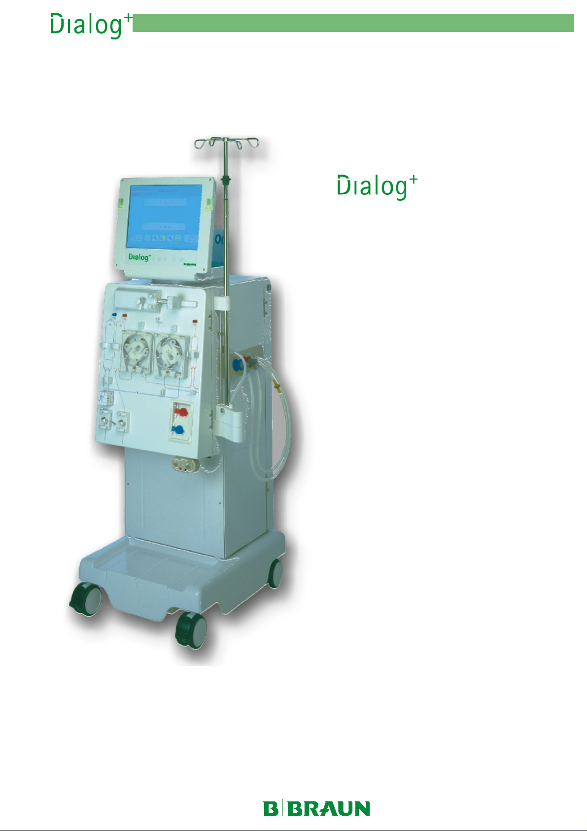
Page 1

2. Technical System Description 1/2003 2 - 1
Table of Content s Page
General Information 2-7
2.1 Overview Sub-Racks 2-8
2.1.1 Legend Overview Sub-Racks 2-8
2.2 Top Level Sub-Rack 2-9
2.2.1 Legend Top Level Sub-Rack 2-9
2.3 UF Sub-Rack 2-10
2.3.1 Legend UF Sub-Rack 2-10
2.4 DF Sub-Rack 2-11
2.4.1 Legend DF Sub-Rack 2-11
2.5 Water Inlet Sub-Rack 2-12
2.5.1 Legend Water Inlet Sub-Rack 2-12
2.6 Rinsing Bridge 2-13
2.6.1 Legend Rinsing Bridge 2-13
2.7 Rear Door 2-14
2.7.1 Legend Rear Door 2-14
2.8 TFT Monitor 2-15
2.8.1 Legend TFT Monitor 2-15
2.9 Power Board 1 PB1 2-16
2.9.1 Legend Power Board 1 PB1 2-16
2.10 Power Board 2 PB2 2-17
2.10.1 Legend Power Board 2 PB2 2-17
2.11 Supervisor Board SB 2-18
2.11.1 Legend Supervisor Board SB 2-18
2.12 Controller Board CB 2-19
2.12.1 Legend Controller Board CB 2-19
2.13 Switch Mode Power Supply SMPS (Benning) 2-20
2.13.1 Legend Switch Mode Power Supply SMPS 2-20
2.14 Front Door 2-21
2.14.1 Legend Front Door 2-21
2.15 Flow Diagram 2-22
MT-MD-DE08C M.KAY
Dialog+_sm_Chapter 2_1-2003.doc/pdf <011003> ddmmyy
B. Braun Medizintechnologie GmbH
Page 2

2. Technical System Description 1/2003 2 - 2
2.15.1 Legend Flow Diagram 2-23
2.16 Description Flow Diagram 2-25
2.16.1 Water Inlet Section with Upline Tank 2-25
2.16.2 Degassing Circuit with Temperature System 2-26
2.16.3 Dialysate Processing 2-27
2.16.4 Central Bicarbonate and Concentrate Supply 2-28
2.16.5 BIC Cartridge Holder 2-28
2.16.6 Balance Chamber System 2-29
2.16.7 Working Principle Balance Chamber System 2-29
2.16.8 Ultrafiltration and Rinsing Bridge 2-31
2.16.9 Disinfection and Cleaning Program 2-31
2.17 Block Diagram 2-32
2.17.1 Legend Block Diagram 2-33
2.18 TFT Monitor 2-35
2.18.1 Description TFT Monitor 2-35
2.19 ABPM Option (Non-Invasive Blood Pressure Measurement) 2-37
2.19.1 Wiring Diagram ABPM Option 2-37
2.20 bioLogic RR Option (Automatic Blood Pressure Stabilisation) 2-38
2.21 Supervisor Board SB 2-39
2.21.1 Supervisor 2-39
2.21.1.1 Block Diagram Supervisor 2-39
2.21.1.2 Description Supervisor 2-39
2.22 Bicarbonate Conductivity Measurement 2-41
2.22.1 Block Diagram Bicarbonate Conductivity Measurement 2-41
2.22.2 Description Bicarbonate Conductivity Measurement 2-41
2.23 END Conductivity Measurement Controller 2-42
2.23.1 Description END Conductivity Measurement Controller 2-42
2.23.2 END Conductivity Measurement Supervisor 2-42
2.23.3 Block Diagram END Conductivity Measurement Supervisor 2-42
2.23.4 Description END Conductivity Measurement Supervisor 2-42
2.24 Temperature Measurement 2-43
2.24.1 Block Diagram Degassing Temperature Measurement 2-43
2.24.2 Design Degassing Temperature Measurement 2-43
2.24.3 Description Bicarbonate Temperature Measurement 2-43
MT-MD-DE08C M.KAY
Dialog+_sm_Chapter 2_1-2003.doc/pdf <011003> ddmmyy
B. Braun Medizintechnologie GmbH
Page 3

2. Technical System Description 1/2003 2 - 3
2.24.4 Description Dialysate Controller Temperature Measurement 2-43
2.24.5 Block Diagram Dialysate Supervisor Temperature
2-44
Measurement
2.24.6 Description Temperature Measurement Dialysate Supervisor 2-44
2.25 Level Measurement 2-44
2.25.1 Block Diagram Level Measurement Upline Tank 2-44
2.25.2 Description Level Measurement Upline Tank 2-44
2.26 Reed Contacts 2-45
2.26.1 Block Diagram Coupling Status 2-45
2.26.2 Description Coupling Status 2-45
2.27 Pressure Measurement 2-45
2.27.1 Block Diagram Venous Pressure Measurement 2-45
2.27.2 Description Venous Pressure Measurement 2-45
2.27.3 Block Diagram Arterial Pressure Measurement 2-46
2.27.4 Description Arterial Pressure Measurement 2-46
2.28 Blood Inlet Pressure Measurement 2-46
2.28.1 Block Diagram Blood Inlet Pressure Measurement 2-46
2.28.2 Description Blood Inlet Pressure Measurement 2-46
2.29 Level Sensors 2-47
2.29.1 Block Diagram Level Sensors Air Separator 2-47
2.29.2 Description Level Sensors Air Separator 2-47
2.30 Red Detector 2-47
2.30.1 Block Diagram Red Detector 2-47
2.30.2 Description Red Detector 2-47
2.31 Degassing Pressure Measurement and Dialysate Pressure
2-48
Measurement
2.31.1 Block Diagram Pressure Measurement 2-48
2.31.2 Description Pressure Measurement 2-48
2.32 Monitoring Analogue 12 V Voltage Supply 2-48
2.32.1 Block Diagram Monitoring of Analogue 12 V Voltage Supply 2-48
2.32.2 Description Monitoring of Analogue 12 V Voltage Supply 2-48
MT-MD-DE08C M.KAY
Dialog+_sm_Chapter 2_1-2003.doc/pdf <011003> ddmmyy
B. Braun Medizintechnologie GmbH
Page 4

2. Technical System Description 1/2003 2 - 4
2.33 Safety Air Detector SAD and Venous Red Detector RDV 2-49
2.33.1 Block Diagram SAD/RDV 2-49
2.33.2 General Information SAD 2-49
2.33.3 Description Safety Air Detector SAD 2-50
2.33.4 Description Venous Red Detector RDV 2-52
2.34 Blood Leak Detector 2-53
2.34.1 Block Diagram Blood Leak Detector 2-53
2.34.2 Description Blood Leak Detector 2-53
2.35 Controller Board CB 2-54
2.35.1 Block Diagram Controller Board 2-54
2.35.2 Description Controller Board 2-55
2.36 Power Board 1 PB1 2-57
2.36.1 Block Diagram Power Board 1 2-57
2.36.2 Description Power Board 1 2-57
2.37 Power Board 2 PB2 2-59
2.37.1 Block Diagram Power Board 2 2-59
2.37.2 Description Power Board 2 2-60
2.38 Heparin Pump Compact 2-62
2.38.1 Block Diagram Heparin Pump Compact 2-62
2.38.2 Description Heparin Pump Compact 2-62
2.39 Single Needle Cross Over 2-64
2.39.1 Block Diagram SN Cross Over 2-64
2.39.2 Description SN Cross Over 2-65
2.40 Staff Call (Option) 2-66
2.40.1 Block Diagram Staff Call 2-66
2.40.2 Description Staff Call 2-66
2.40.3 Operating Modes Staff Call System 2-67
2.40.4 Block Diagram Alarm Monitoring 2-67
2.40.5 Pin Assignment 2-67
2.41 Switch Mode Power Supply SMPS (Benning) 2-68
2.41.1 Block Diagram Switch Mode Power Supply 2-68
2.41.2 System Integration 2-69
2.41.3 Layout Switch Mode Power Supply SMPS 2-70
2.41.4 Wiring Diagram Switch Mode Power Supply SMPS with
Battery Option
2.41.5 Description Switch Mode Power Supply 2-72
MT-MD-DE08C M.KAY
Dialog+_sm_Chapter 2_1-2003.doc/pdf <011003> ddmmyy
2-71
B. Braun Medizintechnologie GmbH
Page 5

2. Technical System Description 1/2003 2 - 5
2.41.6 Pin Assignment Switch Mode Power Supply 2-72
2.42 Safety Concept 2-77
2.42.1 Block Diagram Safety Concept 2-77
2.42.2 Description Safety Concept 2-78
MT-MD-DE08C M.KAY
Dialog+_sm_Chapter 2_1-2003.doc/pdf <011003> ddmmyy
B. Braun Medizintechnologie GmbH
Page 6
2. Technical System Description 1/2003 2 - 6
with the options:
Double Pump
•
BIC Cartridge Holder
•
Central Concentrate Supply
•
MT-MD-DE08C M.KAY
Dialog+_sm_Chapter 2_1-2003.doc/pdf <011003> ddmmyy
B. Braun Medizintechnologie GmbH
Page 7

General Information
2. Technical System Description 1/2003 2 - 7
Operation is accomplished via a touch screen (TFT monitor). Two
microprocessor systems control and monitor the machine.
The hardware concept consists of the following systems:
Top Level System
•
Low Level System
•
Top Level System
Low Level System
The top level system consists of the following components:
Communication module
•
Top level controller TLC (motherboard)
•
Hard disk drive
•
Floppy disk drive
•
ABPM (option)
•
The communication between the user and the machine is performed via the
top level.
Example data exchange to communication module:
Entry via input mask of the touch screen or keyboard
•
Output via the output mask of the TFT monitor
•
Example data exchange to low level:
Transmitting and receiving of data from/to low level controller
•
The low level system consists of the following components:
Low level controller LLC
•
Supervisor SB
•
Power board PB1 and power board PB2
•
The low level controls and monitors all functions.
Example data exchange to top level controller:
Transmitting and receiving of data from/to low level controller
•
Example data exchange low level controller to supervisor:
Transmitting and receiving messages, data and commands from/to supervisor
•
All sensors are connected to the processor system via the supervisor board. The
actuators, motors and valves are driven via the power boards 1 and 2.
MT-MD-DE08C M.KAY
Dialog+_sm_Chapter 2_1-2003.doc/pdf <011003> ddmmyy
B. Braun Medizintechnologie GmbH
Page 8

2. Technical System Description 1/2003 2 - 8
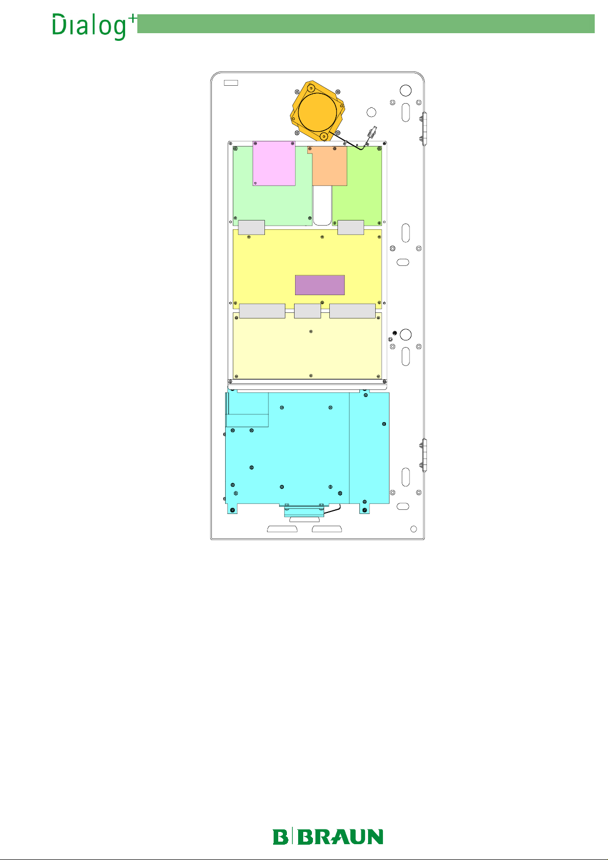
2.1 Overview Sub-Racks
Fig. : Overview Sub-Racks Rear View Dialog+
2.1.1 Legend Overview Sub-Racks
MT-MD-DE08C M.KAY
Dialog+_sm_Chapter 2_1-2003.doc/pdf <011003> ddmmyy
Top Level Sub-Rack
1
UF Sub-Rack
2
DF Sub-Rack
3
Water Inlet Sub-Rack
4
B. Braun Medizintechnologie GmbH
Page 9
2. Technical System Description 1/2003 2 - 9
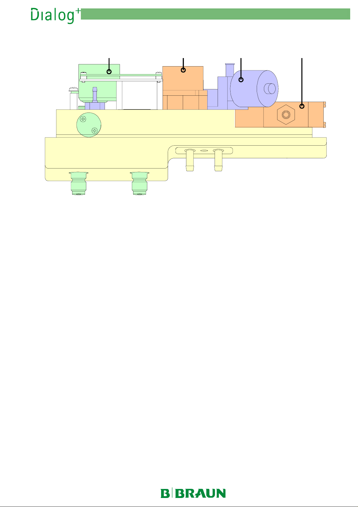
2.2 Top Level Sub-Rack
12
Fig. : Top Level Sub-Rack
2.2.1 Legend Top Level Sub-Rack
1
1 Hard Disk Drive
11
2222 Motherboard
MT-MD-DE08C M.KAY
Dialog+_sm_Chapter 2_1-2003.doc/pdf <011003> ddmmyy
B. Braun Medizintechnologie GmbH
Page 10
2. Technical System Description 1/2003 2 - 10
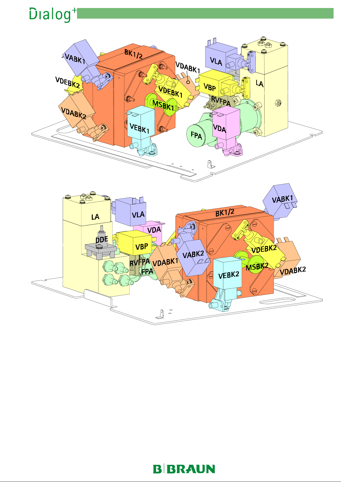
2.3 UF Sub-Rack
Fig. : UF Sub-Rack
2.3.1 Legend UF Sub-Rack
Air Separator LA
Air Separator Valve VLA
Balance Chamber BK1/2
Bypass Valve VBP
Dialyser Inlet Throttle DDE
Dialyser Inlet Valve VDEBK1
Dialyser Inlet Valve VDEBK2
Dialyser Outlet Valve Balance Chamber VABK1
MT-MD-DE08C M.KAY
Dialog+_sm_Chapter 2_1-2003.doc/pdf <011003> ddmmyy
LA
LALA
VBP
VBPVBP
VLA
VLAVLA
BK1/2
BK1/2BK1/2
VDEBK1
VDEBK1VDEBK1
VDEBK2
VDEBK2VDEBK2
DDE
DDEDDE
VABK1
VABK1VABK1
Dialyser Outlet Valve Balance Chamber VABK2
Dialyser Dialyser Outlet Valve Balance Chamber VDABK1
Dialyser Dialyser Outlet Valve Balance Chamber VDABK2
Inlet Valve Balance Chamber VEBK1
Inlet Valve Balance Chamber VEBK2
Membrane Position Sensor Balance Chamber MSBK1/2
Outlet Flow Pump FPA
Outlet Flow Pump Throttle RVFPA
FPA
FPAFPA
VEBK1
VEBK1VEBK1
VEBK2
VEBK2VEBK2
RVFPA
RVFPARVFPA
VABK2
VABK2VABK2
VDABK1
VDABK1VDABK1
VDABK2
VDABK2VDABK2
MSBK1/2
MSBK1/2MSBK1/2
B. Braun Medizintechnologie GmbH
Page 11
2. Technical System Description 1/2003 2 - 11
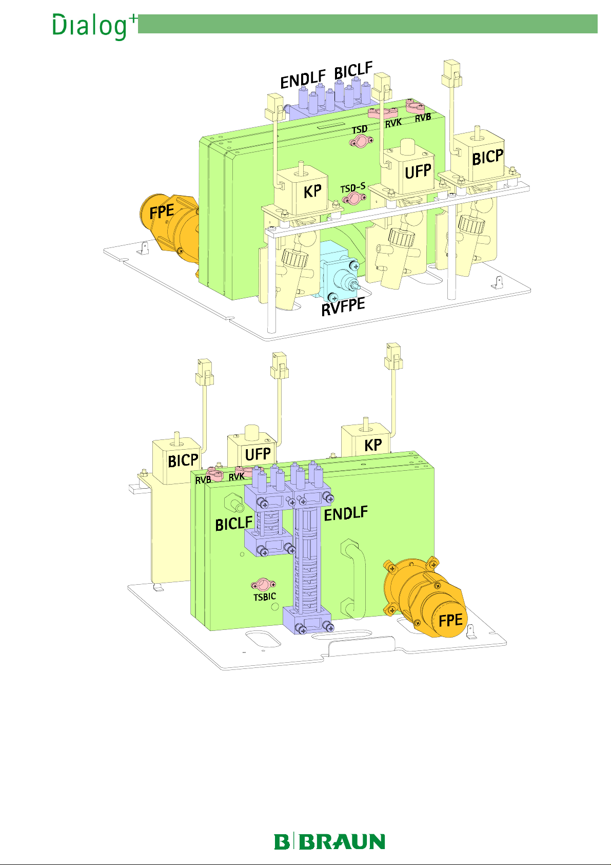
2.4 DF Sub-Rack
Fig. : DF Sub-Rack
2.4.1 Legend DF Sub-Rack
BIC Pump BICP
Bicarbonate Conductivity BICLF
Bicarbonate Temperature Sensor TSBIC
Bicarbonate Throttle RVB
Concentrate Pump KP
Concentrate Throttle RVK
Degassing Chamber EK
Degassing Control Valve RVE
MT-MD-DE08C M.KAY
Dialog+_sm_Chapter 2_1-2003.doc/pdf <011003> ddmmyy
BICP
BICPBICP
KP
KPKP
RVB
RVBRVB
EK
EKEK
RVK
RVKRVK
BICLF
BICLFBICLF
RVE
RVERVE
TSBIC
TSBICTSBIC
Degassing Pressure Sensor PE
Degassing Pump EP
Dialysate Temperature Sensor Supervisor TSD-S
Dialysate Temperature Sensor TSD
END Conductivity/Supervisor ENDLF/ENDLF-S
Inlet Flow Pump FPE
Inlet Flow Pump Throttle RVFPE
UF Pump UFP
UFP
UFPUFP
EP
EPEP
FPE
FPEFPE
PE
PEPE
TSD
TSDTSD
ENDLF/ENDLF-S
ENDLF/ENDLF-SENDLF/ENDLF-S
RVFPE
RVFPERVFPE
TSD-S
TSD-STSD-S
B. Braun Medizintechnologie GmbH
Page 12
2. Technical System Description 1/2003 2 - 12
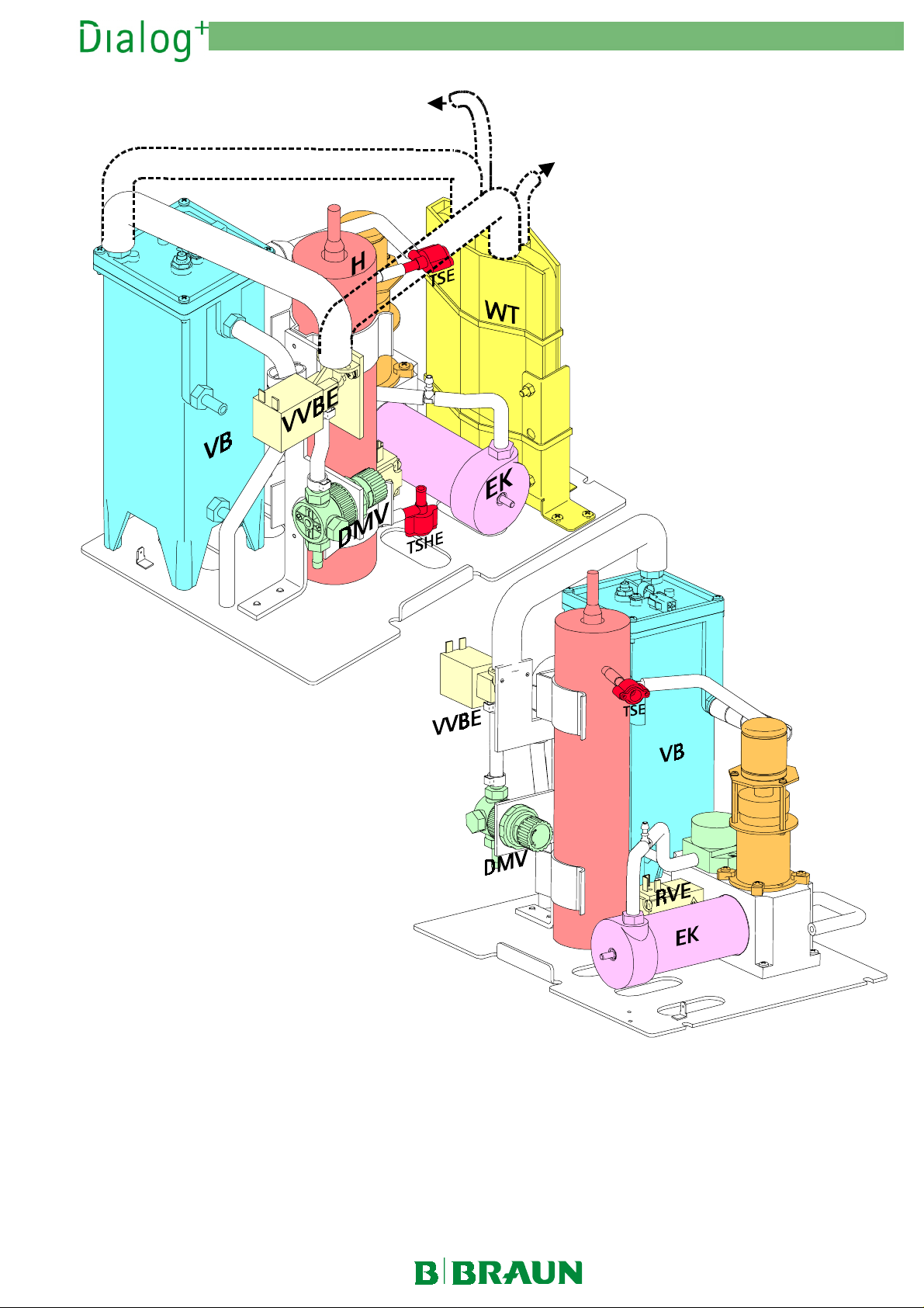
2.5 Water Inlet Sub-Rack
RVDA
Outlet
Ausgang
Fig. : Water Inlet Sub-Rack (with and without Heat Exchanger WT Option)
2.5.1 Legend Water Inlet Sub-Rack
Degassing Chamber EK
Degassing Control Valve RVE
Degassing Pressure Sensor PE
Degassing Pump EP
Degassing Temperature Sensor TSE
Heat Exchanger WT
EK
EKEK
RVE
RVERVE
EP
EPEP
WT (Option)
WTWT
PE
PEPE
TSE
TSETSE
H
PE
Heater HHHH
Heater Inlet Temperature Sensor TSHE
Heater Temperature Sensor TSH
Pressure Reducer Valve DMV
Upline Tank Inlet Valve VVBE
Upline Tank VB
VB
VBVB
DMV
DMVDMV
VVBE
VVBEVVBE
TSH
TSHTSH
TSHE
TSHETSHE
EP
MT-MD-DE08C M.KAY
Dialog+_sm_Chapter 2_1-2003.doc/pdf <011003> ddmmyy
B. Braun Medizintechnologie GmbH
Page 13
2.6 Rinsing Bridge
2. Technical System Description 1/2003 2 - 13
1
VD
Fig. : Rinsing Bridge
2.6.1 Legend Rinsing Bridge
234
PDA
VDE
BL
1
1 Disinfection Valve VD
11
2222 Pressure Sensor Dialysate Outlet PDA
VD
VDVD
PDA
PDAPDA
3333 Dialyser Inlet Valve VDE
4444 Blood Leak Detector BL
VDE
VDEVDE
BL
BLBL
MT-MD-DE08C M.KAY
Dialog+_sm_Chapter 2_1-2003.doc/pdf <011003> ddmmyy
B. Braun Medizintechnologie GmbH
Page 14
2.7 Rear Door
2. Technical System Description 1/2003 2 - 14
1
HOP
PB2
BIC-KV
PB1
SB
2
CB
SMPS
Fig. : Rear Door
2.7.1 Legend Rear Door
MT-MD-DE08C M.KAY
Dialog+_sm_Chapter 2_1-2003.doc/pdf <011003> ddmmyy
BIC Cartridge Holder Board BIC-KV
Controller Board CB
HDF Online Power Board HOP
HFS 2 Board HFS2
Fan (1111)
Power Board 1 PB1
CB
CBCB
HFS2 with TSHE (Option) (2222)
HFS2HFS2
PB1
PB1PB1
BIC-KV (Option)
BIC-KVBIC-KV
HOP (Option)
HOPHOP
Power Board 2 PB2
SAKA Board SAKA
Switch Mode Power Supply SMPS
Supervisor Board SB
Heater Inlet Temperature Sensor Board TSHE
PB2
PB2PB2
SAKA with TSHE (Option) (2222)
SAKASAKA
SMPS
SMPSSMPS
SB
SBSB
TSHE (2222)
TSHETSHE
B. Braun Medizintechnologie GmbH
Page 15
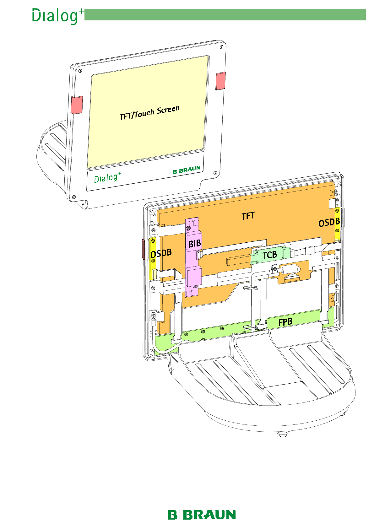
2.8 TFT Monitor
2. Technical System Description 1/2003 2 - 15
Fig. : TFT Monitor
2.8.1 Legend
MT-MD-DE08C M.KAY
Dialog+_sm_Chapter 2_1-2003.doc/pdf <011003> ddmmyy
TFT Monitor
Backlight Inverter Board
Front Panel Board
TFT Monitor
FPB
TFT
BIB
Optical Status Display Board
Touch Controller Board
Touch Screen
TCB
OSDB
B. Braun Medizintechnologie GmbH
Page 16
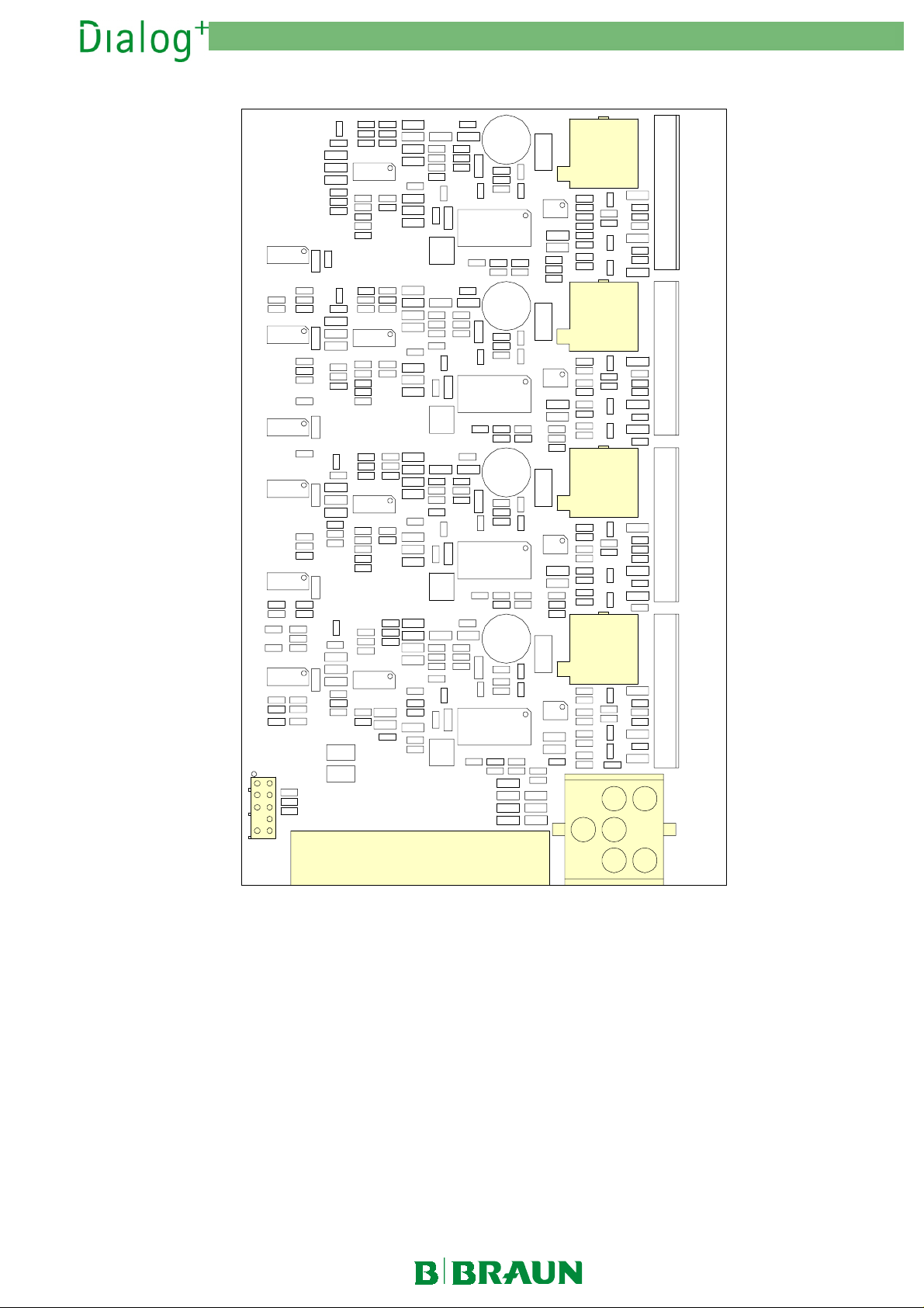
2.9 Power Board 1 PB1
2. Technical System Description 1/2003 2 - 16
V7
C37
V22
V20
R75
C50
R71
V5
V21
P5
R312
C148 C147 C146
V10
C93
V13
V4
C124C117
C39
C62
V24
V23
C65
C64
C86
V27
V26
R186
C89
C34
C15
V19
V17
R14R131
C18
R127 R1
V8
V25
C128C127C126 C125
R182
V11
V28
V1
V18
P6
P7
U15U14U13 U12
V40
V39V38V37 V36 V35V34 V33 V32 V31 V30 V29
P1
P4
P4
Fig. : Power Board 1 PB1
2.9.1 Legend Power Board 1 PB1
P1
P1 Arterial Blood Pump BPA
P1P1
P2
P2 Supervisor Board SB
P2P2
P3
P3 Voltage Supply
P3P3
P4
P4 Sensors Blood Pump
P4P4
Cover switch
SB
SBSB
BPA
BPABPA
P2
C17
P3
P5
P5 Inlet Flow Pump FPE
P5P5
P6
P6 Outlet Flow Pump FPA
P6P6
P7
P7 Degassing Pump EP
P7P7
FPE
FPEFPE
EP
EPEP
FPA
FPAFPA
MT-MD-DE08C M.KAY
Dialog+_sm_Chapter 2_1-2003.doc/pdf <011003> ddmmyy
B. Braun Medizintechnologie GmbH
Page 17
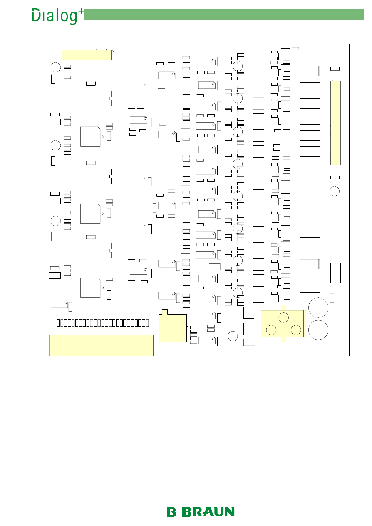
2.10 Power Board 2 PB2
P3
C78
2. Technical System Description 1/2003 2 - 17
P1
U26U25U24
P2
Fig. : Power Board 2 PB2
2.10.1 Legend Power Board 2 PB2
P1
P1 for Valves and SAKV:
P1P1
Upline Tank Inlet Valve RVVB
Degassing Control Valve RVE
Venous Tubing Clamp Currentles Closed SAKV-SG
Dialyser Outlet Valve VDA
Dialyser Inlet Valve VDE
Balance Chamber Valves VABK1/2, VDABK1/2, VEBK1/2, VDEBK1/2
Air Separator Valve VLA
Circulation Valve VZ
Bypass Valve VBP
VBP
VBPVBP
P5
RVVB
RVVBRVVB
RVE
RVERVE
SAKV-SG
SAKV-SGSAKV-SG
VDA
VDAVDA
VDE
VDEVDE
VABK1/2, VDABK1/2, VEBK1/2, VDEBK1/2
VABK1/2, VDABK1/2, VEBK1/2, VDEBK1/2VABK1/2, VDABK1/2, VEBK1/2, VDEBK1/2
VLA
VLAVLA
VZ
VZVZ
V47V46V45V44V43V42V41V40V39V38V37V36V35V34V33V32
P4
P2
P2 Supervisor Board SB
P2P2
P3
P3 Piston Pumps:
P3P3
Concentrate Pump KP
Bicarbonate Pump BICP
Ultrafiltration Pump UFP
P4
P4 Voltage Supply
P4P4
P5
P5 Disinfection Valve VD
P5P5
SB
SBSB
VD
VDVD
KP,
KPKP
BICP,
BICPBICP
UFP
UFPUFP
V3
C93
C83
MT-MD-DE08C M.KAY
Dialog+_sm_Chapter 2_1-2003.doc/pdf <011003> ddmmyy
B. Braun Medizintechnologie GmbH
Page 18
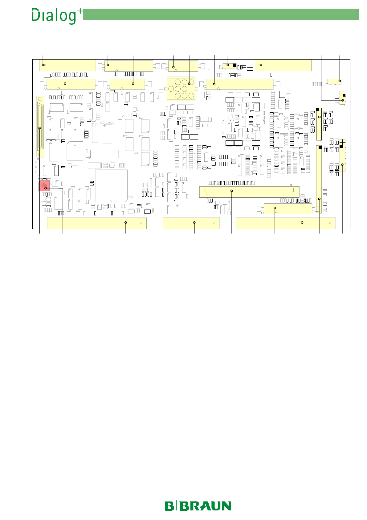
2.11 Supervisor Board SB
2. Technical System Description 1/2003 2 - 18
P11 P12 P8 P5
P9
14 P7
P6
P10 P15
P13P17
P19 K1 P2 P3 P18 P23 P1 P4 P16
Fig. : Supervisor Board SB
2.11.1 Legend Supervisor Board SB
P13
P1/P2/P3
P1/P2/P3 Controller Board CB
P1/P2/P3P1/P2/P3
P4
P4 BICSS/KSS/RDVLED/SAD RTS/TX/CTS/RX Signals
P4P4
P5
P5 Staff Call Signals
P5P5
P6
P6 BPV/PBS/SAKA Signals
P6P6
P7
P7 BL Signals
P7P7
P8
P8 REM/HOFF/HREL Signals
P8P8
P9
P9 SCB-RX/TX/CTS/RTS Signals
P9P9
P10
P10 BP/EP/FP Signals
P10P10
P11
P11 VVBE/KP/BICP/UFP/SKAV/VDE/VDA Signals
P11P11
P12
P12 Heparin Pump Signals
P12P12
CB
CBCB
P13 Pressure Sensor PBE
P13P13
P14
P14 Voltages +5 V/+24 VL/+24 VGB/+12 VAN/-12 VAN
P14P14
P15
P15 ENDLF/ENDLF-S/BICLF/TSD/TSD-S/TSBIC/TSE Signals
P15P15
P16
P16 Voltages +5 VREF/+12 VAN/-12 VAN
P16P16
P17
P17 Voltages +5 V/12 VD/-12 VD
P17P17
P18
P18 Extension Connector
P18P18
P19
P19 Communication Program Adapter
P19P19
K1
K1 Hardware Switch:
K1K1
Position 0: Therapy Mode
Position 2: TSM Service Program Mode
Position 3: Software Update Mode
PBE
PBEPBE
MT-MD-DE08C M.KAY
Dialog+_sm_Chapter 2_1-2003.doc/pdf <011003> ddmmyy
B. Braun Medizintechnologie GmbH
Page 19
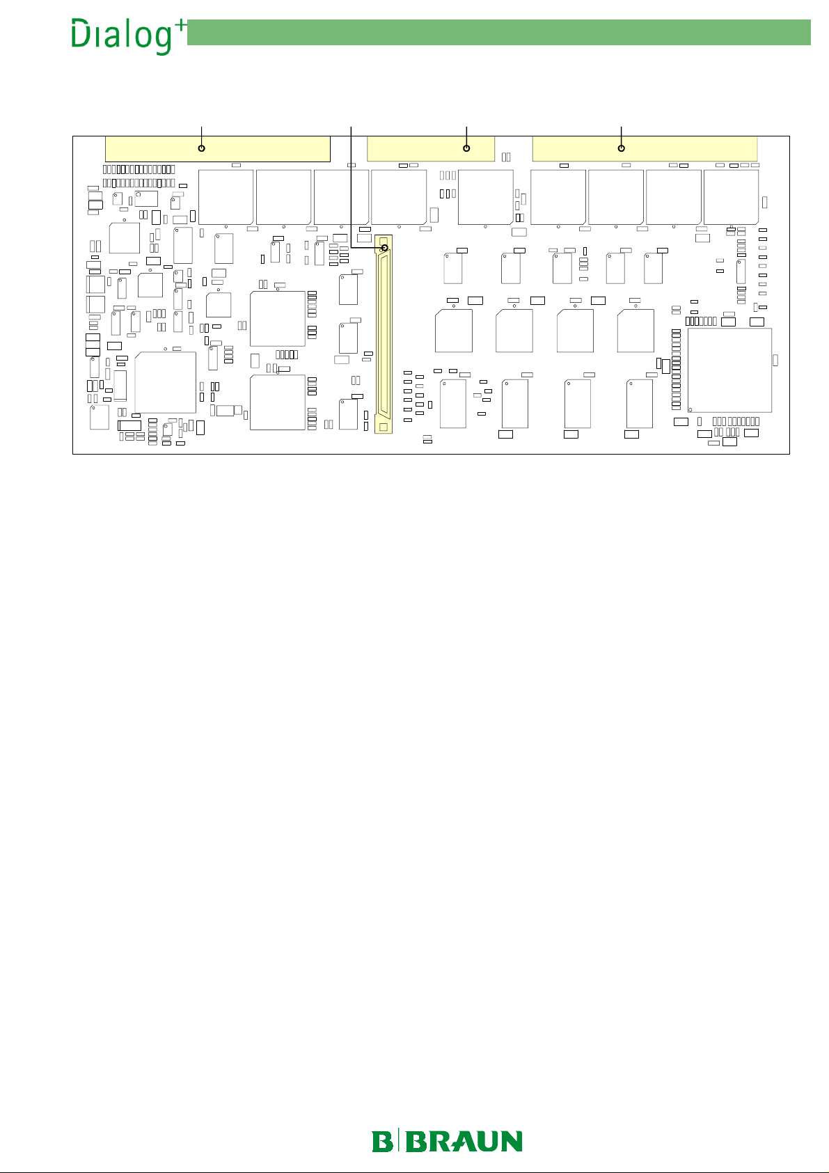
2.12 Controller Board CB
2. Technical System Description 1/2003 2 - 19
P1P3P5P2
U9 U8U6
U22
U25
U51
Fig. : Controller Board CB
U18
U26
U33
2.12.1 Legend Controller Board CB
P1/P2/P3
P1/P2/P3 Supervisor Board SB
P1/P2/P3P1/P2/P3
U2
U5
SB P5
SBSB
U3
P5 Program Adapter with Memory Card
P5P5
U12U11 U10
U1
MT-MD-DE08C M.KAY
Dialog+_sm_Chapter 2_1-2003.doc/pdf <011003> ddmmyy
B. Braun Medizintechnologie GmbH
Page 20
2. Technical System Description 1/2003 2 - 20
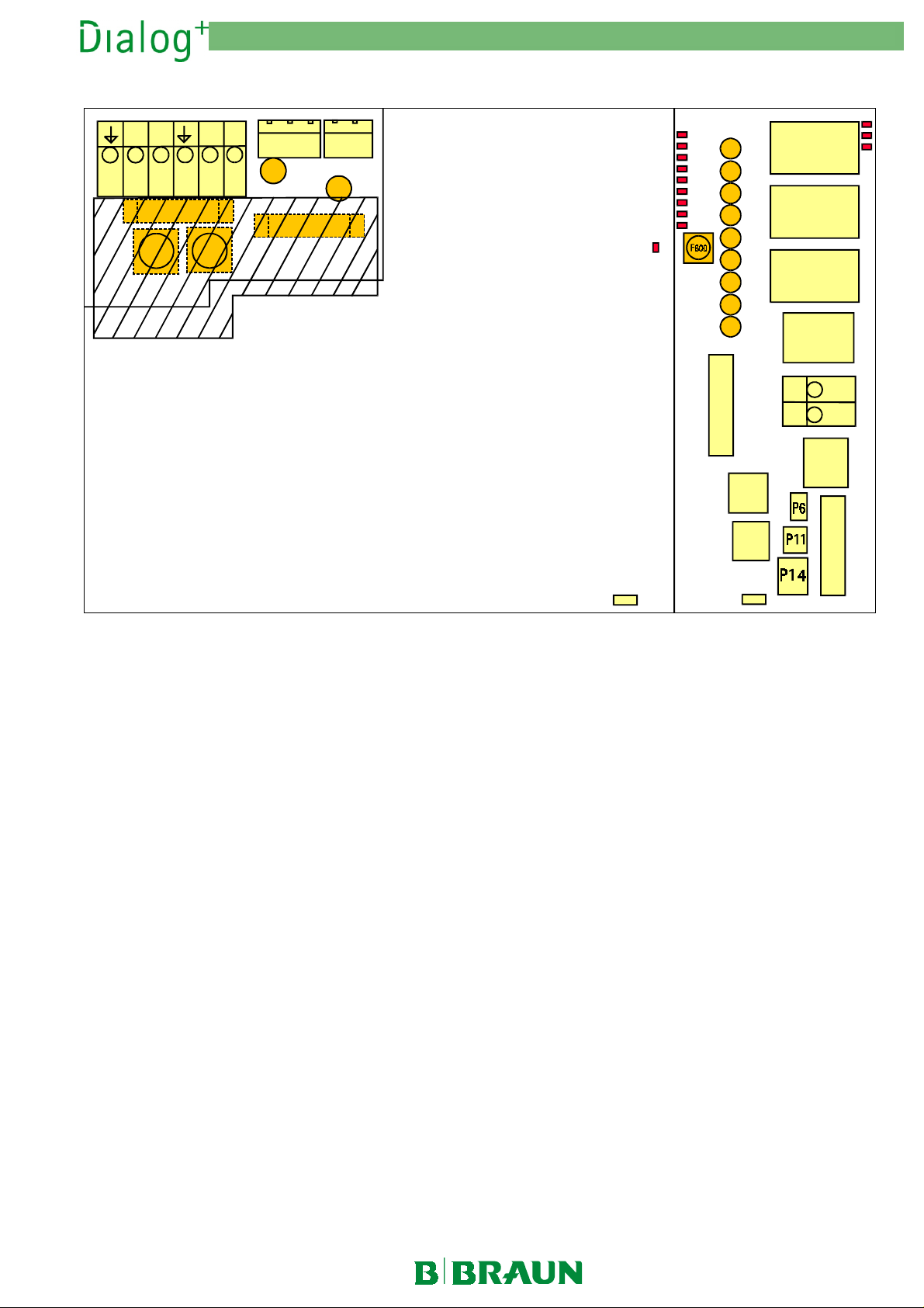
2.13 Switch Mode Power Supply SMPS (Benning)
PE3 N3 L3 N2 L2
X3
PE L N PE L1 N1
X1.3 X1.1 X1.2 X1.6 X1.5 X1.4
F4
X1
F5
F6
F1
Fig. : Switch Mode Power Supply SMPS (Benning)
F2
F3
X2
F1 T6.25A 6.3x32
F2 T6.25A 6.3x32
F3 T3.15A TR5
F4 T3.15A TR5
F5/F6 - 110/ 120V: F20A 6.3x32
- 230V: M10A 6.3x32
F301 T3.15A TR5
F302 T5.0A TR5
F303 T3.15A TR5
F304 T3.15A TR5
F401 T1.25A TR5
F402 T5.00A TR5
F403 T1.25A TR5
F500 T3.15A TR5
F600 M10.00A 6.3x32
F601 T3.15A TR5
F602 T3.15A TR5
+12VD / F401 - T1.25A TR5
+12VD / F402 - T5.00 A TR5
+12VAN / F4 03 - T1.25A TR5
+5VD / F303 - T3.15A TR5
+5VD / F30 2 - T5 . 00A TR5
+5VD / F301 - T3.15A TR5
+5VD / F304 - T3.15A TR5
+24 VGB / F602 - T3.15A TR5
+24VGB / F601 - T3.15A TR5
+24V
X100
LED
P13
F401
F402
F403
F303
F302
F301
F304
F602
F601
1
3
1
P7
P8
P101
1
3
1
3
1
3
P3
1
3
P12
P10
P4
1
P5
3
2
1
-
+
1
P9
4
1
1
2
P2
1
3
1
2.13.1 Legend Switch Mode Power Supply
SMPS
X1
X1 Mains Input, Heater
X1X1
X2
X2 -
X2X2
X3
X3 Fluid Warmer (via Relay)
X3X3
P2
P2 Supervisor/Watchdog, Service Board
P2P2
P3
P3 Battery Connection (Screw Terminal)
P3P3
P4
P4 Power Board 1/2
P4P4
P5
P5 Supervisor/Controller Board
P5P5
P6
P6 Floppy Disk Drive
P6P6
P7
P7 Options, Service Board (Service Tool)
P7P7
F1/F2
F1/F2 6.25 AT (6.3x32), Mains Input
F1/F2F1/F2
F3/F4
F3/F4 3.15 AT (TR5), Fluid Warmer + Monitor
F3/F4F3/F4
F5/F6
F5/F6 10 AM (6.3x32), Heater 1800 W (240 V)
F5/F6F5/F6
20 AF (6.3x32), Heater 1800 W (110/120 V)
F301
F301 3.15 AT (TR5), +5 VD
F301F301
F302
F302 5.00 AT (TR5), +5 VD
F302F302
F303/
F303/ 3.15 AT (TR5), +5 VD
F303/F303/
F304
F304
F304F304
P8
P8 ABPM
P8P8
P9
P9 Fan, Mains Switch
P9P9
P10
P10 PC
P10P10
P11
P11 Hard Disk Drive
P11P11
P12
P12 Options
P12P12
P13
P13 -
P13P13
P14
P14 EXT ON
P14P14
P101
P101 Service Watchdog
P101P101
X100
X100 Fan
X100X100
F401
F401 1.25 AT (TR5), +12 VD
F401F401
F402
F402 5.00 AT (TR5), +12 VD
F402F402
F403
F403 1.25 AT (TR5), +12 VAN
F403F403
F600
F600 10 AM (6.3x32), +24 VL
F600F600
F601/
F601/ 3.15 AT (TR5), +24 VGB
F601/F601/
F602
F602
F602F602
MT-MD-DE08C M.KAY
Dialog+_sm_Chapter 2_1-2003.doc/pdf <011003> ddmmyy
B. Braun Medizintechnologie GmbH
Page 21
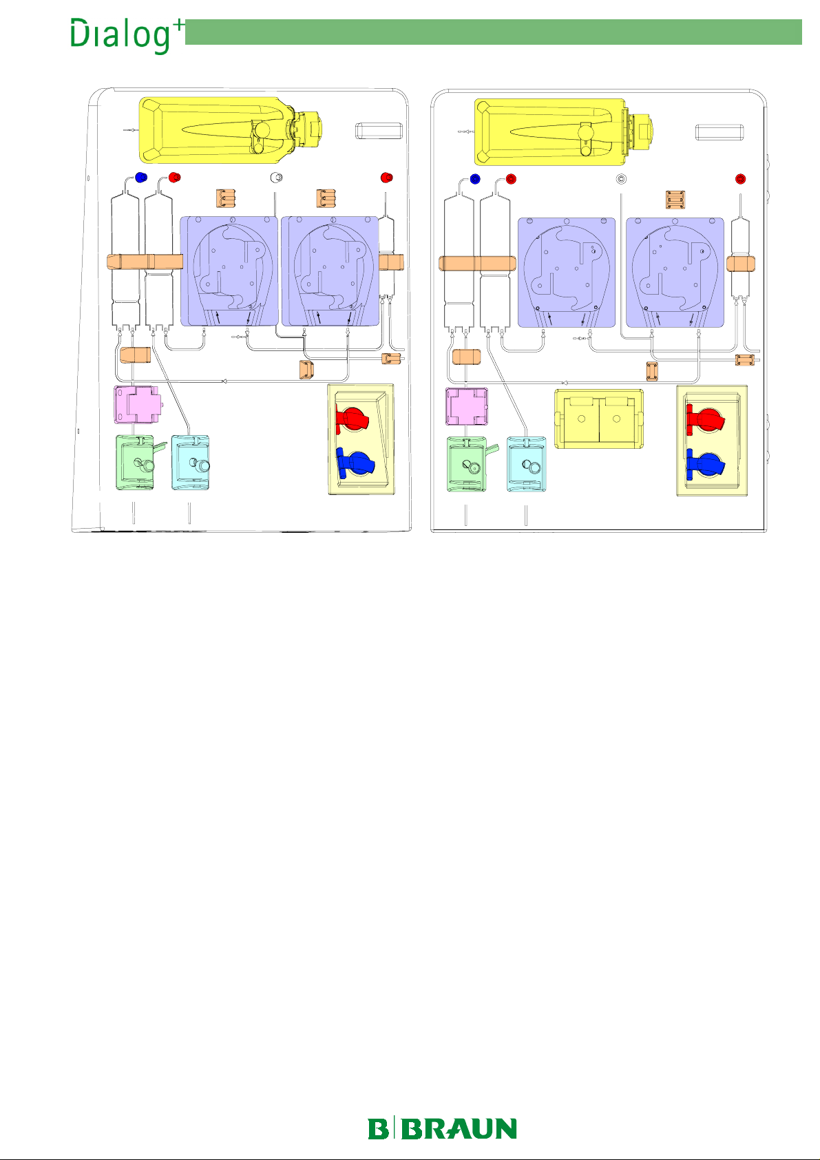
2.14 Front Door
2. Technical System Description 1/2003 2 - 21
HP
PV PA PBS/SN PBE
SN
SN
PBA PBV
SAD
SAKV-SG
SAKA
HP
PV PA
SN
SAD
SN
PBA PBV
PBS/SN
PBE
1111
2222
SAKASAKV-SG
2222
Fig. : Front Door
2.14.1 Legend Front Door
Arterial Blood Pump BPA
Arterial Pressure Sensor PA
Arterial Tubing Clamp SAKA-SG
BPA
BPABPA
PA
PAPA
SAKA-SG
SAKA-SGSAKA-SG
Cover for Suction Rods 2222
Heparin Pump Compact HP
Pressure Sensor PBE
PBE
PBEPBE
HP
HPHP
Pressure Sensor PBS/SN
Safety Air Detector SAD
PBS/SN
PBS/SNPBS/SN
SAD/Venous Red Detector RDV
SADSAD
RDV
RDVRDV
Substitution Port 1111
Venous Blood Pump BPV
Venous Pressure Sensor PV
Venous Tubing Clamp Currentles Closed SAKV-SG
BPV
BPVBPV
PV
PVPV
SAKV-SG
SAKV-SGSAKV-SG
MT-MD-DE08C M.KAY
Dialog+_sm_Chapter 2_1-2003.doc/pdf <011003> ddmmyy
B. Braun Medizintechnologie GmbH
Page 22
MT-MD-DE08C M.KAY
Dialog+_sm_Chapter 2_1-2003.doc/pdf <011003> ddmmyy
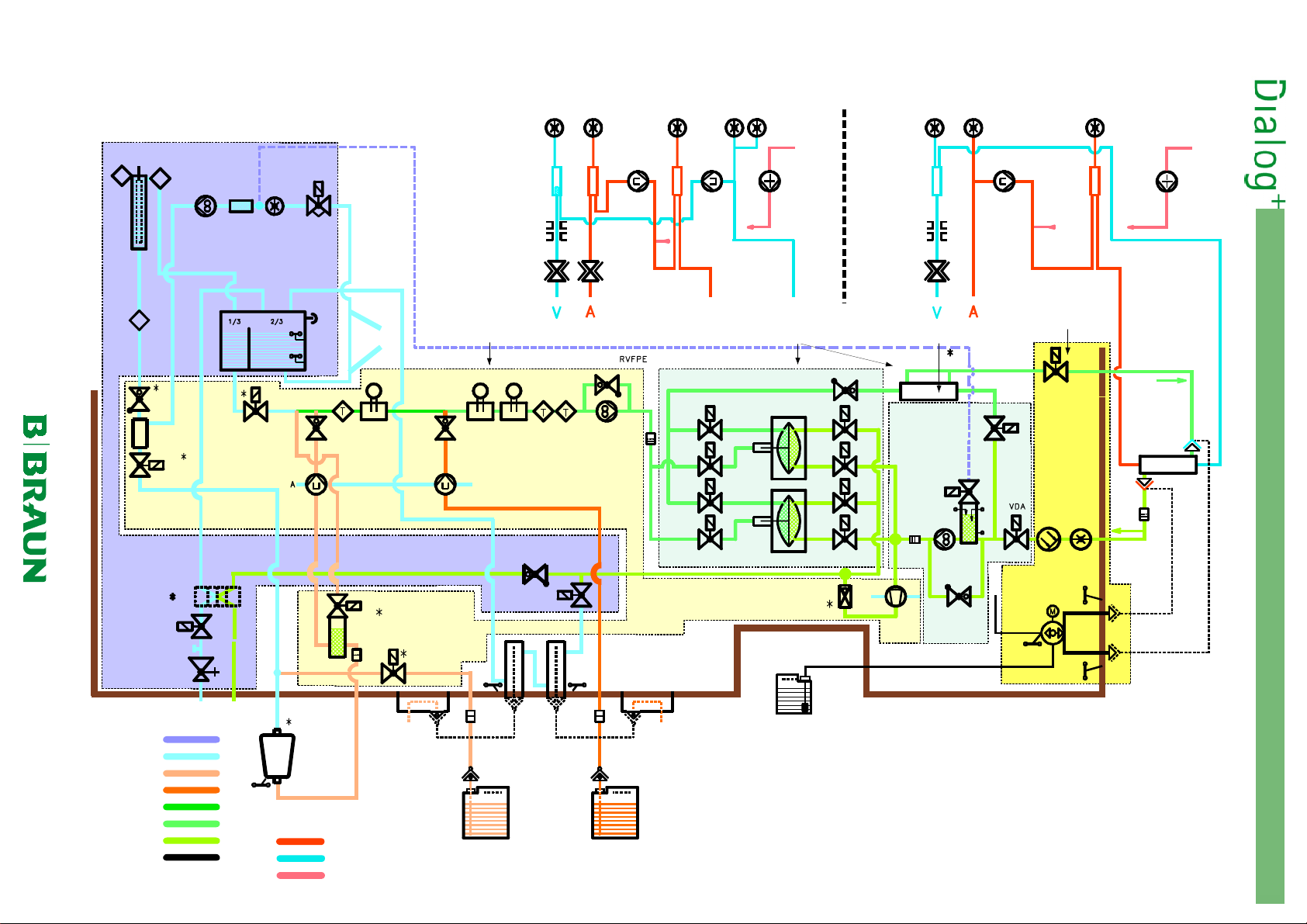
2.15 Flow Diagram
PA
PBE
PVPVPA
PBE
Double-NeedlePBS
TSETSH
T
T
EP EK PE
H
Water Sub-Rack
Wasser-Einschub
TSHE
T
DBK
LAB1
VBKO
WT
B. Braun Medizintechnologie GmbH
VVBE
DMV
VVB
BICP
RVE
SAD
RDV
SAKV-SG
SAKA
VB
DF Sub-Rack
DF-Einschub
NSVB
C
A
BPVBPA
Single-Needle
HP
UF Sub-Rack
UF-Einschub
SAD
RDV
SAKV-SG
Pyrogen Fi l t er
Pyrogenfilter
BPA
HP
Rinsing Bridge
Spülbrücke
2. Technical System Description 1/2003 2 - 22
DDE
RVB
TSBIC
BICLF
RVK TSD TSD-S
ENDLF-SENDLF
B
FPE
FBK1
VDEBK1
VEBK1
VDEBK2
MSBK1
BK1
VABK1
VDABK1
VABK2
VBP
VLA
VDE
V.D.
Z.D.
Dialysator
Dialyser
KP
LAB2
VBICP
FBIC
VBKS
Zentrale
Bicarbonat-
Versorgung
Central
Bicarbonate
Supply
RVDA
UFP
FBK2
LAFS
FPA
RVFPA
BL PDA
LA
Luft
SBS1
Air
VD
LVD
SBS2
VEBK2
MSBK2
VDABK2
BK2
FM
CB
VZ
FVD
S1
S2
Luft
Air
Wasser
Water
Bicarbonat
Bicarbonate
Konzentrat
Concentrate
Dialysierfluß 1
Dialysate Flow 1
Dialysierfluß 2
Dialysate Flow 2
Dialysierflüssigkeit
Dialysate
Desinfektionsmittel
Disinfectant
Optionen
Options
Wasser Z U
Water Inlet
*
Dialysat AB
Dialysate Outlet
BKUS
Blut Arteriell
Blood Arterial
Blut Venös
Blood Venous
Heparin
BVA
BICSS
FB
BE
BIC-Konzentrat
BIC Conce ntrate
KSS
FK
KE
Konzentrat
Säurekonzentrat
Concentrate
Aci d C oncentrat e
KVA
Zentrale
Konzentrat-
Versorgung
Central
Concentrate
Supply
FD
Disinfectant
(Rear Side of Unit)
Desinfektionsmittel
(Geräterückseite)
Page 23

2.15.1 Legend Flow Diagram
Abbreviation Description
2. Technical System Description 1/2003 2 - 23
BE
BICLF
BICP
BICSS
BK1
BK2
BL
BPA
BPV
BVA
DBK
DDE
DMV
EK
ENDLF
ENDLF-S
EP
FB
FBIC
FBK1
FBK2
FK
FM
FPA
FPE
FVD
H
HP
KE
KP
KSS
KVA
LA
LAB1
LAB2
LAFS
LVD
MSBK1
MSBK2
NSVB
PA
PBE
PBS
PDA
PE
PV
Bicarbonate Withdrawal Rod
Bicarbonate Conductivity
Bicarbonate Pump
Bicarbonate Rinsing Connection Sensor
Balance Chamber 1
Balance Chamber 2
Blood Leak Detector
Arterial Blood Pump
Venous Blood Pump
Bicarbonate Supply Connection (Central Supply)
Throttle Bicarbonate Cartridge Holder
Throttle Dialyser Inlet
Pressure Reducer Valve
Degassing Chamber
END Conductivity
END Conductivity Supervisor
Degassing Pump
Filter Bicarbonate
Filter Bicarbonate Cartridge
Filter Balance Chamber 1
Filter Balance Chamber 2
Filter Concentrate
Flowmeter
Outlet Flow Pump
Inlet Flow Pump
Filter from Dialysate
Heater
Heparin Syringe Pump
Concentrate Withdrawal Rod
Concentrate Pump
Concentrate Rinsing Connector Sensor
Concentrate Supply Connector (Central Supply)
Air Separator
Air Separator BIC Cartrige Holder 1
Air Separator BIC Cartrige Holder 2
Air Separator Level Sensors
Light Barrier Disinfection Valve
Membrane Position Sensor Balance Chamber 1
Membrane Position Sensor Balance Chamber 2
Level Sensor Upline Tank
Arterial Pressure Sensor
Pressure Sensor Blood Inlet
Blood Pressure Control Sensor
Pressure Sensor Dialysate Outlet
Degassing Pressure Sensor
Venous Pressure Sensor
MT-MD-DE08C M.KAY
Dialog+_sm_Chapter 2_1-2003.doc/pdf <011003> ddmmyy
B. Braun Medizintechnologie GmbH
Page 24

2. Technical System Description 1/2003 2 - 24
RDV
RVB
RVDA
RVE
RVFPA
RVFPE
RVK
RVUF
SAD
SAKA
SAKV-SD
SBS1
SBS2
TSBIC
TSD
TSD-S
TSE
TSH
TSHE
UFP
VABK1
VABK2
VB
VBICP
VBKO
VBKS
VBP
V.D.
VD
VDA
VDABK1
VDABK2
VDE
VDEBK1
VDEBK2
VEBK1
VEBK2
VLA
VVB
VVBE
VZ
WT
Z.D.
Venous Red Detector
Throttle Bicarbonate
Throttle Dialysate Valve
Degassing Control Valve
Throttle Flow Pump Outlet
Throttle Flow Pump Inlet
Throttle Concentrate
Throttle Ultrafiltration
Safety Air Detector
Arterial Tubing Clamp
Venous Tubing Clamp Currentles Closed
Rinsing Bridge Connector Sensor 1
Rinsing Bridge Connector Sensor 2
Bicarbonate Temperature Sensor
Dialysate Temperature Sensor
Dialysate Temperature Sensor Supervisor
Degassing Temperarture Sensor
Thermal Fuse Heater Element
Heater Inlet Temperature Sensor
Ultrafiltration Pump
Outlet Valve Balance Chamber 1
Outlet Valve Balance Chamber 2
Upline Tank
Bicarbonate Pump Valve
Bicarbonate Cartridge Holder Top Valve
Bicarbonate Cartridge Holder Concentrate Rod Valve
Bypass Valve
Dialyser Coupling (from Dialysate)
Disinfection Valve
Dialyser Outlet Valve
Dialyser Outlet Valve Balance Chamber 1
Dialyser Outlet Valve Balance Chamber 2
Dialyser Inlet Valve
Dialyser Inlet Valve Balance Chamber 1
Dialyser Inlet Valve Balance Chamber 2
Inlet Valve Balance Chamber 1
Inlet Valve Balance Chamber 2
Air Separator Valve
Upline Tank Valve
Upline Tank Inlet Valve
Circulation Valve
Heat Exchanger
Dialyser Coupling (to Dialysate)
MT-MD-DE08C M.KAY
Dialog+_sm_Chapter 2_1-2003.doc/pdf <011003> ddmmyy
B. Braun Medizintechnologie GmbH
Page 25

2. Technical System Description 1/2003 2 - 25
2.16 Description Flow Diagram
The flow diagram can be divided into six sections:
2.16.1 Water Inlet Section with Upline
Tank
The water inlet section has the following components
Water Inlet Section with Upline Tank
•
Degassing Circuit with Temperature System
•
Dialysate Processing
•
Balance Chamber
•
Ultrafiltration
•
Rinsing Bridge
•
TSE
VB
WT
Pressure Reducer Valve DMV
•
Upline Tank Inlet Valve VVVVVBE
•
Upline Tank VB
•
Level Sensors Upline Tank NSVB
•
Heat Exchanger WT
•
VB
VBVB
DMV
DMVDMV
WT (Option)
WTWT
KSS
NSVB
RVE
RVB
VBE (2/2 way valve)
VBEVBE
NSVB
NSVBNSVB
Pressure Reducer Valve DMV
Pressure Reducer Valve DMV
Pressure Reducer Valve DMVPressure Reducer Valve DMV
The pressure reducer valve DMV limits the
pressure of the inlet water (e.g. osmosis water)
to a maximum of approx. 1.3 bar.
Upline Tank Inlet Valve
Upline Tank Inlet Valve VVVVVBE
Upline Tank Inlet Valve Upline Tank Inlet Valve
The valve VVBE is time-delayed controlled via
the level sensor NSVB (top) in the upline tank
VB. The delay time depends on the dialysate
flow.
Level Sensors Upline Tank NSVB
Level Sensors Upline Tank NSVB
Level Sensors Upline Tank NSVBLevel Sensors Upline Tank NSVB
The level sensors are mounted in the upline
tank.
VBE
VBEVBE
VZ
VVBE
DMV
Fig. : Water Inlet with Upline Tank
MT-MD-DE08C M.KAY
Dialog+_sm_Chapter 2_1-2003.doc/pdf <011003> ddmmyy
RVDA
NSVB
NSVB top:
NSVBNSVB
closed - VVBE is closed
NSVB
NSVB bottom (monitoring low water level):
NSVBNSVB
closed (alarm) - Water inlet is disturbed
- Heater is switched off
Heat Exchanger WT (Option)
Heat Exchanger WT (Option)
Heat Exchanger WT (Option)Heat Exchanger WT (Option)
The cold inlet water can be warmed up via the
optional heat exchanger WT. Thereby the heat
consumption to heat up the water can be
reduced.
B. Braun Medizintechnologie GmbH
Page 26

2.16.2 Degassing Circuit with
Temperature System
2. Technical System Description 1/2003 2 - 26
The degassing circuit with temperature system has the following components:
Degassing Control Valve RVE
•
RVE
RVERVE
Degassing Control Valve RVE
Degassing Control Valve RVE
Degassing Control Valve RVEDegassing Control Valve RVE
Degassing Pressure Sensor PE
Degassing Pressure Sensor PE
Degassing Pressure Sensor PEDegassing Pressure Sensor PE
Degassing Pump EP
Degassing Pump EP
Degassing Pump EPDegassing Pump EP
Heater Element H
Heater Element H
Heater Element HHeater Element H
Thermal Fuse Heater Element TSH
Thermal Fuse Heater Element TSH
Thermal Fuse Heater Element TSHThermal Fuse Heater Element TSH
Degassing Temperature Sensor TSE
Degassing Temperature Sensor TSE
Degassing Temperature Sensor TSEDegassing Temperature Sensor TSE
Degassing Pressure Sensor PE
•
Degassing Chamber EK
•
Degassing Pump EP
•
Thermal Fuse Heater Element TSH
•
Temperature Sensor Heater Inlet TSHE
•
Heater Element HHHH
•
Degassing Temperature Sensor TSE
•
The control valve RVE, pressure sensor PE, degassing chamber EK and degassing
pump EP produce and measure a negative pressure respectively. The negative
pressure is produced to separate the dissolved gas from the water.
The control valve RVE reduces the flow (throttle principle) depending on the
measured pressure at the pressure sensor PE. Thereby the desired negative
pressure is gained between the control valve RVE and the degassing pump EP.
The value of the negative pressure is approx. -500 mmHg and thus always
higher than the lower pressure of the dialysate behind the dialyser. The
degassing pump works with constant speed, which is determined by the
dialysate, unless the negative pressure is insufficient at the smallest opening of
RVE. Then the speed of EP is increased.
The heater H has an integrated thermal fuse TSH as a thermal cut-off. The
temperature sensor TSE measures the actual temperature posterior to the
heater.
EP
EPEP
EK
EKEK
PE
PEPE
TSH
TSHTSH
TSE
TSETSE
TSHE
TSHETSHE
TSE
T
Temperature Control
Temperature Control The temperature of the water inlet determines the amount of heat which the
Temperature ControlTemperature Control
heater must supply, to replace the amount of heat (dialysate flow and dialysate
temperature) withdrawn by the drainage.
The differential temperature between the heater inlet (TSHE) and the heater
outlet (TSE) determines the controlled variable for the heater, depending on the
dialysate flow and dialysate temperature.
VLA
TSH
T
EP
EK
PE
RVE
H
T
TSHE
zum VB/to VB
Fig. : Degassing Circuit with Temperature System
MT-MD-DE08C M.KAY
Dialog+_sm_Chapter 2_1-2003.doc/pdf <011003> ddmmyy
vom VB/f rom VB
B. Braun Medizintechnologie GmbH
Page 27

2.16.3 Dialysate Processing
2. Technical System Description 1/2003 2 - 27
The dialysate processing has the following components:
The main components of the dialysate preparation are the bicarbonate
Bicarbonate Concentrate Pump BICP
•
Bicarbonate Throttle RVB
•
Bicarbonate Temperature Sensor TSBIC
•
Bicarbonate Conductivity BICLF
•
Concentrate Pump KP
•
Concentrate Throttle RVK
•
END Conductivity ENDLF
•
END Conductivity Supervisor ENDLFS
•
Dialysate Temperature Sensor TSD
•
Dialysate Temperature Sensor Supervisor TSDS
•
Inlet Flow Pump FPE
•
Inlet Flow Pump Throttle RVFPE
•
concentrate pump BICP and the concentrate pump KP, with the conductivity
cells BICLF and ENDLF and a flow pump FPE. The flow pump FPE delivers the
dialysate. The bicarbonate concentrate, which is added via the bicarbonate
pump BICP, is measured by the conductivity measurement cell BICLF. Thereby
the pump can control the given conductivity set-point value.
KP
KPKP
ENDLF
ENDLFENDLF
FPE
FPEFPE
RVB
RVBRVB
RVK
RVKRVK
BICLF
BICLFBICLF
ENDLFS
ENDLFSENDLFS
RVFPE
RVFPERVFPE
TSD
TSDTSD
BICP
BICPBICP
TSBIC
TSBICTSBIC
TSDS
TSDSTSDS
vom VB
from VB
TSBIC
The concentrate or acid concentrate addition has the same working principle.
The nonreturn valves RVB and RVK stablise the dosage of the bicarbonate and
concentrate.
The temperature sensors TSBIC and TSD are responsible for:
the temperature compensation of the conductivity measurement and
•
temperature measurement TSD after the addition of cold concentrate
•
(second measurement sensor for temperature system) and thus
compensation of temperature loss.
The conductivity sensor ENDLFS is an independent monitoring unit (supervisor).
The geometry of the ENDLFS sensor is different (but has the same cell constant)
than the ENDLF sensor of the controller. Thereby a deposit on the sensor can be
identified. The temperature compensation is carried out by the temperature
sensor TSDS. The temperature sensor additionally monitors the dialysate flow
temperature for the supervisor. The ENDLFS and TSDS sensors have no influence
on the respective control.
The throttle RVFPE prevents a high pressure build-up and thus a bursting of
tubing if the flow path is blocked behind FPE. If the set pressure is reached
RVFPE is opened and the fluid can circulate.
RVFPE
BICLF
ENDLF
ENDLF-S
TSD
TSD-S
T
RVB
BICP
vom Bicarbonat
Fig. : Dialysate Processing
MT-MD-DE08C M.KAY
Dialog+_sm_Chapter 2_1-2003.doc/pdf <011003> ddmmyy
from Bicarbonate
RVK
KP
vom Konzentrat
from Concentrate
T
T
zu Bilanzierungskamme rn
FPE
to Bal ance Chambers
B. Braun Medizintechnologie GmbH
Page 28

2.16.4 Central Bicarbonate and
Concentrate Supply
2.16.5 BIC Cartridge Holder
2. Technical System Description 1/2003 2 - 28
A canister or central supply can be selected via the bicarbonate and
concentrate supply connetion BVA and KVA. The supply connection is an option.
The flow pump FPE guarantees a continuous control of the desired dialysate
flow into the balance chambers.
The flow rate is determined by the filling time of the balance chamber. The flow
pump FPE is controlled via the predetermined volume of the chamber and a
continuous detection of the position of the membrane.
DBK
DBK Throttle Bicarbonate Cartridge Holder
DBKDBK
LAB1
LAB1 Air Separator BIC Cartrige Holder 1
LAB1LAB1
VBKO
VBKO Bicarbonate Cartridge Holder Top Valve
VBKOVBKO
VBKS
VBKS Bicarbonate Cartridge Holder Concentrate Rod Valve
VBKSVBKS
Throttle Bicarbonate Cartridge Holder
Throttle Bicarbonate Cartridge HolderThrottle Bicarbonate Cartridge Holder
DBK ensures a constant pressure (approx. 200 mmHg) during the filling of the
bicarbonate cartridge.
Air Separator BIC Cartrige Holder 1
Air Separator BIC Cartrige Holder 1Air Separator BIC Cartrige Holder 1
LAB1 ensures that only fluid can enter the bicarbonate cartridge.
Bicarbonate Cartridge Holder Top Valve
Bicarbonate Cartridge Holder Top ValveBicarbonate Cartridge Holder Top Valve
The bicarbonate cartridge is filled to the limit presure (200 mmHg) after VBKO
opens.
Bicarbonate Cartridge Holder Concentrate Rod Valve
Bicarbonate Cartridge Holder Concentrate Rod ValveBicarbonate Cartridge Holder Concentrate Rod Valve
The bicarbonate cartridge is vented during preparation and in therapy, i.e. VBKO
closes and VBKS opens for a short time. This is repeated in regular intervals
during threapy. VBKS is opened after the end of the therapy to empty the
bicarbonate cartridge.
vom Vorlau f behälter
from Upline Tank
DBK
VBICP
VBICP Bicarbonate Pump Valve
VBICPVBICP
LAB2
LAB2 Air Separator BIC Cartrige Holder 2
LAB2LAB2
VVB
VVB Upline Tank Valve
VVBVVB
VVB RVB
BICP
LAB1
Bicarbonate Pump Valve
Bicarbonate Pump ValveBicarbonate Pump Valve
If VBICP is opened the liquid level in LAB2 is increased. VBICP switches the BIC
pump in bypass after the end of the therapy to empty the bicarbonate
cartridge.
Air Separator BIC Cartrige Holder 2
Air Separator BIC Cartrige Holder 2Air Separator BIC Cartrige Holder 2
LAB2 serves as a buffer chamber for the bicarbonat e cartridge (and canis ter) to
prevent conductivity malfunctions/deviations during therapy.
Upline Tank Valve
Upline Tank ValveUpline Tank Valve
VVB cuts off the main flow after the end of the therapy to empty the
bicarbonate cartridge via FPE (VBICP and VBKS are opened).
BICLF
TSBIC
RVK
ENDLF
ENDLF-S
TSD
FPE
TSD-S
KP
VBICP
LAB2
VBKO
Fig. : BIC Cartridge Holder (Option)
MT-MD-DE08C M.KAY
Dialog+_sm_Chapter 2_1-2003.doc/pdf <011003> ddmmyy
FBIC
VBKS
BVA
FB
BE
B. Braun Medizintechnologie GmbH
Page 29

2.16.6 Balance Chamber System
2. Technical System Description 1/2003 2 - 29
The balance chamber system has the following components:
Balance Chamber BK1
•
BK1
BK1BK1
2.16.7 Working Principle Balance
Chamber System
Phase 1:
Balance Chamber BK2
•
Balance Chamber Dialyser Inlet Valve VDEBK1
•
Balance Chamber Inlet Valve VEBK1
•
Balance Chamber Membrane Position Sensor MSBK1
•
Balance Chamber Dialyser Outlet Valve VDABK1
•
Balance Chamber Outlet Valve VABK1
•
BK2
BK2BK2
VDEBK1 and VDEBK2
VDEBK1VDEBK1
VEBK1 and VEBK2
VEBK1VEBK1
VABK1 and VABK2
VABK1VABK1
VEBK2
VEBK2VEBK2
VDABK1 and VDABK2
VDABK1VDABK1
VABK2
VABK2VABK2
VDEBK2
VDEBK2VDEBK2
MSBK1 and MSBK2
MSBK1MSBK1
MSBK2
MSBK2MSBK2
VDABK2
VDABK2VDABK2
The measurement and control of the ultrafiltration rate is accomplished by the
double balance chamber system and the ultrafiltration pump UFP.
Both balance chambers BK1 and BK2 are identical. The chambers have flexible
membranes, which can be moved to both sides. The membranes devide the
chambers into two sub-compartments. The flow direction is defined by the
membranes and the eight solenoid valves. The position of the membranes is
measured by inductive membrane position sensors MSBK1 and MSBK2. The
membrane position sensors (ferrites) are connected to the membranes and each
move in a respective coil MSBK1 and MSBK2.
The balance chamber BK1 is filled with dialysate at the beginning of phase 1.
The membrane is in right position. The valves VDEBK1 and VDABK1 are opened.
The balance chamber BK1 is filled by the outlet flow pump FPA, via valve
VDABK1. Simultaneously the dialysate is removed from the balance chamber
BK1 via valve VDEBK1. Phase 1 is completed and the membrane is in left
position (see figure).
RVDA
FPE
VDEBK1
VEBK1
VDEBK2
VEBK2
VZ
MSBK1
MSBK2
The balance chamber BK2 is filled with fresh dialysate during this period. The
used dialysate from the previous phase 2 is drained (see description phase 2).
PE/RVE
BK1
BK2
VABK1
VDABK1
VABK2
VDABK2
DDE
VLA
LA_FS
FPA
UFP
LA
RVFPA
VBP
VDA
VDE
BL
open
offen
PDA
closed
geschlossen
Fig. : Phase 1 Balance Chamber
MT-MD-DE08C M.KAY
Dialog+_sm_Chapter 2_1-2003.doc/pdf <011003> ddmmyy
B. Braun Medizintechnologie GmbH
Page 30

2. Technical System Description 1/2003 2 - 30
Phase 2: After phase 1 is completed there is an automatic switch to the filled balance
chamber BK2 to obt ain a constant flow in the dialyse r. The complete cylce is
repeated in phase 2, i.e. valves VDEBK2 and VDABK2 are opened. The balance
chamber BK2 is filled via valve VDABK2. Simultaneously the dialysate is drained
from the balance chamber BK2 via valve VDEBK2. Phase 2 is completed and the
menbrane is in left position (see figure).
Simultaneously the balance chamber BK1 is filled with fresh dialysate.
Therefore valve VEBK1 is opened. Valve VABK1 is also opened, to initiate the
flow path for the used dialysate to the drain. The membrane moves to the right
position.
The outlet fluid volume is equal to the returned fluid volume, due to the closed
balance chamber system
The fluid volume removed from the closed system via the ultrafiltration pump
UFP is replaced from the blood in the dialyser and equals the precise
ultrafiltration volume.
The system is initialised in preparation, i.e. the membrane sensors are
automatically calibrated and the speed of the flow pumps FPE and FPA are
determined. Thus a synchronisation of the membranes is guaranteed, and the
pump speeds for the desired flow are determined.
FPE
RVDA
Fig. : Phase 2 Balance Chamber
VDEBK1
VEBK1
VDEBK2
VEBK2
VZ
MSBK1
MSBK2
BK1
BK2
VABK1
VDABK1
VABK2
VDABK2
DDE
VLA
LA_FS
FPA
UFP
PE/RVE
LA
RVFPA
VBP
VDA
VDE
BL
open
offen
closed
geschlossen
PDA
MT-MD-DE08C M.KAY
Dialog+_sm_Chapter 2_1-2003.doc/pdf <011003> ddmmyy
B. Braun Medizintechnologie GmbH
Page 31

2. Technical System Description 1/2003 2 - 31
2.16.8 Ultrafiltration and Rinsing Bridge
The main flow path and bypass have the following components:
Dialyser Inlet ThrottleDDE
•
DDE
DDEDDE
Dialyser Inlet Valve VDE
•
Dialyser Outlet Valve VDA
•
Bypass Valve VBP
•
Outlet Flow Pump FPA
•
VBP
VBPVBP
VDE
VDEVDE
FPA
FPAFPA
VDA
VDAVDA
The flow path for the main flow and bypass are determined by the valves VDE,
VDA and VBP. The built up flow from the flow pump FPA is stabilised by the
throttle DDE. Valves VDE and VBP are closed for sequential therapy
(ultrafiltration without dialysate flu id flow). The ultrafiltrate removal is carried
out by the ultrafiltration pump UFP.
Further components are:
Red sensitive blood leak detector BL
•
Pressure sensor PDA which monitors the dialysate pressure (also used to
•
calculate TMP)
Air separator LA with built in level sensors LAFS and air separator valve VLA
•
Throttle RVDA functions as a resistance to stabilise the flow of FPE
•
The throttle RVFPE prevents a high pressure build-up and thus a bursting of
tubing if the flow path is blocked behind FPE. If the set pressure is reached
RVFPE is opened and the fluid can circulate.
The fluid level is lowered in the air separator LA, due to air bubbles from the
dialyser (degassing or possible leakages). The air separator valve VLA is opened
if the fluid level is lower than the bottom level sensor. The fluid level is
increased, due to the negative pressure for the degassing range, until the level
reaches the upper level sensor of the air separator LA.
2.16.9 Disinfection and Cleaning Program
The user can select a disinfection or cleaning program. The position of the
couplings are checked by the sensors BICSS, KSS, SBS1 and SBS2. Then the UF
pump UFP starts running and builds up a negative pressure against the closed
disinfection valve VD. At approx. -200 mmHg VD opens and disinfectant is
sucked in by the UFP.
The circulation va lve VZ is open and fluid fl ow s i nto the upl i ne ta nk VB, because
the throttle RVDA acts as a forward resistance. Thereby a quicker heat-up in the
hot cleaning program is achieved and thus a reduction of disinfectant. There is
no flow of fluid to the drain during suction, heat-up and circulation.
MT-MD-DE08C M.KAY
Dialog+_sm_Chapter 2_1-2003.doc/pdf <011003> ddmmyy
B. Braun Medizintechnologie GmbH
Page 32

2.17 Block Diagram
2. Technical System Description 1/2003 2 - 32
Fig. : Block Diagram
MT-MD-DE08C M.KAY
Dialog+_sm_Chapter 2_1-2003.doc/pdf <011003> ddmmyy
B. Braun Medizintechnologie GmbH
Page 33

2.17.1 Legend Block Diagram
Supervisor Board SB
Controller Sensoren
Supervisor Sensors
BICLF
BICSS
ENDLF
KSS
NSVB
PBE
PE
SBS1
SBS2
TSBIC
TSD
TSE
ENDLFS
TSDS
2. Technical System Description 1/2003 2 - 33
Bicarbonate Conductivity
Bicarbonate Rinsing Connection Sensor
END Conductivity
Concentrate Rinsing Connector Sensor
Level Sensor Upline Tank
Pressure Sensor
Degassing Pressure Sensor
Rinsing Bridge Connector Sensor 1
Rinsing Bridge Connector Sensor 2
Bicarbonate Temperature Sensor
Dialysate Temperature Sensor
Degassing Temperarture Sensor
END Conductivity Supervisor
Dialysate Temperature Sensor Supervisor
Controller/Supervisor
Sensors/Actuators
BKUS
BL
FEDFFS
FEDHDFS
LAFS
MSBK1
MSBK2
PA
PDA
PSABFS
PSAUS
PV
RDV
SAD
TSHE
VBE
VBICP
VBKS
VBKO
VDFF
VSAA
VSAE
VSB
VVB
Bottom Bicarbonate Sensor
Blood Leak Detector
DF Filter Detection Sensor
HD Filter Detection Sensor
Air Separator Level Sensors
Membrane Position Sensor Balance Chamber 1
Membrane Position Sensor Balance Chamber 2
Arterial Pressure Sensor
Pressure Sensor Dialysate Outlet
Port Substition Drain Sensor
Port Substition Outlet Sensor
Venous Pressure Sensor
Venous Red Detector
Safety Air Detector
Heater Inlet Temperature Sensor
Filter Vent Valve
BIC Pump Valve
BIC Concentrate Suction Rod Valve
Top BIC Cartridge Valve
DF Filter Valve
Substitution Connection Outlet Valve (drain)
Substitution Connection Inlet Valve
Substitution Bypass Valve
Upline Tank Valve
MT-MD-DE08C M.KAY
Dialog+_sm_Chapter 2_1-2003.doc/pdf <011003> ddmmyy
B. Braun Medizintechnologie GmbH
Page 34

Power Board 1 PB1
Power Board 2 PB2
BPA
EP
FPA
FPE
BICP
KP
RVE
SAKV-SG
UFP
VABK1
VABK2
VB
VBP
VD
VDA
VDABK1
VDABK2
VDE
VDEBK1
VDEBK2
VEBK1
VEBK2
VLA
VVBE
VZ
2. Technical System Description 1/2003 2 - 34
Arterial Blood Pump
Degassing Pump
Outlet Flow Pump
Inlet Flow Pump
Bicarbonate Pump
Concentrate Pump
Degassing Control Valve
Venous Tubing Clamp Currentles Closed
Ultrafiltration Pump
Outlet Valve Balance Chamber 1
Outlet Valve Balance Chamber 2
Upline Tank
Bypass Valve
Disinfection Valve
Dialyser Outlet Valve
Dialyser Outlet Valve Balance Chamber 1
Dialyser Outlet Valve Balance Chamber 2
Dialyser Inlet Valve
Dialyser Inlet Valve Balance Chamber 1
Dialyser Inlet Valve Balance Chamber 2
Inlet Valve Balance Chamber 1
Inlet Valve Balance Chamber 2
Air Separator Valve
Upline Tanke Inlet Valve
Circulation Valve
Heparin Pump Comfort Board
SN-Crossover Board
Power Supply
HP
BPV
PBS
PBS-S
SAKA
TSH
Heparin Pump Compact
Venous Blood Pump
Pressure Single Needle
Pressure Single Needle Supervisor
Arterial Tubing Clamp
H
Heater Element
Thermal Fuse Heater Element
MT-MD-DE08C M.KAY
Dialog+_sm_Chapter 2_1-2003.doc/pdf <011003> ddmmyy
B. Braun Medizintechnologie GmbH
Page 35

2.18 TFT Monitor
2.18.1 Description TFT Monitor
2. Technical System Description 1/2003 2 - 35
TFT Monitor
TFT Monitor
TFT MonitorTFT Monitor
The 15" TFT monitor (TFT=thin film transistor) has a resolution of
1024 x 768 XGA. The TFT housing can be swivelled.
Keyboard
Keyboard
KeyboardKeyboard
The following settings can be performed via the keyboard:
Start/stop arterial blood pump BPA
•
Increase/decrease speed of arterial blood pump BPA
•
Acknowledge alarms
•
Acknowledge entries
•
Display:
+-
Battery Option
Keys:
Decrease speed of arterial blood pump BPA
Fig. : TFT Monitor witt Touch Screen
+-
. : Keyboard Membrane
Fig
stop
stop
Start and stop arterial blood pump BPA
Increase speed of arterial blood pump BPA
Acknowledge alarms
Acknowledge entries
start
stop
The
key has two integrated yellow LEDs. In both the
and keys two red LEDs are in tegrated. All keys switch a
resistor on the supervisor communication board to ground GNDD.
Optical Status Displays OSD
An optical status display OSD is integrated into the TFT hou sing
(top left and right). The red LED is cyclically checked during
therapy. The following operating statuses are displayed:
. : Rear
Fig
MT-MD-DE08C M.KAY
Dialog+_sm_Chapter 2_1-2003.doc/pdf <011003> ddmmyy
TFT Monitor
Red
Red: Alarm
RedRed
Yellow
Yellow: Warning
YellowYellow
Green
Green: Trouble-free operation
GreenGreen
Touch Screen/Touch Controller Board TCB
The touch screen has a resolution of 4096 x 4096 with a 4-wire
to technique and has an RS 232 interface (9600 Baud).
B. Braun Medizintechnologie GmbH
Page 36

2. Technical System Description 1/2003 2 - 36
Backlight Inverter Board BIB
Front Panel Board FPB
The backlight inverter board drives four lamps for the TFT
monitor.
The front panel board has five keys. If a key is pressed a signal is
generated for the TLC and LLS.
Three LEDs are integrated in each key. Thus the signals for the
TLC are generated. The alarm acknowledge key additionally
generates a signal for the LLS.
A charge LED is integrated on the FPB for the battery option.
The volume can be set with a potentiometer. A signal is
generated for the TLC. The LLS monitors the signal via the
current and the pulse.
The signals are generated for the TLC and LLS for the optical
status displays OSDs.
The signals for the brightness of the LEDs (OSD) are generated
for the TLC.
The signal (brightness for the TFT) for the backlight inverter
board BIB is generated for the TLC.
The signal for the parallel port is generated for the TLC.
The signal for the RS 232 interface is generated for the LLS.
Loudspeaker
A loudspeaker for audible alarms is either integrated in the basic
housing. The volume can be set with a potentiometer on the FPB
(TFT housing, rear bottom left).
MT-MD-DE08C M.KAY
Dialog+_sm_Chapter 2_1-2003.doc/pdf <011003> ddmmyy
B. Braun Medizintechnologie GmbH
Page 37

2. Technical System Description 1/2003 2 - 37
2.19 ABPM Option (None-Invasive Blood
Pressure Measurement)
ABPM Option
ABPM Module/ABPM Interface Board
Dialog+
Voltage Supply
Multi I/O
2.19.1 Wiring Diagram ABPM Option
Floppy Disk Drive
Diskettenlaufwerk
A none-invasive blood pressure measurement is possible with the ABPM option
(automatic blood pressure measurement). The ABPM option works on an
oscillometrical basis for the automatical control of the symptomatic hypertonia
during dialysis.
The ABPM option can be retrofitted in the dialysis machine.
The ABPM option consists of the ABPM module and the ABPM interface board.
The ABPM option will be assembled in the basic housing (left side).
The ABPM module is connected to the switch mode power supply via the ABPM
interface board (connector P8).
The ABPM module is connected to the motherboard (COM3 port) via the ABPM
interface board.
ABPM Module
ABPM-Modul
left side basic housing
linke Seite Grundgehäuse
Motherboard
GX1LCD
COM3
1
COM4
COM1COM2
Fig. : Wiring Diagram ABPM Option
P1
P2
ABPM Inte rface Bo ar d
ABPM Interface-Board
Switch Mode Power Supply SMPS
Schaltnetzteil SMPS
1
1
P8
MT-MD-DE08C M.KAY
Dialog+_sm_Chapter 2_1-2003.doc/pdf <011003> ddmmyy
B. Braun Medizintechnologie GmbH
Page 38

2. Technical System Description 1/2003 2 - 38
2.20 bioLogic RR Option (Automatic Blood
Pressure Stabilisation)
The bioLogic RR option can be installed and activated subsequently. The ABPM
option must be present in the Dialog+ to run the bioLogic RR option.
The software for the bioLogic RR option is installed via an installation diskette.
The diskette is automatically marked (assigned to the machine) during
installation and subsequently can only be used for this specific Dialog+
machine.
•
Note
Note
NoteNote
If the TLC software has to be reinstalled or the hard disk drive has to be
replaced:
Activate the option bioLogic RR, i.e. use the bioLogic RR installation diskette
which belongs to the respective machine and activate again the option.
Installation diskette for bioLogic RR for SW ≥ 6.20
MT-MD-DE08C M.KAY
Dialog+_sm_Chapter 2_1-2003.doc/pdf <011003> ddmmyy
B. Braun Medizintechnologie GmbH
Page 39

2.21 Supervisor Board SB
2.21.1 Supervisor
2.21.1.1 Block Diagram Supervisor
2. Technical System Description 1/2003 2 - 39
Digitale
Eingänge
Digital
Inputs
Digitale Eingänge
Analoge Eingänge
Digital e Ausgänge
Digitale
Ausgänge
Digital
Outputs
2
E PROM
Digital Inputs
Analog Inputs
Digital Outputs
RAM
Daten/Adressbus
Data/Address Bus
CPU
80C535
Reset
Generator
Speicher-
Karte
Memory
Card
ACIA
Serielle
Schnittstelle
Serial
Interface
Serielle Schnitt stel le
Serial Interface
Datenaustausch Controller
Data Communication Controller
2
E PROM
Seriell
Serial
DIABUS
TLCB
LLCB
Fig. : Block Diagram Supervisor Board
2.21.1.2 Description Supervisor
The supervisor board connects the low level controller LLC with the peripheral.
Additionally the supervisor (monitoring microprocessor) is integrated on the
board. The following components are assembled on the board. The sensors are
directly connected:
Bicarbonate Conductivity Measurement
•
END Conductivity Measurement Controller
•
END Conductivity Measurement Supervisor
•
DegassingTemperature Measurement
•
Bicarbonate Temperature Measurement
•
Dialysate Temperature Measurement Controller
•
Dialysate Temperature Measurement Supervisor
•
Level Sensors Upline Tank
•
Reed Contacts Rinsing Bridge
•
Venous Pressure Sensor
•
Arterial Pressure Sensor
•
Level Sensors in the Air Separator
•
Red Sensors
•
Degassing Pressure Measurement
•
Blood Inlet Pressure Measurement
•
Additionally the following components are available for monitoring and control:
MT-MD-DE08C M.KAY
Dialog+_sm_Chapter 2_1-2003.doc/pdf <011003> ddmmyy
Monitoring of analogue 12 V supply voltage
•
Synchronisation of actual pump values
•
B. Braun Medizintechnologie GmbH
Page 40

2. Technical System Description 1/2003 2 - 40
The signal processing for the low level controller and supervisor are on the
supervisor board. All sensors are connected to this board via plugs. The power
board BP1 and PB2 are also connected to this board. Signals for single sensors
of the processor system are also processed separately.
Microprocessor
80C535 CPU
Address Decoding Logic
2
Serial E
PROM
The supervisor has the following components:
80C535 CPU
•
2
PROM
E
•
Connection for:
Memory Card
•
Digital Inputs and Outputs
•
Analogue Inputs
•
Serial Interface
•
Communication with the Controller
•
Reset Generator
•
The supervisor CPU (central processing unit) has the following data:
8 Bit Processor
•
256 x 8 RAM (internal)
•
6 8 Bit I/O Ports
•
3 16 Bit Counter
•
1 Serial Interface with max. 9600 Baud
•
8 Bit AD Converter with 8 Multiplexer Inputs
•
2
The processor is equipped with a 32 kB external RAM and a 1 MB E
program code is stored in the E
2
The serial E
PROM stores the supervisor sensor calibration data. The data is
2
PROM. The RAM is used to store data.
PROM. The
stored during calibration in the TSM service program and loaded before a
therapy is activated.
Digital Inputs and Outputs
Analogue Inputs
Serial Interface
Communication with the Controller
Reset Generator
Additional signal memory (latches) for the in- and outputs are available,
because the implemented ports of the 535 processor are limited. The outputs
have open colectors. All inputs have TTL level.
The processor has an internal 8 bit AD converter. The input voltage range is 0 to
5 V. The supervisor monitors the analogue sensors conductivity, temperature
and pressure, these are directly connected with the inputs.
The serial interface is used for the communication with the front panel board
FPB (via the SUPBUS). The tr ansfer rate is 9600 baud. The interface works in full
duplex mode with V 24 level.
An additional ACIA (asynchronous communications interface adapter) is
implemented for the communication with the top level controller via the
DIABUS. The ACIA works in full duplex mode with 19200 baud and 24 V level.
The communication with the controller is realised by a parallel interface. The
interface has signal memory (latches).
The reset generator resets the processor after th e su pply volt age is sw itched on.
Thereby the program can start at a predefind address.
MT-MD-DE08C M.KAY
Dialog+_sm_Chapter 2_1-2003.doc/pdf <011003> ddmmyy
B. Braun Medizintechnologie GmbH
Page 41

2.22 Bicarbonate Conductivity
Measurement
2.22.1 Block Diagram Bicarbonate
Conductivity Measurement
+5 VREF
Referenzspannung
Reference Voltage
CLK4
Takt 400 0 Hz
Cycle 4000 Hz
Geschalteter
Tiefpaß
Gleichrichter
Low-Pass
Rectifier
BIC-LF
Ausgangssignal
Output Signal
Fig. : Block Diagram Bicarbonate Conductivity Measurement
2. Technical System Description 1/2003 2 - 41
BICLF-A
Sendeelektrode
Transmitter Electrode
Switch
Verstärker
Amplifier
BICLF-C
Empfangselektrode
Receiver Electrode
2.22.2 Description Bicarbonate
Conductivity Measurement
The conductivity of the dialysate is determined by a resistance measurement.
The measurement is performed by an alternating current with approx. 4 kHz.
The calibration is accomplished by the controller. The measurement cell has two
transmitter electrodes and a receiver electrode with a fixed cell constant.
A transmitter voltage for the transmitter electrode BICLF_A signal is
•
generated from the +5 VREF reference voltage by the CLK4 signal (4000 Hz).
The signal runs through the fluid.
•
The received BICLF_C signal is amplified.
•
The switched rectifier converts the a.c. voltage to a d.c. voltage BIC_LF.
•
A d.c. voltage, which is proportional to the conductivity is fed to the AD
•
converter.
The temperature compensation and linearisation of the conductivity is
•
performed by the controller.
MT-MD-DE08C M.KAY
Dialog+_sm_Chapter 2_1-2003.doc/pdf <011003> ddmmyy
B. Braun Medizintechnologie GmbH
Page 42

2. Technical System Description 1/2003 2 - 42
2.23 END Conductivity Measurement
Controller
2.23.1 Description END Conductivity
Measurement Controller
The design of the END conductivity measurement controller is identical with
the bicarbonate conductivity measurement in paragraph 2.22.
2.23.2 END Conductivity Measurement
Supervisor
2.23.3 Block Diagram END Conductivity
Measurement Supervisor
Taktgenerator
4000 Hz
Pulse Generator
4000 Hz
Referenzspannung
Reference
Voltage
Geschalteter
END-S-LF
Ausgangssignal
Output Signal
Fig. : Block Diagram END Conductivity Measurement Supervisor
2.23.4 Description END Conductivity
Measurement Supervisor
Gleichrichter
Switch
Rectifier
ENDLF-S-A
Sendeelektrode
Transmitter Electrode
Verstärker
Amplifier
ENDLF-S-C
Empfangselektrode
Receiver Electrode
The END conductivity measurement of the dialysate by the supervisor is in
MT-MD-DE08C M.KAY
Dialog+_sm_Chapter 2_1-2003.doc/pdf <011003> ddmmyy
principle identical with the controller. The differences are:
The independent generation of the reference voltage and the clock signal
•
Dimension of the Measurement Cell
•
The calibration is
performed
by the supervisor software.
B. Braun Medizintechnologie GmbH
Page 43

2.24 Temperature Measurement
2.24.1 Block Diagram Degassing
Temperature Measurement
2. Technical System Description 1/2003 2 - 43
+5 VREF
Referenzspannung
Reference Voltage
TSE, TSHE, TSBIC, TSD
Ausgangssignal
Output Signal
Fig. : Block Diagram Degassing Temperature Measurement
U/I Wandler
U/I Converter
2.24.2 Design Degassing Temperature
Measurement
PTC
Offset
Verstärker
Amplifier
Tiefpaß
Low-Pass
The temperature of the fluid is measured by a PTC resistor (PTC positive
temperature coefficient).
2.24.3 Description Bicarbonate
Temperature Measurement
The design is identical with the degassing temperature measurement in
2.24.4 Description Dialysate Controller
Temperature Measurement
The design is identical with the degassing temperature measurement in
The PTC has a constant current flow of < 0.1 mA
•
The voltage drop is measured and amplified in a differential amplifier
•
An offset voltage is added to lift the zero point. Thereby the measurement
•
range of the AD converter has an optimal working condition.
The output voltage is fed to the AD converter on the supervisor board via a
•
low-pass filter.
paragraph 2.24.1.
paragraph 2.24.1.
MT-MD-DE08C M.KAY
Dialog+_sm_Chapter 2_1-2003.doc/pdf <011003> ddmmyy
B. Braun Medizintechnologie GmbH
Page 44

2. Technical System Description 1/2003 2 - 44
2.24.5 Block Diagram Dialysate Supervisor
Temperature Measurement
Referenz-
Spannung
Reference
U/I Wandler
U/I Converter
Voltage
PTC
Offset
Verstärker
Amplifier
TSD-S
Ausgangssignal
Output Signal
Fig. : Block Diagram Dialysate Supervisor Temperature Measurement
2.24.6 Description Dialysate Supervisor
Temperature Measurement
The temperature measurement of the supervisor has an independent reference
2.25 Level Measurement
2.25.1 Block Diagram Level Measurement
Upline Tank
Tiefpaß
Low-Pass
voltage source. Thus a cross-interference with the temperature sensors of the
controller is excluded.
+5 V
NSVBO
NSVBU
Fig. : Block Diagram Upline Tank
2.25.2 Description Level Measurement
Upline Tank
The level sensor in the upline tank has two reed contacts. The contacts are
switched by an internal magnet in a float ball. Pull-up resistors are on the
input. The query is carried out by the digital inputs of the controller.
MT-MD-DE08C M.KAY
Dialog+_sm_Chapter 2_1-2003.doc/pdf <011003> ddmmyy
B. Braun Medizintechnologie GmbH
Page 45

2. Technical System Description 1/2003 2 - 45
2.26 Reed Contacts
2.26.1 Block Diagram Coupling Status
+5 V
SBS1
SBS2
KSS
BICSS
Fig. : Block Diagram Query Reed Contacts
2.26.2 Description Coupling Status
Magnets are integrated in the dialysate couplings und concentrate couplings. If
the couplings are connected the reed contacts are switched. The query is
performed by the digital inputs of the controller and supervisor. The inputs have
pull-up resistors.
2.27 Pressure Measurement
2.27.1 Block Diagram Venous Pressure
Measurement
+5 VREF
Druckaufnehmer
Fig. : Block Diagram Venous Pressure Measurement
Pressure Sensor
2.27.2 Description Venous Pressure
Measurement
The pressure sensor has a resistance bridge. The resistance value changes in
+1,2 VREF
Offsetspannung
Offset Voltage
+5 V
Differenz
Verstärker
Differential
Begrenzer
Limiter
Ausgangssignal
Reference Voltage
Amplifier
accordance with the present pressure valu e. A constant +5 VREF is connect ed
to the bridge.
PV
MT-MD-DE08C M.KAY
Dialog+_sm_Chapter 2_1-2003.doc/pdf <011003> ddmmyy
The measurement signal is tapped and amplified in the differential amplifier.
•
An offset voltage is added to lift the zero point. Thereby the measurement
•
range of the AD converter has an optimal working condition.
The voltage is limited to +5 V by a clamp circuit on the output, in the event
•
of a fault condition. A damage of the following circuit components is
thereby prevented.
B. Braun Medizintechnologie GmbH
Page 46

2. Technical System Description 1/2003 2 - 46
2.27.3 Block Diagram Arterial Pressure
Measurement
+5 VREF
Druckaufnehmer
Fig. : Block Diagram Arterial Pressure Measurement
2.27.4 Description Arterial Pressure
2.28 Blood Inlet Pressure Measurement
2.28.1 Block Diagram Blood Inlet Pressure
Pressure Sensor
Measurement
Measurement
+2,5 VREF
The design of the arterial pressure measurement is identical with the venous
Offsetspannung
Offset Voltage
+5 V
Differenz
Verstärker
Differential
Begrenzer
Limiter
Ausgangssignal
Reference Voltage
PA
Amplifier
pressure measurement in paragraph 2.27.2, with the exception of the offset
voltage.
+5 VREF
+1,8 VREF
Druckaufnehmer
Fig. : Block Diagram Blood Inlet Pressure Measurement
2.28.2 Description Blood Inlet Pressure
Pressure Sensor
Measurement
The design of the blood inlet pressure measurement is identical with the venous
Offsetspannung
+5 V
Offset Voltage
Differenz
Verstärker
Differential
Begrenzer
Limiter
Ausgangssignal
Reference Voltage
Amplifier
pressure measurement in paragraph 2.27.2, with the exception of the offset
voltage.
PBE
MT-MD-DE08C M.KAY
Dialog+_sm_Chapter 2_1-2003.doc/pdf <011003> ddmmyy
B. Braun Medizintechnologie GmbH
Page 47

2. Technical System Description 1/2003 2 - 47
2.29 Level Sensors
2.29.1 Block Diagram Level Sensors Air
Separator
Hochpaß
High-Pass
LAFSO-EL
Oszillator
Oscillator
Hochpaß
High-Pass
Fig. : Block Diagram Level Sensors
2.29.2 Description Level Sensors Air
Separator
LAFSU-EL
Gleichrichter Tiefpaß
Rectifier Low-Pass
Gleichrichter Tiefpaß
Rectifier Low-Pass
The query of the fluid level in the air separator behind the balance chamber is
accomplished by the conductivity of the dialysate.
The oscillator generates an a.c. voltage with a frequnecy of approx. 8 kHz.
•
The d.c. voltage part is removed by a high-pass.
•
The output voltage is fed to the electrode.
•
If the electrode immerses into the fluid due to an increase of the fluid level,
•
the voltage at the electrode is decreased.
The voltage is rectified for evaluation and smothed by a low-pass
•
This d.c. voltage is compared with a reference voltage by a comparator.
•
Komparator
Comparator
Komparator
Comparator
LAFSO
LAFSU
2.30 Red Detector
2.30.1 Block Diagram Red Detector
CLK4
Ausgangssignal
RDV
Fig. : Block Diagram Red Detector
Output Signal
2.30.2 Description Red Detector
LED-
Ansteuerung
LED Drive
Tiefpaß
Low-Pass
The red detector works as a light barrier with a triggered 4 kHz green light.
The received signal from the photo transistor is amplified.
•
The signal is only evaluated, if the green LED is also driven.
•
External interferences are thereby prevented.
•
Verstärker
Amplifier
Grün
Green
Empfänger
Receiver
The venous red detector RDV has an additional preamplifier.
MT-MD-DE08C M.KAY
Dialog+_sm_Chapter 2_1-2003.doc/pdf <011003> ddmmyy
B. Braun Medizintechnologie GmbH
Page 48

2. Technical System Description 1/2003 2 - 48
2.31 Degassing Pressure Measurement and
Dialysate Pressure Measurement
2.31.1 Block Diagram Pressure Measurement
+5 VREF
+2.5 VREF
Verstärker
Differential
Druckaufnehmer
Fig. : Block Diagram Pressure Measurement
2.31.2 Description Pressure Measurement
Pressure Sensor
The respective pressure sensor has a resistance bridge. The resistance value
Offsetspannung
Offset Voltage
+5 V
Differenz
Begrenzer
Limiter
Ausgangssignal
Reference Voltage
PE/PDA
Amplifier
changes in accordance with the pre sent pressure value. A constant + 5 VREF is
connected to the bridge.
The measurement signal is tapped and amplified in the differential amplifier.
•
An offset voltage is added to lift the zero point. Thereby the measurement
•
range of the AD converter has an optimal working condition.
The voltage is limited to +5 V by a clamp circuit on the output, in the event
•
of a fault condition. Thereby a damage of the following circuit components
is prevented.
2.32 Monitoring Analogue 12 V
Voltage Supply
2.32.1 Block Diagram Monitoring of
Analogue 12 V Voltage Supply
+12 VAN
-12 VAN
Fig. : Block Diagram Analogue 12 V Voltage Supply
2.32.2 Description Monitoring Analogue
12 V Voltage Supply
The analogue +12 VAN and -12 VAN supply voltages are monitored by two
Überwachung
P12ANOK
Monitoring
M12ANOK
voltage monitoring components against deviation. The components have an
internal reference voltage source. Thereby the connected voltage can be
constantly monitored. The P12ANOK and M12ANOK signal are switched at the
output, if the voltage is lower than 10.8 V.
MT-MD-DE08C M.KAY
Dialog+_sm_Chapter 2_1-2003.doc/pdf <011003> ddmmyy
B. Braun Medizintechnologie GmbH
Page 49

2.33 Safety Air Detector SAD and
Venous Red Detector RDV
2.33.1 Block Diagram SAD/RDV
2. Technical System Description 1/2003 2 - 49
Fig.: Block Diagram Safety Air Detector SAD/RDV
2.33.2 General Information SAD
Decrementation of
Detected Air Volume
Flow Dependent
Alarm Limits
If an alarm was not previously activated, the detected and added air volume
from both the LLC and LLS system is decremented with a rate of 1 µl s
bubbles which may have gathered in the venous bubble catcher and are
accumulated in larger time intervals, do not automatically lead to an alarm,
because the detected air volume is continuously subtracted by 1 µl s
The alarm limits for the air alarm depend upon the flow through the detector:
-1
50 ..... 200 ml min
•
200 ... 400 ml min
•
400 ... 850 ml min
•
Example
Example
ExampleExample
set blood flow =250 ml min
•
no substitution
•
Flow through the sensor = 270 ml min
−
(270 ml min
blood flow = 0.2 ml
-1
blood flow = 0.3 ml
-1
blood flow = 0.5 ml
-1
-1
-1
= 250 ml min-1 set blood flow + 20 ml min-1 additional flow
:
possible by external infusion devices, e.g. HDF
Alarm limit value = 0.3 ml air
−
-1
Thus air
-1
.
MT-MD-DE08C M.KAY
Dialog+_sm_Chapter 2_1-2003.doc/pdf <011003> ddmmyy
B. Braun Medizintechnologie GmbH
Page 50

2. Technical System Description 1/2003 2 - 50
-1
Event Chart
Example 200 ... 400 ml min
at t = 0 an air bubble with 0.2 ml is detected
•
after t = 3 min a second air bubble with 0.2 ml is detected
•
after time t = 4 min a third air bubble with 0.2 ml is detected
•
blood flow = 0.3 ml:
t
Ergebnis:
[min]
After t = 3 min a second air bubble with 0.2 ml is detected. An alarm is not
activated, because the first detected air volume is decremented with a rate of
1 µl s
activated, because the limit of 0.3 ml is exceeded..
2.33.3 Description Safety Air Detector
SAD
Principles of Air Monitoring
The monitoring of air is performed by ultrasonic transmitting between two
piezo elements. The piezo elements work as trasmitter and receiver. The
transmitter piezo element transmits pulses. These pulses are transmitted
through the tubing, which is filled with blood (air), to the receiver piezo
element. The filled tubing is the transmitting path.
Detected Air Volume in
Software Counter
[ml]
-1 0 0,3 no
0 0 + 0,2 air 0,3 no
1 0,14 0,3 no
2 0,08 0,3 no
3 0,02 + 0,2 air 0,3 no
4 0,16 + 0,2 air 0,3 yes
6 0 after acknowledgement 0,3 no
-1
, during t = 3 min = 180 s (i.e. 0.18 ml). After t = 4 min an SAD alarm is
Alarm Limit
Value
[ml}
SAD Alarm
yes / no
SAD Function
If the tubing is filled with blood the transmitting signal is only slightly
attenuated (so-called coupling resistance). If the tubing is filled with air the
transmitting signal is attenuated very strongly.
The received amplitude is evaluated. Thus the condition (attenuation) of the
transmitting path can be derived.
This received amplitude is compared with an alarm threshold:
Blood in tubing (no attenuation):
Amplitude of receiver signal > alarm threshold.
•
Air in tubing (large attenuation):
Amplitude of receiver signal < alarm threshold.
•
If air is in the tubing the alarm threshold is not reached and the SAD indicates
air in system.
The ultrasonic transmitting pulse is triggered cyclically. The transmitting pulse
is variably attenuated, depending on the air concentration in the tubing. The
received voltage amplitu de is compare d with an alarm thres hold. If t he voltage
drops below the alarm threshold the SAD and SAD_S signals of the flip-flops
are set.
The SAD signal is checked cyclically by the low level controller LLC and then
reset by the SADRESET signal. Simultaneously the low level supervisor LLS
checks cyclically the SAD_S signal and is then reset by the SADRESET_S signal.
The LLC checks cyclically the function of the SAD during operation by switching
from the alarm threshold to the test threshold. LLC and LLS expect an air signal
after the activation of the test threshold.
An air signal is present at the flip-flop SAD_S, due to the cyclic test, until the
SADRESET_S sig nal resets the ai r signal. The LLS monitors cyclically if at least
air was detected once in 1.5 s. If air was not detected an SAD alarm is
activated.
MT-MD-DE08C M.KAY
Dialog+_sm_Chapter 2_1-2003.doc/pdf <011003> ddmmyy
B. Braun Medizintechnologie GmbH
Page 51

2. Technical System Description 1/2003 2 - 51
SAD Calibration
Control Logic
Divider and Oscillator 3.6864 MHz
Transmitter
Receiver
Programming of Shift Registers 1 and 2
The test threshold and alarm threshold for the SAD are calibrated in the TSM
service program. In dialysis the test threshold is cyclically checked to guarantee
that the sensitivity of the SAD has not been reduced compared to calibration.
Thus a reduction of sensitivity is detected caused by operation and ageing. The
alarm threshold is cyclically measured (250 ms) by the LLS during therapy and
compared with the fixed alarm threshold. The calibration threshold is the
maximum sensitivity which can be reached. An individual calibration value is
set in the TSM service program for the calibration ex works.
In the control logic the signals are linked for programming the shift register
and to generate the process control for the SAD. Additionally the transmitter
pulses are triggered and the receiver window is closed or opened.
A quartz oscillator with a divider generates the necessary clock signals.
The tramsmitter piezo element oscillates via an induction voltage (piezo effect)
and transmits ultrasonic waves.
The transmitted pulses from the transmitter are converted into a voltage in th e
receiver piezo element (piezo effect). The receiver voltage is fed to the
comparator input.
The shift registers are selected by the SADSEL signal to enable data loading. The
USDI signal is loaded into the shift register by the clock pulse signal USCLK. The
outputs of the shift registers are fed to the low-passes.
Shift Register 1 and Low-Pass 1
(Alarm Threshold)
Shift Register 2 and Low-Pass 2
(Test Threshold)
Comparator
SAD Signal for LLC
SAD_S Signal for LLS
The output of the shift register 1 controls the control input of the multiplexer.
A pulse width modulated voltage PWM is present at the output of the shift
register 1. The low-pass 1 smooths the voltage which is fed to the multiplexer.
This voltage is the alarm threshold for the comparator.
The output of the shift register 2 controls the control input of the multiplexer.
A pulse width modulated voltage PWM is present at the output of the shift
register 2. The low-pass 2 smooths the voltage which is fed to the multiplexer.
This voltage is fed to the comparator, during the cyclic SAD test.
The comparator compares the receiver voltage with the alarm threshold. The
receiver voltage is smaller than the alarm threshold if the transmitter signal is
attenuated, due to air in the tubing. Together with the function of the receiver
window the output signal of the comparator (to the flip-flop) becomes logic 1.
The receiver signal is larger than the alarm threshold if blood is in the tubing.
The output signal of the comparator (to the flip-flop) becomes logic 0.
The SD signal is fed to the flip-flop and sent to the LLC as SAD signal. The SAD
signal is checked cyclically by the LLC. The LLC resets the flip-flop via the
SADRESET signal. If air is detected at any time during a cycle the SAD out put
changes to logic 0. Thereby the LLC evaluates the complete last cycle as air.
The SD signal is fed to the flip-flop and sent to the LLS as SAD_S signal. The
SAD_S signal is checked cyclically by the LLS. The LLS resets the flip-flop via the
SADRESET_S signal. If air is detected at any time during a cycle the SAD_S
output change s to logic 0. Th ereby the LL S evluates the com plete last cycle as
air.
Test SAD and SAD_S
MT-MD-DE08C M.KAY
Dialog+_sm_Chapter 2_1-2003.doc/pdf <011003> ddmmyy
The voltage of the low-pass 2 is switched cyclically to the comparator outpu t
by the USTEST signal. Thus the comparator, the coupling and the dynamic of
the circuit is checked. The alarm threshold and the test threshold (voltage of
low-pass 2) is switched by the multiplexer.
B. Braun Medizintechnologie GmbH
Page 52

2. Technical System Description 1/2003 2 - 52
SADREF Signal
TIMECONTR Signal
2.33.4 Description Venous Red
Detector RDV
Assignment and Function Red Detector
The amplifier is a differential amplifier with follow-up impedance. The
difference between the voltage at the comparator input and the voltage at the
voltage divider is amplified. LLS ckecks cycliccally (250 ms) the alarm threshold
with the calibrated alarm threshold during therapy. If the value is out of limits
a reference alarm is activated.
The quartz oscillator monitors the SAD sampling frequency. If the control logic
and quartz oscillator work correctly the divider is reset by the SADX signal.
The counter output becomes logic 1 if the SADX signal is n ot present or the
time between two reset pulses is too long. Thereby a drop below the SAD
sampling frequency is reported to the LLS. The TIMECONTR signal becomes logic
1 and inhibits the CLK input of the counter. Thereby an overflow of the counter
and a removal of the TIMECONTR alarm is prevented.
Furthermore the SADRESET signal of the LLC is monitored. If the SADRESET
signal becomes logic 0, due to an error, the SADX signal cannot reset the
counter. This leads to a TIMECONTR alarm.
The venous red detector RDV detects blood with a certain concentration. The
RDV assists the user during the connection of the venous line to the patient
and after therapy during disconnection with sodium chloride bags. The
amplified RDV signal is processed on the supervisor board and sent to the TLC
via the DIABUS.
Principle of Venous Red Detector RDV
RDV Signal
The RDV consists of a transmitter (green LED) and a r ec eiver (phototransistor). A
tubing is between transmitter and receiver. Blood, colourless turbid fluid or air
can be in the tubing. The RDV generates a signal to detect red fluid or
colourless fluid.
The function principle of the RDV is based on the fact that blood absorbes all
colours with the exception of red. The green light is attenuated if blood enters
the RDV. Blood or colourless fluid can be distinguished with the phototransistor
and the comparator.
The receiver signal of the phototransistor is amplified. The RDV signal is fed to
the supervisor board SB for further signal processing. The signal is fed to the
low level controller LLC which provides the signal to the top level controller
TLC.
MT-MD-DE08C M.KAY
Dialog+_sm_Chapter 2_1-2003.doc/pdf <011003> ddmmyy
B. Braun Medizintechnologie GmbH
Page 53

2.34 Blood Leak Detector
2.34.1 Block Diagram Blood Leak
Detector
Auswahl rote oder grüne LED
BLRG
Selection red or green LED
Pulsweitensignal
BLPWM
Pulse-Width Signal
2. Technical System Description 1/2003 2 - 53
LED-
Ansteuerung
LED Drive
Rot
Red
Grün
Green
BLREC
Fig. : Block Diagram Blood Leak Detector
2.34.2 Description Blood Leak Detector
Output Signal
The drive and evaluation circuit is mounted on the sensor head. The amplified
Drive Principle
Calibration
Ausgangssignal
Tiefpaß
Low-Pass
signal of the receiver is fed to the supervisor board. The blood leak detector
works with red and green light. The transmitter LEDs are mounted opposite to
the receiver diodes (transmitted light). The drive and evaluation is carried out
by the controller. The actual value is also fed to the supervisor.
The drive of the LEDs is performed alternately by the BLPWM signal. The red
LED is used to level any turbidity.
For calibration the red and green LED are driven by the BLRG signal, until both
have identical output voltage. If a turbidity occurs, both drive signals are
increased. If the dialysate is stained by blood only the green LED signal is
attenuated. The output signal is reduced and blood is thereby detected.
Verstärker
Amplifier
MT-MD-DE08C M.KAY
Dialog+_sm_Chapter 2_1-2003.doc/pdf <011003> ddmmyy
B. Braun Medizintechnologie GmbH
Page 54

2. Technical System Description 1/2003 2 - 54
2.35 Controller Board CB
2.35.1 Block Diagram Controller Board
RTCEEPROM
MFP
Busabschluß
Bus Termination
Busabschluß
Bus Termination
+5 VG
REM
16 Analoge Leitun gen (P1)
MUXA/D
16 Analog Lines (P1)
8 Leitungen ( P3 )
8 Lines (P3)
Signal Plug P1 / P2 / P3
/ 2
CPUCLK
50 MHz
CPUCLK
Steuerlogik
Control
Logic
Steuer s ignale
Control Signals
Puffer
Buffer
SCC
16 Bit Data Bus
RAM
CIO
20 Leitungen/Baustein (P2)
20 Lines/Component (P2)
Flash
Signalstecker P1 / P2 / P3
CPU
Puffer
Erweiterungsstecker P4
Fig. : Block Diagram Controller Board CB
MT-MD-DE08C M.KAY
Dialog+_sm_Chapter 2_1-2003.doc/pdf <011003> ddmmyy
Extension Plug P4
24 Bit Addres s Bus
Buffer
32 Bit Data Bus
512 K
521 K
Busabschluß
Bus Termination
Busabschluß
Bus Termination
B. Braun Medizintechnologie GmbH
Page 55

2.35.2 Description Controller Board
2. Technical System Description 1/2003 2 - 55
Microprocessor
CPU
The low level controller board has the following components:
CPU
•
Clock Generator
•
Control Logic
•
Memory (RAM/Flash EPROM)
•
Counter/Timer and Parallel I/O Ports CIO
•
Serial Communication SCC
•
AD Converter AD
•
Multiplexer MUX
•
System Clock Generation MFP
•
2
PROM
E
•
Real Time Clock RTC
•
Extension Connection, i.e. for Second Microprocessor
•
AD
ADAD
MUX
MUXMUX
RTC
RTCRTC
SCC
SCCSCC
MFP
MFPMFP
CIO
CIOCIO
The 68020 CPU (central processing unit) has the following data:
32 Bit Processor
•
16 MB Address Range
•
Clock Generation
Control Logic
Memory (RAM/Flash EPROM)
Counter/Timer and Parallel I/O
Ports (CIO)
32 Bit Data Bus (external)
•
24 Bit Address Bus
•
The 32 bit data bus is connected unbuffered to all memories and is shielded
against the remaining peripheral by drive components. The data bus is
terminated by special terminator components. Thereby the signals are
terminated and in case of a tristate condition the last level is held.
The 24 bit address bus is buffered by drive components and is terminated by
diodes, to prevent reflections. All control and clock lines that are connected to
several consumers are terminated by RC elements.
The clock generation for the microprocessor and control logic is generated from
a 50 MHz oscillator. A D flip-flop generates two opposite phase clock signals of
25 MHz. Thereby the necessary phase accuracy and rise times for the
microprocessor is achieved. For peripheral components a 4 MHz and a 2 MHz
are generated by a second 8 MHz oscillator. All clock lines are terminated.
The control logic is responsible for decoding and access control. All signals
required for decoding are unbuffered and come direct ly from t he CPU and from
an other microprocesso r. The access cont rol implements wait cycles de pending
on the addressed component.
The memory has four flash EPROMs and four static RAMs. The memories are
connected parallel to the data bus. Both memory work with a 32 bit data bus.
Eight parallel ports are available as CIO components (counter/timer/parallel
inputs and outputs). The CIO components have the following parts:
Serial Communication (SCC)
MT-MD-DE08C M.KAY
Dialog+_sm_Chapter 2_1-2003.doc/pdf <011003> ddmmyy
two 8 Bit Ports
•
one 4 Bit Port
•
three 16 Bit Timers
•
The ports can be operated in different modes.
A SCC component (serial communication controller) is available for serial
communication. The two channel controller can handle asynchronous and
synchronous protocols.
B. Braun Medizintechnologie GmbH
Page 56

2. Technical System Description 1/2003 2 - 56
AD Converter AD
Multiplexer MUX
System Clock Pulse Generator MFP
2
PROM
E
Real Time Clock RTC
The analogue signals in the range of 0 to 5 V are converted by a 2 MHz
triggered AD converter. A 16 channel multiplexer MUX is connected prior to the
AD converter. All 12 bits are transmitted simultaneously to the DIABUS by a
read command.
The inputs of the multiplexer are connected to the signal plug P2. The input
voltage range is 0 to 5 V. The inputs are protected against over voltages of ±20
V.
A multi function peripheral component MFP is available for the internal system
clock generation. The MFP has the following parts:
three 8 bit timers
•
one serial channel
•
eight in/out ports
•
A timer is pulsed with 3.68 MHz for the baud rate of the serial channels. Two
timers are in series with the time basis of the software operating system. The
serial interface is reserved for debugging information. The real time clock RTC
2
and the serial E
Specific parameters of the boards are stored in the serial E
PROM are connected to the port pins.
2
PROM.
The alarm output of the real time clock RTC is directly connected to plug P3.
The mains power supply can thereby be switched on automatically. The voltage
supply is buffered by +5 VG in the mains power supply.
Extension Port
The available extension port is related to the signals parallel to the
microprocessor. A second microprocessor could have access to the board via
this port.
MT-MD-DE08C M.KAY
Dialog+_sm_Chapter 2_1-2003.doc/pdf <011003> ddmmyy
B. Braun Medizintechnologie GmbH
Page 57

2.36 Power Board 1 PB1
2.36.1 Block Diagram Power Board 1
EC-Motor Ansteuerung
EC Motor Drive
Sollwert
Set Value
Stop
UND-Glied
AND Element
UND-Glied
AND Element
UND-Glied
AND Element
Tiefpaß
Low-Pass
2. Technical System Description 1/2003 2 - 57
Motor-
Regler
Motor
Controller
Komparator
Comparator
Treiber
Drive
Meßwiderstand
Measurement Resistor
EC-Motor
EC Motor
PGND
Istwert
Actual
NICHT-Glied
NOT Element
Value
nur BPA
BPADS
only BPA
NICHT-Glied
NOT Element
BPAIMP
Fig. : Block Diagram Power Board 1
2.36.2 Description Power Board 1
Drive Circuit for Pumps
Tiefpaß
Low-Pass
NICHT-Glied
NOT Element
Komparator
Comparator
Motor-
Adapter
Motor
Adapter
Hallsensoren
Hall Sensors
PumpenklappenSchalter
Pump Cover
Switch
GabellichtSchranke
Light Barrier
The following drive circuits for the d.c. motors are on power board 1:
Arterial Blood Pump BPA
•
Degassing Pump EP
•
Outlet Flow Pump FPA
•
Inlet Flow Pump FPE
•
EP
EPEP
FPE
FPEFPE
FPA
FPAFPA
BPA
BPABPA
The drives are controlled by the controller board via the supervisor board. The
output signals are evaluated by the supervisor and controller board.
EC Motor with Hall Sensors
Asynchronous Actual Speed BPAIST_US
Signal of Arterial Blood Pump
Stop BPASTOP Signal of
Arterial Blood Pump
Cover Switch BPADS Signal of
Arterial Blood Pump
MT-MD-DE08C M.KAY
Dialog+_sm_Chapter 2_1-2003.doc/pdf <011003> ddmmyy
The electronic commutator d.c . mo to r ha s thr ee hall sensors. The position of the
magnetic rotors are detected with the hall sensors. The three phase motionless
coils are fed with current according to the position of the rotors. The motor
adapter detects the revolution. The speed dependent output signal is pulse
width modulated. The sensitive degree and frequency are speed proportional.
The signal is fed to the motor controller via a passive and active low-pass filter.
The BPAIST_US signal is generated by a NOT element from the speed dependent
output signal of the motor adapter.
The EC motor can be stopped by the BPASTOP signal or by opening the pump
cover. If the BPASTOP signal has logic 1, the EC motor is stopped.
A permanent magnet is integrated in the pump cover. If the pump cover is
closed a reed contact is closed. This signal is linked with the BPASTOP signal
after a comparator and fed to the moto r con t roller. If t h e pu m p cover is opened
the motor is switched off.
B. Braun Medizintechnologie GmbH
Page 58

2. Technical System Description 1/2003 2 - 58
BPAIMP Signal of Arterial Blood Pump
BPA Signal of Arterial Blood Pump
Current Limitation of EC Motor
Signals
The supervisor monitors the rotation of the arterial blood pump BPA via a slot
disc. The slot disc runs in a fork light barrier. The post comparator generates the
BPAIMP signal.
The set-point value for the speed of the EC motor is available as a pulse width
modulated (PWM) BPA signal. The BPA signal is converted to an analogue
voltage by a low-pass filter and fed to the motor.
A voltage which is proportional to a coil of the EC motor is present at a
measurement resistance. A comparator com pares this voltag e with a reference
voltage. The reference voltage is equivalent with the maxium motor current.
The voltage of t he measurement re sistance is fed to a comp arator via a lowpass filter. The low-pass filter prior to the comparator prevents an activation of
the current limitation during short period load peaks of the EC motor.
Input
Description Signal Type
Signals
BPA
Set-point value for motor speed of
PWM signal
arterial blood pump
FPE
Set-point value for motor speed of inlet
PWM signal
flow pump
FPA
Set-point value for motor speed of
PWM signal
outlet flow pump
EP
Set-point value for motor speed of
PWM signal
degassing pump
PUMP STOP
HS1
HS2
HS3
Start/stop signal Logic 1=Stop
Hall sensor signal (integrated in motor) Hall sensor signal (integrated in motor) Hall sensor signal (integrated in motor) -
Output
Description Signal Type
Signals
-IST
Proportional frequency signal for motor
-
speed
BPADS
Pump cover position of arterial blood
Logic 1= cover closed
pump (BPA)
BPAIMP
L1
L2
L3
Processed signal of fork light barrier Coil control Coil control Coil control -
MT-MD-DE08C M.KAY
Dialog+_sm_Chapter 2_1-2003.doc/pdf <011003> ddmmyy
B. Braun Medizintechnologie GmbH
Page 59

2.37 Power Board 2 PB2
2.37.1 Block Diagram Power Board 2
2-Wege-Ventile
2 Way Valve
Ventil
Valve
VS
NICHT-Glied
NOT Element
NICHT-Glied
NOT Element
UND-Glied
AND Element
UND-Glied
AND Element
2. Technical System Description 1/2003 2 - 59
Strom-
begrenzung
Current
Limiter
UND-Glied
AND Element
Treiber
Drive
Ventil
Valve
RVE
VVBE
VS
SAKV
Komparator
Comparator
Regelventil Entgasung (RVE)
Degassing Control Valve (RVE)
NICHT-Glied
NOT Element
Strom-
begrenzung
Current
Limiter
Komparator
Comparator
Ventil-Vorlaufbehälter-Eingang VVBE (2-Wege-Ventil)
Upline Tank Inlet Valve VVBE (2 Way Valve)
NICHT-Glied
NOT Element
NICHT-Glied
NOT Element
Strom-
begrenzung
Current
Limiter
UND-Glied
AND Element
Strom-
begrenzung
Current
Limiter
Komparator
Comparator
Venöse Schlauchabs perrklemme
Venous Tubing Clamp
NICHT-Glied
NOT Element
Vref
UND-Glied
AND Element
Vref
UND-Glied
AND Element
Vref
Meßwiderstand
Measurement
Resistor
Treiber
Drive
Meßwiderstand
Measurement
Resistor
Treiber
Drive
Meßwiderstand
Measurement
Resistor
Treiber
Drive
PGND
Ventil
Valve
PGND
Ventil
Valve
PGND
Ventil
Valve
SAKV_S
NICHT-Glied
NOT Element
Schrittmotor KP/BICP/UFP
Stepper Motor KP/BICP/UFP
F-schritt
Isel
Fig. : Block Diagram Power Board 2
MT-MD-DE08C M.KAY
Dialog+_sm_Chapter 2_1-2003.doc/pdf <011003> ddmmyy
NICHT-Glied
NOT Element
NICHT-Glied
NOT Element
GAL
Motor-
Regler
Motor
Controller
Treiber
Drive
Motor
Meßwiderstand /
Meßwiderstand /
Measurement Resistor
Measurement Resistor
PGND
PGND
B. Braun Medizintechnologie GmbH
Page 60

2.37.2 Description Power Board 2
2. Technical System Description 1/2003 2 - 60
Circuit Power Board 2 Drives
Driver 2 Way Valve
Drive circuits are on the power board 2 for the following actuators:
15 2 way solenoid valves
•
one proportional control valve
•
one tubing clamp
•
three bipolar stepper motors
•
The 2 way valves are used e.g.:
To control the inlet/outlet of the balance chambers
•
To switch the dialysate flow between main and by-pass
•
The proportional valve controls the degassing pressure
The stepper motors are used for:
Concentrate pump
•
Ultrafiltration pump
•
The drives are controlled by logic signals from the supervisor and controller
board.
Each valve has a current limitation (mono-flop) integrated in the driver. The
current limitation can be activated/deactivated by the VS signal. The valve
current is determined indirectly via a voltage drop over a measurement resistor.
The measurement resistor is in series with the valve coils. The voltage is
compared with a reference voltage at a comparator. If the valve current reaches
a limit value the output signal of the comparator switches and triggers a
mono-flop. The current is cut-off for a short time, thus preventing an over load
of the valves.
Driver 2 Way Valve VVBE
Driver Proportional Valve
Driver Tubing Clamp
Driver Stepper Motor
The driver for the upline tank inlet valve VVBE has an additional watchdog. The
watchdog is triggered by a negative edge pulse of the VS signal. If the signal is
not switched the valve closes after approx. 1.5 s. Thus an over flow of the
upline tank is prevented.
The proportional valve is driven by a pulse width signal. The current in the valve
coil is controlled. The design of the current limitation is identical with the 2
way valve.
The SAKV and SAKVS signals for the tubing clamp are fed to switch transistors
via an inverter. The switch transistors can close the clamp independently.
The drive for the stepper motor has a GAL (generic array logic) and an
integrated motor controller. The GAL generates the logic signals for the m otor
controller from the frequency signal of the stepper motor and the control signal
of the coil current. The motor controller h as an internal phase current lim iter.
The motor coil is thereby constant.
MT-MD-DE08C M.KAY
Dialog+_sm_Chapter 2_1-2003.doc/pdf <011003> ddmmyy
B. Braun Medizintechnologie GmbH
Page 61

2. Technical System Description 1/2003 2 - 61
Signals
Input
Description Signal Types
Signals
SAKV
Switch signal for tubing clamp
Logic 1=Clamp open
(controller)
SAKVS
Switch signal for tubing clamp
Logic 1=Clamp open
(supervisor)
VB1
VB2
VB3
VLA
DV
DV1
VE1
VE2
VA1
VA2
VDE1
VDE2
VDA1
VDA2
VS
Switch signal for 2 way valve Logic 1=Valve closed
Switch signal for 2 way valve Logic 1=Valve closed
Switch signal for 2 way valve Logic 1=Valve closed
Switch signal for 2 way valve Logic 1=Valve closed
Switch signal for 2 way valve Logic 1=Valve closed
Switch signal for 2 way valve Logic 1=Valve closed
Switch signal for 2 way valve Logic 1=Valve closed
Switch signal for 2 way valve Logic 1=Valve closed
Switch signal for 2 way valve Logic 1=Valve closed
Switch signal for 2 way valve Logic 1=Valve closed
Switch signal for 2 way valve Logic 1=Valve closed
Switch signal for 2 way valve Logic 1=Valve closed
Switch signal for 2 way valve Logic 1=Valve closed
Switch signal for 2 way valve Logic 1=Valve closed
Current limitation for 2 way valve Logic 1=Valve
current not limited
RVVB
RVE
Control proportional valve PWM signal
Control proportional valve PWM signal
BICP
KP
UFP
IBICP
Control Stepper motor Frequency signal
Control Stepper motor Frequency signal
Control Stepper motor Frequency signal
Control stepper motor Logic 1=large Coil
current
IKP
Control stepper motor Logic 1=large Coil
current
IUFP
Control stepper motor Logic 1=large Coil
current
Output
Description Signal Type
Signals
ventil-IST
Actual value switch condition of 2 way
Logic 1=Valve closed
valve
schritt-
POS
-Q11
-Q12
-Q21
-Q22
ventil-
Reed contact signal on the axis of the
stepper motor
Connection for stepper motor coil Connection for stepper motor coil Connection for stepper motor coil Connection for stepper motor coil Connection for valves -
-
MT-MD-DE08C M.KAY
Dialog+_sm_Chapter 2_1-2003.doc/pdf <011003> ddmmyy
B. Braun Medizintechnologie GmbH
Page 62

2.38 Heparin Pump Compact
2.38.1 Block Diagram Heparin Pump
Compact
2. Technical System Description 1/2003 2 - 62
+24 VGB
HP
HPMORI
GAL
HPISEL
HPHALT
DREHS
FORMS
KOLBS
Fig. : Block Diagram Heparin Pump Compact
2.38.2 Description Heparin Pump
Compact
Stepper Motor
Motor-
Regler
Motor
Controller
Schritt-
Motor
Stepper
Motor
HPIST
HPR
HPKRALO
Lichtschranke
Kolbenplatte
Light Barrier
Piston Panel
The stepper motor is controlled by a mot or controller and a GAL (generic array
logic). The logic signals for the motor controller are generated from:
HPKOLB
Speed Recognition
Plunger Plate, Positive Locking
Direction of rotation HPMORI signal
•
Step frequency HP signal
•
Coil current HPHALT and HPISEL signal
•
The stepper motor works in a half step mode. An internal phase curren t limiter
of the motor controller is kept constant depending of the sensor resistors.
The current of the stepper motor can be set by the HPISEL and HPHALT inputs.
The internal stop signal of the motor is linked with the following signals:
Positive locking signal FORMS
•
Direction of rotation signal HPR
•
Stop signal HPHALT
•
The motor control is switched off if HPHALT is active or the positive locking is
opened and the direction of rotation is set to closing.
After processing the DREHS signal with a schmitt-trigger (signal of the light
barrier for detection of rotation) it is fed to a GAL. The level is only transferred
with a pulse from HP. Thus mechanical vibrations of the slot disc are filtered,
and the output signal is HPIST.
The plunger plate signal KOLBS and the positive locking signal FORMS for the
light barrier signals are processed with a schmitt-trigger and are available as
output signals HPKOLB and HPKRALO.
Syringe Sizes
MT-MD-DE08C M.KAY
Dialog+_sm_Chapter 2_1-2003.doc/pdf <011003> ddmmyy
Syringe sizes of 10, 20 and 30 ml can be used in the heparin pump Compact.
B. Braun Medizintechnologie GmbH
Page 63

2. Technical System Description 1/2003 2 - 63
Signals
Signal Description Signal Type
HP
Set-point frequency for stepper motor Step is performed at
falling edge
HPR
HPHALT
Direction of rotation via slot disc of
stepper motor
Setting of the phase current for the
stepper motor driver
Logic 1=Drive
running
Logic 1=Stop=Phase
current stepper
motor = 0 (INH of
TCA3727)
HPIST
Signal of the light barrier at motor Updated only with
HP pulse
HPKRALO
Status of claw Logic 1=Positive
locking is open
HPKOLB
Status of plunger plate Logic 1 = Plunger
plate ist pressed
HPMORI
Direction of rotation of stepper motor Logic 1 = Drive
opening
HPISEL
Setting of the phase current for the
stepper motor driver
Logic 0=100% current
Logic 1=66% current
MT-MD-DE08C M.KAY
Dialog+_sm_Chapter 2_1-2003.doc/pdf <011003> ddmmyy
B. Braun Medizintechnologie GmbH
Page 64

2.39 Single Needle Cross Over
2.39.1 Block Diagram SN Cross Over
2. Technical System Description 1/2003 2 - 64
+24 VGB
BPV
BPVSTOP
BPVIST-US
BPVDS
BPVIMP
UND-Glied
AND Element
UND-Glied
AND Element
UND-Glied
AND Element
PWM
Tiefpaß
Low-Pass
+5 VREF
Motor-
Regler
Motor
Controller
Komparator
mit Tiefpaß
Comparator
with Low-Pass
Tiefpaß
Low-Pass
Komparator
Comparator
Komparator
Comparator
Komparator
Comparator
Offsetspannung
Offset Voltage
Endstufe
End Stage
Meßwiderstand
Measurement Resistor
V ref
Tiefpaß (passiv)
Low-Pass (p assive)
+5 V
GNDL
PWM
NICHT-Glied
NOT Element
EC-Motor
EC Motor
Hallsensoren
Hall Sensors
Motor-
Adapter
Motor
Adapter
Pumpen-
klappenschalter
mit Reedkontakt
Pump Cover
Switch with
Reed Contact
Schlitzscheibe
Slot Disk
PBS
PBS_S
+12 VAN
5 V Referenzdiode
5 V Referance Diode
Druckaufnehmer
Pressure Sensor
+5 VREF
Druckaufnehmer
Pressure Sensor
Differenz
Verstärker
Differential
Amplifier
Offsetspannung
Offset Voltage
Differenz
Verstärker
Differential
Amplifier
Impedanzwandler
Impedance Converter
+24 V
Arterielle Schlauch-
Absperrklemme
Arterial Tubing Clamp
Begrenzer
Limiter
+5 V
Begrenzer
Limiter
+5 Vref
SAKA
Fig. : Block Diagram SN Cross Over
MT-MD-DE08C M.KAY
Dialog+_sm_Chapter 2_1-2003.doc/pdf <011003> ddmmyy
FET-Leistungs-
Schalter
FET Power Switch
B. Braun Medizintechnologie GmbH
Page 65

2.39.2 Description SN Cross Over
2. Technical System Description 1/2003 2 - 65
EC Motor with Hall Sensors
Stop BPVSTOP Signal of
Venous Blood Pump
Cover Switch BPVDS Signal of
Venous Blood Pump
BPVIMP Signal of Venous Blood Pump
BPV Signal of Venous Blood Pump
Current Limitation of EC Motor
The electronic commutator d.c . mo to r ha s thr ee hall sensors. The position of the
magnetic rotors are detected with the hall sensors. The three phase motionless
coils are fed with current according to the position of the rotors. The motor
adapter detects the revolution. The speed dependent output signal is pulse
width modulated. The sensitive degree and frequency are speed proportional.
The signal is fed to the motor controller via a passive and active low-pass filter.
The EC motor can be stopped by the BPVSTOP signal or by opening the pump
cover. If the BPVSTOP signal has logic 1, the EC motor is stopped.
A permanent magnet is integrated in the pump cover. If the pump cover is
closed a reed contact is closed. This signal is linked with the BPVSTOP signal
after a comparator and fed to the moto r con t roller. If t h e pu m p cover is opened
the motor is switched off.
The supervisor monitors the rotation of the venous blood pump BPV via a slot
disc. The slot disc runs in a fork light barrier. The post comparator generates the
BPVIMP signal.
The set-point value for the speed of the EC motor is available as a pulse width
modulated (PWM) BPV signal. The BPV signal is converted to an analogue
voltage by a low-pass filter and fed to the motor.
A voltage which is proportional to a coil of the EC motor is present at a
measurement resistance. A comparator com pares this voltag e with a reference
voltage. The reference voltage is equivalent with the maxium motor current.
The voltage of t he measurement re sistance is fed to a comp arator via a lowpass filter. The low-pass filter prior to the comparator prevents an activation of
the current limitation during short period load peaks of the EC motor.
PBS and PBSS Signals of
Single Needle Pressure Sensors
SAKA Signal of Arterial Tubing Clamp
Each pressure sensor has a resistance bridge. The resistance value changes in
accordance with the present pressure valu e. A constant +5 VREF is connect ed
to the bridge.
The measurement signal is tapped and amplified in the differential amplifier
•
An offset voltage is added to lift the zero point. Thereby the measurement
•
range of the AD converter has an optimal working condition.
The voltage is limited to +5 V by a clamp circuit on the output, in the event
•
of a fault condition. Thereby a damage of the following circuit components
is prevented.
The arterial tubing clamp is activated by the SAKA signal via a FET transistor.
MT-MD-DE08C M.KAY
Dialog+_sm_Chapter 2_1-2003.doc/pdf <011003> ddmmyy
B. Braun Medizintechnologie GmbH
Page 66

2.40 Staff Call (Option)
2.40.1 Block Diagram Staff Call
2. Technical System Description 1/2003 2 - 66
PERSR
PERSR-S
PERSR-HUP
Voltage
Monitoring
Spannungs-
überwachung
Fig. : Block Diagram Staff Call
>
1
1 sec
1 sec
>
1
P5 BR
STAT
P6 BR
DYN
P7 BR
DYNAUS
BR:
Sol de ring Br idge
Lötbrücke
K1
5
1
3
2.40.2 Description Staff Call
Operating Modes
Static without Off Alarm
Dynamic without Off Alarm
Dynamic with Off Alarm
The operating modes static without OFF alarm, dynamic without OFF alarm or
dynamic with OFF alarm are set with soldering bridges on the staff call board.
The default setting ex works is static without OFF alarm.
P5BR:
P6BR:
P7BR:
The relay K1 switches as long as one of the three inputs PERSR-S, PERSR-HUP
or PERSR are active.
If at least one input PERSR-S, PERSR-HUP or PERSR changes from active to
inactive the relay K1 is switched for 1 second. The mono-flop U1 generates a
switch time of one second.
If at least one input PERSR-S, PERSR-HUP or PERSR changes from active to
inactive the relay K1 is switched for 1 second or if the + 12 VD voltage drops
more than 10 %. The mono-flop U1 generates a switch time of one second. The
supply voltage for the staff call circuit is decoupled by the diode V1 from the
+5 V voltage and buffered by a 1 F capacitor C1.
static without OFF alarm (default)
dynamic without OFF alarm
dynamic with OFF alarm
MT-MD-DE08C M.KAY
Dialog+_sm_Chapter 2_1-2003.doc/pdf <011003> ddmmyy
B. Braun Medizintechnologie GmbH
Page 67

2. Technical System Description 1/2003 2 - 67
2.40.3 Operating Modes Staff Call System
static
without OFF alar m
ohne AUS-Alarm
dynamic
without OFF alar m
ohne AUS-Alarm
dynamic
with OFF alarm
mit AUS- Alar m
Fig. : Operating Modes Staff Call System
Alarm
Operation
Betrieb
Alarm
Operation
Betrieb
Alarm
Operation
Betrieb
Unit ON/Gerät EIN
Alarm
1 s
1 s 1 s
Signals:
PERSR-S
PERSR
PERSR-HUP
Press the / AQ key to reset the alarm in the
operating mode
static without OFF alarm
.
Staff call input of low level supervisor LLS
Staff call input of low level controller LLC
Staff call input of power supply
(This line is also active if the mains power supply buzzer is switched on or if
there is no WD level change in 0.7 s.)
2.40.4 Block Diagram Alarm Monitoring
Top Level Controller
TLC
A-S APERSR-T
Low Level
Supervisor
LLS
AKAL-S
Power
Supply
AKAL
PERSRHUP
PS PR
Fig. : Block Diagram Alarm Monitoring Staff Call
2.40.5 Pin Assignment
Low Level
Controller
LLC
PERSR-S
Staff Call
Board
PERSRWD
PERSR
Legend:
LLC alarms (by data transmission)
A:
A-S:
AKAL:
AKAL-S:
PERSR-T:
PERSR:
PERSR-S:
PERSR-HUP:
WD:
LLS alarms (by data transmission)
LLC audible alarm
LLS audible alarm
TLC staff call (by data transmission)
LLC staff call (hardware)
LLS staff call (hardware)
Voltage supply staff call (hardware)
LLS watchdog connection (hardware)
5
51
1
3
Medical Device
medizin. Gerät
3
Top View
Draufsicht
Fig. : Pin Assignment Staff Call Connector
MT-MD-DE08C M.KAY
Dialog+_sm_Chapter 2_1-2003.doc/pdf <011003> ddmmyy
green/grün
5
1
brown/braun
3
white/weiß
Cable
Kabel
The pin assignment is shown in the figure.
Alarm Table:
Connector Cable
Alarm
Operation
1-3 white-brown
3-5 white-green
B. Braun Medizintechnologie GmbH
Page 68

MT-MD-DE08C M.KAY
Dialog+_sm_Chapter 2_1-2003.doc/pdf <011003> ddmmyy
Fig. : Block Diagram Switch Mode Power Supply SMPS
F1
T6.25A
L
Mains
Netz
Heater
Heizung
B. Braun Medizintechnologie GmbH
Fluid
Warmer
N
PE
L1
N1
PE1
L3
N3
PE3
F5
F6
F3
T3.15A
F2
T6.25A
F5
M10A ( 230V)
F20A (110V)
F6
M10A (230V)
F20A (110V)
F4
T3.15A
Filter
(EMC)
Filter
(EMV)
Primary
Primär
Power
Factor
Correction
PFC
Battery 24V
DC
Akku 24V
(Option)
Secondary
Sekundär
DC
F_bat
20..30Vdc
I_bat
K4
Forward Converter
Abwärtswandler
Logic
Logik
K3
GND
0V
0V
0V
0V
0V
0V
1
Signals
Signale
20
+5VD
+5VD
+5VD
+5VD
+12VD
+12VD
+12VA
-12VD
-12VA
F301
- Power Board 1/2
- Hard Disk Drive
- Floppy Disk Drive
- Ext. - P14
F302
- Supervisor/Controller
F303
- Motherboard
F304
- ABPM - P7
- P8
2.41 Switch Mode Power Supply SMPS (Benning)
2.41.1 Block Diagram Switch Mode Power Supply
2. Technical System Description 1/2003 2 - 68
Page 69

MT-MD-DE08C M.KAY
Dialog+_sm_Chapter 2_1-2003.doc/pdf <011003> ddmmyy
Fig. : System Integration
2.41.2 System Integration
BIB
Backlight
Inverter
Board
Charge LED
Lade LED
L
N
PE
L
N
B. Braun Medizintechnologie GmbH
Thermal
Fuse
Thermosicherung
PE
180 0 W
Mains Input
Netzeingan g
X1
Heater
Heizung
LC Display
TCB
Touch Controller Board
FPB
Front Panel Board
X3
L
N
K1
Heater / Heizung
P2
Fl uid War mer
L N PE
Battery
Akku
LVDS
Low Voltage Differential
Signal Adapter
F
TLC
Fan
Lüfter
Mains Switch
Netzschalter
P2
Battery Option
Akku-Option
2. Technical System Description 1/2003 2 - 69
Power
+5VD
+12VD
-12VD
+12VAN
-12VAN
24VL
24VGB
24VGD
Message Output
Meldungen Ausgang
B24OK
D24OK
/PERSR_N
/AKKU_OK
PF
PGD
+5VG
Top L eve l Control l er
(GX1LCD M otherboard )
X2
max
Ua
U Control
U-Regler
SMPS
Power B oa rd
Primary/
Primär
T1
T4
ail
PF
SMPS
Power Board
Secondary/
Sekundär
Power
Aux. Voltage
Hilfspannung
P101
Buzzer
Summer
Logic
Logik
P9
P3
24V
2 x 1F
5 V
Drive for Battery, Buzzer, Clock
Ansteuerung für Akku, Summer, Uhr
P2
24 V Control
24 V Steuerung
Heater Contr ol Input
Watchdog
Heizungssteuerung Eingang
H_DCLK
H_PROG
H_DIN
DGND
D24OFF
AKAL
/REM
AKAL_S
Machine Monitoring Input
Geräteüberwachung
/B24OFF
DGND
AKKU_EN
WD_S
Page 70

MT-MD-DE08C M.KAY
Dialog+_sm_Chapter 2_1-2003.doc/pdf <011003> ddmmyy
Fig. : Layout Switch Mode Power Supply SMPS
2.41.3 Layout Switch Mode Power Supply SMPS
Mains
Input
PE L N PE L1 N1
X1.3 X1.1 X1.2 X1.6 X1.5 X1.4
Heater
F5
F1
B. Braun Medizintechnologie GmbH
F2
Fluid
Warmer
PE3 N3 L3
F4
X1
X3
F6
N2
F3
Pay Attention to Pin Assignment!
Auf Pinbelegung Achten!
L2
X2
F1 T6.25A 6.3x32
F2 T6.25A 6.3x32
F3 T3.15A TR5
F4 T3.15A TR5
F5/F6 - 1 1 0/120V: F20A 6.3x32
- 230V: M10A 6.3x32
F301 T3.15A TR5
F302 T5 .0A TR5
F303 T3.15 A TR5
F304 T3.15 A TR5
F401 T3.15A TR5
F402 T5 .00A TR5
F403 T1.25 A TR5
F500 T3.15A TR5
F600 M10.00A 6.3x32
F601 T3.15A TR 5
F6 02 T3.1 5 A TR 5
+12VD / F401 - T3.15A TR5 +12V
+12VD / F402 - T5.00A TR5
+12VAN / F403 - T1.25A TR5
+5VD / F303 - T3.15A TR5
+5VD / F302 - T5.00A TR5
+5VD / F301 - T3.15A TR5
+5VD / F304 - T3.15A TR5
+24 VGD / F602 - T3.15A TR5
+24VGB / F601 - T3.15A TR5
+24VL
LED
F401
F402
F403
F303
F302
F301
F304
F602
F601
1
P12
3
1
P10
3
1
P4
3
1
P5
P7
P8
P3
1
3
3
2
1
1
-
+
P9
4
1
1
2
P2
1
1
P13
3
1
Regulator
Regler
+5V
-12V
Voltages
PC
Voltages
Power
Board 1/2
Voltages
Sup./Contr.
Board
Battery
Mains
Switch/
Fan
Voltage
FDD
Signals
Supervisor
Board
2. Technical System Description 1/2003 2 - 70
X10 0
Fan Option
Option
ABPM
P101
Watchdog
3
EXT_ON
1
Voltages
HDD
Page 71

2. Technical System Description 1/2003 2 - 71
2.41.4 Wiring Diagram Switch Mode Power
Supply SMPS with Battery Option
LC Display
J1
(right)
(rechts)
J1
PE L N PE L1 N1
X1.3 X1.1 X1.2 X1.6 X1.5 X1.4
PE3 N3 L3 N2 L2
X3X1X2
F4
F3
J1
(left)
(links)
J5J3
J7 J9
Charge LED
Lade LED
LED
F401
F402
F403
F303
F302
P12
P10
Battery
F301
F304
F602
F601
P4
P5
2 x 12V
Switch Mode Power Supply
SMPS
Fig. : Wiring Diagram Switch Mode Power Supply SMPS with Battery Option
MT-MD-DE08C M.KAY
Dialog+_sm_Chapter 2_1-2003.doc/pdf <011003> ddmmyy
X100
=blue
-
P13
P3
P7
P8
P101
+
P9
P2
-
+
Charge LED
=brown
Pin 1/2
Lade LED
B. Braun Medizintechnologie GmbH
Page 72

2. Technical System Description 1/2003 2 - 72
2.41.5 Description Switch Mode Power
Supply
The switch mode power supply SMPS is assembled in the rear door.
The battery option can be retrofitted in a Dialog+.
Rated Voltage:
Fuses:
F1/F2
F3/F4
F5/F6
F301
F302
F303/F304
F401
F402
F403
F600
F601/F602
Filter (EMC)
Power Factor Correction
PFC
110/120/230/240 V 50/60 Hz
6.25 AT (6.3x32) Mains input
3.15 AT (TR5) Fluid warmer
230/240 V: 10 AM (6.3x32)
110/120 V: F20 A (6.3x32)
Heater 1800 W/240 V
Heater 1800 W/110/120 V
3.15 AT (TR5) +5 VD
5.00 AT (TR5) +5 VD
3.15 AT (TR5) +5 VD
1.25 AT (TR5) +12 VD
5.00 AT (TR5) +12 VD
1.25 AT (TR5) +12 VAN
10 AM (6,3x32) +24 VL
3.15 AT (TR5) +24 VGB
The filter is required for EMC measures (EMC = electromagnetic compatibility).
PFC circuits are used for switch mode power supplies and ensure that the line
current is drawn sinusoidally and in phase with the sinusoidal line voltage.
Forward Converter
2.41.6 Pin Assignment Switch Mode
Power Supply
P2 – Signals to Supervisor Board
Pin Signal Description I/O Pin Signal Description I/O
1a
2a
3a
4a
5a
6a
7a
8a
9a
10a
P3 - Battery Connection (Screw Terminal)
PF Power Fail O
/REM
WD_S
nc I
nc
H_DIN Data for shift register I
EXT_STATE Status for external switch-on possibility O
B24OK
H_DCLK Clock to load shift register I
/AKKU_OK Battery status O
The forward converter (Bu ck converter also called down swit cher) converts an
input voltage into a lower output voltage, i.e. the 24 V is converted into ±12 V
and +5 V.
B24OFF_S Switch-off 24 V supervisor blood side I
1b
Remote control power supply I
Supervisor WATCHDOG I
Voltage monitoring blood side O
D24OFF_S Switch-off 24 V supervisor dialysate
2b
AKAL Audible alarm I
3b
AKAL_S Audible alarm supervisor I
4b
+5VG Voltage supply for clock on controller
5b
PERSR_N Signal to activate the staff call O
6b
AKKU_EN Enable battery operation I
7b
D24OK Voltage monitoring dialysate O
8b
H_PROG Programming mode for shift register I
9b
GND
10b
side
board
Pin Signal Type Description Tolerance Current [A]
+24VAKKU stabilised Charge and discharge current 21 V ... 28 V 15
1
GNDAKKU Ground power
2
I
O
MT-MD-DE08C M.KAY
Dialog+_sm_Chapter 2_1-2003.doc/pdf <011003> ddmmyy
B. Braun Medizintechnologie GmbH
Page 73

P4 - Voltage Supply Power Board 1/2
2. Technical System Description 1/2003 2 - 73
Pin Signal Type Description
1
2
3
4
5
6
7
8
9
10
11
12
13
14
15
+5VD stabilised +5 V digital (PB1)
GNDD Ground digital (PB1)
-12VAN stabilised -12 V analogue (PB1)
+5VD stabilised +5 V digital (PB2)
GNDD Ground digital (PB2)
GNDL Ground power (PB1)
+12VAN stabilised +12 V analogue (PB1)
GNDL Ground power (PB1)
GNDL Ground power (PB2)
+24VL rectified +24 V power (PB1)
+24VGB rectified +24 V switched blood (PB1)
+24VGD rectified nc (PB1); +24 V switched dialysate (PB1)
+24VL rectified +24 V power (PB2)
+24VGB rectified +24 V switched blood (PB2)
+24VGD rectified +24 V switched dialysate (PB2)
P5 - Voltage Supply Supervisor/Controller
Board
P6 - 3½" Floppy Disk Drive
P7 - Voltage Supply Options
Pin Signal Type Description
1
2
3
4
5
6
7
8
9
10
11
12
+12VAN stabilised +12 V analogue
-12VAN stabilised -12 V analogue
GNDAN Ground analogue
+12VD stabilised +12 V digital
-12VD stabilised -12 V digital
GNDD Ground digital
+24VGB 20...30 V +24 V switched blood side
+24VL 20...30 V +24 V power
GNDL Ground power
+5VD stabilised +5 V digital
GNDD Ground digital
GNDL Ground power
Pin Signal Type Description
1
2
+5VD stabilised +5 V digital
GNDD Ground digital
Pin Signal Type Description
1
2
3
4
5
6
7
8
9
+5VD stabilised +5 V digital
nc
GNDD Ground digital
+12VD stabilised +12 V digital
-12VD stabilised -12 V digital
GNDD Ground digital
+12VAN stabilised +12 V analogue
-12VAN stabilised -12 V analogue
GNDAN Ground analogue
P8 - Voltage Supply Option ABPM
(Automatic Blood Pressure Measurement)
MT-MD-DE08C M.KAY
Dialog+_sm_Chapter 2_1-2003.doc/pdf <011003> ddmmyy
Pin Signal Type Description
1
2
3
4
5
6
7
8
9
+5VD stabilised +5 V digital
nc
GNDD Ground digital
+12VD stabilised +12 V digital
-12VD stabilised +12 V digital
GNDD Ground digital
+12VAN stabilised +12 V analogue
-12VAN stabilised -12 V analogue
GNDAN Ground analogue
B. Braun Medizintechnologie GmbH
Page 74

2. Technical System Description 1/2003 2 - 74
P9 - Mains Switch and Voltage Supply Fan
P10 - Voltage Supply PC
Pin Signal Description
AKKU_Laden Display "Charge Battery"
1
2
3
4
5
6
7
8
9
10
11
12
GND Digital ground
Mains Switch Logic (1
Mains Switch +12 VH (1
+12VD +12 V digital (fan)
+12VD +12 V digital (fan)
Mains Switch Logic (2
nc
GND Digital ground (fan)
GND Digital ground (fan)
Mains Switch GNDH (2
nc
st
level)
st
nd
level)
nd
Pin Signal Type Description
1
2
3
4
5
6
7
8
9
10
11
12
13
14
15
+5VD stabilised +5 V digital
nc
GNDD Ground digital
+5VD stabilised +5 V digital
nc Coding
GNDD Ground digital
+5VD stabilised +5V digital
nc
GNDD Ground digital
+12VD stabilised +12 V digital
nc
GNDD Ground digital
-12VD stabilised -12 V digital
+12VD stabilised +12 V digital
GNDD Ground digital
level)
level)
P11 - Voltage Supply Hard Disk Drive
P12 - Voltage Supply Options
P13 - Connection Monitor Booster
Pin Signal Type Description
1
2
3
4
+5VD stabilised +5 V digital
+12VD stabilised +12 V digital
GNDD Ground digital
GNDD Ground digital
Pin Signal Type Description
+5VD stabilised +5 V digital
1
+12VD stabilised +12 V digital
2
GNDD Ground digital
3
+12VAN stabilised +12 V analogue
4
-12VD stabilised -12 V digital
5
GNDD Ground digital
6
-12VAN stabilised -12 V analogue
7
GNDAN Ground analogue
8
GNDD Ground digital
9
+24VL 20 ... 30 V +24 V power
10
nc Coding
11
GNDL Ground power
12
+24VGB 20 ... 30 V +24 V switched blood
13
+24VGD 20 ... 30 V +24 V switched dialysate
14
GNDL Ground power
15
MT-MD-DE08C M.KAY
Dialog+_sm_Chapter 2_1-2003.doc/pdf <011003> ddmmyy
Pin Signal Type Description
+24 V (20 .... 28 V
1
2
3
4
GNDD Ground digital
/HSS_ON
GNDD Ground digital
B. Braun Medizintechnologie GmbH
Page 75

2. Technical System Description 1/2003 2 - 75
P14 - Input Signal /EXT_ON
(Switch-on machine from external source)
Screw Terminal:
X1 - Mains Input, Heater
X3 - Fluid Warmer, Relay Monitor Booster
Pin Signal Type Description
1
2
3
4
5
6
GNDD Ground digital
/EXT_ON Open collector input
EXT_STATE Input
+5VD +5 V digital
Pin Voltage
L
1.1
N
1.2
PE
1.3
N1
1.4
L1
1.5
PE
1.6
Pin Voltage
L3
3.1
N3
3.2
PE3
3.3
Inputs:
Mains Switch
H_DIN
WD_S
/REM
AKAL
AKAL_S
MSWITCH
B24OFF
D24OFF
H_DCLK
H_PROG
AKKU_EN
Rated Mains Voltage
/EXT_ON
EXT_STATE
nd
level
2
Data for shift register and watchdog controller
Watchdog supervisor
Remote (clock on controller board)
Audible alarm (controller)
Audible alarm (supervisor)
Mains switch
+24 VGB ON/OFF (supervisor)
+24 VGD ON/OFF (supervisor)
Clock for programming shift register
Programming mode shift register
Enable battery operation (only possible in therapy mode )
110/230 V 50/60 Hz
The machine can be switched on with this signal (see menu 1.26 Battery
Option: external ON).
Status for external switch-on possibility (e.g. central disinfection),
simultaneously input and output; the signal is looped through (connector P14/3
= input).
MT-MD-DE08C M.KAY
Dialog+_sm_Chapter 2_1-2003.doc/pdf <011003> ddmmyy
B. Braun Medizintechnologie GmbH
Page 76

2. Technical System Description 1/2003 2 - 76
Outputs:
B24OK
D24OK
PERSR_N
/AKKU_OK
PF
Connections
Voltages
EXT_STATE
Mains Switch
ON/OFF
+24VGB
+24VGD
OK
OK
Staff call
Load status of the battery
Power fail (power failure)
Fluid warmer, heater
+5 VD: Digital
12 VD: Digital
±
12 VAN: Analog
±
+24 VL: Power (non-regulated)
+24 VGB: Switched blood side
+24 VGD: Switched dialysis side
External machine switch-on (information for TLC), simultaneously input and
output; the signal is only looped through (connector P2/7a = output).
If the Dialog+ is switched off via the
Automatic Switch-Off
function in therapy
the machine is in standby mode, e.g. the Dialog+ can be switched on and off
via the disinfection program.
The Dialog+ is only disconnected from mains if the mains plug is pulled out of
the mains socket.
Standby
H_PROG
H_DIN
H_DCLK
Watchdog
The power consumption is ≤ 10 W in standby mode.
The
0
1
The
H_PROG
H_DIN
signal is an open-collector signal and is generated by the LLC.
No programming mode: Data rotate in shift register
Programming mode: Shift register can be written
signal is an open-collector signal and is generated by the LLC (data
for the shift register to drive the heater).
0
1
The
pending data at
Half-wave of mains voltage for heater switched off
Half-wave of mains voltage for heater switched on
H_DCLK
signal is an open-collector signal and is generated by the LLC. The
are shifted into the shift register with the
H_DIN
H_DCLK
signal to drive the heater.
0,
Rectangular signal to shift the data into the shift register
1
A watchdog is integrated to prevent a permanent unitentional drive of the
heater in case of a LLC reset. The watchdog is retriggered by the LLC with < 2 s.
The
signal is used for triggering. After switching on the switch mode
H_DIN
power supply the watchdog prevents a drive of the heater for t = 10 s.
The watchdog has no safety function and is therefore not tested before the
therapy starts.
MT-MD-DE08C M.KAY
Dialog+_sm_Chapter 2_1-2003.doc/pdf <011003> ddmmyy
B. Braun Medizintechnologie GmbH
Page 77

2.42 Safety Concept
2.42.1 Block Diagram Safety Concept
2. Technical System Description 1/2003 2 - 77
Controller-Kanal
Controller Channel
Touch
Screen
Controller-Fenster
Controller Window
Touch Controller
Board TCB
Video Con t rol le r RAM
LC Display
Low Voltage Differential
Signal Adapter LVDS
Front P anel Board FPB
Supervisor/Controller Tasten
Supervisor/Controller Keys
AQ EQ
Supervisor-Kanal
Supervisor Channel
Supervisor-Fenster
Supervisor Window
stop
BP
BP
Diskettenlaufwerk
Floppy Disk Drive
Festplatte
Hard Disk Drive
Controller-Fenster
Supervisor Window
UI-SW
Top Level Controller
TLC
DIABUS
Low-Level-Controller
Low Level Controller
LLC LLS
SW-SC
BUS
SUPBUS
Low-Level-Supervisor
Low Level Superv isor
S
Sensoren
Sensors
Fig. : Hardware Safety Concept
MT-MD-DE08C M.KAY
Dialog+_sm_Chapter 2_1-2003.doc/pdf <011003> ddmmyy
MV
Motoren
Motors
Ventile
Valves
S
Sensoren
Sensors
S
Sensoren Sicherheitsrelais
Sensors Safety Relay
24 V Versorgungsspannung
B. Braun Medizintechnologie GmbH
SR
24 V Supply Voltage
Page 78

2.42.2 Description Safety Concept
2. Technical System Description 1/2003 2 - 78
The complete control and monitoring of the system is performed by the
controller. The supervisor is an independent protection system and controls the
safety relevant process parameters.
The double channel design of the hard- and software guarantees the
monitoring of the safety relevant input and output values. The input of the setpoint value, the fault free transmission and monitoring of the output values are
thereby guaranteed.
The safety concept has the following processor systems:
Top Level Controller
Low Level Controller
Top level controller on the top level controller board TLC
•
Low level controller on the low level controller board LLC
•
Supervisor on the supervisor board LLS
•
LLS
LLSLLS
The top level controller TLC consists of:
PC hardware
•
Operating system (QNX, multi-tasking real time operating system)
•
The top level controller TLC has the following functions:
Communication with the user
•
Processing of the process parameters for the LLC
•
Control of the ABPM
•
Balance of ultrafiltration/substitution
•
The input of the set-point values is performed by:
Touch screen (colour TFT)
•
Floppy disk drive
•
LAN (local area network)
•
The low level controller LLC has:
TLC
TLCTLC
LLC
LLCLLC
Software Supervisor
Communication Module SW-SC
Front Panel Board FPB
Supervisor
Enter of Set-point Values
68020 microprocessor system
•
The low level controller LLC has the following functions:
Control of motors and valves
•
Monitoring
•
The software supervisor communication module (SW-SC module) is a safety
independent software module within the TLC. The SW-SC module logically
belongs to the supervisor. It has the following functions:
Display of safety relevant data from the supervisor on the TFT
•
The front panel board FPB has the following functions:
Interaction with the user via front panel keys and LEDs
•
Drive of loudspeaker
•
The supervisor consist of:
80535 microprocessor system
•
The supervisor has the following functions:
Signal processing of the sensors
•
Monitoring of the safety relevant process pararmeters
•
The acquisition of the set-point values (therapy parameters) is performed as
follows:
MT-MD-DE08C M.KAY
Dialog+_sm_Chapter 2_1-2003.doc/pdf <011003> ddmmyy
Set-point values can be entered by the TLC for preparation of a therapy. The
•
data is transmitted to the LLC and supervisor via the DIABUS.
B. Braun Medizintechnologie GmbH
Page 79

2. Technical System Description 1/2003 2 - 79
The data is used by the LLC to control the motors and valves. The ala r m limit
•
values are simultaneously generated for the monitoring of the process
parameters.
Alarm limit values are generated from the set-point values by the
•
supervisor. These are transmitted to the SW-SC module via the DIABUS.
The following set-point values are displayed on the screen before a therapy
•
can be activated:
Controller Window:
Controller Window:
Controller Window:Controller Window:
Safety relevant variable set-point values of the controller
−
The controller window data is prepared in the video RAM of the TLC by
−
the user interface software UI-SW module (UI-SW module) of the TLC.
Supervisor Window:
Supervisor Window:
Supervisor Window:Supervisor Window:
Set-point values of supervisor
−
The supervisor window data is mixed with the controller window data in
−
the video RAM of the TLC by the SW-SC module.
The user is requested to check these data for plausibility. The double
•
channel
point values of the supervisor for monitoring are enabled by the
acknowledgement of the
key (enter acknowledgement) can be pressed. The therapy set-
key.
Safety relevant set-point values can only be changed during a therapy after
•
the user has compared and then acknowledged these values (
then the data is enabled and used by the controller and supervisor.
key). Only
MT-MD-DE08C M.KAY
Dialog+_sm_Chapter 2_1-2003.doc/pdf <011003> ddmmyy
B. Braun Medizintechnologie GmbH
 Loading...