


w18
HDX series
User and Installation manual
For HDX, HDX W12, HDX W 14,HDX W1 8 and HDX W20
R5905032/13
05/12/2014

Product revision
Software version: 1.8.
Barco nv
Noordlaan 5, B-8520 Kuurne
Phone: +32 56.36.82.11
Fax: +32 56.36.883.86
Support: www.barco.com/esupport
Visit us at the web: www.barco.com
Printed in Belgium

Factories:
Barco nv
Noordlaan 5,
B-8520 Kuurne
Phone: +32 56.36.82.11
Fax: +32 56.36.883.86
Support: www.barco.com/esupport
Visit us at the web: www.barco.com
Barco Visual (Beijing) Electronics Co., Ltd
巴可伟视(北京)电子有限公司
No. 16, Changsheng Road, Chang Ping District
北京市昌平区中关村科技园区昌平园昌盛路16 号
102200 Beijing, P.R.C.
邮政编码: 102200
Phone: +86 10 8010 1166
Fax: +86 10 8970 2793
Support: www.barco.com/esupport
Visit us at the web: www.barco.com
Changes
Barco provides this manual ’as is’ without warranty of any kind, either expressed or implied, including but not limited to the implied warranties or merchantability and fitness for a particular purpose. Barco may make improvements and/or changes to the pro
program(s) described in this publication at any time without notice.
This publication could contain technical inaccuracies or typographical errors. Changes are periodically made to the information in this
publication; these changes are incorporated in new editions of this publication.
The latest edition of Barco manuals can be downloaded from the Barco web site w
h
ttps://www.barco.com/en/signin.
ww.barco.com or from the secured Barco web site
duct(s) and/or the
Copyright ©
All rights reserved. No part of this document may be copied, reproduced or translated. It shall not otherwise be recorded, transmitted or
stored in a retrieval system without the prior written consent of Barco.
EN55022/CISPR22 Class A ITE (Information Technology Equipment)
Class A ITE is a category of all other ITE which satisfies the class A ITE limits but not t
be restricted in its sale but the following warning shall be included in the instructions for use:
Warning : This is a class A product. In a domestic environment this product may cause radio interference in which case the user may be
required to take adequate measures.
he class B ITE limits. Such equipment should not
Federal Communications Commission (FCC Statement)
This equipment has been tested and found to comply with the limits for a class A digital device, pursuant to Part 15 of the FCC rules.
These limits are designed to provide reasonable protection against harmful interference when the equipment is operated in a commercial
environment. This equipment generates, uses, and can radiate radio frequency energy and, if not installed and used in accordance with
the instruction manual, may cause harmful interference to radio communications. Operation of this equipment in a residential area may
cause harmful interference, in which case the user will be responsible for correcting any interference at his own expense
Changes or modifi cations not expressly approved by the party responsible for compliance could void the user’s authority to operate the
equipment
GNU-GPL code
If you would like a copy of the GPL source code contained in th
and mailing a CD will be charged.
is product shipped to you on CD, please contact Barco. The cost of preparing
Guarantee and Compensation
Barco provides a guarantee relating to perfect manufacturing as part of the legally stipulated terms of guarantee. On receipt, the purchaser
must immediately inspect all delivered goods for damage incurred during transport, as well as for material and manufacturing faults Barco
must be informed immediately in writing of any complaints.
The period of guarantee begins on the date of transfer of risks, in the case of special systems and software on the date of commissioning,
at latest 30 days after the transfer of risks. In the event of justified notice of complaint, Barco can repair the fault or provide a replacement
at its own discretion within an appropriate period. If this measure proves to be impossible or unsuccessful, the purchaser can demand a
reduction in the purchase price or cancellation of the contract. All other claims, in particular those relating to compensation for direct or
indirect damage, and also damage attributed to the operation of software as well as to other services provided by Barco, being a component

of the system or independent service, will be deemed invalid provided the damage is not proven to be attributed to the absence of properties
guaranteed in writing or due to the intent or gross negligence or part of Barco.
If the purchaser or a third party carries out modifications or repairs on goods delivered by Barco, or if the goods are handled incorrectly,
in particular if the systems are operated incorrectly or if, after the transfer of risks, the goods are subject to influences not agreed upon in
the contract, all guarantee claims of the purchaser will be rendered invalid. Not included in the guarantee coverage are system failures
which are attributed to programs or special electronic circuitry provided by the purchaser, e.g. interfaces. Normal wear as well as normal
maintenance are not subject to the guarantee provided by Barco either.
The environmental conditions as well as the servicing and maintenance regulations specified in this manual must be complied with by the
customer.
Trademarks
Brand and product names mentioned in this manual may be trademarks, registered trademarks or cop
All brand and product names mentioned in this manual serve as comments or examples and are not to be understood as advertising for
the products or their manufacturers.
yrights of their respective holders.

Table of contents
TABLE OF CONTENTS
1. Safety................................................................................................................. 7
1.1 General considerations............................................................................................................... 7
1.2 Important safety instructions ......................................................................................................... 8
1.3 Important warnings concerning HDX flight cases ..................................................................................10
2. General..............................................................................................................13
2.1 Installation requirements .. . .........................................................................................................13
2.2 Unpacking the projector .............................................................................................................14
2.3 Initialinspection......................................................................................................................15
2.4 HDX flight case ......................................................................................................................16
2.5 Projector configurations .............................................................................................................16
2.6 Projectorair inletsandoutlets.......................................................................................................20
2.7 Free downloadof Projector Toolset.................................................................................................20
2.8 Installationprocess overview........................................................................................................21
3. Physical installation ..............................................................................................23
3.1 Remote control unit (RCU) . .........................................................................................................23
3.1.1 RCU battery installation.......................................................................................................23
3.1.2 RCU rugged case installation ................................................................................................24
3.1.3 RCU XLR adaptor installation ................................................................................................25
3.1.4 Using the XLR adaptor of the RCU. . . ........................................................................................25
3.1.5 RCU usage possibilities ......................................................................................................26
3.2 Lenses ...............................................................................................................................27
3.2.1 Available lenses...............................................................................................................27
3.2.2 Lens selection .................................................................................................................28
3.2.3 Lens installation ...............................................................................................................29
3.2.4 Lens removal . .................................................................................................................30
3.2.5 Lens safety cable .............................................................................................................31
3.2.6 Lens shift, zoom & focus......................................................................................................33
3.2.7 Scheimpflugadjustment ......................................................................................................34
3.3 Connecting the projector with the power net .......................................................................................38
3.4 Alignment of a table mounted projector. . . . . ........................................................................................39
3.5 Mounting the bottom carry handler .................................................................................................39
3.6 Mounting the top carry handler......................................................................................................41
3.7 Suspension of the projector with rigging clamps ...................................................................................42
3.8 Alignment of a ceiling mounted projector . . . ........................................................................................44
4. Input & Communication..........................................................................................47
4.1 Introduction ..........................................................................................................................47
4.2 Input source connections. . . .........................................................................................................48
4.3 Communication connections ........................................................................................................50
4.4 Utility-Accessory Outlet..............................................................................................................53
5. Getting started .....................................................................................................55
5.1 RCU & Local keypad................................................................................................................55
5.2 Terminology overview ...............................................................................................................55
5.3 Poweron projector ..................................................................................................................57
5.4 Switching to standby ................................................................................................................60
5.5 Poweroff projector ..................................................................................................................60
5.6 StatusLEDs .........................................................................................................................61
5.7 Using theRCU.......................................................................................................................61
5.8 ProjectorAddress....................................................................................................................63
5.8.1 Displaying and Programming addresses into the RCU . . ....................................................................63
5.8.2 Controlling the projector ......................................................................................................63
5.9 Source selection.....................................................................................................................63
6. Quick set up adjustment.........................................................................................65
6.1 Text boxes ONor OFF ..............................................................................................................65
6.2 Quick Lens Adjustment via LENS key ..............................................................................................65
6.3 Direct Lens Adjustment (RCU)......................................................................................................67
6.4 Quickpicturein picture..............................................................................................................68
6.5 Quick language selection ...........................................................................................................68
7. Start up of the adjustment mode ...............................................................................71
7.1 About the adjustment mode .........................................................................................................71
7.2 Abouttheuseof the remote control and the local keypad.........................................................................71
7.3 Start up the adjustment mode.......................................................................................................71
7.4 Navigationand adjustments.........................................................................................................72
7.5 Menu memory .......................................................................................................................73
7.6 Shortcut keys to the menus .........................................................................................................73
7.7 Test patterns in adjustment mode. ..................................................................................................74
7.8 Help information in adjustment mode...............................................................................................74
R5905032 HDX SERIES 05/12/2014
1

Table of contents
8. Input .................................................................................................................75
8.1 Input menu overview ................................................................................................................75
8.2 Input Selection.......................................................................................................................76
8.3 Advanced Settings...................................................................................................................77
8.3.1 About Input Setup .............................................................................................................77
8.3.2 Input configuration ............................................................................................................77
8.3.3 DVI - RGB input...............................................................................................................78
8.3.4 SDI input ......................................................................................................................79
8.3.5 5 cable input. . .................................................................................................................80
8.3.6 HDMI - DisplayPort input (3D input module) .................................................................................80
8.4 Input locking . ........................................................................................................................81
8.5 Minimum delay.......................................................................................................................82
8.6 Native resolution.....................................................................................................................83
8.7 No Signal ............................................................................................................................84
8.7.1 Background color .............................................................................................................84
8.7.2 Background Logo .............................................................................................................85
8.7.3 Shutdown settings ............................................................................................................86
8.7.4 Shutdown retarding time......................................................................................................86
8.7.5 Auto Dimming .................................................................................................................87
8.8 EDID .................................................................................................................................88
8.8.1 Configure an input .. . .........................................................................................................88
8.8.2 Create custom EDID file......................................................................................................90
8.8.3 Delete a custom EDID file ....................................................................................................91
8.8.4 Delete all custom EDID file...................................................................................................92
8.9 3D input ..............................................................................................................................93
8.9.1 About 3D modes ..............................................................................................................93
8.9.2 Activate 3D....................................................................................................................96
8.9.3 Auto detection.................................................................................................................97
8.9.4 Input type selection ...........................................................................................................98
8.9.5 3D second input...............................................................................................................99
8.9.6 L-R Synchronisation, field dominance.......................................................................................100
8.9.7 L-R Synchronisation, Invert 3D sync out....................................................................................101
9. Image .............................................................................................................. 105
9.1 Image menu overview ..............................................................................................................105
9.2 Start up the Image adjustments. . . .................................................................................................106
9.3 Image settings ......................................................................................................................106
9.3.1 Contrast ......................................................................................................................106
9.3.2 Brightness....................................................................................................................107
9.3.3 Saturation ....................................................................................................................108
9.3.4 Phase.........................................................................................................................109
9.3.5 Color temperature (fixed values)............................................................................................111
9.3.6 Colortemperature(customvalues) .........................................................................................112
9.3.7 Input Balance ................................................................................................................113
9.3.7.1 Introduction to Input Balance . . .......................................................................................113
9.3.7.2 Adjustingthe input balance ...........................................................................................114
9.3.8 Imagesettings, defaults .....................................................................................................117
9.4 Aspect Ratio ........................................................................................................................118
9.5 Timings..............................................................................................................................120
9.5.1 Source timings ...............................................................................................................120
9.5.2 Advanced timings,clamp delay - clampwidth ..............................................................................121
9.6 Image File Services ................................................................................................................123
9.6.1 Files and file manipulations..................................................................................................123
9.6.2 Manual Load file .............................................................................................................123
9.6.3 File Load Filter ...............................................................................................................124
9.6.4 Delete a file ..................................................................................................................125
9.6.5 Delete all custom files .......................................................................................................126
9.6.6 Rename custom files ........................................................................................................127
9.6.7 Copy custom file.............................................................................................................128
9.6.8 Image file service options, Load file.........................................................................................130
9.6.9 Image file service options, Auto Picture Alignment .........................................................................130
9.7 Save custom settings...............................................................................................................131
9.8 Splash image .......................................................................................................................132
10. Layout............................................................................................................. 135
10.1 Layout menu overview .............................................................................................................135
10.2 Introduction .........................................................................................................................135
10.3 Main window . .......................................................................................................................136
10.3.1 Main window source selection...............................................................................................136
10.3.2 Main window size ............................................................................................................136
10.3.3 Main window position ........................................................................................................138
10.4 PiP window . . .......................................................................................................................139
10.4.1 Introduction to PIP .. . ........................................................................................................140
10.4.2 Picturein Picture activation..................................................................................................140
10.4.3 PiP window, source selection................................................................................................141
10.4.4 PiP window, Size ............................................................................................................142
2
R5905032 HDX SERIES 05/12/2014

Table of contents
10.4.5 PiP window, position . ........................................................................................................143
10.5 Layout FileServices................................................................................................................145
10.5.1 Load layout file...............................................................................................................145
10.5.2 Rename layout file ...........................................................................................................146
10.5.3 Delete layout file .............................................................................................................147
10.5.4 Delete all layout files.........................................................................................................148
10.5.5 Copy or Save as layout file ..................................................................................................149
10.6 Lens behavior.......................................................................................................................150
11. Lamp............................................................................................................... 153
11.1 Lampmenuoverview...............................................................................................................153
11.2 Lamppower mode..................................................................................................................153
11.3 Hush Kit activate/deactivate........................................................................................................154
11.4 Lamppower.........................................................................................................................155
11.5 Auto dimming when on Pause .....................................................................................................156
11.6 Auto dimming when No Signal .....................................................................................................157
11.7 Auto dimming when Over-temperature ............................................................................................158
11.8 CLO mode (Constant light output mode) . . . .......................................................................................159
11.9 CLO targets.........................................................................................................................161
11.10 LPS power ..........................................................................................................................161
11.11 Lamp identification..................................................................................................................162
11.12 Z-axis adjustment...................................................................................................................163
12. Alignment......................................................................................................... 165
12.1 Alignment menu overview..........................................................................................................165
12.2 Orientation ..........................................................................................................................166
12.3 Lens adjustment, zoom - focus ....................................................................................................167
12.4 Lens adjustment, shift ..............................................................................................................168
12.5 Lens adjustment, mid position .....................................................................................................169
12.6 Calbrate lens at startup.............................................................................................................170
12.7 Calibrate lens.......................................................................................................................170
12.8 Warping .............................................................................................................................171
12.8.1 Aboutwarping................................................................................................................172
12.8.2 Warp activation - deactivation ...............................................................................................172
12.8.3 Start up manualadjustment .................................................................................................173
12.8.4 Warp adjustmentprinciple ...................................................................................................174
12.8.5 Settingthewarpinglevel..................................................................................................... 177
12.8.6 Warp adaptation steps.......................................................................................................177
12.8.7 Making selections and adjustments . . .......................................................................................178
12.8.8 Keystone correction workflow ...............................................................................................179
12.8.9 Linearity adjustment, workflow ..............................................................................................180
12.8.10 Selecting and changing the position of a specific point.....................................................................181
12.8.11 Scalingtheimage............................................................................................................181
12.8.12 Shifting the image............................................................................................................182
12.8.13 Rotating the image. . . ........................................................................................................182
12.8.14 HardwareReset..............................................................................................................184
12.8.15 OSD opacity. .................................................................................................................184
12.8.16 Warp file service, load file ...................................................................................................186
12.8.17 Warp file service, save to file................................................................................................187
12.8.18 Warp file service,saveas ...................................................................................................187
12.8.19 Warp file service, rename file................................................................................................188
12.8.20 Warp file service, delete file .................................................................................................189
12.8.21 Warp file service, delete all files.............................................................................................190
12.8.22 Warp board reset.............................................................................................................191
12.8.23 Warp board and values reset................................................................................................192
12.8.24 Alternative Side Keystone ...................................................................................................193
12.9 Blankingadjustment................................................................................................................194
12.10 Contrast-Intensity...................................................................................................................196
12.11 Gamma .............................................................................................................................197
12.12 Internal patterns ....................................................................................................................197
12.13 Color space.........................................................................................................................199
12.14 Scenergix ...........................................................................................................................201
12.14.1 Introduction. . . ................................................................................................................201
12.14.2 Preparations. . ................................................................................................................202
12.14.3 Scenergix activation .........................................................................................................202
12.14.4 Scenergix pattern ............................................................................................................202
12.14.5 Scenergix adjustment lines ..................................................................................................203
12.14.6 Data doubling ................................................................................................................204
12.14.7 White level adjustment (blending area) . . . ..................................................................................206
12.14.8 Black level adjustment.......................................................................................................209
12.14.9 Scenergix Reset .............................................................................................................212
12.15 3DGlasses .........................................................................................................................213
12.15.1 Dark time adjustment ........................................................................................................ 213
12.15.2 Left-rightoutput referencedelay ............................................................................................ 216
12.15.3 3D Sync Loop Through ......................................................................................................217
R5905032 HDX SERIES 05/12/2014
3

Table of contents
13. Projector Control................................................................................................ 219
13.1 Projector Control menu overview . .................................................................................................219
13.2 Individual Projector Address .......................................................................................................220
13.3 Projector CommonAddress........................................................................................................221
13.4 Serial Communication ..............................................................................................................222
13.4.1 Baud rate setup.............................................................................................................. 222
13.4.2 Interface Standard ...........................................................................................................222
13.5 Network .............................................................................................................................223
13.5.1 Introduction to a Network connection .......................................................................................223
13.5.2 Wired DHCP set up..........................................................................................................224
13.5.3 Wired IP address set up .....................................................................................................225
13.5.4 Wired subnet mask set up . . .................................................................................................226
13.5.5 Wired default gateway set up................................................................................................228
13.5.6 Wireless networkactivation.................................................................................................. 229
13.5.7 Wireless access points selectionandsetup ................................................................................230
13.5.8 Wireless DHCP set up .......................................................................................................232
13.5.9 Wireless fixed IP address set up ............................................................................................233
13.5.10 Wireless subnet mask set up ................................................................................................234
13.5.11 Wireless default gateway set up.............................................................................................236
13.6 IRControl switching ................................................................................................................237
13.7 DMX.................................................................................................................................238
13.7.1 DMX address. ................................................................................................................238
13.7.2 DMX universe................................................................................................................ 240
13.7.3 DMX mode . . . ................................................................................................................241
13.7.4 Art-NetDMX..................................................................................................................242
13.7.5 Front XLR output voltage control............................................................................................243
13.7.6 Monitor .......................................................................................................................245
13.7.7 DMX Shutdown ..............................................................................................................246
13.7.8 DMX Shutdown retarding time...............................................................................................247
13.8 Buttons..............................................................................................................................248
13.8.1 Standby button ...............................................................................................................248
13.8.2 Shortcutkeys.................................................................................................................249
13.9 Menuposition.......................................................................................................................250
13.10 Local LCD...........................................................................................................................250
13.11 Language selection. ................................................................................................................251
13.12 Scheduler ...........................................................................................................................252
13.12.1 Add a taskto the list ......................................................................................................... 253
13.12.2 Edit a task....................................................................................................................256
13.12.3 Deletetask ...................................................................................................................257
13.12.4 Scheduler, on or off . . ........................................................................................................258
13.13 GSM Configuration,activation .....................................................................................................259
13.14 GSM Configuration,subscription ..................................................................................................261
13.15 FLEX, light output configuration....................................................................................................263
13.15.1 About FLEX, Light output control............................................................................................263
13.15.2 Light output configuration via OSD menu . ..................................................................................264
13.15.3 Configure projector’s light outputvia SMS..................................................................................265
13.16 SMS services.......................................................................................................................265
13.16.1 Request for notifi
13.16.2 Request for information ......................................................................................................266
13.16.3 Lampignition admission.....................................................................................................266
cations.....................................................................................................265
14. Service ............................................................................................................ 267
14.1 Service menu overview.............................................................................................................267
14.2 Identification ........................................................................................................................268
14.3 Diagnosis ...........................................................................................................................269
14.3.1 Versions ......................................................................................................................269
14.3.2 Measurements ...............................................................................................................270
14.3.3 Logging.......................................................................................................................272
14.3.4 BoardId......................................................................................................................274
14.3.5 Notification ...................................................................................................................275
14.3.6 Tilt sensor ....................................................................................................................276
14.4 InternalService Patterns...........................................................................................................277
14.5 Convergence .......................................................................................................................281
14.6 Factorydefaults.....................................................................................................................282
14.7 USB memory .......................................................................................................................283
14.8 Reset Formatter ....................................................................................................................285
14.9 Refill mode . . . .......................................................................................................................285
14.10 Save Custom Settings..............................................................................................................286
14.11 Special HD Camera mode . ........................................................................................................287
14.12 Auto Dimming when over-temperature ............................................................................................288
14.13 TimeandDate......................................................................................................................289
15. Maintenance...................................................................................................... 291
15.1 Cleaning the lens . . . ................................................................................................................291
15.2 Cleaning the exterior of the projector ..............................................................................................291
4
R5905032 HDX SERIES 05/12/2014

Table of contents
16. Servicing.......................................................................................................... 293
16.1 Inserting an input module .. ........................................................................................................293
16.2 Removal of the lamp house ........................................................................................................294
16.3 Installation of the lamp house ......................................................................................................295
16.4 Removal of the frontcover .........................................................................................................296
16.5 Mounting the front cover . . . ........................................................................................................298
16.6 Removal of the lampcover.........................................................................................................299
16.7 Mounting the lamp cover . . .........................................................................................................300
16.8 Replacement of the high density dust filter........................................................................................301
16.9 Remove and clear metal front fi lter ................................................................................................302
A. Dimensions ........................................................................................................ 305
A.1 Dimensions of a HDX projector ....................................................................................................305
B. Specifications ..................................................................................................... 307
B.1 Specifications of the HDX W12 ....................................................................................................307
B.2 Specifications of the HDX W14 ....................................................................................................308
B.3 Specifications of the HDX W18 ....................................................................................................309
B.4 Specifications of the HDX W20 FLEX .............................................................................................310
B.5 Technical Regulations ..............................................................................................................312
C. Standard source files............................................................................................ 313
C.1 Table overview......................................................................................................................313
D. DMX chart.......................................................................................................... 317
D.1 DMX chart, Basic ...................................................................................................................317
D.2 DMX chart, Full .....................................................................................................................317
D.3 DMX chart, Extended...............................................................................................................318
E. Stacking HDX projectors ........................................................................................ 321
E.1 Mount stacking points ..............................................................................................................321
E.2 Stacking HDX projectors...........................................................................................................321
E.3 Aligning stacked HDX projectors...................................................................................................324
F. Environmental information ...................................................................................... 327
F.1 Disposal information................................................................................................................327
F.2 Rohs compliance ...................................................................................................................327
F.3 Production address . ................................................................................................................329
F.4 Importers contact information ......................................................................................................329
Index.................................................................................................................... 331
R5905032 HDX SERIES 05/12/2014 5

Table of contents
6 R5905032 HDX SERIES 05/12/2014
1. SAFETY
About this chapter
Read this chapter attentively. It contains important information to prevent personal injury while installing and using a HDX projector.
Furthermore, it includes several cautions to prevent damage to the HDX projector. Ensure that you understand and follow all safety
guidelines, safety instructions and warnings mentioned in this chapter before installing your HDX projector. After this chapter, additional “warnings” and “cautions” are given depending on the installation procedure. Read and follow these “warnings” and “cautions”
as well.
1.1 General considerations
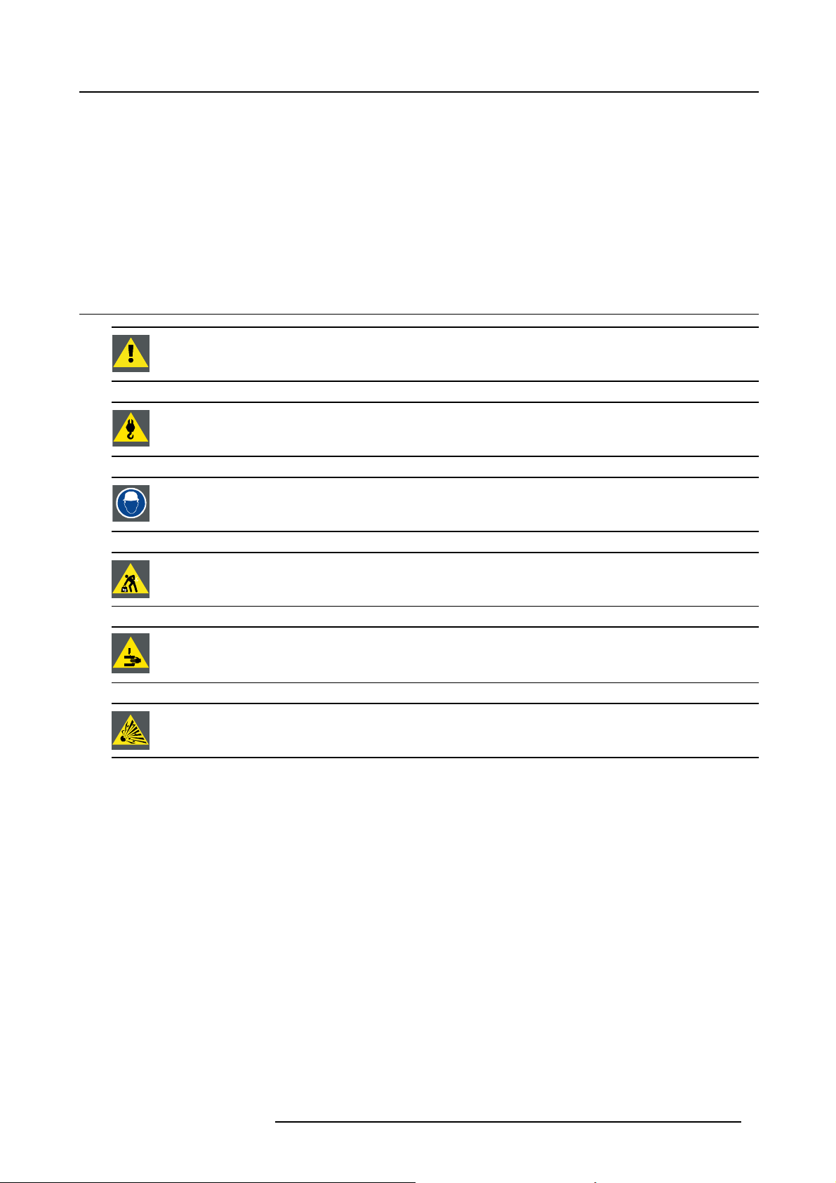
WARNING: Ensure you understand and follow all the safety guidelines, safety instructions, warnings and
cautions mentioned in this manual.
WARNING: Be aware of suspended loads.
1. Safety
WARNING: Wear a hard hat to reduce the risk of personal injury.
WARNING: Be careful while working with heavy loads.
WARNING: Mind your fingers while working with heavy loads.
CAUTION: High pressure lamp may explode if improperly handled.
General safety instructions
• Before operating this equipment please read this manual thoroughly and retain it for future reference.
• Installation and preliminary adjustments should be performed by qualified Barco personnel or by authorized Barco service deal-
ers.
• All warnings on the projector and in the documen
• All instructions for operating and use of this equipment must be followed precisely.
• All local installation codes should be adhered to.
tation manuals should be adhered to.
Notice on safety
This equipment is built in accordance with the requirements of the international safety standards IEC60950-1, EN60950-1,
UL60950-1 and CAN/CSA C22.2 No.60950-1, which are the safety standards of information technology equipment including
electrical business equipment. These safety standards impose important requirements on the use of safety critical components,
materials and insulation, in order to protect the user or operator against risk of electric shock and energy hazard and having access
to live parts. Safety standards also impose limits to the internal and external temperature rises, radiation levels, mechanical stability
and strength, enclosure construction and protection against the risk of fi re. Simulated single fault condition testing ensures the
safety of the equipment to the user even when the equipment’s normal operation fails.
Users definition
Throughout this manual, the term S
necessary to be knowledgeable of potential hazards to which they are exposed (including, but not limited to HIGH VOLTAGE ELECTRIC and ELECTRONIC CIRCUITRY and HIGH BRIGHTNESS PROJECTORS) in performing a task, and of measures to minimize
R5905032 HDX SERIES 05/12/2014 7
ERVICE PERSONNEL refers to persons having appropriate technical training and experience

1. Safety
the potential risk to themselves or other persons. The term USER and OPERATOR refers to any person other than SERVICE PERSONNEL, AUTHORIZED to operate professional projection systems.
A HDX projector is intended "FOR PROFESSIONAL USE ONLY" by AUTHORIZED PERSONNEL familiar with potential hazards
associated with high voltage, high intensity light beams, ultraviolet exposure and high temperatures generated by the lamp and
associated circuits. Only qualified SERVICE PERSONNEL, knowledgeable of such risks, are allowed to perform service functions
inside the product enclosure.
1.2 Important safety instructions
To prevent the risk of electrical shock
• This product should be operated from a mono phase AC power source.
• This apparatus must be grounded (earthed) via the supplied 3 conductor AC power cable. If none of the supplied power cables
are the correct one, consult your dealer.
If you are unable to insert the plug into the outlet, contact your electrician to replace your obsolete outlet. Do not defeat the
purpose of the grounding-type plug.
• Do not allow anything to rest on the power cord. Do not locate this product where persons will walk on the cord. To disconnect
the cord, pull it out by the plug. Never pull the cord itself.
• Use only the power cord supplied with your device. While appearing to be similar, other power cords have not been safety
tested at the factory and may not be used to power the device. For a replacement power cord, contact your dealer.
• Do not operate the projector with a damaged cord. Replace the cord.
Do not operate the projector if the projector has been dropped or damaged - until it has been examined and approved for
operation by a qualified service technician.
• Position the cord so that it will not be tripped over, pulled, or contact hot surfaces.
• If an extension cord is necessary, a cord with a current rating at least equ
for less amperage than the projector may overheat.
• Never push objects of any kind into this product through cabinet slots as they may touch dangerous voltage points or short out
parts that could result in a risk of fi re or electrical shock.
• Do not expose this projector to rain or moisture.
• Do not immerse or expose this projector in water or other liquids.
• Do not spill liquid of any kind on this projector.
• Should any liquid or solid object fall into the cabinet, unplug the set and have it checked by qualified service personnel before
resuming operations.
• Do not disassemble this projector, always take it to an authorized trained service person when service or repair work is required.
• Do not use an accessory attachment which is not recommended by the manufacturer.
• Lightning - For added protection for this video product during a lightning storm, or when it is left unattended and unused for long
periods of time, unplug it from the wall outlet. This will preven
t damage to the device due to lightning and AC power-line surges.
al to that of the projector should be used. A cord rated
To prevent personal injury
• Isolate electrically before replacing the lamp or lamp house. Caution: Hot lamp (house).
• Caution: High pressure lamp may explode if improperly handled. Refer servicing to qualified service personnel.
• To prevent injury and physical damage, always read this manual and all labels on the system before inserting the lamp casing,
connecting to the wall outlet or adjusting the projector.
• To prevent injury, take note of the weight of the projector. Minimum 4 persons are needed to carry the projector.
• To prevent injury, ensure that the lens and all covers are correctly installed. See installation procedures.
• Warning: high intensity light beam. NEVER look into the lens ! High luminance could result in damage to the eye.
• Warning: extremely high brightness lamps: This projector uses extr
directly into the lens or at the lamp. If the projection distance is less than 6 meter, any person needs to be at least 4 meters
away from the projected image. Avoid close range reflection of the projected image on any reflecting surface (such as glass,
metal, …) . When operating the projector, we strongly
• Before attempting to remove any of the projector’s covers, you must turn off the projector and disconnect from the wall outlet.
• When required to switch off the projector, to access parts inside, always disconnect the power cord from the power net.
• The power input at the projector side is considered as the disconnect device. When required to switch off the projector, to
access parts inside, always disconnect the power cord at the projector side. In case the power input at the projector side is not
accessible (e.g. ceiling mount), the socket outlet supplying the projector shall be installed nearby the projector and be easily
accessible, or a readily accessible general disconnect device shall be incorporated in the fixed wiring.
• Never stack more than two (2) HDX projectors in a hanging configuration (truss) and never stack more than three (3) HDX
projectors in a base stand configuration (table mount).
• When using the projector in a hanging configuration, always mount 2 safety cables. See installation manual for the correct use
of these cables.
• Do not place this equipment on an unstable cart, stand, or table. The product may fall, causing serious damage to it and
possible injury to the user.
8
recommend wearing suitable safety glasses.
emely high brightness lamps. Never attempt to look
R5905032 HDX SERIES 05/12/2014

1. Safety
• It is hazardous to operate without lens or shield. Lenses, shields or ultra violet screens shall be changed if they have become
visibly damaged to such an extent that their effectiveness is impaired. For example by cracks or deep scratches.
• Warning: Protection from ultraviolet radiation: Do not look directly in the light beam. The lamp contained in this product is
an intense source of light and heat. One component of the light emitted from this lamp is ultraviolet light. Potential eye and skin
hazards are present when the lamp is energized due to ultraviolet radiation. Avoid unnecessary exposure. Protect yourself and
your employees by making them aware of the hazards and how to protect themselves. Protecting the skin can be accomplished
by wearing tightly woven garments and gloves. Protecting the eyes from UV can be accomplished by wearing safety glasses
that are designed to provide UV protection. In addition to the UV, the visible light from the lamp is intense and should also be
considered when choosing protective eye wear.
• Exposure to UV radiation: Some medications are known to make individuals extra sensitive to UV radiation. The American
Conference of Governmental Industrial Hygienists (ACGIH) recommends occupational UV exposure for an-8 hour day to be
less than 0,1 micro-watts per square centimeters of effective UV radiation. An evaluation of the workplace is advised to assure
employees are not exposed to cumulative radiation levels exceeding these government guidelines. The exposer of this UV
radiation is allowed for only 1 hour per day for maintenance and service persons.
• Cooling liquid circuit. The projector contains a cooling circuit fi lled with Blue antifre
eze diluted (1/3 ethanediol – 2/3 Demi
water).
When the cooling circuit leaks, switch off the device and contact a service technician.
The liquid is not for household use. Keep out of reach of children. Harmful by oral intake. A
void exposure to pregnant women.
Avoid contact with eyes, skin and clothing. Avoid inhale of the noxious fumes.
• When the projector is mounted above persons, mount always a lens safety cable.
To prevent fire hazard
• Do not place flammable or combustible materials near the projector!
• Barco large screen projection products are designed and manufactured to meet the most stringent safety regulations. This
projector radiates heat on its external surfaces and from ventila
safe. Exposing flammable or combustible materials into close proximity of this projector could result in the spontaneous ignition
of that material, resulting in a fire. For this reason, it is absolutely necessary to leave an “exclusion zone” around all external
surfaces of the projector whereby no flammable or combustibl
40 cm (16”) for all DLP projectors. The exclusion zone on the lens side must be at least 5 m. Do not cover the projector or the
lens with any material while the projector is in operation. Keep flammable and combustible materials away from the projector at
all times. Mount the projector in a well ventilated area
away from sources of ignition and out of direct sun light. Never expose
the projector to rain or moisture. In the event of fire, use sand, CO
electrical fi re. Always have service performed on this projector by authorized Barco service personnel. Always insist on genuine
Barco replacement parts. Never use non-Barco repl
acement parts as they may degrade the safety of this projector.
• Slots and openings in this equipment are provided for ventilation. To ensure reliable operation of the projector and to protect
it from overheating, these openings must not be blocked or covered. The openings should never be blocked by placing the
projector too close to walls, or other similar surface. This projector should never be placed near or over a radiator or heat
register. This projector should not be placed in a built-in installation or enclosure unless proper ventilation is provided.
• Projection rooms must be well ventilated or cooled in order to avoid build up of heat.
• Let the projector cool down completely before storing. Remove cord from the projector when storing.
• Heat sensitive materials should not be placed in the path of the exhausted air or on the lamp house.
tion ducts during normal operation, which is both normal and
e materials are present. The exclusion zone must be not less than
or dry powder fire extinguishers. Never use water on an
2
To prevent projector damage
• This projector has been designed for use with a specific lamp (house) type. See installation instructions for its correct type.
• The air fi lters of the projector must be cleaned or replaced on regular base (a "clean" booth would be monthly-minimum).
Neglecting this could result in disrupting the air flow inside the projector, causing overheating. Overheating may lead to the
projector shutting down during operation.
• The projector must always be installed in a manner which ensures free flow of air into its air inlets and unimpeded evacuation
of the hot air from its cooling system.
• In order to ensure that correct airflow is maintained, and that the projector complies with Electromagnetic Compatibility (EMC)
requirements, it should always be operated with all of it’s covers in place.
• Slots and openings in the cabinet are provided for ventilation. To ensure reliable operation of the product and to protect it from
overheating, these openings must not be blocked or covered. The openings should never be blocked by placing the product
on a bed, sofa, rug, or other similar surface. This product should never be placed near or over a radiator or heat register. The
device should not be placed in a built-in installation or enclosure unless proper ventilation is provided.
• Ensure that nothing can be spilled on, or dropped inside the projector. If this does happen, switch off and unplug the mains
supply immediately. Do not operate the projector again until it has been checked by qualified service personnel.
• Do not block the projector cooling fans or free air movement around the projector. Loose papers or other objects may not be
nearer to the projector than 1
• Do not use this equipment near water.
• Special care for Laser Beams: Special care should be used when DLP projectors are used in the same room as high power
laser equipment. Direct or indirect hitting of a laser beam on to the lens can severely damage the Digital Mirror Devices
which case there is a loss of warranty.
• Never place the projector in direct sun light. Sun light on the lens can severely damage the Digital Mirror Devices
case there is a loss of warranty.
• Save the original shipping carton and packing material. They will come in handy if you ever have to ship your equipment. For
maximum protection, repack your set as it was originally packed at the factory.
0 cm (4") on any side.
TM
in which
TM
in
R5905032 HDX SERIES 05/12/2014
9

1. Safety
• Unplug this product from the wall outlet before cleaning. Do not use liquid cleaners or aerosol cleaners. Use a damp cloth for
cleaning. Never use strong solvents, such as thinner or benzine, or abrasive cleaners, since these will damage the cabinet.
Stubborn stains may be removed with a cloth lightly dampened with mild detergent solution.
• To ensure the highest optical performance and resolution, the projection lenses are specially treated with an anti-reflective
coating, therefore, avoid touching the lens. To remove dust on the lens, use a soft dry cloth. Do not use a damp cloth, detergent
solution, or thinner.
• Rated maximum ambient temperature, t
• The lamp house shall be replaced if it has become damaged or thermally deformed.
= 40 °C (104 °F).
a
On servicing
• Do not attempt to service this product yourself, as opening or removing covers may expose you to dangerous voltage potentials
and risk of electric shock.
• Refer all servicing to qualified service personnel.
• Attempts to alter the factory-set internal controls or to change other control settings not specially discussed in this manual can
lead to permanent damage to the projector and cancellation of the warranty.
• Unplug this product from the wall outlet and refer servicing to qualified service technicians under the following conditions:
- When the power cord or plug is damaged or frayed.
- If liquid has been spilled into the equipment.
- If the product has been exposed to rain or water.
- If the product does not operate normally when the operating instructions are followed. Adjust only those controls that are
covered by the operating instructions since improper adjustment of the other controls may result in damage and will often
require extensive work by a qualified technician to restore the product to normal operation.
- If the product has been dropped or the cabinet has been damaged.
- If the product exhibits a distinct change in performance, indicating a need for service.
• Replacement parts: When replacement parts are required, be sure the service technici
parts or authorized replacement parts which have the same characteristics as the Barco original part. Unauthorized substitutions may result in degraded performance and reliability, fire, electric shock or other hazards. Unauthorized substitutions may
void warranty.
• Safety check: Upon completion of any service or repairs to this projector, ask the service technician to perform safety checks
to determine that the product is in proper operating condition.
• Possible explosion hazard: Always keep in mind the caution below:
an has used original Barco replacement
CAUTION: Xenon compact arc lamps are highly pressurized. When ignited, the normal
of the bulb increases the pressure to a level at which the bulb may explode if not handled in strict accordance
to the manufacturer’s instructions. The bulb is stable at room temperature, but may still explode if dropped or
otherwise mishandled. Whenever the lamp house, containing a xenon lamp, has t
the protective container or cloth has to be removed from the xenon lamp, authorized protective clothing MUST
be worn!
operating temperature
o be dismantled or whenever
To prevent battery explosion
• Danger of explosion if battery is incorrectly installed.
• Replace only with the same or equivalent type recommended by the manufacturer.
• For disposal of used batteries, always consult federal, state, local and provincial hazardous waste disposal rules and regulations
to ensure proper disposal.
1.3 Important warnings concerning HDX flight cases
Important warnings concerning stacking/transporting HDX rental flight cases
• Stack maximum two (2) HDX rental flight cases high. Never higher.
• Surface on which flight case is standing must be level to ensure that the total load is evenly spread out among the four wheels.
The surface must also be able to support the load safely.
• Before stacking or transporting flight cases, check the wheels and their fixation screws for wear or defects.
• Before stacking or transporting flight cases, check that the four lock handles on each fl ight case are in good working order and
locked securely.
• When stacked, make sure the wheels of the upper fl ight case are precisely positioned in the stacking dishes of the flight case
below.
•Stackedflight cases may not be moved. Before stacking, the lower flight case must already be in its final resting position before
placing the second upon it.
• Never stack loaded flight cases in a truck or other transport medium, unless each flight case is rigidly strapped tight.
• In the event of a wheel breaking, flight cases must be rigidly strapped tight to prevent a stack collapsing.
10
R5905032 HDX SERIES 05/12/2014

• Use an appropriate forklift to raise flight cases and take the necessary precautions to avoid personnel injury.
1. Safety
R5905032 HDX SERIES 05/12/2014
11

1. Safety
12 R5905032 HDX SERIES 05/12/2014
2. GENERAL
About this chapter
Read this chapter before installing your HDX projector. It contains important information concerning installation requirements for the
HDX projector, such as minimum and maximum allowed ambient temperature, humidity conditions, required safety area around the
installed projector, required power net, etc.
Furthermore, careful consideration of things such as image size, ambient light level, projector placement and type of screen to use
are critical to the optimum use of the projection system.
Overview
• Installation requirements
• Unpacking the projector
• Initial inspection
• HDX fl ight case
• Projector configurations
• Projector air inlets and outlets
• Free download of Projector Toolset
• Installation process overview
Barco provides a guarantee relating to perfect manufacturing as part of the legally stipulated terms of guarantee. Observing the specification mentioned in this chapter is critical for projector performance. Neglecting
this can result in loss of warranty.
2. General
2.1 Installation requirements
Environment conditions
Table below summarizes the physical environment in which the HDX projector m
Environment
Ambient Temperature
Humidity
Altitude
Let the projector acclimatize after unpacking. Neglecting this may result in a startup failure of the Light Processor Unit.
Operating Non-Operating
10 °C (50 °F) to 40 °C (104 °F) -15°C (5°F) to 60°C (140°F)
5% to 85% RH Non-condensed 5% to 95% RH Non-Condensed
-60 (-197Ft) to 3000m (9843Ft) -60 (-197Ft) to 10000m (32810Ft)
Cooling requirements
The projector is fan cooled and must be installed with sufficient space around the projector head, minimum 10 cm (4 inch) to ensure
sufficient air flow. It should be used in an area where the ambient temperature, as measured at the projector air inlet , does not
exceed +40°C (+104°F).
Clean air environment
A projector must always be mounted in a manner which ensures the free fl ow of clean air into the projectors ventilation inlets. For
installations in environments where the projector is subject to airborne contaminants such as that produced by smoke machines or
similar (these deposit a thin layer of greasy residue upon the projectors internal optics and imaging electronic surfaces, degrading
performance), then it is highly advisable and desirable to have this contamination removed prior to it reaching the projectors clean
air supply. Devices or structures to extract or shield contaminated air well away from the projector are a prerequisite, if this is not a
feasible solution then measures to relocate the projector to a clean air environment should be considered.
Only ever use the manufacturer’s recomme
use industrial strength cleaners on the projector’s optics as these will degrade optical coatings and damage sensitive optoelectronics
components. Failure to take suitable precautions to protect the projector from the effects of persistent and prolonged air contaminants will culminate in extensive an
be noneffective and impracticable. Damage of this nature is under no circumstances covered under the manufacturer’s warranty
and may deem the warranty null and void. In such a case the client shall be held solely responsible for all costs incurred during any
repair. It is the clients responsi
bility to ensure at all times that the projector is protected from the harmful effects of hostile airborne
nded cleaning kit which has been specifically designed for cleaning optical parts, never
d irreversible ingrained optical damage. At this stage cleaning of the internal optical units will
ay be safely operated or stored.
R5905032 HDX SERIES 05/12/2014
13
2. General
particles in the environment of the projector. The manufacturer reserves the right to refuse repair if a projector has been subject to
knowingly neglect, abandon or improper use.
Main Power requirements
The HDX projector operates from a nominal mono phase power net with a separate earth ground PE.
Power requirements : 110-130V/200-240 V, 15A, 50-60Hz
The power cord required to connect the projector with the power net is delivered with the projector.
Projector weight
Do not underestimate the weight of the HDX projector. The projector weights about ±50 kg (±111 lb.) without lens. Be sure that the
pedestal on which the projector has to be installed is capable of handling five (5) times the complete load of the system.
2.2 Unpacking the projector
What has to be done ?
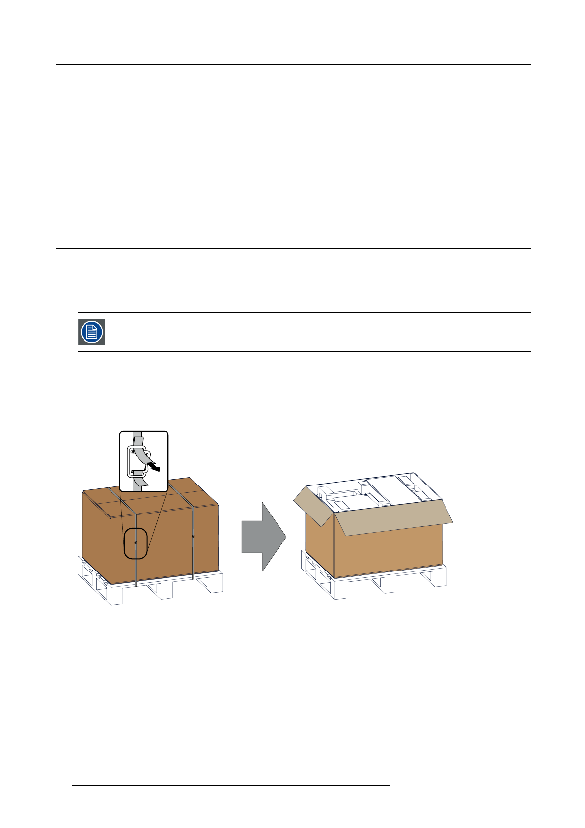
Upon delivery, the projector is packed in a carton box upon a wooden pallet and secured with banding and
thermore, to provide protection during transportation, the projector is surrounded with foam. Once the projector has arrived at the
installation site, it needs to be removed from the carton box and wooden pallet in a safe manner without damaging the projector.
After unpacking let the projector acclimatize to a room temperature higher then 10°C (50°F) and lower then
40°C (104°F). Neglecting this may result in a start up failure of the Light Processor Unit.
fastening clips. Fur-
Necessary tools
cutter knife
How to unpack
1. Remove the banding around the carton box, by releasing the fastening clips as illustrated, and open the box.
Image 2-1
Opening box
2. Remove the small box on top of the projector. This box contains the accessories such as manuals, remote control, etc.
14
R5905032 HDX SERIES 05/12/2014
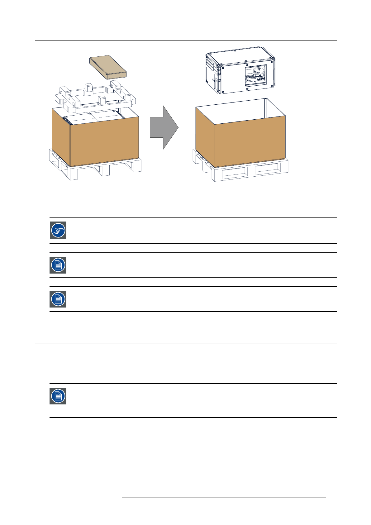
Image 2-2
Remove carton and foam rubber
3. Take out the foam rubber.
4. Take out the projector.
2. General
Save the original shipping carton and packing material, they will be necessary if you ever have to ship your
projector. For maximum protection, repack your projector as it was originally packed at the factory.
A rubber foam inside a plastic bag is placed into the lens opening of the projector. It’s recommended to reuse
this foam and plastic back each time you transport the projector. This to prevent intrusion of dust and foreign
particles.
The lens is delivered in a separate box.
2.3 Initial inspection
General
Before shipment, the projector was inspected and found to be free of mechanical and electrical defects. As soon as the projector is
unpacked, inspect for any damage that may have occurred in transit. Save all packing material until the inspection is completed. If
damage is found, file claim with carrier immediately. The Barco Sales and Service office should be notified as soon as possible.
The packaging of the HDX projector is provided with a shock-watch label. If this shock-watch label was triggered (red colored at arrival) during transport, that indicates that the package was possibly roughly handled
by the transport company. In this case, the instructions mentioned on the label, should be followed, which
are: adding a note on the “bill of lading” and informing the transportcompany and the Barco sales and service
office as soon as possible.
Box content
After unpacking the projector it is recommended to check if all following items where included:
• Three power cords of 2.5 meter, one CEE (7), one NEMA L6-20P and one CH2–16P
• This manual (installation manual).
• One Safety manual
• One remote control unit (RCU)
• Two AA size batteries for the RCU.
R5905032 HDX SERIES 05/12/2014
15
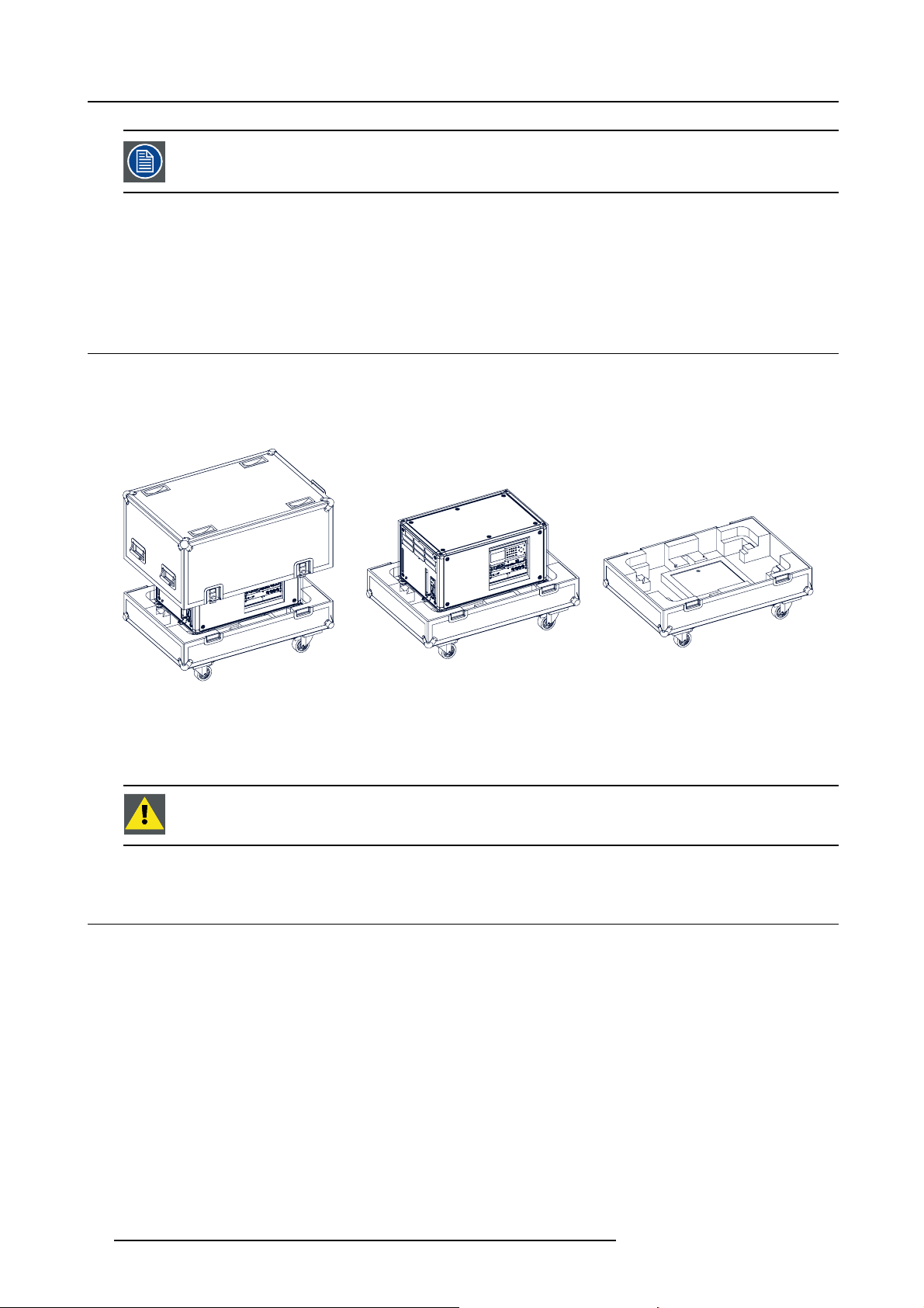
2. General
One xenon lamp is mounted inside the lamp house at delivery. The projector lenses are not included in the
package of the projector.
Mechanical check
This check should confirm that there are no broken knobs or connectors, that the cabinet and panel surfaces are free of dents and
scratches, and that the operating panel is not scratched or cracked. The Barco Sales and Service office should be notified as soon
as possible if this is not the case.
2.4 HDX flight case
Introduction of the HDX flight case
The HDX flight case is designed to transport the HDX projector in a safe and secure manner. The four caster wheels, provided with
breaks, and the four handles make the HDX flight case easy to handle. The floor of the flight case wagon is equipped with two small
covered compartments to store the remote control and the rigging clamps.
Image 2-3
HDX Flight case
Order number flight case: R9864090
The dimensions of the flight case are optimal for maximum utilization of the floor area of a truck. The cover of the HDX fl ight case
has 4 stacking dishes, which allows to stack the flight cases.
WARNING: Maximum stack two (2) HDX flight cases high. Never higher.
2.5 Projector configurations
The different configurations
Depending on the installation the projector can be mounted in different ways, the different configurations are:
1. Front / Table (F/T)
2. Front / Ceiling (F/C) (upside down)
3. Front / Ceiling (F/C) (table positio
4. Rear / Table (R/T)
5. Rear / Ceiling (R/C) (upside down)
6. Rear / Ceiling (R/C) (table position)
Front projection
The projector is installed, either in a table mount or ceiling mount configuration, at the same side of the screen as the audience.
n)
16
R5905032 HDX SERIES 05/12/2014
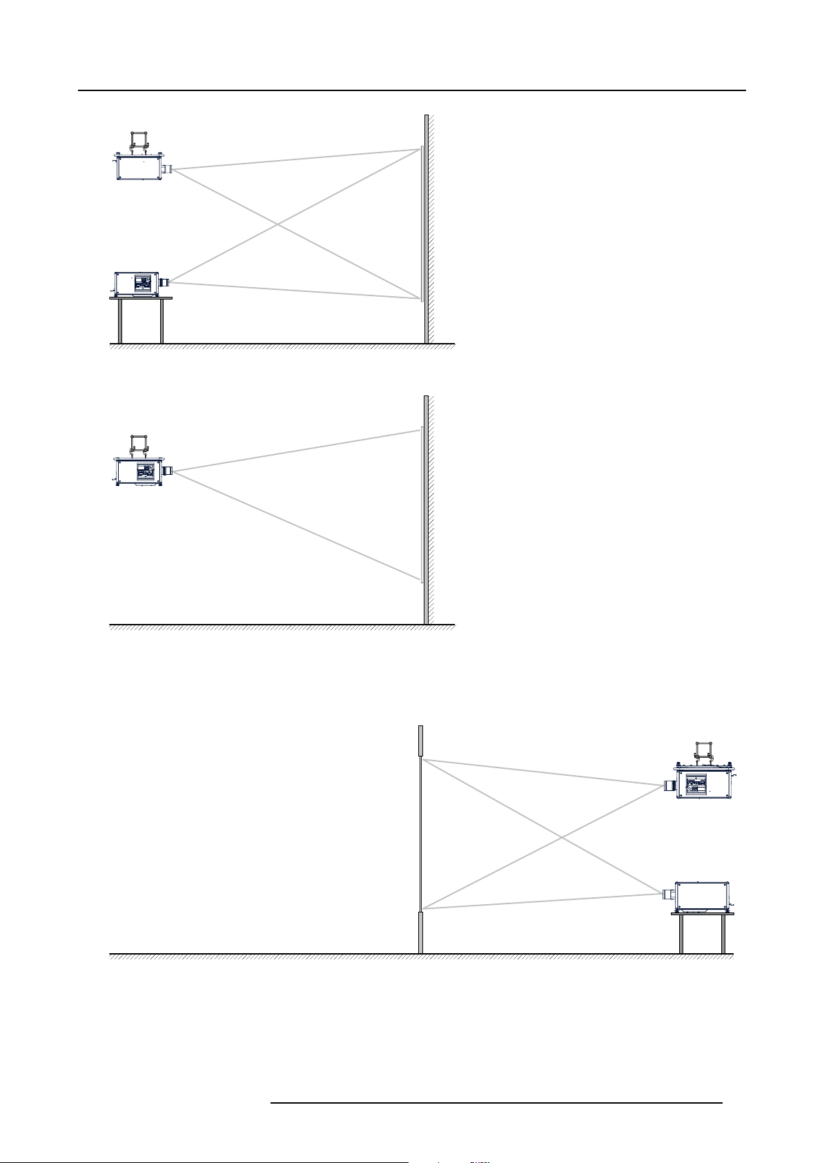
F/C
2. General
AUDIENCE
F/T
Image 2-4
Front projection
AUDIENCE
F/C
Image 2-5
Front proje ction, Ceiling mounted, in table position
SCREEN
FLOOR
SCREEN
FLOOR
Rear projection
The projector is installed, either in a table mount or ceiling mount configuration, at the other side of the screen opposite the audience.
AUDIENCE BACKSTAGE
R/C
R/T
Image 2-6
Rear projection
SCREEN
FLOOR
R5905032 HDX SERIES 05/12/2014 17
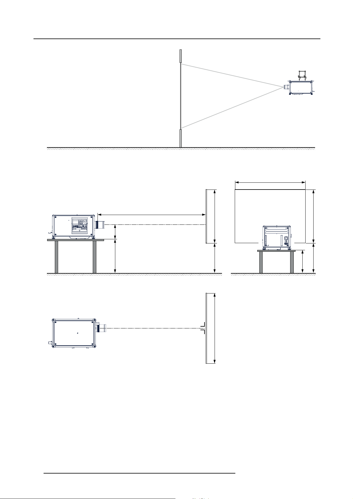
2. General
Image 2-7
Rear projection, ceiling mounted in table position
Positioning the projector
AUDIENCE BACKSTAGE
R/C
SCREEN
FLOOR
SW
PD
SCREENSCREEN
SHB
SHB
ACD
SCREEN
CD
FLOOR
SW
Image 2-8
Positioning proj ector
The projector should be installed at right angles (horizontally and vertically) to the screen at a distance PD. Note the distance (A)
between lens centre and table surface is slightly variable. This distance (A) is nominal 35 cm in case all feet are turned in completely
and the vertical lens shift is set to zero (0).
On axis / off axis projection
The position of the projector with reference to the screen may also be different depending on the installation. Basically the projector
can be positioned in On-Axis or Off-Axis configuration. On-Axis configuration means that the projector is positioned so as to have
the centre of the lens coinciding with the centre of the screen. Off-Axis projection is obtained by shifting the lens up, down, left or
right. Several parameters can be calculated determining the position in any installation.
Formula to calculate the distance CD for On-Axis projection: CD=SH/2+B-A
18
R5905032 HDX SERIES 05/12/2014
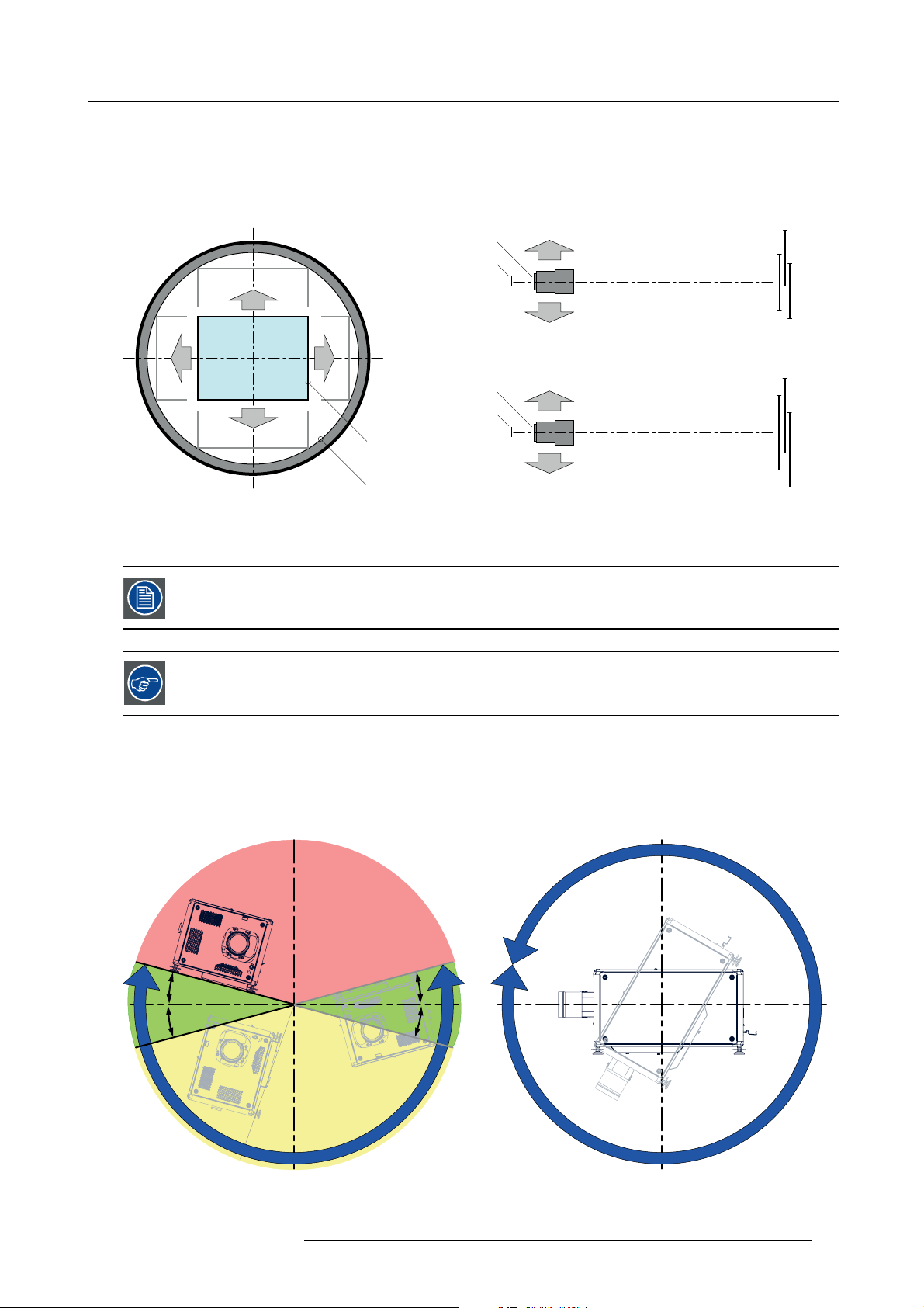
2. General
Shift range
The lens can be shifted with respect to the DMD (P) which result in a shifted image on the screen (Off-Axis). A 100% shift means that
the centre point of the projected image is shifted by half the screen size. In other words, the centre point of the projected image falls
together with the outline of the image in an On-Axis projection. Due to mechanical and optical limitations it’s recommended to keep
the shift values within the field of view (F) as illustrated below. Within these shift ranges the projector and lens perform excellently.
Configuring the projector outside these shift ranges will result in a slight decline of image quality.
U
-50% +50%
L R
D
Image 2-9
Vertical and horizontal shift range
PDMD.
F Field of view.
It is mechanical possible to shift outside the recommended field of view, but it will result in a decline of image
quality depending on the used lens and the zoom position of the used lens. Furthermore, shifting too much
in both directions will result in a blurred image corner.
Best image quality is projected in the On-Axis configuration.
+120%
-20%
F
P
F
P
P
F
U
D
L
R
SIDE VIEW
TOP VIEW
+120%
-20%
-50%
+50%
Horizontal and vertical projector tilt ranges
The projector can be rotated and mounted at any vertical angle. In other words, you can tilt the lens side of the projector as much
as desired for your application.
Side to side tilt, however, must not exceed ±15°. This limit ensures that the lamp in the projector operates properly and safely. More
tilting within area C is allowed but lamp flicker can happen.
B
MAX
15°
15°
A
A
15°
15°
MAX
360°
C
Image 2-10
A Tilting allowed without problems
B No tilting allowed in this area
R5905032 HDX SERIES 05/12/2014 19
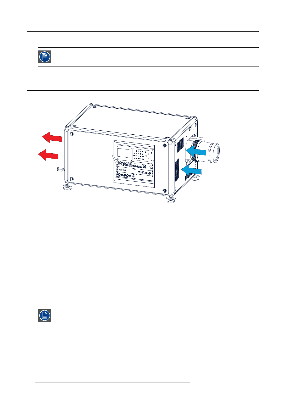
2. General
C Tilting allowed but lam p flicker possible
Projector lamp will not start up when out of tilt range due to build-in tilt sensor.
2.6 Projector air inlets and outlets
Air inlets and outlets
Image 2-11
The HDX projector has 3 air inlet channels and 3 air outlets. The air outlets are located at the rear of the projector. The air inlets
are located at the front of the projector.
2.7 Free download of Projector Toolset
About Projector Toolset
Projector Toolset is a software tool to set up, configure, manage and control Barco projectors.
The concept of this Projector Toolset software is modular. The basic package can be extended with several optional device plug-in
modules, now and in the future available.
The Projector Toolset software works wi
taken. A snapshot represents a current state of a configuration and can be reloaded to return to this typical state. These terms will
be used through the complete software.
Projector Toolset is a stand-alone application that runs on a Java Virtual Machine and that does not require extra services to run.
Several configurations can be controlled simultaneously. Even when the configurations are connected via different ways.
Projector Toolset is only availa
Where to find the download file(s)
The program and all necessary plug-ins, as well as the Reference manual can be downloaded for free from my.barco.com. Registration is necessary.
th configurations that can be loaded. Within a configuration, different snapshots can be
ble in a download version, no CD can be ordered.
20
R5905032 HDX SERIES 05/12/2014

1. Go to my.barco.com on https:\\my.barco.com.
2. Login on my.barco.com.
If you are not yet registered click on Sign up for my.barco.com and follow the instructions. With the created login and pass-
word, it is possible to enter the my.barco.com.
When your login is correct, the my.barco.com start page is displayed.
3. Click the Support tab and follow the wizard to find your projector. The Projector Toolset is located under the tab Application
Software.
4. Download the Projector Toolset software package, which includes the device plug-in updates as well as the corresponding
reference manual.
When downloading the complete Projector Toolset, this software contains already the latest device plug-ins. When you already have
the latest core version of Projector Toolset, it is possible to download only device plug-in updates from the same web site location.
As Projector Toolset is a stand alone application, it is not necessary to install any other software. A Java virtual machine is included
with this download.
Installation
Download first the reference manual (Part number: R59770052) and follow the installation instructions as written in this manual.
2.8 Installation process overview
Quick setup
The following steps describe briefly how to setup your HDX projector in a table mount front projection. Note that each step refers to
a corresponding procedure, which is more detailed and illustrated.
1. Install the batteries of the remote control. See "RCU battery installation", page 23
2. Place the projector on a solid table in front of the screen at the expected throw distance. Ensure that the projector is installed at
right angles (horizontally and vertically) with the screen. See "Projector configurations", page 16.
3. Select and install an appropriate lens, which covers the throw ratio ( = screen size / projector screen distance). See "Lenses",
page 27.
4. Connect the projector with the local power net. See "Connecting the projector with the power net", page 38.
5. Connect your source to the appropriate input module. See "Input source connections", page 48.
6. Switch ON the projector. See "Power on projector", page 57.
7. Select the input slot to which the source is connected. Do this by pressing the numeric key on the remote control unit or on the
local keypad, See "Source selection", page 63.
8. Zoom and shift the lens until the image is properly projected on the screen, Do this by using the “ZOOM” and “FOCUS” key on
the remote control unit or on the local keypad. If necessary, level the projector from side to side by turning the adjustable feet in
or out.
2. General
Check cooling liquid level at least every 6 months.
Every 6 months at device power up a message will be displayed on the local LCD to check the cooling liquid
level
R5905032 HDX SERIES 05/12/2014 21

2. General
22 R5905032 HDX SERIES 05/12/2014
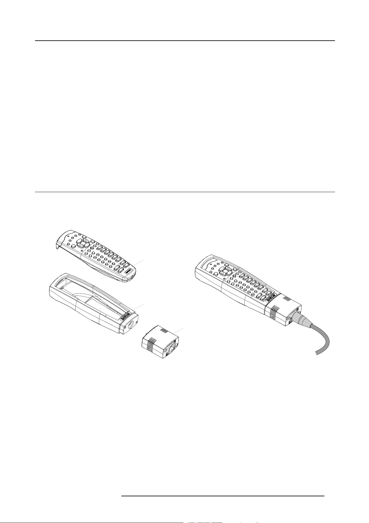
3. Physical installation
3. PHYSICAL INSTALLATION
About this projector
This chapter describes how the mechanical set up of the projector has to be done and how to realize the electrical connections.
Overview
• Remote control unit (RCU)
• Lenses
• Connecting the projector with the power net
• Alignment of a table mounted projector
• Mounting the bottom carry handler
• Mounting the top carry handler
• Suspension of the projector with rigging clamps
• Alignment of a ceiling mounted projector
3.1 Remote control unit (RCU)
Introduction
The remote control unit (A) of the HDX projector is equipped with a rugged case (B) and an XLR adaptor (C). The remote control
unit can be used wired via mini-jack or via rugged XLR. Note that the backlight, of the remote control unit, illuminate continuously
when wire connected.
Image 3-1
A Remote control unit (RCU).
B Rugged case.
C XLR adaptor.
Overview
• RCU battery installation
• RCU rugged case installation
• RCU XLR adaptor installation
• Using the XLR adaptor of the RCU
• RCU usage possibilities
A
B
C
3.1.1 RCU battery installation
Where to find the batteries for the remote control ?
The batteries are not placed in the remote control unit to avoid control operation in its package, resulting in a shorter battery life
time. At delivery the batteries can be found in a separated bag attached to the remote control unit. Before using your remote control,
install the batteries fi rst.
R5905032 HDX SERIES 05/12/2014
23

3. Physical installation
How to install the batteries in the remote control ?
1. Push the battery cover tab with the fingernail a little backwards (1) and pull, at the same time, the cover upwards (2).
1
Image 3-2
2. Insert the two AA size batteries, making sure the polarities match the + and - marks inside the battery compartment.
+
-
Image 3-3
3. Insert (1) the lower tab of the battery cover in the gap at the bottom of the remote control, and press (2) the cover until it clicks
in place.
+
-
2
2
+
+
Image 3-4
CAUTION: Replace with the correct battery type. Use two AA size batteries. There is a risk of explosion if the
battery is replaced with an incorrect type.
CAUTION: Replace the battery as explained above. There is a risk of explosion if the battery is incorrectly
installed.
3.1.2 RCU rugged case installation
How to install the rugged case of the remote control ?
1. Slide the bottom of the RCU into
1
-
the rugged case and then pull the top of the rugged case over the top of the RCU as illustrated.
24
R5905032 HDX SERIES 05/12/2014
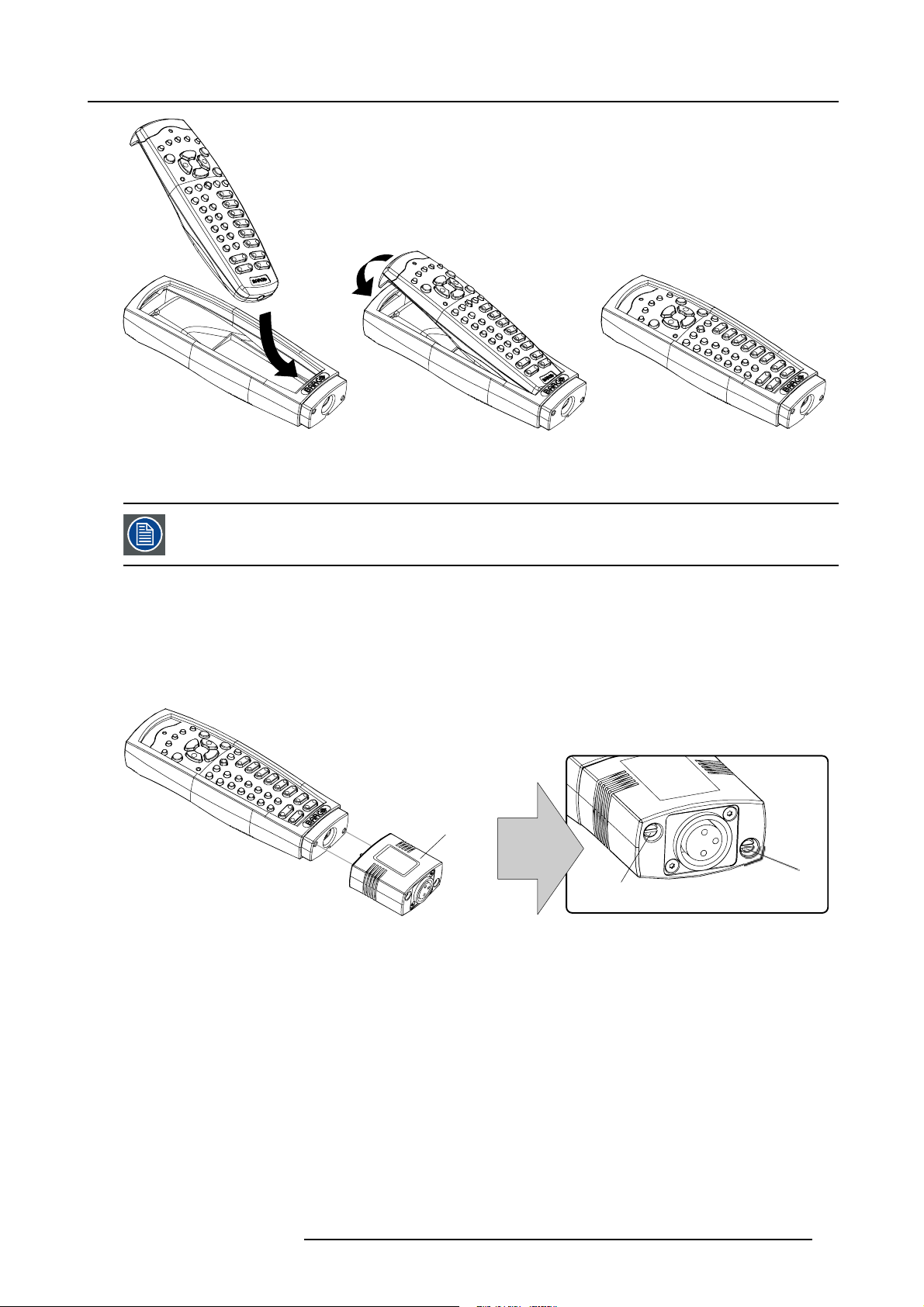
Image 3-5
3.1.3 RCU XLR adaptor installation
Install the rugged case before installing the XLR adaptor. Vice-versa, remove the XLR adaptor before removing
the rugged case from the RCU.
3. Physical installation
Necessary tools
5mmflat screw driver.
How to install the XLR adaptor of the remote control unit ?
1. Push the XLR adaptor (C) upon the rugged case of the remote control unit as illustrated.
Note: Ensure that the text of the XLR adaptor is on top.
C
S
Image 3-6
2. Fasten the two screws (S) of the XLR adaptor. Turn each screw repeatedly one or two turns until both screws are tight.
3.1.4 Using the XLR adaptor of the RCU
How to use the XLR adaptor of the remote control unit ?
1. Connect a cable with XLR plug into the XLR adaptor.
2. Connect the other end of the cable with your HDX projector.
3. Push the XLR adaptor completely a
wired communication. Pull out the XLR adaptor (about 8 mm) to switch over to wireless communication.
gainst the rugged case of the remote control unit, as illustrated in the left image below, for
S
R5905032 HDX SERIES 05/12/2014
25
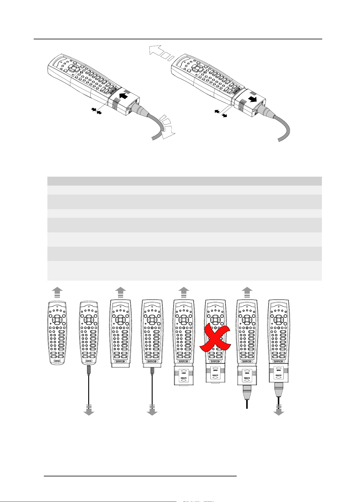
3. Physical installation
Image 3-7
3.1.5 RCU usage possibilities
Summarized possibilities
Ref. Possibility description Comment
a.
RCU not wired
b. RCU wired (mini-jack) Backlight illuminates continuously when wire is connected. Infra red
c.
RCU with rugged case not wired
d.
RCU with rugged case wired (mini-jack) Backlight illuminates continuously when wire is connected. Infra red
e.
RCU with rugged case and XLR adaptor
pulled out “REMOTE” and not wired
f. RCU with rugged case and XLR adaptor
pulled out “REMOTE” and wired
g.
RCU with rugged case and XLR adaptor
pushed in “WIRED” and wired
disabled.
disabled.
The XLR adaptor must be in the pulled out position “REMOTE”, otherwise
the RCU will not function.
The RCU will send the commands via infra red to the projector.
The RCU will send the commands via the cable connected with the XLR
adaptor to the projector. Backlight illuminates continuously when wire
is connected. Infra red disabled.
abcd fge
Image 3-8
26 R5905032 HDX SERIES 05/12/2014
 Loading...