


DP-2000
Installation manual
Barco Inc. Media and Entertainment Division
11101 Trade Center Drive, Rancho Cordova, California 95670, USA Phone: +1 916 859-2500
Fax: +1 916 859-2515
E-mail: folsomsales@barco.com Visit us at the web: www.barco.com
Barco nv Media & Entertainment Division Noordlaan 5, B-8520 Kuurne
Phone: +32 56.36.89.70
Fax: +32 56.36.883.86
E-mail: sales.events@barco.com Visit us at the web: www.barco.com
Printed in Belgium
Changes
Barco provides this manual ’as is’ without warranty of any kind, either expressed or implied, including but not limited to the implied warranties or merchantability and fitness for a particular purpose. Barco may make improvements and/or changes to the product(s) and/or the program(s) described in this publication at any time without notice.
This publication could contain technical inaccuracies or typographical errors. Changes are periodically made to the information in this publication; these changes are incorporated in new editions of this publication.
Federal Communications Commission (FCC Statement)
This equipment has been tested and found to comply with the limits for a class A digital device, pursuant to Part 15 of the FCC rules. These limits are designed to provide reasonable protection against harmful interference when the equipment is operated in a commercial environment. This equipment generates, uses, and can radiate radio frequency energy and, if not installed and used in accordance with the instruction manual, may cause harmful interference to radio communications. Operation of this equipment in a residential area may cause harmful interference, in which case the user will be responsible for correcting any interference at his own expense
EN55022/CISPR22 Class A ITE (Information Technology Equipment)
Class A ITE is a category of all other ITE which satisfies the class A ITE limits but not the class B ITE limits. Such equipment should not be restricted in its sale but the following warning shall be included in the instructions for use:
Warning : This is a class A product. In a domestic environment this product may cause radio interference in which case the user may be required to take adequate measures.
Guarantee and Compensation
Barco provides a guarantee relating to perfect manufacturing as part of the legally stipulated terms of guarantee. On receipt, the purchaser must immediately inspect all delivered goods for damage incurred during transport, as well as for material and manufacturing faults Barco must be informed immediately in writing of any complaints.
The period of guarantee begins on the date of transfer of risks, in the case of special systems and software on the date of commissioning, at latest 30 days after the transfer of risks. In the event of justified notice of complaint, Barco can repair the fault or provide a replacement at its own discretion within an appropriate period. If this measure proves to be impossible or unsuccessful, the purchaser can demand a reduction in the purchase price or cancellation of the contract. All other claims, in particular those relating to compensation for direct or indirect damage, and also damage attributed to the operation of software as well as to other services provided by Barco, being a component of the system or independent service, will be deemed invalid provided the damage is not proven to be attributed to the absence of properties guaranteed in writing or due to the intent or gross negligence or part of Barco.
If the purchaser or a third party carries out modifications or repairs on goods delivered by Barco, or if the goods are handled incorrectly, in particular if the systems are commissioned operated incorrectly or if, after the transfer of risks, the goods are subject to influences not agreed upon in the contract, all guarantee claims of the purchaser will be rendered invalid. Not included in the guarantee coverage are system failures which are attributed to programs or special electronic circuitry provided by the purchaser, e.g. interfaces. Normal wear as well as normal maintenance are not subject to the guarantee provided by Barco either.
The environmental conditions as well as the servicing and maintenance regulations specified in the this manual must be complied with by the customer.
Software License Agreement
You should carefully read the following terms and conditions before using this software. Your use of this software indicates your acceptance of this license agreement and warranty.
Terms and Conditions:
1.No redistribution of the software is allowed.
2.Reverse-Engineering. You may not reverse engineer, decompile, disassemble or alter anyhow this software product.
Disclaimer of Warranty:
This software and the accompanying files are sold “as is” and without warranties as to performance or merchantability or any other warranties whether expressed or implied. In no event shall Barco be liable for damage of any kind, loss of data, loss of profits, business interruption or other pecuniary loss arising directly or indirectly. Any liability of the seller will be exclusively limited to replacement of the product or refund of purchase price.
GNU-GPL code
If you would like a copy of the GPL source code contained in this product shipped to you on CD, please contact Barco. The cost of preparing and mailing a CD will be charged.

Disposal Information
This equipment has required the extraction and use of natural resources for its production. It may contain hazardous substances for health and environment. In order to avoid the dissemination of those substances in the environment and to diminish the pressure on natural resources, we encourage you to use the appropriate take-back systems. Those systems will reuse or recycle most of the materials of your end of life equipment in a sound way.
The crossed-out wheeled bin symbol invites you to use those systems. If you need more information on the collection, reuse and recycling systems, please contact your local or regional waste administrator. You can also contact us for more information on the environmental performances of our products.
Trademarks
Brand and product names mentioned in this manual may be trademarks, registered trademarks or copyrights of their respective holders. All brand and product names mentioned in this manual serve as comments or examples and are not to be understood as advertising for the products or their manufactures.
Copyright ©
All rights reserved. No part of this document may be copied, reproduced or translated. It shall not otherwise be recorded, transmitted or stored in a retrieval system without the prior written consent of Barco.

Table of contents
TABLE OF CONTENTS
1. Operating conditions .............................................................................................. 3
1.1 Certification . . . . . . . . . . . . . . . . . . . . . . . . . . . . . . . . . . . . . . . . . . . . . . . . . . . . . . . . . . . . . . . . . . . . . . . . . . . . . . . . . . . . . . . . . . . . . . . . . . . . . . . . . . . . . . . . . . . . . . . . .. . 4 1.2 Physical Environment . . . . . . . . . . . . . . . . . . . . . . . . . . . . . . . . . . . . . . . . . . . . . . . . . . . . . . . . . . . . . . . . . . . . . . . . . . . . . . . . . . . . . . . . . . . . . . . . . . . . . . . . . . . . . . . . 5 1.3 Heat Dissipation/Cooling . . . . . . . . . . . . . . . . . . . . . . . . . . . . . . . . . . . . . . . . . . . . . . . . . . . . . . . . . . . . . . . . . . . . . . . . . . . . . . . . . . . . . . . . . . . . . . . . . . . . .. . . . . . . . 6 1.4 Input Power . .. . . . . . . . . . . . . . . . . . . . . . . . . . . . . . . . . . . . . . . . . . . . . . . . . . . . . . . . . . . . . . . . . . . . . . . . . . . . . . . . . . . . . . . . . . . . . . . . . . . . . . . . . . . . . . . . . . . . . . . . . 7 1.5 Initial Inspection . . . . . . . . . . . . . . . . . . . . . . . . . . . . . . . . . . . . . . . . . . . . . . . . . . . . . . . . . . . . . . . . . . . . . . . . . . . . . . . . . . . . . . . . . . . . . . . . . . . . . . . . . . .. . . . . . . . . . . 8 1.6 Mutual Agreement . . . . . . . . . . . . . . . . . . . . . . . . . . . . . . . . . . . . . . . . . . . . . . . . . . . . . . . . . . . . . . . . . . . . . . . . . . . . . . . . . . . . . . . . . . . . . . . . . . . . . . . . . . . . .. . . . . . . 9
2. Safety instructions ................................................................................................ 11
2.1 General considerations. . . . . . . . . . . . . . . . . . . . . . . . . . . . . . . . . . . . . . . . . . . . . . . . . . . . . . . . . . . . . . . . . . . . . . . . . . . . . . . . . . . . . . . . . . . . . . . . . . . . . . . . . . . . . . 12 2.2 Restricted Access Location . . . . . . . . . . . . . . . . . . . . . . . . . . . . . . . . . . . . . . . . . . . . . . . . . . . . . . . . . . . . . . . . . . . . . . . . . . . . . . . . . . . . . . . . . . . . . . . . . . . .. . . . . 13 2.3 Electrical Safety . . . . . . . . . . . . . . . . . . . . . . . . . . . . . . . . . . . . . . . . . . . . . . . . . . . . . . . . . . . . . . . . . . . . . . . . . . . . . . . . . . . . . . . . . . . . . . . . . . . . . . . . . . . .. . . . . . . . . 14 2.4 Heat and Fire Hazards . . . . . . . . . . . . . . . . . . . . . . . . . . . . . . . . . . . . . . . . . . . . . . . . . . . . . . . . . . . . . . . . . . . . . . . . . . . . . . . . . . . . . . . . . . . . . . . . . . . . . . . . . .. . . . 15 2.5 Safety on Installation . . . . . . . . . . . . . . . . . . . . . . . . . . . . . . . . . . . . . . . . . . . . . . . . . . . . . . . . . . . . . . . . . . . . . . . . . . . . . . . . . . . . . . . . . . . . . . . . . . . . . . . .. . . . . . . . 16 2.6 Protection from Ultraviolet Radiation. . . . . . . . . . . . . . . . . . . . . . . . . . . . . . . . . . . . . . . . . . . . . . . . . . . . . . . . . . . . . . . . . . . . . . . . . . . . . . . . . . . . . . . . . .. . . . . . 17 2.7 Protection on Servicing. . . . . . . . . . . . . . . . . . . . . . . . . . . . . . . . . . . . . . . . . . . . . . . . . . . . . . . . . . . . . . . . . . . . . . . . . . . . . . . . . . . . . . . . . . . . . . . . . . . . . . .. . . . . . . 18 2.8 Safety on Cleaning .. . . . . . . . . . . . . . . . . . . . . . . . . . . . . . . . . . . . . . . . . . . . . . . . . . . . . . . . . . . . . . . . . . . . . . . . . . . . . . . . . . . . . . . . . . . . . . . . . . . . . . . . . . . . . . . . . 19 2.9 Safety on Shipping . . . . . . . . . . . . . . . . . . . . . . . . . . . . . . . . . . . . . . . . . . . . . . . . . . . . . . . . . . . . . . . . . . . . . . . . . . . . . . . . . . . . . . . . . . . . . . . . . . . . . . . . . . . .. . . . . . 20
3. Mechanical set up of the DP-2000 ..............................................................................21
3.1 Unpacking the projector . . . . . . . . . . . . . . . . . . . . . . . . . . . . . . . . . . . . . . . . . . . . . . . . . . . . . . . . . . . . . . . . . . . . . . . . . . . . . . . . . . . . . . . . . . . . . . . . . . . . . . . . . . . . . 22 3.2 Positioning the DP-2000 at port window . . . . . . . . . . . . . . . . . . . . . . . . . . . . . . . . . . . . . . . . . . . . . . . . . . . . . . . . . . . . . . . . . . . . . . . . . . . . . . . . . . . . . . . . . . . . 24
3.3Installation of the exhaust system.. . . . . . . . . . . . . . . . . . . . . . . . . . . . . . . . . . . . . . . . . . . . . . . . . . . . . . . . . . . . . . . . . . . . . . . . . . . . . . . . . . . . . . . . . . . . . . . . . . 27
4. Electrical set up of the DP-2000 ................................................................................29
4.1 Power requirements . . . . . . . . . . . . . . . . . . . . . . . . . . . . . . . . . . . . . . . . . . . . . . . . . . . . . . . . . . . . . . . . . . . . . . . . . . . . . . . . . . . . . . . . . . . . . . . . . . . . . . . . . . . . . . . . . 30 4.2 Connecting the main AC power . . .. . . . . . . . . . . . . . . . . . . . . . . . . . . . . . . . . . . . . . . . . . . . . . . . . . . . . . . . . . . . . . . . . . . . . . . . . . . . . . . . . . . . . . . . . . . . . . . . . . 31
5. Lenses & lens holder .............................................................................................33
5.1 Available lenses . . . . . . . . . . . . . . . . . . . . . . . . . . . . . . . . . . . . . . . . . . . . . . . . . . . . . . . . . . . . . . . . . . . . . . . . . . . . . . . . . . . . . . . . . . . . . . . . . . . . . . . . . . . . .. . . . . . . . 34 5.2 Lens selection . . . . . . . . . . . . . . . . . . . . . . . . . . . . . . . . . . . . . . . . . . . . . . . . . . . . . . . . . . . . . . . . . . . . . . . . . . . . . . . . . . . . . . . . . . . . . . . . . . . . . . . . . . . . . . . . . . . . . . . 35 5.3 Lens formulas. . . . . . . . . . . . . . . . . . . . . . . . . . . . . . . . . . . . . . . . . . . . . . . . . . . . . . . . . . . . . . . . . . . . . . . . . . . . . . . . . . . . . . . . . . . . . . . . . . . . . . . . . . . . . . . . . . . . . . . . 36 5.4 Lens removal . . . . . . . . . . . . . . . . . . . . . . . . . . . . . . . . . . . . . . . . . . . . . . . . . . . . . . . . . . . . . . . . . . . . . . . . . . . . . . . . . . . . . . . . . . . . . . . . . . . . . . . . . . . . . . . . . . . . . . . . 37 5.5 Lens installation . . . . . . . . . . . . . . . . . . . . . . . . . . . . . . . . . . . . . . . . . . . . . . . . . . . . . . . . . . . . . . . . . . . . . . . . . . . . . . . . . . . . . . . . . . . . . . . . . . . . . . . . . . . . . . . . . . . . . 38 5.6 Lens shift, zoom & focus . . .. . . . . . . . . . . . . . . . . . . . . . . . . . . . . . . . . . . . . . . . . . . . . . . . . . . . . . . . . . . . . . . . . . . . . . . . . . . . . . . . . . . . . . . . . . . . . . . . . . . . . . . . . 40 5.7 Scheimpflug adjustment. . . . . . . . . . . . . . . . . . . . . . . . . . . . . . . . . . . . . . . . . . . . . . . . . . . . . . . . . . . . . . . . . . . . . . . . . . . . . . . . . . . . . . . . . . . . . . . . . . . . . . . . . . . . . 41
6. Lamp & lamp house...............................................................................................45
6.1 Introduction . . . . . . . . . . . . . . . . . . . . . . . . . . . . . . . . . . . . . . . . . . . . . . . . . . . . . . . . . . . . . . . . . . . . . . . . . . . . . . . . . . . . . . . . . . . . . . . . . . . . . . . . . . . . . . . .. . . . . . . . . . 46 6.2 Removal of the lamp house . . . . . . . . . . . . . . . . . . . . . . . . . . . . . . . . . . . . . . . . . . . . . . . . . . . . . . . . . . . . . . . . . . . . . . . . . . . . . . . . . . . . . . . . . . . . . . . . . . . . . . . . . 47 6.3 Removal of the xenon bulb lamp. .. . . . . . . . . . . . . . . . . . . . . . . . . . . . . . . . . . . . . . . . . . . . . . . . . . . . . . . . . . . . . . . . . . . . . . . . . . . . . . . . . . . . . . . . . . . . . . . . . . 49 6.4 Installation of the xenon bulb lamp. . . . . . . . . . . . . . . . . . . . . . . . . . . . . . . . . . . . . . . . . . . . . . . . . . . . . . . . . . . . . . . . . . . . . . . . . . . . . . . . . . . . . . . . . . . . . . . . . . 52 6.5 Installation of the lamp house . . . . . . . . . . . . . . . . . . . . . . . . . . . . . . . . . . . . . . . . . . . . . . . . . . . . . . . . . . . . . . . . . . . . . . . . . . . . . . . . . . . . . . . . . . . . . . . . . . . . . . . 57 6.6 Resetting the lamp parameters . . .. . . . . . . . . . . . . . . . . . . . . . . . . . . . . . . . . . . . . . . . . . . . . . . . . . . . . . . . . . . . . . . . . . . . . . . . . . . . . . . . . . . . . . . . . . . . . . . . . . 59 6.7 Realignment of the lamp in its reflector . . . . . . . . . . . . . . . . . . . . . . . . . . . . . . . . . . . . . . . . . . . . . . . . . . . . . . . . . . . . . . . . . . . . . . . . . . . . . . . . . . . . . . . . . . . . . 60
7. Input & communication unit.....................................................................................63
7.1 Introduction . . . . . . . . . . . . . . . . . . . . . . . . . . . . . . . . . . . . . . . . . . . . . . . . . . . . . . . . . . . . . . . . . . . . . . . . . . . . . . . . . . . . . . . . . . . . . . . . . . . . . . . . . . . . . . . .. . . . . . . . . . 64 7.2 Local Keypad of the DP-2000 projector . . . . . . . . . . . . . . . . . . . . . . . . . . . . . . . . . . . . . . . . . . . . . . . . . . . . . . . . . . . . . . . . . . . . . . . . . . . . . . . . . . . . . . . . . . . . 65 7.3 Communication ports of the DP-2000 projector .. . . . . . . . . . . . . . . . . . . . . . . . . . . . . . . . . . . . . . . . . . . . . . . . . . . . . . . . . . . . . . . . . . . . . . . . . . . . . . . . . . . 66 7.4 About General Purpose Inputs & Outputs (GPIO). . . . . . . . . . . . . . . . . . . . . . . . . . . . . . . . . . . . . . . . . . . . . . . . . . . . . . . . . . . . . . . . . . . . . . . . . . . . . . . . . . 68 7.5 Source input ports of the DP-2000 projector . . . . . . . . . . . . . . . . . . . . . . . . . . . . . . . . . . . . . . . . . . . . . . . . . . . . . . . . . . . . . . . . . . . . . . . . . . . . . . . . . . . . . . . 70
8. Communicator touch panel......................................................................................71
8.1 Introduction . . . . . . . . . . . . . . . . . . . . . . . . . . . . . . . . . . . . . . . . . . . . . . . . . . . . . . . . . . . . . . . . . . . . . . . . . . . . . . . . . . . . . . . . . . . . . . . . . . . . . . . . . . . . . . . .. . . . . . . . . . 72 8.2 Installing the touch panel interface. . . . . . . . . . . . . . . . . . . . . . . . . . . . . . . . . . . . . . . . . . . . . . . . . . . . . . . . . . . . . . . . . . . . . . . . . . . . . . . . . . . . . . . . . . . .. . . . . . 74 8.3 Reposition the touch panel interface. . . . . . . . . . . . . . . . . . . . . . . . . . . . . . . . . . . . . . . . . . . . . . . . . . . . . . . . . . . . . . . . . . . . . . . . . . . . . . . . . . . . . . . . . . . . . . . . 76
9. Starting up..........................................................................................................77
9.1 Switching on the DP-2000 projector . . . . . . . . . . . . . . . . . . . . . . . . . . . . . . . . . . . . . . . . . . . . . . . . . . . . . . . . . . . . . . . . . . . . . . . . . . . . . . . . . . . . . . . . . . . . . .. . 78 9.2 Switching off the DP-2000 projector . . . . . . . . . . . . . . . . . . . . . . . . . . . . . . . . . . . . . . . . . . . . . . . . . . . . . . . . . . . . . . . . . . . . . . . . . . . . . . . . . . . . . . . . . . . . .. . . 79
10. Projector registration .............................................................................................81
10.1 Introduction . . . . . . . . . . . . . . . . . . . . . . . . . . . . . . . . . . . . . . . . . . . . . . . . . . . . . . . . . . . . . . . . . . . . . . . . . . . . . . . . . . . . . . . . . . . . . . . . . . . . . . . . . . . . . . .. . . . . . . . . . . 82 10.2 Download the certificate file . . . . . . . . . . . . . . . . . . . . . . . . . . . . . . . . . . . . . . . . . . . . . . . . . . . . . . . . . . . . . . . . . . . . . . . . . . . . . . . . . . . . . . . . . . . . . . . . . . . . . . . . . 83 10.3 Registration of new projector. . . . . . . . . . . . . . . . . . . . . . . . . . . . . . . . . . . . . . . . . . . . . . . . . . . . . . . . . . . . . . . . . . . . . . . . . . . . . . . . . . . . . . . . . . . . . . . . .. . . . . . . 84 10.4 Update registration of an existing projector. . . . . . . . . . . . . . . . . . . . . . . . . . . . . . . . . . . . . . . . . . . . . . . . . . . . . . . . . . . . . . . . . . . . . . . . . . . . . . . . . . . . . . . . . 90
11. Maintenance........................................................................................................91
11.1 Cleaning the lens . . .. . . . . . . . . . . . . . . . . . . . . . . . . . . . . . . . . . . . . . . . . . . . . . . . . . . . . . . . . . . . . . . . . . . . . . . . . . . . . . . . . . . . . . . . . . . . . . . . . . . . . . . . . . . . . . . . . 92 11.2 Cleaning the exterior of the projector . . . . . . . . . . . . . . . . . . . . . . . . . . . . . . . . . . . . . . . . . . . . . . . . . . . . . . . . . . . . . . . . . . . . . . . . . . . . . . . . . . . . . . . . . . . . . . . 93 11.3 Replacement of the dust filter on the front side . . . . . . . . . . . . . . . . . . . . . . . . . . . . . . . . . . . . . . . . . . . . . . . . . . . . . . . . . . . . . . . . . . . . . . . . . . . . . . . . . . . . 94 11.4 Replacement of the dust filter on the bottom side . . . . . . . . . . . . . . . . . . . . . . . . . . . . . . . . . . . . . . . . . . . . . . . . . . . . . . . . . . . . . . . . . . . . . . . . . . . . . . . . . . 96 11.5 Replacement of the dust filter on the top side . . . . . . . . . . . . . . . . . . . . . . . . . . . . . . . . . . . . . . . . . . . . . . . . . . . . . . . . . . . . . . . . . . . . . . . . . . . . . . . . . . . . . . 97
R59770071 DP-2000 06/01/2009 |
|
1 |

Table of contents
11.6 Pressure verification of the liquid cooling circuit. . . . . . . . . . . . . . . . . . . . . . . . . . . . . . . . . . . . . . . . . . . . . . . . . . . . . . . . . . . . . . . . . . . . . . . . . . . . . . . . . . . . 98
12. Servicing............................................................................................................99
12.1 Removal of the Input & Communication unit . . . . . . . . . . . . . . . . . . . . . . . . . . . . . . . . . . . . . . . . . . . . . . . . . . . . . . . . . . . . . . . . . . . . . . . . . . . . . . . . . . . . . .100 12.2 Installation of the Input & Communication unit . .. . . . . . . . . . . . . . . . . . . . . . . . . . . . . . . . . . . . . . . . . . . . . . . . . . . . . . . . . . . . . . . . . . . . . . . . . . . . . . . . . .101 12.3 Convergence (with extenders) . . . . . . . . . . . . . . . . . . . . . . . . . . . . . . . . . . . . . . . . . . . . . . . . . . . . . . . . . . . . . . . . . . . . . . . . . . . . . . . . . . . . . . . . . . . . . . . . . . . . .103 12.3.1 Convergence controls . . . . . . . . . . . . . . . . . . . . . . . . . . . . . . . . . . . . . . . . . . . . . . . . . . . . . . . . . . . . . . . . . . . . . . . . . . . . . . . . . . . . . . . . . . . . . . . . . . . . . . .104 12.3.2 Preparing for convergence adjustment. . . . . . . . . . . . . . . . . . . . . . . . . . . . . . . . . . . . . . . . . . . . . . . . . . . . . . . . . . . . . . . . . . . . . . . . . . . . . . . . . . . . . .106 12.3.3 Converging the red pattern onto the blue pattern. . . . . . . . . . . . . . . . . . . . . . . . . . . . . . . . . . . . . . . . . . . . . . . . . . . . . . . . . . . . . . . . . . . . . . . . . . .107 12.3.4 Converging the green pattern onto the blue pattern . . . . . . . . . . . . . . . . . . . . . . . . . . . . . . . . . . . . . . . . . . . . . . . . . . . . . . . . . . . . . . . . . . . . . . . .109 12.4 Convergence (old system) .. . . . . . . . . . . . . . . . . . . . . . . . . . . . . . . . . . . . . . . . . . . . . . . . . . . . . . . . . . . . . . . . . . . . . . . . . . . . . . . . . . . . . . . . . . . . . . . . . . . . . . . . 111 12.4.1 Action of the convergence controls. . . . . . . . . . . . . . . . . . . . . . . . . . . . . . . . . . . . . . . . . . . . . . . . . . . . . . . . . . . . . . . . . . . . . . . . . . . . . . . . . . . . . . . . . . 112 12.4.2 Re-converging Green on Blue. . . . . . . . . . . . . . . . . . . . . . . . . . . . . . . . . . . . . . . . . . . . . . . . . . . . . . . . . . . . . . . . . . . . . . . . . . . . . . . . . . . . . . . . . . . . . . . 113 12.4.3 Readjustment of the plungers . . . . . . . . . . . . . . . . . . . . . . . . . . . . . . . . . . . . . . . . . . . . . . . . . . . . . . . . . . . . . . . . . . . . . . . . . . . . . . . . . . . . . . . . . . . . . . . 116 12.4.4 Re-converging Red on Blue . . . . . . . . . . . . . . . . . . . . . . . . . . . . . . . . . . . . . . . . . . . . . . . . . . . . . . . . . . . . . . . . . . . . . . . . . . . . . . . . . . . . . . . . . . . . . . . . . 117 12.5 Authorization to clear security warning . . . . . . . . . . . . . . . . . . . . . . . . . . . . . . . . . . . . . . . . . . . . . . . . . . . . . . . . . . . . . . . . . . . . . . . . . . . . . . . . . . . . . . . . . . . .121
13. Removal and installation of projector covers .............................................................. 123
13.1 Removal of the lamp cover. . . . . . . . . . . . . . . . . . . . . . . . . . . . . . . . . . . . . . . . . . . . . . . . . . . . . . . . . . . . . . . . . . . . . . . . . . . . . . . . . . . . . . . . . . . . . . . . . . . . . .. . .124 13.2 Removal of the input cover.. . . . . . . . . . . . . . . . . . . . . . . . . . . . . . . . . . . . . . . . . . . . . . . . . . . . . . . . . . . . . . . . . . . . . . . . . . . . . . . . . . . . . . . . . . . . . . . . . . . . . . . .125 13.3 Removal of the front cover . . . . . . . . . . . . . . . . . . . . . . . . . . . . . . . . . . . . . . . . . . . . . . . . . . . . . . . . . . . . . . . . . . . . . . . . . . . . . . . . . . . . . . . . . . . . . . . . . . . . .. . . .126 13.4 Removal of the side cover. . . . . . . . . . . . . . . . . . . . . . . . . . . . . . . . . . . . . . . . . . . . . . . . . . . . . . . . . . . . . . . . . . . . . . . . . . . . . . . . . . . . . . . . . . . . . . . . . . . . . .. . . .127 13.5 Removal of the rear cover. . . . . . . . . . . . . . . . . . . . . . . . . . . . . . . . . . . . . . . . . . . . . . . . . . . . . . . . . . . . . . . . . . . . . . . . . . . . . . . . . . . . . . . . . . . . . . . . . . . . . .. . . .128 13.6 Removal of the top cover. . . . . . . . . . . . . . . . . . . . . . . . . . . . . . . . . . . . . . . . . . . . . . . . . . . . . . . . . . . . . . . . . . . . . . . . . . . . . . . . . . . . . . . . . . . . . . . . . . . . . . .. . . .129 13.7 Open the sealed compartment . . . . . . . . . . . . . . . . . . . . . . . . . . . . . . . . . . . . . . . . . . . . . . . . . . . . . . . . . . . . . . . . . . . . . . . . . . . . . . . . . . . . . . . . . . . . . . . . . . . . .130 13.8 Close the sealed compartment. . . . . . . . . . . . . . . . . . . . . . . . . . . . . . . . . . . . . . . . . . . . . . . . . . . . . . . . . . . . . . . . . . . . . . . . . . . . . . . . . . . . . . . . . . . . . . . . . .. . .131 13.9 Installation of the top cover. . . . . . . . . . . . . . . . . . . . . . . . . . . . . . . . . . . . . . . . . . . . . . . . . . . . . . . . . . . . . . . . . . . . . . . . . . . . . . . . . . . . . . . . . . . . . . . . . .. . . . . . .132 13.10 Installation of the rear cover. . . . . . . . . . . . . . . . . . . . . . . . . . . . . . . . . . . . . . . . . . . . . . . . . . . . . . . . . . . . . . . . . . . . . . . . . . . . . . . . . . . . . . . . . . . . . . . .. . . . . . . .133 13.11 Installation of the side cover . . . . . . . . . . . . . . . . . . . . . . . . . . . . . . . . . . . . . . . . . . . . . . . . . . . . . . . . . . . . . . . . . . . . . . . . . . . . . . . . . . . . . . . . . . . . . . . .. . . . . . .134 13.12 Installation of the front cover . . . . . . . . . . . . . . . . . . . . . . . . . . . . . . . . . . . . . . . . . . . . . . . . . . . . . . . . . . . . . . . . . . . . . . . . . . . . . . . . . . . . . . . . . . . . . . .. . . . . . . .135 13.13 Installation of the input cover. . . . . . . . . . . . . . . . . . . . . . . . . . . . . . . . . . . . . . . . . . . . . . . . . . . . . . . . . . . . . . . . . . . . . . . . . . . . . . . . . . . . . . . . . . . . . . . . . . . . . . .136 13.14 Installation of the lamp cover. . . . . . . . . . . . . . . . . . . . . . . . . . . . . . . . . . . . . . . . . . . . . . . . . . . . . . . . . . . . . . . . . . . . . . . . . . . . . . . . . . . . . . . . . . . . . . . .. . . . . . .137
A. Specifications ..................................................................................................... 139
A.1 Specifications of the DP-2000. . . . . . . . . . . . . . . . . . . . . . . . . . . . . . . . . . . . . . . . . . . . . . . . . . . . . . . . . . . . . . . . . . . . . . . . . . . . . . . . . . . . . . . . . . . . . . . . . . . . . .141
B. Dimensions ........................................................................................................ 143
B.1 Dimensions of the DP-2000 . . . . . . . . . . . . . . . . . . . . . . . . . . . . . . . . . . . . . . . . . . . . . . . . . . . . . . . . . . . . . . . . . . . . . . . . . . . . . . . . . . . . . . . . . . . . . . . . . . . . . . . .144 B.2 Centre of gravity of the DP-2000. .. . . . . . . . . . . . . . . . . . . . . . . . . . . . . . . . . . . . . . . . . . . . . . . . . . . . . . . . . . . . . . . . . . . . . . . . . . . . . . . . . . . . . . . . . . . . . . . . .145 B.3 Dimensions of the universal pedestal. . . . . . . . . . . . . . . . . . . . . . . . . . . . . . . . . . . . . . . . . . . . . . . . . . . . . . . . . . . . . . . . . . . . . . . . . . . . . . . . . . . . . . . . . . . .. .146
C. Pin configurations ................................................................................................ 147
C.1 Pin configurations of the communication ports . .. . . . . . . . . . . . . . . . . . . . . . . . . . . . . . . . . . . . . . . . . . . . . . . . . . . . . . . . . . . . . . . . . . . . . . . . . . . . . . . . . .148 C.2 Pin configurations of the inputs . . .. . . . . . . . . . . . . . . . . . . . . . . . . . . . . . . . . . . . . . . . . . . . . . . . . . . . . . . . . . . . . . . . . . . . . . . . . . . . . . . . . . . . . . . . . . . . . . . . .149
D. Order info .......................................................................................................... 151
D.1 Spare part order info . . . . . . . . . . . . . . . . . . . . . . . . . . . . . . . . . . . . . . . . . . . . . . . . . . . . . . . . . . . . . . . . . . . . . . . . . . . . . . . . . . . . . . . . . . . . . . . . . . . . . . . . . .. . . . .153
Glossary ............................................................................................................... 155
Index.................................................................................................................... 157
2 |
|
R59770071 DP-2000 06/01/2009 |

1. Operating conditions
1. OPERATING CONDITIONS
Overview
•Certification
•Physical Environment
•Heat Dissipation/Cooling
•Input Power
•Initial Inspection
•Mutual Agreement
R59770071 DP-2000 06/01/2009 |
|
3 |

1. Operating conditions
1.1Certification
Guarantee
Barco provides a guarantee relating to perfect manufacturing as part of the legally stipulated terms of guarantee.
Observing the specification as mentioned below, are critical for the performances of the projector. Neglecting can results in warranty loss.
4 |
|
R59770071 DP-2000 06/01/2009 |

1. Operating conditions
1.2Physical Environment
Physical Environment Requirements
Table below summarizes the physical environment in which the DP-2000 may be safely operated or stored.
Environment |
Operating |
Non-Operating |
|
|
|
Ambient Temperature |
10°C (50°F) to 35°C (95°F) |
-15°C (5°F) to 60°C (140°F) |
|
|
|
Humidity |
5% to 85% RH Non-condensed |
5% to 95% RH Non-Condensed |
|
|
|
Altitude |
-60 (-197Ft) to 3000m (9843Ft) |
-60 (-197Ft) to 10000m (32810Ft) |
|
|
|
R59770071 DP-2000 06/01/2009 |
|
5 |

1. Operating conditions
1.3Heat Dissipation/Cooling
Thermal Management
The projector is fan cooled and must be installed with sufficient space mainly in the front and at the bottom (minimum 5 cm) and on the sides to ensure sufficient air flow.
It should be used in an area where the ambient temperature, as measured at the projector air inlet, does not exceed +35°C (+95°F).
Besides, the installation of an exhaust system is MANDATORY. The installed exhaust blower must remove an air volume of 6.65 m3 per min. (235 CFM)
6 |
|
R59770071 DP-2000 06/01/2009 |
1. Operating conditions
1.4Input Power
Input power requirements
The DP-2000 projector operates from a nominal mono phase power net with a separate earth ground PE. The DP-2000 projector requires 200–240 VAC, 50–60 Hz, 26 amps at 200 VAC with a separate earth ground PE. A label on the rear of the projector head indicates the nominal line voltage for which the projector was set at the factory.
To protect operating personnel, the National Electrical Manufacturers Association (NEMA) recommends that the instrument panel and cabinet be grounded. In no event shall this projector be operated without an adequate cabinet ground connection.
AC power supply cord specification: Certified cord, 4.0 mm², 10AWG, min. 300V. Installation according to the local electrical code and regulations by qualified technical personnel only.
R59770071 DP-2000 06/01/2009 |
|
7 |

1. Operating conditions
1.5Initial Inspection
General
Before shipment, the projector was inspected and found to be free of mechanical and electrical defects. As soon as the projector is unpacked, inspect for any damage that may have occurred in transit. Save all packing material until the inspection is completed. If damage is found, file claim with carrier immediately. The Barco Sales and Service office should be notified as soon as possible.
Mechanical check
This check should confirm that there are no broken knobs or connectors, that the cabinet and panel surfaces are free of dents and scratches, and that the meter face and operating panel are not scratched of cracked. The Barco Sales and Service office should be notified as soon as possible.
8 |
|
R59770071 DP-2000 06/01/2009 |

1. Operating conditions
1.6Mutual Agreement
Contracting parties
Unless otherwise agreed, signing the document means acceptance of above items, especially the unconditional acceptance of the operating conditions.
For the Buyer |
For the Manufacturer |
|
|
Firm: |
Firm: Barco |
|
|
Name: |
Name: |
|
|
Sign: |
Sign: |
|
|
R59770071 DP-2000 06/01/2009 |
|
9 |

1. Operating conditions
10 |
|
R59770071 DP-2000 06/01/2009 |

2. Safety instructions
2. SAFETY INSTRUCTIONS
Overview
•General considerations
•Restricted Access Location
•Electrical Safety
•Heat and Fire Hazards
•Safety on Installation
•Protection from Ultraviolet Radiation
•Protection on Servicing
•Safety on Cleaning
•Safety on Shipping
R59770071 DP-2000 06/01/2009 |
|
11 |

2. Safety instructions
2.1General considerations
Users definition
Throughout this manual, the term SERVICE PERSONNEL refers to persons having appropriate technical training and experience necessary to be knowledgeable of potential hazards to which they are exposed (including, but not limited to HIGH VOLTAGE ELECTRIC and ELECTRONIC CIRCUITRY and HIGH BRIGHTNESS PROJECTORS) in performing a task, and of measures to minimize the potential risk to themselves or other persons. The term USER and OPERATOR refers to any person other than SERVICE PERSONNEL, AUTHORIZED to operate professional projection systems located in RESTRICTED ACCESS LOCATIONS.
The DLP Cinema Systems are intended "FOR PROFESSIONAL USE ONLY" by AUTHORIZED PERSONNEL familiar with potential hazards associated with high voltage, high intensity light beams, ultraviolet exposure and high temperatures generated by the lamp and associated circuits. Only qualified SERVICE PERSONNEL, knowledgeable of such risks, are allowed to perform service functions inside the product enclosure.
General Safety Instructions
•This equipment is intended for installation in a restricted access location.
•Before operating your projector please read this manual thoroughly, and retain it for future reference.
•Installation and preliminary adjustments should be performed by qualified Barco personnel or authorized Barco service dealers.
•All warnings on the projector and in the documentation manuals should be adhered to.
•All instructions for operating and use of this equipment must be followed precisely.
•All local installations codes should be adhered to.
Owner’s record
The part number and the serial number are printed on a label which is stuck on the respective part. Record these numbers in the spaces provided below. Refer to them whenever you call upon your Barco custom service engineer regarding this product.
NAME |
|
|
PART NUMBER |
SERIAL NUMBER |
SUPPLIER |
|
|
|
|
|
|
DP-2000 projector |
|
|
R9004442 |
|
|
|
|
|
|
|
|
Prime Lens |
1.4 - 2.05 : 1 (motorized) |
R9855931 |
|
|
|
|
|
|
|
|
|
|
1.4 |
- 2.05 : 1 (manual) |
R98559311 |
|
|
|
|
|
|
|
|
|
1.6 |
- 2.5 : 1 (motorized) |
R9855932 & R9855933 |
|
|
|
|
|
|
|
|
|
1.6 |
- 2.5 : 1 (manual) |
R98559321 & |
|
|
|
|
|
R98559331 |
|
|
|
1.9 |
- 3.2 : 1 (motorized) |
R98559934 & |
|
|
|
|
|
R9855935 |
|
|
|
1.9 |
- 3.2 : 1 (manual) |
R985599341 & |
|
|
|
|
|
R98559351 |
|
|
|
2.4 |
- 3.9 : 1 (motorized) |
R9855936 |
|
|
|
|
|
|
|
|
|
2.4 |
- 3.9 : 1 (manual) |
R96559361 |
|
|
|
|
|
|
|
|
Touch panel |
|
|
R9855910 |
|
|
|
|
|
|
|
|
12 |
|
R59770071 DP-2000 06/01/2009 |

2. Safety instructions
2.2Restricted Access Location
Installation in a Restricted Access Location
The DP-2000 can only be installed in a Restricted Access Location.
What is a Restricted Access Location (Definition) ?
Definition of a Restricted Access Location:
A location for equipment where both of the following paragraphs apply:
•Access can only be gained by SERVICE PERSONS or by USERS who have been instructed about the reasons for the restriction applied to the location and about the precautions that shall be taken.
•Access is through the use of the TOOL or lock and key, or other means of security, and is controlled by the authority responsible for the location.
What are the Reasons for the Applied Restriction?
The Air exhaust on the top of the Projector can reach high temperatures due to the High Light Output Range of the installed lamp.
R59770071 DP-2000 06/01/2009 |
|
13 |

2. Safety instructions
2.3Electrical Safety
Safety Warning
TO PREVENT FIRE OR ELECTRICAL SHOCK HAZARD, DO NOT EXPOSE THIS PROJECTOR TO RAIN OR MOISTURE.
Rating & Grounding
•This product should be operated from an AC power source. Check if the mains voltage and capacity matches the projector electrical ratings.
•This product is equipped with a three-terminal barrier strip for the connection of a mono phase line with a separate earth ground PE. If you are unable to install the AC Requirements, contact your electrician. Do not defeat the purpose of the grounding.
•Always use a general disconnect switch to switch off the complete installation.
•Warning: High leakage current. Earth connection essential before connecting supply.
General about the Projector
•Do not allow anything to rest on the power cord. Do not locate this product where persons will walk on the cord.
•Do not operate appliance with a damaged cord or if the appliance has been dropped or damaged - until it has been examined by a qualified serviceman.
•Position the cord so that it will not be tripped over, pulled, or contact hot surfaces.
•If an extension cord is necessary, a cord with a current rating at least equal to that of the appliance should be used. A cord rated for less amperage than the appliance may overheat.
•Let appliance cool completely before storing. Remove cord from appliance when storing.
•Never push objects of any kind into this product through cabinet slots as they may touch dangerous voltage points or short out parts that could result in a risk of fire or electrical shock.
•Never spill liquid of any kind on the product. Should any liquid or solid object fall into the cabinet, unplug the set and have it checked by qualified service personnel before resuming operations.
•Lightning - For added protection for this video product during a lightning storm, or when it is left unattended and unused for long periods of time, unplug it from the wall outlet and disconnect media and communication cables. This will prevent damage to the projector due to lightning and AC power-line surges.
14 |
|
R59770071 DP-2000 06/01/2009 |

2. Safety instructions
2.4Heat and Fire Hazards
Warning Risk of Fire
Warning Risk of Fire: Do Not Place Flammable or Combustible Materials Near Projector !
Barco large screen projection products are designed and manufactured to meet the most stringent safety regulations. This projector radiates heat on its external surfaces and from ventilation ducts during normal operation, which is both normal and safe. Exposing flammable or combustible materials into close proximity of this projector could result in the spontaneous ignition of that material, resulting in a fire. For this reason, it is absolutely necessary to leave an “exclusion zone” around all external surfaces of the projector whereby no flammable or combustible materials are present. The exclusion zone must be not less than 40 cm (16”) for all DLP Cinema projectors. The exclusion zone on the lens side must be at least 5 m. Do not cover the projector or the lens with any material while the projector is in operation. Keep flammable and combustible materials away from the projector at all times. Mount the projector in a well ventilated area away from sources of ignition and out of direct sun light. Never expose the projector to rain or moisture. In the event of fire, use sand, CO2, or dry powder fire extinguishers; never use water on an electrical fire. Always have service performed on this projector by authorized Barco service personnel. Always insist on genuine Barco replacement parts. Never use non-Barco replacement parts as they may degrade the safety of this projector.
Slots and Openings
Slots and openings in the cabinet and the sides are provided for ventilation; to ensure reliable operation of the projector and to protect it from overheating, these openings must not be blocked or covered. The openings should never be blocked by placing the product too close to walls, or other similar surface. This product should never be placed near or over a radiator or heat register. This projector should not be placed in a built-in installation or enclosure unless proper ventilation is provided.
Projection Room
Projection rooms must be well ventilated or cooled in order to avoid build up of heat. It is necessary to vent hot exhaust air from console to the outside of the building. The minimum exhaust airflow requirement is 6.65 m3/min or 235 CFM.
Replaceable Batteries
The projector electronic is provided with a replaceable battery.
CAUTION: Risk of explosion if battery is replaced by an incorrect type. For disposal of used batteries, always consult federal, state, local and provincial hazardous waste disposal rules and regulations to ensure proper disposal.
R59770071 DP-2000 06/01/2009 |
|
15 |

2. Safety instructions
2.5Safety on Installation
Personal Injury or Property Damage
WARNING: To minimize risks of personal injury or property damage, due electrical shock, fire, energy hazards, mechanical and heat hazards, Ultraviolet an Infrared energy hazards, and/or chemical hazards this equipment must be installed and/or serviced ONLY by SERVICE PERSONNEL.
•To prevent risk of fire or electric shock, do not immerse or expose this appliance in water or other liquids.
•To prevent the risk of electric shock, do not disassemble this appliance, but always take it to an authorized, trained service person when service or repair work is required.
•The use of an accessory attachment not recommended by the manufacturer may cause a risk of fire, electric shock, or injury to persons.
Projector Damage
If the Air Filters are not regularly replaced (A "clean" booth would be monthly-minimum), the air flow inside the projector could be disrupted, causing overheating. Overheating may lead to the projector shutting down during operation.
In order to ensure that correct airflow is maintained, and that the projector complies with Electromagnetic Compatibility requirements, it should always be operated with all of it’s covers in place.
Ensure that nothing can be spilled on, or dropped inside the projector. If this does happen, switch off and unplug the mains supply immediately. Do not operate the projector again until it has been checked by qualified service personnel.
The projector must always be mounted in a manner which ensures free flow of air into its air inlets and unimpeded evacuation of the hot air exhausted from its cooling system. Heat sensitive materials should not be placed in the path of the exhausted air or on the lamp house.
16 |
|
R59770071 DP-2000 06/01/2009 |
2. Safety instructions
2.6Protection from Ultraviolet Radiation
Do not look directly in the high intensity light beam
WARNING: Do not look directly in the light beam. The lamp contained in this product is an intense source of light and heat. One component of the light emitted from this lamp is ultraviolet light. Potential eye and skin hazards are present when the lamp is energized due to ultraviolet radiation. Avoid unnecessary exposure. Protect yourself and your employees by making them aware of the hazards and how to protect themselves. Protecting the skin can be accomplished by wearing tightly woven garments and gloves. Protecting the eyes from UV can be accomplished by wearing safety glasses that are designed to provide UV protection. In addition to the UV, the visible light from the lamp is intense and should also be considered when choosing protective eye wear.
Exposure to UV Radiation
Some medications are known to make individuals extra sensitive to UV radiation. The American Conference of Governmental Industrial Hygienists (ACGIH) recommends occupational UV exposure for an-8hour day to be less than 0.1 microwatts per square centimeters of effective UV radiation. An evaluation of the workplace is advised to assure employees are not exposed to cumulative radiation levels exceeding these government guidelines.
R59770071 DP-2000 06/01/2009 |
|
17 |

2. Safety instructions
2.7Protection on Servicing
WARNING: Attempts to alter the factory-set internal controls or to change other control settings not specially discussed in this manual can lead to permanent damage to the Projection Unit and cancellation of the warranty.
Servicing
Do not attempt to service this projector yourself, as opening or removing covers may expose you to dangerous voltage potential and risk of electric shock! Refer all projector service to a qualified Barco service center.
Call for service in the following conditions :
•When the power cord or plug is damaged or frayed.
•If liquid has been spilled into the projector.
•If the product has been exposed to rain or water.
•If the product does not operate normally when the operating instructions are followed. Adjust only those controls that are covered by the operating instructions since improper adjustment of the other controls may result in damage and will often require extensive work by a qualified technician to restore the product to normal operation;
•If the product has been dropped or the cabinet has been damaged.
•If the product exhibits a distinct change in performance, indicating a need for service.
Replacement Parts
When replacement parts are required, be sure the service technician has used original Barco replacement parts or authorized replacement parts which have the same characteristics as the Barco original part. Unauthorized substitutions may result in degraded performance and reliability, fire, electric shock or other hazards. Unauthorized substitutions may void warranty.
Safety Check
Upon completion of any service or repairs to this projector, ask the service technician to perform safety checks to determine that the projector is in proper operating condition.
Possible Explosion Hazard
Always keep in mind the caution below:
CAUTION: Xenon arc lamps are under high pressure. The lamp must be handled with great care. They may explode if dropped or mishandled. Whenever the protective cover is removed from the lamp, authorized protective clothing MUST be worn!
18 |
|
R59770071 DP-2000 06/01/2009 |

2. Safety instructions
2.8Safety on Cleaning
Cabinet
Unplug this product from the wall outlet before cleaning. Do not use liquid cleaners or aerosol cleaners. Use a damp cloth for cleaning.
To keep the cabinet looking brand-new, periodically clean it with a soft cloth. Stubborn stains may be removed with a cloth lightly dampened with mild detergent solution. Never use strong solvents, such as thinner or benzine, or abrasive cleaners, since these will damage the cabinet.
Optical Performances
To ensure the highest optical performance and resolution, the projection lenses are specially treated with an anti-reflective coating, therefore : AVOID TOUCHING THE LENS FACE. To remove dust on the lens, use a soft dry cloth. Do not use a damp cloth, detergent solution, or thinner. Follow the lens cleaning procedure in the Owners Manual.
R59770071 DP-2000 06/01/2009 |
|
19 |

2. Safety instructions
2.9Safety on Shipping
Original Shipping package
Save the original shipping wooden box and packing material; they will come in handy if you ever have to ship your projector. For maximum protection, repack your set as it was originally packed at the factory.
20 |
|
R59770071 DP-2000 06/01/2009 |

3. Mechanical set up of the DP-2000
3. MECHANICAL SET UP OF THE DP-2000
Overview
•Unpacking the projector
•Positioning the DP-2000 at port window
•Installation of the exhaust system
R59770071 DP-2000 06/01/2009 |
|
21 |
3. Mechanical set up of the DP-2000
3.1Unpacking the projector
What has to be done ?
At delivery the projector is packed in a carton box upon a wooden pallet and secured with banding and fastening clips. Furthermore, to provide protection during transportation, the projector is surrounded with foam. Once the projector is arrived at the installation site, it has to be removed from the carton box and wooden pallet in a safe manner without damaging the projector.
After unpacking let the projector acclimate to the room temperature which must be higher then 10°C (50°F) and lower then 35°C (95°F). Neglecting this may result in a start up failure of the Light Processor Unit.
Necessary tools
•8 mm Allen wrench.
•13 mm open end wrench.
•17 mm open end wrench.
How to unpack the projector ?
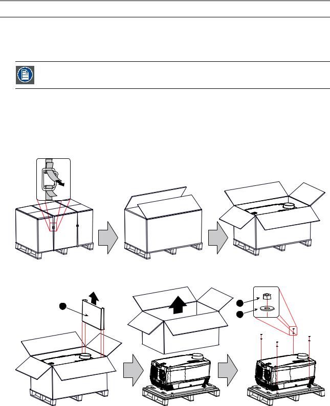
1. Remove the banding around the carton box, by releasing the fastening clips as illustrated, and open the box.
Image 3-1
2. Remove the smaller carton box (reference 1) as illustrated.
Note: The smaller carton box contains the manual.
1
Image 3-2
2
3
3.Remove the carton box and the foam around the projector. See image 3-2.
Note: The projector is still attached to a wooden plate, which is secured the below pallet.
4.Loosen the four nuts (reference 2 image 3-2) which secure the pallet as illustrated. Use a 13 mm open end wrench.
5.Rotate the wooden support plate with projector 90° and slide the front side over the edge of the pallet until the fixation screw (reference 4) is visible as illustrated.
6.Remove the hexagon socket head cap screw (reference 4). Use an 8 mm Allen wrench.
22 |
|
R59770071 DP-2000 06/01/2009 |

3. Mechanical set up of the DP-2000
90°
4
Image 3-3
7.Slide the rear side over the edge of the pallet unit the two fixation screws (reference 5) at the rear are visible.
8.Remove the two hexagon socket head cap screw (reference 5). Use an 8 mm Allen wrench.
5 |
Image 3-4
9.Remove the projector from the wooden support plate and finally remove the 3 extension tubes (reference 6). Use a 17 mm wrench.
6
6 |
Image 3-5
Save the original shipping carton and packing material, they will be necessary if you ever have to ship your projector. For maximum protection, repack your projector as it was originally packed at the factory.
A rubber foam inside a plastic bag is placed into the lens opening of the projector. It’s recommended to reuse this foam and plastic back each time you transport the projector. This to prevent intrusion of dust and foreign particles.
The lens is delivered in a separate box. For lens installation, see section “Lens & lens holder”.
R59770071 DP-2000 06/01/2009 |
|
23 |
3. Mechanical set up of the DP-2000
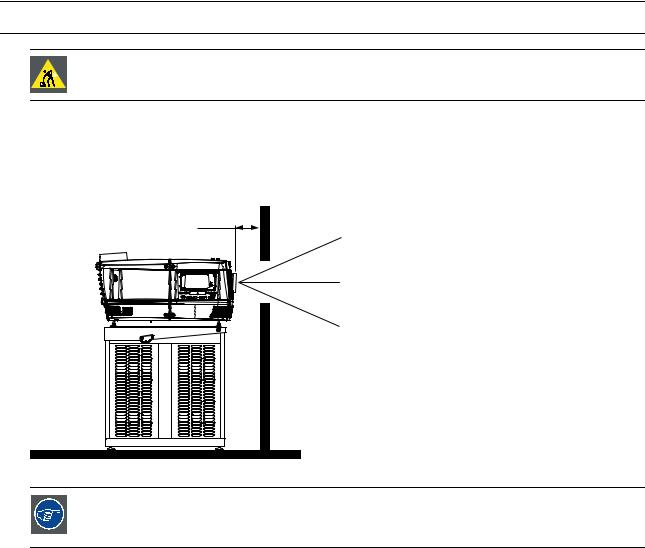
3.2Positioning the DP-2000 at port window
WARNING: The installation of the DP-2000 projector requires at least 2 persons.
General guide lines
•Use a solid pedestal to put the DP-2000 projector on. Ensure that the pedestal can handle the weight of the projector and that all feet of the projector are captured.
•The pedestal should be placed in front of the port window wall in this manner that the projector front cover is at a distance of minimum 20 centimeter from the port window.
20 cm
Image 3-6
Barco offers a pedestal for the DP-1200 digital projector. This universal pedestal allows a solid and easy setup of the projector. The universal pedestal has a separate compartment to install the UPS unit (if available) for the DP-1200 digital projector. Futhermore, the universal pedestal contains a standard 19” rack to build in the projector peripherals like alternative content switchers (e.g. ACS-2048).
Necessary tools
•14 mm wrench.
•17 mm wrench.
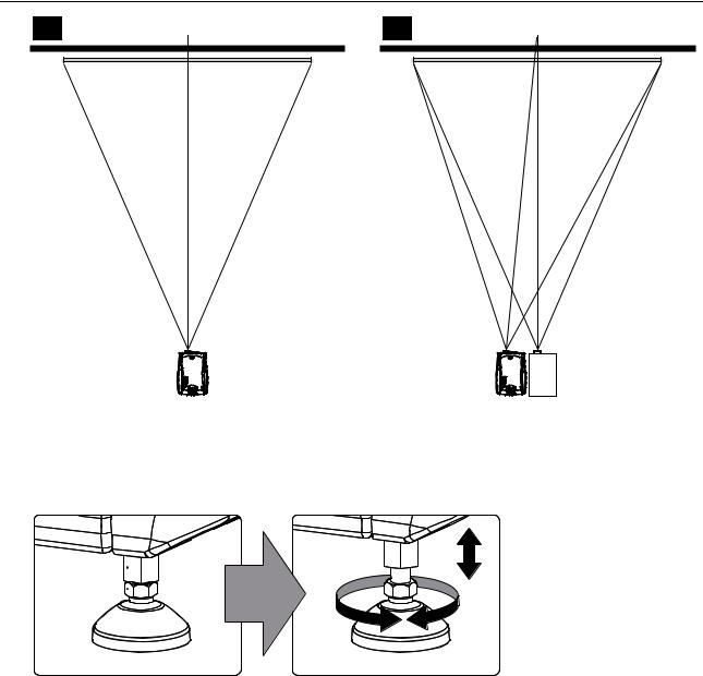
Projector centering
1.If the projector is standalone in front of the port window, center the projector with the theatre screen (see ref A image 3-7).
2.If a film projector is already present (projector will be off-center), try to optimize aim (see ref B image 3-7).
Note: Unlike film projectors, it is best to keep the projector lens surface as parallel to the screen as possible, even if it is significantly above the screen center.
The off-center position slightly increase side keystone, but will minimize horizontal lens offset required.
24 |
|
R59770071 DP-2000 06/01/2009 |
3. Mechanical set up of the DP-2000
A
SCREEN CENTER
B
SCREEN CENTER
CENTER - OFF
Image 3-7
3.Proceed to leveling the projector by adjusting the feet of the projector as follows:
-Loosen the nuts (A), using a wrench of 17 mm, on the threaded rod.
-Adjust the height of the 3 legs (B) to level the projector, using a 14 mm wrench.
-Secure the leg height by tightening the nuts (A).
Note: There must be at least 5 cm between the bottom side of the projector and the pedestal.
A 
B 
Image 3-8
4. Later, when the projector is up-and-running, adjust precise image geometry and placement.
Projector tilting
In an ideal installation, the DP-2000 lens surface is centered with and parallel to the screen. This orientation helps to ensure optimized lens performances with minimal offset. If this position is not possible (such as when the projector is significantly higher than the center of the screen), it is better to rely on offset rather than extra tilt.
1.Before adjusting tilt, make sure the projector is as well-centered with the theatre screen as possible for your installation area.
2.Check with theatre personnel for the degree of screen tilt, or measure this incline with a protractor at the screen.
3.Tilt the projector to closely match this screen tilt angle as follows:
-Loosen the nuts (A), using a wrench of 17 mm, on the threaded rod.
-Adjust the height of the legs until the projected image matches the projection port window and the screen tilt.
-Secure the leg height by tightening the nuts (A).
R59770071 DP-2000 06/01/2009 |
|
25 |

3. Mechanical set up of the DP-2000
90°
Inclined screen
Image 3-9
Barco offers a pedestal for the DP-1200 digital projector. This universal pedestal allows you to easily tilt the projector forward up to 6°.
26 |
|
R59770071 DP-2000 06/01/2009 |
 Loading...