


 Loading...
Barco MDNG-2121, E-3620, MDNC-3121, MDNG-5121, MDNC-2121 User Manual
...Nio
User Guide
Supported displays:
E-3620, MDNG-5121, MDNG-2121, MDNC-3121, MDNG-6121, MDNC-2121
(This page intentionally left blank.)
2 |
Nio |
|
|
||
|
|
|

Welcome!
Nio is Barco's flexible, industry-standard display solution for diagnostic imaging. Presenting an exceptional combination of innovation and performance, Barco's next-generation Nio display system improves your diagnostic reading routine for a multitude of medical imaging applications.
Following symbols may be used throughout this guide:
|
|
Warning: Risk of |
|
Caution: Risk of |
|
|
|
||
|
WARNING |
injury to human |
|
damage to the |
|
|
beings |
|
product |
|
|
|
|
|
|
|
Important notice |
|
Note |
|
|
|
||
|
|
or remark |
|
|
|
|
|
|
|
|
|
Hint, tip |
|
Additional |
|
|
|
||
|
|
|
|
information |
|
|
|
|
|
Read all the safety information starting on page 43 before operating your BARCO NIO Display.
|
Nio |
3 |
|
||
|
|
|
(This page intentionally left blank.)
4 |
Nio |
|
|
||
|
|
|
Table of contents |
|
What's in the box............................................................. |
7 |
Parts, controls and connectors ........................................ |
8 |
Front view ............................................................................................... |
8 |
Rear view ................................................................................................ |
9 |
Display installation ........................................................ |
12 |
Unlocking the height mechanism....................................................... |
12 |
Adjusting the display position ............................................................. |
13 |
Connecting the signal cables............................................................... |
16 |
Routing the cables................................................................................ |
17 |
Re-attaching the covers ....................................................................... |
17 |
VESA-mount installation....................................................................... |
18 |
Daily operation .............................................................. |
20 |
Recommendations for daily operation ............................................... |
20 |
Stand-by switching ............................................................................... |
22 |
Locking and unlocking user controls................................................... |
23 |
Bringing up the OSD menu.................................................................. |
25 |
Navigating through the OSD menus................................................... |
26 |
Making selections in the OSD menus................................................. |
26 |
Changing values in the OSD menus ................................................... |
27 |
Advanced operation ...................................................... |
28 |
On-screen display (OSD) ...................................................................... |
28 |
Input Selection menu*.................................................................. |
28 |
Luminance and color menu ......................................................... |
29 |
Display Function menu* ............................................................... |
30 |
Settings menu ............................................................................... |
33 |
Information menu......................................................................... |
34 |
Changing Display Functions ................................................................. |
35 |
|
Nio |
5 |
|
||
|
|
|
Concepts......................................................................................... |
35 |
Display function selection ............................................................ |
36 |
ALC & DICOM Options.................................................................... |
37 |
Switching DPMS on/off........................................................................ |
40 |
Cleaning your display .................................................... |
41 |
Front glass ............................................................................................. |
41 |
Cabinet................................................................................................... |
42 |
Important information .................................................. |
43 |
Safety information................................................................................ |
43 |
Environmental information.................................................................. |
46 |
Regulatory compliance information.................................................... |
49 |
Explanation of symbols ........................................................................ |
51 |
Legal disclaimer .................................................................................... |
52 |
Technical specifications ........................................................................ |
53 |
6 |
Nio |
|
|
||
|
|
|

What's in the box
Your BARCO NIO Display comes with:
•this BARCO NIO Display guide
•a system CD
•a DVI cable
•a DisplayPort cable (MDNC-2121 only)
•a USB cable
•a set of AC power cords
•an external power supply
If you ordered a Barco display controller, it’s also in the box together with its accessories. A dedicated user guide is available on the system CD.
Keep your original packaging. It is designed for this display and is the ideal protection during transport.
|
Nio |
7 |
|
||
|
|
|

Parts, controls and connectors
Front view
1
2
BARCO
3
Figure 1: Front side
1 Power LED |
2 USB downstream port |
3 Control wheel
8 |
Nio |
|
|
||
|
|
|

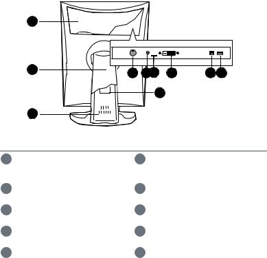
Rear view
REAR VIEW OF E-3620, MDNG-5121
1
|
2 |
4 |
5 |
6 |
7 |
8 |
|
|
|||||
|
|
|
|
9 |
|
|
|
3 |
|
|
|
|
|
|
Figure 2: Rear side |
|
|
|||
1 |
Connector compartment |
|
2 |
Tilt & swivel foot cover |
||
|
cover |
|
|
|
|
|
3 |
Tilt & swivel foot |
|
4 Slot for security cable |
|||
5 |
DVI (digital) video input |
|
6 |
USB upstream port |
||
7 |
USB downstream port |
|
8 |
DC power input |
|
|
9 |
Tilt & swivel foot clip |
|
|
|
|
|
|
Nio |
9 |
|
||
|
|
|
REAR VIEW OF MDNC-3121, MDNG-2121 AND MDNG-6121
1
2 |
3 |
4 |
5 6 |
7 |
8 |
9 |
|
10 |
|
|
|
Figure 3: Rear side
1 |
Connector compartment |
2 |
Tilt & swivel foot cover |
|
cover |
|
|
|
|
|
|
3 |
Tilt & swivel foot |
4 |
DC power input |
|
|
|
|
5 |
+5 Vdc |
6 |
Slot for security cable |
|
|
|
|
7 |
DVI (digital) video input |
8 |
USB upstream port |
|
|
|
|
9 |
USB downstream port |
10 |
Tilt & swivel foot clip |
|
|
|
|
10 |
Nio |
|
|
||
|
|
|
REAR VIEW OF MDNC-2121
1
2 |
3 |
4 |
5 |
6 |
7 |
8 |
9 |
10
Figure 4: Rear side
1 |
Connector compartment |
2 |
Tilt & swivel foot cover |
|
cover |
|
|
|
|
|
|
3 |
Tilt & swivel foot |
4 |
Slot for security cable |
|
|
|
|
5 |
DisplayPort video input |
6 |
DVI (digital) video input |
|
|
|
|
7 |
USB upstream port |
8 |
USB downstream port |
|
|
|
|
9 |
DC power input |
10 |
Tilt & swivel foot clip |
|
|
|
|
|
Nio |
11 |
|
||
|
|
|
Display installation
Prior to installing your BARCO NIO Display and connecting all necessary cables, make sure to have a suitable display controller physically installed in your computer. If you are using a Barco display controller, please consult the dedicated user guide available on the system CD.
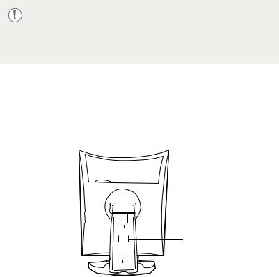
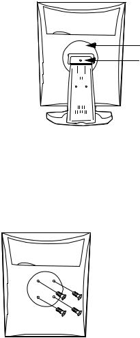
Unlocking the height mechanism
In the factory, the height-positioning system in the display foot is blocked with a red clip to prevent damage during transportation. Before installing the display, you must remove this clip.
Clip
Figure 5: Location of the clip
TO REMOVE THE CLIP:
1 Position the display with its rear side facing you.
2 Pull the red clip out of the fixation holes in the foot.
3 Keep the clip in case the display needs to be shipped later.
12 |
Nio |
|
|
||
|
|
|

Adjusting the display position
You can change the orientation of the panel at any time, but it is more convenient to select landscape or portrait orientation before connecting the cables..
BARCO  BARCO
BARCO
Figure 6: Portrait orientation Figure 7: Landscape orientation
|
Nio |
13 |
|
||
|
|
|
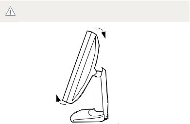
TO CHANGE THE PANEL ORIENTATION
1Stand at the front side of the panel and take the panel at both sides.
2 Very important: Til the panel before changing the orientation.
Should you change the panel orientation without tilting it first, you might irreversibly damage the tilt & swivel mechanism.
Figure 8: Tilt the panel before rotating
14 |
Nio |
|
|
||
|
|
|

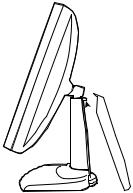
3To change from portrait to landscape, turn the panel counterclockwise.
BARCO
Figure 9: To rotate the panel from portrait to landscape
4 To change from landscape to portrait, turn clockwise..
If, after installing the display or the system, you change the panel orientation while an image is on the screen, the result depends on the graphic board and the resolution of the image. In some cases the image will be rotated automatically, in other cases it will not be rotated (e.g., when pixels would be lost after rotation). If necessary, change the image resolution in the display control panel and restart the system after changing the orientation.
|
Nio |
15 |
|
||
|
|
|

Connecting the signal cables
TO CONNECT THE SIGNAL CABLES TO THE DISPLAY:
To get access to the connectors, remove the connector compartment cover by pulling down the 2 clips at the top of the cover.
The location of the connectors depends on the display type:
1 |
2 |
3 |
4 |
Figure 10: Inputs E-3620, MDNG-5121
4 |
1 |
2 |
3 |
Figure 11: Inputs MDNC-3121, MDNG-2121 and MDNG-6121
1 2
2 3
3 4
4
Figure 12: Inputs MDNC-2121
•Connect one end of the DVI/DisplayPort cable to the DVI/ DisplayPort input of the display (1). Connect the other end of the DVI/DisplayPort cable to the DVI/DisplayPort connector of the display controller board.
•Connect a PC USB downstream connector to the display’s USB upstream connector by means of a USB cable (2).
•Connect any USB device to one of the display’s USB downstream connectors (3)
•Connect the DC power input (4) of the display to the external DC power supply. Connect the other end of the external DC power supply to a grounded power outlet by means of the proper power cord delivered in the packaging.
16 |
Nio |
|
|
||
|
|
|
Routing the cables
•Bind the cables in the connector compartment together with the cable tie inside the connector compartment.
•Put the connector compartment cover back on the display. Pay attention that the signal cables are positioned under the bulge in the cover.
•Push the cables into the clips on the rear of the tilt & swivel foot.
•Bind the cables together above and under the foot, by means of the 2 velcro strips attached to the inside of the foot cover (packed inside the accessory box).
•At last, put the foot cover back in place.
Re-attaching the covers

 (2)
(2)
Figure 13: Installing the cover
1The foot cover is packaged separately in the accessory box. Unpack the foot cover.
2Push the upper side of the cover onto the foot, so that the hooks inside the cover are positioned right under the bulges at the rear of the foot.
|
Nio |
17 |
|
||
|
|
|

3Slide the cover upward while moving the lower side of the cover towards the foot.
4 Press the cover to the foot so that it makes a clicking sound.
VESA-mount installation
The panel, standard attached to the tilt & swivel foot, is compatible with the VESA 100 mm standard. So it can be used with an arm stand according to the VESA 100 mm standard.
Therefore, the tilt & swivel foot must be removed from the panel..
•Use an arm that is approved by VESA (according to the VESA 100 mm standard).
•Use an arm that can support a weight of at least 13 kg (28.66 lbs).
TO ATTACH THE DISPLAY TO AN ARM STAND:
1Put the display face down on a clean and soft surface. Be careful not to damage the panel screen.
2 Remove the tilt & swivel foot cover.
Never move a display attached to an arm by pulling or pushing WARNING the display itself. Instead, make sure that the arm is equipped with a VESA approved handle and use this to move the display.
Please refer to the instruction manual of the arm for more information and instructions.
18 |
Nio |
|
|
||
|
|
|
3Remove the small screw (A) fixing the small plastic cover on top of the foot. Next, remove the small cover itself.
B
A
Figure 14: Display with tilt & swivel foot cover removed
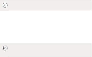
4 Unscrew the 2 screws fixing the round plastic cover (B).
5 Lift up the round plastic cover.
6 Remove the four screws fixing the foot while supporting the foot.
7Attach the arm stand firmly to the panel using 4 screws M4 x 8 mm.
4 screws M4 x 8mm
Figure 15: Location of the screws
|
Nio |
19 |
|
||
|
|
|
Daily operation
Recommendations for daily operation
OPTIMIZE THE LIFETIME OF YOUR DISPLAY
Enabling the Display Power Management System (DPMS) of your display will optimize its diagnostic lifetime by automatically switching off the backlight when the display is not used for a specified period of time. By default, DPMS is enabled on your display, but it also needs to be activated on your workstation. To do this, go to “Power Options Properties” in the “Control Panel”.
Barco recommends setting DPMS activation after 20 minutes of non-usage.
USE A SCREEN SAVER TO AVOID IMAGE RETENTION
Prolonged operation of an LCD with the same content on the same screen area may result in a form of image retention.
You can avoid or significantly reduce the occurrence of this phenomenon by using a screen saver. You can activate a screen saver in the “Display properties” window of your workstation.
Barco recommends setting screen saver activation after 5 minutes of non-usage. A good screen saver displays moving content.
In case you are working with the same image or an application with static image elements for several hours continuously (so that the screen saver is not activated), change the image content regularly to avoid image retention of the static elements.
UNDERSTAND PIXEL TECHNOLOGY
LCD displays use technology based on pixels. As a normal tolerance in the manufacturing of the LCD, a limited number of these pixels may remain either dark or permanently lit, without affecting the diagnostic
20 |
Nio |
|
|
||
|
|
|
performance of the product. To ensure optimal product quality, Barco applies strict selection criteria for its LCD panels.
To learn more about LCD technology and missing pixels, consult the dedicated white papers available at www.barco.com/ healthcare.
ENHANCE USER COMFORT
Every Barco multi-head display system is color matched with the highest specification in the market.
Barco recommends keeping color-matched displays together. Furthermore, it is important to use all displays of a multi-head configuration at the same rate to preserve color matching throughout the economic lifetime of the system.
MAXIMIZE QUALITY ASSURANCE
The ‘MediCal QAWeb’ system offers online service for high-grade Quality Assurance, providing maximum diagnostic confidence and uptime.
Barco recommends to install MediCal QAWeb Agent and apply the default QAWeb policy at least. This policy includes calibration on regular intervals. Connecting to MediCal QAWeb Server offers even more possibilities.
Learn more and sign up for the free MediCal QAWeb Essential level at www.barco.com/healthcare/qa
|
Nio |
21 |
|
||
|
|
|
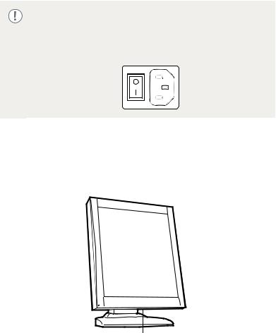
Stand-by switching
The connected power supply also provides a switch that can be used to turn the power completely off. To use the display, please make sure to switch on this power supply. This can be done by pushing the on/off switch on the power supply into the "|" position.
ON E-3620 AND MDNG-5121 DISPLAYS:
When the display is on and no on-screen display is visible, push and hold the control wheel at the front for a few seconds to switch the display in stand-by. The LED turns orange.
BARCO |
Push and hold |
Figure 16: Location of the control wheel
When the display is in stand-by, press the control wheel to switch it back on.
22 |
Nio |
|
|
||
|
|
|
Loading...