


 Loading...
Contents |
|
1. Overview ......................................................................................................... |
5 |
1.1 Introduction ................................................................................................... |
5 |
1.2 Package contents ......................................................................................... |
6 |
1.3 Controls and connectors ............................................................................... |
6 |
2. Installation ....................................................................................................... |
8 |
2.1 Precautions ................................................................................................... |
8 |
2.2 Before installing the display .......................................................................... |
8 |
2.3 Portrait or landscape position ....................................................................... |
9 |
2.4 Connecting the signals ................................................................................. |
9 |
2.5.Routing the signal cables ........................................................................... |
10 |
2.6 Tilt and swivel positioning ........................................................................... |
11 |
2.7 Starting up ................................................................................................... |
11 |
3. Operation ...................................................................................................... |
12 |
3.1. Switching to stand-by position ................................................................... |
12 |
3.2. Controlling the display ............................................................................... |
12 |
3.3. Setting the Luminance value ..................................................................... |
13 |
3.4. Settings ...................................................................................................... |
14 |
3.5. Getting information .................................................................................... |
14 |
4. Advanced functions....................................................................................... |
15 |
4.1. About this chapter ...................................................................................... |
15 |
4.2. Advanced functions in the Luminance menu ............................................. |
16 |
4.3. Advanced functions in the Settings menu.................................................. |
16 |
4.4. Advanced functions in the Information menu............................................. |
17 |
4.5. Advanced functions in the Adjustments menu ........................................... |
19 |
5. Maintenance ................................................................................................. |
20 |
6. Troubleshooting ............................................................................................ |
21 |
7. Technical specifications ................................................................................ |
22 |
User Manual MFGD 3420 |
4 |
1. OVERVIEW
1.1 Introduction
The MFGD 3420, BARCO’s 21” 3 megapixel greyscale LCD display, guarantees perfect image quality in medical imaging applications.
The display combines a TFT (thin film transistor) liquid crystal display panel structure and a built-in backlight with inverter for a better picture quality. It is designed to meet the users' needs for performance, consistency, and outstanding image quality through a streamlined development process.
The display can be used in portrait or landscape version, simply by turning the panel. The tilt & swivel foot allows ideal positioning of the panel, in height and viewing angle.
The image brightness can be adjusted by means of a control wheel on the display. Other image parameters can be adjusted by means of external software, like MediCal® Pro.
I-Guard
I-GUARD® is Barco’s patent-pending, built-in calibration device, continuously maintaining image quality. With I-GUARD®, QA checks no longer need to disturb normal radiology activities, as they can be performed while applications are running.
I-GUARD® allows radiologists or QA administrators to calibrate their viewing stations or adjust the panel’s curve to DICOM standards without administrator intervention.
MediCal Pro
In combination with Barco’s MediCal ® Pro management and calibration software package, Coronis offers a truly intervention-free display system, making it possible to perform QA checks from one central server at any time, thereby reducing lifecycle cost.
Multi-scan capabilities
The optimum and recommended resolution is 2048 x 1536 or 1536 x 2048 at 60 Hz.
The MFGD 3420 display will also display most of the computer boot modes.
BARCO's BarcoMed 3MP2FH imaging board is the best choice to drive the MFGD 3420 display.
User Manual MFGD 3420 |
5 |

1.2 Package contents
The package should include the following items, please check. If some of the items are missing, please contact the reseller you have purchased the unit from.
-The MFGD 3420 display
-12V DC power supply
-European power cord
-American power cord
-Chinese power cord
-Video cable
-This user manual
1.3Controls and connectors
(2)
(3)
(1)
(4) |
(5) |
(6) |
User Manual MFGD 3420 |
6 |
(1)Power LED
-The LED is off when the display is off.
-The LED is green when the display is on.
Note: This function can be switched off by software.
-The LED is blinking green when the display is in Suspend power-saving mode.
-The LED is orange when the display is in Stand-by powersaving mode.
(2)Control wheel for stand-by switching and luminance control
(3)USB-downstream connector
(4)USB-upstream connector
(5)DVI (video and data) input
(6)12V DC power input
User Manual MFGD 3420 |
7 |
2. INSTALLATION
2.1Precautions
•Keep your original packaging. It is designed for this display and is the ideal protection during transport.
•Avoid reflections in the flat panel to reduce eye strain.
•Place the display on a strong and stable table or desk.
•Keep the display away from heat sources and provide enough ventilation in case it is built in a rack or console.
•Make sure the computer is switched off before connecting the signals.
•Do not block or cover the openings in the external power supply block. Also, do not turn the power supply upside down or at its side. Doing so would cause overheating of the power supply.
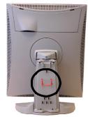
2.2. Before installing the display
Important:
In the factory, the height-positioning system in the display foot is blocked with a strap to prevent damage during transportation.
Before installing the display, you must remove this strap.
To remove the strap:
1 Position the display with its rear side facing you.
2If the foot cover is mounted on the foot, lift up the 2 clips of the foot cover to release the cover from the foot.
3Pull the lower side of the cover towards you and simultaneously slide the cover downward.
4 Pull the red strap out of the fixation holes in the foot.
You can better leave the cover off the foot while connecting the signal cables to the display.
User Manual MFGD 3420 |
8 |
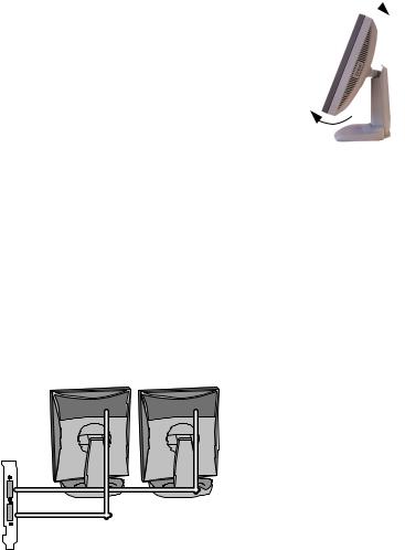
2.3 Portrait or landscape position
You can change the orientation of the panel at any time, but it is more convenient to select landscape or portrait orientation before connecting the cables.
To change the panel orientation:
1 Stand at the front side of the panel and take the panel at both sides. 
2Very important: Tilt the panel before changing the orientation.
Should you change the panel orientation without tilting it first, you might irreversibly damage the tilt & swivel mechanism.
3 To change from portrait to landscape, turn the panel counterclockwise while lifting it up slightly.
To change from landscape to portrait, turn clockwise.
2.4 Connecting the signals
To get access to the connectors, open the cover of the connector compartment by pulling down the 2 clips of the cover.
To connect the video & sync signals:
1Connect one end of the video cable to the DVI input (5) of the display.
2Connect the other end of the video cable to the video output of your video source (Computer graphics board with digital video output).
Vid1 |
Vid2 |
Example of video connection in a Coronis dual head configuration
User Manual MFGD 3420 |
9 |
Loading...