


BARCOPROJECTION
BARCOSLM G8 EXECUTIVE
R9002970
OWNERS MANUAL
01032004 |
R5976450/02 |
Barco nv Events
Noordlaan 5, B-8520 Kuurne Phone: +32 56.36.89.70 Fax: +32 56.36.88.24 E-mail: events@barco.com
Visit us at the web: www.barco.com
Printed in Belgium
Changes
Barco provides this manual ’as is’ without warranty of any kind, either expressed or implied, including but not limited to the implied warranties or merchantability and fitness for a particular purpose. Barco may make improvements and/or changes to the product(s) and/or the program(s) described in this publication at any time without notice.
This publication could contain technical inaccuracies or typographical errors. Changes are periodically made to the information in this publication; these changes are incorporated in new editions of this publication.
Copyright ©
All rights reserved. No part of this document may be copied, reproduced or translated. It shall not otherwise be recorded, transmitted or stored in a retrieval system without the prior written consent of Barco.
Trademarks
Brand and product names mentioned in this manual may be trademarks, registered trademarks or copyrights of their respective holders. All brand and product names mentioned in this manual serve as comments or examples and are not to be understood as advertising for the products or their manufactures.

Table of contents
TABLE OF CONTENTS
1. Safety Instructions .................................................................................................. 5
1.1 Warnings ................................................................................................................................ 5 1.2 FCC statement .......................................................................................................................... 5 1.3 Note ..................................................................................................................................... 5
2. Packaging and Dimensions ....................................................................................... 7
2.1 Box Content ............................................................................................................................. 7
2.2 Projector Packaging .................................................................................................................... 7
2.3 Lens Packaging ......................................................................................................................... 7
2.4 Projector Case .......................................................................................................................... 8
3. Installation Guidelines............................................................................................. 11
3.1 General ................................................................................................................................. 11 3.2 Projector Position ...................................................................................................................... 12 3.3 Configuration ........................................................................................................................... 13 3.4 Safety Area arround the projector ..................................................................................................... 15 3.5 Re-adjusting the lamp position in the lamp casing.................................................................................... 16 3.6 Lenses.................................................................................................................................. 17
3.6.1 Lenses ........................................................................................................................... 18 3.6.2 Lens selection ................................................................................................................... 18 3.6.3 Lens formulas ................................................................................................................... 18 3.6.4 Lens Installation ................................................................................................................. 19 3.6.5 Cleaning the lens ................................................................................................................ 19
3.7 Battery Installation in the RCU ........................................................................................................ 20
4. Connections.........................................................................................................21
4.1 Power connection ...................................................................................................................... 21 4.2 Switching on............................................................................................................................ 21 4.3 Switching to standby ................................................................................................................... 23 4.4 Switching off............................................................................................................................ 23 4.5 Input Source Connections ............................................................................................................. 23
4.5.1 Input Facilities ................................................................................................................... 23 4.5.2 Inputs via RCVDS05 ............................................................................................................ 23 4.5.3 Input module insertion........................................................................................................... 24 4.5.4 Fixed slot (slot 1 & 2)............................................................................................................ 25 4.5.5 Serial Digital Input (slot 3 & 4) .................................................................................................. 26 4.5.6 HD SDI Digital input (slot 3 & 4) ................................................................................................ 27 4.5.7 Digital Video Decoder Input ..................................................................................................... 28
4.6 Communication Connections .......................................................................................................... 30 4.6.1 RS232 (RS422) Connection .................................................................................................... 30 4.6.2 Communication with peripherals................................................................................................ 30 4.6.3 Network connection ............................................................................................................. 30
5. Getting Started......................................................................................................33
5.1 RCU & Local keypad................................................................................................................... 33 5.2 Terminology overview.................................................................................................................. 33 5.3 Operating the projector ................................................................................................................ 35 5.3.1 Switching On .................................................................................................................... 35 5.3.2 Switching to standby ............................................................................................................ 36 5.3.3 Switching off ..................................................................................................................... 36 5.3.4 Temperature error DMD ......................................................................................................... 36 5.4 Quick Set Up Adjustments............................................................................................................. 36 5.4.1 Quick Language Change........................................................................................................ 36 5.4.2 Quick Lens Adjustment.......................................................................................................... 37 5.4.3 Quick On Screen Color change................................................................................................. 38 5.5 Using the RCU ......................................................................................................................... 38 5.6 Projector Address ...................................................................................................................... 40 5.6.1 Controlling the projector......................................................................................................... 40 5.6.2 Displaying and Programming addresses ....................................................................................... 41 5.7 Controlling the Projector ............................................................................................................... 41
6. Start up of the Adjustment mode................................................................................43
6.1 Start up ................................................................................................................................. 43 6.2 Password............................................................................................................................... 43 6.3 Menus on Local LCD Display.......................................................................................................... 44
7. Random Access Adjustment Mode .............................................................................45
7.1 Overview Flow ......................................................................................................................... 45 7.2 Picture Services........................................................................................................................ 46 7.2.1 File annotation................................................................................................................... 46 7.2.2 Possible file manipulations ...................................................................................................... 46 7.2.3 Start up .......................................................................................................................... 47 7.2.4 Load file.......................................................................................................................... 47
R5976450 BARCOSLM G8 EXECUTIVE 01032004 |
|
1 |
|

Table of contents
7.2.5 Edit File .......................................................................................................................... 48 7.2.5.1 Start up.................................................................................................................... 48 7.2.5.2 Changing the settings .................................................................................................... 49 7.2.5.3 Correct value.............................................................................................................. 49 7.2.6 Rename.......................................................................................................................... 52 7.2.7 Copy ............................................................................................................................. 53 7.2.8 Delete ............................................................................................................................ 53 7.2.9 File Options ...................................................................................................................... 54
7.3 Picture Tuning.......................................................................................................................... 55 7.3.1 Start up .......................................................................................................................... 55 7.3.2 CTI ............................................................................................................................... 55 7.3.3 Color Temperature............................................................................................................... 56 7.3.4 Gamma .......................................................................................................................... 56 7.3.5 Decoding......................................................................................................................... 57 7.3.6 Dynamic Color Depth ........................................................................................................... 57 7.3.7 Noise Reduction ................................................................................................................. 58 7.3.8 Input Balance .................................................................................................................... 58
7.3.8.1 Input Balance for RGB input signals ..................................................................................... 59 7.3.8.2 Input Balance for YUV signals ........................................................................................... 60 7.3.8.3 Returning to the factory defaults ......................................................................................... 60 7.4 Geometry............................................................................................................................... 61 7.4.1 Introduction ...................................................................................................................... 61 7.4.2 Geometry start up ............................................................................................................... 61 7.4.3 Shift .............................................................................................................................. 61 7.4.4 Size .............................................................................................................................. 62 7.4.5 Side Keystone ................................................................................................................... 63 7.4.6 Blanking.......................................................................................................................... 64 7.4.7 Aspect Ratio ..................................................................................................................... 65 7.4.8 Geometry Options ............................................................................................................... 66
7.5 ScenergiX .............................................................................................................................. 66 7.5.1 Introduction ...................................................................................................................... 66 7.5.2 Preparations ..................................................................................................................... 67 7.5.3 Scenergix ........................................................................................................................ 68 7.5.4 ScenergiX overlap zone (horizontal scenergix) ................................................................................ 68 7.5.5 ScenergiX overlap zone (vertical scenergix) ................................................................................... 69 7.5.6 ScenergiX size adjustment...................................................................................................... 70 7.5.7 Adjusting the black level of the images ......................................................................................... 72
7.6 Picture in Picture (PiP)................................................................................................................. 73 7.6.1 Introduction to PiP............................................................................................................... 73 7.6.2 Picture in Picture activation ..................................................................................................... 74 7.6.3 Picture in Picture source ........................................................................................................ 74 7.6.4 Position of Picture in Picture window ........................................................................................... 74 7.6.5 Set up of the Quick Selection ................................................................................................... 75
7.7 Save Changes ......................................................................................................................... 75
8. Installation Mode ...................................................................................................77
8.1 Start up of the Installation mode....................................................................................................... 77 8.2 Input Slots .............................................................................................................................. 77 8.3 800 peripheral.......................................................................................................................... 79 8.3.1 Defining the output module of the RCVDS05................................................................................... 79 8.3.2 Defining the Infrared Communication protocol ................................................................................. 79 8.4 Source Switching....................................................................................................................... 80 8.5 No Signal ............................................................................................................................... 80 8.5.1 Changing the Background Color................................................................................................ 81 8.5.2 Changing the Shutdown Setting ................................................................................................ 81 8.5.3 Changing the Shutdown Time .................................................................................................. 81 8.6 Contrast Enhancement ................................................................................................................ 82 8.7 Convergence ........................................................................................................................... 83 8.8 Configuration ........................................................................................................................... 83 8.9 Lens Adjustment ....................................................................................................................... 84 8.10Quick Access Keys .................................................................................................................... 85 8.11OSD .................................................................................................................................... 86 8.11.1Color Settings ................................................................................................................... 86 8.11.2Menu Position ................................................................................................................... 86 8.12Internal Patterns ....................................................................................................................... 86
9. Service Mode........................................................................................................89
9.1 Built-up ................................................................................................................................. 89 9.2 Start up ................................................................................................................................. 89 9.3 Identification............................................................................................................................ 89 9.4 Password............................................................................................................................... 90 9.4.1 Change Password............................................................................................................... 90 9.4.2 Access Control List.............................................................................................................. 91 9.5 Changing Language ................................................................................................................... 93 9.6 Change Projector Address............................................................................................................. 93 9.7 Serial Communication ................................................................................................................. 94
2 |
|
R5976450 BARCOSLM G8 EXECUTIVE 01032004 |
|

Table of contents
9.7.1 Start Up of the Serial Communication .......................................................................................... 94 9.7.2 Baud rate Setting ................................................................................................................ 95 9.7.3 Setting up the Interface Standard............................................................................................... 95 9.7.4 RS422 Termination .............................................................................................................. 96 9.8 Network Configuration ................................................................................................................. 96 9.9 Lamp ................................................................................................................................... 97 9.10Dimming ..............................................................................................................................100 9.11BARCO Logo .........................................................................................................................100 9.12Add-Ins................................................................................................................................101 9.13Preset Input Balance .................................................................................................................101 9.14Advanced Processing ................................................................................................................102 9.14.1Minimum Delay.................................................................................................................102 9.15Diagnosis .............................................................................................................................103 9.15.1How to start up the Diagnosis? ................................................................................................103 9.15.2I2C Diagnoses..................................................................................................................103 9.15.3Formatter .......................................................................................................................104 9.15.4SMPS...........................................................................................................................104 9.15.5LPS (lamp power supply) ......................................................................................................104 9.15.6Voltages ........................................................................................................................105
10.Programmable Function Keys ................................................................................. 107
10.1Function Keys.........................................................................................................................107
A. Standard Source set up Files................................................................................... 109
A.1 Table overview ........................................................................................................................109
B. Barco Control Manager .......................................................................................... 113
B.1 General requirements................................................................................................................. 113 B.2 About the control manager ........................................................................................................... 114 B.3 Control manager Start Page.......................................................................................................... 114 B.4 Control................................................................................................................................. 115 B.4.1 Start up ......................................................................................................................... 116 B.4.2 General Control................................................................................................................. 117 B.4.3 Source .......................................................................................................................... 118 B.4.4 Image Settings.................................................................................................................. 118 B.4.5 Image Enhancement ........................................................................................................... 119 B.4.6 Lens adjustment ................................................................................................................120 B.4.7 Geometry adjustment ..........................................................................................................120 B.4.8 Blanking adjustment............................................................................................................121 B.5 Configuration ..........................................................................................................................122 B.5.1 Start up .........................................................................................................................122 B.5.2 Mail Set up......................................................................................................................123 B.5.3 Security .........................................................................................................................124 B.5.4 Data & Time ....................................................................................................................125 B.5.5 Settings .........................................................................................................................126 B.6 Diagnostics ............................................................................................................................127 B.6.1 Start Up .........................................................................................................................127 B.6.2 General Status..................................................................................................................128 B.6.3 Job Log .........................................................................................................................128 B.6.4 Advanced Diagnostics..........................................................................................................128
Index.................................................................................................................... 131
R5976450 BARCOSLM G8 EXECUTIVE 01032004 |
|
3 |

Table of contents
4 |
|
R5976450 BARCOSLM G8 EXECUTIVE 01032004 |

1. Safety Instructions
1. SAFETY INSTRUCTIONS
1.1 Warnings
To prevent personnel injury
The customer should never attempt to disassemble the lamp casing or to dispose of the lamp casing other than by returning it to BARCO.
To prevent injuries and physical damage, always read this manual and all labels on the system before connecting to the wall outlet, or adjusting the projector.
To prevent injuries, take note of the weight of the projector. Minimum 2 persons are needed to carry the projector.
NEVER look into the lens ! Due to the high luminance damage to the eye can happen.
Before attempting to remove the projector’s cover, you must turn off the projector and disconnect from the wall outlet.
When performing set up work at a ceiling mounted projector, to prevent injury caused by falling objects or the system, set out a keep out area.
Consult a professional structural engineer prior to suspending the ceiling mount from a structure not intended for that use. Always ensure the working load limit of the structure supporting the projector.
The power input at the projector side is considered as the disconnect device. When mentioned to switch of the projector, to access some parts inside, always disconnect the power cord at the projector side.
To prevent projector damage
If the Air Filters are not regularly replaced, the air flow inside the projector could be disrupted, causing overheating. Overheating may lead to the projector shutting down during operation.
In order to ensure that correct airflow is maintained, and that the projector complies with Electromagnetic Compatibility requirements, it should always be operated with all of it’s covers in place.
Ensure that nothing can be spilled on, or dropped inside the projector. If this does happen, switch off and unplug the mains supply immediately. Do not operate the projector again until it has been checked by qualified service personnel.
The projector must always be mounted in a manner which ensures free flow of air into its air inlets and unimpeded evacuation of the hot air exhausted from its cooling system. Heat sensitive materials should not be placed in the path of the exhausted air.
Special care should be used when DLP projectors are used in the same room as performant laser equipment. Direct or indirect hitting of a laser beam on to the lens can severely damage the Digital Mirror Devices (TM) in which case there is a loss of warranty
To prevent battery explosion
Danger of explosion if battery is incorrectly replaced.
Replace only with the same or equivalent type recommended by the manufacturer.
Dispose of used batteries according to the manufacturer’s instructions.
1.2 FCC statement
Federal Communication Commission (FCC Statement)
This equipment has been tested and found to comply with the limits for a class A digital device, pursuant to Part 15 of the FCC rules. These limits are designed to provide reasonable protection against harmful interference when the equipment is operated in a commercial environment. This equipment generates, uses, and can radiate radio frequency energy and, if not installed and used in accordance with the instruction manual, may cause harmful interference to radio communications. Operation of this equipment in a residential area may cause harmful interference, in which case the user will be responsible for correcting any interference.
1.3 Note
Definitions
Definition Qualified service technicians or Qualified technicians : Persons having appropriate technical training and experience necessary to be aware of hazards to which they are exposed in performing a task and of measures to minimize the danger to themselves or other persons.
R5976450 BARCOSLM G8 EXECUTIVE 01032004 |
|
5 |

1. Safety Instructions
Extra Safety manual
Read also safety instructions in separate manual (R5976125).
6 |
|
R5976450 BARCOSLM G8 EXECUTIVE 01032004 |
2. Packaging and Dimensions
2. PACKAGING AND DIMENSIONS
This chapter handles about the way the projector is packed and gives an overview of the dimensions.
•Box Content
•Projector Packaging
•Lens Packaging
•Projector Case
2.1Box Content
Content
•1 projector BARCO SLM G8 (weight ± 46.5 kg or 102.5 lbs)
•1 remote control unit + 2 batteries (1,5V)
•1 European and 1 American power cable
•1 owner’s manual
2.2Projector Packaging
Way of Packaging
The projector is packed in a carton box. To provide protection during transportation, the projector is surrounded with foam. The package is secured with banding and fastening clips.
To unpack
1.Release the fastening clips.
2.Remove the banding. Handle as shown in the drawing. (image 2-1)
3.Take the projector out of its shipping carton and place it on a table.
PULL
TO OPE
Image 2-1
Save the original shipping carton and packing material, they will be necessary if you ever have to ship your projector. For maximum protection, repack your projector as it was originally packed at the factory.
Never transport the projector with the lens mounted on it !
Always remove the lens before transporting the projector.
2.3 Lens Packaging
Way of Packaging
Lenses are supplied as an individual item.
They are packed in a carton.
R5976450 BARCOSLM G8 EXECUTIVE 01032004 |
|
7 |

2. Packaging and Dimensions
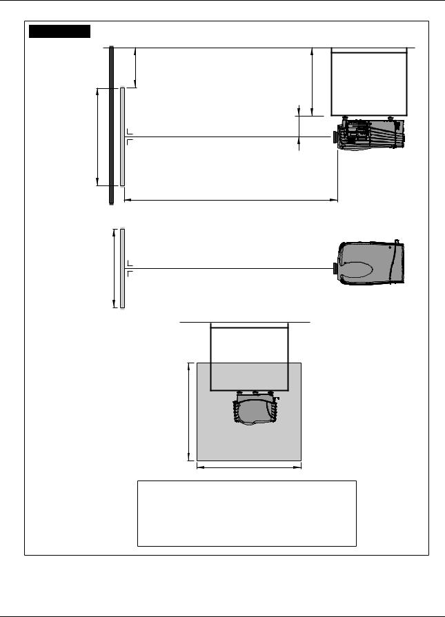
2.4 Projector Case
Dimensions
The dimensions are given in mm and inch (25.4 mm = 1 inch).
IR-reciever
AIR OUT
AIR IN
65.9 mm
(2.59 inch)
(nominal) |
inch) |
407,5 mm (16 04 inch) |
248,3 mm |
(9.77 |
|
190 mm |
190 mm |
(7.48 inch) |
(7.48 inch) |
261,9 mm |
267,1 mm |
(10 31 inch) |
(10 52 inch) |
Image 2-2
Front view dimensions
795,3 mm
(31.31 inch)
372,6 mm (14 67 inch)
IR-receiver
Adjustable feet |
AIR IN |
|
|
544,5 mm |
87,5 mm |
|
(21 44 inch) |
(3 45 inch) |
Image 2-3
Left view dimensions
8 |
|
R5976450 BARCOSLM G8 EXECUTIVE 01032004 |
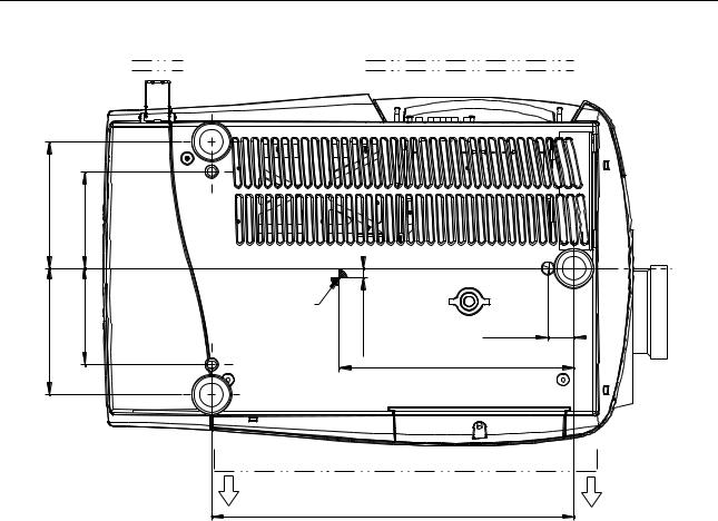
Mains power &
Switch power
190 mm |
(7.48 inch) |
145 mm |
(5.71 inch) |
|
mm190 |
inch)(7.48 |
mm145 |
inch)(5.71 |
Point of gravity |
|
|
|
|
Image 2-4
Bottom view dimensions
2. Packaging and Dimensions
Local keypad,
Display & Inputs
mm |
inch) |
39 mm |
|
14,1 |
(0.56 |
||
(1.54 inch) |
|||
|
|
353,4 mm |
|
|
|
(13.91 inch) |
AIR OUT
544,5 mm
(21.44 inch)
R5976450 BARCOSLM G8 EXECUTIVE 01032004 |
|
9 |

2. Packaging and Dimensions
10 |
|
R5976450 BARCOSLM G8 EXECUTIVE 01032004 |
3. Installation Guidelines
3. INSTALLATION GUIDELINES
Overview
•General
•Projector Position
•Configuration
•Safety Area arround the projector
•Re-adjusting the lamp position in the lamp casing
•Lenses
•Battery Installation in the RCU
The engines are non sealed versions.
3.1 General
Before installing the projector, read first the safety instructions.
Ambient Temperature Conditions.
Careful consideration of things such as image size, ambient light level, projector placement and type of screen to use are critical to the optimum use of the projection system.
Max. ambient temperature : 40°C or 104 °F
Min. ambient temperature : 10 °C or 50 °F
The projector will not operate if ambient air temperature falls outside this range (10°C- 40°C or 50°F-104°F).
Storage temperature: -35°C to +65°C (-31°F to 149°F)
Humidity Conditions
Storage: 0 to 98 % RH Non-condensing
Operation: 0 to 95 % RH Non-condensing
Harmful Environmental Contamination Precaution
Environment
Do not install the projection system in a site near heat sources such as radiators or air ducts, or in a place subject to direct sunlight, excessive dust or humidity. Be aware that room heat rises to the ceiling; check that temperature near the installation site is not excessive.
Environment condition check
A projector must always be mounted in a manner which ensures the free flow of clean air into the projectors ventilation inlets. For installations in environments where the projector is subject to airborne contaminants such as that produced by smoke machines or similar (these deposit a thin layer of greasy residue upon the projectors internal optics and imaging electronic surfaces, degrading performance), then it is highly advisable and desirable to have this contamination removed prior to it reaching the projectors clean air supply. Devices or structures to extract or shield contaminated air well away from the projector are a prerequisite, if this is not a feasible solution then measures to relocate the projector to a clean air environment should be considered.
Only ever use the manufacturer’s recommended cleaning kit which has been specifically designed for cleaning optical parts, never use industrial strength cleaners on the projector’s optics as these will degrade optical coatings and damage sensitive optoelectronics components. Failure to take suitable precautions to protect the projector from the effects of persistent and prolonged air contaminants will culminate in extensive and irreversible ingrained optical damage. At this stage cleaning of the internal optical units will be non-effective and impracticable. Damage of this nature is under no circumstances covered under the manufacturer’s warranty and may deem the warranty null and void. In such a case the client shall be held solely responsible for all costs incurred during any repair. It is the clients responsibility to ensure at all times that the projector is protected from the harmful effects of hostile airborne
R5976450 BARCOSLM G8 EXECUTIVE 01032004 |
|
11 |
|
3. Installation Guidelines
particles in the environment of the projector. The manufacturer reserves the right to refuse repair if a projector has been subject to wantful neglect, abandon or improper use.
Special Care for Laser Beams
Special care should be used when DLP projectors are used in the same room as performant laser equipment. Direct or indirect hitting of a laser beam on to the lens can severely damage the Digital MicroMirror Devices™ in which case there is a loss of warranty
Which screen type ?
There are two major categories of screens used for projection equipment. Those used for front projected images and those for rear projection applications.
Screens are rated by how much light they reflect (or transmit in the case of rear projection systems) given a determined amount of light projected toward them. The ‘GAIN’ of a screen is the term used. Front and rear screens are both rated in terms of gain. The gain of screens range from a white matte screen with a gain of 1 (x1) to a brushed aluminized screen with a gain of 10 (x10) or more. The choice between higher and lower gain screens is largely a matter of personal preference and another consideration called the Viewing angle. In considering the type of screen to choose, determine where the viewers will be located and go for the highest gain screen possible. A high gain screen will provide a brighter picture but reduce the viewing angle. For more information about screens, contact your local screen supplier.
What image size? How big should the image be?
The projector is designed for projecting an image size : min 1.00m (3.3ft) to max 15 m (49.2ft) (depending on the ambient light conditions), with an aspect ratio of 4 to 3.
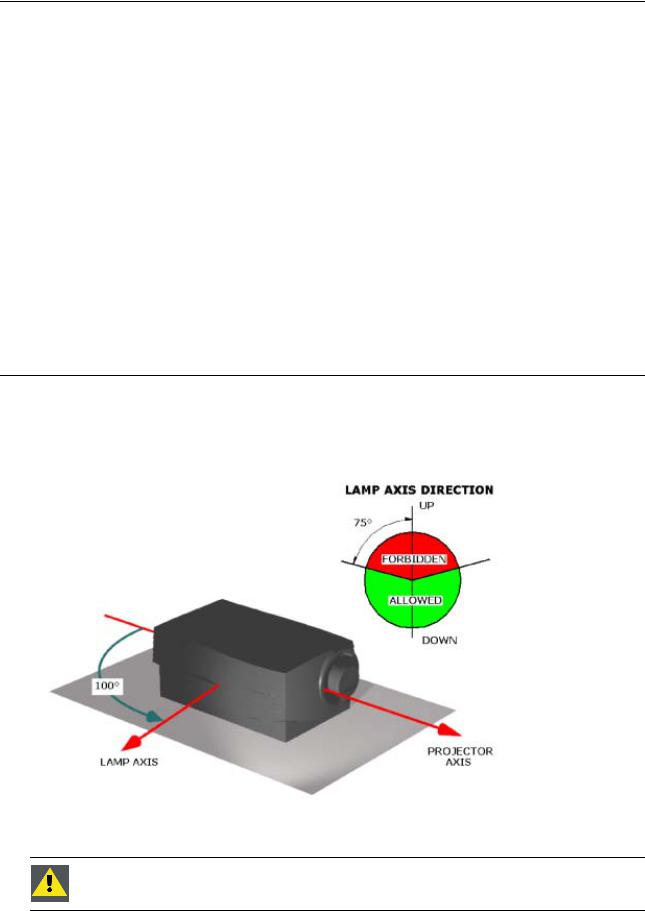
3.2 Projector Position
Projector Position Guidelines
The lamp axis, as it is drawn on this picture, can be oriented according to the specifications:
•pointed in any downward direction
•up to 15° in an upward position.
Image 3-1
Projector position
Never use the projector when turned with the inputs downwards.
12 |
|
R5976450 BARCOSLM G8 EXECUTIVE 01032004 |

3. Installation Guidelines
3.3 Configuration
Which configuration can be used?
The projector can be installed to project images in four different configurations.
•Front Table
•Front Ceiling
•Rear Table
•Rear Ceiling
Positioning the projector
The Projector should be installed perpendicular with the screen on a distance PD and water leveled in both directions. The mounting positions in following images are shown for a nominal lens position.
R5976450 BARCOSLM G8 EXECUTIVE 01032004 |
|
13 |
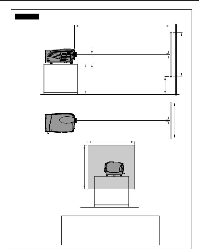
3. Installation Guidelines
Front Table
Side view
PD |
|
Projector |
|
Optical axis projection lens |
SH |
|
|
A |
|
|
Screen |
CD=SH/2+B-A |
|
|
B |
Floor |
|
Optical axis projection lens
Top view |
SW |
Screen
SW
Back view
SH
Floor
Definitions on the abbreviation on the drawings:
A = Correction value.
B = Distance between floor and bottom of the screen.
CD = Total distance between projector and floor.
SW = Screen Width.
SH = Screen Height (Image height).
PD = Projector Distance, distance between screen and projector.
Image 3-2
Front table configuration
14 |
|
R5976450 BARCOSLM G8 EXECUTIVE 01032004 |
3. Installation Guidelines
Front Ceiling
Side view
Bottom view
Ceiling |
|
B |
|
|
CD=SH/2+B-A |
Optical axis projection lens |
A |
|
|
SH |
|
|
Projector |
Screen |
|
PD |
|
|
Projector |
Optical axis projection lens
SW
Screen
Ceiling
Back view
SH
SW
Definitions on the abbreviation on the drawings:
A = Correction value.
B = Distance between ceiling and top of the screen.
CD = Total distance between projector and ceiling.
SW = Screen Width.
SH = Screen Height (Image height).
PD = Projector Distance, distance between screen and projector.
Image 3-3
Front ceiling configuration
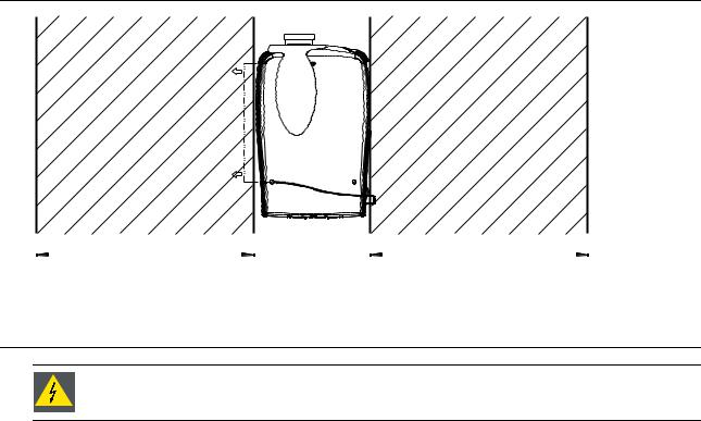
3.4 Safety Area arround the projector
Safety area
Make sure the projector is located so that the air inlets and outlets for the cooling system are not obstructed. Leave a safety area A of about 1 meter on the left and the right side of the projector.
R5976450 BARCOSLM G8 EXECUTIVE 01032004 |
|
15 |
3. Installation Guidelines
AIR OUT
1000 mm |
|
1000 mm |
(39.37 inch) |
|
(39.37 inch) |
Image 3-4
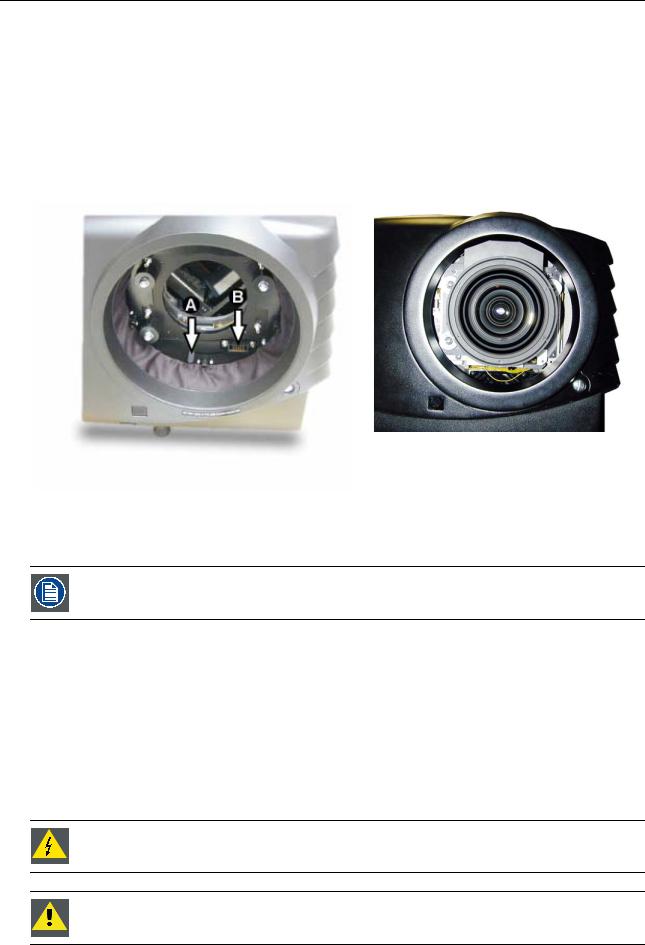
3.5 Re-adjusting the lamp position in the lamp casing
As the projector has to be opened, this procedure has to be performed by qualified service technician.
Why
With higher run times, the light output of the lamp will decrease, which results in a lower light output on the screen. This light output decrease can be compensated by readjusting the position of the lamp.
How to readjust.
1.On the side of the inputs, turn the retaining bolt a quarter counter clockwise.
2.Flip the cover to the left side and take off. (image 3-5)
3.Start up the adjustment mode and select Service. (menu 3-1)
4.Select Lamp. The Z-axis indication (lamp menu in service mode) will be helpful while turning screw B . (menu 3-2)
5.Loosen the nut A (image 3-6)on the back of the lamp casing (nutdriver 10).
6.Adjust the screw B (image 3-6)with an Allen key by turning a little clockwise until the maximum light output is reached (the maximum value of the Z-AXIS indication on the lamp menu).
7.Fasten the nut on the back of the lamp casing to secure this position (nutdriver 10).
ADJUSTMENT MODE |
|
SERVICE |
|
LAMP |
|
|
|
||||
Select a path from below : |
|
IDENTIFICATION |
|
Constant Light output [OFF] |
|||||||
|
|
|
|
CHANGE PASSWORD |
|
Mode [NORMAL] |
|
||||
RANDOM ACCESS |
|
CHANGE LANGUAGE |
|
Serial number : |
R101111 |
||||||
INSTALLATION |
|
CHANGE PROJ. ADDRESS |
|
Article number |
: |
R9840xxx |
|||||
|
SERVICE |
|
|
SERIAL COMMUNICATION |
|
Run time : |
10 hours |
||||
|
|
|
|
NETWORK |
|
Remaining run time : |
490 |
||||
|
|
|
|
|
|
|
|
hours |
|
|
|
|
|
|
|
DIMMING |
|
Number of strikes : |
10 |
||||
|
|
|
|
MORE... |
|
Z_AXIS : 100 |
|
||||
Select with ↑ or ↓ |
|
Select with ↑ or ↓ |
|
Select with ↑ or ↓ |
|
||||||
then <ENTER> |
|
then <ENTER> |
|
|
|||||||
<EXIT> to return |
|
<EXIT> to return |
|
then <ENTER> |
|
||||||
|
|
|
|
|
|
|
|
<EXIT> to return. |
|
||
Menu 3-1 |
|
Menu 3-2 |
|
|
|
|
|
||||
|
|
Menu 3-3 |
|
|
|
||||||
|
|
|
|
|
|
|
|
|
|
|
|
16 |
|
R5976450 BARCOSLM G8 EXECUTIVE 01032004 |
3. Installation Guidelines
Image 3-5
Lamp adjustment access
A
Image 3-6
Never turn the other screws ! These are factory aligned.
3.6 Lenses
Overview
•Lenses
•Lens selection
•Lens formulas
•Lens Installation
•Cleaning the lens
R5976450 BARCOSLM G8 EXECUTIVE 01032004 |
|
17 |

3. Installation Guidelines
3.6.1 |
Lenses |
|
|
Available lenses |
|
|
|
|
|
TLD(1.6–2.0:1) |
R9840670 |
|
|
|
|
TLD(2.0–2.8:1) |
R9840680 |
|
|
|
|
TLD(2.8–5.0:1) |
R9840690 |
|
|
|
|
TLD(1.2:1) |
R9840770 |
|
|
|
|
TLD(0.8:1) |
R9840900 |
|
|
|
|
TLD(5.0–8.0:1) |
R9840910 |
|
|
|
|
TLD HB(0.8:1) |
R9842040 |
|
|
|
|
TLD HB(1.6–2.0:1) |
R9842060 |
|
|
|
|
TLD HB(2.0–2.8:1) |
R9842080 |
|
|
|
|
TLD HB(2.8–5.0:1) |
R9842100 |
|
|
|
|
TLD HB(5.0–8.0:1) |
R9842120 |
|
|
|
3.6.2 |
Lens selection |
|
|
How to select ? |
|
1.Determine the required screen width.
2.Determine the approximate position of the projector in the projection room with regard to the screen and measure the projectorscreen distance (PD).
3.Use the lens formulas to find the best corresponding PD with regard to the measured projector-screen distance for the required screen width.
3.6.3Lens formulas
Formulas
|
Metric formulas (meter) |
Inch formulas (inch) |
|
|
|
TLD(0.8:1) |
PD=0.84xSW-0.05 |
PD=0.84SW-1.97 |
|
|
|
TLD(1.2:1) |
PD=1.20xSW-0.01 |
PD=1.20xSW-0.39 |
|
|
|
TLD(1.6–2.0:1) |
PDmin=1.59xSW-0.09 |
PDmin=1.59xSW-3.54 |
|
PDmax=2.00xSW-0.13 |
PDmax=2.00xSW-5.12 |
|
|
|
TLD(2.0–2.8:1) |
PDmin=2.00xSW-0.17 |
PDmin=2.00xSW-6.69 |
|
PDmax=2.84xSW-0.24 |
PDmax=2.84xSW-9.45 |
|
|
|
TLD(2.8–5.0:1) |
PDmin=2.80xSW-0.16 |
PDmin=2.80xSW-6.30 |
|
PDmax=5.10xSW-0.38 |
PDmax=5.10xSW-14.96 |
|
|
|
TLD(5.0–8.0:1) |
PDmin=4.90xSW-0.01 |
PDmin=4.90xSW-0.39 |
|
PDmax=8.16xSW-0.29 |
PDmax=8.16xSW-11.42 |
|
|
|
Lens program to calculate the projector distance is available on the BARCO web side : http://www.barco.com/projection systems/customer services/lens program.asp
18 |
|
R5976450 BARCOSLM G8 EXECUTIVE 01032004 |
3. Installation Guidelines
3.6.4Lens Installation
How to install ?
Follow the next procedure:
1.Remove the foam rubber in the opening of the lens holder.
2.Take the lens assembly out of its packing material and remove the lens caps on both sides.
3.Move the handle (A) of the lens anchor system to the right. (image 3-7)
4.Push the lens, motors at the top, in the lens block gap horizontally, lining up the motor connector on the lens with the connector on the lens block (B), until the lens clicks in the lens anchor system. (image 3-8)
Caution: On a table mounted projector, hold the projector when pushing the lens into the lens block to avoid sliding off from the table.
Image 3-8
Mounted Lens
Image 3-7
Lens installation
3.6.5Cleaning the lens
To minimize the possibility of damaging the optical coating or scratching exposed lens surface, we have developed recommendations for cleaning the lens. FIRST, we recommend you try to remove any material from the lens by blowing it off with clean, dry deionized air. DO NOT use any liquid to clean the lenses.
Necessary tools
TorayseeTM cloth (delivered together with the lens kit). Order number : R379058.
How to clean the lens ?
Proceed as follow :
1.Always wipe lenses with a CLEAN TorayseeTM cloth.
2.Always wipe lenses in a single direction.
Warning: Do not wipe back and forwards across the lens surface as this tends to grind dirt into the coating.
3.Do not leave cleaning cloth in either an open room or lab coat pocket, as doing so can contaminate the cloth.
4.If smears occur when cleaning lenses, replace the cloth. Smears are the first indication of a dirty cloth.
Do not use fabric softener when washing the cleaning cloth or softener sheets when drying the cloth. Do not use liquid cleaners on the cloth as doing so will contaminate the cloth.
Other lenses can also be cleaned safely with this TorayseeTM cloth.
R5976450 BARCOSLM G8 EXECUTIVE 01032004 |
|
19 |
3. Installation Guidelines
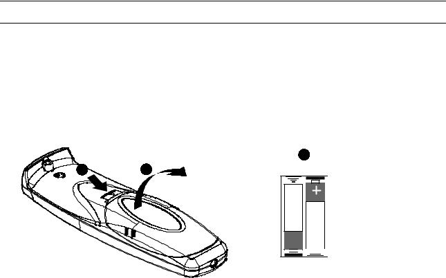
3.7 Battery Installation in the RCU
How are the batteries delivered ?
The batteries (not yet installed to save the battery life time) are delivered inside the plastic bag with the power cord.
How to install
1.Remove the battery cover on the backside of the remote control by pushing the indicated handle a little towards the bottom of the RCU.
2.Lift up the top side of the cover at the same time.
3.Insert the 2 new 1,5 V batteries as indicated in the RCU. (image 3-9)
4.Put the battery cover back on its place.
3
1 |
2 |
RCU Top |
|


 +
+
Image 3-9
Battery installation
20 |
|
R5976450 BARCOSLM G8 EXECUTIVE 01032004 |
4. Connections
4. CONNECTIONS
Overview
•Power connection
•Switching on
•Switching to standby
•Switching off
•Input Source Connections
•Communication Connections
4.1Power connection
AC Power cord connection
Use the supplied power cord to connect your projector to the wall outlet. Plug the female power connector into the male connector at the left of the projector. The power input is 230 VAC.
Fuses
The projector is protected with an automatic circuit breaker of 15A which is built in into the power switch.
4.2 Switching on
How to switch on.
1.Press the power switch to switch on the projector.
-When ’0’ is visible, the projector is switched off.
-When ’1’ is visible, the projector is switched on
The projector starts in standby mode. The projector indication lamp is red.
Starting image projection.
1.Press Stand by key once on the local keypad or on the remote control.
The projector mode indication lamp will be green (image 4-1) Or,
Press a digit button to select an input source.
F2 |
F3 |
F4 |
F1 |
|
F5 |
ADJ  EXIT
EXIT
|
|
|
|
|
1 |
|
|
|
|
|
|
|
|
|
ENTER |
9 |
0 |
STANDBY |
|
EXIT |
|
|
|
7 |
8 |
|
ENTER |
|
|
|
PHASE |
|
|
|
|
|
|||
5 |
6 |
TEXT |
|
PAUSE |
9 |
0 |
SHARPN |
3 |
4 |
SHARPN |
TINT |
BRIGHTN |
7 |
8 |
TINT |
1 |
2 |
PHASE |
COLOR |
CONTRAST |
5 |
6 |
COLOR |
|
|
|
|
|
3 |
4 |
BRIGHTN |
|
|
|
|
|
1 |
2 |
CONTR |
|
|
|
|
|
|
TREBLE |
BALANCE |
|
|
|
|
|
|
BASS |
VOL |
Image 4-1
Standby indication
Lamp run time indication while running
When the total run time of the lamp is 30 hours less then 1000, the following warning message will be displayed for 1 minute. This warning message will be repeated every 30 minutes. Press EXIT to remove the message before the minute is over.
R5976450 BARCOSLM G8 EXECUTIVE 01032004 |
|
21 |

4. Connections
Remaining Lamp run time 20h
Image 4-2
When the total run time of the lamp is 1000 hours or more, the following warning message, with the exact run time is displayed on the screen.
WARNING
Lamp run time is x hours operating the lamp longer than x hours may damage the projector.
Please replace the lamp
<ENTER> to continue
Menu 4-1
Lamp run time is 1000 hours. Operating the lamp longer than 1000 hours may damage the projector. Please replace the lamp.
When ENTER is pressed to go on, the warning will be repeated every 30 min.
The total lifetime of the lamp for a safe operation is 1000 hours max. Do not use it longer. Always replace with a same type of lamp. Call a BARCO authorized service technician for lamp replacement.
Using a lamp for more than 1000 hours is dangerous as the lamp could explode.
Lamp Light Output Indication
When starting up and the center lumens measurement is lower than 50 % of its initial value, the lamp light output warning will be displayed. Press ENTER to continue. The message will not be repeated during operation.
WARNING
Lamp run time is X hours The light output of the lamp is less
than 50% of its initial value. It is advisable to replace the lamp
before damage occurs.
<ENTER> to confirm
Menu 4-2
When the ’Constant Light Output’ (CLO) options is installed, the light output message will appear on the screen when the light output is reduced with 33% from its initial value.
This message will be repeated every hour.
Lamp Z-axis indication
When starting up and the run time is 100 hours or 250 hours a Z-axis warning will be displayed. This warning will advise to adjust the Z-axis of the lamp to obtain maximum light output. Press ENTER to continue. The message will not be repeated during operation.
WARNING
Lamp run time is X hours. It is advisable to adjust the Z-axis
of the lamp to obtain maximum light output
(see owner’s manual)
<ENTER> to confirm
Menu 4-3
22 |
|
R5976450 BARCOSLM G8 EXECUTIVE 01032004 |
4. Connections
4.3 Switching to standby
How to switch to standby?
1.Press Standby to switch the projector to standby.
4.4Switching off
How to switch off the projector?
1.Press first Standby.
2.Let cool down the projector until the fans stop blowing, at least 15 min.
3.Switch off the projector with the power switch.
4.5Input Source Connections
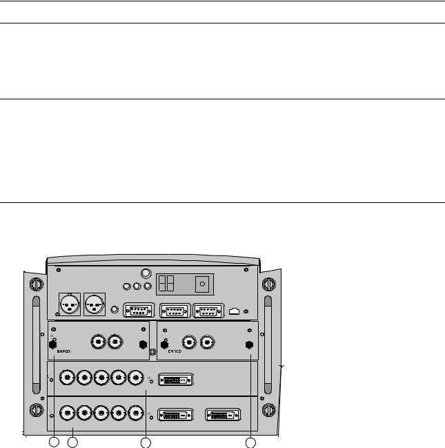
4.5.1 Input Facilities
Overview input facilities
|
|
Green Operation |
Diagnostic Code |
IR-Receiver |
|
|
|
Red Stand-by |
|
|
|
Two way |
Hardwired |
|
|
|
|
hardwired |
|
|
|
|
|
remote |
remote |
|
|
|
|
CTRL 3 |
CTRL 2 |
|
|
|
|
|
|
Sync OK IR |
|
|
|
|
Hardwired |
|
COMM PORT |
10/(100)base-T |
|
|
remote |
RS232/422 IN |
RS232/422 OUT |
||
|
CTRL 1 |
|
|
|
|
OUT |
IN |
9840110 |
IN |
OUT |
On |
|
On |
R9840450 |
|
|
|
|
SDI DIGITAL INPUT |
HD SDI DIGITAL MODULE |
R |
G |
B |
H/C |
V |
|
|
On |
|
|
|
|
On |
|
|
|
|
|
|
|
|
High Bandwidth 5 CABLE INPUT |
DVI INPUT |
|
||||
R |
G |
B |
H/C |
V |
|
|
On |
|
|
|
|
On |
|
|
|
|
|
|
|
|
High Bandwidth 5 CABLE INPUT |
DVI INPUT |
DVI OUTPUT |
||||
3 |
1 |
|
|
2 |
|
4 |
Image 4-3
Input facilities
Input number |
Type of input |
|
|
|
|
1 |
Fixed input, 5 cable input or DVI input and DVI output |
|
|
|
|
2 |
Fixed input, 5 cable input or DVI input |
|
|
|
|
3 & 4 |
Variable inputs |
|
|
Two digital inputs available. |
|
|
• |
SDI input (R9840110) |
|
• |
HD SDI Digital input (R9840450) |
|
Digital Video Decoder (R9841170) |
|
|
|
|
4.5.2Inputs via RCVDS05
Overview
When using a RCVDS05, the input configuration must be as follows:
R5976450 BARCOSLM G8 EXECUTIVE 01032004 |
|
23 |
4. Connections
slot 1 |
RGB/Component |
slot 2 |
Video |
slot 3 |
not used |
slot 4 |
not used |
When using a RCVDS05, it is recommended to use a 5-cable output module in the RCVDS. The outputs of this module has to be connected to slot 1 of the projector. To switch the projector in the 5-cable mode see Fixed slot (slot 1 & 2), page 25.
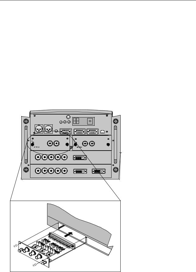
4.5.3Input module insertion
How to insert an input module?
To insert a module in one of the free slots, handle as follow :
1.Power down the projector and disconnect the power cord from the wall outlet.
2.Remove the dummy plate covering the chosen input slot by turning out both screws.
3.Slide the input module in the free slot. Insure the module is seated correctly in the guide grooves.
4.Press on both handles of the input module until the module plug seats in the connector of the projector. (image 4-4)
5.Secure the input module by tightening both retaining screws.
6.Reconnect the power cord to the wall outlet and switch on the projector.
|
|
|
Green Operation |
|
Diagnostic Code |
IR-Receiver |
|
|
|
|
Red Stand-by |
|
|
|
|
Two way |
Hardwired |
|
|
|
|
|
|
hardwired |
|
|
|
|
|
|
|
remote |
remote |
|
|
|
|
|
|
CTRL 3 |
CTRL 2 |
|
|
|
|
|
|
|
|
|
Sync OK |
IR |
|
|
|
|
|
Hardwired |
|
RS232/422 OUT |
COMM PORT |
10/(100)BASE-T |
|
|
|
remote |
RS232/422 IN |
||||
|
|
CTRL 1 |
|
|
|
|
|
|
OUT |
IN |
|
9840110 |
IN |
OUT |
R9840450 |
On |
|
|
|
On |
|
||
|
|
|
|
|
|
||
|
|
SDI DIGITAL INPUT |
HD SDI DIGITAL MODULE |
|
R |
G |
B |
H/C |
V |
High Bandwidth 5 CABLE INPUT |
DVI INPUT |
|
|||
R |
G |
B |
H/C |
V |
|
High Bandwidth 5 CABLE INPUT |
DVI INPUT |
DVI OUTPUT |
|||
Image 4-4 |
24 |
|
R5976450 BARCOSLM G8 EXECUTIVE 01032004 |

4. Connections
How to select the new installed module?
The new installed module can be selected with the digit buttons on the RCU or the local keypad.
4.5.4Fixed slot (slot 1 & 2)
Where to find?
Slot 1 & 2 has 5 BNC input terminals for 5 cable input and a DVI plug for DVI input. Slot 1 has also an DVI output for loop through to a second projector. Within the installation mode it is possible to setup the input for 5 cable or DVI (PanelLink).
Which signals can be connected to slot 1 & 2?
Connector name/ |
R |
G |
B |
H |
V |
Input signal |
|
|
|
|
|
|
|
|
|
|
|
RGBHV |
R |
G |
B |
H |
V |
|
|
|
|
|
|
RGBS |
R |
G |
B |
S |
- |
|
|
|
|
|
|
RGsB |
R |
Gs |
B |
- |
- |
|
|
|
|
|
|
Composite Video |
- |
Video |
- |
- |
- |
|
|
|
|
|
|
Super Video |
- |
Y |
- |
- |
C |
|
|
|
|
|
|
Component Video — SS |
R-Y |
Y |
B-Y |
S |
- |
|
|
|
|
|
|
Component Video — SOY |
R-Y |
Ys |
B-Y |
- |
- |
|
|
|
|
|
|
DVI signals can be connected to the DVI input connector.
Pin assignment for the DVI connector.
Pin 1 |
TMDS DATA2- |
Pin 13 |
TMDS DATA3+ |
Pin 2 |
TMDS DATA2+ |
Pin 14 |
+5 Power |
Pin 3 |
TMDS DATA2/4 Shield |
Pin 15 |
Ground (for +5V) |
Pin 4 |
TMDS DATA4- |
Pin 16 |
Hot Plug Detect |
Pin 5 |
TMDS DATA4+ |
Pin 17 |
TMDS DATA0- |
Pin 6 |
DDC Clock |
Pin 18 |
TMDS DATA0+ |
Pin 7 |
DDC Data |
Pin 19 |
TMDS DATA0/5 Shield |
Pin 8 |
No connect |
Pin 20 |
TMDS DATA5- |
Pin 9 |
TMDS DATA1- |
Pin 21 |
TMDS DATA5+ |
Pin 10 |
TMDS DATA1+ |
Pin 22 |
TMDS Clock Shield |
Pin 11 |
TMDS DATA1/3 Shield |
Pin 23 |
TMDS Clock+ |
Pin 12 |
TMDS DATA3- |
Pin 24 |
TMDS Clock- |
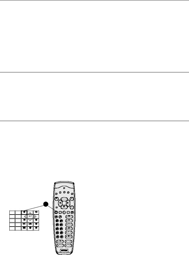
How to select input slot 1 or 2 ?
1. Key in 1 or 2 on the RCU or the local keypad.
How to change the input slot setting?
1.Press ADJUST or ENTER key to start up the Adjustment mode.
2.Push the cursor key ↑ or ↓ to select Installation. (menu 4-4)
3.Press ENTER.
4.Press the cursor key ↑ or ↓ to select Input Slots. (menu 4-5)
R5976450 BARCOSLM G8 EXECUTIVE 01032004 |
|
25 |

4.Connections
5.Press ENTER.
The internal system will scan the inputs and displays the result in the Input Slots menu.
6.Push the cursor key ↑ or ↓ to select the first or second slot. (menu 4-6)
ADJUSTMENT MODE
Select a path from below :
RANDOM ACCESS
INSTALLATION
SERVICE
Select with ↑ or ↓ then <ENTER> <EXIT> to return
Menu 4-4
INSTALLATION |
|
|
INPUT SLOTS |
||
|
|
|
|
|
|
|
INPUT SLOTS |
|
|
|
|
800 PERIPHERAL |
Slot |
Module type [config] |
|||
SOURCE SWITCHING |
1. |
|
RGB-SS [CV] |
||
|
NO SIGNAL |
2. |
|
RGB-SOG |
|
CONTRAST ENHANCEMENT |
3. |
|
SDI |
||
CONVERGENCE |
4. |
|
SDI |
||
CONFIGURATION |
______________ |
||||
|
LENS |
1. |
DVI OUTPUT [DVI input] |
||
QUICK ACCESS KEYS |
|
|
|
||
|
OSD |
|
|
|
|
INTERNAL PATTERNS |
|
|
Select with ↑ or ↓ |
||
Select with ↑ or ↓ |
|
|
|||
|
|
then <ENTER> |
|||
then <ENTER> |
|
|
<EXIT> to return |
||
<EXIT> to return |
|
|
|
||
Menu 4-6
Menu 4-5
Possible indications on the input slot menu.
For the input side:
•RGS-SS [CV or HS&VS] = RGB analog signals, separate sync is composite sync or horizontal and vertical sync.
•RGB-SS [CV] = RGB analog signals, separate sync is composite video.
•RGB-SOG [SOG or 3LSOG] = RGB analog signals, sync on green is composite sync or composite tri-level sync.
•COMPONENT VIDEO - SS [SS or 3LSS] = separate sync is composite sync or composite tri-level sync.
•COMPONENT VIDEO - SOY [SOY or 3LSOY] = component video with composite sync on Y or composite tri-level sync on Y.
•VIDEO
•S-VIDEO
•DVI
When changing from an analog signal on the 5 cable module to the PanelLink input the indication led on the front panel of the module will switch from the 5 cable input to the DVI (PanelLink) input also.
For the output on fixed slot 1:
•DVI input : DVI in signal is looped through to the DVI out connector as it is.
•Active image : active image signal, what ever the input is, is available in DVI on the DVI output signal (processing is incorporated in the signal). Set the minimum delay in Installation > Advanced processing to OFF.
•DVI resync : DVI in signal is resyncronized with a stable clock and put on the DVI out connector
When using an RCVDS 05 with a 5 cable output module, connect these 5 cables to this fixed 5-input slot (slot
1)of the projector. All sources of the RCVDS can now be accepted by the projector.
4.5.5Serial Digital Input (slot 3 & 4)
What can be connected to this input?
This input is full compatibility with digital Betacam, or other digital video sources. This avoids the need for analog video processing anywhere in the video production chain and guarantees the ultimate image quality.
An active loop-through of the SDI input signal is provided for monitoring or for double and or triple stacking applications.
How to connect ?
1.Connect the output of your SDI source to the input BNC of the SDI input. (image 4-5)
Note: The input is always 75 Ω terminated.
2.If loop through is needed, use the OUT to connect to the next device.
26 |
|
R5976450 BARCOSLM G8 EXECUTIVE 01032004 |
 Loading...