


DP2K-6E

DP2K-E series
R5906693/01
19/06/2015
User and installation manual

Barco Visual (Beijing) Electronics Co., Ltd
地址:北京市 昌平区 中关村科技园 昌平园 昌盛路 16号
Phone: +86 10 8010 1166
Fax: +86 10 8970 2793
Support: www.barco.com/en/support
Visit us at the web: www.barco.com
Barco NV
President Kennedypark 35, 8500 Kortrijk, Belgium
Phone: +32 56.36.82.11
Fax: +32 56.36.883.86
Support: www.barco.com/en/support
Visit us at the web: www.barco.com
Printed in Belgium

Changes
Barco provides this manual ’as is’ without warranty of any kind, either expressed or implied, including but not limited to the implied warranties or m erchantability and fitness for a particular purpose. Barco may make improvements and/or changes to the product(s) and/or the
program(s) described in this publication at any time without notice.
This publication could c ontain technical inaccuracies or typographical errors. Changes are periodically made to the information in this
publication; these changes are incorporated in new editions of this publication.
The latest edition of Barco manuals can be downloaded from the Barco web site w
h
ttps://www.barco.com/en/signin.
ww.barco.com or from the secured Barco web site
Copyright ©
All rights reserved. No part of this document may be copied, reproduced or translated. It shall not otherwise be recorded, transmitted or
stored in a retrieval system without the prior written consent of Barco.
Federal Communications Commis sion (FCC Statement)
This equipment has been tested and found to comply with the limits for a class A digital device, pursuant to Part 15 of the FCC rules.
These limits are designed to provide reasonable protection aga inst harmful interference when the equipment is operated in a commercial
environment. This equipment generates, uses, and can radiate radio frequency energy and, if not installed and used in accordance with
the instruction m anual, may cause harmful interference to radio communications. Operation of this equipment in a residential area may
cause harmful interference, in which case the user will be responsible for correcting any interference at his own expense
Changes or modifications not expressly approved by the party responsible for compliance could void the user’s authority to operate the
equipment
EN55022/CISPR22 Class A ITE (Information Technology Equipment)
Class A ITE is a category of all other ITE which satisfies the class A IT
be restricted in its sale but the following warning shall be included in the instructions for use:
Warning : This is a class A product. In a dom estic environment this product may cause radio interference in which case the user may be
required to take adequate measures.
E limits but not the class B ITE limits. Such equipment should not
Guarantee and Compensation
Barco provides a guarantee relating to perfect manufacturing as part of the legally stipulated terms of guarantee. On receipt, the purchaser
must immediately inspect all delivered goods for damage inc urred during transport, as well as for material and manufacturing faults Barco
must be informed immediately in writing of any complaints.
The period of guarantee begins on the date of transfer of risks, in the case of special systems and software on the date of commissioning,
at latest 30 days after the transfer of risks. In the event of justified notice of complaint, Barco can repair the fault or provide a replacement
at its own discretion within an appropriate period. If this measure proves to be impossible o r unsuccessful, the purchaser can demand a
reduction in the purchase price or cancellation of the contract. All other claims, in particular those relating to compensation for direct or
indirect damage, and also damage attributed to the operation of software as well as to other services provided by Barco, b eing a component
of the system or independent service, will be deemed invalid provided the dam age is not proven to be attributed to the absence of properties
guaranteed in writing or due to the intent or gross negligence or part of Barco.
If the purchaser or a third party carries ou
in particular if the systems are o perated incorrectly or if, after the transfer o f risks, the goods are subjec t to influences not agreed upon in
the contract, all guarantee claims of the purchaser will be rendered invalid. Not included in the guarantee co verage are system failures
which are attributed to programs or spe
maintenance are n ot subject to the guarantee provided by Barco either.
The environmental conditions as well as the servicing and m aintenance regulations specified in this manual m ust be complied with by the
customer.
t modifications or repairs on goods delivered by Barco, or if the goods ar e handled incorrectly,
cial electronic circuitry provided by the purchaser, e.g. interfaces. Normal wear as well as normal
Software License Agreement
You should carefully read the following terms and conditions before u sing this software. Your use of this software indicates your acceptance
of this license agreement and warranty.
Terms and Conditions:
1. No redistribution of the software is allowed.
2. Reverse-Engineering. You m ay not reverse engineer, decompile, disassemble or alter this software product.
Disclaimer of Warranty:
This software and the accompanying files are sold “as is” and without warranties as to performance or merchantability or any other warranties whether expressed or im plied. In no event shall Barco be liable for damage of any kind, loss of data, loss of profits, business

interruption or o ther pecuniary loss arising directly or indirectly. Any liability of the seller will be exclusively limited to replacement of the
product or refund of purchase price.
GNU-GPL code
If you would like a copy of the GPL source code contained in this product shipped to you on C D, p lease contact Barco. T he cos t of preparing
and mailing a CD will be charged.
Trademarks
Brand and product names mentioned in this manual may be t rademarks, registered trademarks or copyrights of their respective holders.
All brand and product names mentioned in this manual serve as commen ts or examples and are not to be understood as advertising for
the products or their m anufacturers.

Table of contents
TABLE OF CONTENTS
1. Welcome ......... ................ ................ ................ .................. ................ ................ .. 3
1.1 About this manual . . .................................................................................................................. 4
2. Safety................................................................................................................. 5
2.1 General considerations ............................................................................................................... 6
2.2 Important safety instructions ......................................................................................................... 7
2.3 Product safety labels ................................................................................................................10
2.4 Light beam Hazard Distance (HD) .................................................................................................. 11
2.5 HD in function of the lens Throw Ratio (TR)........................................................................................ 13
3. Getting started ................ ................ ................ ................ ................ ................ .....15
3.1 Installation requirements .. . .........................................................................................................16
3.2 Unpacking the projector .............................................................................................................18
3.3 Initial inspection......................................................................................................................20
4. Installation process ...............................................................................................21
4.1 Installation process overview........................................................................................................ 22
5. Physical installation ..............................................................................................23
5.1 Positioning the DP2K-E series projector at port window ...........................................................................24
5.2 Connecting the projector with the power net .......................................................................................27
5.3 Connecting a UPS to the projector electronics . . ................................................................................... 28
6. Lenses & Lens selection .........................................................................................31
6.1 Available lenses ..................................................................................................................... 32
6.2 Lens selec tion .......................................................................................................................33
6.3 Lens installation .....................................................................................................................34
6.4 Lens removal ........................................................................................................................35
6.5 Lens shift, zoom & focus . . .......................................................................................................... 36
7. Input & Communication..........................................................................................39
7.1 Introduction ..........................................................................................................................40
7.2 Local Keypad ........................................................................................................................41
7.3 ProjectorStatus......................................................................................................................43
7.4 Cinema Controller ................................................................................................................... 45
8. ICMP ........ ................ ................ ................ .................. ................ ................ .......47
8.1 ICMP introduction. . . .................................................................................................................48
8.2 ICMP HDD ........................................................................................................................... 50
8.3 ICMP communication ports ......................................................................................................... 51
8.4 ICMP s ource input ports............................................................................................................. 53
8.5 ICMP reset button and status LEDs ................................................................................................58
8.6 ICMP HDD status LEDs ............................................................................................................. 59
8.7 ICMP device certificate..............................................................................................................61
8.8 ICMP configuration via Communicator .............................................................................................63
8.9 Obtaining the Barco ICMP certificate ...............................................................................................64
8.10 Removing a HDD form the ICMP ...................................................................................................65
8.11 Installing a HDD into the ICMP......................................................................................................66
9. Communicator Touch Panel.............. .................. ................ ................ ................ .....69
9.1 Communicator Touch Panel.........................................................................................................70
9.2 Installing the Touch Panel interface.................................................................................................72
9.3 Repositioning the Touch Panel interface . . . ........................................................................................ 74
10. Starting up... .................. ................ ................ ................ ................ ................ .....75
10.1 Switching the DP2K-E series projector ON.........................................................................................76
10.2 Switching the DP2K-E series projector OFF........................................................................................77
11. Scheimpflug........................................................................................................79
11.1 Scheimpflug introduction .. . .........................................................................................................80
11.2 Scheimpflug adjustment.............................................................................................................82
11.3 Fixation of the Lens Holder front plate ..............................................................................................84
11.4 Back Fo cal Length adjustment ......................................................................................................86
12. Convergence ............ ................ ................ ................ ................ .................. .........91
12.1 Convergence controls ............................................................................................................... 92
12.2 Preparing for convergence adjustme nt . . . . .........................................................................................94
12.3 Converging the bluepattern onto the red pattern ..................................................................................96
12.4 Converging the green pattern onto the redpattern................................................................................. 97
12.5 Closing off the Light Processor compartment . .....................................................................................98
13. Lamp House. ................ ................ ................ ................ ................ .................. .....99
13.1 Introduction .........................................................................................................................100
13.2 Removal of the Lamp Module ......................................................................................................101
R5906693 DP2K-E SERIES 19/06/2015
1

Table of contents
13.3 Installation of the Lamp House .....................................................................................................103
13.4 Resetting the lamp parameters . . . .................................................................................................105
14. Preventative maintenance actions ...... ................ ................ ................ ................ ..... 107
14.1 1 month maintenance actions......................................................................................................108
14.2 3 month maintenance actions......................................................................................................109
15. Maintenance procedures................ ................ ................ ................ ................ ........111
15.1 Check the dust fi lters...............................................................................................................112
15.2 Vacuum cleaning of the dus t filters ................................................................................................113
15.3 Washing and drying the dust filters ................................................................................................114
15.4 Cleaning the lens . . . ................................................................................................................115
15.5 Cleaning the exterior of the projector ..............................................................................................116
15.6 Authorization to clear security warning on the projector ..........................................................................117
16. Removal and installation of the projector covers .. ................ ................ ................ ....... 119
16.1 Removal of the front cover .........................................................................................................120
16.2 Removal of the rear cover..........................................................................................................121
16.3 Removal of the top cover...........................................................................................................122
16.4 Removal of the left sidecover......................................................................................................123
16.5 Removal of the right side cover ....................................................................................................125
16.6 Removal of the top cover plate ofthe Light Processor compartment.............................................................126
16.7 Removal of the side cover plate of the Light Processor compartment ...........................................................127
16.8 Installation of the side cover plate of the Light P rocessor compartment .........................................................128
16.9 Installation of the top cover plate of the Light Process or compartment...........................................................129
16.10 Installation of the right side cover..................................................................................................130
16.11 Installationof the left side cover ...................................................................................................131
16.12 Installation of the top cover.........................................................................................................133
16.13 Installation of the rear cover........................................................................................................134
16.14 Installation of the front cover.......................................................................................................135
17. Specifications.................................................................................................... 137
17.1 Specifications of the DP2K-6E .....................................................................................................138
17.2 Specifications of the ICMP .........................................................................................................140
17.3 Dimensions of the DP2K-Eseries projector.......................................................................................142
17.4 Dimensions of the universal pedestal..............................................................................................143
17.5 Technical Regulations ..............................................................................................................144
18. Pin configurations.......... ................ ................ ................ ................ ................ ..... 145
18.1 About G eneral Purpose Inputs & Outputs (GPIO).................................................................................146
18.2 Pin configurations of the Cinema Controller communication ports ...............................................................148
18.3 Pin configurations of the ICMP communication ports .............................................................................149
19. Environmental information.................................................................................... 153
19.1 Disposal information................................................................................................................154
19.2 RoHS compliance ..................................................................................................................155
19.3 Hazards.............................................................................................................................157
19.4 Production address . ................................................................................................................158
19.5 Importers contact information ......................................................................................................159
2
R5906693 DP2K-E SERIES 19/06/2015

1. Welcome
1. WELCOME
Congratulations
May we congratulate you on your purchase of a Barco DP2K -E series projector! It is our sincere wish that this digital projector meets
up to your every expectation and that you thereby take a little time to page through this important manual. Familiarizing yourself
with it’s features, important safety ins tructions and necessary maintenance a ctions, will ensure you enjoy m any years of reliable,
trouble-free high quality performance.
Overview
• About this manual
R5906693 DP2K-E SERIES 19/06/2015
3

1. Welcome
1.1 About this manual
How to use this manual?
We suggest that you read over this manual before you install and use your DP2K-E se ries projector. Inside it, you will find important
information regarding safety, installation and maintenance. We urge even the experienced user to take the necess ary time to page
through this manual. We believe everyone will benefi t from this manual. Not in the least our editors, who will sleep more comfortably
knowing their efforts have had their effect.
What’s expected from you?
For your safety and in th e interest of reliable, trouble-free, high quality performance, we urge the user/operator/service technician,
to follow all instructions precisely. Follow the maintenance recommendations and procedures in this manual step by step to keep
your projector in excellent condition. Doing so will directly impact the lifetime of your DP2K-E series projector.
If, after having read over these instructions, you ex perience difficulties, please contact your
best to assist you and get you up and running as soon as possible.
“Treat your DP2K-E series projector as your own and it will reward you with many trouble-free years of exquisite digital
entertainment pleasure!”
Barco service partner! They will do their
4
R5906693 DP2K-E SERIES 19/06/2015

2. SAFETY
About this chapter
Read this chapter attentively. It contains important information to prevent personal injury while ins talling and using your DP2K-E series projector. F urthermore, it includes several cautions to prevent damage to your DP2K-E series projector. Ensure that you
understand and follow all safety guidelines, safety instructions and warnings mentioned in this chapter before installing and using
the DP2K-E series projector. A fter this chapter, additional “warnings” and “cautions” are given depending on the procedure. Read
and follow these “warnings” and “cautions” as well.
Clarification of the term “DP2K-E series” used in this document
When r eferring in this document to the term “DP2K-E series” means that the content is applicable for following Barco products:
•DP2K-6E
Barco provides a guarantee relating to perfect manufacturing as part of the legally stipulated terms of guarantee. Observing the specification mentioned in this chapter is critical for projector performance. Neglecting
this can result in loss of warranty.
Overview
• General considerations
• Important safety instructions
• Product safety labels
• Light beam Hazard Distance (HD)
• HD in function of the lens Throw Ratio (TR)
2. Safety
R5906693 DP2K-E SERIES 19/06/2015
5

2. Safety
2.1 General considerations
General safety instructions
• Before operating this equipment please read this manu al thoroughly and retain it for future reference.
• Installation and preliminary adjustments should be performed by qualified Barco personnel or by authorized Barco service dealers.
• All warnings on the projector and in the doc umentation manuals should be adhered to.
• All instructions for operating and use of this equipment must be followed precisely.
• All local installation codes should be adhered to.
Notice on electrical safety
This equipment is built in accordance with the requirements o f the international safety standards IEC60950-1, EN60950-1,
UL60950-1 and CAN/CSA C22.2 No.60950-1, which are the safety standards of information technology equipment including
electrical business equipment. These safety standards impose important requirements on the us e of safet
materials and insulation, in order to protect the user or operator against risk of electric shock and energy hazard and having access
to live parts. Safety standards also impose limits to the internal and external temperature rises, radiation levels, mechanical stability
and strength, enclosure construction and protection against the risk of fire. Simulated single fau
safety of the equipment to the user even when the equipment’s normal operation fails.
lt condition testing ensures the
Users definition
Throughout this manual, the terms SERVICE PERSONNEL and TRAINED PROJE CTIONIST refers to persons having appropriate
technical training and experience necessary to be knowledgeable of potential hazards to which they are exposed (including, but not
limited to HIGH VOLTAGE ELECTRIC and ELECTRONIC CIRCUITRY and HIGH BRIGHTNESS PROJECTORS) in performing a
task, and of measures to minimize the potential risk to thems elves or other persons. The term USER and OPERATOR refers to
any person other than SERVICE PERSON NEL or TRAIN ED PROJECTIONISTS, AUTHORIZED to operate professional projection
systems.
The TRAINED PROJECTIONISTS may only perform the maintenance task described in the U ser & Installation manual. All other
maintenance tasks and service tasks must be performed by qualified SERVICE PERSONNEL.
The DLP Cinem a Systems are intended "FOR PROFESSIONAL USE ONLY" by AUTHORIZED PERSONNEL familiar with potential
hazards associated with high voltage, high intensity light beams, ultraviolet exposure and high temperatures generated by the lamp
and associated circuits. Only qualified SERVICE PERSONNEL and TRAINED PROJECT IONISTS, know ledgeable of such risks,
are allowed to perform service functions inside the product enclosure.
y critical components,
Owner’s record
The part number and serial number are printed on a label whic
provided below. R efer to them whenever you call upon your Barco dealer regarding this produc t.
Product article number
Product serial number
Dealer
h is stuck on the respective part. Record these num bers in the spaces
6 R5906693 DP2K-E SERIES 19/06/2015

2.2 Important safety instructions
To prevent the risk of electrical shock
• This projector should be operated from an AC power source. E nsure that the mains voltage and capacity matches the projector
electrical ratings. If you are unable to install the AC requirements, contact your electrician. Do not defeat the purpose of the
grounding.
• Installation according to the local electrical c ode and regulations by qualified technical personnel only.
• A readily accessible disconnect device must be incorporated externally to the equipment for removal of the power to the pr ojector cord.
• Warning: High leakage current. Earth connection essential before connecting supply.
• Do not allow anything to rest on the power cord. Do not locate this projector where persons will walk on the cord.
• Do not op erate the projector with a damaged cord or if the projector has been dropped or damaged - until it has been examined
and approved for operation by a qualified service te chnician.
• Position the cord so that it will not be tripped over, pulled, or contact hot surfaces.
• If an extension cord is necessary, a cord with a current rating at least equal to that of the projector should be used . A cord rated
for less amperage than the projector may overheat.
• Never push objects of any kind into this projector through cabinet slots as they may touch dangerous voltage points or short
circuit parts that could result in a risk of fire or electrical shock.
• Do not expose this projector to rain or moisture.
• Do not immerse or expose this projector in w ater or other liquids.
• Do not spill liquid of any kind on this projector.
• Should any liquid or solid object fall into the cabinet, unplug the set and have it checked by qualified service personnel before
resuming operations.
• Do not disassemble this projector, always take it to a trained service person when service or repair work is required.
• Do not use an accessory attachm ent which is not recommended by the m anufacturer.
• Lightning - For added protection for this video product during a lightning storm, or when it is left unattended and unused for
long periods of time, remove all power from the projector. This will prevent damage to the projector due to lightning and AC
power-line surges.
2. Safety
R5906693 DP2K-E SERIES 19/06/2015
7

2. Safety
To prevent personal injury
• Isolate electrically before replacing the lamp or lamp house. Caution: Hot lamp (house).
• Caution: High pressure lam p may explode if improperly handled. Refer servicing to qualified service personnel.
• To prevent injury and physical damage, always read this manual and all labels on the s ystem before inserting the lamp casing,
powering the projector or adjusting the projector.
• To prevent injury, take note of the weight of the projector. Minimum 4 adult persons are needed to carry the projector.
• To prevent injury, ensure that the lens and all cover plates are c orrectly installed. See installation procedures.
• Warning: high intensity light beam. NEVER look into the lens ! High luminance could result in damage to the eye.
• Warning: extremely high brightness lamps: This projector uses extremely high brightness lamps. Never attempt to look
directly into the lens or at the lamp. If the pr ojection distance is less than 6 meter, any person needs to be at least 4 meters
away from the projected image. Avoid close range reflection of the projected image on a ny reflecting surface (such as glass,
metal, …) . When operating the projector, we strongly recommend wearing suitable safety g lasses.
• Before attempting to remove any of the projector’s covers, disconnect the projector power cord for removal of all power from
the projector.
• When required to remove all power from the projector, to access parts inside, always disconnect the projector power cord for
removal of all power from the projector.
• Do not place this equipment on an unstable cart, stand, or table. The product may fall, causing serious damage to i
possible injury to the user.
• It is hazardous to operate without lens or shield. Lenses, shields or ultra violet screens shall be changed if they have become
visibly damaged to such an extent that their effectiveness is im paired. For example by cracks or deep scratches.
• Warning: Protection from ultraviolet radiation: Do not look directly in the light beam. T he lamp contained in this p roduct is
an intense source of light and heat. One component of the light emitted from this lamp is ultraviolet light. Potential eye and skin
hazards are present when the lamp is energized due to ultraviolet radiation. Avoid unnecessary exposure. Protect yourself and
your employees by ma king them aware of the hazards and how to protect themselves. Protecting the skin c an be accomplished
by wearing tightly woven garments and gloves. Protecting the eyes from UV c an be accomplished by wearing safety glasses
that are designed to provide UV protection. In addition to the UV, the visible light from the lamp is intense and should also be
considered when choosing protective eye wear.
• Mercury Vapor Warnings: Keep the following warnings in mind when using the projector. The lamp used in t he projector
contains mercury. In case of a lamp rupture, explosion there will be a mercury vapor emission. In order to minimize the potential
risk of inhaling mercury vapors:
- Ensure the projector is installed only in ventilated rooms.
- Replace the lamp module before th e end of its operational life.
- Promptly ventilate the room after a lamp rupture, explosion has occurred, evacuate the room (particularly in case of a pre g-
nant woman).
- Seek medical attention if unusual health conditions occur after a lamp rupture, explosion, such as headache, fatigue, short-
ness of breath, chest-tightening coughing or nausea.
• Exposure to UV radiation: Some medications are known to make individuals ex tra sensitive to UV radiation. The American
Conference of Governmental Industrial Hygienists (ACGIH)
less than 0,1 micro-watts per square centimeters of effective UV radiation. An evaluation of the workplace is advised to assure
employees are not exposed to cumulative radiation levels exceeding these government guidelines.
recommends occupational UV exposure for an-8 hour day to be
t and
To prevent fire hazard
• Do not place flamma ble or combustible materials near the projector!
• Barco large screen projection products are des igned and manufactured to meet the most stringent safety regulations. This
projector radiates heat on its external surfaces and from ventilation ducts during normal operation, which is both normal and
safe. Exposing flammable or co mbus tible materials into close proximity of this projector could result in the spontaneous ignition
of that material, resulting in a fire. For this reason, it is absolutely necessary to leave an “exclusion zone” around all external
surfaces of the projector whereby no flammable or combustible materials are present. The exclusion zone must be not less
than 40 c m (16”) for all DLP Cinem a projectors. The exclusion zone on the lens side must be at least 5 m. Do not cover the
projector or the lens with any material while the projector is in operation. Keep flam mab le and combustible materials away from
the projector at all times. Mount the projector in a well ventilated area away from sources of ignition and out of direct s un light.
Never expose the projector to rain or moisture. In the event of fi re, use sa nd, CO
water on an electrical fi re. Always have service performed on this projector by authorized B arco service personnel. Always
insist on genuine Barco replacement parts. Never use non -Barco replacement parts as they may degrade the safety of this
projector.
• Slots and openings in this equipment are provided for ventilation. To ensure reliable operation of the projector and to protect
it from overheating, these opening
projector too close to walls, or other similar surface. This projector s hould never be placed near or over a radiator or heat
register. This projector should not be placed in a built-in installation or enclosure unless proper ventilation is provided.
• Projection rooms m ust be well ventilated or cooled in order to avoid build up of heat. It is necessary to vent hot exhaust air from
console to the outside of the building.
• Let the projector cool completely before storing. Remove cord from the projector when storing.
• Heat sensitive materials should not be placed in the path of the exhaust a ir or on the lamp house.
8
s must not be blocked or covered. The openings should never be blocked by placing the
or dry powder fi re extinguishers. Never use
2
R5906693 DP2K-E SERIES 19/06/2015

2. Safety
To prevent projector damage
• This projector has been designed for use with a specific lamp (house) type. See installation instructions for its correct type.
•Theairfilters of the projector must be cleaned or replaced on a regular basis (a "clean" booth would be m onthly-minimum).
Neglecting this could result in disrupting the air flow inside the projec tor, causing overheating. Overheating may lead to the
projector shutting down during operation.
• The projector must always b e installed in a manner which ensures free flow of air into its air inlets.
• In order to ensure that correct airflow is maintained, and that the projector complies with Electromagnetic Compatibility (EMC)
and safety requirements, it should always be operated with all of it’s covers in place.
• Slots and openings in the cabinet are provided for ventilation. To ensure r eliable operation of the product and to protect it from
overheating, these openings mus t not be blocked or covered. The openings should never be blocked by placing the p roduct
on a bed, sofa, rug, or other similar surface. This product should never be placed near or over a radiator or heat register. The
device should not be plac ed in a built-in installation or enclosure unless pro per ventilation is provided.
• Ensure that nothing can be spilled on, or dropped inside the projector. If this does ha ppen, switch off and remove all power
from the projector. Do not operate the projector again until it has been checked by qualified service pe
• Do not block the projector cooling fans or free air movem ent around the projector. Loose papers or other objects may not be
nearer to the projector than 10 cm (4") on an y side.
• Do not use this equipment near water.
• Proper operation of the projector can only be guaranteed in table mounting. It is not permitted to use the projector in another
position. See installation procedure for correct installation. A ceiling mount will be supported in the future.
• Special care for Laser Beams: Special care should be used when DLP projectors are used in the same room as hi
laser equipment. Direct or indirect hitting of a laser beam on to the lens can severely damage the Digital Mirror Devices
which case there is a loss of warranty.
• Never place the projector in direct sunlight. Sunlight on the lens can severely damage the Digital Mirror Devices
case there is a loss of warranty.
• Save the original shipping carton and packing material. They will come in handy if you ever have to ship your equipment. For
maximum protection, repack your set as it was originally packed at the factory.
• Disconnect the power to the projector before cleaning. Do not use liquid cleaners or aerosol cleaners. Use a damp cloth for
cleaning. Nev er use strong so lvents, such as thinner or benzine, or, patrol, or abrasive cleaners, since these will damage the
cabinet. Stubborn stains may be removed with a cloth lightly dampened with mild detergent solution.
• To ensure the highest optical performance and resolution, the projection lenses are specially treated with an anti-reflective
coating, therefore, avoid touching the lens. To remove dust on the lens, use a soft dry cloth. Do not use a damp cloth, detergent
solution, or thinner.
• Rated maximum ambient temperature, t
• The lamp hou se shall be replaced if it has become damaged or thermally deform ed.
• Do not stack DP2K-E series projectors.
= 35°C (95°F).
a
rsonnel.
gh power
TM
in which
TM
in
On servicing
• Do not attempt to service this product yourself, as opening or removing covers may expose you to dangerous voltage potentials
and risk of electric shock.
• Refer all s ervicing to qualified service personnel.
• Attempts to alter the factory-set internal controls or to change other control settings not specially dis cussed in this manual can
lead to permanent damage to the projector and cancellation of the warranty.
• Remove all power from the projector and refer servicing to qualified service technicians under the following conditions:
- When the power cord or plug is damaged or frayed.
- If liquid has been spilled into the equipment.
- If the product has been exposed to rain or water.
- If the product does not operate normally wh en the operating instructions are followed. Adjust only those controls that are
covered by the operating instructions since improper adjustmen
require extensive work by a qualified technician to restore the product to normal operation.
- If the product has been dropped or the cabinet has been damaged.
- If the product exhibits a distinct change in performance, indicating a need for service.
• Replacement parts: When replacement parts ar e required, be sure the service technician has used original Barco replacement
parts or authorized replacement parts whic h have the same cha racteristics as the B arco original part. Unauthorized substitutions m ay result in degraded performance and reliability, fire, electric shock or other hazards. Unauthorized substitutions may
void warranty.
• Safety check: Upon completion of any service or repairs to this projector, ask the service technician to perform safety checks
to determine that the product is in proper operating c
• Possible explosion hazard: Always keep in mind the caution below:
ondition.
t of the other controls may result in damage and will often
To prevent battery explosion
• Danger of explosion if battery is incorrectly installed.
• Replace only with the same or equivalent type recommended by the manufacturer.
• For disposal of used batteries, always consult federal, state, local and provincial hazardous waste disposal rules and regulations
to ensure proper disposal.
R5906693 DP2K-E SERIES 19/06/2015
9
2. Safety
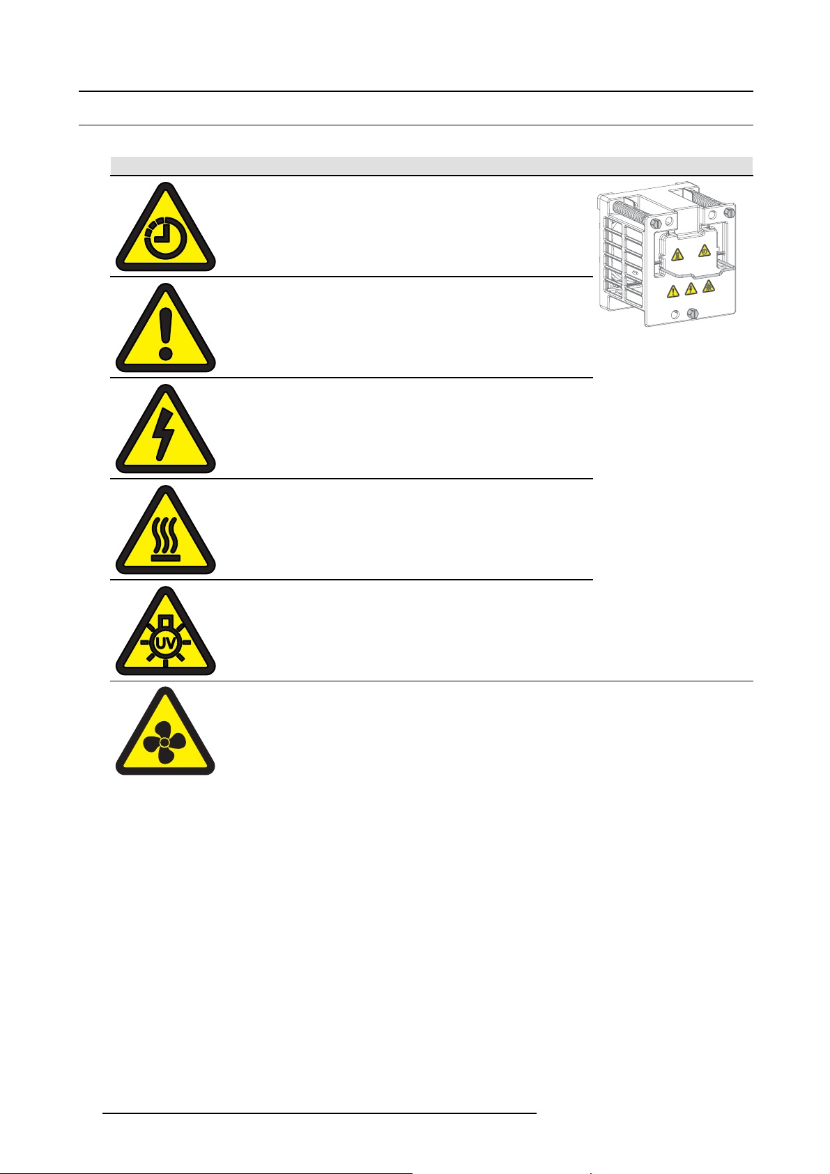
2.3 Product safety labels
Product safety labels
Label image Label description Label location
The Lamp House is very hot after operation. To avoid
burns, let the projector cool down for at least 15 minutes
before proceeding to remove the Lamp House.
General Warning Hazard
Electric Voltage Hazard
Hot Surface Hazard
UV Hazard
Hazardous moving parts.
Keep away from moving fan blades.
Keep fingers and other body par ts away.
On the fans inside the projector
10 R5906693 DP2K-E SERIES 19/06/2015
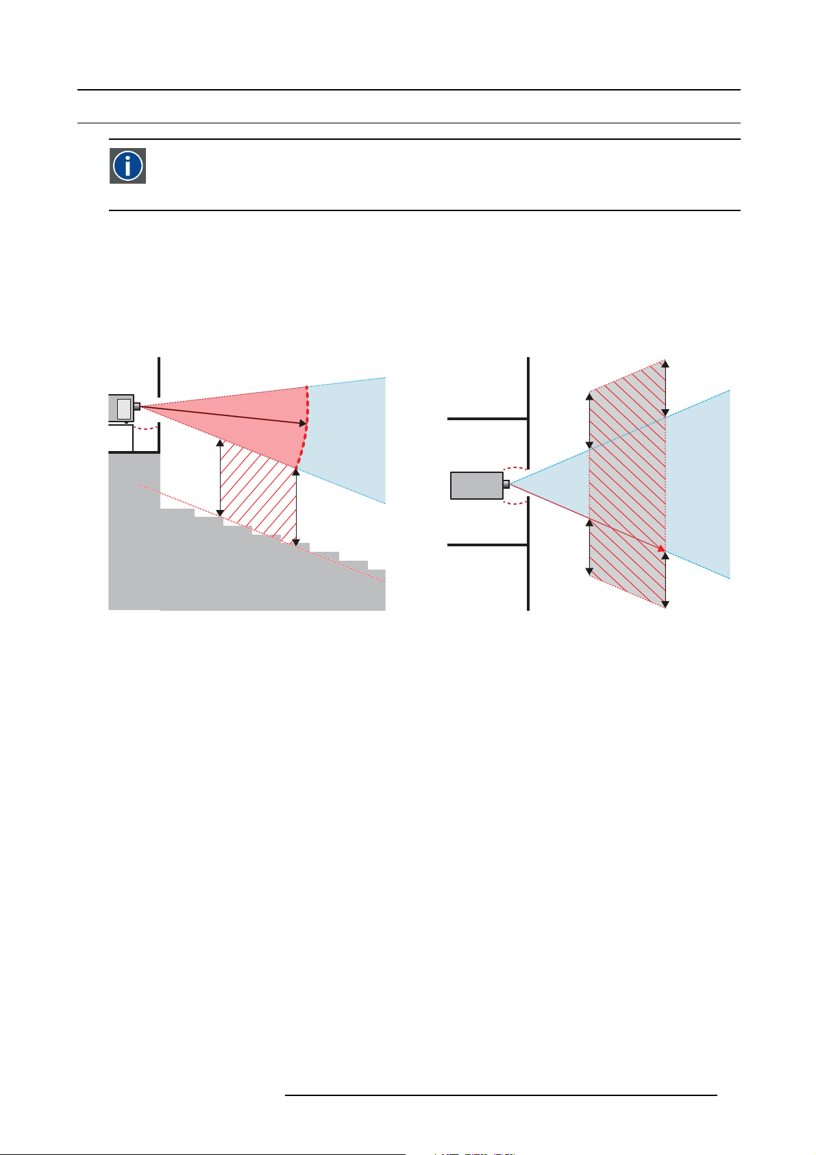
2.4 Light beam Hazard Distance (HD)
HD
Light beam Hazard Distance (HD) is the distance from the source at which the intensity or the energy per sur face unit
becomes lower than the applicable safety limit. The light beam can thus be considered as dangerous if the operator
is closer from the source than the HD.
Restriction Zone (RZ) based on the HD
The HD is defined from the projection lens surface towards the position of the lowest projected beam where the irradiance equals
the applicable safety limit. T he HD depends on the amount of lumens produced by the projector and the type of lens installed. See
next chapter HD in function of the lens Throw Ratio (TR).
To protect untrained users the installation shall comply with the following installation requirements: light output levels in excess of the
limits shall not be permitted at any point less than 2.0 meters (SH image 2-1) above any surface upon which persons are assumed
to stand or 1 meter (SW image 2-1) below or in lateral separation from any place where such persons are as sum ed to be. See
image 2-1.
2. Safety
RA TH
HD
RA
SH
RZ
SH
Image 2-1
ASideview.
B Top view.
RA Restricted Access location (booth area of projector).
PR P rojector.
TH Theater.
RZ Restriction Zone in the theater.
SH S eparation Height. Must be minimum 2 meter.
SW Separation W idth. Must be minimum 1 meter.
Based on national requirements, no person is allowed to enter the projected beam within the zone between the projection lens and
the related hazard distance (HD). This s hall be physically impossible by creating sufficient separation height or by placing bar riers.
The minimum separation height takes into account the surface upon which persons are assumed to stand.
On image 2-1 a typical setup is displayed. It must be ve rified by the installer if these m inimum requirements are m et. If r equired a
restricted zone (RZ) in the theater must be established. This can be done by using physical barrier, like a red rope as illustrated in
image 2-2.
PR
(B) TOP VIEW(A) SIDE VIEW
TH
HD
SW
SW
SW
RZ
1m
SW
R5906693 DP2K-E SERIES 19/06/2015
11
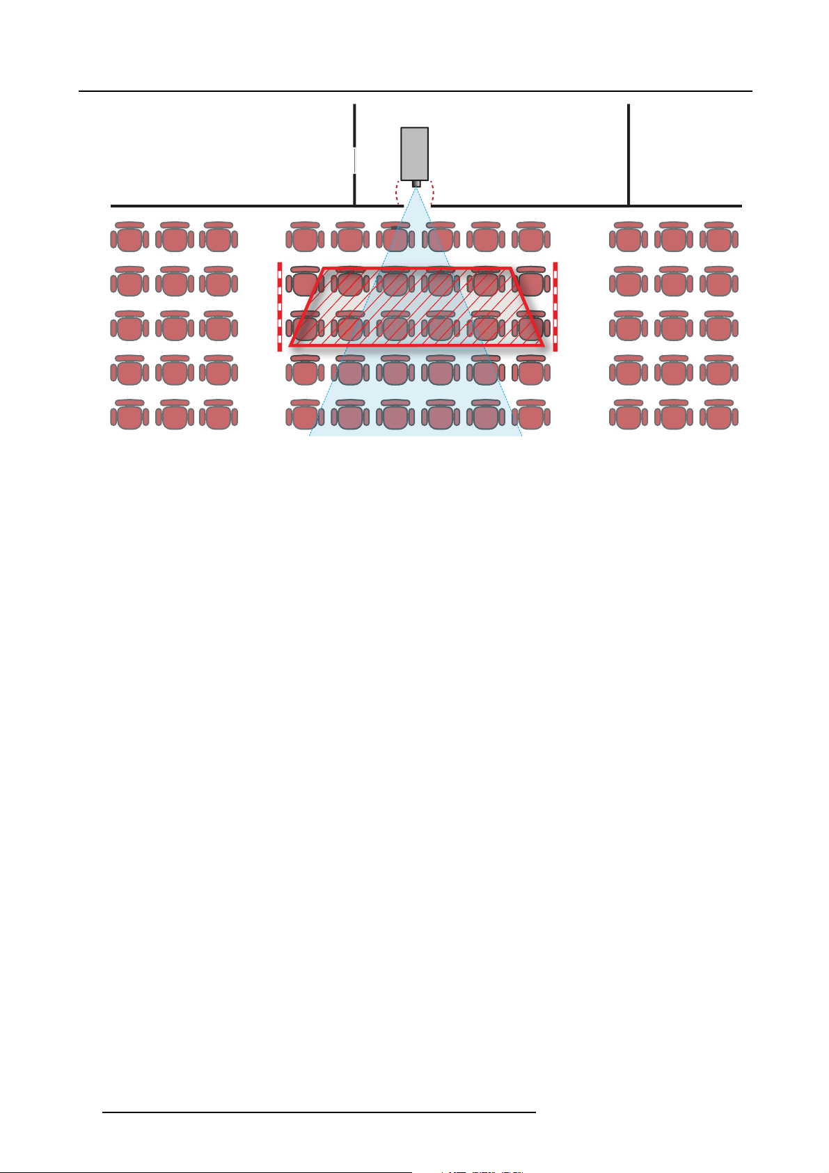
2. Safety
Image 2-2
PR
12 R5906693 DP2K-E SERIES 19/06/2015
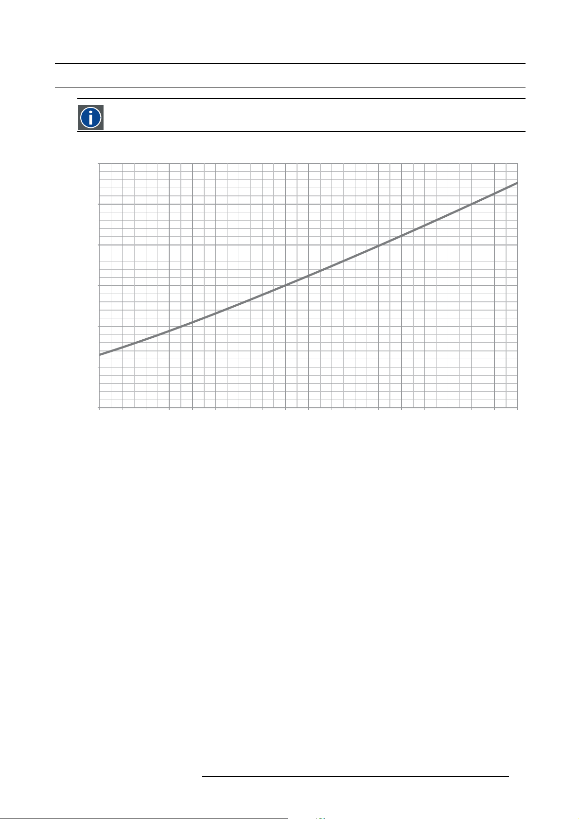
2.5 HD in function of the lens Throw Ratio (TR)
TR (Throw Ratio)
The ratio of the distance to the screen (throw) to the screen width.
Hazard Distance
1,2
1
0,8
0,6
HD [m]
0,4
2. Safety
0,2
0
1,0 1,2 1,4 1,6 1,8 2,0 2,2 2,4 2,6 2,8 3,0 3,2 3,4 3,6 3,8 4,0 4,2 4,4 4,6
Image 2-3
HD (in meter) in function of the Throw Ratio (TR)
TR
R5906693 DP2K-E SERIES 19/06/2015 13

2. Safety
14 R5906693 DP2K-E SERIES 19/06/2015

3. Getting started
3. GETTING STARTED
About this chapter
Read this ch apter before installing your DP2K-E series projector. It contains important information conc erning installation requirements for the DP2K-E series projector, such as minimum and maximum allowed am bient temperature, humidity conditions, required
safety area around the installed projector, required power net, etc.
Furthermore, careful consideration of things such as image size, ambient light level, projector placement and type of screen to use
are critical to the optimum use of the projection system.
Barco provides a guarantee relating to perfect manufacturing as part of the legally stipulated terms of guarantee. Observing the specification mentioned in this chapter is critical for projector performance. Neglecting
this can result in loss of warranty.
Overview
• Installation requirements
• Unpacking the projector
• Initial inspection
R5906693 DP2K-E SERIES 19/06/2015
15

3. Getting started
3.1 Installation requirements
Environment conditions
Table below summarizes the physical environment in wh ich the DP2K-E series projector may be safely operated or stored.
Environment Operating Non-Operating
Ambient Temperature 10°C (50°F) to 35°C (95°F) -20°C (-4°F) to 60°C (140°F)
Air cleanliness Clean office environment (equivalent with cleanroom
Humidity
Altitude
Let t he projector acclimatize after unpacking. Neglecting this may result in a startup failure of the Light Processor Unit.
standard ISO 14644-1 ISO Class 9)
0% to 85% RH Non-condensed 0% to 93% RH Non-Condensed
-60 (-197Ft) to 2000m (9843Ft) -60 (-197Ft) to 10000m (32810Ft)
Cooling requirements
The projector is fan cooled and must be installed with sufficient space around the projector head, minimum 20 cm (8 inch) to ensure
sufficient air flow. It s hould be used in an area where the ambient temperature, as measured at the projector air inlet, does not
exceed 35°C (95°F).
Main Power requirements
The DP2K-E series projector operates from a nominal mono phase power net with a separate earth ground PE.
n.a.
Projector Power requirements
DP2K-6E
The powe r cord required to connect the projector with the power net is not delivered with the projector. It is the responsibility of the
customer to provide the correct type of power cord. The cross-sectional area of the conductors in the power supply cord shall not
be less than 1mm
To protect operating personnel, the National Electrical Manufacturers Association (NEMA) recommends that the instrument panel
and cabinet be grounded. In no event shall this projector be operated without an adequate ca binet ground c onnection.
The AC supply must be installed by a qua lified electrician in conformance to local codes. Hardware, wire sizes and conduit types
must comply with local codes.
A re adily accessible disconnect device shall be inco
2
(18AWG), minimu m 300V.
200-240 VAC, 50-60Hz, 6,25A at 200 VAC
rporated externally to the equipment for removal of the power.
UPS requirements
The Uninterruptible Power Supply (UPS), also known as a Continuous Power Supply (CPS), must have an output voltage of 20 0240V at 50-60Hz and must be capable of delivering an output power of 250W. This UPS provides only power for the electronics and
lamp cooling, but not for the lamp .
The connection between the UPS unit and the UPS inlet of the projector must be done with a certified AC power supply cord of
minimum 0,75 mm² or 18 AWG and minimum 300V.
WARNING: Disconnect the power cord for removal o f all power f rom the unit.
The DP2K-E series projector does not have a built in UPS unit.
Projector weight
Do not unde restimate the weight of the DP2K-E series projector. The projector weights approximately 53 kg (116.8 lb.) without lens.
Ensure that the pedes tal on which the projector is installed is capable of supporting the complete load of the system. Minimum 4
adult persons are needed to carry the projector.
16
R5906693 DP2K-E SERIES 19/06/2015

3. Getting started
Barco offers a pedestal for the DP2K-E series projector. This universal pedestal allows for a solid and easy
setup of the projector. The universal pedestal support 19” rack systems. (pro jector peripherals such as alternative content switchers, ShowVault, etc.)
R5906693 DP2K-E SERIES 19/06/2015 17
3. Getting started
3.2 Unpacking the projector
What you need to do?
Upon delivery, your projector is packed into a carton box upon a wooden/plastic pallet and sec ured with banding and fastening clips.
Furthermore, to provide protection during transportation, the projector is surrounded by foam. Once the projector has arrived at
the installation site, it needs to be removed from its carton box and wooden/plastic pallet in a safe manner without damaging the
projector.
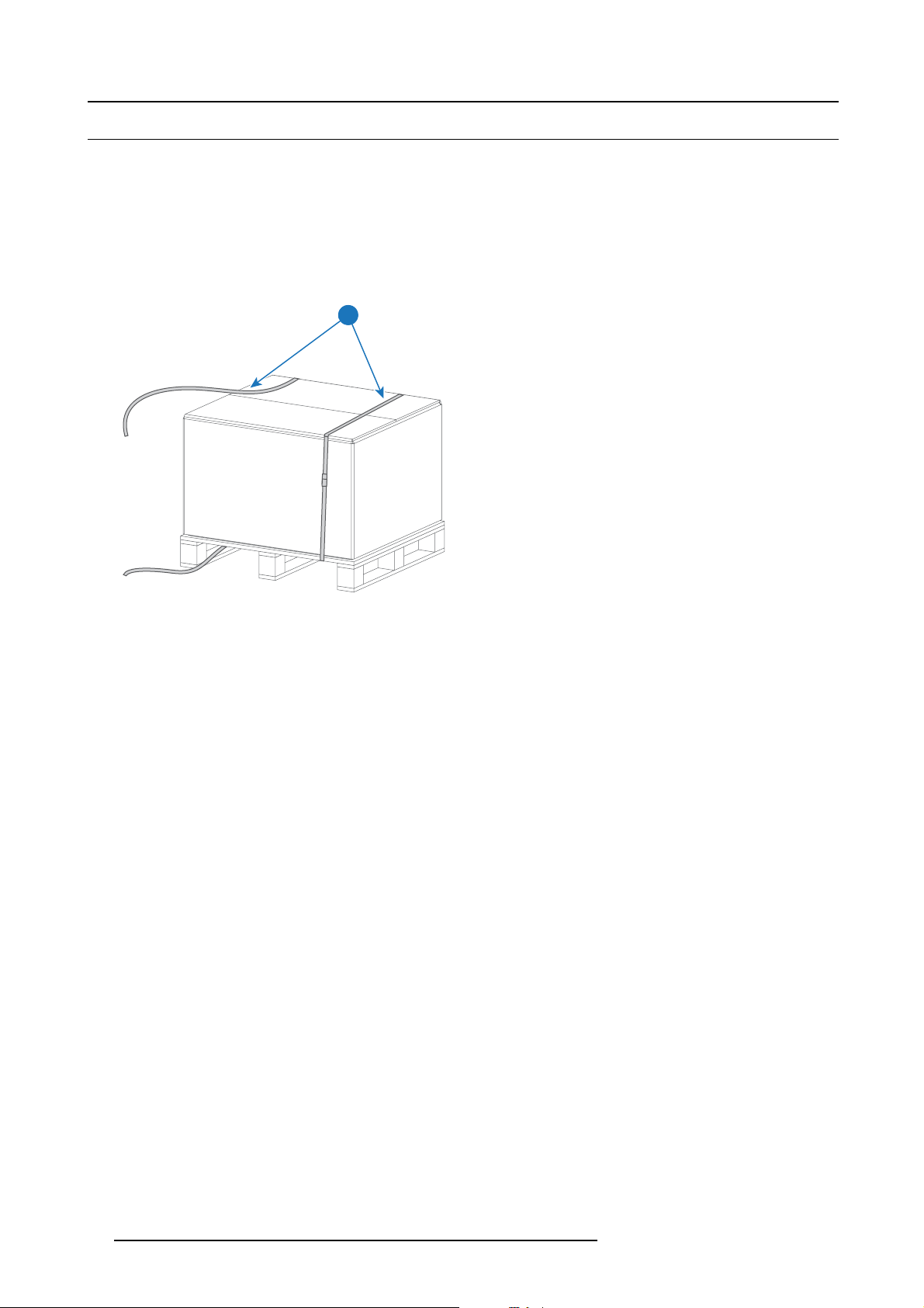
How to unpack your projector?
1. L oosen the banding (1) by pulling the free end of the banding loop in the clip.
1
Image 3-1
2. L ift up the carton box (2) as a whole and remove it away from the projector package.
3. Take out the small box (3) between the polystyrene foam on top of the projec tor. This box contains the product documentation
(manuals etc.).
4. Remove the polystyrene foam (4) from the top of the projector.
18
R5906693 DP2K-E SERIES 19/06/2015

3. Getting started
2
3
4
Image 3-2
5. O pen the plastic bag and lift the projector out of its packaging, using the handles provided in the projector base.
Image 3-3
6. R emov e the plastic cover from the Lens Holder opening.
After unpacking, allow the projector to acclimatize to a room temperature ranging from 10°C (50°F) to
35°C (95°F) MAX. Neglecting this may result in a start up failure of the Light Processor Unit.
R5906693 DP2K-E SERIES 19/06/2015 19
3. Getting started
3.3 Initial inspection
General
Before shipment, the projector was inspected and found to be free of mec hanical and electrical defects. As soon as the projector is
unpacked, inspect for any damage that may have occurred in transit. Save all packing material until the inspection is com pleted. If
damage is found, file claim with ca rrier immediately. The Barco Sales and Service office should be notified as soon as possible.
The p ackaging of the DP2K-E series projector is provided with a shock-watch label. If this shock-watch label
was triggered (red colored at arrival) during transport m ay indicate rough handling by the transpo
In this case, the instructions mentioned on the label, sh ould be followed, which are: adding a note on the “bill
of lading” a nd informing the transport company and the Barco sales and service office as soon as p ossible.
rt company.
Box c ontent
•Projector.
• User and installation m anual (this document).
• Safety manual.
The projector lens is not included in the package of the projector.
Mechanical check
This check should confirm that there are no broken knobs or connectors, that the cabinet and panel surfaces are free of dents and
scratches, and that the operating panel is not scratched or cracked. The Barco Sales and Serv ice office should be notified as soon
as possible if this is not the case.
Tamper l a be l s
During installation please inspect the tamper labels, if they are damaged please contact Barco tech support.
The tamper labels are required by DCI to provide easy visual indication if the equipment was tampered with. T he projectors are
tested and labeled for shipping to ensure that the system was not compromised before reaching the customers final destination.
These tamper labels can be found on the top cover plate from the Light Processor com partment, the side cover plate from the Light
Processor compartment, on the internal c over of the card cage and o
See chapter "Removal and installation of the projector covers", page 119, for instructions on how to remove the projector covers.
n the ICMP.
Image 3-4
Barco tamper label (required for DCI).
20 R5906693 DP2K-E SERIES 19/06/2015

4. Installation process
4. INSTALLATION PROCESS
About this chapter
After you have unpacked and checked the projector, you can start with the installation process of your DP2K-E series projector. This
chapter gives an overview of all the different stages in the installation process which you have to be followed to set your DP2K-E series projector up and running. Each stage is briefly described and refers to more detailed step by step procedures in this manual.
Use this overview as a checklist to ensure that all stages have been followed in the setup process of the DP2K-E series
projector.
Let the projector acclimatize to ambient conditions after unpacking. Neglecting this may result in a startup
failure of the light processor unit.
Overview
• Installation process overview
R5906693 DP2K-E SERIES 19/06/2015
21

4. Installation process
4.1 Installation process overview
Installation process from A to Z
1. C heck if all installation requirements are fulfilled such as the environment conditions of the installation area, electrical facili-
ties, etc. Note that a solid pedestal is required to support the projector. For more info see topic installation requirements.
2. P h ysical installation of the p rojec tor upon its pedestal. See chapter "Positioning the DP2K-E series projector at port w indow ",
page 24.
3. E lectrical connection with the power net. See chapter "Connecting the projector with the power net", pa
4. In stallation of a UPS to the projector electronics (if applicable). See chapter "Con necting a UPS to the projector electronics",
page 28.
5. In stallation o f the lens. First select a lens with appropriate throw r atio covering the screen size and the projector - screen
distance. Then install the lens in the lens holder of the projector. For more information about available lenses, lens selection and
lens installation see chapter "Lenses & Lens selection", page 31.
Caution: The projector is delivered with a plastic cover inside the Lens Holder. Remove the cover prior to installing the lens.
6. In stallation of the ICM P (only in case no ICMP is factory installed).
7. Installation of the Communicator Touch Panel. See chapter "Installing the Touch Panel interface", pa
8. S w itch on the projector. The projector can now be switched on. Place the ON/OFF switch of the projector in the ”I” position.
As a result the projector starts to initialize. The status lights of the projector lights up GREEN once the projector is initialized. In
case the status lights up RED m ay indicate a tamper event during transport. If so, contact Barco customer service.
9. S elect the corresponding lens parameters for the installed lens. See us er guide of the Communicator chapter Installation >
Advanced > Lens parameters.
10.Alignment of the projected image on the screen. The image can be aligned with the sc reen size of the application. Follow
the next steps to achieve that:
a) Press the STANDBY button on the Local Keypad to activate the lamp.
b) Press the DOWSER button on the Local Keypad to open the electronic dowser of the projector. The electronic dowser is open
if the color of the DOWSER button is GREEN.
c) Press the TEST PATTERN button on the Local Keypad to project one of the internal test patterns of the projector on the
screen.
d) Performa“Lens Homing”. See user guide of the Communicator.
e) Use the lens ZOOM, SHIF T and FOCUS buttons on the Local Keypad to match the projected image with the screen. Tilt the
projector in case you can not SHIFT the image completely upon the screen. See
port window", page 24.
See chapter "Local Keypad", page 41, for detailed description of the Local Keypad buttons.
11. Adjusting the light path. Normally the lens holder and the convergence of the projector are perfectly adjusted at the factory.
Nevertheless, some applications require a readjustment of the lens holder, c onvergence or both. See procedure "Scheimpflug
adjustment", page 82, and "Convergence", page 91.
12.Creating screen files, lens files, light sensor calibration (LSC) files, and m acro files for FLAT and for SCOPE. See user
guide of the Communicator.
13.Backup of all projector configuration files. See user g uide of the Communicator.
14.Registration of the projector. The DP2K-E series projector is DCI compliant and should be registered.
15.Projection of a digital cinema movie.
Download the ICMP device certificate, request KDM and DCP from your content supplier, ingest KDM and DCP, and play out the
movie. for detailed instructions see chapter "ICMP", page 47, and user guide of the Communicator and/or (Web) Commander.
Use the Com m unicator (Touch Panel) to configure the applied source. See the user guide of the Communicator (Touch Panel)
for more detailed information.
"Positioning the DP2K-E series projector at
ge 27 .
ge 72.
22
R5906693 DP2K-E SERIES 19/06/2015

5. PHYSICAL INSTALLATION
About this chapter
This chapter describes how the mechanical and electrical set up of your DP2K-E series pr ojector has to be done.
Overview
• Positioning the DP2K-E series projector at port window
• Connecting the projector with the power net
• Connecting a UPS to the projector electronics
5. Physical installation
R5906693 DP2K-E SERIES 19/06/2015
23
5. Physical installation
5.1 Positioning the DP2K-E series projector at port w indow
WARNING: The installation of the DP2K-E series projector requires at least 4 adult persons.
General guidelines
• Use a solid pedestal to mount the DP2K-E series projector on to. Ensure that the pedestal can s upport t
projector and that all feet of the projector are captured.
• The pedestal should be placed in front of the port window wall in a manner such that the projector lens is at a minimum distance
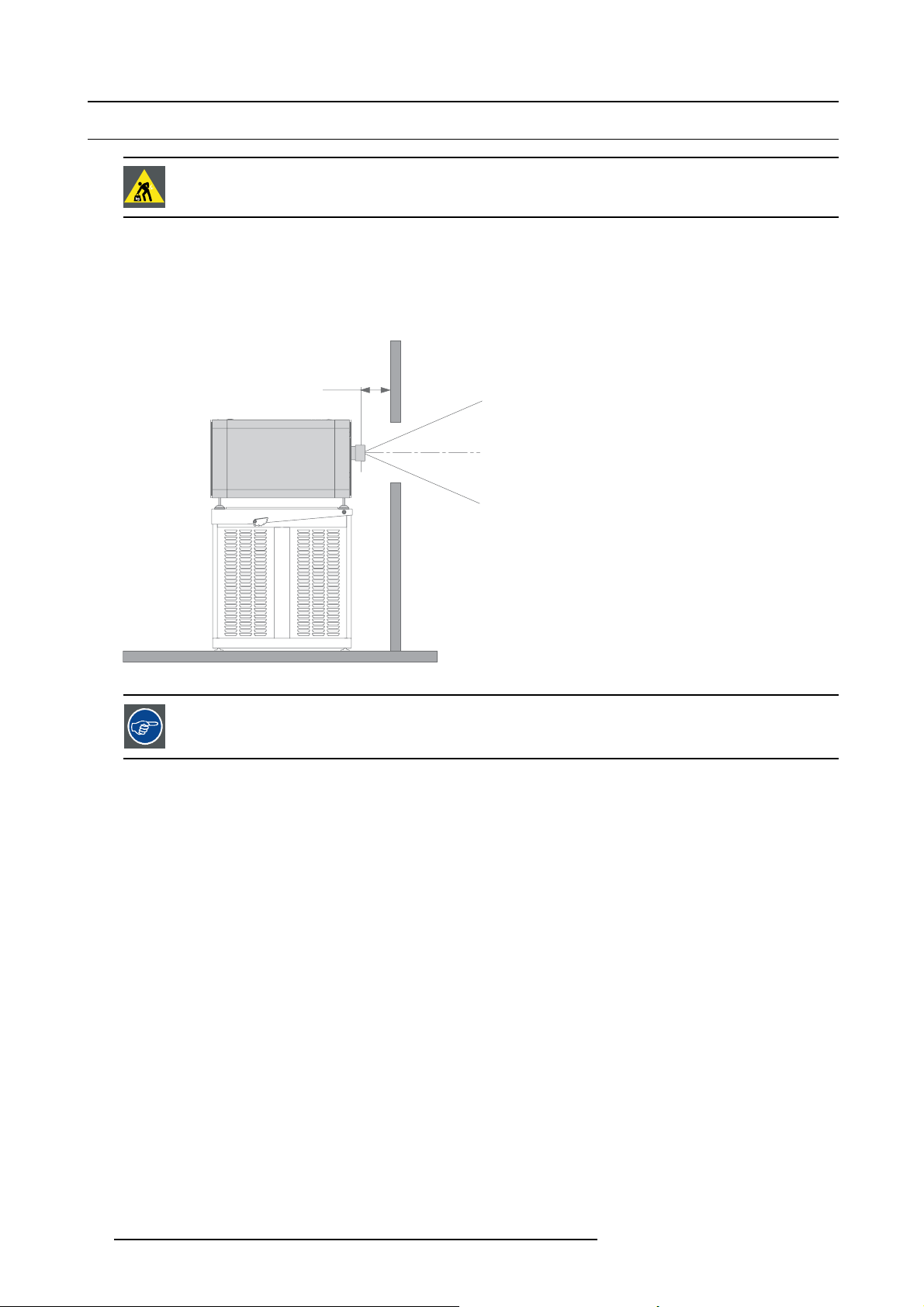
of 20 centimeters from the port window.
20 cm
Image 5-1
Barco offers a pedestal for the DP2K-E series projector. This universal pedestal allows for a solid and easy
setup of the projector. The universal pedestal support 19” rack systems. (pro jector peripherals such as alternative content switchers, ShowVault, etc.)
he weight of the
Necessary tools
• 14mm open end wrench
• 17mm open end wrench
Projector centering
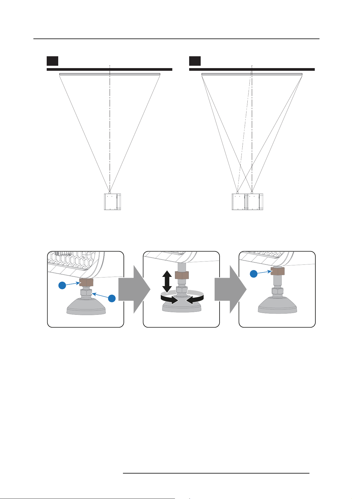
1. If the projector is standalone in front of the port window, center the projector with the theatre screen (A).
2. If an analog film projector is already present (projector will be off-center), try to optimize aim (B).
Note: Unlike analog film projectors, it is best to keep the projector lens surface as parallel as possible to the screen, even if it
is significantly above the screen center.
Caution: The front foot has an adjustment range of maximum 70mm. The back feet maximum 125mm.
24
R5906693 DP2K-E SERIES 19/06/2015
5. Physical installation
The off-center position slightly increases side keystone, but will m inimize horizontal lens offset required.
A B
Image 5-2
3. P roceed to level the projector by adjusting the feet of the projector as follows:
- Loosen the nut (1) on the threaded rod of the three projector feet. Use a 17mm open wrenc h.
- Adjust the height of the 3 legs to level the projector. U se a 14 mm wrench to adjust the height as illustrated (2).
- Secure the leg height by tightening the nuts (1) of each projector foot.
SCREEN CENTER SCREEN CENTER
OFF-CENTER
1
1
2
Image 5-3
4. L ater, when the projector is up-and-running, adjust precise im age geometry and placement.
Projector tilting
In an ideal installation, the DP2K-E series projector lens surface is centered with and parallel to the screen. This orientation helps
to ensure optimized lens performance with minimal offset. If this position is not possible (such as when the projector is signifi cantly
higher than the center of the screen), it is better to rely on offset rather than extra tilt. I n other words, use the SHIFT functionality
of the Lens Holder prior to tilt the projector.
1. B efore adjusting tilt, make s
2. C heck the degree of screen tilt, or measure this incline with a protractor at the screen.
3. Tilt the projector to closely match this screen tilt angle as follows:
- Loosen the nut (1) on the threaded rod of the three projector feet. Use a 17mm open wrenc h.
- Adjust the height of the 3 legs unt
open wrench to adjust the height as illustrated (2).
- Secure the leg height by tightening the nuts (1) of each projector foot.
ure the projector is as well-centered with the theatre screen as possible for the installation area.
il the projected image matches the projection port window and the screen tilt. Use a 14mm
R5906693 DP2K-E SERIES 19/06/2015
25

5. Physical installation
Image 5-4
CAUTION: The DP2K -E series projector may tilt maximum 15° forward and maximum 5° backwards. No tilt is
allowed sideways.
90°
Inclined screen
The b ack feet of the projector can be turned out maximum 125mm.
if the front foot is completely turned in.
Barco offers a p edestal for the DP2K-E series projector. This universal pedestal allows you to easily tilt the
projectorforwardupto6°.
Use the tilt of the projector feet and the pedestal to get sufficient tilt.
This correspond w ith a forward tilt of 12°
26 R5906693 DP2K-E SERIES 19/06/2015
 Loading...