


F90 Series.
User Manual
601–0400/02
10/05/2017
Barco Fredrikstad AS
Habornveien 53, N-1630 Gamle Fredrikstad, Norway Phone: +47 6930 4550
Fax: +47 6930 4580
Support: Support.fre@barco.com Visit us at the web: www.barco.com
Printed in N0
Changes
Barco provides this manual ’as is’ without warranty of any kind, either expressed or implied, including but not limited to the implied warranties or merchantability and fitness for a particular purpose. Barco may make improvements and/or changes to the product(s) and/or the program(s) described in this publication at any time without notice.
This publication could contain technical inaccuracies or typographical errors. Changes are periodically made to the information in this publication; these changes are incorporated in new editions of this publication.
The latest edition of Barco manuals can be downloaded from the Barco web site www.barco.com or from the secured Barco web site https://www.barco.com/en/signin.
Federal Communications Commission (FCC Statement)
This equipment has been tested and found to comply with the limits for a class A digital device, pursuant to Part 15 of the FCC rules. These limits are designed to provide reasonable protection against harmful interference when the equipment is operated in a commercial environment. This equipment generates, uses, and can radiate radio frequency energy and, if not installed and used in accordance with the instruction manual, may cause harmful interference to radio communications. Operation of this equipment in a residential area may cause harmful interference, in which case the user will be responsible for correcting any interference at his own expense
Changes or modifications not expressly approved by the party responsible for compliance could void the user’s authority to operate the equipment
Trademarks
Brand and product names mentioned in this manual may be trademarks, registered trademarks or copyrights of their respective holders. All brand and product names mentioned in this manual serve as comments or examples and are not to be understood as advertising for the products or their manufacturers.
Turkey RoHS compliance
 Türkiye Cumhuriyeti: AEEE Yönetmeliğine Uygundur.
[Republic of Turkey: In conformity with the WEEE Regulation]
Disposal Information
Waste Electrical and Electronic Equipment
 This symbol on the product indicates that, under the European Directive 2012/19/EU governing waste from electrical and electronic equipment, this product must not be disposed of with other municipal waste. Please dispose of your waste equipment by handing it over to a designated collection point for the recycling of waste electrical and electronic equipment. To prevent possible harm to the environment or human health from uncontrolled waste disposal, please separate these items from other types of waste and recycle them responsibly to promote the sustainable reuse of material resources.
For more information about recycling of this product, please contact your local city office or your municipal waste disposal service.
For details, please visit the Barco website at: http://www.barco.com/en/AboutBarco/weee
Disposal of batteries in the product

 This product contains batteries covered by the Directive 2006/66/EC which must be collected and disposed of separately from municipal waste.
If the battery contains more than the specified values of lead (Pb), mercury (Hg) or cadmium (Cd), these chemical symbols will appear below the crossed-out wheeled bin symbol.
By participating in separate collection of batteries, you will help to ensure proper disposal and to prevent potential negative effects on the environment and human health.
Guarantee and Compensation
Barco provides a guarantee relating to perfect manufacturing as part of the legally stipulated terms of guarantee. On receipt, the purchaser must immediately inspect all delivered goods for damage incurred during transport, as well as for material and manufacturing faults Barco must be informed immediately in writing of any complaints.
The period of guarantee begins on the date of transfer of risks, in the case of special systems and software on the date of commissioning, at latest 30 days after the transfer of risks. In the event of justified notice of complaint, Barco can repair the fault or provide a replacement at its own discretion within an appropriate period. If this measure proves to be impossible or unsuccessful, the purchaser can demand a reduction in the purchase price or cancellation of the contract. All other claims, in particular those relating to compensation for direct or indirect damage, and also damage attributed to the operation of software as well as to other services provided by Barco, being a component of the system or independent service, will be deemed invalid provided the damage is not proven to be attributed to the absence of properties guaranteed in writing or due to the intent or gross negligence or part of Barco.
If the purchaser or a third party carries out modifications or repairs on goods delivered by Barco, or if the goods are handled incorrectly, in particular if the systems are operated incorrectly or if, after the transfer of risks, the goods are subject to influences not agreed upon in the contract, all guarantee claims of the purchaser will be rendered invalid. Not included in the guarantee coverage are system failures which are attributed to programs or special electronic circuitry provided by the purchaser, e.g. interfaces. Normal wear as well as normal maintenance are not subject to the guarantee provided by Barco either.
The environmental conditions as well as the servicing and maintenance regulations specified in this manual must be complied with by the customer.
Copyright ©
All rights reserved. No part of this document may be copied, reproduced or translated. It shall not otherwise be recorded, transmitted or stored in a retrieval system without the prior written consent of Barco.
Software License Agreement
You should carefully read the following terms and conditions before using this software. Your use of this software indicates your acceptance of this license agreement and warranty.
Terms and Conditions:
1.No redistribution of the software is allowed.
2.Reverse-Engineering. You may not reverse engineer, decompile, disassemble or alter this software product.
Disclaimer of Warranty:
This software and the accompanying files are sold “as is” and without warranties as to performance or merchantability or any other warranties whether expressed or implied. In no event shall Barco be liable for damage of any kind, loss of data, loss of profits, business interruption or other pecuniary loss arising directly or indirectly. Any liability of the seller will be exclusively limited to replacement of the product or refund of purchase price.

Table of contents
TABLE OF CONTENTS
1. Safety................................................................................................................ 3
1.1 General considerations. . . . . . . . . . . . . . . . . . . . . . . . . . . . . . . . . . . . . . . . . . . . . . . . . . . . . . . . . . . . . . . . . . . . . . . . . . . . . . . . . . . . . . . . . . . . . . . . . . . . . . . . . . . . . . 3 1.2 Important safety instructions . . . . . . . . . . . . . . . . . . . . . . . . . . . . . . . . . . . . . . . . . . . . . . . . . . . . . . . . . . . . . . . . . . . . . . . . . . . . . . . . . . . . . . . . . . . . . . . . . . . . . . . . 5 1.3 Projector Hazard Distances . . . . . . . . . . . . . . . . . . . . . . . . . . . . . . . . . . . . . . . . . . . . . . . . . . . . . . . . . . . . . . . . . . . . . . . . . . . . . . . . . . . . . . . . . . . . . . . . . . . .. . . . . 7 1.4 High Brightness Precautions . . . . . . . . . . . . . . . . . . . . . . . . . . . . . . . . . . . . . . . . . . . . . . . . . . . . . . . . . . . . . . . . . . . . . . . . . . . . . . . . . . . . . . . . . . . . . . . . . . .. . . . . 7 1.5 Hazard Distance for fully closed projection system . . . . . . . . . . . . . . . . . . . . . . . . . . . . . . . . . . . . . . . . . . . . . . . . . . . . . . . . . . . . . . . . . . . . . . . . . . . . . . . . 9 1.6 HD in function of the lens Throw Ratio (TR) . . . . . . . . . . . . . . . . . . . . . . . . . . . . . . . . . . . . . . . . . . . . . . . . . . . . . . . . . . . . . . . . . . . . . . . . . . . . . . . . . . . . . . . . 10 1.7 Safety symbols . . . . . . . . . . . . . . . . . . . . . . . . . . . . . . . . . . . . . . . . . . . . . . . . . . . . . . . . . . . . . . . . . . . . . . . . . . . . . . . . . . . . . . . . . . . . . . . . . . . . . . . . . . . . . . .. . . . . . . 11 1.8 RoHS compliance . . . . . . . . . . . . . . . . . . . . . . . . . . . . . . . . . . . . . . . . . . . . . . . . . . . . . . . . . . . . . . . . . . . . . . . . . . . . . . . . . . . . . . . . . . . . . . . . . . . . . . . . . . . . . .. . . . . 13 1.9 Contact adresses . . . . . . . . . . . . . . . . . . . . . . . . . . . . . . . . . . . . . . . . . . . . . . . . . . . . . . . . . . . . . . . . . . . . . . . . . . . . . . . . . . . . . . . . . . . . . . . . . . . . . . . . . . . . .. . . . . . . 16 1.10 Product Info . .. . . . . . . . . . . . . . . . . . . . . . . . . . . . . . . . . . . . . . . . . . . . . . . . . . . . . . . . . . . . . . . . . . . . . . . . . . . . . . . . . . . . . . . . . . . . . . . . . . . . . . . . . . . . . . . . . . . . . . . . 16 1.11 Statement . . . . . . . . . . . . . . . . . . . . . . . . . . . . . . . . . . . . . . . . . . . . . . . . . . . . . . . . . . . . . . . . . . . . . . . . . . . . . . . . . . . . . . . . . . . . . . . . . . . . . . . . . . . . . . . . . . . . . . . . . . . . 16
2. Getting to know the projector ...................................................................................17
2.1 Main components. . .. . . . . . . . . . . . . . . . . . . . . . . . . . . . . . . . . . . . . . . . . . . . . . . . . . . . . . . . . . . . . . . . . . . . . . . . . . . . . . . . . . . . . . . . . . . . . . . . . . . . . . . . . . . . . . . . . 17 2.2 Service and maintenance . .. . . . . . . . . . . . . . . . . . . . . . . . . . . . . . . . . . . . . . . . . . . . . . . . . . . . . . . . . . . . . . . . . . . . . . . . . . . . . . . . . . . . . . . . . . . . . . . . . . . . . . . . . 18 2.3 LED status light . . . . . . . . . . . . . . . . . . . . . . . . . . . . . . . . . . . . . . . . . . . . . . . . . . . . . . . . . . . . . . . . . . . . . . . . . . . . . . . . . . . . . . . . . . . . . . . . . . . . . . . . . . . . . .. . . . . . . . 18 2.4 Power on / Standby button backlight indications . . . . . . . . . . . . . . . . . . . . . . . . . . . . . . . . . . . . . . . . . . . . . . . . . . . . . . . . . . . . . . . . . . . . . . . . . . . . . . . . . . . 18 2.5 LCD panel . . .. . . . . . . . . . . . . . . . . . . . . . . . . . . . . . . . . . . . . . . . . . . . . . . . . . . . . . . . . . . . . . . . . . . . . . . . . . . . . . . . . . . . . . . . . . . . . . . . . . . . . . . . . . . . . . . . . . . . . . . . 19 2.6 Local keypad. . . . . . . . . . . . . . . . . . . . . . . . . . . . . . . . . . . . . . . . . . . . . . . . . . . . . . . . . . . . . . . . . . . . . . . . . . . . . . . . . . . . . . . . . . . . . . . . . . . . . . . . . . . . . . . . .. . . . . . . . 19 2.7 Remote control, Battery installation. . . . . . . . . . . . . . . . . . . . . . . . . . . . . . . . . . . . . . . . . . . . . . . . . . . . . . . . . . . . . . . . . . . . . . . . . . . . . . . . . . . . . . . . . . .. . . . . . 20 2.8 Remote control, protocol setup . . . . . . . . . . . . . . . . . . . . . . . . . . . . . . . . . . . . . . . . . . . . . . . . . . . . . . . . . . . . . . . . . . . . . . . . . . . . . . . . . . . . . . . . . . . . . . . . .. . . . 21 2.9 Functionality overview . . . . . . . . . . . . . . . . . . . . . . . . . . . . . . . . . . . . . . . . . . . . . . . . . . . . . . . . . . . . . . . . . . . . . . . . . . . . . . . . . . . . . . . . . . . . . . . . . . . . . . . . . . . . . . . 22 2.10 Projector Address. . . . . . . . . . . . . . . . . . . . . . . . . . . . . . . . . . . . . . . . . . . . . . . . . . . . . . . . . . . . . . . . . . . . . . . . . . . . . . . . . . . . . . . . . . . . . . . . . . . . . . . . . . .. . . . . . . . . 22
2.10.1 Controlling the projector . . . . . . . . . . . . . . . . . . . . . . . . . . . . . . . . . . . . . . . . . . . . . . . . . . . . . . . . . . . . . . . . . . . . . . . . . . . . . . . . . . . . . . . . . . . . . . . . . .. . . . 22 2.10.2 Displaying and Programming addresses into the RCU. .. . . . . . . . . . . . . . . . . . . . . . . . . . . . . . . . . . . . . . . . . . . . . . . . . . . . . . . . . . . . . . . . . . . . 23 2.11 Connector panel . . . . . . . . . . . . . . . . . . . . . . . . . . . . . . . . . . . . . . . . . . . . . . . . . . . . . . . . . . . . . . . . . . . . . . . . . . . . . . . . . . . . . . . . . . . . . . . . . . . . . . . . . . . . . . . . . . . . . 23 2.12 Color Wheels . . . . . . . . . . . . . . . . . . . . . . . . . . . . . . . . . . . . . . . . . . . . . . . . . . . . . . . . . . . . . . . . . . . . . . . . . . . . . . . . . . . . . . . . . . . . . . . . . . . . . . . . . . . . . . . . . . . . . . . . 24 2.12.1 Color Wheel range . . .. . . . . . . . . . . . . . . . . . . . . . . . . . . . . . . . . . . . . . . . . . . . . . . . . . . . . . . . . . . . . . . . . . . . . . . . . . . . . . . . . . . . . . . . . . . . . . . . . . . . . . . . . 24 2.12.2 Change the color wheel . . . . . . . . . . . . . . . . . . . . . . . . . . . . . . . . . . . . . . . . . . . . . . . . . . . . . . . . . . . . . . . . . . . . . . . . . . . . . . . . . . . . . . . . . . . . . . . . . . . . . . 24 2.13 Optional accessories . . . . . . . . . . . . . . . . . . . . . . . . . . . . . . . . . . . . . . . . . . . . . . . . . . . . . . . . . . . . . . . . . . . . . . . . . . . . . . . . . . . . . . . . . . . . . . . . . . . . . . . . . . . . . . . . 25
3. Lenses...............................................................................................................27
3.1 Approved Lenses . . .. . . . . . . . . . . . . . . . . . . . . . . . . . . . . . . . . . . . . . . . . . . . . . . . . . . . . . . . . . . . . . . . . . . . . . . . . . . . . . . . . . . . . . . . . . . . . . . . . . . . . . . . . . . . . . . . . 27 3.2 Lens range . . .. . . . . . . . . . . . . . . . . . . . . . . . . . . . . . . . . . . . . . . . . . . . . . . . . . . . . . . . . . . . . . . . . . . . . . . . . . . . . . . . . . . . . . . . . . . . . . . . . . . . . . . . . . . . . . . . . . . . . . . . 27 3.3 Replace a lens . . . . . . . . . . . . . . . . . . . . . . . . . . . . . . . . . . . . . . . . . . . . . . . . . . . . . . . . . . . . . . . . . . . . . . . . . . . . . . . . . . . . . . . . . . . . . . . . . . . . . . . . . . . . . . . .. . . . . . . 29 3.4 Lens shift. . . . . . . . . . . . . . . . . . . . . . . . . . . . . . . . . . . . . . . . . . . . . . . . . . . . . . . . . . . . . . . . . . . . . . . . . . . . . . . . . . . . . . . . . . . . . . . . . . . . . . . . . . . . . . . . . . . . . . . . . . . . . 31 3.5 Adjust zoom, focus and iris. . . . . . . . . . . . . . . . . . . . . . . . . . . . . . . . . . . . . . . . . . . . . . . . . . . . . . . . . . . . . . . . . . . . . . . . . . . . . . . . . . . . . . . . . . . . . . . . . . . . .. . . . . 31
4. Physical installation ..............................................................................................33
4.1 Installation process . . . . . . . . . . . . . . . . . . . . . . . . . . . . . . . . . . . . . . . . . . . . . . . . . . . . . . . . . . . . . . . . . . . . . . . . . . . . . . . . . . . . . . . . . . . . . . . . . . . . . . . . .. . . . . . . . . 33 4.2 Installation conditions . . . . . . . . . . . . . . . . . . . . . . . . . . . . . . . . . . . . . . . . . . . . . . . . . . . . . . . . . . . . . . . . . . . . . . . . . . . . . . . . . . . . . . . . . . . . . . . . . . . . . . . . . . . . . . . 33 4.3 Initial inspection. . . . . . . . . . . . . . . . . . . . . . . . . . . . . . . . . . . . . . . . . . . . . . . . . . . . . . . . . . . . . . . . . . . . . . . . . . . . . . . . . . . . . . . . . . . . . . . . . . . . . . . . . . .. . . . . . . . . . . 35 4.4 Positioning the projector. . . . . . . . . . . . . . . . . . . . . . . . . . . . . . . . . . . . . . . . . . . . . . . . . . . . . . . . . . . . . . . . . . . . . . . . . . . . . . . . . . . . . . . . . . . . . . . . . . . . .. . . . . . . . 36 4.5 Mounting the projector, general considerations .. . . . . . . . . . . . . . . . . . . . . . . . . . . . . . . . . . . . . . . . . . . . . . . . . . . . . . . . . . . . . . . . . . . . . . . . . . . . . . . . . . . 36 4.6 Projector safe attachment points. . . . . . . . . . . . . . . . . . . . . . . . . . . . . . . . . . . . . . . . . . . . . . . . . . . . . . . . . . . . . . . . . . . . . . . . . . . . . . . . . . . . . . . . . . . . . . .. . . . . 38 4.7 Throw distance . . . . . . . . . . . . . . . . . . . . . . . . . . . . . . . . . . . . . . . . . . . . . . . . . . . . . . . . . . . . . . . . . . . . . . . . . . . . . . . . . . . . . . . . . . . . . . . . . . . . . . . . . . . . . . .. . . . . . . 38 4.8 Scheimpflug (Boresight) adjustment . . . . . . . . . . . . . . . . . . . . . . . . . . . . . . . . . . . . . . . . . . . . . . . . . . . . . . . . . . . . . . . . . . . . . . . . . . . . . . . . . . . . . . . . . . . . . . . . 41 4.9 Scheimpflug adjustment procedure . . . . . . . . . . . . . . . . . . . . . . . . . . . . . . . . . . . . . . . . . . . . . . . . . . . . . . . . . . . . . . . . . . . . . . . . . . . . . . . . . . . . . . . . . . . . . . . . . 42
5. Getting started .....................................................................................................45
5.1 Projector source and control connections . . . . . . . . . . . . . . . . . . . . . . . . . . . . . . . . . . . . . . . . . . . . . . . . . . . . . . . . . . . . . . . . . . . . . . . . . . . . . . . . . . . . . . . . . . 45 5.1.1 Making connections. .. . . . . . . . . . . . . . . . . . . . . . . . . . . . . . . . . . . . . . . . . . . . . . . . . . . . . . . . . . . . . . . . . . . . . . . . . . . . . . . . . . . . . . . . . . . . . . . . . . . . . . . . . 45 5.1.2 Connector specifications. . . . . . . . . . . . . . . . . . . . . . . . . . . . . . . . . . . . . . . . . . . . . . . . . . . . . . . . . . . . . . . . . . . . . . . . . . . . . . . . . . . . . . . . . . . . . . . . . . . . . . 45 5.1.2.1 DVI-I . . . . . . . . . . . . . . . . . . . . . . . . . . . . . . . . . . . . . . . . . . . . . . . . . . . . . . . . . . . . . . . . . . . . . . . . . . . . . . . . . . . . . . . . . . . . . . . . . . . . . . . . . . . . . . . . . . .. 45 5.1.2.2 Display Port 1.2 . . . . . . . . . . . . . . . . . . . . . . . . . . . . . . . . . . . . . . . . . . . . . . . . . . . . . . . . . . . . . . . . . . . . . . . . . . . . . . . . . . . . . . . . . . . . . . . . . . . . . . . . 46 5.1.2.3 HDMI 2.0. . . . . . . . . . . . . . . . . . . . . . . . . . . . . . . . . . . . . . . . . . . . . . . . . . . . . . . . . . . . . . . . . . . . . . . . . . . . . . . . . . . . . . . . . . . . . . . . . . . . . . . . . . . . . . . . 46 5.1.2.4 3G-SDI. . . . . . . . . . . . . . . . . . . . . . . . . . . . . . . . . . . . . . . . . . . . . . . . . . . . . . . . . . . . . . . . . . . . . . . . . . . . . . . . . . . . . . . . . . . . . . . . . . . . . . . . . . . . . . . . . . 47 5.1.2.5 HDBase T. . . . . . . . . . . . . . . . . . . . . . . . . . . . . . . . . . . . . . . . . . . . . . . . . . . . . . . . . . . . . . . . . . . . . . . . . . . . . . . . . . . . . . . . . . . . . . . . . . . . . . . . . . . . . . . 47 5.1.3 Control interfaces . . . . . . . . . . . . . . . . . . . . . . . . . . . . . . . . . . . . . . . . . . . . . . . . . . . . . . . . . . . . . . . . . . . . . . . . . . . . . . . . . . . . . . . . . . . . . . . . . . . . . . . . .. . . . 47 5.1.3.1 RS-232. . . . . . . . . . . . . . . . . . . . . . . . . . . . . . . . . . . . . . . . . . . . . . . . . . . . . . . . . . . . . . . . . . . . . . . . . . . . . . . . . . . . . . . . . . . . . . . . . . . . . . . . . . . . . . . . . . 48 5.1.3.2 LAN/Ethernet . . . . . . . . . . . . . . . . . . . . . . . . . . . . . . . . . . . . . . . . . . . . . . . . . . . . . . . . . . . . . . . . . . . . . . . . . . . . . . . . . . . . . . . . . . . . . . . . . . . . . . . . . . . 48 5.1.3.3 USB-A port . . . . . . . . . . . . . . . . . . . . . . . . . . . . . . . . . . . . . . . . . . . . . . . . . . . . . . . . . . . . . . . . . . . . . . . . . . . . . . . . . . . . . . . . . . . . . . . . . . . . . . . . . . . . . 48
5.2 Power up the projector . . . . . . . . . . . . . . . . . . . . . . . . . . . . . . . . . . . . . . . . . . . . . . . . . . . . . . . . . . . . . . . . . . . . . . . . . . . . . . . . . . . . . . . . . . . . . . . . . . . . . . . . .. . . . . 48 5.3 Power down the projector . . . . . . . . . . . . . . . . . . . . . . . . . . . . . . . . . . . . . . . . . . . . . . . . . . . . . . . . . . . . . . . . . . . . . . . . . . . . . . . . . . . . . . . . . . . . . . . . . . . . . . .. . . . 48 5.4 Power modes . . . . . . . . . . . . . . . . . . . . . . . . . . . . . . . . . . . . . . . . . . . . . . . . . . . . . . . . . . . . . . . . . . . . . . . . . . . . . . . . . . . . . . . . . . . . . . . . . . . . . . . . . . . . . . . . . . . . . . . . 49 5.5 Customize projector settings . . . . . . . . . . . . . . . . . . . . . . . . . . . . . . . . . . . . . . . . . . . . . . . . . . . . . . . . . . . . . . . . . . . . . . . . . . . . . . . . . . . . . . . . . . . . . . . . . .. . . . . . 49 5.6 User interface. . . . . . . . . . . . . . . . . . . . . . . . . . . . . . . . . . . . . . . . . . . . . . . . . . . . . . . . . . . . . . . . . . . . . . . . . . . . . . . . . . . . . . . . . . . . . . . . . . . . . . . . . . . . . . .. . . . . . . . . 49
5.6.1 On Screen Display (OSD) . . . . . . . . . . . . . . . . . . . . . . . . . . . . . . . . . . . . . . . . . . . . . . . . . . . . . . . . . . . . . . . . . . . . . . . . . . . . . . . . . . . . . . . . . . . . . . . . . . . . 49
6. Source menu .......................................................................................................51
6.1 Connector selection . . . . . . . . . . . . . . . . . . . . . . . . . . . . . . . . . . . . . . . . . . . . . . . . . . . . . . . . . . . . . . . . . . . . . . . . . . . . . . . . . . . . . . . . . . . . . . . . . . . . . . . . . . . . . . . . . 51 6.2 Connector Settings .. . . . . . . . . . . . . . . . . . . . . . . . . . . . . . . . . . . . . . . . . . . . . . . . . . . . . . . . . . . . . . . . . . . . . . . . . . . . . . . . . . . . . . . . . . . . . . . . . . . . . . . . . . . . . . . . . 51
601–0400 F90 SERIES. 10/05/2017 |
|
1 |

Table of contents
6.3 Using Dual DVI or Dual Display Port. . . . . . . . . . . . . . . . . . . . . . . . . . . . . . . . . . . . . . . . . . . . . . . . . . . . . . . . . . . . . . . . . . . . . . . . . . . . . . . . . . . . . . . . . . . . . . .. 51
7. Image menu ........................................................................................................53
7.1 Output Resolution . . . . . . . . . . . . . . . . . . . . . . . . . . . . . . . . . . . . . . . . . . . . . . . . . . . . . . . . . . . . . . . . . . . . . . . . . . . . . . . . . . . . . . . . . . . . . . . . . . . . . . . . . . . .. . . . . . . 53 7.2 Contrast . . . . . . . . . . . . . . . . . . . . . . . . . . . . . . . . . . . . . . . . . . . . . . . . . . . . . . . . . . . . . . . . . . . . . . . . . . . . . . . . . . . . . . . . . . . . . . . . . . . . . . . . . . . . . . . . . . . .. . . . . . . . . . 53 7.3 Brightness . . . . . . . . . . . . . . . . . . . . . . . . . . . . . . . . . . . . . . . . . . . . . . . . . . . . . . . . . . . . . . . . . . . . . . . . . . . . . . . . . . . . . . . . . . . . . . . . . . . . . . . . . . . . . . . . . .. . . . . . . . . 53 7.4 Saturation . . . . . . . . . . . . . . . . . . . . . . . . . . . . . . . . . . . . . . . . . . . . . . . . . . . . . . . . . . . . . . . . . . . . . . . . . . . . . . . . . . . . . . . . . . . . . . . . . . . . . . . . . . . . . . . . . .. . . . . . . . . . 53 7.5 Advanced image adjustments. . . . . . . . . . . . . . . . . . . . . . . . . . . . . . . . . . . . . . . . . . . . . . . . . . . . . . . . . . . . . . . . . . . . . . . . . . . . . . . . . . . . . . . . . . . . . . . . . . . . . . . 53
8. Installation menu ..................................................................................................55
8.1 Lens . .. . . . . . . . . . . . . . . . . . . . . . . . . . . . . . . . . . . . . . . . . . . . . . . . . . . . . . . . . . . . . . . . . . . . . . . . . . . . . . . . . . . . . . . . . . . . . . . . . . . . . . . . . . . . . . . . . . . . . . . . . . . . . . .. 55 8.2 Orientation . . . . . . . . . . . . . . . . . . . . . . . . . . . . . . . . . . . . . . . . . . . . . . . . . . . . . . . . . . . . . . . . . . . . . . . . . . . . . . . . . . . . . . . . . . . . . . . . . . . . . . . . . . . . . . . . .. . . . . . . . . . 55 8.3 Warp . . . . . . . . . . . . . . . . . . . . . . . . . . . . . . . . . . . . . . . . . . . . . . . . . . . . . . . . . . . . . . . . . . . . . . . . . . . . . . . . . . . . . . . . . . . . . . . . . . . . . . . . . . . . . . . . . . . . . . . .. . . . . . . . . 56 8.4 Basic Blend . . . . . . . . . . . . . . . . . . . . . . . . . . . . . . . . . . . . . . . . . . . . . . . . . . . . . . . . . . . . . . . . . . . . . . . . . . . . . . . . . . . . . . . . . . . . . . . . . . . . . . . . . . . . . . . . . .. . . . . . . . 57 8.5 Illumination. . . . . . . . . . . . . . . . . . . . . . . . . . . . . . . . . . . . . . . . . . . . . . . . . . . . . . . . . . . . . . . . . . . . . . . . . . . . . . . . . . . . . . . . . . . . . . . . . . . . . . . . . . . . . . . .. . . . . . . . . . . 59
9. Settings menu......................................................................................................61
9.1 Communication . . . . . . . . . . . . . . . . . . . . . . . . . . . . . . . . . . . . . . . . . . . . . . . . . . . . . . . . . . . . . . . . . . . . . . . . . . . . . . . . . . . . . . . . . . . . . . . . . . . . . . . . . . . . . . . . . . . . . . 61 9.2 Apply a menu theme . . . . . . . . . . . . . . . . . . . . . . . . . . . . . . . . . . . . . . . . . . . . . . . . . . . . . . . . . . . . . . . . . . . . . . . . . . . . . . . . . . . . . . . . . . . . . . . . . . . . . . . . . . . . . . . . 61 9.3 Service . . . . . . . . . . . . . . . . . . . . . . . . . . . . . . . . . . . . . . . . . . . . . . . . . . . . . . . . . . . . . . . . . . . . . . . . . . . . . . . . . . . . . . . . . . . . . . . . . . . . . . . . . . . . . . . . . . . . .. . . . . . . . . . 61
10. Status menu ........................................................................................................63
10.1 Source status . . . . . . . . . . . . . . . . . . . . . . . . . . . . . . . . . . . . . . . . . . . . . . . . . . . . . . . . . . . . . . . . . . . . . . . . . . . . . . . . . . . . . . . . . . . . . . . . . . . . . . . . . . . . . . .. . . . . . . . . 63 10.2 Product. . . . . . . . . . . . . . . . . . . . . . . . . . . . . . . . . . . . . . . . . . . . . . . . . . . . . . . . . . . . . . . . . . . . . . . . . . . . . . . . . . . . . . . . . . . . . . . . . . . . . . . . . . . . . . . . . . . . . . . . . . . . . . . 63 10.3 Illumination. . . . . . . . . . . . . . . . . . . . . . . . . . . . . . . . . . . . . . . . . . . . . . . . . . . . . . . . . . . . . . . . . . . . . . . . . . . . . . . . . . . . . . . . . . . . . . . . . . . . . . . . . . . . . . .. . . . . . . . . . . . 63 10.4 Communication . . . . . . . . . . . . . . . . . . . . . . . . . . . . . . . . . . . . . . . . . . . . . . . . . . . . . . . . . . . . . . . . . . . . . . . . . . . . . . . . . . . . . . . . . . . . . . . . . . . . . . . . . . . . . . . . . . . . . . 63
11. Reset Menu .........................................................................................................65
11.1 Factory Reset . . . . . . . . . . . . . . . . . . . . . . . . . . . . . . . . . . . . . . . . . . . . . . . . . . . . . . . . . . . . . . . . . . . . . . . . . . . . . . . . . . . . . . . . . . . . . . . . . . . . . . . . . . . . . . .. . . . . . . . . 65
11.2 Selectable Reset . . . . . . . . . . . . . . . . . . . . . . . . . . . . . . . . . . . . . . . . . . . . . . . . . . . . . . . . . . . . . . . . . . . . . . . . . . . . . . . . . . . . . . . . . . . . . . . . . . . . . . . . . . . .. . . . . . . . 65
12. User Maintenance .................................................................................................67
12.1 Update Projector Firmware.. . . . . . . . . . . . . . . . . . . . . . . . . . . . . . . . . . . . . . . . . . . . . . . . . . . . . . . . . . . . . . . . . . . . . . . . . . . . . . . . . . . . . . . . . . . . . . . . . . . . . . . . . 67
13. Cleaning the projector............................................................................................69
13.1 Projector lenses . . . . . . . . . . . . . . . . . . . . . . . . . . . . . . . . . . . . . . . . . . . . . . . . . . . . . . . . . . . . . . . . . . . . . . . . . . . . . . . . . . . . . . . . . . . . . . . . . . . . . . . . . . . .. . . . . . . . . 69 13.2 Projector cabinet. . . . . . . . . . . . . . . . . . . . . . . . . . . . . . . . . . . . . . . . . . . . . . . . . . . . . . . . . . . . . . . . . . . . . . . . . . . . . . . . . . . . . . . . . . . . . . . . . . . . . . . . . . .. . . . . . . . . . 69 13.3 Filters . . . . . . . . . . . . . . . . . . . . . . . . . . . . . . . . . . . . . . . . . . . . . . . . . . . . . . . . . . . . . . . . . . . . . . . . . . . . . . . . . . . . . . . . . . . . . . . . . . . . . . . . . . . . . . . . . . . .. . . . . . . . . . . . 69
2 |
|
601–0400 F90 SERIES. 10/05/2017 |

1. Safety
1. SAFETY
About this chapter
Read this chapter thoroughly before attempting to install or operate the projector.
To prevent personal injury to users or physical damage to the projector while installing and using your projector, ensure that you understand and follow all safety guidelines, instructions and warnings included in this chapter and this manual.
Clarification of the term F70 / F90 series used in this document
Use in this document of the term, F70 / F90 series, means that the content is applicable for the following products:
•F90–W13WUXGA
•F90–4K13 4KUHD/WQXGA
•F70 — 4K6
•F70 — W6
Defining the GP6 platform
The F90 series products in general, are all products within the Barco GP6 Platform.
Defining the GP7 platform
The F70 series products in general, are all products within the Barco GP7 Platform
Overview
•General considerations
•Important safety instructions
•Projector Hazard Distances
•High Brightness Precautions
•Hazard Distance for fully closed projection system
•HD in function of the lens Throw Ratio (TR)
•Safety symbols
•RoHS compliance
•Contact adresses
•Product Info
•Statement
1.1General considerations
Notice on optical radiation F90 Series
•The projector is Class 1 laser product that conforms with IEC EN 60825-1:2014. For Northern America, the projector is class 3R laser product up to throw ratio 2.33. The projector conforms with IEC 60825–1:2007, and with performance standards for laser products under 21 CFR 1040, except with respect to those characteristics authorized by Variance Number 2016–V-0144 effective March 6, 2017
Do not stare into Beam.
•This projector is Risk Group 2 (RG2) according to IEC EN 62471-5.
This projector may become Risk Group 3 (RG3) when an interchangeable lens with throw ratio greater than 3.15 is installed. For Northern America, installation requirements according to Risk group 3 (RG3) must be followed when interchangeable lens with throw ratio greater than 2.33 is installed.
Refer to the manual for the lens list and throw ratio before operation.
Such combination of projector and lens are intended for professional use only, and are not intended for consumer use.
•For RG3, no direct exposure to the beam shall be permitted.
For RG3, operators shall control access to the beam within the hazard distance or install the product at a height that will prevent eye exposure within the hazard distance.
•This projector has two (2) built-in Class 4 laser clusters. Disassembly or modification is very dangerous and should never be attempted.
•Any operation or adjustment not specifically instructed by the user’s guide creates the risk of hazardous laser radiation exposure.
•Do not open or disassemble the projector as this may cause damage by the exposure of laser radiation.
601–0400 F90 SERIES. 10/05/2017 |
|
3 |

1. Safety
Notice on optical radiation F70 Series
•The projector is Class 1 laser product that conforms with IEC EN 60825-1:2014. For Northern America, the projector is class 3R laser product up to throw ratio 2.5. The projector conforms with IEC 60825–1:2007, and with performance standards for laser products under 21 CFR 1040, except with respect to those characteristics authorized by Variance Number 2016–V-0144 effective March 6, 2017
Do not stare into Beam.
•This projector is Risk Group 2 (RG2) according to IEC EN 62471-5.
This projector may become Risk Group 3 (RG3) when an interchangeable lens with throw ratio greater than 4.7 is installed. For Northern America, installation requirements according to Risk group 3 (RG3) must be followed when interchangeable lens with throw ratio greater than 2.5 is installed.
Refer to the manual for the lens list and throw ratio before operation.
Such combination of projector and lens are intended for professional use only, and are not intended for consumer use.
•For RG3, no direct exposure to the beam shall be permitted.
For RG3, operators shall control access to the beam within the hazard distance or install the product at a height that will prevent eye exposure within the hazard distance.
•This projector has one (1) built-in Class 4 laser clusters. Disassembly or modification is very dangerous and should never be attempted.
•Any operation or adjustment not specifically instructed by the user’s guide creates the risk of hazardous laser radiation exposure.
•Do not open or disassemble the projector as this may cause damage by the exposure of laser radiation.
General safety instructions
•This product contains no user serviceable parts except the Color Wheel. Attempts to modify/replace mechanics or electronics inside the housing or compartments will violate any warranties and may be hazardous.
Do not remove/replace any other parts than the Color Wheel. Other parts, service personnel only – Warranty void if Removed. Follow the instructions in the User Guide to replace the Color Wheel.
•Do not stare into beam when the projector is on. The bright light may result in permanent eye damage.
•Not following the prescribed control, adjustment or operation procedure may cause damage by the exposure of laser radiation.
•Before operating this equipment please read this manual thoroughly and retain it for future reference.
•Installation and preliminary adjustments should be performed by properly trained and qualified personnel.
•All warnings on the projector and in the documentation manuals must be adhered to.
•All instructions for operating and use of this equipment must be followed precisely.
•All local installation codes should be adhered to.
Notice on safety
This equipment is built in accordance with the requirements of the international safety standards IEC60950-1, as basis for National safety regulation world wide. The safety standard covers information technology equipment including electrical business equipment intended to operate in “normal” environments (offices and homes). This safety standard imposes important requirements on the use of safety critical components, materials and insulation, in order to protect the user or operator against risk of electric shock and energy hazard and having access to live parts. Safety standards also impose limits to the internal and external temperature rises, radiation levels, mechanical stability and strength, enclosure construction and protection against the risk of fire. Simulated single fault condition testing reduce the risk of hazards and contribute to ensure the safety of the equipment to the user even when the equipment’s normal operation fails.
Users definition
Throughout this manual, the term SERVICE PERSONNEL refers to Barco authorized persons having appropriate technical training and experience necessary to be knowledgeable of potential hazards to which they are exposed (including, but not limited to HIGH VOLTAGE ELECTRIC and ELECTRONIC CIRCUITRY and HIGH BRIGHTNESS PROJECTORS) in performing a task, and of measures to minimize the potential risk to themselves or other persons. Only Barco authorized SERVICE PERSONNEL, knowledgeable of such risks, are allowed to perform service functions inside the product enclosure. The term USER and OPERATOR refers to any person other than SERVICE PERSONNEL. When an interchangeable lens with throw ratio 3.15 or more is installed, the F70 / F90 series projector becomes RG3. Refer to the manual for the lens list and hazard distance before operation. Such combination of projector and lens are intended for professional use only, and are not intended for consumer use.
FOR PROFESSIONAL USE ONLY means installation can only be carried out by Barco AUTHORIZED PERSONNEL familiar with potential hazards associated with high intensity light beams.
4 |
|
601–0400 F90 SERIES. 10/05/2017 |

1. Safety
1.2Important safety instructions
To prevent the risk of electrical shock
•This product should be operated from a mono phase AC power source.
•This apparatus must be grounded (earthed) via the supplied 3 conductor AC power cable. If none of the supplied power cables are the correct one, consult your dealer.
If you are unable to insert the plug into the outlet, contact your electrician to replace your obsolete outlet. Do not defeat the purpose of the grounding-type plug.
Never use 2-prong power cords, as this is dangerous and could lead to electrical shock.
•Do not allow anything to rest on the power cord. Do not locate this product where persons will walk on the cord. To disconnect the cord, pull it out by the plug. Never pull the cord itself.
•Use only the power cord supplied with your device or original replacement cords. While appearing to be similar, other power cords have not been safety tested at the factory and may not be used to power the device. For a replacement power cord, contact your dealer.
•Do not operate the projector with a damaged cord. Replace the cord.
Do not operate the projector if the projector has been dropped or damaged - until it has been examined and approved for operation by a qualified service technician.
•Position the cord so that it will not be tripped over, pulled, or contact hot surfaces.
•If an extension cord is necessary, a cord with a current rating at least equal to that of the projector should be used. A cord rated for less amperage than the projector may overheat.
•Never push objects of any kind into this product through cabinet slots as they may touch dangerous voltage points or short out parts that could result in a risk of fire or electrical shock.
•Make sure that no objects enter into the vents and openings of the set.
•Do not expose this projector to rain or moisture.
•The projector is designed for indoor use only. Never operate the unit outdoors.
•Do not immerse or expose this projector in water or other liquids.
•Do not spill liquid of any kind on this projector.
•Should any liquid or solid object fall into the cabinet, unplug the set and have it checked by qualified service personnel before resuming operations.
•Do not disassemble this projector, always take it to an authorized trained service person when service or repair work is required.
•Do not use an accessory attachment which is not recommended by the manufacturer.
•Lightning - For added protection for this video product during a lightning storm, or when it is left unattended and unused for long periods of time, unplug it from the wall outlet. This will prevent damage to the device due to lightning and AC power-line surges.
To prevent personal injury
•To prevent injury and physical damage, always read this manual and all labels on the system before connecting to the wall outlet or adjusting the projector.
•To prevent injury, take note of the weight of the projector.
•To prevent injury, ensure that the lens and all covers are correctly installed. See installation procedures.
•Warning: high intensity light beam. NEVER look into the lens! High luminance could result in damage to the eye.
•Warning: extremely high brightness laser: This projector uses extremely high brightness laser. Never attempt to look directly into the lens or at the laser.
•Always switch off the projector and disconnect from the mains power supply before attempting to remove any of the projector covers or access parts inside the projector.
•This product contains no user serviceable parts except the Color Wheel. Attempts to modify/replace mechanics or electronics inside the housing or compartments will violate any warranties and may be hazardous.
•Do not remove/replace any other parts than the Color Wheel. Other parts, service personnel only Warranty void if removed
•Do not place this equipment on an unstable cart, stand, or table. The product may fall, causing serious damage to it and possible injury to the user.
•Only place the projector on a stable surface, or mount it securely using an approved ceiling-mount.
•It is hazardous to operate without lens or lens cap. Lenses or shields shall be changed if they have become visibly damaged, for example with cracks or deep scratches, to such an extent that their effectiveness is impaired.
601–0400 F90 SERIES. 10/05/2017 |
|
5 |

1. Safety
To prevent fire hazard
•Barco projection products are designed and manufactured to meet the most stringent safety regulations. This projector radiates heat on its external surfaces and from ventilation ducts during normal operation, which is both normal and safe. Exposing flammable or combustible materials into close proximity of this projector could result in the spontaneous ignition of that material, resulting in a fire. For this reason, it is absolutely necessary to leave an “exclusion zone” around all external surfaces of the projector whereby no flammable or combustible materials are present. The exclusion zone in the exhaust area must be not less than 100 cm (40”). The exclusion zone on the intake area must not be less than 50 cm (20”).
•Do not place flammable or combustible materials near the projector!
•For the F90 projector, the exclusion zone on the lens side within the light beam must be at least 1,5m.
•For the F70 projector the exclusion zone on the lens side within the light beam must be at least 1,0m.
•Caution! Hot air is exhausted from the rear vent. Do not place objects that are sensitive to heat nearer than 100 cm (40”) to the exhaust vent.
•Slots and openings in this equipment are provided for ventilation. To ensure reliable operation of the projector and to protect it from overheating, these openings must not be blocked or covered.
•The openings should never be blocked by placing the projector too close to walls, or other similar surface. Allow for sufficient distance to walls and ceilings to avoid overheating. Minimum safety distance to the exhaust area of the unit must not be less than 100 cm (40”) and to the intake area, not less than 50 cm (20”).
•This projector should never be placed near or over a radiator or heat register.
•This projector should not be placed in a built-in installation or enclosure unless proper ventilation is provided.
•Do not cover the projector or the lens with any material while the projector is in operation. Keep flammable and combustible materials away from the projector at all times.
•Mount the projector in a well-ventilated area away from sources of ignition and out of direct sun light. Always allow ample airflow through the projector.
•Never expose the projector to rain or moisture. In the event of fire, use sand, CO2 or dry powder fire extinguishers.
•Never use water on an electrical fire.
•Always have service performed on this projector by authorized Barco service personnel. Always insist on genuine Barco replacement parts. Never use non-Barco replacement parts as they may degrade the safety of this projector.
•Projection rooms must be well ventilated or cooled in order to avoid heat buildup.
•Let the projector cool down completely before storing. Remove cord from the projector when storing.
To prevent projector damage
•To ensure correct airflow is maintained the projector should only be operated when all of its covers in place.
•Always remove lens cap before switching on the projector. If the lens cap is not removed, it may melt due to the high energy light emitted through the lens. Melting the lens cap may permanently damage the surface of the projection lens
•Only connect the projector to signal sources and voltages as described in the technical specification. Connecting to unspecified signal sources or voltages may lead to malfunction and permanent damage of the unit.
•To ensure correct airflow is maintained, it should only be operated when all of its covers are in place.
•The projector must always be installed in a manner which ensures free flow of air into its air inlets and unimpeded evacuation of the hot air from its cooling system.
•Slots and openings in the cabinet are provided for ventilation. To ensure reliable operation of the product and to protect it from overheating, these openings must not be blocked or covered. The openings should never be blocked by placing the product on a bed, sofa, rug, or other similar surface. This product should never be placed near or over a radiator or heat register. The device should not be placed in a built-in installation or enclosure unless proper ventilation is provided. Ensure that nothing can be spilled on, or dropped inside the projector. If this does happen, switch off and unplug the mains supply immediately. Do not operate the projector again until it has been checked by Barco authorized service personnel.
•Do not block the projector cooling fans or free air movement around the projector. Minimum safety distance to the exhaust area of the unit must not be less than 100 cm (40”) and to the intake area, not less than 50 cm (20”).
•Do not use this equipment near water.
•Do not operate the projector outside its temperature and humidity specifications as this may result in overheating and malfunction.
•Never place the projector in direct sun light. Sun light on the lens can severely damage the Digital Mirror Devices™ in which case there is a loss of warranty.
•Save the original shipping carton and packing material. They will come in handy if you ever have to ship your equipment. For maximum protection, repack your set as it was originally packed at the factory.
•Unplug this product from the wall outlet before cleaning. Do not use liquid cleaners or aerosol cleaners. Use a damp cloth for cleaning. Never use strong solvents, such as thinner or benzine, or abrasive cleaners, since these will damage the cabinet. Stubborn stains may be removed with a cloth lightly dampened with mild detergent solution.
•To ensure the highest optical performance and resolution, the projection lenses are specially treated with an anti-reflective coating, therefore, avoid touching the lens. To remove dust on the lens, use a soft dry cloth. Do not use a damp cloth, detergent solution, or thinner.
6 |
|
601–0400 F90 SERIES. 10/05/2017 |
1. Safety
On servicing
•Do not attempt to service this product yourself, as opening or removing covers may expose you to dangerous voltage potentials and risk of electric shock.
•Refer all servicing to Barco authorized repair centers.
•Attempts to alter the factory-set internal controls or to change other control settings not specially discussed in this manual can lead to permanent damage to the projector and cancellation of the warranty.
•Unplug this product from the wall outlet and refer servicing to Barco authorized service personnel or technicians under the following conditions:
-If liquid has been spilled into the equipment.
-If the product has been exposed to rain or water.
-If the product does not operate normally when the operating instructions are followed. Adjust only those controls that are covered by the operating instructions since improper adjustment of the other controls may result in damage and will often require extensive work by a qualified technician to restore the product to normal operation.
-If the product has been dropped or the cabinet has been damaged.
-If the product exhibits a distinct change in performance, indicating a need for service.
-When the power cord or plug is damaged or frayed.
•Replacement parts: When replacement parts are required, be sure the service technician has used original Barco replacement parts. Unauthorized substitutions may result in degraded performance and reliability, fire, electric shock or other hazards. Unauthorized substitutions may void warranty.
•Safety check: Upon completion of any service or repairs to this projector, ask the service technician to perform safety checks to determine that the product is in proper operating condition.
1.3Projector Hazard Distances
For F90 series: WARNING. This may be a RG3 laser Product, dependent on which lens used.
This projector may become Risk Group 3 (RG3) when an interchangeable lens with throw ratio greater than 3.15 is installed. For Northern America, installation requirements according to Risk group 3 (RG3) must be followed when interchangeable lens with throw ratio greater than 2.33 is installed
Refer to the product manual for the lens list and throw ratio before operation.
Do not look directly in to the beam from the projector lens.
No direct eye exposure to the beam is permitted.
Operators shall control access to the beam within the hazard distance or install the product at a height that will prevent eye exposure within the hazard distance.
See table below for a definition of hazardous distances versus the throw ratio of the lens.
For F70 Series: WARNING. This may be a RG3 laser Product, dependent on which lens used.
This projector may become Risk Group 3 (RG3) when an interchangeable lens with throw ratio greater than 4.7 is installed. For Northern America, installation requirements according to Risk group 3 (RG3) must be followed when interchangeable lens with throw ratio greater than 2.5 is installed
Refer to the product manual for the lens list and throw ratio before operation.
Do not look directly in to the beam from the projector lens.
No direct eye exposure to the beam is permitted.
Operators shall control access to the beam within the hazard distance or install the product at a height that will prevent eye exposure within the hazard distance.
See table below for a definition of hazardous distances versus the throw ratio of the lens.
1.4High Brightness Precautions
Restriction Zone (RZ) based on the HD (Hazard Distance).
The HD depends on the amount of lumens produced by the projector and the type of lens installed. See next chapter"HD in function of the lens Throw Ratio (TR)", page 8 .
To protect untrained end users (as cinema visitors) the installation shall comply with the following installation requirements: Operators shall control access to the beam within the hazard distance or install the product at the height that will prevent spectators’ eyes from being in the hazard distance. Radiation levels in excess of the limits will not be permitted at any point less than 2.0 meter (SH) above any surface upon which persons other than operators, performers, or employees are permitted to stand or less than 1.0 meter (SH) lateral separation from any place where such persons are permitted to be. In non-cinema environments where unrestrained
601–0400 F90 SERIES. 10/05/2017 |
|
7 |
1. Safety
behavior is reasonably foreseeable, the minimum separation height should be greater than or equal to 3.0 meter to prevent potential exposure, for example by an individual sitting on another individual’s shoulders, within the HD.
These values are minimum values and are based on the guidance provided in IEC 62471-5:2015 section 6.6.5.
The end user must understand the risk and apply protective measures based upon the hazard distance as indicated on the label and in the user information. Installation method, barriers, detection system or other applicable control measure shall prevent hazardous eye access to the radiation within the hazard distance.
For example, projectors that have a HD greater than 1 m and emit light into an uncontrolled area where persons may be present should be positioned in accordance with “the fixed projector installation” parameters, resulting in a HD that does not extend into the audience area unless the beam is at least 2.0 meter above the floor level. In non-cinema environments where unrestrained behavior is reasonably foreseeable, the minimum separation height should be greater than or equal to 3.0 meter to prevent potential exposure, for example by an individual sitting on another individual’s shoulders, within the HD. For example, a sufficiently large separation height may be achieved by mounting the image projector on the ceiling or through the use of physical barriers.
For applications installed in the USA market the above limits for cinema like environments do not apply. The relevant minimum separation height is 2.5m (8,2 ft) by the FDA CDRH. Non cinema like environments require 2.5 meter (8.2 ft) separation height and 1.0 meter (3.3 ft) separation width for areas where restrained behavior is to be expected. All other areas require 3.0 (9.9 ft) separation height.
RA TH
HD
SH RZ
SH
(A) SIDE VIEW
Image 1-1
ASide View
BTop View
RA |
Restricted Area |
PR |
Projector |
TH |
Theater |
RZ |
Restriction Zone in the theater |
SH |
Separation Height |
SW |
Separation Width |
SW
RZ
SW
RA
PR
HD
SW
1m
SW
(B) TOP VIEW
Regarding the SH Distance: For Cinema applications, the distance must be >2m. For Concert applications, the distance must be >3m.
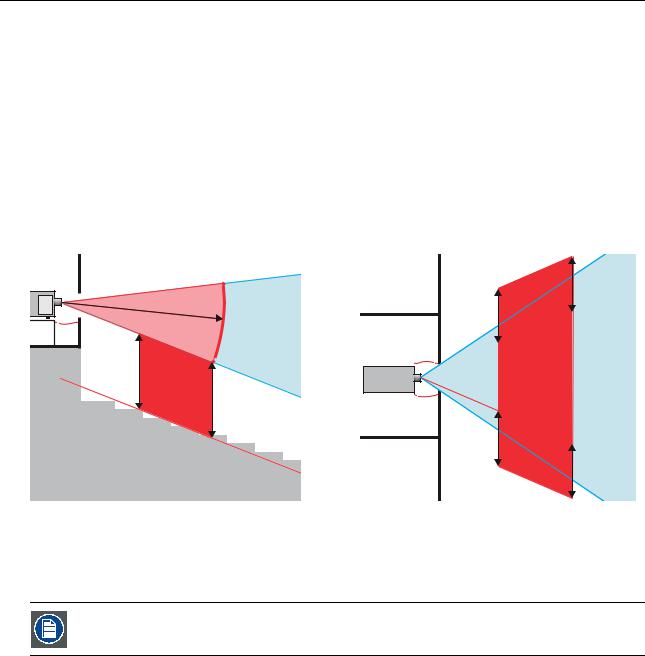
Based on national requirements, no person is allowed to enter the projected beam within the zone between the projection lens and the related hazard distance (HD). This shall be physically impossible by creating sufficient separation height or by placing barriers. The minimum separation height takes into account the surface upon which persons other than operator, performers or employees are permitted to stand.
On image 1-2 a typical setup is displayed. It must be verified if these minimum requirements are met. If required a restricted zone (RZ) in the theater must be established. This can be done by using physical barrier, like a red rope as illustrated in image 1-2.
The restricted area sticker can be replaced by a sticker with only the symbol.
8 |
|
601–0400 F90 SERIES. 10/05/2017 |
1. Safety
RESTRICTED
AREA
RESTRICTED
AREA
PR
Image 1-2
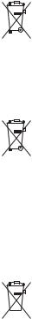
1.5Hazard Distance for fully closed projection system
HD
Hazard Distance (HD) is the distance measured from the projection lens at which the intensity or the energy per surface unit becomes lower than the applicable exposure limit on the cornea or on the skin. The light beam is considered (to be) unsafe for exposure if the distance from a person to the light source is less than the HD.
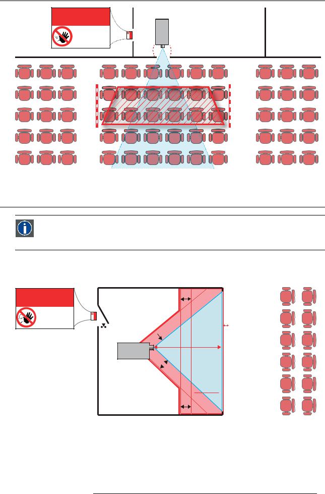
Restriction Zone RZ Based on the HD
The projector is also suitable for rear projection applications; projecting a beam onto a defuse coated projection screen. As displayed in image 1-3 two areas should be considered: the restricted enclosed projection area (RA) and the observation area (TH).
RESTRICTED
AREA
RA
RESTRICTED
AREA
sw
RZ
 sw
sw
PD
PR
sw
HD
 REFLECTION
sw
TH
HDDIFFUSE
Image 1-3
RA |
Restricted Access location (Enclosed projection area) |
PR |
Projector. |
TH |
Theater (observation area). |
RZ |
Restriction Zone |
PD |
Projection Distan |
SW |
Separation Width. Must be minimum 1 meter. |
Restriction zone (RZ) based on the HD continued.
For this type of setup 3 different HD shall be considered:
601–0400 F90 SERIES. 10/05/2017 |
9 |
1.Safety
•HD as discussed in "High Brightness precautions: Hazard Distance (HD)", page 6 , relevant for intrabeam exposure.
•HDreflection : the distance that has to be kept restrictive related to the reflected light from the rear projection screen.
•HDdiffuse : the relevant distance to be considered while observing the defuse surface of the rear projection screen.
As described in "High Brightness precautions: Hazard Distance (HD)", page 6 , it is mandatory to create a restricted zone within the beam areas closer than any NOHD. In the enclosed projection area the combination of two restricted zones are relevant: The restricted zone of the projected beam toward the screen; taking into account 1 meter Separation Width (SW) from the beam onward. Combined with the restricted zone related to the rear reflection from the screen (HDreflection); also taking into account a 1 meter lateral separation.
The HDreflection distance equals 25% of the difference between the determined HD distance and the projection distance to the rear projection screen. To determine the HD distance for the used lens and projector model see graphs in chapter "HD in function of the lens Throw Ratio (TR)", page 8 .
HDreflection = 25% (HD – PD)
The light emitted from the screen within the observation shall never exceed the RG2 exposure limit, determined at 10 cm. The HDdiffuse can be neglected if the measured light at the screen surface is below 5000 cd/m² or 15000 LUX.
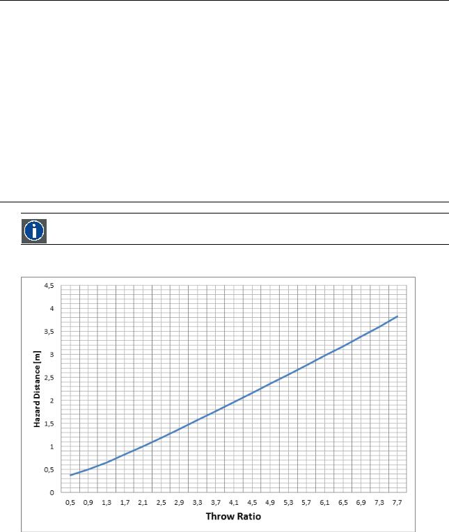
1.6HD in function of the lens Throw Ratio (TR)
TR (Throw Ratio)
The ratio of the distance to the screen (throw) to the screen width.
HD versus Throw Ratio
Image 1-4
Hazard Distance in meters versus Throw ratio of the lens for the F90 projectors
10 |
|
601–0400 F90 SERIES. 10/05/2017 |

1. Safety
Hazard Distance Thermal Acidental Exposure
Hazard Distance [m]
1,8
1,6
1,4
1,2
1
0,8
0,6
0,4
0,2
0
0,5 |
0,9 |
1,3 |
1,7 |
2,0 |
2,3 |
2,7 |
3,1 |
3,5 |
3,9 |
4,3 |
4,7 |
5,1 |
5,5 |
5,9 |
6,3 |
6,7 |
7,1 |
7,5 |
Throw Ra o
Image 1-5
Hazard Distance in meters versus Throw ratio of the lens for the F70 projectors
Graphs shows Hazard Distance in meters versus Throw ratio of the lens
1.7Safety symbols
Description of safety symbols used in product documentation or on product.
Image |
Description |
|
Refer to user manual for further information! |
|
|
|
Caution! Do not stare into beam, RG2 |
|
|
|
product. |
|
|
|
|
|
|
|
No telephone! Do not connect to telephone |
|
|
|
lines. |
|
|
|
|
For F90 series: Warning Label |
|
|
Caution! For North America: With |
|
|
|
interchangeable lens with throw ratio greater |
For North America, this projector may become RG3 when an interchangeable lens with throw ratio greater than |
This projector may become RG3 when an interchangeable lens with throw ratio greater than 3.15 is |
than 2.33, consider hazard distance and |
|
2.33 is installed. Refer to the manual for the lens list and hazard distance before operation. Such combinations of |
installed. Refer to the manual for the lens list and hazard distance before operation. Such combinations |
installation requirements for RG3 product. |
|
projector and lens are intended for professional use only, and are not intended for consumer use. |
of projector and lens are intended for professional use only, and are not intended for consumer use. |
||
Ce projecteur peut devenir un projecteur RG3 en cas d'installation d'un objectif interchangeable |
3.15 |
RG3 |
Refer User Manual. |
plus sur la liste des objectifs et la distance de sécurité avant toute utilisation. De telles combinaisons |
|||
dont le rapport de projection est supérieur à 3,15.Veuillez vous reporter au manuel pour en savoir |
|
||
entre projecteur et objectif sont conçues pour des applications professionnelles uniquement et pas |
|
|
|
pour des applications grand public. |
|
|
|
Caution! With Interchangeable lens with throw ratio greater then 3.15, consider hazard distance and installation
requirements for RG3 product. Refer User manual.
601–0400 F90 SERIES. 10/05/2017 |
|
11 |
1. Safety
Image |
|
|
Description |
||
|
|
|
|
||
For F90 series: FDA Label |
|
|
|
||
THIS PRODUCT IS IN CONFORMITY |
|
|
|
||
WITH PERFORMANCE STANDARDS |
|
|
|
||
FOR LASER PRODUCTS UNDER 21 |
|
|
|
||
CFR 1040, EXCEPT WITH RESPECT TO |
|
|
|
||
THOSE CHARACTERISTICS |
|
|
|
||
AUTHORIZED BY VARIANCE NUMBER |
|
|
|
||
|
|
2016-V-0144 EFFECTIVE |
|
|
|
|
|
|
|
|
|
|
|
MARCH 6, 2017. |
|
|
|
|
|
|
|
||
|
|
|
|
||
For F70 Series: Warning label |
|
|
Caution! For North America: With |
||
|
|
|
|
|
interchangeable lens with throw ratio greater |
For North America, this projector may become RG3 when an interchangeable lens with throw ratio |
This projector may become RG3 when an interchangeable lens with throw ratio greater than 4.7 is |
than 2.5, consider hazard distance and |
|||
for consumer use. |
for consumer use. |
|
installation requirements for RG3 product. |
||
greater than 2.5 is installed. Refer to the manual for the lens list and hazard distance before operation. |
installed. Refer to the manual for the lens list and hazard distance before operation. Such |
|
|||
Such combinations of projector and lens are intended for professional use only, and are not intended |
combinations of projector and lens are intended for professional use only, and are not intended |
|
|||
Ce projecteur peut devenir un projecteur RG3 en cas d'installation d'un objectif interchangeable |
4.7 |
RG3 |
Refer User Manual |
||
dont le rapport de projection est supérieur à 4.7.Veuillez vous reporter au manuel pour en savoir |
|
||||
plus sur la liste des objectifs et la distance de sécurité avant toute utilisation. De telles combinaisons |
|
|
Caution! With Interchangeable lens with |
||
entre projecteur et objectif sont conçues pour des applications professionnelles uniquement et pas |
|
|
|||
pour des applications grand public. |
|
|
|
||
|
|
|
|
|
throw ratio greater then 4.7, consider hazard |
|
|
|
|
|
distance and installation requirements for |
|
|
|
|
|
RG3 product. Refer User manual. |
For F70 Series: FDA Label |
|
|
|
||
THIS PRODUCT IS IN CONFORMITY WITH PERFORMANCE STANDARDS FOR LASER PRODUCTS UNDER 21 CFR 1040, EXCEPT WITH RESPECT TO THOSE CHARACTERISTICS AUTHORIZED BY VARIANCE NUMBER 2016-V-0144 EFFECTIVE MARCH 6, 2017.
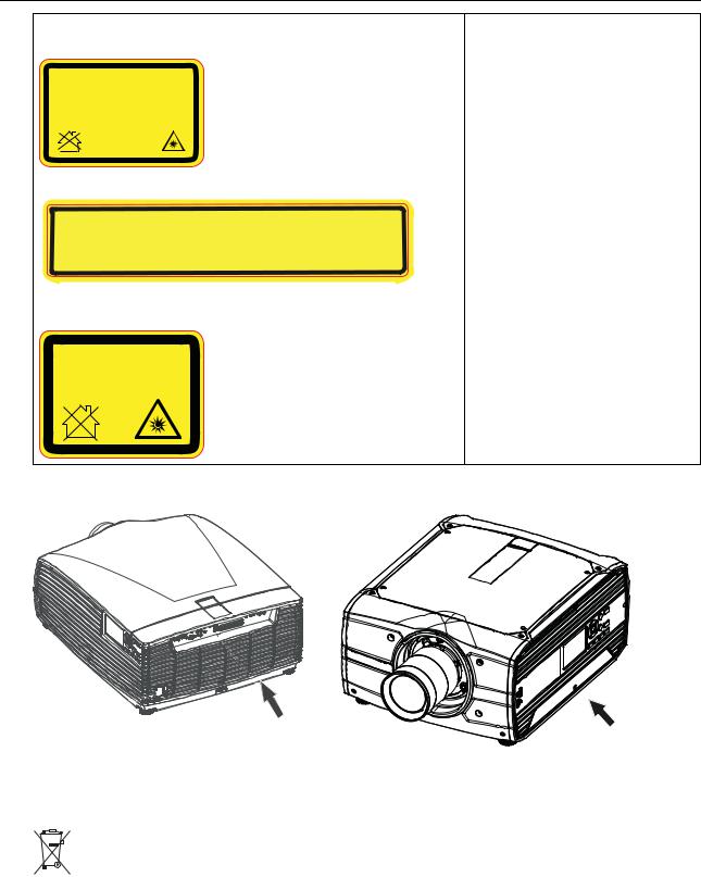
Location of Safety Label
9
8
Image 1-6
F90 Projector
Image 1-7
F70 Projector
Disposal Information
Waste Electrical and Electronic Equipment
 This symbol on the product indicates that, under the European Directive 2012/19/EU governing waste from electrical and electronic equipment, this product must not be disposed of with other municipal waste. Please dispose of your waste equipment by handing it over to a designated collection point for the recycling of waste electrical and electronic equipment. To prevent possible harm to the environment or human health from uncontrolled waste disposal, please separate these items from other types of waste and recycle them responsibly to promote the sustainable reuse of material resources.
For more information about recycling of this product, please contact your local city office or your municipal waste disposal service.
For details, please visit the Barco website at: http://www.barco.com/en/AboutBarco/weee
12 |
|
601–0400 F90 SERIES. 10/05/2017 |
1. Safety
WEEE Information
This product conforms to all requirements of the EU Directive on waste electrical and electronic equipment (WEEE). This product shall be recycled properly. It can be disassembled to facilitate proper recycling of it’s individual parts.
Consult your dealer or relevant public authority regarding drop-off points for collection of WEEE. For details, please visit the Barco website at: http://www.barco.com/en/ AboutBarco/weee.
WARNING: This product contains chemicals, including lead, known to the State of California to cause birth defects or other reproductive harm. Recycle properly, do not dispose of in ordinary waste!
Turkey RoHS compliance
 Türkiye Cumhuriyeti: AEEE Yönetmeliğine Uygundur.
[Republic of Turkey: In conformity with the WEEE Regulation]
1.8RoHS compliance
RoHS (Chinese Mainland RoHS)
RoHS Barco/ RoHS MCV “ ”
According to the “Management Methods for the Restriction of the Use of Hazardous Substances in Electrical and Electronic Products” (Also called RoHS of Chinese Mainland), the table below lists the names and contents of toxic and/or hazardous substances that Barco’s product may contain. The RoHS of Chinese Mainland is included in the MCV standard of the Ministry of Information Industry of China, in the section “Limit Requirements of toxic substances in Electronic Information Products”.
601–0400 F90 SERIES. 10/05/2017 |
|
13 |

1. Safety
|
|
|
|
|
|
|
|
|
|
Component Name |
Hazardous Substances or Elements |
|
|
|
|
|
|
||
|
|
|
|
|
|
|
|
|
|
|
|
|
|
|
|
|
|
|
|
|
(Pb) |
(Hg) |
(Cd) |
(Cr6+) |
|
(PBB) |
(PBDE) |
||
|
|
|
|
|
|
|
|
|
|
|
X |
O |
X |
O |
|
|
O |
|
O |
Printed Circuit Assemblies |
|
|
|
|
|
|
|
|
|
|
X |
O |
O |
O |
|
|
O |
|
O |
External Cables |
|
|
|
|
|
|
|
|
|
|
X |
O |
O |
O |
|
|
O |
|
O |
Internal wiring |
|
|
|
|
|
|
|
|
|
|
|
|
|
|
|
|
|
|
|
|
X |
O |
O |
O |
|
|
O |
|
O |
Lensholder |
|
|
|
|
|
|
|
|
|
|
|
|
|
|
|
|
|
|
|
|
X |
O |
O |
O |
|
|
O |
|
O |
Laser |
|
|
|
|
|
|
|
|
|
|
|
|
|
|
|
|
|
|
|
|
O |
O |
O |
O |
|
|
O |
|
O |
Chassis |
|
|
|
|
|
|
|
|
|
|
|
|
|
|
|
|
|
|
|
|
O |
O |
O |
O |
|
|
O |
|
O |
Enclosure |
|
|
|
|
|
|
|
|
|
|
X |
O |
O |
O |
|
|
O |
|
O |
Nuts, bolts, screws, washers. Fasteners |
|
|
|
|
|
|
|
|
|
|
|
|
|
|
|
|
|
|
|
|
X |
O |
O |
O |
|
|
O |
|
O |
Power Supply Unit |
|
|
|
|
|
|
|
|
|
|
|
|
|
|
|
|
|
|
|
|
O |
O |
O |
O |
|
|
O |
|
O |
Heatsinks |
|
|
|
|
|
|
|
|
|
|
|
|
|
|
|
|
|
|
|
|
X |
O |
O |
O |
|
|
O |
|
O |
Fan |
|
|
|
|
|
|
|
|
|
|
|
|
|
|
|
|
|
|
|
|
O |
O |
O |
O |
|
|
O |
|
O |
Plastic Enclosure |
|
|
|
|
|
|
|
|
|
|
O |
O |
O |
O |
|
|
O |
|
O |
Enclosure |
|
|
|
|
|
|
|
|
|
|
O |
O |
O |
O |
|
|
O |
|
O |
Batteries |
|
|
|
|
|
|
|
|
|
|
|
|
|
|
|
|
|
|
|
|
O |
O |
O |
O |
|
|
O |
|
O |
Paper Manuals |
|
|
|
|
|
|
|
|
|
|
|
|
|
|
|
|
|
|
|
|
O |
O |
O |
O |
|
|
O |
|
O |
Installation kit |
|
|
|
|
|
|
|
|
|
|
|
|
|
|
|
|
|
|
|
|
X |
O |
O |
O |
|
|
O |
|
O |
Remote control |
|
|
|
|
|
|
|
|
|
|
|
|
|
|
|
|
|
|
|
SJ/T 11364 |
|
|
|
|
|
|
|
|
|
This table is prepared in accordance with the provisions of SJ/T 11364. |
|
|
|
|
|
|
|
||
O: GB/T 26572 |
|
|
|
|
|||||
O: Indicates that this toxic or hazardous substance contained in all of the homogeneous materials for this part is below the |
|||||||||
limit requirement in GB/T 26572 |
|
|
|
|
|
|
|
|
|
X: GB/T 26572 |
|
|
|
||||||
X: Indicates that this toxic or hazardous substance contained in at least one of the homogeneous materials used forth is part |
|||||||||
is above the limit requirement in GB/T 26572. |
|
|
|
|
|
|
|
|
|
|
|
|
|
|
|
|
|
|
|
Image 1-8 |
|
|
|
|
|
|
|
|
|
14 |
|
601–0400 F90 SERIES. 10/05/2017 |

|
|
|
|
|
|
|
1. Safety |
|
|
|
|
|
|
|
|
|
|
|
|
|
|
|
|
|
( ) |
|
|
|
|
|
|
|
Component Name |
Hazardous Substances or Elements |
|
|
|
||
|
|
|
|
|
|
|
|
|
|
(Pb) |
(Hg) |
(Cd) |
(Cr6+) |
(PBB) |
(PBDE) |
|
|
X |
O |
X |
O |
O |
O |
|
Printed Circuit Assemblies |
|
|
|
|
|
|
|
( ) |
X |
O |
O |
O |
O |
O |
|
External Cables |
|
|
|
|
|
|
|
|
X |
O |
O |
O |
O |
O |
|
Internal wiring |
|
|
|
|
|
|
|
|
X |
O |
O |
O |
O |
O |
|
Lensholder |
|
|
|
|
|
|
|
|
X |
O |
O |
O |
O |
O |
|
Laser |
|
|
|
|
|
|
|
|
O |
O |
O |
O |
O |
O |
|
Chassis |
|
|
|
|
|
|
|
|
O |
O |
O |
O |
O |
O |
|
Enclosure |
|
|
|
|
|
|
|
, ( ), ( ), , |
X |
O |
O |
O |
O |
O |
|
Nuts, bolts, screws, washers, Fasteners |
|
|
|
|
|
|
|
|
X |
O |
O |
O |
O |
O |
|
Power Supply Unit |
|
|
|
|
|
|
|
( ) |
O |
O |
O |
O |
O |
O |
|
Heatsinks |
|
|
|
|
|
|
|
|
X |
O |
O |
O |
O |
O |
|
Fan |
|
|
|
|
|
|
|
|
O |
O |
O |
O |
O |
O |
|
Plastic Enclosure |
|
|
|
|
|
|
|
|
O |
O |
O |
O |
O |
O |
|
Enclosure |
|
|
|
|
|
|
|
( ) |
O |
O |
O |
O |
O |
O |
|
Batteries |
|
|
|
|
|
|
|
|
O |
O |
O |
O |
O |
O |
|
Paper Manuals |
|
|
|
|
|
|
|
|
O |
O |
O |
O |
O |
O |
|
Installation kit |
|
|
|
|
|
|
|
|
|
|
|
|
|
|
|
|
X |
O |
O |
O |
O |
O |
|
Remote control |
|
|
|
|
|
|
|
SJ/T 11364 |
|
|
|
|
|
|
This table is prepared in accordance with the provisions of SJ/T 11364.
O: GB/T 26572 .
O: Indicates that this toxic or hazardous substance contained in all of the homogeneous materials for this part is below the limit requirement in GB/T 26572.
X: GB/T 26572 .
X: Indicates that this toxic or hazardous substance contained in at least one of the homogeneous materials used for this part is above the limit requirement in GB/T 26572.
EIPEFUP Barco EFUP
601–0400 F90 SERIES. 10/05/2017 |
|
15 |

1. Safety
All Electronic Information Products (EIP) that are sold within Chinese Mainland must comply with the “Marking for the restriction of the use of hazardous substances in electrical and electronic product” of Chinese Mainland, marked with the Environmental Friendly Use Period (EFUP) logo. The number inside the EFUP logo that Barco uses (please refer to the photo) is based on the “General guidelines of environment-friendly use period of electronic information products” of Chinese Mainland.
 10
10
1.9Contact adresses
For Taiwan:
AWIND Inc., 33F., No. 16. Xinzhan Rd., Banqiao Dist.,, New Taipei City 220, Taiwan
Tel: +886-2-7715-0099, Fax: +886-2-7715-0097
E-mail: sales@awindinc.com
1.10 Product Info
Product info
Image 1-9
product name :
projector
model : GP6 / GP7
1.11 Statement
EN55032/CISPR32 Class A MME (MultiMedia Equipment)
Warning : This equipment is compliant with Class A of CISPR 32. In a residential environment this equipment may cause radio interference.
Class A ITE (Information Technology Equipment)
Warning : This is a class A product. In a domestic environment this product may cause radio interference in which case the user may be required to take adequate measures.
16 |
|
601–0400 F90 SERIES. 10/05/2017 |
2. Getting to know the projector
2. GETTING TO KNOW THE PROJECTOR
Overview
•Main components
•Service and maintenance
•LED status light
•Power on / Standby button backlight indications
•LCD panel
•Local keypad
•Remote control, Battery installation
•Remote control, protocol setup
•Functionality overview
•Projector Address
•Connector panel
•Color Wheels
•Optional accessories
2.1Main components
Naming conventions
T
B
L

 R
R
|
F |
Image 2-1 |
|
L |
Left |
T |
Top |
B |
Back |
R |
Right |
F |
Front |
601–0400 F90 SERIES. 10/05/2017 |
|
17 |

2. Getting to know the projector
Projector Front
1 |
2 |
3 |
2 |
1 |
||
|
|
1 |
Image 2-2
1LED status light
2Adjustable feet
3Projector lens
4Lens holder
5IR Receiver: for remote control communication
6LCD panel
7Keypad
8Connector panel
9Front USB and triggerboard
5 |
4 |
5 |
8 |
7 |
6 |
2 |
9 |
2.2Service and maintenance
General
The F90 does not have any user-serviceable parts.
All service tasks must only be carried out by the manufacturer, or a Barco authorized service personnel or Barco technicians.
The projector color wheel is a designed consumable that can be replaced by users in the field. See "Change the color wheel ", page 24 for more information.
2.3LED status light
About
The F90 status indicator is located on the top side of the projector, near the IR receiver (ref. 1, image 2-2).
During normal operation the LED is unlit. In the event of a critical error or high temperature, the LED will display red.
In event of a critical error, the projector cannot be restarted until the projector is disconnected from the power supply and then reconnected again. If the reason for the error persists, the projector will again go to critical error status.
If the root cause of the error is high temperature, the projector will restart when it has cooled down, and temperatures are back within the normal operating limitations.
2.4Power on / Standby button backlight indications
Indicator
In addition to the LED indicator, the projector also displays status indications in the backlight of the Power / Standby button.
The table below shows the details regarding this indications.
Operating Status |
Indication Color / Behavior |
|
|
On (active) |
Blue |
|
|
18 |
|
601–0400 F90 SERIES. 10/05/2017 |
 Loading...