


a`pJOMM
rлЙкЫл=dмбЗЙ
•
•
Manual #: 26-0604010-00 Revision: 00

a`pJOMM==√==rлЙкЫл=dмбЗЙ
`зйукбЦЬн
© Barco. May 30, 2008
All rights reserved. No part of this document may be copied, reproduced or translated. It shall not otherwise be recorded, transmitted or stored in a retrieval system without the prior written consent of Barco.
kзнбЕЙ
Barco provides this manual “as is” without warranty of any kind, either expressed or implied, including but not limited to the implied warranties or merchantability and fitness for a particular purpose. Barco may make improvements and/or changes to the product(s) and/ or the program(s) described in this publication at any time without notice.
This publication could contain technical inaccuracies or typographical errors. Changes are periodically made to the information in this publication; these changes are incorporated in new editions of this publication.
cЙЗЙк~д=`зггмебЕ~нбзел=`зггбллбзе=Ec``F=pн~нЙгЙен
This equipment has been tested and found to comply with the limits for a class A digital device, pursuant to Part 15 of the FCC rules. These limits are designed to provide reasonable protection against harmful interference when the equipment is operated in a commercial environment. This equipment generates, uses, and can radiate radio frequency energy and, if not installed and used in accordance with the instruction manual, may cause harmful interference to radio communications. Operation of this equipment in a residential area may cause harmful interference, in which case the user will be responsible for correcting any interference.
dм~к~енЙЙ=~еЗ=`згйЙел~нбзе
Barco provides a guarantee relating to perfect manufacturing as part of the legally stipulated terms of guarantee. On receipt, the purchaser must immediately inspect all delivered goods for damage incurred during transport, as well as for material and manufacturing faults. Barco must be informed immediately in writing of any complaints.
The period of guarantee begins on the date of transfer of risks, in the case of special systems and software on the date of commissioning, at latest 30 days after the transfer of risks. In the event of justified notice of compliant, Barco can repair the fault or provide a replacement at its own discretion within an appropriate period. If this measure proves to be impossible or unsuccessful, the purchaser can demand a reduction in the purchase price or cancellation of the contract. All other claims, in particular those relating to compensation for direct or indirect damage, and also damage attributed to the operation of software as well as to other services provided by Barco, being a component of the system or independent service, will be deemed invalid provided the damage is not proven to be attributed to the absence of properties guaranteed in writing or due to the intent or gross negligence or part of Barco.
If the purchaser or a third party carries out modifications or repairs on goods delivered by Barco, or if the goods are handled incorrectly, in particular if the systems are commissioned operated incorrectly or if, after the transfer of risks, the goods are subject to influences not
2 |
|
DCS-200 • User’s Guide |
|

agreed upon in the contract, all guarantee claims of the purchaser will be rendered invalid. Not included in the guarantee coverage are system failures which are attributed to programs or special electronic circuitry provided by the purchaser, e.g. interfaces. Normal wear as well as normal maintenance are not subject to the guarantee provided by Barco either.
The environmental conditions as well as the servicing and maintenance regulations specified in this manual must be complied with by the customer.
qê~ÇÉã~êâë
Brand and product names mentioned in this manual may be trademarks, registered trademarks or copyrights of their respective holders. All brand and product names mentioned in this manual serve as comments or examples and are not to be understood as advertising for the products or their manufactures.
`згй~еу=^ЗЗкЙлл
Barco Media and Entertainment
11101 Trade Center Drive
Rancho Cordova, California 95670
USA
•
•
•
•
Phone: (916) 859-2500 Toll Free: (888) 414-7226 Fax: (916) 859-2515 Website: www.barco.com
Barco N.V.
Noordlaan 5
8520 Kuurne
BELGIUM
•
•
•
Phone: +32 56.36.82.11 Fax: +32 56.35.16.51 Website: www.barco.com
Technical Support
•Tech Line: (866) 374-7878 — 24 hours per day, 7 days per week
DCS-200 • User’s Guide |
|
3 |
|

léÉê~íçêë=p~ÑÉíó=pìãã~êó
The general safety information in this summary is for operating personnel.
aз=kзн=oЙгзоЙ=`зоЙкл=зк=m~еЙдл
There are no user-serviceable parts within the unit. Removal of the top cover will expose dangerous voltages. To avoid personal injury, do not remove the top cover. Do not operate the unit without the cover installed.
mзпЙк=pзмкЕЙ
This product is intended to operate from a power source that will not apply more than 230 volts rms between the supply conductors or between both supply conductor and ground. A protective ground connection by way of grounding conductor in the power cord is essential for safe operation.
dкзмеЗбеЦ=нЬЙ=mкзЗмЕн
This product is grounded through the grounding conductor of the power cord. To avoid electrical shock, plug the power cord into a properly wired receptacle before connecting to the product input or output terminals. A protective-ground connection by way of the grounding conductor in the power cord is essential for safe operation.
rлЙ=нЬЙ=mкзйЙк=mзпЙк=`зкЗ
Use only the power cord and connector specified for your product. Use only a power cord that is in good condition. Refer cord and connector changes to qualified service personnel.
rлЙ=нЬЙ=mкзйЙк=cмлЙ
To avoid fire hazard, use only the fuse having identical type, voltage rating, and current rating characteristics. Refer fuse replacement to qualified service personnel.
aз=kзн=lйЙк~нЙ=бе=bсйдзлбоЙ=^нгзлйЬЙкЙл
To avoid explosion, do not operate this product in an explosive atmosphere.
4 |
|
DCS-200 • User’s Guide |
|

bимбйгЙен=j~квбеЦ=~еЗ=p~СЙну=qЙкгл=
t^okfkd
Highlights an operating procedure, practice, condition, statement, etc., which, if not strictly observed, could result in injury to or death of personnel.
Note |
Highlights an essential operating procedure, condition or |
|
statement. |
|
|
`^rqflk
The exclamation point within an equilateral triangle is intended to alert the user to the presence of important operating and maintenance (servicing) instructions in the literature accompanying the appliance.
^sboqfppbjbkq>
Le point d´exclamation dans un triangle equilatéral signale à alerter l´utilisateur qu´il y a des instructions d´operation et d´entretien tres importantes dans la litérature qui accompagne l´appareil.
slopf`eq
Ein Ausrufungszeichen innerhalb eines gleichwinkeligen Dreiecks dient dazu, den Benutzer auf wichtige Bedienungs-und Wartungsanweisungen in der Dem Great beiliegenden Literatur aufmerksam zu machen.
DCS-200 • User’s Guide |
|
5 |
|

`Ь~еЦЙ=eблнзку
The table below lists the changes to the DCS-200 User’s Guide.
Table 0-1. Change History
Rev |
Date |
ECP # |
Description |
Approved By |
00 |
May 30, 2008 |
558656 |
DCS-200 User’s Guide |
R. Pellicano |
|
|
|
|
|
6 |
|
DCS-200 • User’s Guide |
|

q~ДдЙ=зС=`зенЙенл
`Ü~éíÉê=N |
fенкзЗмЕнбзе =K=K=K=K=K=K=K=K=K=K=K=K=K=K=K=K=K=K=K=K=K=K=K=K=K=K=K=K=K=K=K=K=K=K=K=K=K=K=K=K=K=NP |
|
|
In This Chapter . . . . . . . . . . . . . . . . . . . . . . . . . . . . . . . . . . . . . . . . . . . . . . . . |
13 |
|
Chapter Structure . . . . . . . . . . . . . . . . . . . . . . . . . . . . . . . . . . . . . . . . . . . . . . |
13 |
|
How to Use This Guide. . . . . . . . . . . . . . . . . . . . . . . . . . . . . . . . . . . . . . . . . . |
14 |
|
Navigating . . . . . . . . . . . . . . . . . . . . . . . . . . . . . . . . . . . . . . . . . . . . . . |
14 |
|
Table of Contents and Index . . . . . . . . . . . . . . . . . . . . . . . . . . . . . . . . |
14 |
|
Conventions . . . . . . . . . . . . . . . . . . . . . . . . . . . . . . . . . . . . . . . . . . . . . . . . . . |
14 |
|
About the DCS-200 . . . . . . . . . . . . . . . . . . . . . . . . . . . . . . . . . . . . . . . . . . . . |
15 |
|
Overview . . . . . . . . . . . . . . . . . . . . . . . . . . . . . . . . . . . . . . . . . . . . . . . |
15 |
|
Features. . . . . . . . . . . . . . . . . . . . . . . . . . . . . . . . . . . . . . . . . . . . . . . . |
15 |
|
A Word About HDCP . . . . . . . . . . . . . . . . . . . . . . . . . . . . . . . . . . . . . . |
17 |
|
Connectivity Diagram . . . . . . . . . . . . . . . . . . . . . . . . . . . . . . . . . . . . . . . . . . . |
18 |
|
Application Questions. . . . . . . . . . . . . . . . . . . . . . . . . . . . . . . . . . . . . . . . . . . |
18 |
`Ü~éíÉê=O |
e~кЗп~кЙ=lкбЙен~нбзе =K=K=K=K=K=K=K=K=K=K=K=K=K=K=K=K=K=K=K=K=K=K=K=K=K=K=K=K=K=K=K=K=NV |
|
|
In This Chapter . . . . . . . . . . . . . . . . . . . . . . . . . . . . . . . . . . . . . . . . . . . . . . . . |
19 |
|
DCS-200 Front Panel . . . . . . . . . . . . . . . . . . . . . . . . . . . . . . . . . . . . . . . . . . . |
20 |
|
Display Section . . . . . . . . . . . . . . . . . . . . . . . . . . . . . . . . . . . . . . . . . . |
21 |
|
Inputs Section . . . . . . . . . . . . . . . . . . . . . . . . . . . . . . . . . . . . . . . . . . . |
22 |
|
Effects Section. . . . . . . . . . . . . . . . . . . . . . . . . . . . . . . . . . . . . . . . . . . |
23 |
|
Take . . . . . . . . . . . . . . . . . . . . . . . . . . . . . . . . . . . . . . . . . . . . . . . . . . |
24 |
|
DCS-200 Rear Panel . . . . . . . . . . . . . . . . . . . . . . . . . . . . . . . . . . . . . . . . . . . |
25 |
`Ü~éíÉê=P |
fåëí~ää~íáçå =K=K=K=K=K=K=K=K=K=K=K=K=K=K=K=K=K=K=K=K=K=K=K=K=K=K=K=K=K=K=K=K=K=K=K=K=K=K=K=K=K=K=OT |
|
|
In This Chapter . . . . . . . . . . . . . . . . . . . . . . . . . . . . . . . . . . . . . . . . . . . . . . . . |
27 |
|
Safety Precautions . . . . . . . . . . . . . . . . . . . . . . . . . . . . . . . . . . . . . . . . . . . . . |
28 |
|
Unpacking and Inspection . . . . . . . . . . . . . . . . . . . . . . . . . . . . . . . . . . . . . . . |
28 |
|
Site Preparation . . . . . . . . . . . . . . . . . . . . . . . . . . . . . . . . . . . . . . . . . . . . . . . |
28 |
|
Cable and Adapter Information. . . . . . . . . . . . . . . . . . . . . . . . . . . . . . . . . . . . |
28 |
|
Rack-Mount Installation . . . . . . . . . . . . . . . . . . . . . . . . . . . . . . . . . . . . . . . . . |
29 |
|
Power Installation . . . . . . . . . . . . . . . . . . . . . . . . . . . . . . . . . . . . . . . . . . . . . . |
29 |
|
Power Cord/Line Voltage Selection . . . . . . . . . . . . . . . . . . . . . . . . . . . |
30 |
|
Signal Installation . . . . . . . . . . . . . . . . . . . . . . . . . . . . . . . . . . . . . . . . . . . . . . |
31 |
|
Format Connection Table . . . . . . . . . . . . . . . . . . . . . . . . . . . . . . . . . . . . . . . . |
32 |
`Ü~éíÉê=Q |
léÉê~íáçåK=K=K=K=K=K=K=K=K=K=K=K=K=K=K=K=K=K=K=K=K=K=K=K=K=K=K=K=K=K=K=K=K=K=K=K=K=K=K=K=K=K=K=K=PP |
|
|
In This Chapter . . . . . . . . . . . . . . . . . . . . . . . . . . . . . . . . . . . . . . . . . . . . . . . . |
33 |
|
Control Overview . . . . . . . . . . . . . . . . . . . . . . . . . . . . . . . . . . . . . . . . . . . . . . |
34 |
|
Power-Up Initialization . . . . . . . . . . . . . . . . . . . . . . . . . . . . . . . . . . . . . . . . . . |
34 |
|
Button States . . . . . . . . . . . . . . . . . . . . . . . . . . . . . . . . . . . . . . . . . . . . . . . . . |
35 |
DCS-200 • User’s Guide |
|
7 |
|
Table of Contents
Quick Setup and Operations . . . . . . . . . . . . . . . . . . . . . . . . . . . . . . . . . . . . . 36
Menu Tree . . . . . . . . . . . . . . . . . . . . . . . . . . . . . . . . . . . . . . . . . . . . . . . . . . . 38
Using the Menu System . . . . . . . . . . . . . . . . . . . . . . . . . . . . . . . . . . . . . . . . . 39
Quick Function Reference . . . . . . . . . . . . . . . . . . . . . . . . . . . . . . . . . . . . . . . 41
Status Menu . . . . . . . . . . . . . . . . . . . . . . . . . . . . . . . . . . . . . . . . . . . . . . . . . . 44
Using the Setup Menu . . . . . . . . . . . . . . . . . . . . . . . . . . . . . . . . . . . . . . . . . . 46
Trans Time. . . . . . . . . . . . . . . . . . . . . . . . . . . . . . . . . . . . . . . . . . . . . . 47
Output Menu . . . . . . . . . . . . . . . . . . . . . . . . . . . . . . . . . . . . . . . . . . . . 47
Output Format . . . . . . . . . . . . . . . . . . . . . . . . . . . . . . . . . . . . 48
Test Pattern. . . . . . . . . . . . . . . . . . . . . . . . . . . . . . . . . . . . . . 48
Sync Setup . . . . . . . . . . . . . . . . . . . . . . . . . . . . . . . . . . . . . . 49
Gamma . . . . . . . . . . . . . . . . . . . . . . . . . . . . . . . . . . . . . . . . . 49
Save Output Config . . . . . . . . . . . . . . . . . . . . . . . . . . . . . . . . 49
Preview Menu . . . . . . . . . . . . . . . . . . . . . . . . . . . . . . . . . . . . . . . . . . . 50
Output Src . . . . . . . . . . . . . . . . . . . . . . . . . . . . . . . . . . . . . . . 51
Output Format (Preview) . . . . . . . . . . . . . . . . . . . . . . . . . . . . 51
Test Patterns (Preview). . . . . . . . . . . . . . . . . . . . . . . . . . . . . 52
Preview Sync. . . . . . . . . . . . . . . . . . . . . . . . . . . . . . . . . . . . . 52
Save (Preview) . . . . . . . . . . . . . . . . . . . . . . . . . . . . . . . . . . . 53
Input Menu. . . . . . . . . . . . . . . . . . . . . . . . . . . . . . . . . . . . . . . . . . . . . . 53
Input Format . . . . . . . . . . . . . . . . . . . . . . . . . . . . . . . . . . . . . 55
Adjust On. . . . . . . . . . . . . . . . . . . . . . . . . . . . . . . . . . . . . . . . 55
Type . . . . . . . . . . . . . . . . . . . . . . . . . . . . . . . . . . . . . . . . . . . 56
Colorspace . . . . . . . . . . . . . . . . . . . . . . . . . . . . . . . . . . . . . . 56
Background . . . . . . . . . . . . . . . . . . . . . . . . . . . . . . . . . . . . . . 57
Timing Adjust. . . . . . . . . . . . . . . . . . . . . . . . . . . . . . . . . . . . . 57
Image Adjust . . . . . . . . . . . . . . . . . . . . . . . . . . . . . . . . . . . . . 60
Contrast. . . . . . . . . . . . . . . . . . . . . . . . . . . . . . . . . . . . . . . . . 61
Brightness . . . . . . . . . . . . . . . . . . . . . . . . . . . . . . . . . . . . . . . 61
Color Balance . . . . . . . . . . . . . . . . . . . . . . . . . . . . . . . . . . . . 62
Processing. . . . . . . . . . . . . . . . . . . . . . . . . . . . . . . . . . . . . . . 63
About Input Configuration Files . . . . . . . . . . . . . . . . . . . . . . . 63
Reset Config . . . . . . . . . . . . . . . . . . . . . . . . . . . . . . . . . . . . . 64
Save Config. . . . . . . . . . . . . . . . . . . . . . . . . . . . . . . . . . . . . . 64
Delete Config. . . . . . . . . . . . . . . . . . . . . . . . . . . . . . . . . . . . . 65
Recall Config . . . . . . . . . . . . . . . . . . . . . . . . . . . . . . . . . . . . . 66
Key Setup Menu . . . . . . . . . . . . . . . . . . . . . . . . . . . . . . . . . . . . . . . . . 67
LOGO Setup Menu . . . . . . . . . . . . . . . . . . . . . . . . . . . . . . . . . . . . . . . 69
User Preference. . . . . . . . . . . . . . . . . . . . . . . . . . . . . . . . . . . . . . . . . . 70
In Auto Acquire . . . . . . . . . . . . . . . . . . . . . . . . . . . . . . . . . . . 70
Auto Input Config. . . . . . . . . . . . . . . . . . . . . . . . . . . . . . . . . . 71
Auto Input Save. . . . . . . . . . . . . . . . . . . . . . . . . . . . . . . . . . . 72
Auto Take . . . . . . . . . . . . . . . . . . . . . . . . . . . . . . . . . . . . . . . 72
Black Auto Take . . . . . . . . . . . . . . . . . . . . . . . . . . . . . . . . . . 72
Key Auto Take. . . . . . . . . . . . . . . . . . . . . . . . . . . . . . . . . . . . 72
Menu Context . . . . . . . . . . . . . . . . . . . . . . . . . . . . . . . . . . . . 72
System Menu. . . . . . . . . . . . . . . . . . . . . . . . . . . . . . . . . . . . . . . . . . . . 73
VFD Brightness . . . . . . . . . . . . . . . . . . . . . . . . . . . . . . . . . . . 73
Ethernet. . . . . . . . . . . . . . . . . . . . . . . . . . . . . . . . . . . . . . . . . 74
Serial Setup. . . . . . . . . . . . . . . . . . . . . . . . . . . . . . . . . . . . . . 76
EDID Setup . . . . . . . . . . . . . . . . . . . . . . . . . . . . . . . . . . . . . . 77
DVI Cable Equalization . . . . . . . . . . . . . . . . . . . . . . . . . . . . . 79
8 |
|
DCS-200 • User’s Guide |
|
Table of Contents
|
File Association Menu . . . . . . . . . . . . . . . . . . . . . . . . . . . . . |
. 79 |
|
Temperature . . . . . . . . . . . . . . . . . . . . . . . . . . . . . . . . . . . . |
. 80 |
|
Diagnostics . . . . . . . . . . . . . . . . . . . . . . . . . . . . . . . . . . . . . . |
81 |
|
Save System State . . . . . . . . . . . . . . . . . . . . . . . . . . . . . . . . |
81 |
|
Tech Support . . . . . . . . . . . . . . . . . . . . . . . . . . . . . . . . . . . . . . . . . . . . |
82 |
|
Factory Reset . . . . . . . . . . . . . . . . . . . . . . . . . . . . . . . . . . . . . . . . . . . |
82 |
|
Using Inputs . . . . . . . . . . . . . . . . . . . . . . . . . . . . . . . . . . . . . . . . . . . . . . . . . . |
84 |
|
Input Selection Rules. . . . . . . . . . . . . . . . . . . . . . . . . . . . . . . . . . . . . . |
84 |
|
Flip-flop Mode . . . . . . . . . . . . . . . . . . . . . . . . . . . . . . . . . . . . . . . . . . . |
85 |
|
Understanding Auto Acquire . . . . . . . . . . . . . . . . . . . . . . . . . . . . . . . . |
86 |
|
Using HDCP . . . . . . . . . . . . . . . . . . . . . . . . . . . . . . . . . . . . . . . . . . . . |
86 |
|
Using the LOGO . . . . . . . . . . . . . . . . . . . . . . . . . . . . . . . . . . . . . . . . . . . . . . . |
88 |
|
Saving a Logo . . . . . . . . . . . . . . . . . . . . . . . . . . . . . . . . . . . . . . . . . . . |
89 |
|
Transitioning to a Logo . . . . . . . . . . . . . . . . . . . . . . . . . . . . . . . . . . . . |
90 |
|
Deleting a Logo . . . . . . . . . . . . . . . . . . . . . . . . . . . . . . . . . . . . . . . . . . |
90 |
|
Using Freeze . . . . . . . . . . . . . . . . . . . . . . . . . . . . . . . . . . . . . . . . . . . . . . . . . |
92 |
|
Using Black. . . . . . . . . . . . . . . . . . . . . . . . . . . . . . . . . . . . . . . . . . . . . . . . . . . |
93 |
|
Black Auto Take Off. . . . . . . . . . . . . . . . . . . . . . . . . . . . . . . . . . . . . . . |
93 |
|
Black Auto Take On. . . . . . . . . . . . . . . . . . . . . . . . . . . . . . . . . . . . . . . |
94 |
|
Using Keys . . . . . . . . . . . . . . . . . . . . . . . . . . . . . . . . . . . . . . . . . . . . . . . . . . . |
95 |
|
Introduction to Keying . . . . . . . . . . . . . . . . . . . . . . . . . . . . . . . . . . . . . |
95 |
|
Performing a Key . . . . . . . . . . . . . . . . . . . . . . . . . . . . . . . . . . . . . . . . . |
96 |
|
Key Auto Take Off . . . . . . . . . . . . . . . . . . . . . . . . . . . . . . . . . |
96 |
|
Key Auto Take On . . . . . . . . . . . . . . . . . . . . . . . . . . . . . . . . . |
97 |
|
Key Transition Combinations. . . . . . . . . . . . . . . . . . . . . . . . . . . . . . . . |
97 |
|
Mix Key Up . . . . . . . . . . . . . . . . . . . . . . . . . . . . . . . . . . . . . . |
98 |
|
Mix Key Down . . . . . . . . . . . . . . . . . . . . . . . . . . . . . . . . . . . . |
98 |
|
Mix Source plus Key Up . . . . . . . . . . . . . . . . . . . . . . . . . . . . |
98 |
|
Mix Source plus Key Down . . . . . . . . . . . . . . . . . . . . . . . . . . |
99 |
|
Source Transition Under Key . . . . . . . . . . . . . . . . . . . . . . . . |
99 |
|
Fade to Black from Source plus Key . . . . . . . . . . . . . . . . . . |
100 |
|
Fade up from Black to Source plus Key . . . . . . . . . . . . . . . |
100 |
|
Understanding Front-Panel Lockout. . . . . . . . . . . . . . . . . . . . . . . . . . . . . . . |
101 |
|
Full Lockout Mode . . . . . . . . . . . . . . . . . . . . . . . . . . . . . . . . . . . . . . . |
101 |
|
Executive Lockout Mode . . . . . . . . . . . . . . . . . . . . . . . . . . . . . . . . . . |
101 |
`Ü~éíÉê=R |
drf=lйЙк~нбзел =K=K=K=K=K=K=K=K=K=K=K=K=K=K=K=K=K=K=K=K=K=K=K=K=K=K=K=K=K=K=K=K=K=K=K=K=KNMP |
|
|
In This Chapter . . . . . . . . . . . . . . . . . . . . . . . . . . . . . . . . . . . . . . . . . . . . . . . |
103 |
|
GUI Connection and Launch . . . . . . . . . . . . . . . . . . . . . . . . . . . . . . . . . . . . |
104 |
|
GUI Operations. . . . . . . . . . . . . . . . . . . . . . . . . . . . . . . . . . . . . . . . . . . . . . . |
106 |
`Ü~éíÉê=S |
réÖê~ÇáåÖ=pçÑíï~êÉK=K=K=K=K=K=K=K=K=K=K=K=K=K=K=K=K=K=K=K=K=K=K=K=K=K=K=K=K=K=K=K=KNMT |
|
|
In This Chapter . . . . . . . . . . . . . . . . . . . . . . . . . . . . . . . . . . . . . . . . . . . . . . . |
107 |
|
Software Upgrade Overview. . . . . . . . . . . . . . . . . . . . . . . . . . . . . . . . . . . . . |
108 |
|
Hardware Requirements. . . . . . . . . . . . . . . . . . . . . . . . . . . . . . . . . . . . . . . . |
108 |
|
Software Requirements . . . . . . . . . . . . . . . . . . . . . . . . . . . . . . . . . . . . . . . . |
108 |
|
Downloading Software . . . . . . . . . . . . . . . . . . . . . . . . . . . . . . . . . . . . . . . . . |
109 |
|
Via FTP Site. . . . . . . . . . . . . . . . . . . . . . . . . . . . . . . . . . . . . . . . . . . . |
109 |
|
Via Web Site . . . . . . . . . . . . . . . . . . . . . . . . . . . . . . . . . . . . . . . . . . . |
109 |
|
Ethernet Upgrade Method . . . . . . . . . . . . . . . . . . . . . . . . . . . . . . . . . . . . . . |
110 |
DCS-200 • User’s Guide |
|
9 |
|
Table of Contents
Troubleshooting Ethernet Communication . . . . . . . . . . . . . . . . . . . . 113
^ййЙеЗбс=^= pйЙЕбСбЕ~нбзелK=K=K=K=K=K=K=K=K=K=K=K=K=K=K=K=K=K=K=K=K=K=K=K=K=K=K=K=K=K=K=K=K=K=K=K=K=K=KNNR
In This Appendix. . . . . . . . . . . . . . . . . . . . . . . . . . . . . . . . . . . . . . . . . . . . . . 115
Input Specifications . . . . . . . . . . . . . . . . . . . . . . . . . . . . . . . . . . . . . . . . . . . 116
Output Specifications . . . . . . . . . . . . . . . . . . . . . . . . . . . . . . . . . . . . . . . . . . 116
Physical and Electrical Specifications . . . . . . . . . . . . . . . . . . . . . . . . . . . . . 117
Communications Specifications . . . . . . . . . . . . . . . . . . . . . . . . . . . . . . . . . . 117
Agency Specifications . . . . . . . . . . . . . . . . . . . . . . . . . . . . . . . . . . . . . . . . . 117
Pinouts . . . . . . . . . . . . . . . . . . . . . . . . . . . . . . . . . . . . . . . . . . . . . . . . . . . . . 118
Analog 15-pin D Connector . . . . . . . . . . . . . . . . . . . . . . . . . . . . . . . . 118
DVI-I Connector . . . . . . . . . . . . . . . . . . . . . . . . . . . . . . . . . . . . . . . . . 119
Ethernet Connector . . . . . . . . . . . . . . . . . . . . . . . . . . . . . . . . . . . . . . 120
Serial Connector . . . . . . . . . . . . . . . . . . . . . . . . . . . . . . . . . . . . . . . . 121
Format Table . . . . . . . . . . . . . . . . . . . . . . . . . . . . . . . . . . . . . . . . . . . . . . . . 122
^ййЙеЗбс=_= oЙгзнЙ=`зенкзд=K=K=K=K=K=K=K=K=K=K=K=K=K=K=K=K=K=K=K=K=K=K=K=K=K=K=K=K=K=K=K=K=K=K=K=K=KNOT
In This Appendix. . . . . . . . . . . . . . . . . . . . . . . . . . . . . . . . . . . . . . . . . . . . . . 127
Communicating with DCS-200 . . . . . . . . . . . . . . . . . . . . . . . . . . . . . . . . . . . 127
Command Protocol. . . . . . . . . . . . . . . . . . . . . . . . . . . . . . . . . . . . . . . . . . . . 128
Command Responses . . . . . . . . . . . . . . . . . . . . . . . . . . . . . . . . . . . . 128
Query Options . . . . . . . . . . . . . . . . . . . . . . . . . . . . . . . . . . . . . . . . . . 128
IBRT . . . . . . . . . . . . . . . . . . . . . . . . . . . . . . . . . . . . . . . . . . 128
Error Codes . . . . . . . . . . . . . . . . . . . . . . . . . . . . . . . . . . . . . . . . . . . . . . . . . 130
Error Codes: General Failures . . . . . . . . . . . . . . . . . . . . . . . . . . . . . 130
Error Codes: No Error. . . . . . . . . . . . . . . . . . . . . . . . . . . . . . . . . . . . 130
DCS-200 Command List. . . . . . . . . . . . . . . . . . . . . . . . . . . . . . . . . . . . . . . . 131
Remote Commands . . . . . . . . . . . . . . . . . . . . . . . . . . . . . . . . . . . . . . . . . . . 134
Ethernet Commands . . . . . . . . . . . . . . . . . . . . . . . . . . . . . . . . . . . . . 134
DHCP . . . . . . . . . . . . . . . . . . . . . . . . . . . . . . . . . . . . . . . . . 134
EMAC . . . . . . . . . . . . . . . . . . . . . . . . . . . . . . . . . . . . . . . . . 134
GATEWAY . . . . . . . . . . . . . . . . . . . . . . . . . . . . . . . . . . . . . 135
IP . . . . . . . . . . . . . . . . . . . . . . . . . . . . . . . . . . . . . . . . . . . . . 135
SUBNET . . . . . . . . . . . . . . . . . . . . . . . . . . . . . . . . . . . . . . . 135
Input Commands . . . . . . . . . . . . . . . . . . . . . . . . . . . . . . . . . . . . . . . . 135
ACQ. . . . . . . . . . . . . . . . . . . . . . . . . . . . . . . . . . . . . . . . . . . 135
AUTOACQ. . . . . . . . . . . . . . . . . . . . . . . . . . . . . . . . . . . . . . 135
BACKGND. . . . . . . . . . . . . . . . . . . . . . . . . . . . . . . . . . . . . . 136
BLKVID . . . . . . . . . . . . . . . . . . . . . . . . . . . . . . . . . . . . . . . . 136
CBLEQ . . . . . . . . . . . . . . . . . . . . . . . . . . . . . . . . . . . . . . . . 136
EDID . . . . . . . . . . . . . . . . . . . . . . . . . . . . . . . . . . . . . . . . . . 136
EDIDTYPE . . . . . . . . . . . . . . . . . . . . . . . . . . . . . . . . . . . . . 137
FREEZE . . . . . . . . . . . . . . . . . . . . . . . . . . . . . . . . . . . . . . . 137
IADJ. . . . . . . . . . . . . . . . . . . . . . . . . . . . . . . . . . . . . . . . . . . 137
IAR . . . . . . . . . . . . . . . . . . . . . . . . . . . . . . . . . . . . . . . . . . . 137
IAUTOC . . . . . . . . . . . . . . . . . . . . . . . . . . . . . . . . . . . . . . . 138
IAVAIL . . . . . . . . . . . . . . . . . . . . . . . . . . . . . . . . . . . . . . . . . 138
IBRT . . . . . . . . . . . . . . . . . . . . . . . . . . . . . . . . . . . . . . . . . . 138
ICDEL . . . . . . . . . . . . . . . . . . . . . . . . . . . . . . . . . . . . . . . . . 139
10 |
|
DCS-200 • User’s Guide |
|
Table of Contents
ICNT . . . . . . . . . . . . . . . . . . . . . . . . . . . . . . . . . . . . . . . . . . 139 ICPHO . . . . . . . . . . . . . . . . . . . . . . . . . . . . . . . . . . . . . . . . . 139 ICREC . . . . . . . . . . . . . . . . . . . . . . . . . . . . . . . . . . . . . . . . 139 ICRST . . . . . . . . . . . . . . . . . . . . . . . . . . . . . . . . . . . . . . . . . 140 ICSAV . . . . . . . . . . . . . . . . . . . . . . . . . . . . . . . . . . . . . . . . . 140 ICSP . . . . . . . . . . . . . . . . . . . . . . . . . . . . . . . . . . . . . . . . . . 140 IHATV . . . . . . . . . . . . . . . . . . . . . . . . . . . . . . . . . . . . . . . . . 140 IHCROP . . . . . . . . . . . . . . . . . . . . . . . . . . . . . . . . . . . . . . . 141 IHPAN . . . . . . . . . . . . . . . . . . . . . . . . . . . . . . . . . . . . . . . . . 141 IHPOS . . . . . . . . . . . . . . . . . . . . . . . . . . . . . . . . . . . . . . . . . 141 IHTOTAL . . . . . . . . . . . . . . . . . . . . . . . . . . . . . . . . . . . . . . . 142 IHUE . . . . . . . . . . . . . . . . . . . . . . . . . . . . . . . . . . . . . . . . . . 142 IMAP . . . . . . . . . . . . . . . . . . . . . . . . . . . . . . . . . . . . . . . . . . 142 IRBRT . . . . . . . . . . . . . . . . . . . . . . . . . . . . . . . . . . . . . . . . . 142 IRCNT . . . . . . . . . . . . . . . . . . . . . . . . . . . . . . . . . . . . . . . . . 143 IRES . . . . . . . . . . . . . . . . . . . . . . . . . . . . . . . . . . . . . . . . . . 143 ISAT . . . . . . . . . . . . . . . . . . . . . . . . . . . . . . . . . . . . . . . . . . 143 ISEL. . . . . . . . . . . . . . . . . . . . . . . . . . . . . . . . . . . . . . . . . . . 144 ISLICE . . . . . . . . . . . . . . . . . . . . . . . . . . . . . . . . . . . . . . . . 144 ISMP . . . . . . . . . . . . . . . . . . . . . . . . . . . . . . . . . . . . . . . . . . 144 ISYNC . . . . . . . . . . . . . . . . . . . . . . . . . . . . . . . . . . . . . . . . . 145 ITYPE . . . . . . . . . . . . . . . . . . . . . . . . . . . . . . . . . . . . . . . . . 145 IVATV . . . . . . . . . . . . . . . . . . . . . . . . . . . . . . . . . . . . . . . . . 146 IVCROP . . . . . . . . . . . . . . . . . . . . . . . . . . . . . . . . . . . . . . . 146 IVPAN . . . . . . . . . . . . . . . . . . . . . . . . . . . . . . . . . . . . . . . . . 146 IVPOS . . . . . . . . . . . . . . . . . . . . . . . . . . . . . . . . . . . . . . . . . 146 IVTOTAL . . . . . . . . . . . . . . . . . . . . . . . . . . . . . . . . . . . . . . . 147 PCOMP . . . . . . . . . . . . . . . . . . . . . . . . . . . . . . . . . . . . . . . 147 TAKE . . . . . . . . . . . . . . . . . . . . . . . . . . . . . . . . . . . . . . . . . . 147
Output Commands. . . . . . . . . . . . . . . . . . . . . . . . . . . . . . . . . . . . . . . 147 BLACK . . . . . . . . . . . . . . . . . . . . . . . . . . . . . . . . . . . . . . . . 147 OAVAIL . . . . . . . . . . . . . . . . . . . . . . . . . . . . . . . . . . . . . . . . 147 OCSAV . . . . . . . . . . . . . . . . . . . . . . . . . . . . . . . . . . . . . . . . 147 OGM . . . . . . . . . . . . . . . . . . . . . . . . . . . . . . . . . . . . . . . . . . 148 ORBM . . . . . . . . . . . . . . . . . . . . . . . . . . . . . . . . . . . . . . . . . 148 ORES . . . . . . . . . . . . . . . . . . . . . . . . . . . . . . . . . . . . . . . . . 148 OSRC . . . . . . . . . . . . . . . . . . . . . . . . . . . . . . . . . . . . . . . . . 149 OSYNC . . . . . . . . . . . . . . . . . . . . . . . . . . . . . . . . . . . . . . . . 149 OTPM . . . . . . . . . . . . . . . . . . . . . . . . . . . . . . . . . . . . . . . . . 149 OTPT . . . . . . . . . . . . . . . . . . . . . . . . . . . . . . . . . . . . . . . . . 150
System Commands . . . . . . . . . . . . . . . . . . . . . . . . . . . . . . . . . . . . . . 151 AUTOCFG . . . . . . . . . . . . . . . . . . . . . . . . . . . . . . . . . . . . . 151 AUTOSAVE . . . . . . . . . . . . . . . . . . . . . . . . . . . . . . . . . . . . 151 AUTOTAKE . . . . . . . . . . . . . . . . . . . . . . . . . . . . . . . . . . . . 151 BLKTRAN . . . . . . . . . . . . . . . . . . . . . . . . . . . . . . . . . . . . . . 151 CONTEXT . . . . . . . . . . . . . . . . . . . . . . . . . . . . . . . . . . . . . 151 DIAG . . . . . . . . . . . . . . . . . . . . . . . . . . . . . . . . . . . . . . . . . . 152 DIAGD . . . . . . . . . . . . . . . . . . . . . . . . . . . . . . . . . . . . . . . . . 152 ISTAT . . . . . . . . . . . . . . . . . . . . . . . . . . . . . . . . . . . . . . . . . 152 LCLR . . . . . . . . . . . . . . . . . . . . . . . . . . . . . . . . . . . . . . . . . . 152 LDMP . . . . . . . . . . . . . . . . . . . . . . . . . . . . . . . . . . . . . . . . . 152 LFEN . . . . . . . . . . . . . . . . . . . . . . . . . . . . . . . . . . . . . . . . . . 153
DCS-200 • User’s Guide |
|
11 |
|
Table of Contents
LINT. . . . . . . . . . . . . . . . . . . . . . . . . . . . . . . . . . . . . . . . . . . 153
LOCKOUT . . . . . . . . . . . . . . . . . . . . . . . . . . . . . . . . . . . . . . 153
OSTAT . . . . . . . . . . . . . . . . . . . . . . . . . . . . . . . . . . . . . . . . 153
PREVIEW . . . . . . . . . . . . . . . . . . . . . . . . . . . . . . . . . . . . . . 153
PROGRAM . . . . . . . . . . . . . . . . . . . . . . . . . . . . . . . . . . . . . 154
RESET . . . . . . . . . . . . . . . . . . . . . . . . . . . . . . . . . . . . . . . . 154
SAVE . . . . . . . . . . . . . . . . . . . . . . . . . . . . . . . . . . . . . . . . . 154
SERIAL . . . . . . . . . . . . . . . . . . . . . . . . . . . . . . . . . . . . . . . . 154
TEMP . . . . . . . . . . . . . . . . . . . . . . . . . . . . . . . . . . . . . . . . . 155
TRNTIME . . . . . . . . . . . . . . . . . . . . . . . . . . . . . . . . . . . . . . 155
VER . . . . . . . . . . . . . . . . . . . . . . . . . . . . . . . . . . . . . . . . . . . 155
VFDBRT . . . . . . . . . . . . . . . . . . . . . . . . . . . . . . . . . . . . . . . 155
Key Commands . . . . . . . . . . . . . . . . . . . . . . . . . . . . . . . . . . . . . . . . . 155
LKEY . . . . . . . . . . . . . . . . . . . . . . . . . . . . . . . . . . . . . . . . . 155
LOGO Commands . . . . . . . . . . . . . . . . . . . . . . . . . . . . . . . . . . . . . . . 156
LOGODEL . . . . . . . . . . . . . . . . . . . . . . . . . . . . . . . . . . . . . 156
LOGOSAVE . . . . . . . . . . . . . . . . . . . . . . . . . . . . . . . . . . . . 157
LOGOSEL . . . . . . . . . . . . . . . . . . . . . . . . . . . . . . . . . . . . . 157
LOGOSTAT . . . . . . . . . . . . . . . . . . . . . . . . . . . . . . . . . . . . 157
^ййЙеЗбс=`= `зен~Ен=fеСзкг~нбзе=K=K=K=K=K=K=K=K=K=K=K=K=K=K=K=K=K=K=K=K=K=K=K=K=K=K=K=K=K=K=K=K=KNRV
In This Appendix. . . . . . . . . . . . . . . . . . . . . . . . . . . . . . . . . . . . . . . . . . . . . . 159
Warranty . . . . . . . . . . . . . . . . . . . . . . . . . . . . . . . . . . . . . . . . . . . . . . . . . . . . 159
Return Material Authorization (RMA) . . . . . . . . . . . . . . . . . . . . . . . . . . . . . . 159
Contact Information . . . . . . . . . . . . . . . . . . . . . . . . . . . . . . . . . . . . . . . . . . . 160
fåÇÉñ |
=K=K=K=K=K=K=K=K=K=K=K=K=K=K=K=K=K=K=K=K=K=K=K=K=K=K=K=K=K=K=K=K=K=K=K=K=K=K=K=K=K=K=K=K=K=K=K=K=K=K=K=KNSN |
12 |
|
DCS-200 • User’s Guide |
|

NK==fенкзЗмЕнбзе
få=qÜáë=`Ü~éíÉê
This chapter is designed to introduce you to the DCS-200 User’s Guide. Areas to be covered are:
•
•
•
•
•
•
Chapter Structure How to Use This Guide Conventions
About the DCS-200 Connectivity Diagram Application Questions
`Ь~йнЙк=pнкмЕнмкЙ
The following chapters provide instructions for all aspects of DCS-200 operations:
•Chapter 1, “Introduction” provides a system overview, a list of features, and a system connectivity diagram.
•Chapter 2, “Hardware Orientation” on page 19 provides detailed diagrams of the system’s front and rear panels.
•Chapter 3, “Installation” on page 27 provides comprehensive system installation instructions.
•Chapter 4, “Operation” on page 33 provides a menu tree, plus comprehensive system operating instructions.
•Chapter 5, “GUI Operations” on page 103 provides launch and operating instructions for the system’s web-based GUI.
•Chapter 6, “Upgrading Software” on page 107 outlines procedures for upgrading system software components.
•Appendix A, “Specifications” on page 115 lists the DCS-200’s specifications.
•Appendix B, “Remote Control” on page 127 provides information regarding remote control protocol.
•Appendix C, “Contact Information” on page 159 lists important Barco contact, RMA, warranty and technical support details.
DCS-200 • User’s Guide |
|
13 |
|

NK==fенкзЗмЕнбзе
How to Use This Guide
eçï=íç=rëÉ=qÜáë=dìáÇÉ
This section provides important tips for streamlining your use of this User’s Guide in its electronic “PDF” form.
k~îáÖ~íáåÖ
Use Acrobat Reader’s “bookmarks” to navigate to the desired location. All chapter files have the same bookmark structure for instant navigation to any section. Please note:
•Extensive hyperlinks are provided within the chapters.
•Use Acrobat’s “Go to Previous View” and “Return to Next View” buttons to trace your complete navigational path.
•Use the “Previous Page” and “Next Page” buttons to go to the previous or next page within a file.
•Use Acrobat’s extensive search capabilities, such as the “Find” tool and “Search Index” tool to perform comprehensive searches as required.
q~ДдЙ=зС=`зенЙенл=~еЗ=fеЗЙс
Use the Table of Contents bookmarks to navigate a desired topic. Click any item to instantly jump to that section of the guide. You can also use the Index to jump to specific topics within a chapter. Each page number in the Index is a hyperlink.
`зеоЙенбзел=
The following conventions are used throughout this guide:
•The symbol denotes an operations procedure.
•The symbol S denotes an example.
•Entries written in bold-face capital letters denote physical buttons or chassis connectors.
SPress LOGO to ...
•The term “select” is used as an abbreviation for “scroll to a selected menu line and press the SEL button.”
•A sequence of menu steps is represented by the menu names, separated by arrows (>).
SINPUT > Timing Adjust > H Position
... indicates the following sequence:
a.From the Main Menu, select INPUT to display the Input Menu.
b.Scroll to the Timing Adjust line and press SEL to display the Timing Adjust Menu.
c.Scroll to the H Position line and press SEL to adjust the image’s horizontal position.
14 |
|
DCS-200 • User’s Guide |
|

NK==fенкзЗмЕнбзе
About the DCS-200
^Äçìí=íÜÉ=a`pJOMM
The following topics are discussed in this section:
•
•
•
Overview
Features
A Word About HDCP
lоЙкобЙп
DCS-200 is a high-quality dual-channel presentation switcher designed to provide true seamless switching between various input sources. The DCS-200 offers all the features of the DCS-100, and adds a scaled Preview mode that supports sizing and adjusting input layers before taking them to Program. High-quality image scaling is maintained throughout.
DCS-200 offers straightforward and simple operating modes, and is ideal for use in live events, company boardrooms, hotel ballrooms, houses of worship, and in education and training facilities. As the ideal “simple” presentation switcher to learn and operate, DCS-200 provides a full screen output only, with no PIP capability.
DCS-200 accepts analog, DVI, and HD-SDI input sources and converts them to a wide variety of output formats. Output video is provided on analog and DVI connectors simultaneously. DCS-200 also allows you to capture and store up to three images to be used as full-screen logs during the presentation. Any DVI source can be used as a luminance key, providing an easy way for users to create titles and lower-third graphics.
Please note:
•To ensure trouble-free orientation, installation and operation of your DCS-200, please follow all procedures in the following chapters:
~Chapter 2, “Hardware Orientation” on page 19.
~Chapter 3, “Installation” on page 27.
~Chapter 4, “Operation” on page 33.
•Should you have any questions regarding the installation or operation of the DCS- 200=system, please consult with the factory. Refer to Appendix C, “Contact Information” on page 159 for contact details.
cЙ~нмкЙл
The major features of the DCS-200 system are:
•The system supports input and output resolutions up to UXGA, including all HD resolutions up to 1080p, eliminating the need to create custom output formats. NTSC and PAL are supported as inputs only.
Note |
Outputs cannot be interlaced. |
|
|
•The DCS-200 supports DVI, analog computer and video formats on the DVI-I inputs.
~HDCP protocol is supported, and the DCS-200 is considered an HDCP repeater in this configuration. Incoming encrypted data is encrypted
DCS-200 • User’s Guide |
|
15 |
|
NK==fенкзЗмЕнбзе
About the DCS-200
going out, and all analog outputs, plus the freeze and LOGO store functions are disabled when the DCS-200 processes HDCP content. Refer to the “A Word About HDCP” section on page 17 for more details.
~1080i RGB input is supported on the DVI digital input.
•A Preview mode lets you view and adjust layers before moving them to Program.
•The DCS-200 stores and recalls up to three full-screen logos.
•The system provides true seamless switching between all inputs, including one of the three stored full-screen logos.
•An Auto Take feature (in the User Preference Menu) supports transitioning from one input source to another without pressing TAKE.
•The following scaling and de-interlacing features are provided:
~10-bit scaling
~10-bit 4:2:2 de-interlacer with diagonal filter
~165MHz maximum pixel rate
~Low video delay: Interlaced sources, 3 fields (max)
•The DCS-200 provides the ability to luminance key unscaled DVI sources. Please note:
~Keys are set up from the Key Menu. The front panel KEY button is used to enable or disable the key transition.
~Key transitions are performed at the same rate as the full screen source transitions.
~If the key source resolution is greater than the output resolution, the DCS-200 only displays an area equal to the output resolution. This area is selectable using the menu.
~If the key source resolution is less than the output resolution, the key is centered on screen, and can be moved within the screen boundaries.
•The DCS-200 provides the ability to “auto acquire” input sources. The system monitors inputs at all times, and if a timing change occurs, the system automatically reacquires and displays the source — once the timing has been measured.
•The DCS-200 offers simple and intuitive menus:
~Presentations can be switched without accessing any setup menus.
~Two front-panel lockout modes enable you to lock out menu access, either completely or partially.
•The DCS-200 provides an integrated test pattern generator.
•The DCS-200 offers an HD/SD SDI input as standard.
•A built-in web-based GUI enables you to perform all setup and transition functions, just like the front panel.
•The File Association feature provides the ability to save and recall up to 64 input configuration files, and associate each of them with one or more inputs.
16 |
|
DCS-200 • User’s Guide |
|
NK==fенкзЗмЕнбзе
About the DCS-200
^=tçêÇ=^Äçìí=ea`m
HDCP stands for High-Bandwidth Digital Content Protection, an industry-wide copy protection scheme that is used to prevent the potential interception of digital data between the source (e.g., a Blu-Ray player) and the target display (e.g., an HDCP compliant display or monitor). The HDCP format was designed by Intel®, and it uses an “authentication and key exchange” procedure to accomplish the required protection. For proper implementation, products that are compatible with the HDCP format require a secure connection to a compliant display, such as a projector or monitor.
In applications in which a DCS-200 is used, when an HDCP compliant device is connected to the DCS-200, an HDCP “session” is created. In this session (which is transparent to the user), “keys” are exchanged between the source device (e.g., a Blu-Ray player) and the HDCP compliant display.
The source device queries the display to ensure that the equipment is HDCP compliant before video is shown. Non-HDCP equipment such as PCs will work with any DVI compliant display, but HDCP compliant equipment only shows “protected” content on HDCP compliant displays.
Please note the following important points:
•When an HDCP compliant device is connected to the DCS-200 and that specific input is selected, the Status Menu indicates if HDCP is enabled.
•If the “session” determines that the target display device is non-HDCP compliant (e.g., if the user is attempting to make an illegal copy on an external recorder), an error message appears on the DCS-200’s Status Menu, indicating that video cannot be shown.
•HDCP compliant repeaters cannot be connected to the output of the DCS-200, as the DCS-200 must be the last device in the HDCP "chain" — prior to the HDCP compliant display. If an HDCP repeater is connected, the message “HDCP Violation” appears on the Status Menu. In Chapter 4, refer to the “Status Menu” section on page 44 for additional details.
DCS-200 • User’s Guide |
|
17 |
|

NK==fенкзЗмЕнбзе
Connectivity Diagram
`зееЙЕнбобну=aб~Цк~г
The figure below illustrates a basic DCS-200 system.
Sample Source Input
Devices
|
|
|
Preview |
Inputs 1 |
- 6 |
(Analog) |
DCS-200 |
|
|||
Inputs 7 |
- 8 |
(DVI) |
|
Input 9 (HD/SD SDI) |
Program |
||
Ethernet Serial
Figure 1-1. Block diagram, DCS-200 system
In the diagram:
•Up to nine sources can be connected to the DCS-200:
~6 x analog inputs (on HD-15 connectors), for a variety of YUV and RGBHV sources, including CVBS and Y/C.
~2 x DVI inputs, for computer sources. These two DVI connectors also support analog RGB inputs, and these inputs are universal, and accept all types of sources — just like the six HD-15 connectors. (To connect analog sources, use a customer-supplied DVI to HD-15 adapter.)
~1 x SD-SDI or HD-SDI input.
•The DCS-200 connects to a Preview monitor via analog or DVI.
•The DCS-200 connects to a projector (or other target device) via analog or DVI. In Chapter 2, refer to the “Inputs Section” heading on page 22 for details on all inputs.
^ййдбЕ~нбзе=nмЙлнбзел
At Barco, we take pride in offering unique solutions to demanding technical problems. If you have application questions, require further information or would like to discuss your application requirements in more detail, please call (866) 469-8036. Our Customer Support Engineers will be happy to supply you with the support you need. Refer to Appendix C, “Contact Information” on page 159 for details.
18 |
|
DCS-200 • User’s Guide |
|

OK==e~кЗп~кЙ=lкбЙен~нбзе
få=qÜáë=`Ü~éíÉê
This chapter provides detailed diagrams of the DCS-200’s front and rear panels, along with comprehensive explanations of each.
The following topics are discussed:
•
•
DCS-200 Front Panel
DCS-200 Rear Panel
DCS-200 • User’s Guide |
|
19 |
|
2. Hardware Orientation
DCS-200 Front Panel
a`pJOMM=cêçåí=m~åÉä
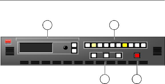
The figure below illustrates the DCS-200 front panel:
1 |
2 |
P R O G R A M : |
R G B |
|
SEL |
1 0 2 4 x 7 6 8 @ 5 9 . 9 4 |
|
|
|
N E X T : |
S D I |
A djust |
|
N T S C |
( 4 8 0 i ) |
ESC |
|
Inputs
1 |
2 |
3 |
4 |
5 |
6 |
7 |
8 |
S DI |
LO G O |
E ffects
FR Z |
BLA CK |
KE Y |
TA KE |
DCS-200
|
|
|
3 |
4 |
|
|
Figure 2-1. DCS-200 Front Panel |
|
|
|
|
|
|
|
|
|
|
1) |
Display Section |
3) |
Effects Section |
|
|
|
|
|
|
|
|
2) |
Inputs Section |
4) |
Take Button |
|
|
|
|
|
|
|
|
Following are descriptions of each front panel section:
1)Display Section
The Display Section includes a four-line display, the ADJUST knob and two “menu navigation” buttons: SEL and ESC. Refer to the “Display Section” heading on page 21 for complete details.
2)Inputs Section
The Inputs Section includes ten “source” buttons that enable you to select inputs, key sources and a full screen LOGO. Refer to the “Inputs Section” heading on page 22 for complete details.
3)Effects Section
The Effects Section provides three buttons that enable you to select the type of effect that you want to perform next. Refer to the “Effects Section” heading on page 23 for complete details.
4)Take Button
The red TAKE button initiates a transition to the selected source. Refer to the “Take” section on page 24 for details.
20 |
|
DCS-200 • User’s Guide |
|
2. Hardware Orientation
DCS-200 Front Panel
aблйд~у=pЙЕнбзе
The figure below illustrates the Display Section:
PROGRAM: |
RGB |
|
NEXT: |
1024x768 @59.94 |
|
SDI |
|
|
|
NTSC (480i) |
Adjust |
|
|
SEL |
ESC |
Figure 2-2. Display Section with sample Status Menu
Descriptions of each button and control are provided below:
•The Menu Display is a 4-line x 20-character Vacuum Fluorescent Display (VFD) that shows all DCS-200 menus and sub-menus. Brightness is adjustable. The following illustration shows a typical DCS-200 menu.
|
|
|
|
|
SETUP MENU |
|
|
|
> Trans Time |
1.0 |
|
|
Output |
>> |
|
|
Preview |
>> |
|
|
|
|
|
Figure 2-3. Sample Setup Menu Display
For all setup menus, please note:
~
~
The top line names the current menu, in all capital letters.
The navigation cursor (>) in the left-hand column indicates the current line on which action can be taken.
~The double arrow (>>) indicates that a sub-menu is available.
Note |
The Status Menu layout is different from the “setup” menu |
|
display. In Chapter 4, refer to the “Status Menu” section on |
|
page 44 for details. |
|
|
SEL |
In Chapter 4, refer to the “Menu Tree” section on page 38 for additional details on the system’s menu tree.
•ADJUST — use the Adjust Knob to scroll through all system menus.
~Turn the knob counter-clockwise (CCW) to scroll down.
~Turn the knob clockwise (CW) to scroll up.
•SEL — press to enter the setup menu tree (from the Status Menu), to enter a sub-menu, change a parameter, accept a parameter, or to answer “Yes” to certain menu queries.
DCS-200 • User’s Guide |
|
21 |
|
2. Hardware Orientation
DCS-200 Front Panel
|
• ESC — press to exit a menu without making changes, cancel an operation, to |
ESC |
answer “No” to certain menu queries, and to return to the top Status Menu. Each |
press takes you back up the menu tree by one level. |
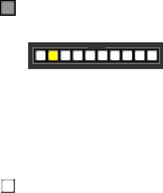
fеймнл=pЙЕнбзе
The figure below illustrates the Inputs Section:
|
|
|
|
|
Inputs |
|
|
|
|
1 |
2 |
3 |
4 |
5 |
6 |
7 |
8 |
SDI |
LOGO |
Figure 2-4. Inputs Section
The buttons in the Inputs Section enable you to select the source that you want to transition to Program. Each button corresponds to the similarly numbered input connector on the rear panel. You can also select the full screen LOGO as the transition source.
There are three button states:
•Off — the input is not selected for a transition.
•Blinking — the input is “pending” for the next transition.
~When a button is blinking fast, it is being acquired by the system.
~When a button is blinking slow, it is ready to be transitioned to Program.
Note |
If an input button is blinking slow, and the Status Menu |
|
shows “Invalid Signal,” the system has attempted to acquire |
|
the source, but has failed. |
|
|
•Lit Solid — the input is on Program.
In Chapter 4, refer to the “Flip-flop about button behavior when TAKE
Mode” section on page 85 for additional information is pressed.
Following are descriptions of each “input” button in the section:
|
• Buttons 1 through 6 enable you to select physical inputs 1 through 6 (respectively) |
|
|
||
1 |
from the rear panel HD-15 connectors. |
|
• Buttons 7 and 8 enable you to select physical inputs 7 and 8 (respectively) from |
||
|
||
|
the rear panel DVI-I connectors. Please note: |
|
|
||
|
~ If a DVI signal is present, the DVI (digital) source is used from the DVI-I |
|
|
connector’s digital pins. |
|
|
~ If a DVI signal is not present, the selection defaults to the analog signals |
|
|
that are on the DVI-I connector’s analog pins. Note that a customer- |
|
|
supplied DVI to HD-15 adapter is required to connect to the analog pins. |
22 |
|
DCS-200 • User’s Guide |
|
SDI |
LOGO |
2. Hardware Orientation
DCS-200 Front Panel
•The SDI button selects the SD-SDI or HD-SDI input source.
•The LOGO button selects the stored “full screen” LOGO image for the next transition. If no image is stored, the transition will be to Black. Use the menu to select one of three stored LOGOs for use. In Chapter 4, refer to the “Using the LOGO” section on page 88 for details.
Note |
If you press a button in the Inputs Section, it blinks to |
|
indicate “pending.” If you do not want to pend a source |
|
(which may be desirable in some situations), press the |
|
blinking source button again. The button turns off, leaving |
|
only the source on Program lit solid. |
|
|
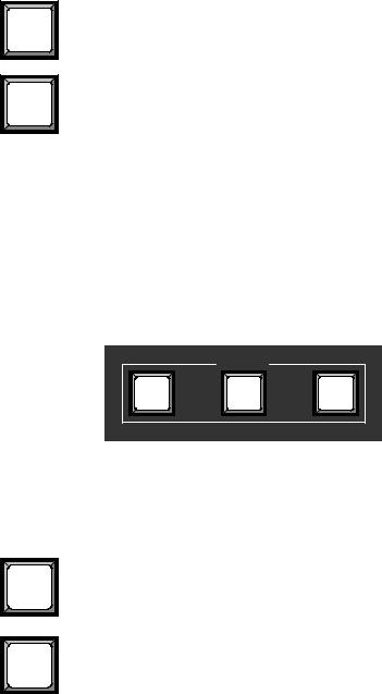
bССЙЕнл=pЙЕнбзе
The figure below illustrates the Effects Section:
|
Effects |
|
FRZ |
BLACK |
KEY |
Figure 2-5. Effects Section
The buttons in the Effects Section enable you to freeze the selected source on Program, transition to black, and perform a key over the selected Program source.
Following are descriptions of each “effects” button:
|
• The FRZ button instantly freezes and unfreezes the current Program source. |
FRZ |
When the source is frozen, the button is lit solid. In Chapter 4, refer to the “Using |
Freeze” section on page 92 for details. |
|
|
• The BLACK button enables you to transition to or from black. The button |
BLACK |
performs one of two functions, depending on the way the button is defined in the |
User Preferences Menu. |
|
|
~ If “Black Auto Take” is Off: |
|
• Press BLACK to pend a transition to or from black. The button |
|
blinks to indicate “pending.” |
|
• Press TAKE to perform the transition to or from black. |
|
– If the transition is “to” black, the button lights solid |
|
when black is on Program. |
|
– If the transition is “from” black, the button turns off |
|
when the selected source is fully on Program. |
DCS-200 • User’s Guide |
|
23 |
|
2. Hardware Orientation
DCS-200 Front Panel
~If “Black Auto Take” is On:
•Press BLACK to immediately transition to/from black.
–If the transition is “to” black, the button blinks fast during the transition, then lights solid when black is on Program.
–If the transition is “from” black, the button blinks fast during the transition, then turns off when the selected source is on Program.
|
Important |
Regardless of the current Black Auto Take mode, if you |
|
|
select (or pend) BLACK, the system will not transition to the |
|
|
selected “next” source until black is fully on Program. |
|
In Chapter 4, refer to the “Using Black” section on page 93 for details. |
|
|
• The KEY button enables you to key an un-scaled DVI source (input 7 or 8) over |
|
KEY |
the current Program source. The key’s clip, gain, opacity, and the selected key |
|
source are adjusted using the menu. The button performs one of two functions, |
||
|
depending on the way the button is defined in the User Preferences Menu. |
|
~If “Key Auto Take” is Off:
•Press KEY to pend a “key up” or “key down” transition. The button blinks to indicate “pending.”
•Press TAKE to perform the key transition at the current rate.
–If the transition is a “key up,” the button lights solid when the key is on.
–If the transition is a “key down,” the button automatically turns off when the key is off.
~If “Key Auto Take” is On:
•Press KEY to immediately perform the “key up” or “key down” transition at the current rate.
–If the transition is a “key up,” the button blinks fast during transition, then lights solid when the key is on.
–If the transition is a “key down,” the button blinks fast during transition, then turns off when the key is off.
|
In Chapter 4, refer to the “Using Keys” section on page 95 for details. |
|
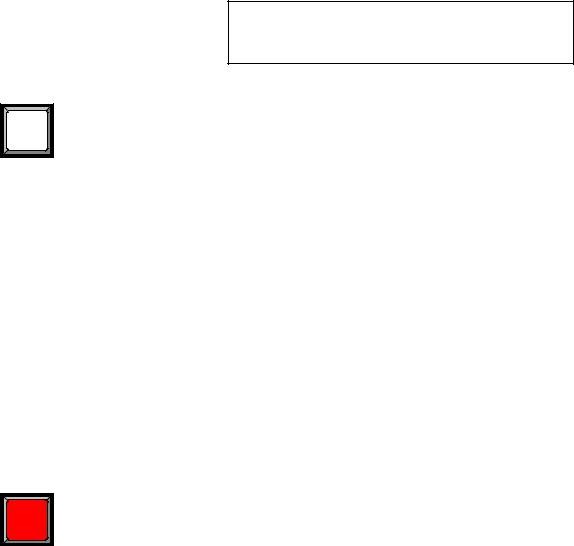
q~âÉ= |
|
Press TAKE to mix the pending (blinking) source to Program, at the current transition rate. |
TAKE |
Using the Setup Menu, you can adjust the transition time from 0 to 12 seconds. If the |
transition time is set to 0, the transition is a cut. Please note: |
|
|
• Each time TAKE is pressed, the current source on Program and the pending |
|
source flip-flop. In Chapter 4, refer to the “Flip-flop Mode” section on page 85 for |
|
additional details. |
•The TAKE button is also used to transition a “key” up or down, when the “Key Auto Take” function is On in the User Preferences Menu.
•The TAKE button is also used to transition to/from black, when the “Black Auto Take” function is On in the User Preference Menu.
In Chapter 4, refer to the “User Preference” section on page 70 for details on the User Preference Menu.
24 |
|
DCS-200 • User’s Guide |
|
2. Hardware Orientation
DCS-200 Rear Panel
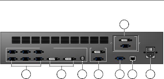
a`pJOMM=oÉ~ê=m~åÉä
The figure below illustrates the DCS-200 rear panel:
Input 1 |
Input 3 |
Input 5 |
VIDEO INPUTS |
MAIN OUTPUTS |
|
|
|||
|
|
|
|
HD/SD SDI |
Input 2 |
Input 4 |
Input 6 |
Input 7 |
Input 8 |
|
8 |
|
|
|
Model |
PREVIEW OUTPUTS |
DCS-200 |
|
|
||
|
|
100 - 240 VAC |
|
|
50 – 60 Hz, 1.9A |
SERIAL |
ETHERNET |
|
|
1 |
2 |
3 |
4 |
5 |
6 |
7 |
|
Figure 2-1. DCS-200 Rear Panel |
|
|
|
|
||
|
|
|
|
|
|
|
|
1) |
Analog Inputs |
4) |
Main Outputs |
|
7) |
AC Power |
|
|
|
|
|
|
|
|
|
2) |
DVI and Analog Inputs |
5) |
Serial |
|
8) |
Preview Outputs |
|
|
|
|
|
|
|
|
|
3) |
HD/SD SDI Input |
6) |
Ethernet |
|
|
|
|
|
|
|
|
|
|
|
|
Following are descriptions of each rear panel connector:
1)Analog Inputs
Six HD-15 connectors are provided for the system’s Analog inputs. Please note:
~Each input provides 10-bits/color sampling at a maximum 165 MHz.
~Each input supports 1:1 sampling up to 1600x1200@60 Hz. Sources with native pixel rates greater than 165 MHz will be filtered and undersampled at 165 Mhz. These include:
•1920x1080p@60 (173.0 MHz)
•1920x1200@60 (193.25 MHz)
•2048x1080p@60 (183.75 MHz)
~Composite and S-Video formats are supported.
In Chapter 3, refer to the “Format Connection Table” section on page 32 for a table of analog inputs that you can connect using a customer-supplied breakout cable. In Appendix A, refer to the “Analog 15-pin D Connector” section on page 118 for pinouts.
2)DVI and Analog Inputs
Two DVI-I connectors are provided for both digital and analog inputs.
~Using the connector’s digital pins, an 8-bit digital input is supported.
~Using the connector’s analog pins, RGBHV, analog composite, S-Video, and YUV formats are supported. A customer-supplied breakout cable or DVI to HD-15 adapter is required for these connections.
In Appendix A, refer to the “DVI-I Connector” section on page 119 for pinouts.
DCS-200 • User’s Guide |
|
25 |
|
2. Hardware Orientation
DCS-200 Rear Panel
3)HD/SD SDI Input
One BNC connector is provided for the SD-SDI or HD-SDI input.
4)Main Outputs
Two connectors are provided for the DCS-200’s main program outputs. Both outputs have the same resolution, and both can be used simultaneously.
~One DVI-I connector is provided for the system’s digital program output. There are no analog outputs on this connector. In Appendix A, refer to the “DVI-I Connector” section on page 119 for pinouts.
Note |
The DVI-I connector allows you to use both DVI-D and DVI-I |
|
cables as required. |
|
|
~One HD-15 connector is provided for the system’s analog output. In Appendix A, refer to the “Analog 15-pin D Connector” section on page 118 for pinouts
5)Serial
One DB-9 connector is provided for Serial communications with the DCS-200 system. The port is also used for diagnostics or command-line operations.
6)Ethernet
One RJ-45 connector is provided for 10/100BaseT Ethernet communications with the DCS-200 system. The port is used for running the built-in web-based GUI, for diagnostics, or for command-line operations via Telnet (using port 23).
S telnet 192.168.0.10 23
In Appendix A, refer to the “Ethernet Connector” section on page 120 for pinouts.
7)AC Power
One AC Connector is provided for connecting DCS-200 to AC. The integral switch turns the chassis on and off. In Appendix A, refer to the “Physical and Electrical Specifications” section on page 117 for power details.
8)Preview Outputs
Two outputs are provided for connecting to the Preview monitor: an HD-15 connector for analog monitors and a DVI connector for digital displays.
26 |
|
DCS-200 • User’s Guide |
|

PK==fåëí~ää~íáçå
få=qÜáë=`Ü~éíÉê
This chapter provides detailed instructions for installing the DCS-200 hardware. The following topics are discussed:
•
•
•
•
•
•
•
•
Safety Precautions
Unpacking and Inspection
Site Preparation
Cable and Adapter Information
Rack-Mount Installation
Power Installation
Signal Installation
Format Connection Table
DCS-200 • User’s Guide |
|
27 |
|

3. Installation
Safety Precautions
p~СЙну=mкЙЕ~мнбзел=
For all DCS-200 installation procedures, observe the following important safety and handling rules to avoid damage to yourself and the equipment:
•To protect users from electric shock, ensure that the power supplies for each unit connect to earth via the ground wire provided in the AC power cord.
•The AC Socket-outlet should be installed near the equipment and be easily accessible.
rей~ЕвбеЦ=~еЗ=fелйЙЕнбзе=
Inspect the shipping box for damage. If you find any damage, notify the shipping carrier immediately for all claims adjustments. As you open the box, compare its contents against the packing slip. If you find any shortages, contact your Barco sales representative.
Once you have removed all the components from their packaging and checked that all the listed components are present, visually inspect each unit to ensure there was no damage during shipping. If there is damage, notify the shipping carrier immediately for all claims adjustments.
páíÉ=mêÉé~ê~íáçå=
The environment in which you install your DCS-200 should be clean, properly lit, free from static, and have adequate power, ventilation, and space for all components.
`~ДдЙ=~еЗ=^З~йнЙк=fеСзкг~нбзе
The table below provides information regarding supplied cables and adapters:
Table 3-1. DCS-200 Cables and Adapters
Cable / Adapter |
Description |
Quantity |
AC Power Cord |
7 foot, 10A (US Power Cord) |
1 |
|
|
|
AC Power Cord |
7 foot, 10A (European Power Cord) |
1 |
|
|
|
28 |
|
DCS-200 • User’s Guide |
|

3. Installation
Rack-Mount Installation
o~ÅâJjçìåí=fåëí~ää~íáçå
DCS-200 units are designed to be rack mounted and are supplied with front rack-mount hardware. Please note the following important points:
•When rack mounting the unit, remember that the maximum ambient operating temperature for the unit is 40 degrees C.
•Leave sufficient front and rear space to ensure that the airflow through the fan and vent holes is not restricted.
•When installing equipment into a rack, distribute the units evenly to prevent hazardous conditions that may be created by uneven weight distribution.
•Connect the unit only to a properly rated supply circuit.
•Reliable grounding (earthing) of rack-mounted equipment should be maintained.
•Rack mount the unit from the front rack ears using four rack screws (not supplied). Rack threads may be metric or otherwise — depending upon the rack type.
•Install the lower of the two mounting holes first.
mçïÉê=fåëí~ää~íáçå
Use the following steps to install power to the DCS-200:
1.Connect an AC power cord to the AC Power Connector on the rear of the DCS-200, and then to an AC outlet.
2.Connect AC Power cords (or AC adapters) to all peripheral equipment, such as video sources, VTRs and PCs. Please note:
~Connect each unit only to a properly rated supply circuit.
~Reliable grounding of rack-mounted equipment should be maintained.
DCS-200 • User’s Guide |
|
29 |
|
3. Installation
Power Installation
mзпЙк=`зкЗLiбеЙ=sздн~ЦЙ=pЙдЙЕнбзе
DCS-200 is rated to operate with the following specifications:
•
•
Input Power: 100-240 VAC, 50-60 Hz
Power Consumption: 240 watts maximum
DCS-200 performs line voltage selection automatically, and no user controls are required. The AC power cords must be accessible so that they can be removed during field servicing.
Warning When the DCS-200 is used in the 230-volt mode, a UL listed line cord rated for 250 volts at 15 amps must be used and must conform to IEC-227 and IEC-245 standards. This cord will be fitted with a tandem prong-type plug.
The rear panel ON/OFF switch does not disconnect the unit from input AC power. To facilitate disconnection of AC power, the power cord must be connected to an accessible outlet near the unit.
Building Branch Circuit Protection: For 115 V use 20 A, for 230 V use 8 A.
Figure 3-1. Tandem Prong-type Plug
Avertissement La choix de la ligne de voltage se réalise automatiquement par le DCS-200 Transformateur Graphique. On n'a pas besoin du controller usager pour la choix de la ligne de voltage.
Warnung Das DCS-200 gerät mu beim Anschlu an 240V ~ mit einer vom VDE auf 250V/10A geprüften Netzleitung mit einem Schukostecker ausgestattet sein.
30 |
|
DCS-200 • User’s Guide |
|
 Loading...