


Awelco MIG ONE User Manual [ru]
PART 2
MIG ONE
I - Manuale D’uso
GB - User Manual
D - Bedienungsanleitung
F - Manuel D'utilisation
E - Manual De Usuario
P - ões
Manual De Instru
HU - Használati Utasítás
PL -
NL - Instructiehandleiding
RU - Эксплуацим
Руководство По
Instrukcja obsługi
USERMANUALUSERMANUAL
DK - Instruktionsmanual
(6)
(3)
(2)
(7)
(4)
VI RINGRAZIAMO PER AVER
SCELTO QUESTO PRODOTTO
THANKS FOR CHOOSING
OUR PRODUCT
(1) (5)(1) (5)
PARTE II - PART II - TEIL II - PARTIE II - PARTE II - PARTE II
RÉSZ II - CĘ ŚĆ II -Z DEEL II - ЧАСТЬ II - DEL II
MODEL
DATI TECNICI SALDATRICE / WELDING MACHINE TECHNICAL DATA / TECHNISCHE DATEN
SCHWEISSMASCHINE / DONNÉES TECHNIQUES POSTE DE SOUDAGE / DATOS TÉCNICOS DE
LA SOLDADORA / DADOS TÉCNICOS DO APARELHO DE SOLDAR / TECHNIKAI ADATOK / DANE
TECHNICZNE / TECHNISCHE GEGEVENS LASMACHINE / ТЕХИЧЕСКИЕ ДАННЫЕ
СВАРОЧНОГО АППАРАТА / TEKNISKE DATA SVEJSEMASKINE
PH
1~
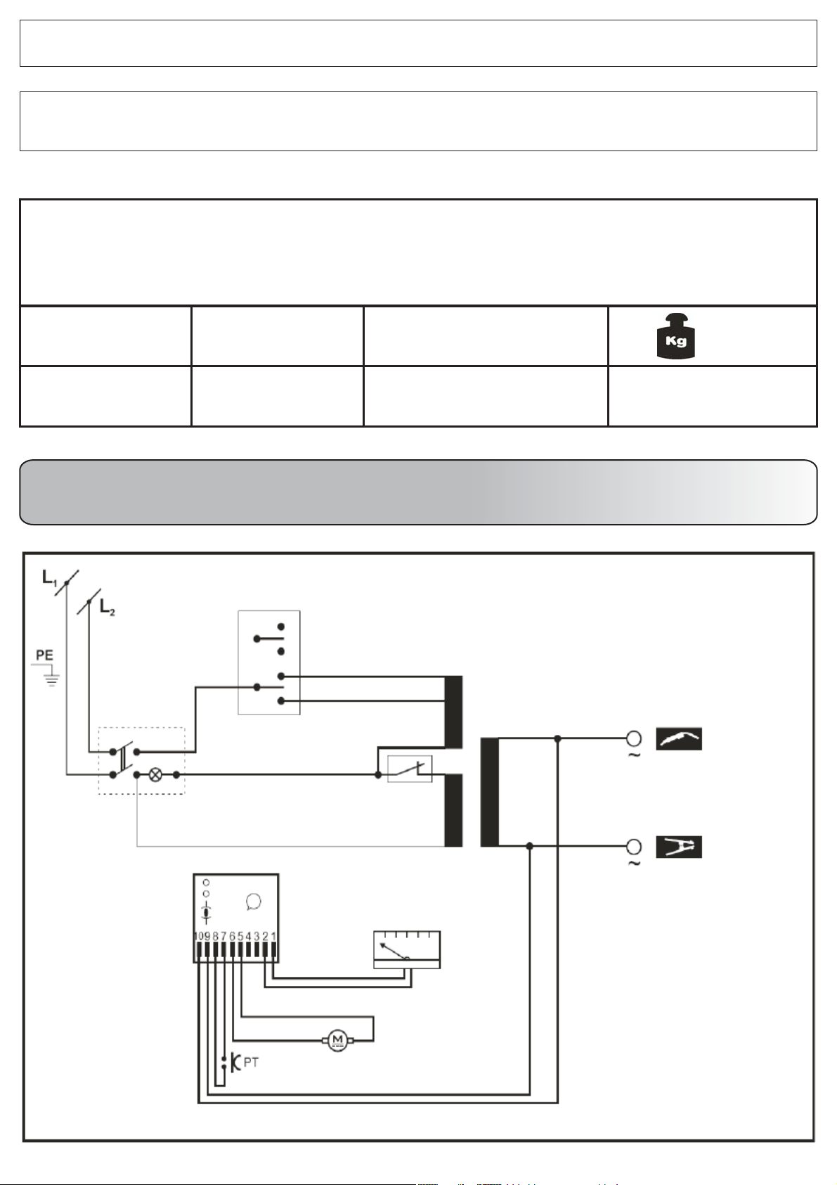
SCHEMA ELETTRICO - WIRING DIAGRAM - SCHALTPLAN - SCHÉMA ÉLECTRIQUE
ESQUEMA DE CONEXIONE - CONEXÃO REGIME - ELEKTROMOS BEKÖTES - SCHEMAT BLOKOWY
I
2 max
95
ELEKTRISCHSCHEMA - - ELDIAGRAMДИАГРАММА
MIG ONE
[A] [ ]
WxHxL
140 x 360 x 375
mm
[]
Kg
14-15

ITALIANO
DESCRIZIONE GENERALE
Saldatrici a filo continuo che salda filo animato senza gas.
PER UNA RESA OTTIMALE DELLA SALDATURA SI
CONSIGLIA DI UTILIZZARE DURANTE LA STESSA LO
SPAY PER SALDATURA PROMIG JET; IN TAL MODO SI
ESALTERANNO LE CARATTERISTICHE DI TENUTA,
OLTRE AD UNA AZIONE DI RIDUZIONE DEGLI SPRUZZI.
1. INSTALLAZIONE
1.1. CONNESSIONE ELETTRICA
La macchina è fornita di uno specifico cavo di alimentazione
che non dovrebbe essere prolungato; nel caso ciò fosse
necessario occorrerebbe usarne uno di sezione uguale a
quello della macchina.
Prima di collegare la saldatrice alla presa di corrente,
accertarsi che il voltaggio sia uguale a quello della macchina
e che la potenza erogata sia sufficiente ad alimentare la
macchina a pieno carico; accertarsi, inoltre, che l’impianto di
alimentazione sia provvisto di un adeguato sistema di messa
a terra.
Tensione di alimentazione
La tensione di alimentazione è di 230 V.
1.2. COLLEGAMENTO DELLA MASSA
La macchina è fornita di un cavo di massa collegato ad una
pinza. Verificare che ci sia un perfetto contatto tra la pinza e
il pezzo da saldare. Pulire bene i contatti in modo che non ci
siano grassi, ruggine o impurità. Un contatto non perfetto
riduce la capacità di saldatura e può causare, di
conseguenza, una saldatura non soddisfacente.
2. INFORMAZIONI TECNICHE SULLA SALDATRICE
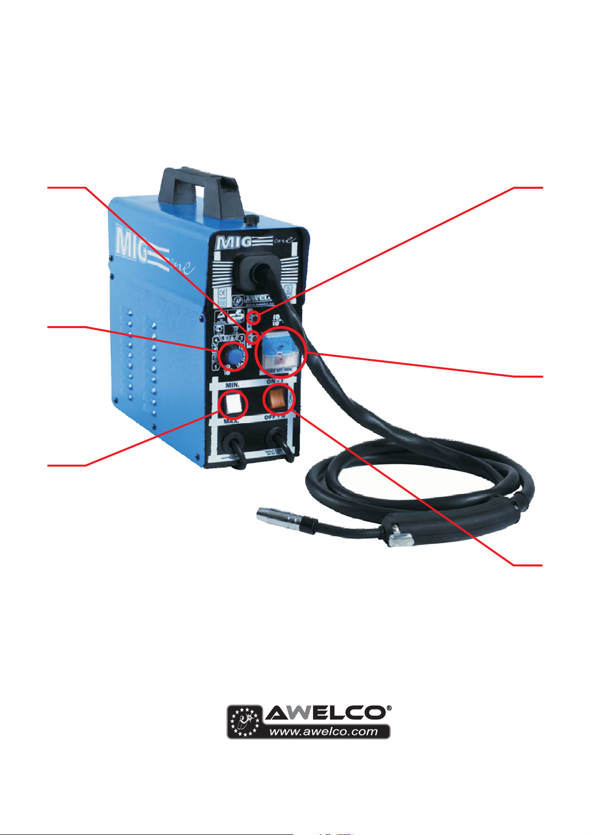
La saldatrice è dotata di un interruttore di linea On - Off (1),
con led luminoso che indica l’accensione della macchina (7).
La saldatrice dispone di un deviatore (2) che garantisce 2
posizioni di corrente; selezionare in base alla potenza di cui
si ha bisogno.
Utilizzando la manopola (3) posta sul frontale potete regolare
la velocità del filo. Tale manopola va usata insieme al
deviatore che regola l’amperaggio, in modo da ottenere un
arco scorrevole e perfetto.
E’ possibile visualizzare la velocità del filo mediante un
indicatore in M/min (4) posto sul pannello frontale della
macchina.
La saldatrice è dotata di un dispositivo di protezione termica
che interrompe automaticamente l’erogazione della corrente
di saldatura quando si raggiungono temperature elevate; in
tal caso si accende una spia luminosa (5). Quando la
temperatura si è sufficientemente abbassata e ha raggiunto il
livello che permette un corretto funzionamento della
saldatrice, la spia luminosa si spegne. La macchina è
alimentata automaticamente e si possono riprendere le
operazioni di saldatura.
La scheda di regolazione della macchina è protetta contro le
oscillazioni dell’alimentazione tramite un fusibile di facile
sostituzione posto sulla scheda di regolazione del filo. Nel
caso detto fusibile dovesse bruciarsi la macchina si blocca e
segnala l’anomalia tramite un led di colore giallo posto sul
frontale della macchina (6); per la sostituzione, dopo aver
tolto l’alimentazione alla macchina, svitare il pannello laterale
destro e sostituire il fusibile estraendolo facendo leva con un
piccolo cacciavite.
3. MODI DI SALDATURA
3.1. NO-GAS
La saldatrice è stata concepita per saldare con il
procedimento NO-GAS.
4. MONTAGGIO BOBINA FILO E TORCIA
4.1. MONTAGGIO BOBINA
Si possono adoperare bobine da 0.2 Kg, 0,4 Kg.
4.2. MOTORE TRAINAFILO
Assicurarsi che il rullino d’avanzamento filo abbia la cava di
diametro uguale a quella del filo. Le macchine sono
predisposte con rullino per filo Ø 0,6 e Ø 0,8. Per adoperare
filo Ø 0,9, è possibile utilizzare il rullino in dotazione. Il rullino
porta stampigliato sul fianco il Ø che si vuole adoperare. Le
macchine sono equipaggiate con rullini zigrinati adatti per
saldatura con filo animato senza gas di protezione. In ogni
caso la macchina salda solo con filo di tipo FLUX.
4.3. INSERIMENTO DEL FILO
Tagliare i primi 10 cm di filo assicurandosi che l’estremità
presenti un taglio netto senza sporgenze, distorsioni o
impurità. Rialzare la rotella collegata al braccio mobile
svitando l’apposita vite. Inserire il filo nella guida di plastica
facendolo passare sulla scanalatura appropriata del rullino e
quindi reinserirlo nella guida. Assicurarsi che il filo non sia
teso ma sia in posizione naturale. Abbassare il braccio e
regolare la pressione mediante l’apposita vite. La pressione
corretta è quella che consente l’avanzamento regolare del
filo e, nello stesso tempo, qualora il filo si inceppi, la ruota
motrice deve slittare senza fare aggrovigliare il filo stesso. E’
possibile regolare anche la frizione dell’aspo. Se l’aspo gira a
vuoto, aumentare la frizione in modo che la bobina sia
sempre in tiro. Se invece la frizione crea troppo attrito e la
ruota motrice tende a slittare, è necessario diminuirla fino ad
ottenere un regolare avanzamento del filo.
4.4. COLLEGAMENTO DELLA TORCIA
La torcia è collegata direttamente e, quindi è già pronta per
l’uso. Una eventuale sostituzione va fatta con molta cura. E’
preferibile farla eseguire da un tecnico esperto. Per sostituire
la punta guida gas è sufficiente svitare oppure tirare verso
l’esterno. La punta guida gas va tolta ogni qual volta bisogna
sostituire l’ugello guidafilo. Tale ugello deve essere sempre
del diametro appropriato a quello del filo. Tenere sempre
perfettamente pulita la punta guida gas.
5. GUIDA ALLA SALDATURA
5.1. REGOLA GENERALE
Quando la saldatura è regolata al minimo è necessario che
la lunghezza dell’arco sia piccola. Questo si ottiene tenendo
la torcia il più vicino possibile al pezzo da lavorare e con una
inclinazione di circa 60 gradi. La lunghezza dell’arco può
essere aumentata man mano che si aumenta l’intensità di
corrente, al massimo si può arrivare ad una distanza di circa
20mm.
5.2. CONSIGLI DI CARATTERE GENERALE
Di tanto in tanto alcuni difetti si possono verificare nella
saldatura. Questi difetti si possono eliminare prestando
attenzione ad alcuni suggerimenti che qui di seguito Vi
proponiamo:
- Porosità
Piccoli fori nella saldatura, non dissimili da quelli della
superficie della cioccolata, possono essere causati da
interruzione del flusso di gas o talvolta dall’in-clusione di
piccoli corpi estranei. Il rimedio usuale è molare la saldatura
e rifare la saldatura. Prima, però, bisogna controllare il flusso
di gas (circa 8 litri/minuto), pulire benissimo la zona di lavoro
e poi inclinare correttamente la torcia mentre si salda.
- Spruzzatura
Piccole gocce di metallo fuso che provengono dall’arco di
saldatura.
In piccole quantità è inevitabile, ma si può ridurre al minimo
regolando bene la corrente ed il flusso di gas e tenendo
pulita la torcia.
- Saldatura stretta e arrotondata
È causata dall’avanzamento veloce della torcia oppure dal
gas non regolato bene.
- Saldatura spessa e larga
Può essere causata da un avanzamento troppo lento della
torcia.
- Filo bruciato dietro
Può essere causato da un avanzamento del filo lento, dalla
punta guidafilo allentata o consumata, filo di bassa qualità,

beccuccio guidagas troppo chiuso o corrente troppo elevata.
- Scarsa penetrazione
Può essere causata da un avanzamento troppo veloce della
torcia, da corrente troppo bassa, da alimentazione del filo
non corretta, da polarità invertita, smussi e distanza tra i
lembi insufficiente. Curare la regolazione dei parametri
operativi e migliorare la preparazione dei pezzi da saldare.
- Foratura del pezzo
Può essere causata dal movimento troppo lento della torcia,
corrente troppo elevata o non corretta alimentazione del filo.
- Forte spruzzatura e porosità.
Può essere causato da una distanza eccessiva del
beccuccio guidagas dal pezzo, da sporco sui pezzi, da
scarso flusso di gas o da corrente bassa. Bisogna verificare i
due parametri, ricordando che il gas non deve essere
inferiore a 78 litri/min. e che la corrente di saldatura deve
essere appropriata al diametro del filo che si sta utilizzando.
E’ preferibile avere un riduttore di pressione di entrata e di
uscita. Sul manometro di uscita è possibile leggere anche la
portata espressa in litri.
- Instabilità d’arco
Può essere causata da tensione insufficiente, avanzamento
filo irregolare, gas di protezione insufficiente.
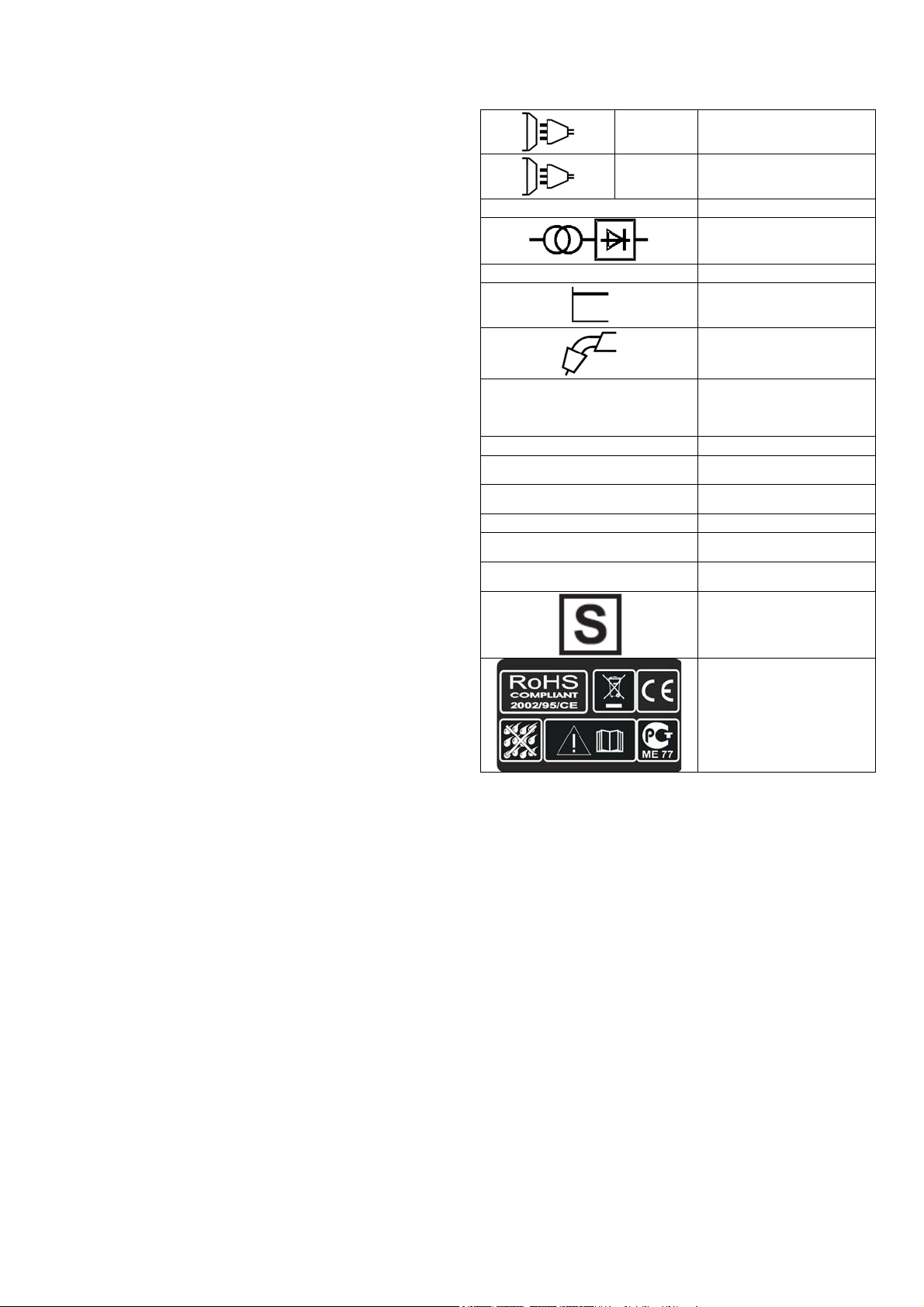
SIGNIFICATO DELLE SCRITTE E DEI SIMBOLI
EN 60974 - 1
U 1 … (V/Hz)
I 2 … (A)
I
… (A)
1 max
I
… (A)
1 eff
X
IP21
H
Trasformatore raddrizzatore
Norma di riferimento
Caratteristica piatta
Saldatura a filo MIG-MAG
Valore nominale della
tensione di alimentazione e
della frequenza
Corrente di saldatura
Corrente massima assorbita
Corrente effettiva di
alimentazione
Duty cycle
Grado di protezione della
saldatrice
Classe di isolamento del
trasformatore
Saldatrice adatta all’uso in
un ambiente con rischio
accresciuto di scosse
elettriche
1 ~
3 ~
U 0 … (V)
GUASTO
Il filo non avanza quando
la ruota motrice gira
Alimentazione del filo a scatti o
intermittente
Arco spento
Cordatura di saldatura poroso
Alimentazione monofase
Alimentazione trifase
Valore nominale della
tensione di uscita a vuoto
RICERCA DEL GUASTO
RAGIONI
1) Sporco sulla punta
dell’uggello guida filo
2) La frizione dell’aspo
svolgitore è eccessiva
3) Torcia difettosa
1) Ugello di contatto difettoso
2) Bruciature nell’ugello
di contatto
3) Sporco sul solco della ruota
motrice
4) Solco sulla ruota motrice
consumato
1) Cattivo contatto tra pinza di
massa e pezzo
2) Corto circuito tra ugello di
contatto e tubo guidagas
1) Mancanza dello scudo di gas
causato da incrostazioni
nell’ugello guidagas
2) Distanza o inclinazione
sbagliata della torcia
3) Troppo poco gas
4) Pezzi umidi
Simboli riferiti a norme di
sicurezza
Soffiare con aria
Allentare
Controllare guaina guidafilo
Sostituire
Sostituire
Pulire
Sostituire
Stringere la pinza e controllare
Pulire oppure sostituire ugello di contatto e
ugello guidagas
Pulire dalle incrostazioni o sostituire
La distanza tra la torcia e il pezzo deve
essere di 5 - 10 mm; l’inclinazione non
meno di 60° rispetto al pezzo
Aumentare la quantità
Asciugare con una pistola ad aria calda o
RIMEDI

La macchina cessa improvvisamente
di funzionare dopo un uso prolungato
5) Pezzi con molta ruggine
1) La macchina si è surriscaldata
per un uso eccessivo e la
protezione
termica è intervenuta
ENGLISH
GENERAL DESCRIPTION
MIG welders which can weld flux cored gasless wire.
WHEN WELDING, USE PROMIG JET WELDING SPRAY
TO OBTAIN OPTIMAL WELDING. THE USE OF THIS
PRODUCT WILL ENHANCE THE BINDING OF THE WELD
AND REDUCE SPATTERING.
1. INSTALLATION
1.1. ELECTRICAL CONNECTION
The welding machine is fitted with a suitable primary cable
which we strongly recommend you to do not extend: if it is
necessary to extend it, use a cable having the same section
of the primary cable.
Before connecting the machine to the outlet, check that your
supply voltage is like the machine’s voltage and that the
furneshed power is sufficient to feed the full load machine.
Make sure that the electric plant is provided with a sufficient
earth connection.
Supply voltage
The supply voltage is of 230V.
1.2. EARTH CONNECTION
A suitable earth cable connected to a clamp is supplied with
the welding machine. The earth clamp should be attached to
the workpiece itself. The must be very good connection
wherever made, as a poor or dirty connection will produce
difficult welding conditions and could result in a bad weld.
2. TECHNICAL INFORMATION
The welding machine has an On-Off switch (1), with
luminous led that indicates the operation of the car (7).
The welder has a switch (2) that provides 2-position power,
to select based on the power of which need is had.
Using the knob (3) placed on the frontal you can regulate the
welding wire speed. The knob should be used in conjunction
with the voltage switch to give a smooth and perfect arc.
You can see the speed of the wire through an indicator in
M/min (4) on the front panel of the machine.
The machine is fitted with a thermal overload protection
which will automatically interrupt the welding current on
reaching excessive temperatures; in which instance a yellow
pilot light (5) will switch on. Once the temperature has
decreased to a level low enough to allow welding, the light
will switch itself off and the machine is again ready for use.
The wire speed control electronic card is protected against
peak of voltage by means of an easy to repalce fuse located
on the wire setting card. Should said fuse burn, the machine
will stop automatically and the malfunction will be signalled
by a led located on the machine’s front panel (6). In order to
change the burnt fuse, disconnect the machine from tha
mains, unscrew the right side panel and replace the fuse by
pulling it out. Use a small screwdriver to lever the fuse out. In
any case do not connect the welding machine to the power
generator.
3. WELDING MODE
3.1. NO-GAS
The machine was designed for NO-GAS welding.
4. SPOOL WIRE AND TORCH INSTALLATION
4.1. SPOOLS INSTALLATION
You can use spools of Kg. 0,2 , Kg. 0,4.
4.2. WIRE-FEEDER MOTOR
Make sure that the size of the groove in the feed roll
corresponds to the welding wire size being used. The
machines are arranged with feed roll for Ø 0,6 and 0,8 wire.
altro mezzo
Pulire i pezzi dalla ruggine
Lasciare raffreddare la macchina per
almeno 20 – 30 minuti
Used for wire Ø 0.9, you can use the supplied roll. The feed
roll has the wire diameter stamped on its side. The machines
are equipped with proper shagreneed rolls suitable for
welding with flux cored wire without gas protection. In any
case, the machine uses only wire type FLUX.
4.3. FEEDING WIRE INTO THE WELDING TORCH
Cut the first 10 cm of wire and then check that there are no
burrs or distortions at the cut end. Release the small wheel
which is connected to the pressure arm by unscrewing the
pressure screw and pass the wire through the feed roll’s
groove and then re-insert the wire into the guide. At this
point, make sure that the wire lies in the feed roll’s groove in
a natural line. Drop the pressure arm on the wire and swing it
back under the pressure screw. Pressure on the welding wire
is regulated by turning the pressure screw, the correct
pressure being critically important to the smooth operation of
the welding machine. The optimum pressure is the one
which ensures that the wire runs smoothly though allows the
feed roll to slip in the event of a blockage in the torch. It is
possible to adjust the friction of the paddle hub. If the hub
over-runs, then increase the friction pressure in order to
always have the spool wire drawn. On the contrary, if the
friction pressure is too much, some tension can be released
to obtain a regular wire feeding.
4.4. TORCH CONNECTION
The torch is connected directly to the welding machine so it
is ready for use. A probable replacement of the torch must
be done with care and if possible by a technician. To replace
contact tips, it is necessary to unscrew or to pull it. Replace
tip, check that it corresponds with the wire size and replace
the gas shroud. For good wire feeding during welding
operations, it is essential that the correct size parts are used
for each wire. Keep always clean the contact tip.
5. WELDING GUIDE
5.1. GENERAL RULE
When welding on the lowest output settings, it is necessary
to keep the arc as short as possible. This should be achieved
by holding welding torch as close as possible and at an
angle of approximately 60 degrees to the workpiece. The arc
length can be increased when welding on the highest
settings, an arc length up to 20 mm can be enough when
welding on maximum settings.
5.2. GENERAL WELDING TIPS
From time to time, some faults may be observed in the weld
owing to external influences rather due to welding machine’s
faults. Here are some that you may come across :
· Porosity
Small holes in the weld, caused by break-down in gas
coverage of the weld or sometimes by foreign bodies
inclusion. Remedy is, usually, to grind out the weld.
Remember, check before the gas flux (about 8
liters/minutes), clean well the working place and finally
incline the torch while welding.
· Spatter
Small balls of molten metal which come out of the arc. A little
quantity is unavoidable, but it should be kept down to a
minimum by selecting correct settings and having a correct
gas flow and by keeping the welding torch clean.
· Narrow heap welding
Can be caused by moving the torch too fast or by an
incorrect gas flow.

· Very thick or wide welding
Can be caused by moving the torch too slowly.
· Wire burns back
It can be caused by wire feed slipping, loose or damaged
welding tip, poor wire, nozzle held too close to work or
voltage too high.
· Little penetration
It can be caused by moving torch too fast, too low voltage
setting or incorrect feed setting, reversed polarity, insufficient
blunting and distance between strips. Take care of
operational parameters adjustment and improve the
preparation of the workpieces.
· Workpiece’s piercing
It may be caused by moving the welding torch too slow, too
high welding power or by an invalid wire feeding.
· Heavy spatter and porosity
It can be caused by nozzle too far from work, dirt on work or
by low gas flow. You have to the two parameters, remeber
that gas has not to be lower than 7-8 liters/ min. and that the
current of welding is appropriated to the wire you are using. It
is advisable to have a pressure reducer of input and output.
On the manometer you can read the range expressed in liter.
· Welding arc instability
It may be caused by an insufficient welding voltage, irregular
wire feed, insufficient protective welding gas.
DESCRIPTION OF SIGNS AND SYMBOLS
3 ~
U 0 … (V)
FAULT
1 ~
Wire isn’t conveyed when
Feed roll is turning
Wire feeding in jerk or
erratic way
No arc
Porous welding seams
The machine suddenly stops welding
operations after an extended and heavy
duty use
Single phase alternating
voltage
Three phase alternating
voltage
Nominal open circuit
voltage
FAULT FINDING
REASON
1) Dirt in liner and/or contact tip
2) The frition brake in the hub
is too tightened
3) Faulty welding torch
1) Contact tip defect
2) Burns in contact tip
3) Dirt in feed roll groove
4) Feed roll’s groove worn
1) Bad concat between earth clamp
and workpiece
2) Short-circuit between contact tip
and gas shroud
1) Failre of gas shield owing to
spatters in gas shro
2) Wrong welding torch distance
and/or inclination from workpiece
3) Too small gas flux
4) Humid workpieces
5) Heavily rusted workpieces
1) Welding machine overheated due
to an excessive use in stated duty
cycle
Transformer-rectifier
EN 60974-1
U 1 … (V/Hz)
I 2 … (A)
I
(A)
1 max
I
… (A)
1 eff
X
IP21
H
Blow with compressed air, replace contact
tip
Loosen
Check sheating of torchès
wire guide
Replace
Replace
Clean
Replace
Tighten earth clamp and check connections
Clean, replace tip and/or shroud as
necessary
Clean gas shroud from spatters
The length of stick out wire from tip must
be 5 – 10mm. Inclination not less than 60
degrees in relation to woekpiece
Increase flux of welding gas
Dry with heat producer
Clean workpieces from rust
Don’t switch off the machine, let it cool
down for about 20/30 minutes
Norm of reference
Flat characteristic
MIG-MAG wire feed
welding
Nominal values of mains
voltage and frequency
Welding current
The welding unit's
maximum absorbed
current
Effective current supplied
Duty cycle
The welding unit's
protection class
The transformer's
insulation class.
Welding machine suitable
for use in environments
with heightened risk of
electric shock.
Symbols referring to safety
regulations
REMEDY

DEUTSCH
ALLGEMEINE BESCHREIBUNG
Schutzgasschweissanlagen für das Verschweissen von
Fülldraht ohne Gas.
1. INSTALLATION
1.1. ELEKTRISCHE VERBINDUNGEN
Die Schweißmaschine hat ein eigenes bestimmtes
Speisekabel, das lang genug ist, um nicht verlängert werden
zu müssen. Sofern jedoch eine weitreichendere Verbindung
benötigt wird, ist es unbedingt erforderlich , ein
Verlängerungskabel zu benutzen, das dem der
Schweißmaschine gleich ist.
Bevor die Schweißmaschine an eine Steckdose
angeschlossen wird, muß überprüft werden, ob die
Spannung der der Schweißmaschine gleich ist und ob die
Leistungsabgabe ausreichend für eine Vollast des Gerätes
ist. Außerdem ist es unbedingt nötig festzustellen, ob die
Speiseanlage mit einem ausreichenden Erdungssystem
ausgestattet ist.
Zuführungspannung
Ist die Speisespannung 230 V.
1.2. ERDVERBINDUNG
Die Schweißmaschine wird schon mit einem geeigneten
Erdungskabel, das mit einer Zange verbunden ist, geliefert.
Achten Sie darauf, daß die Zange einen leistungsfähigen
Kontakt mit dem zu schweißenden Teil hat. Die Kontakte
müssen von Schmierfett, Rost und Verschmutzungen
gereinigt und geschützt werden. Ein nicht leistungsfähiger
Kontakt vermindert die Schweißkapazität und somit wird das
Ergebnis der erfolgten Schweißung nicht perfekt sein.
2. TECHNISCHE INFORMATIONEN BEZÜGLICH DER
SCHWEIßMASCHINE
Die Schweißmaschine hat einen On - Off Schalter (1), mit
einer LED-Leuchte, welche anzeigt, dass die Maschine
eingeschalten ist (7). Die Schweißmachine hat einen
Schalter (2) für 2 Strompositionen, welche aufgrund der
gebrauchten Leistung ausgewählt werden.
Mit dem Knopf (3) auf der Vorderseite können Sie die
Drahtgeschwindigkeit wählen. Dieser Knopf wird zusammen
mit dem Stromumstellungsknopf verwendet, um einen
reibungslosen und perfekten Bogen zu erhalten.
Sie können die Geschwindigkeit des Drahtes durch eine
Anzeige in m/min (4) auf der Vorderseite der Maschine
erkennen.
Das Schweißgerät ist mit einer Thermoschutzeinrichtung
ausgerüstet, die den Schweißstromzufluß automatisch
unterbricht, sobald eine höhere Temperatur erreicht wird (5).
In diesem Fall leuchtet ein gelbes Warnlicht auf. Sobald die
Temperatur wieder auf einen für den Betrieb geeigneten
Wert absinkt, schaltet das Warnlicht aus. Der Stromzufluß
wird automatisch wiederaufgenommen und das
Schweißgerät ist wieder betriebsbereit.
Die Regulationsplatine der Maschine ist gegen
Speiseschwankungen durch eine leicht ersetzbare
Sicherung, welche sich auf der Drahtregulationsplatine
befindet. Für den Fall, dass die Sicherung durchbrennt,
stoppt die Maschine und zeigt diese Anomalie durch einen
gelben LED (6) auf, welcher sich auf der Vorseite der
Maschine befindet. Für die Ersetzung der Sicherung , die
Maschine ausstecken, die rechte Seitenwand abschrauben
und die Sicherung austauschen, mit einem kleinen
Schraubendreher hebend.
3. SCHWEIßARTEN
3.1. NO-GAS SCHWEIßUNG
Die Schweißmaschine wurde entwickelt, um ohne GAS
schweissen zu können.
4. EINBAU DER DRAHTSPULE UND DES
SCHLAUCHPAKETS
4.1. EINBAU DER DRAHTSPULE
Auf der Maschine können Drahtspulen von 0,2 Kg, 0,4 Kg
verwendet werden.
4.2. DRAHTVORSCHUBMOTOR
Versichern Sie sich, daß die Furche der Drahtvorschubspule
den gleichen Durchmesser des Drahtes hat. Die
Schweißgeräte sind von vorherein mit einer Drahtspule für
Drähte von 0,6 und 0,8 Durchmesser vorgesehen. Für Draht
Ø 0.9, können Sie die mitgelieferte Rolle verwenden.
Auf der Seitenfläche der Spule ist der zu gebrauchende
Durchmesser gedruckt. Die Schweißgeräte sind mit
gerändelten Rollen versehen für das Fülldrahtschweissen
ohne Schutzgas. Die Maschine schweisst mit FLUX-Draht.
4.3. EINFÜHRUNG DES DRAHTES
Die ersten 10 cm des Drahtes müssen so abgeschnitten
werden, daß ein gerader Schnitt, ohne Vorsprünge,
Verziehungen und Verschmutzungen erhalten wird.
Heben Sie die Rolle, die mit dem beweglichen Arm
verbunden ist, indem Sie die entsprechende Schraube lösen.
Setzen Sie den Draht in die Plastikführung ein, indem Sie ihn
durch die entsprechende Furche ziehen und ihn somit wieder
in die Führung einlegen. Es ist zu beachten, daß der Draht
nicht gespannt, sondern auf natürliche Weise eingelegt wird.
Senken Sie den beweglichen Arm wieder und regeln Sie den
Druck mit Hilfe der entsprechenden Schraube. Der richtige
Druck bewirkt einen regelmäßigen Durchlauf des Drahtes
und selbst wenn der Draht sich verklemmen sollte, treibt er
das Antriebsrad so an, daß es ohne Schwierigkeiten
weitergleitet. Bei den Schweißgeräten kann man auch die
Wicklerkupplung regulieren. Sofern der Wickler leerlaufen
sollte, muß die Kupplung jedoch erhöht werden, damit die
Spule ständig gespannt ist. Sollte die Kupplung eine zu
starke Reibung hervorrufen und sollte das Antriebsrad
anfangen zu gleiten, ist es unbedingt erforderlich die
Kupplung herunterzuschrauben bis es zu einer regelmäßigen
Drahtführung kommt.
4.4. VERBINDUNG DES SCHLAUCHPAKETS
Das Schlauchpaket ist direkt verbunden und somit schon
gebrauchsfähig. Ein eventueller Austausch muß mit extremer
Vorsicht, oder besser direkt von einem Fachmann
vorgenommen werden. Um die Gasausgangsspitze
auszutauschen ist es ausreichend, diese abzuschrauben
oder nach außen zu ziehen. Die Gasausgangsspitze ist
jedesmal rauszunehmen, wenn die Drahtvorschubdüse
ausgetauscht werden muß. Es ist zu beachten, daß der
Durchmesser der Düse immer dem des Drahtes gleich ist.
Die Gasausgangsspitze muß ständig saubergehalten
werden.
5. SCHWEIßANLEITUNG
5.1. ALLGEMEINE REGEL
Bei einer Schweißung, die auf das Minimum gestellt ist, ist
es wichtig darauf zu achten, daß die Länge des Lichtbogens
kurz ist. Dieses ergibt sich sofern man den Schweißbrenner
mit etwa 60 Grad Neigung so nah wie möglich an den zu
schweissenden Teil hält. Die Länge des Lichtbogens kann
verringert werden, indem man nach und nach die
Stromstärke erhöht. Dabei kann es auch zu einem Abstand
von zirca 20mm kommen.
5.2. ALLGEMEINE RATSCHLÄGE
Von Zeit zu Zeit ist es durchaus möglich Mängel bei der
Schweissung festzustellen. Diese Mängel können jedoch
vermieden werden, sofern die folgenden Ratschläge
beachtet werden:
· Porosität
Kleine Löcher in der Schweißnaht, ( ähnlich denen der
Oberfläche der Schokolade ) verursacht durch die
Unterbrechung des Gasflusses oder durch das Eindringen
von kleinen Fremdkörpern. Das gebräuchlichste Mittel ist das
Schleifen und Wiederschweißen der Schweißarbeit. Bevor
die Schweißarbeit erneut ausgeführt wird, kontrollieren Sie,
daß der Gasfluß ( ca. 8l/min.) korrekt eingestellt ist und daß
das Werkstück frei vor Verschmutzungen ist . Darauf achten,
daß der Schweißbrenner beim Schweißen richtig geneigt
wird.
· Bespritzung
Kleine, geschmolzene Metalltropfen , die vom Lichtbogen
hervorgerufen werden. In kleinen Mengen ist es
unvermeidbar, aber es kann auf ein Minimum reduziert
werden, wenn der Strom - und Gasfluß genau eingestellt
werden und der Schweißbrenner immer saubergehalten
wird.
· Schmale und abgerundete Schweißnaht
Die Ursache ist eine zu schnelle Führung des
Schweißbrenners oder ein nicht gut geregelter Gasfluß.
· Dicke und breite Schweissnaht
Die Ursache kann eine zu langsame Führung des
Schweißbrenners sein.
· Drahtenende angebrannt
Kann durch ein zu langsamer Vorschub des Drahtes, durch
gelockerte oder abgenutzte Kabelführungsspitze, geringe
Kabelqualität, durch eine zu geschlossene Gasrohrspitze
oder ein zu hoher Stromfluß verursacht werden.
· Geringes Eindringen der Schweißnaht
Kann durch ein zu schnelles Führen des Schweißbrenners,
eine zu niedrige Stromspannung, ein nicht korrekt
funktionierender Drahtvorschub, durch umgekehrte Polarität,
Abstumpfungen und unzureichender Abstand zwischen den
Limbus verursacht werden. Auf die Einstellung der
operativen Parameter achten und die Vorbereitung der
Werkstücke verbessern.
· Durchlöcherung des Werkstücks
Kann durch eine zu langsame Führung des
Schweißbrenners, eine zu hohe Stromspannung oder ein
nicht funktionsgerechter Drahtvorschub verursacht werden.
· Starke Bespritzung und Porosität
Kann durch eine übermäßige Distanz des Gasbrenners vom
Werkstück verursacht werden, Schmutz auf den
Werkstücken oder ein zu knapper Gasfluß. Der Gasfluß muß
nicht geringer als 7-8 Liter/ min. sein und der Schweißstrom
muß dem benutzten Drahtdurchmesser entsprechen. Es ist
ratsam, einen Eingang- und Ausgangdruckregler zu haben.
Auf dem Ausgangsmanometer kann man auch die
Fördermenge in Liter ablesen.
· Unbeständiger Lichtbogen
Die Ursachen sind eine unzureichende Stromspannung,
unregelmäßiger Drahtvorschub und nicht ausreichender
Schutzgas.
ART
Der Draht wird von der Drahtführungsrolle
nicht weitergeführt
Unregelmäßige Drahtführung
Der Lichtbogen erlischt
1) Gasführungsdüse verschmutzt
2) Drahtrollenhalterung zu stark
3) Schweißbrenner ist defekt
1) Kontaktdüse ist defekt
2) Brandspuren an der Kontaktdüse
3) Verschmutzung der Führungsrille
4) Führungsrille auf der
1) Unzureichender Kontakt zwischen
STÖRUNGSSUCHE
oder Leitugsdraht an die
Gasführungsdüse geklebt.
Drahtrolle verschmutzt
gespannt
der Drahtführungsrolle
Drahtführungsrolle abgenutzt
Werkstück und Massekabel
BESCHREIBUNG DER ZEICHEN UND DER SYMBOLE
1 ~
Wechselspannung einphasig
Wechselspannung
dreiphasig
Maximale Leerlaufspannung
Gleichrichtertransformator
Norm des Hinweises
flache Eigenschaft
Drahtschweißung MIG MAG
Dieses Symbol bedeutet
nominale Speisespannung
und nominale Frequenz der
Leitung
Schweißstrom
Maximale Stromaufnahme
der Leitung
Tatsächliche
Stromversorgung
Einschaltdauer
Schutzklasse des
Schweißgerätes
Isolationsklasse des Transformators
Schweißmaschine geeignet
zur Benutzung in
Umgebungen mit erhöhter
Stromschlaggefahr
Symbole mit Bezug auf
Sicherheitsnormen
STÖRUNG
DER
3 ~
U 0 … (V)
EN 60974 - 1
U 1 … (V/Hz)
I 2 … (A)
I
… (A)
1 max
I
… (A)
1 eff
X
IP21
H
Drahtrolle mit Druckluft reinigen
Gasführungsdüse austauschen
Befestigungsrädchen etwas lösen
Drahtführung kontrollieren
auswechseln
auswechseln
reinigen
auswechseln
Kontakt zwischen Massekabel und
Werkstück überprüfen und verbessern

Poröse Schweißnaht
Das Gerät hört nach längerem Gebrauch
plötzlich auf zu funktionieren
Das Gerät wurde durch zu langen Gebrauch
überhitzt und durch den Thermoschutz
automatisch abgeschaltet
2) Kurzschluß zwischen Kontaktdüse
und Gasführungsdüse
1) Schutzgasmangel hervorgerufen
durch Schmutz in der
Gasführungsdüse
2) Falscher Abstand oder
Neigungswinkel beim Führen des
Schweißbrenners
3) Geringer Gasfluß
4) Feuchte Werkstücke
5) Stark verrostete Werkstücke
FRANÇAIS
DESCRIPTION GENERALE
Poste de soudage a fil continu permettant le soudage, avec
fil fourré sans gaz.
POUR UNE PERFORMANCE OPTIMALE DE LA
SOUDURE EST AVISÉE LORS DE L'UTILISATION DE LA
MEME POUR LE SOUDAGE SPAY PROMIG JET DE
CETTE FAÇON EST EXALTE LES ELEMENTS DE DROIT,
EN OUTRE, A UNE ACTION DE REDUCTION DES JETS.
1. INSTALLATION
1.1. CONNEXION ÉLECTRIQUE
L’appareil est fourni d’un câble de courant approprié qui ne
doit pas être prolongé. Au cas où c’est nécessaire, se fournir
d’un câble de section égale à celle de l’appareil.
Avant de brancher l’appareil à une prise de courant,
s’assurer que le voltage soit égal à celui de l’appareil et que
la puissance fournie soit suffisante à alimenter l’appareil à
plein régime; s’assurer, en outre, que le réseau
d’alimentation soit pourvu d’un système conforme de mise à
terre.
Voltage d’alimentation
Le voltage d’alimentation est de 230 V.
1.2. CONNEXION A LA MASSE
L’appareil est fourni avec un câble de masse relié à une
pince. Vérifier que le contact de la pince avec la piéce à
souder soit efficace. Bien nettoyer le contact de façon à ce
qu’il n’y ait ni graisse ni rouille ni impuretés. Un mauvais
contact peut réduire la capacité de soudage et la soudure
n’est pas satisfaisante.
2. INFORMATIONS TECHNIQUES DU POSTE A SOUDER
Le soudeur a une ligne d'alimentation On - Off (1), avec des
LED indique que l'allumage de la voiture (7).
Le soudeur a un commutateur (2) veille à ce que les 2
postes de pouvoir, de sélectionner sur la base de la
puissance dont vous avez besoin.
Utilisation de la molette (3) situé sur la face avant, vous
pouvez ajuster la vitesse du fil. Ce bouton est utilisé avec la
dérivation, qui réglemente l'ampérage en vue d'obtenir une
bonne et parfaite arc.
Elle est possible visualiser la vitesse du fil au moyen d'un
indicateur en M/min (4) place sur le panneau frontal de la
machine.
Le poste à souder est équipé d’un dispositif de protection
thermique qui coupe automatiquement le débit de courant de
soudage lorsqu’on atteint des températures élevées; dans ce
cas, un voyant lumineux s’allume (5). Quand la température
diminue suffisamment et rejoint un niveau qui permet un
correct fonctionnement du poste, le témoin lumineux jaune
Kontaktdüse und Gasführungsdüse
reinigen oder austauschen
Reinigen oder auswechsein
Der Abstand zwischen Schweißbrenner
und Werkstückl iegt zwischen 5 – 10 mm.
Der Neigungswinkel zum Werkstück sollte
nicht weniger als 60° sein
Gasfluß erhöhen
Mit Warmluftpistole trocknen
Werkstücke vorn Rost befreien
Das Gerät etwa 20 – 30 min abkühlen
lassen
s’éteint et le poste, automatiquement alimenté par le courant
électrique, est à nouveau prêt à souder
Les détails de réglage de la machine est protégée contre les
fluctuations de l'alimentation par le biais d'un simple fusible
de remplacement siège au conseil d'administration de
l'ajustement du fil. Dans le cas où le fusible était en feu
bloque la machine et indique les anomalies par le biais d'un
voyant jaune sur le siège avant de la volture (6), pour le
remplacement, après la suppression de la puissance de la
machine, dévissez le panneau de droite et de remplacer le
fusible de l'extraction de levier avec un petit tournevis.
3. MODES DE SOUDAGE
3.1. NO-GAS
4. MONTAGE DE LA BOBINE DE FIL ET DE LA TORCHE
4.1. MONTAGE DE LA BOBINE
L’on peut utiliser des bobines de 0,2 Kg, 0,4 Kg.
4.2. MOTEUR D’ENTRAÎNEMENT DU FIL
Assurez -vous que le galet d’avancement du fil ait rainure du
même diamètre que celui di fil à utiliser. Les postes sont
préparés avec un galet d’avancement du fil de Ø 0,6 et Ø
0,8; Utilisé pour le fil de Ø 0.9, vous pouvez utiliser le
rouleau.
Le diamètre du fil que le galet est apte à utiliser est
estampillé sur son côté. Les postes sont équipés de galets
crénelés pour la soudure de fil fourré sans gaz de protection.
En tout cas, la machine uniquement avec du fil solide type
FLUX.
4.3. COMMENT INTRODUIRE LE FIL DANS LA TORCHE
Couper les premiers 10 cm. du fil en s’assurant que
l’extrémité ait une coupe nette sans saillies, distorsions ni
impuretés. Soulever le petite roue liée au bras mobile en
dévissant la vis appropriée.Introduire ensuite le fil dans la
coulisse en le faisant passer dans la rainure du galet, puis le
réintroduire dans la coulisse. S’assurer que le fil ne soit ni
trop tendu ni trop relâché. Baisser le bras mobile et régler la
pression avec la vis appropriée. La pression exacte est celle
qui permet au fil d’avancer régulièrement et en même temps
d’empêcher la roue motrice de glisser et de l’emmêler. Il est
posssible de régler le frottement du dévidoir. Si celui-ci
tourne à vide, augmentez le frottement de façon à ce que la
bobine soit toujours serrée. Si, au contraire, le frottement
cause trop de friction et la roue motrice tend à glisser, il faut
la diminuer jusqu’à obtenir un avancement du fil régulier.
4.4. CONNEXION DE LA TORCHE
La torche est reliée d’une manière directe, donc elle est déjà
prête à l’emploi. S’il est nécessaire de la changer, il faut le
faire avec beaucoup d’attention. Il est préférable de faire
 Loading...