


Awelco BLUEMIG 145 User Manual [ru]

ITALIANO
DESCRIZIONE GENERALE
Saldatrici a filo continuo con possibilità di saldare filo animato senza gas
o con gas per la saldatura di acciaio, inox e alluminio.
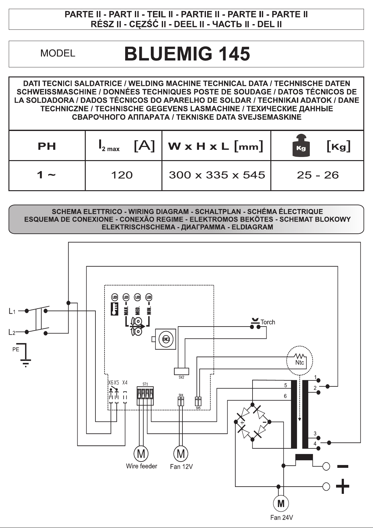
1. INFORMAZIONI TECNICHE SULLA SALDATRICE
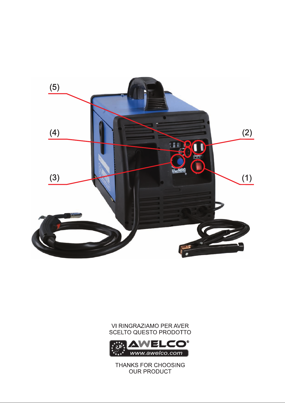
Per mettere in funzione la saldatrice agire sull’interruttore generale
ON/OFF (1).
L’intensità della corrente di saldatura erogata è regolabile per mezzo di
due deviatori (2).
La velocità del filo si regola mediante la manopola di variazione della
velocità (3). Tre leds rossi visualizzano il livello della velocità (4).
La saldatrice è dotata di un dispositivo di protezione termica che
interrompe automaticamente l’erogazione della corrente di saldatura
quando si raggiungono temperature elevate; in tal caso si accende una
spia luminosa gialla (5). Quando la temperatura si è sufficientemente
abbassata e ha raggiunto il livello che permette un corretto
funzionamento della saldatrice, la spia luminosa gialla si spegne. La
macchina è alimentata automaticamente e si possono riprendere le
operazioni di saldatura.
2. INSTALLAZIONE
2.1. CONNESSIONE ELETTRICA
La macchina è fornita di uno specifico cavo di alimentazione che non
dovrebbe essere prolungato; nel caso ciò fosse necessario occorrerebbe
usarne uno di sezione uguale a quello della macchina.
Prima di collegare la saldatrice alla presa di corrente, accertarsi che il
voltaggio sia uguale a quello della macchina e che la potenza erogata sia
sufficiente ad alimentare la macchina a pieno carico; accertarsi, inoltre,
che l’impianto di alimentazione sia provvisto di un adeguato sistema di
messa a terra.
Tensione di alimentazione
La tensione di alimentazione è di 230 V.
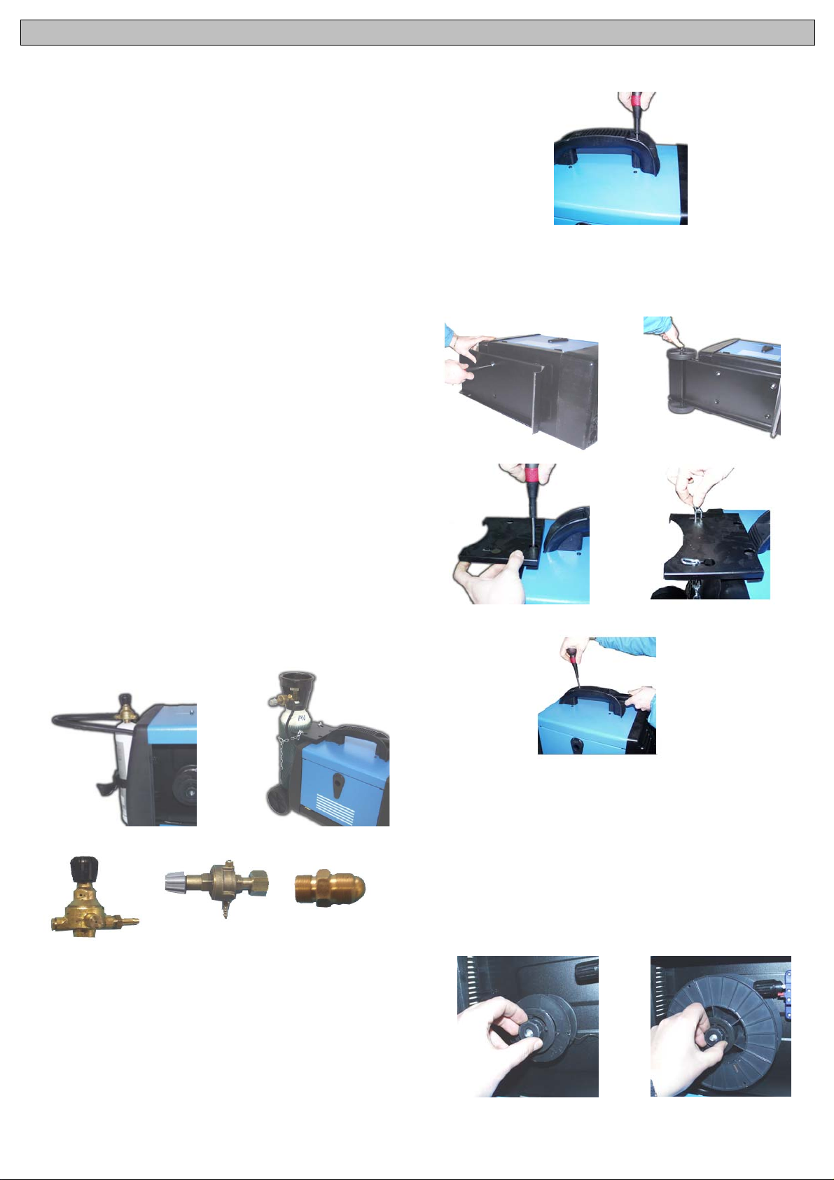
2.2. COLLEGAMENTO DEL GAS (PER I MODELLI PREDISPOSTI)
La bombola del gas deve essere posta nell’apposito vano porta-bombola
nella parte posteriore della macchina sull’apposita piattaforma. Nel
collegamento alla bombola verificare che tutti gli attacchi siano ben
serrati.
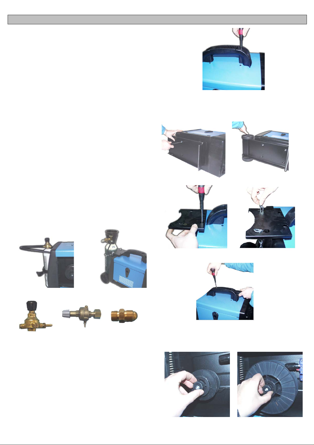
Posizionare la bomboletta da 1Kg. di gas (Opzionale) sul retro della
macchina nell’apposita sede e serrate con le cinghie in dotazione (Fig.1).
Se la macchina è equipaggiata con una bombola di gas da 5Kg.
(Opzionale), dopo aver montato il kit ruote posizionare la bombola sul
supporto e serrare con la catena (Fig.2).
Se usat e il CO
Chiedetelo al vostro rivenditore.
, è possibile che abbiate bisogno di un adattatore.
2
2.4. MONTAGGIO MANIGLIA
Montare la maniglia secondo la figura usando le viti in dotazione.
2.5. MONTAGGIO KIT RUOTE (OPTIONAL)
Alcuni modelli sono dotati di un kit ruote comprendente: Piedino
d’appoggio, pianale, assale, portabombola, catena di fissaggio, maniglia
di trascinamento, 2 ruote in plastica e due tappi o coppiglie di bloccaggio.
Seguire lo schema seguente per il montaggio del kit.
Fig. 2
Regulatore 1 Kg Regulatore 5 Kg Adattatore CO
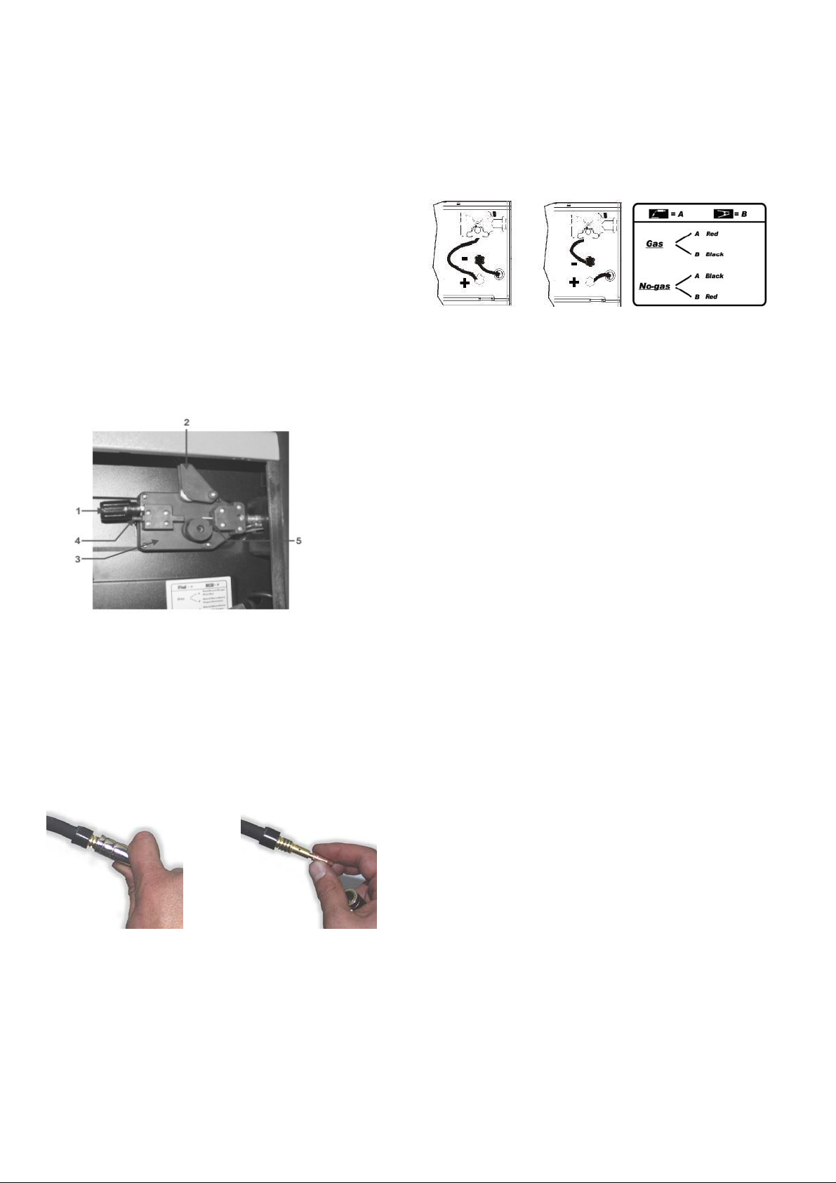
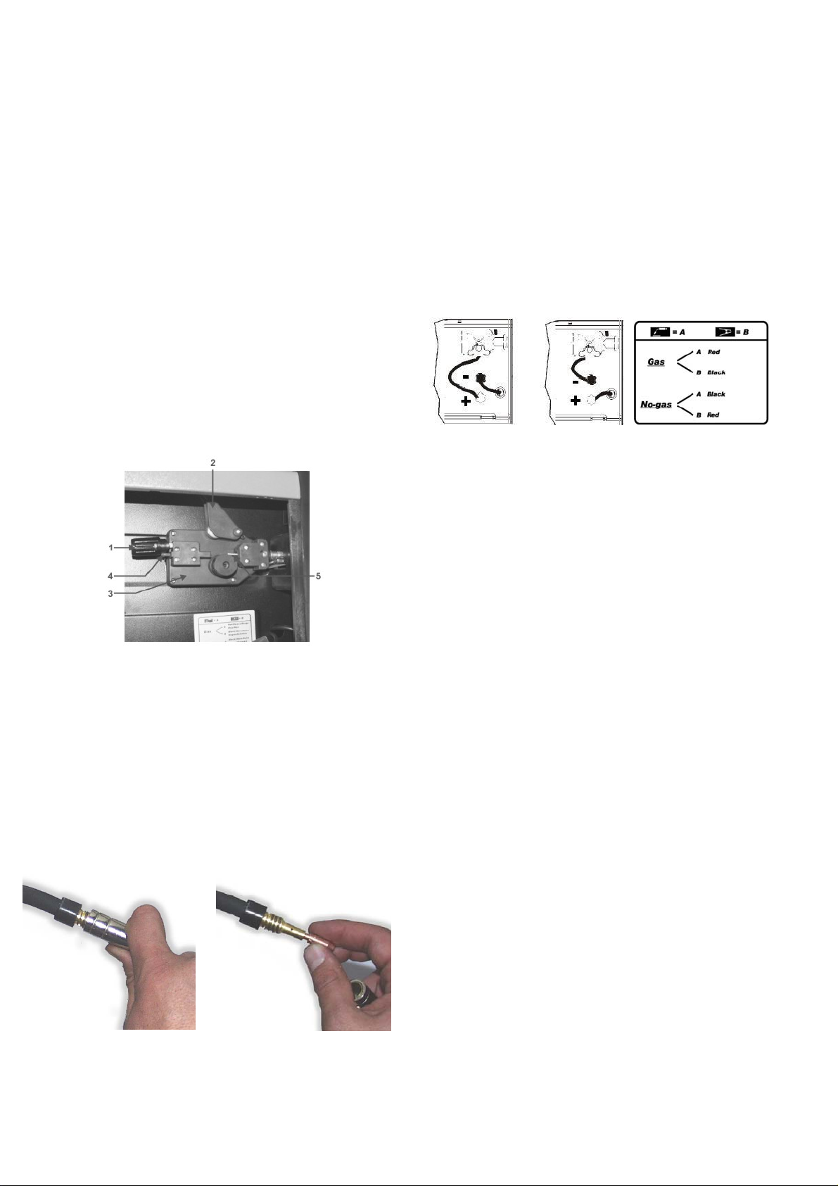
2.3. COLLEGAMENTO DELLA MASSA
La macchina è fornita di un cavo di massa collegato ad una pinza.
Verificare che ci sia un perfetto contatto tra la pinza e il pezzo da saldare.
Pulire bene i contatti in modo che non ci siano grassi, ruggine o impurità.
Un contatto non perfetto riduce la capacità di saldatura e può causare, di
conseguenza, una saldatura non soddisfacente. Il terminale della pinza
di massa va inserito nell’uscita polo positivo (+) per il procedimento di
saldatura senza gas; va inserito, invece, nell’uscita polo negativo (-) per il
procedimento di saldatura con gas.
Fig. 1
2
Per il montaggio ruote seguire le seguenti istruzioni:
1. Introdurre l’assale negli appositi fori sul fondo posteriore della
carrozzeria.
2. Collegare le ruote all’assale.
3. Bloccare le ruote con le coppiglie o con i tappi di bloccaggio.
4. Fissare il supporto anteriore con le viti parker date in dotazione
5. Fissare il prolungamento maniglia avvitandolo sulla maniglia fissa in
corrispondenza del foro.
3. MONTAGGIO BOBINA, FILO E TORCIA
3.1. MONTAGGIO BOBINA
Le macchine possono utilizzare indifferentemente bobine da ø100 e
ø200. L’aspo possiede una frizione, al fine di mantenere sempre il filo
rigido.
ø100
ø200
3.2. MOTORE TRAINAFILO
Assicurarsi che il rullino d’avanzamento filo abbia la cava di diametro
uguale a quella del filo. Il rullino porta stampigliato sul fianco il diametro
del filo che si può adoperare. Per saldare con filo pieno con GAS di
protezione sostituire il rullino del gruppo trainafilo con rullino con
scanalatura avente forma V per il filo in acciaio e a forma di U per il filo di
alluminio. Richiedere tali rullini e il riduttore di pressione al vostro
rivenditore di fiducia o alla società costruttitrice se si intende usare la
saldatrice con gas di protezione.
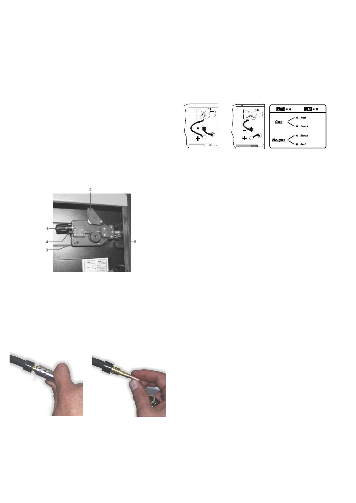
3.3. INSERIMENTO DEL FILO
1. Disinnestare il braccetto con molla (1) e ruotarlo verso l’alto (2) in
modo da allontanarlo dal rullino (3). Assicuratevi che il rullino porti
stampigliato nel lato a vista il diametro del filo che si sta usando.
2. Con attenzione staccare il filo dalla bobina portafilo. Per evitare noiosi
sbobinamenti tenerlo in tensione fino al punto (5).
3. Tagliare i primi 100 mm di filo o comunque tutta la parte non
perfettamente diritta.
4. Inserire il filo nella guida (4), sopra il rullino (3) e quindi inserirlo nel
tubo capillare (5).
5. Chiudere il braccetto premifilo lasciando la molla caricata. Ruotare la
bobina in modo da allentare ulteriormente il filo.
6. La manopola di regolazione della pressione del filo è regolata a metà
pressione. Nel caso la pressione sia eccessiva (rischio di appiattire il filo),
svitare la manopola in modo da ridurre la pressione. Una pressione
maggore è richiesta nel caso si usi filo da 0,6 mm. Se il rullino guida
slitta, bisogna aumentare la pressione fino a che il filo avanzi
regolarmente.
7. Togliere l’ugello guida gas e la punta di contatto.dalla pistola della
torcia.
8. Metter l’interruttore in posizione “ON” (“ I “).
9. Tirare il cavo della torcia in modo che sia ben diritto.
10.Premere il pulsante della torcia ed alimentare il filo fino a che ess o
appaia all’estremità della torcia (attenzione non puntare la pistola contro
voi o altre persone), quindi rilasciare il pulsante.
11.Spegnere la macchina mettendoin posizione “OFF” ( “O”).
12.Riposizionare la punta di contatto e l’ugello gas.
13.Tagliare il filo di 6-10 mm oltre la punta. Ora la macchina è pronta per
saldare.
3.4. COLLEGAMENTO DELLA TORCIA
La torcia è collegata direttamente e, quindi è già pronta per l’uso. Una
eventuale sostituzione va fatta con molta cura. E’preferibile farla eseguire
da un tecnico esperto. Per sostituire la punta guida gas è sufficiente
svitare oppure tirare verso l’esterno. La punta guida gas va tolta ogni
qual volta bisogna sostituire l’ugello guidafilo. Tale ugello deve essere
sempre del diametro appropriato a quello del filo. Tenere sempre
perfettamente pulita la punta guida gas.
4. MODI DI SALDATURA
4.1. SALDATURA IN CONTINUO
E’ il sistema maggiormente adoperato. Una volta preparata la macchina
è sufficiente premere il pulsante della torcia ed iniziare le operazioni di
saldatura. Per smettere di saldare è sufficiente rilasciare il pulsante della
torcia.
4.2. PRESSIONE DEL GAS
La pressione del gas va regolata in modo che l’erogazione corrisponda
ad un valore compreso tra i 6 e i 12 litri.
4.3. SALDATURA GAS – NO GAS
4.3.1. Gas – Collegare il morsetto della torcia nell’uscita positiva “+” e la
pinza della massa nell’uscita negativa “-”.
4.3.2. No-Gas – (Solo per i modelli che hanno questa predisposizione)
Effettuare il cambio di polarità, collegare, quindi, la pinza della massa
nella connessione positiva “+” e il morsetto della torcia nella connessione
negativa “-”.
4.4. SALDATURA MIG - MAG
A) MIG = Metal Inert Gas
B) MAG = Metal Active Gas
I due procedimenti sono perfettamente equivalenti, ciò che cambia è il
tipo di gas adoperato. Nel caso A il gas adoperato è l’ARGON (gas
inerte). Nel caso B il gas adoperato e il CO
(gas attivo). Per saldare le
2
leghe d’alluminio o d’inox è necessario adoperare ARGON puro o al
massimo una miscela composta dall’80% di ARGON e dal 20% di CO
Si può adoperare la CO
da sola soltanto nel caso di saldatura di acciaio
2
.
2
al carbonio (ferro).
5. GUIDA ALLA SALDATURA
5.1. REGOLA GENERALE
Quando la saldatura è regolata al minimo è necessario che la lunghezza
dell’arco sia piccola. Questo si ottiene tenendo la torcia il più vicino
possibile al pezzo da lavorare e con una inclinazione di circa 60 gradi. La
lunghezza dell’arco può essere aumentata man mano che si aumenta
l’intensità di corrente, al massimo si può arrivare ad una distanza di circa
20mm.
5.2. CONSIGLI DI CARATTERE GENERALE
Di tanto in tanto alcuni difetti si possono verificare nella saldatura. Questi
difetti si possono eliminare prestando attenzione ad alcuni suggerimenti
che qui di seguito Vi proponiamo:
- Porosità
Piccoli fori nella saldatura, non dissimili da quelli della superficie della
cioccolata, possono essere causati da interruzione del flusso di gas o
talvolta dall’in-clusione di piccoli corpi estranei. Il rimedio usuale è molare
la saldatura e rifare la saldatura. Prima, però, bisogna controllare il flusso
di gas (circa 8 litri/minuto), pulire benissimo la zona di lavoro e poi
inclinare correttamente la torcia mentre si salda.
- Spruzzatura
Piccole gocce di metallo fuso che provengono dall’arco di saldatura.
In piccole quantità è inevitabile, ma si può ridurre al minimo regolando
bene la corrente ed il flusso di gas e tenendo pulita la torcia.
- Saldatura stretta e arrotondata
È causata dall’avanzamento veloce della torcia oppure dal gas non
regolato bene.
- Saldatura spessa e larga
Può essere causata da un avanzamento troppo lento della torcia.
- Filo bruciato dietro
Può essere causato da un avanzamento del filo lento, dalla punta
guidafilo allentata o consumata, filo di bassa qualità, beccuccio guidagas
troppo chiuso o corrente troppo elevata.
- Scarsa penetrazione
Può essere causata da un avanzamento troppo veloce della torcia, da
corrente troppo bassa, da alimentazione del filo non corretta, da polarità
invertita, smussi e distanza tra i lembi insufficiente. Curare la regolazione
dei parametri operativi e migliorare la preparazione dei pezzi da saldare.
- Foratura del pezzo
Può essere causata dal movimento troppo lento della torcia, corrente
troppo elevata o non corretta alimentazione del filo.
- Forte spruzzatura e porosità.
Può essere causato da una distanza eccessiva del beccuccio guidagas
dal pezzo, da sporco sui pezzi, da scarso flusso di gas o da corrente
bassa. Bisogna verificare i due parametri, ricordando che il gas non deve
essere inferiore a 78 litri/min. e che la corrente di saldatura deve essere
appropriata al diametro del filo che si sta utilizzando. E’ preferibile avere
un riduttore di pressione di entrata e di uscita. Sul manometro di uscita è
possibile leggere anche la portata espressa in litri.
- Instabilità d’arco
Può essere causata da tensione insufficiente, avanzamento filo
f
irregolare, gas di protezione insufficiente.
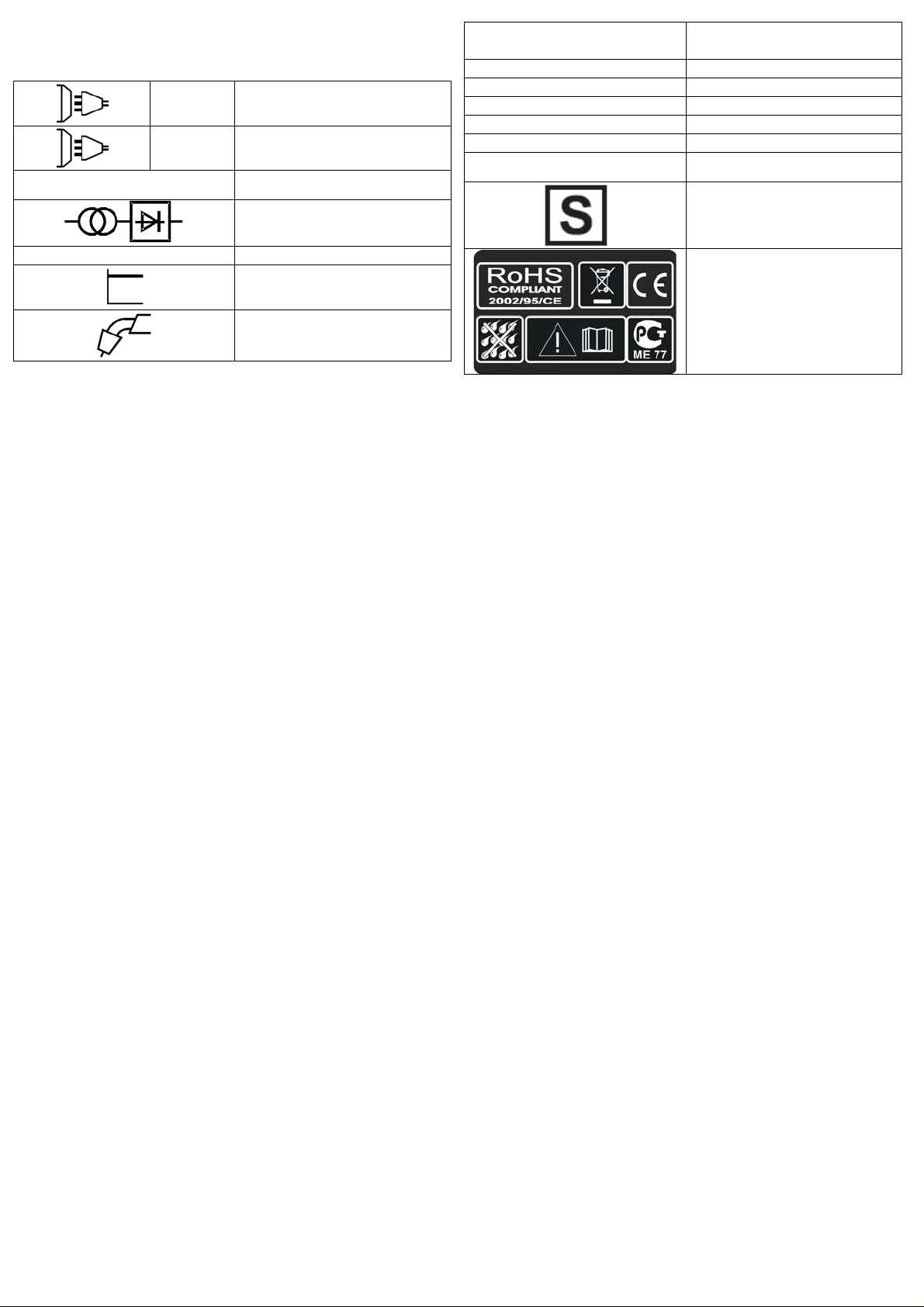
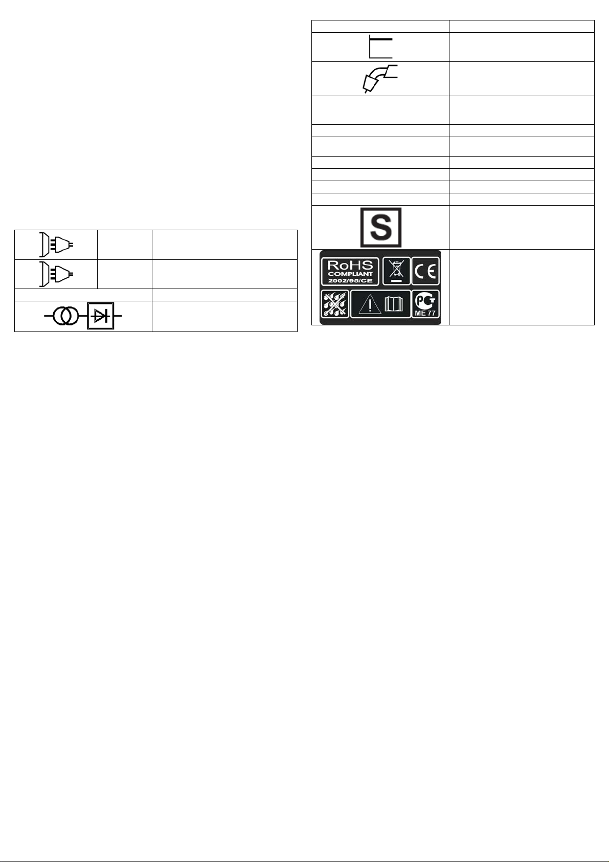
SIGNIFICATO DELLE SCRITTE E DEI SIMBOLI
1 ~
Alimentazione monofase
3 ~
U 0 … (V)
GUSTO
EN 60974 - 1
Il filo non avanza quando
la ruota motrice gira
Alimentazione del filo a scatti o
intermittente
Arco spento
Cordatura di saldatura poroso
La macchina cessa improvvisamente
di funzionare dopo un uso prolungato
Alimentazione trifase
Valore nominale della tensione di
uscita a vuoto
Trasformatore raddrizzatore
Norma di riferimento
Caratteristica piatta
Saldatura a filo MIG-MAG
RICERCA DEL GUASTO
RAGIONI
1) Sporco sulla punta
dell’uggello guida filo
2) La frizione dell’aspo
svolgitore è eccessiva
3) Torcia difettosa
1) Ugello di contatto difettoso
2) Bruciature nell’ugello
di contatto
3) Sporco sul solco della ruota
motrice
4) Solco sulla ruota motrice
consumato
1) Cattivo contatto tra pinza di
massa e pezzo
2) Corto circuito tra ugello di
contatto e tubo guidagas
1) Mancanza dello scudo di gas
causato da incrostazioni
nell’ugello guidagas
2) Distanza o inclinazione
sbagliata della torcia
3) Troppo poco gas
4) Pezzi umidi
5) Pezzi con molta ruggine
1) La macchina si è surriscaldata
per un uso eccessivo e la
protezione termica è intervenuta
U 1 … (V/Hz)
I 2 … (A)
I
… (A)
1 max
I
… (A)
1 ef
X
IP21
H
Valore nominale della tensione di
alimentazione e della frequenza
Corrente di saldatura
Corrente massima assorbita
Corrente effettiva di alimentazione
Duty cycle
Grado di protezione della saldatrice
Classe di isolamento del
trasformatore
Saldatrice adatta all’uso in un
ambiente con rischio accresciuto di
scosse elettriche
Simboli riferiti a norme di sicurezza
RIMEDI
Soffiare con aria
Allentare
Controllare guaina guidafilo
Sostituire
Sostituire
Pulire
Sostituire
Stringere la pinza e controllare
Pulire oppure sostituire ugello di contatto
e
ugello guidagas
Pulire dalle incrostazioni o sostituire
La distanza tra la torcia e il pezzo deve
essere di 5 - 10 mm; l’inclinazione non
meno di 60° rispetto al pezzo
Aumentare la quantità
Asciugare con una pistola ad aria calda o
altro mezzo
Pulire i pezzi dalla ruggine
Lasciare raffreddare la macchina per
almeno 20 – 30 minuti
ENGLISH
GENERAL DESCRIPTION
MIG welders which can weld flux cored gasless wire or with gas for the
welding ofmild steel, stainless steel and aluminium.
1. TECHNICAL INFORMATION
To switch on the welding machine operate the main switch (1).
The intensity of the supplied welding current can be adjusted by means
of two switches (2).
The wire speed regulation occurs through the knob of the encoder
(3).Three red leds show the actual speed (4).
The machine is fitted with a thermal overload protection which will
automatically interrupt the welding current on reaching excessive
temperatures; in which instance a yellow pilot light will switch on (5).
Once the temperature has decreased to a level low enough to allow
welding, the yellow light will switch itself off and the machine is again
ready for use.
2. INSTALLATION
2.1. ELECTRICAL CONNECTION
The welding machine is fitted with a suitable primary cable which we
strongly recommend you to do not extend: if it is necessary to extend it,
use a cable having the same section of t he primary cable.
Before connecting the machine to the outlet, check that your supply
voltage is like the machine’s voltage and that the furneshed power is
sufficient to feed the full load machine. Make sure that the electric plant is
provided with a sufficient earth connection.
Supply voltage
The supply voltage is of 230V.
2.2. GAS CONNECTION (FOR MODELS WHERE PROVIDED)
The gas bottle should be placed on the suitable platform provided at the
rear of the welding machine and secured with the retaining chain
provided, or in case of the remaining models, it should be placed on the
platform. Verify that all connections are well closed.
Place the 1 Kg. gas bottle (OPTIONAL) in the rear side and clamp the
belt (Pic.1). If the machine is equipped by a 5 kg gas (OPTIONAL), after
the wheel kit procedure has been done (see wheel kit assemblage) place
the gas bottle on the support and lock with the chain (Pic.2).
If CO
gas is used, it is possible that a CO2 gas heater will be required.
2
This should be requested to your gas supplier. Check that all connections
are tight and with no leaks.
2.5. WHEEL KIT ASSEMBLAGE (OPTIONAL)
Some models are equipped with a wheel kit containing:leg, gas bottle
support, axle, gas bottle holder, chain, handle extension, wheels, axle
caps. See the picture to mount the kit.
Pic. 1
1 kg regulator 5 kg. regulator CO
2.3. EARTH CONNECTION
A suitable earth cable connected to a clamp is supplied with the welding
machine. The earth clamp should be attached to the workpiece itself. The
must be very good connection wherever made, as a poor or dirty
connection will produce difficult welding conditions and could result in a
bad weld. For No-Gas welding, the cable’s terminal must be plugged into
positive (+) outlets ; on the contrary, it must be plugged into negative (-)
for gas welding.
2.4. HANDLE ASSEMBLAGE.
Assemble the handle as in the picture 5 using the equipped screws.
Pic. 2
Adapter
2
3. SPOOL WIRE AND TORCH INSTALLATION
3.1. SPOOLS INSTALLATION
The models can indifferently mounth the ø100 and ø200 spools. The hub
is predisposed with a clutch in order to always maintain the wire stiff.
ø100
ø200
3.2. WIRE-FEEDER MOTOR
Make sure that the size of the groove in the feed roll corresponds to the
welding wire size being used. The feed roll has the wire diameter
stamped on its side. The machines are equipped with proper shagreneed
rolls suitable for welding with flux cored wire without gas protection. To
weld with full wire with GAS protection you have to replace the roll of the
wire feeder group which has V form for the steel wire and U form for the
aluminium wire. If you intend to use the welder with gas protection you
have to require such rolls and the pressure reducer to your retailer or to
the builder society.
3.3. FEEDING WIRE INTO THE WELDING TORCH
1. Release the Spring Loaded Pressure Arm (1) rotate the Idle Roll Arm
(2) away from the Wire Feed Drive Roll (3). Ensure that the groove size
in the feeding position on the drive roll matches the wire size being used.
2. Carefully detach the end of the wire from the spool. To prevent the
spool from unwinding, maintain tension on the wire until after step 5.
3. Cut the bent portion of wire off and straighten the first 10 cm.
4. Thread the wire through the ingoing guide tube (4), over the drive roll
(3), and into the outgoing guide tube (5).
5. Close the idle roll arm and latch the spring loaded pressure arm (2) in
place. Rotate the spool counterclockwise if required to take up extra
slack in the wire.
6. The idle roll pressure adjustment wing nut is normally set for midposition on the pressure arm threads. If feeding problems occur because
the wire is flattened excessively, turn the pressure adjustment counterclockwise to reduce distortion of the wire. Slightly less pressure may be
required when using 0,6 mm wire. If the drive roll slips while feeding wire,
the pressure should be increased until the wire feeds properly.
7. Remove gas nozzle and contact tip from end of gun.
8. Turn the machine ON (“I”).
9. Straighten the gun cable assembly.
10. Depress the gun trigger switch and feed welding wire through the gun
and cable. (Point gun away from yourself and others while feeding wire.)
Release gun trigger after wire appears at end of gun.
11. Turn the machine OFF (“O”).
12. Replace contact tip and gas nozzle.
13. Cut the wire off 6 – 10 mm from the end of the tip. The machine is
now ready to weld.
3.4. TORCH CONNECTION
The torch is connected directly to the welding machine so it is ready for
use. A probable replacement of the torch must be done with care and if
possible by a technician. To replace contact tips, it is necessary to
unscrew or to pull it. Replace tip, check that it corresponds with the wire
size and replace the gas shroud. For good wire feeding during welding
operations, it is essential that the correct size parts are used for each
wire. Keep always clean the contact tip.
4. WELDING MODE
4.1. CONTINUOUS WELDING
It is the mode in which the welding machine is likely to be used the most.
In this mode, you have only to press the button of the torch and the
welding machine begins to work. To stop welding it is necessary
releasing the torch button.
4.2. GAS PRESSURE
Gas pressure should normally be set to give a reading between 6 / 12
litres per minute on the flowmeter. Anyway, every operator will find what
suits him the most with his type of work and can make the necessary
adjustment.
4.3. GAS – NO GAS WELDING MODE
4.3.1. Gas - Connect torch clamp to positive terminal “+” and earth clamp
to negative(-)
4.3.2. No gas - (only for preset models) Connect earth clamp to positive
terminal (+) and the torch clamp to negative (-).
4.4. MIG - MAG WELDING MODE
A ) MIG = Metal Inert Gas
B ) MAG = Metal Active Gas
These two modes are perfectly equivalent, the difference is given by the
kind of gas you use. In case A the gas employed is ARGON ( inert gas).
In case B the gas employed is CO
( active gas). To weld alluminium
2
alloys you need use ARGON (100%), to weld steel it is enough a
compound of ARGON 80% and CO
20%. You can only use CO2 in case
2
you will weld iron.
5. WELDING GUIDE
5.1. GENERAL RULE
When welding on the lowest output settings, it is necessary to keep the
arc as short as possible. This should be achieved by holding welding
torch as close as possible and at an angle of approximately 60 degrees
to the workpiece. The arc length can be increased when welding on the
highest settings, an arc length up to 20 mm can be enough when welding
on maximum settings.
5.2. GENERAL WELDING TIPS
From time to time, some faults may be observed in the weld owing to
external influences rather due to welding machine’s faults. Here are
some that you may come across :
· Porosity
Small holes in the weld, caused by break-down in gas coverage of the
weld or sometimes by foreign bodies inclusion. Remedy is, usually, to
grind out the weld. Remember, check before the gas flux (about 8
liters/minutes), clean well the working place and finally incline the torch
while welding.
· Spatter
Small balls of molten metal which come out of the arc. A little quantity is
unavoidable, but it should be kept down to a minimum by selecting
correct settings and having a correct gas flow and by keeping the welding
torch clean.
· Narrow heap welding
Can be caused by moving the torch too fast or by an incorrect gas flow.
· Very thick or wide welding
Can be caused by moving the torch too slowly.
· Wire burns back
It can be caused by wire feed slipping, loose or damaged welding tip,
poor wire, nozzle held too close to work or voltage too high.
· Little penetration
It can be caused by moving torch too fast, too low voltage setting or
incorrect feed setting, reversed polarity, insufficient blunting and distance
between strips. Take care of operational parameters adjustment and
improve the preparation of the workpieces.
· Workpiece’s piercing
It may be caused by moving the welding torch too slow, too high welding
power or by an invalid wire feeding.
· Heavy spatter and porosity
It can be caused by nozzle too far from work, dirt on work or by low gas
flow. You have to the two parameters, remeber that gas has not to be
lower than 7-8 liters/ min. and that the current of welding is appropriated
to the wire you are using. It is advisable to have a pressure reducer of
input and output. On the manometer you can read the range expressed
in liter.
· Welding arc instability
It may be caused by an insufficient welding voltage, irregular wire feed,
insufficient protective welding gas.
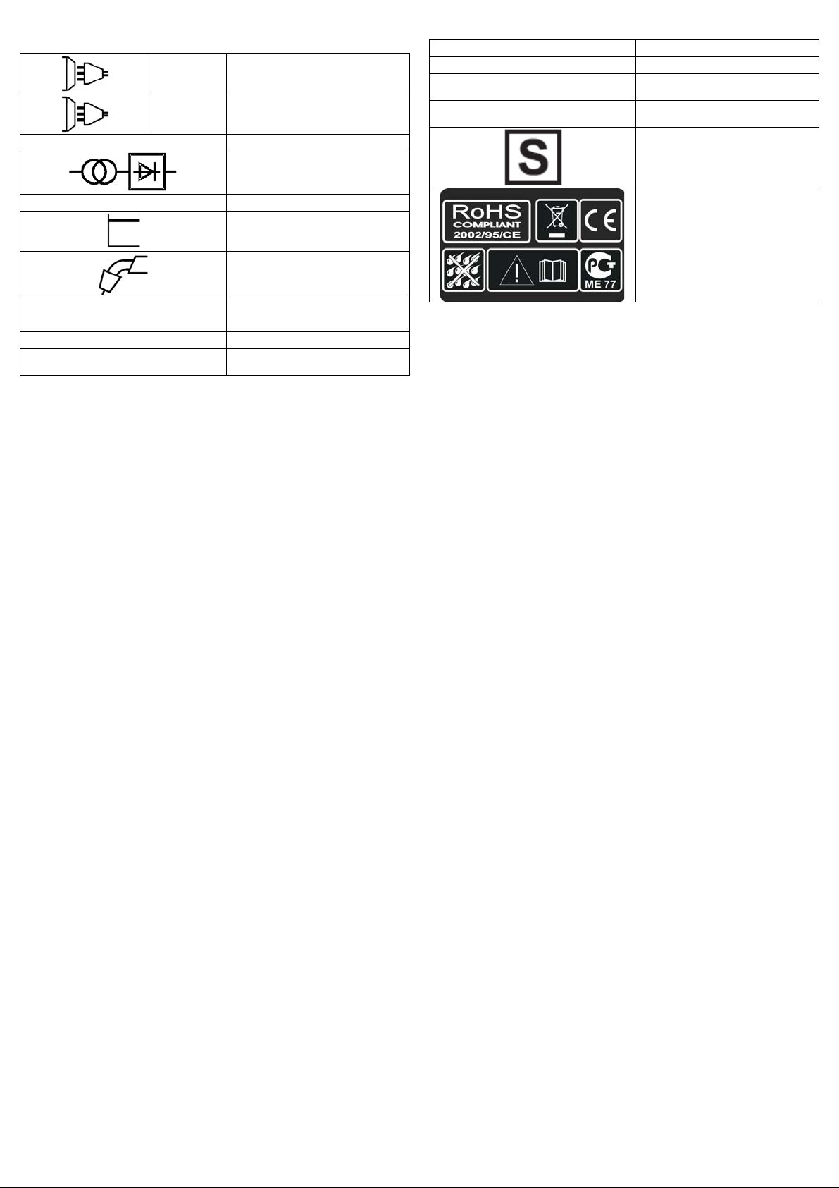
DESCRIPTION OF SIGNS AND SYMBOLS
f
1 ~
Single phase alternating voltage
3 ~
Three phase alternating voltage
U 0 … (V)
Nominal open circuit voltage
Transformer-rectifier
EN 60974-1
Norm of reference
I
1 ef
IP21
… (A)
X
H
Effective current supplied
Duty cycle
The welding unit's protection
class
The transformer's insulation
class.
Welding machine suitable for use
in environments with heightened
risk of elec tric shoc k.
U 1 … (V/Hz)
I 2 … (A)
I
(A)
1 max
FAULT
Wire isn’t conveyed when
Feed roll is turning
Wire feeding in jerk or
erratic way
No arc
Porous welding seams
The machine suddenly stops welding
operations after an extended and heavy
duty use
Flat characteristic
MIG-MAG wire feed welding
Nominal values of mains voltage
and frequency
Welding current
The welding unit's maximum
absorbed current
FAULT FINDING
REASON
1) Dirt in liner and/or contact tip
2) The frition brake in the hub
is too tightened
3) Faulty welding torch
1) Contact tip defect
2) Burns in contact tip
3) Dirt in feed roll groove
4) Feed roll’s groove worn
1) Bad concat between earth clamp
and workpiece
2) Short-circuit between contact tip
and gas shroud
1) Failre of gas shield owing to
spatters in gas shro
2) Wrong welding torch distance
and/or inclination from workpiece
3) Too small gas flux
4) Humid workpieces
5) Heavily rusted workpieces
1) Welding machine overheated due
to an excessive use in stated duty
cycle
Symbols referring to safety
regulations
Blow with compressed air, replace contact
tip
Loosen
Check sheating of torchès
wire guide
Replace
Replace
Clean
Replace
Tighten earth clamp and check connections
Clean, replace tip and/or shroud as
necessary
Clean gas shroud from spatters
The length of stick out wire from tip must
be 5 – 10mm. Inclination not less than 60
degrees in relation to woekpiece
Increase flux of welding gas
Dry with heat producer
Clean workpieces from rust
Don’t switch off the machine, let it cool
down for about 20/30 minutes
REMEDY

DEUTSCH
ALLGEMEINE BESCHREIBUNG
SCHUTZGASSCHW EIßANLAGEN FÜR DAS VESCHWEIßEN VON
FÜLLDRAHTOHNE GAS UND VON STAHL, EDELSTAHL UND
ALUMINIUM MIT SCHUTZGAS.
1. TECHNISCHE INFORMATIONEN BEZÜGLICH DER
SCHWEIßMASCHINE
Die Schweißmaschine wird mit dem Hauptschalter eingeschaltet (1).
Die Stärke des bereitgestellten Schweißstromes ist mit Hilfe zwei
Wechselschalter (2).
Die Drahtgeschwindigkeit reguliert man mittels einem Encoder (3). Drei
rote Leds zeigen die gängige Geschwindigkeit an (4).
Das Schweißgerät ist mit einer Thermoschutzeinrichtung ausgerüstet, die
den Schweißstromzufluß automatisch unterbricht, sobald eine höhere
Temperatur erreicht wird (5). In diesem Fall leuchtet ein gelbes Warnlicht
auf. Sobald die Temperatur wieder auf einen für den Betrieb geeigneten
Wert absinkt, schaltet das Warnlicht aus. Der Stromzufluß wird
automatisch wiederaufgenommen und das Schweißgerät ist wieder
betriebsbereit.
2. INSTALLATION
2.1. ELEKTRISCHE VERBINDUNGEN
Die Schweißmaschine hat ein eigenes bestimmtes Speisekabel, das lang
genug ist, um nicht verlängert werden zu müssen. Sofern jedoch eine
weitreichendere Verbindung benötigt wird, ist es unbedingt erforderlich ,
ein Verlängerungskabel zu benutzen, das dem der Schweißmaschine
gleich ist.
Bevor die Schweißmaschine an eine Steckdose angeschlossen wird,
muß überprüft werden, ob die Spannung der der Schweißmaschine
gleich ist und ob die Leistungsabgabe ausreichend für eine Vollast des
Gerätes ist. Außerdem ist es unbedingt nötig festzustellen, ob die
Speiseanlage mit einem ausreichenden Erdungssystem ausgestattet ist.
Zuführungspannung
Ist die Speisespannung 230 V.
2.2. VERBINDUNG AN DIE GASFLASCHE (BEI DEN MODELLEN WO
DAS VORGESEHEN IST)
Die Gasflasche muß in den entsprechenden Raum auf der Hinterseite
des Geräts gesetzt werden, oder bei den anderen Modellen, auf der
entsprechenden Plattform. Vergewissern Sie sich, daß sämtliche
Gasanschlüsse fest versiegelt sind.
Die 1kg Gasflasche (OPTIONAL) auf der Rückseite der Maschine in dem
vorgesehenen Gestell positionieren und mit dem beigelegten Gurt
anziehen (Fig.1). Falls die Maschine mit einer 5kg Gasflasche
ausgerüstet ist (Optional), muss man, nachdem der Räder - Satz montiert
wurde, die Gasflasche auf der Halterung positionieren und mit der Kette
anziehen. (Fig.2) Falls Sie das CO
einen Adapter brauchen. Fragen Sie Ihren Detailverkäufer.
gebrauchen, ist es möglich, dass Sie
2
eingeführt. Im Gegenteil wird es in den Ausgang des negativen Pols (-)
eingeführt für Gasschweissungen.
2.4. MONTAGE DES HANDGRIFFES
Den Handgriff montieren wie in Fig. ersichtlich, indem man die
beigelegten Schrauben verwendet.
2.5. MONTAGE DES RAEDERSATZES (OPTIONAL)
Einige Modelle sind mit einem Rädersatz ausgerüstet, welches folgendes
enthält: Stützfuß,
Schienenwagen, Achse, Flaschenhalter, Fixierketten, Traggriff, 2
Plastikräder und zwei
Blockadenstöpsel. Das folgende Schema für die Montage befolgen.
Fig. 1
Regler 1 kg. Regler 5 kg. Adapter CO2
2.3. ERDVERBINDUNG
Die Schweißmaschine wird schon mit einem geeigneten Erdungskabel,
das mit einer Zange verbunden ist, geliefert. Achten Sie darauf, daß die
Zange einen leistungsfähigen Kontakt mit dem zu schweißenden Teil hat.
Die Kontakte müssen von Schmierfett, Rost und Verschmutzungen
gereinigt und geschützt werden. Ein nicht leistungsfähiger Kontakt
vermindert die Schweißkapazität und somit wird das Ergebnis der
erfolgten Schweißung nicht perfekt sein. Das Ende der Erdzange wird im
Fall von Ohne-Gas Schweissung in den Ausgang des positiven Pols (+)
Fig. 2
3. EINBAU DER DRAHTSPULE UND DES SCHLAUCHPAKETS
3.1. EINBAU DER DRAHTSPULE
Die Maschinen können sowohl Spulen mit ø100 als auch ø200
montieren. Die Nabe ist voreingestellt, um den Draht immer steif zu
halten.
ø100
ø200
3.2. DRAHTVORSCHUBMOTOR
Versichern Sie sich, daß die Furche der Drahtvorschubspule den
gleichen Durchmesser des Drahtes hat. Auf der Seitenfläche der Spule
ist der zu gebrauchende Durchmesser gedruckt. Die Schweißgeräte sind
mit gerändelten Rollen versehen zum Fülldrahtschweissen ohne
Schutzgas. Zum Schweissen von festen Drähten, ersetzen Sie die Rolle
des Drahtvorschubmotors mit einer Rolle mit V förmigen Nuten für
Stahldraht und U förmigen Nuten für Aluminiumdraht. Fragen Sie ihr
Fachhandler oder die Herstellerfirma die entsprechenden Rollen und
Druckregler an, wenn Sie das Schweissgerät mit Schutzgas gebrauchen
wollen.
3.3. EINFÜHRUNG DES DRAHTES
1. Den Federarm auskuppeln (1) und gegen oben drehen (2), so dass es
vom Führungsrad entfernt wird (3). Sich vergewissern, dass der
Führungsrad der Drahtdurchmesser, das man gebraucht sichtlich signiert
ist.
2. Mit Vorsicht den Draht von der Drahtspule lösen. Um lästige
Abrollungen zu verhindern, bis zum Punkt (5) gespannt halten.
3. Die ersten 100 mm des Drahtes oder das ganze nicht total gerade Teil
abschneiden.
4. Den Draht in der Führung einfügen (4), über der Führungsrolle (3) und
dann in den Kapillarrohr einfügen (5).
5. Den Drahthalterarm schließen, indem man die Feder geladen hält. Die
Spule drehen, so dass der Draht noch mehr gelockert wird.
6. Den Drahtdruckregulierungsschalter ist auf Halbdruck reguliert. Im
Falle, dass der Druck zu hoch ist (Gefahr, dass der Draht abgeflacht
wird), den Schalter abschrauben, so dass der Druck vermindert wird. Ein
höherer Druck ist erfragt im Falle des Gebrauchs des Drahtes von 0,6
mm. Falls die Führungsrolle rutscht, muss man den Druck erhöhen bis
der Draht regelmäßig vorrückt.
7. Die Gasführungsdüse und die Kontaktspitze von der
Schweißbrennerpistole entfernen.
8. Den Schalter auf die Position „ON” einstellen. („I”)
9. Den Schweißbrennerkabel so ziehen, so dass er gerade ist.
10. Den Schweißbrennerdrücker drücken und den Draht alimentieren bis
dieser am Ende der Pistole erscheint ( Achtung: die Pistole nicht gegen
sich selbst oder andere Personen richten), dann den Drücker wieder
loslassen.
11. Die Maschine ausschalten, indem die Position „OFF” („O”) eingestellt
wird.
12. Die Kontaktspitze und die Gasdüse wiedereinsetzen.
13. Den Draht 6-10 mm über der Spitze abschneiden. Nun ist die
Maschine bereit für das Schweißen.
3.4. VERBINDUNG DES SCHLAUCHPAKETS
Ist das Schlauchpaket direkt verbunden und somit schon gebrauchsfähig.
Ein eventueller Austausch muß mit extremer Vorsicht, oder besser direkt
von einem Fachmann vorgenommen werden. Um die
Gasausgangsspitze auszutauschen ist es ausreichend, sie
abzuschrauben oder nach außen hin zu ziehen. Die Gasausgangsspitze
ist jedesmal rauszunehmen, wenn die Drahtvorschubdüse ausgetauscht
werden muß. Es ist zu beachten, daß der Durchmesser der Düse immer
dem des Drahtes gleich ist. Die Gasausgangsspitze muß ständig
saubergehalten werden.
4. SCHWEIßARTEN
4.1. DURCHGEHENDE SCHWEIßUNG
Dieses ist das verbreiteste Schweißsystem. Ist das Gerät einmal zum
Schweißen vorbereitet, reicht das Drücken der Lötgebläsetaste, um die
Schweißarbeiten verrichten zu können. Sind die Schweißarbeiten
beendet, ist es ausreichend die Schweißbrennertaste loszulassen.
4.2. GASDRUCK
Der Gasdruck muß so geregelt werden, daß die entsprechende
Versorgung zwischen 6 und 12 Litern liegt. Die Wahl des Gasdruckes ist
jedoch sehr individuell.
4.3. GAS - NO GAS SCHWEIßUNG
4.3.1. GAS - Die Klemme des Schweißbrenners mit dem positiven “+”
Auslaß und die Zange der Erdung mit dem negativen “-” Auslaß
verbinden.
4.3.2. NO GAS - Die Zange der Erdung in die positive “+” Verbindung
und die Klemme des Schweißbrenners in die negative “- “ Verbindung
einsetzen.
4.4. MIG - MAG SCHWEIßUNG
A) MIG = Metal Inert Gas
B) MAG = Metal Active Gas
Beide Vorgänge sind sich völlig gleich, nur der angewendete Gastyp
ändert.
Für den Punkt A) ist das gebrauchte Gas ARGON (Edelgas)
Für den Punkt B) ist das gebrauchte Gas CO
Um die Aluminium- oder Stahllote zu schweißen, ist es erforderlich reines
ARGON – Gas anzuwenden.
Das CO
verwendet werden.
5. SCHWEIßANLEITUNG
5.1. ALLGEMEINE REGEL
Bei einer Schweißung, die auf das Minimum gestellt ist, ist es wichtig
darauf zu achten, daß die Länge des Lichtbogens kurz ist. Dieses ergibt
sich sofern man den Schweißbrenner mit etwa 60 Grad Neigung so nah
wie möglich an den zu schweissenden Teil hält. Die Länge des
Lichtbogens kann verringert werden, indem man nach und nach die
Stromstärke erhöht. Dabei kann es auch zu einem Abstand von zirca
20mm kommen.
5.2. ALLGEMEINE RATSCHLÄGE
Von Zeit zu Zeit ist es durchaus möglich Mängel bei der Schweissung
festzustellen. Diese Mängel können jedoch vermieden werden, sofern die
folgenden Ratschläge beachtet werden:
· Porosität
Kleine Löcher in der Schweißnaht, ( ähnlich denen der Oberfläche der
Schokolade ) verursacht durch die Unterbrechung des Gasflusses oder
durch das Eindringen von kleinen Fremdkörpern. Das gebräuchlichste
Mittel ist das Schleifen und Wiederschweißen der Schweißarbeit. Bevor
die Schweißarbeit erneut ausgeführt wird, kontrollieren Sie, daß der
Gasfluß ( ca. 8l/min.) korrekt eingestellt ist und daß das Werkstück frei
vor Verschmutzungen ist . Darauf achten, daß der Schweißbrenner beim
Schweißen richtig geneigt wird.
· Bespritzung
Kleine, geschmolzene Metalltropfen , die vom Lichtbogen hervorgerufen
werden. In kleinen Mengen ist es unvermeidbar, aber es kann auf ein
Minimum reduziert werden, wenn der Strom - und Gasfluß genau
eingestellt werden und der Schweißbrenner immer saubergehalten wird.
· Schmale und abgerundete Schweißnaht
Die Ursache ist eine zu schnelle Führung des Schweißbrenners oder ein
nicht gut geregelter Gasfluß.
· Dicke und breite Schweissnaht
Die Ursache kann eine zu langsame Führung des Schweißbrenners sein.
· Drahtenende angebrannt
Kann durch ein zu langsamer Vorschub des Drahtes, durch gelockerte
oder abgenutzte Kabelführungsspitze, geringe Kabelqualität, durch eine
zu geschlossene Gasrohrspitze oder ein zu hoher Stromfluß verursacht
werden.
· Geringes Eindringen der Schweißnaht
Kann durch ein zu schnelles Führen des Schweißbrenners, eine zu
Gas allein kann nur bei Schweißungen von Kohlenstahl (Eisen)
2
(aktives Gas)
2
niedrige Stromspannung, ein nicht korrekt funktionierender
f
Drahtvorschub, durch umgekehrte Polarität, Abstumpfungen und
unzureichender Abstand zwischen den Limbus verursacht werden. Auf
die Einstellung der operativen Parameter achten und die Vorbereitung
der Werkstücke verbessern.
· Durchlöcherung des Werkstücks
Kann durch eine zu langsame Führung des Schweißbrenners, eine zu
hohe Stromspannung oder ein nicht funktionsgerechter Drahtvorschub
verursacht werden.
· Starke Bespritzung und Porosität
Kann durch eine übermäßige Distanz des Gasbrenners vom Werkstück
verursacht werden, Schmutz auf den Werkstücken oder ein zu knapper
Gasfluß. Der Gasfluß muß nicht geringer als 7-8 Liter/ min. sein und der
Schweißstrom muß dem benutzten Drahtdurchmesser entsprechen. Es
ist ratsam, einen Eingang- und Ausgangdruckregler zu haben. Auf dem
Ausgangsmanometer kann man auch die Fördermenge in Liter ablesen.
· Unbeständiger Lichtbogen
Die Ursachen sind eine unzureichende Stromspannung, unregelmäßiger
Drahtvorschub und nicht ausreichender Schutzgas.
BESCHREIBUNG DER ZEICHEN UND DER SYMBOLE
1 ~
Wechselspannung einphasig
EN 60974 - 1
U 1 … (V/Hz)
I 2 … (A)
I
… (A)
1 max
I
… (A)
1 ef
X
IP21
H
Norm des Hinweises
flache Eigenschaft
Drahtschweißung MIG - MAG
Dieses Symbol bedeutet nominale
Speisespannung und nominale
Frequenz der Leitung
Schweißstrom
Maximale Stromaufnahme der
Leitung
Tatsächliche Stromversorgung
Einschaltdauer
Schutzklasse des Schweißgerätes
Isolationsklasse des Trans-formators
Schweißmaschine geeignet zur
Benutzung in Umgebungen mit
erhöhter Stromschlaggefahr
3 ~
Wechselspannung dreiphasig
U 0 … (V)
Der Draht wird von der Drahtführungsrolle
nicht weitergeführt
Unregelmäßige Drahtführung
Der Lichtbogen erlischt
Poröse Schweißnaht
Das Gerät hört nach längerem Gebrauch
plötzlich auf zu funktionieren
ART
Maximale Leerlaufspannung
Gleichrichtertransformator
STÖRUNGSSUCHE
DER
1) Gasführungsdüse verschmutzt
oder Leitugsdraht an die
Gasführungsdüse geklebt.
Drahtrolle verschmutzt
2) Drahtrollenhalterung zu stark
gespannt
3) Schweißbrenner ist defekt
1) Kontaktdüse ist defekt
2) Brandspuren an der Kontaktdüse
3) Verschmutzung der Führungsrille
der Drahtführungsrolle
4) Führungsrille auf der
Drahtführungsrolle abgenutzt
1) Unzureichender Kontakt zwischen
Werkstück und Massekabel
2) Kurzschluß zwischen Kontaktdüse
und Gasführungsdüse
1) Schutzgasmangel hervorgerufen
durch Schmutz in der
Gasführungsdüse
2) Falscher Abstand oder
Neigungswinkel beim Führen des
Schweißbrenners
3) Geringer Gasfluß
4) Feuchte Werkstücke
5) Stark verrostete Werkstücke
Das Gerät wurde durch zu langen Gebrauch
überhitzt und durch den Thermoschutz
automatisch abgeschaltet
Symbole mit Bezug auf
Sicherheitsnormen
STÖRUNG
Drahtrolle mit Druckluft reinigen Gasführungsdüse
austauschen
Befestigungsrädchen etwas lösen
Drahtführung kontrollieren
auswechseln
auswechseln
reinigen
auswechseln
Kontakt zwischen Massekabel und Werkstück
überprüfen und verbessern
Kontaktdüse und Gasführungsdüse reinigen oder
austauschen
Reinigen oder auswechsein
Der Abstand zwischen Schweißbrenner und
Werkstückl iegt zwischen 5 – 10 mm. Der
N
eigungswinkel zum Werkstück sollte nicht weniger
als 60° sein
Gasfluß erhöhen
Mit Warmluftpistole trocknen
Werkstücke vorn Rost befreien
Das Gerät etwa 20 – 30 min abkühlen lassen
 Loading...