


ITALIANO
DESCRIZIONE GENERALE
Le saldatrici ad arco sono saldatrici monofase a corrente alternata
230V 50/60Hz oppure 230/400V 50/60 Hz. Esse hanno una struttura
robusta e compatta che le rendono affidabili e versatili sotto ogni
condizione di carico. Il rispetto delle norme e l’ottima qualità dei
materiali, che le costituiscono, garantiscono una lunga durata in
piena sicurezza.
SIGNIFICATO DELLE SCRITTE E DEI SIMBOLI
Trasformatore monofase
Caratteristica cadente
EN 60974-1
EN 60974-6
1 ~
Norme di riferimento
Alimentazione monofase
3 ~
Alimentazione trifase
U 0 … (V)
U 1 … (V/Hz)
I 2 … (A)
Ø (mm)
t w
t
r
I
(A)
1 max
IP21
H
INSTALLAZIONE
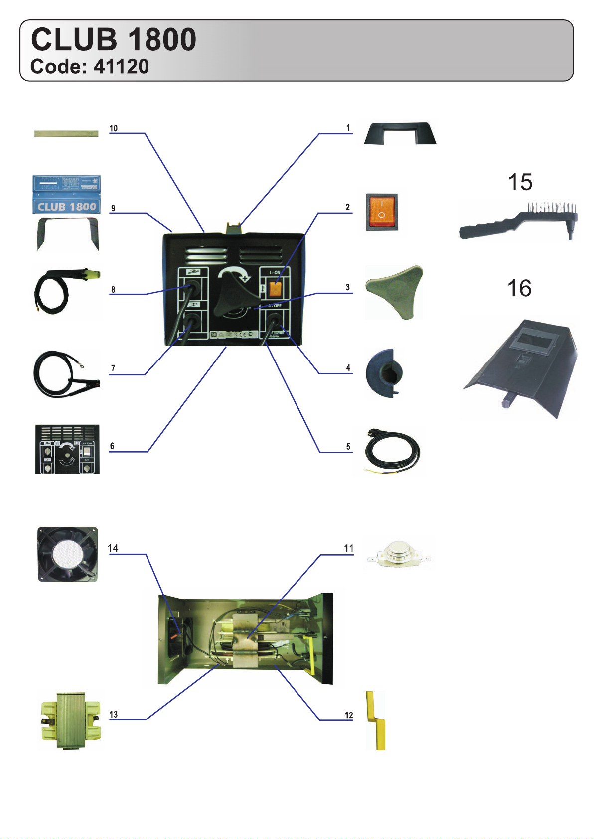
Disimballare e montare le parti staccate della saldatrice.
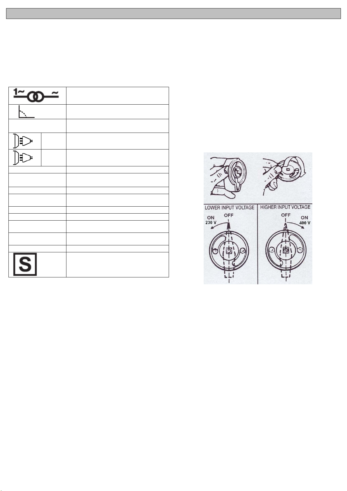
Per i modelli a due tensioni ruotare il commutatore sulla tensione
desiderata dopo aver spostato il fermo.
INFORMAZIONI TECNICHE SULLA SALDATRICE
La saldatrice è dotata di un dispositivo di protezione termica che
interrompe automaticamente l’erogazione della corrente per la
saldatura, in tal caso si accende una spia luminosa gialla. Quando la
temperatura interna diminuisce e ritorna ad un valore opportuno per
un corretto funzionamento, la saldatrice entrerà automaticamente in
funzione.
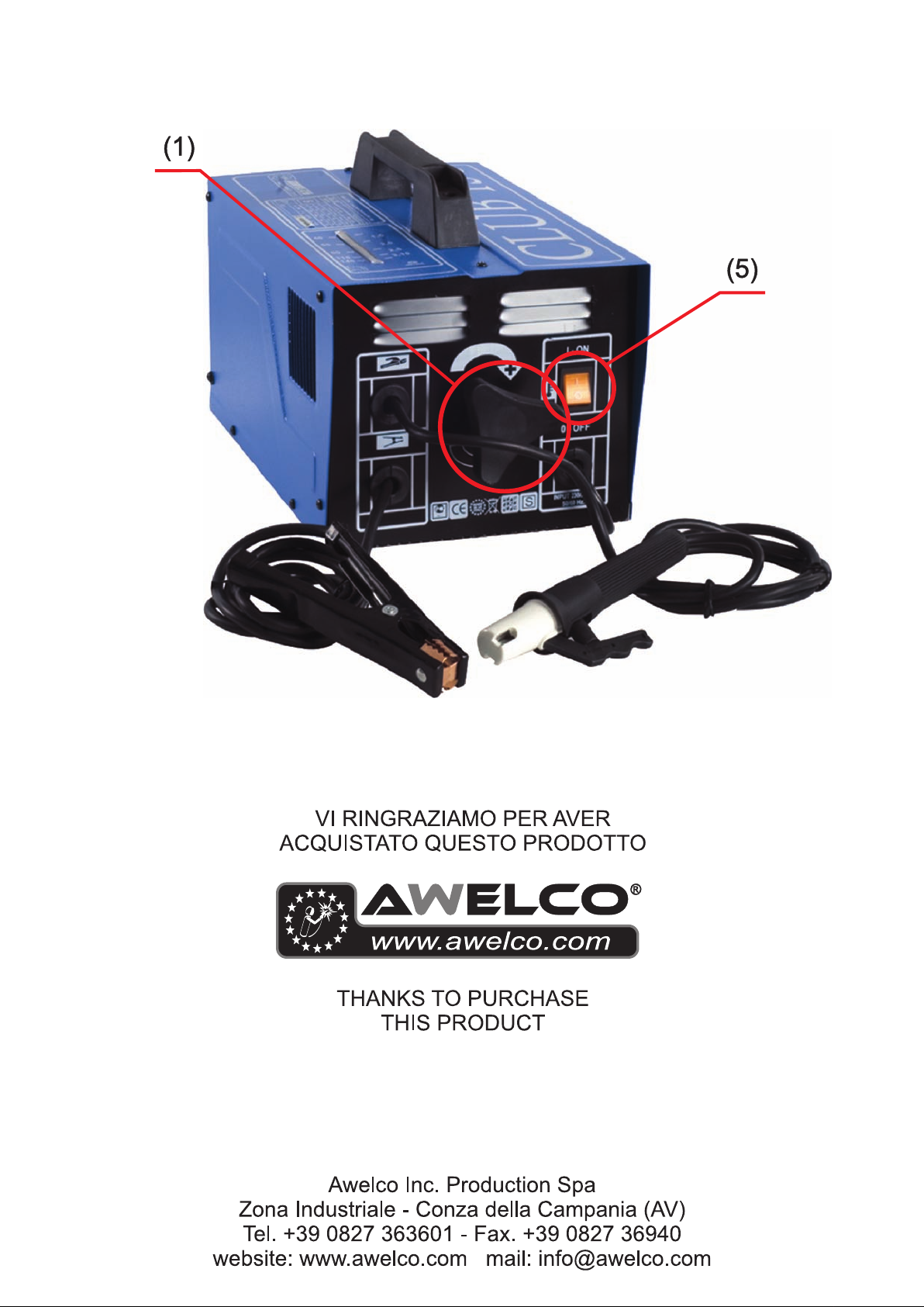
Per mettere in funzione la saldatrice agire sull’interruttore generale.
L’intensità della corrente di saldatura erogata è regolabile per mezzo
di un deviatore azionabile manualmente oppure con continuità
mediante un volantino.
La regolazione va fatta tenendo conto dei valori di corrente di
saldatura in funzione del diametro dell’elettrodo.
ALCUNE INFORMAZIONI UTILI PER SALDARE
La zona di saldatura deve essere priva di ruggine e vernice. Secondo
il tipo di materiale si sceglie il tipo di elettrodo. Consigliamo di
Valore nominale della tensione di
uscita a vuoto
Valore nominale della tensione di
alimentazione e della frequenza
Corrente di saldatura
Diametro elettrodo saldabile
Intervallo di tempo tra l’operazione di
riarmo e quella di intervento del
dispositivo termico di interruzione
Intervallo di tempo tra l’operazione di
intervento e quella di riarmo del
dispositivo termico di interruzione
Corrente massima assorbita
Grado di protezione della saldatrice
Classe di isolamento del trasformatore
Saldatrice adatta all’uso in un
ambiente con rischio accresciuto di
scosse elettriche
controllare inizialmente l’elettrodo e la sua intensità di corrente
provando su un particolare di scarto. Piazzate l’elettrodo a una
distanza di 2 cm ca. sopra il punto di partenza e munitevi di schermo
protettivo. Toccate leggermente strisciando con l’elettrodo il
particolare finchè avvenga l’accensione dell’arco voltaico. Attraverso
lo schermo protettivo osservate l’arco, la cui lunghezza dovrà
corrispondere 1-1.5 volte il diametro dell’elettrodo.
Il saldatore deve cercare di mantenere costante la lunghezza
dell’arco. Siccome l’elettrodo si consuma bisogna avvicinarsi
costantemente.
Al termine del cordone di saldatura, portare l’estremità dell’elettrodo
leggermente indietro rispetto alla direzione di avanzamento per
evitare la formazione di un cratere poroso.
La scoria non deve essere allontanata prima che il cordone si sia
raffreddato. La saldatura di un cordone interrotto viene ripresa dopo
aver tolto la scoria al punto di partenza.
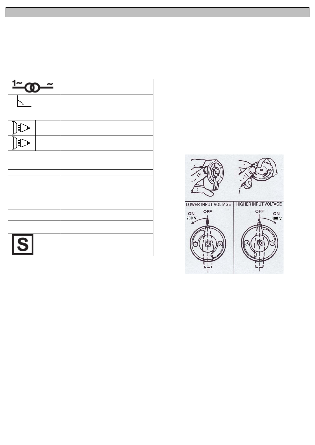
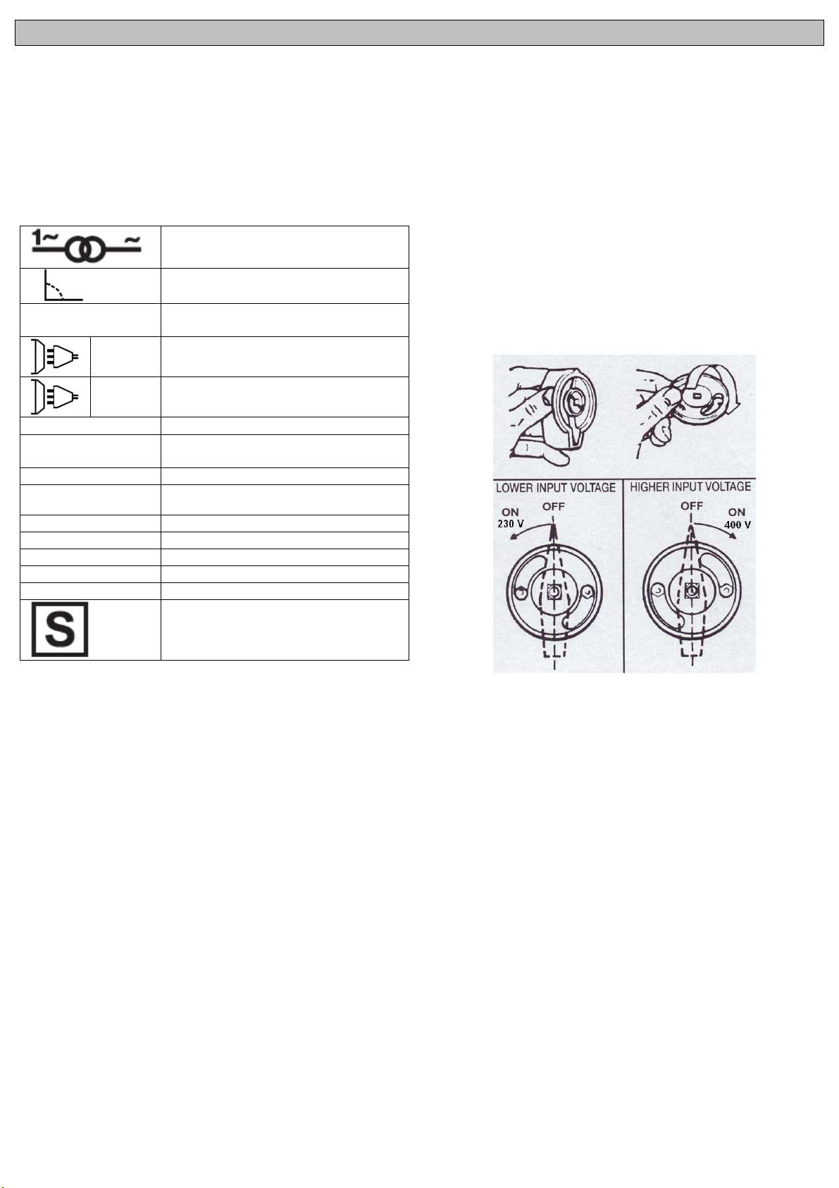
SELEZIONE 230/400V
Per poter selezionare il cambio tensione sulla saldatrice è sufficiente
girare l’interruttore munito di camma che a seconda della posizione
permette di orientare il pulsante verso 230V o 400V.
ISTRUZIONI PER IL MONTAGGIO DELLE RUOTE E DELLA
MANIGLIA
(PER I MODELLI PREDISPOSTI)
MANIGLIA:
Le viti sono già fissate sulla carrozzeria e di conseguenza:
1) Svitare le viti parker e posizionare la maniglia in modo che i fori.
2) Riavvitare le viti e serrare ben forte.
PROLUNGA MANIGLIA
1) Infilare il tubo nell’apposito spazio della maniglia e spingere bene
a fondo.
2) Fissare con la vite appropriata il tubo alla maniglia in plastica.
SUPPORTO ANTERIORE
Le viti sono già fissate sul fondo della carrozzeria e di conseguenza:
1) Svitare le viti parker e posizionare il supporto anteriore in modo
che i fori
corrispondano.
2) Riavvitare le viti e serrare ben forte.
RUOTE
1) Introdurre l’asse negli appositi fori
2) Infilare le ruote sull’asse.
3) Le coppiglie servono a bloccare le ruote sull’asse.
ENGLISH
GENERAL DESCRIPTION
The models are portables single-phase AC arc welder 230V-50/60
Hz or 230/400V- 50/60 Hz.
Their compact and robust formats make them versatiles and
efficients for a variety of uses. Its compliance to current regulations
and the optimum quality of materials used, will ensure a long working
life in complete safety.
DESCRIPTION OF SIGNS AND SYMBOLS
Single-phase transformer
Falling characteristic
EN 60974-1
EN 60974-6
1 ~
3 ~
U 0 … (V)
U 1 … (V/Hz)
I 2 … (A)
Ø (mm)
t w
t
r
I
1 max
IP21
H
INSTALLATION
Unpack the welding machine, assemble the separate parts contained
in the package.
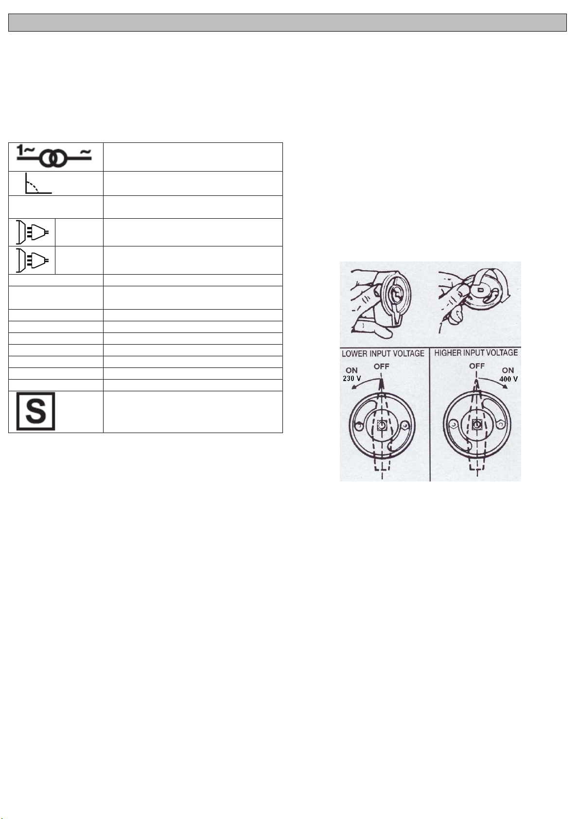
For welders with double voltage supply, it is necessary to set the
blocking screw of the voltage-reverse switch in the position
corresponding to the voltage really available. To use a thorn chosen
on the base of the value of the fuse indicated on the plate.
TECHNICAL INFORMATION
The welder is fitted with a thermal overload cut-out which operates
automatically to stop the transformer overheating.
The machine will become operational again automatically once the
temperature has reduced itself to an acceptable working level.
To switch on the welding machine operate the main switch. The
intensity of the supplied welding current can be adjusted by means of
a manually operated switch or using the hand wheel.
The welding current must be regulated according to the diameter of
the electrode in use and the type of the joint to be carried out: see
below the currents corresponding to various electrode diameters.
WELDING HINTS
The welding surface should be free of rust or paint. Choose the
electrode in accordance with the material being welded. It is
adviseable to initially test electrode and amperage on some scrap
(A)
Norms of reference
Single phase alternating voltage
Three phase alternating voltage
Nominal open circuit voltage
Nominal values of mains voltage and
frequency
Welding current
The diameter of the electrodes which can
be welded
Time between the reset and the set of
the thermal cut-out device
Time between the set and the reset of
the thermal cut-out device
The welding unit's maximum absorbed
current
The welding unit's protection class
The transformer's insulation class.
Welding machine suitable for use in
environments with heightened risk of
electric shock.
material.
Place the electrode at a distance of 2 cm. from the workpiece and
place the face shield in position to protect the eyes. Strike the arc by
bringing the electrode into contact with the workpiece with a light
tapping and scrapping action.
Through the face shield you will see the arc which should be in
length one to one and a half the diameter of the electrode.
It is important to maintain a constant length of the arc. As the
electrode melts and its length decreases, a gradual downward
movement is needed to maintain the correct distance and the arc
itself.
To stop welding simply withdraw the electrode away from the
workpiece. It is adviseable to lift into the weld seam to avoid a porous
crater.
Be careful - the metal and electrode tip will be hot. Remove the
surface slag when cooled by lightly tapping with a pointed tool.
Welding may be resumed from the same spot having first ensured
the removal of the slag.
HOW TO SELECT 230/400V
To change the voltage its sufficient to unscrew the knob of the
commutator. Back of it there is a plastic cam. According to the
position it permit to turn the knob toward the 230V or 400V.
INSTRUCTIONS FOR HANDLES AND WHEELS ASSEMBLING
(JUST FOR THE MODELS EQUIPED WITH )
HANDLE
The screws are already screwed on the body, therefore:
1) Unscrew the parker screws and place the handle in order to make
the holes correspond.
2) Screws the screws again tightening strongly.
EXTENDED HANDLE
1) Insert the handle in the proper space of the handle pushing to the
bottom.
2) Screws with the proper screw the tube to the plastic handle.
FRONT SUPPORT
The screws are already screwed on the bottom of the body,
therefore:
1) Unscrew the parker screws and place the plate front support in
order to make the holes correspond.
2) Screws the screws again tightening strongly.
WHEELS
1) The axe is to be introduced in the proer space.
2) Insert the wheels on the axe.
3) The plugs are used in order to block the wheels on the axe.
DEUTSCH
r
ALLGEMEINE BESCHREIBUNG
Die Tragbäre Lichtbogenschweißapparäte, einphasiger
Schweißapparäte mit Wechselstrom 230V/50Hz oder 230/400V
50/60HZ. Ihr kräftiger und kompakter Bau macht sie, ganz gleich
unter welchen Belastungsbedingungen, zu cinem stabilen und
zuverlässigen Werkzeug. Die Einhaltung der Normen und die
ausgezeichnete Qualität des Materials, aus dem sie besteht,
garantieren eine lange, sichere Dauer.
BEDEUTUNG DER AUFSCHRIFTEN UND DER SYMBOLE
Einphasentrafo
Fallende Eigenschaft
EN 60974-1
Norm des Hinweises
EN 60974-6
Wechselspannung einphasig
1 ~
Wechselspannung dreiphasig
und die Stromstärke an einem Abfallstück auszuprobieren. Setzen
Sie die Elektroden in cinem Abstand von ca. 2 cm. über dem
Ausganspunkt an nachdem Sie sicht mit cinem Schutzschirm
versehen haben.. Berühren Sie das Stück leicht streifend mit der
Elektrode.
Der Schweißer sollte versuchen, die Bogenlänge konstant zu halten.
Da sich die Elektroden abnutzen, muß man sich laufend nähern. Am
Ende der Schweißnaht empfielt es sich die Elektrode in Richtung
Naht zu entfernen, um die Bildung cines porösen Kraters zu
vermeiden.
Die Schlacke darf nich entfernt werden bevor der Rad der
Schweißnacht ausgekühlt ist. Das Schweißen einer unterbrochenen
Naht wirdnach der Schlackenentfernung wieder aufgenommen.
WIE 230/400V USZWAHLEN SIND
Um die spannung zu verandern sein genugend, den Knauf von
abzuschrauben das Umwandlung, Rucken davon es gibt einen
plastichen Nocken. Der Position zufolge es Genehmigung, den Knauf
zu den 230V oder 400V biphase zu drehen.
3 ~
U 0 … (V)
U 1 … (V/Hz)
I 2 … (A)
Ø (mm)
t w
t
I
(A)
1 max
IP21
H
INSTALLATION
Die Schweißmaschine von der Verpackung befreien, die lose
gelieferten Teile sind zu montieren.
Bei Schweissgeräte mit zwei Spannungen, stellen Sie die
Blockierschraube des Spannungswahlschalter in der Stellung
entsprechend der realen verfügbaren Spannung.
TECHNISCHE INFORMATIONEN BEZÜGLICH DER
SCHWEIßMASCHINE
Die Schweißmaschiene ist mit einer Wärmeschutzvorrichtung
ausgestattet, welche die Stromversogung für das Schweißverfahren
automatisch unterbricht, in diesem Falle leuchtet eine gelbe
Signallampe auf. Sobald die Innetemperatur wieder auf einen für den
korrekten Betrieb passenden Wert gesunken ist, läuft der
Schweißapparat automatisch wieder an.
Die Schweißmaschine wird mit dem Hauptschalter eingeschaltet. Die
Stärke des bereitgestellten Schweißstromes ist mit Hilfe eines
handbetätigten Wechselschalter läßt er sich stufenweise regeln oder
mit Hilfe des Handrades.
Die Korrektheit der Regulierung kann mit dem sich auf der Maschine
befindlichen Spannunganzeiger geprüft werden. Auf jeden Fall muss
der Benutzer die Position des Cursors entsprechend Empfindlichkeit
richtig wählen.
EINIGE NÜTZLICHE INFORMATIONEN ZUM SCHWEIßEN
Die Schweißzone soll rost-und lackfrei sein. Die Elektrode wird je
nach Art des Materials gewählt. Wir empfehlen anfangs die Elektrode
Maximale Leerlaufspannung
Dieses Symbol bedeutet Nennspeise-
spannung und Nennfrequenzder Leitung
Schweißstrom
Den Durchmesser der Elek-trode, mit der
geschweißt werden kann
Ist die Ladezeit für jeden Zyklus
Ist die Nachstellzeit für jeden Zyklus
Maximale Stromaufnahme der Leitung
Schutzklasse desSchweißgerätes
Isolationsklasse des Trans-formators.
Schweißmaschine geeignet zur
Benutzung in Umgebungen mit
erhöhter Stromschlaggefahr
MONTAGEANWEISUNGEN FÜR DIE BEFESTIGUNG VON GRIFF
UND RÄDERN
(BEI DEN MODELLEN, DIE DAMIT AUSGERÜSTET SIND)
HANDGRIFF
Die Schrauben werden bereits auf den Körper, deshalb geschraubt:
1) Schrauben Sie die parker Schrauben ab und setzen Sie den Griff,
um die Löcher entsprechen zu lassen.
2) Schraubt die Schrauben, die wieder stark festziehen.
AUSGEDEHNTER GRIFF
1) Stecken Sie die Griffverlängerungsstange in die dafür
vorgesehene Öffnung im Plastikgriff.
2) Befestigen Sie die Griffverlängerungsstange mit einer geeigneten
Schraube an den Plastikgriff.
STANDFUSS
Die Befestigungsschrauben sind schon am Gehäuseboden befestigt:
1) Lösen Sie die Befestigungsschrauben und legen Sie den Standfuß
so an die Bohrung an, daß diese mit den Befestigungslöcher im
Standfuß übereinstimmt.
2) Befestigen Sie den Standfuß mit den Befestigungsschrauben.
RÄDER
1) Steken Sie die Radachse in die dafür vorgesehene Bohrung an
der Hinterseite
des Gehäuses.
2) Setzen Sie die Räder auf die Achse.
3) Sie die Räder auf die Achse mit Hilfe des Plastikpfropfens.
FRANÇAIS
r
DESCRIPTION GENERALE
Les postes à souder, sont des postes monophasé à courant alternatif
230V 50/60 Hz où bien 230/400V 50/60 Hz. Ils ont une structure
robuste et compacte qui rend les appareils fiables et versatiles quel
que soit la condition de charge. Le respect des normes et la bonne
qualité des matériels dont ils sont construits, garantissent une vie
prolongée en plein sécurité.
LEGENDE DES SYMBOLES
Transformateur monophasé
Caractéristique en baisse
EN 60974-1
Norme de la référence
EN 60974-6
Tension alternative monophasée
1 ~
Tension alternative triphasée
3 ~
U 0 … (V)
U 1 … (V/Hz)
I 2 … (A)
Ø (mm)
t w
t
I
(A)
1 max
IP21
H
INSTALLATION
Déballer la machine et procéder au montage des parties contenues.
Pour les postes de soudage munis de double tension d’alimentacion
régler la vis de blocage de la poignée du commutateur changement
de tension sur la position correspondante à la tension de ligne
effectivement disponible.
INFORMATIONS TECHNIQUES DU POSTE A SOUDER
Le poste est conçu avec un dispositif de protection thermique qui
interrompt automatiquement l’érogation du courant pour la soudure,
dans ce cas une lampe témoin jaune s’allume. Lorsque la
température interne diminue et se stabilise à la valeur adéquate pour
un fonctionnement correct, le poste se remettera en fonction
automatiquement.
Allumer le poste de soudage au moyen de l'interrupteur général.
L'intensité du courant de soudage distribué peut être réglé avec
continuité au moyen d'un déviateur actionnable manuellement ou à
l´aidedu bouton manuel.
La régulation doit être effectuée selon les valeurs du courant de
soudure en fonction du diamètre de l’électrode. Il est sourtout la
qualité de l’électrode et la sensibilité du soudeur à établir le réglage
du courant.
QUELQUES INFORMATIONS UTILES POUR SOUDER
Où on doit souder doit être nettoyé de la vuille et vernis. Selon le
type du materiel il faut choisir l’electrode. Nous vous consillons
Tension maximale à vide
Tension alternative et fréquence
d'alimentation du poste de soudage
Le courant de soudage
Le diamètre de l´électrodequi est
destinée au soudage
Est le temps de l´introduction du cycle
Est le temps de la réinitialisation du cycle
Courant maximalconsommé de
l´équipement de soudage
La classe de protection del´équipement
de soudage
La classe d´isolement du transfor-mateur
Poste de soudage conçu pour utilisation
dans un milieu comportant des risques
importants de chocs électriques.
d’essaijer l’electrode en soudant sur un piece de metal ecorté.
Placez-vous l’electrode à une distance de 2 cm du point de depart et
utilisez une masque cagoule de protection. Touché avec l’electrode
la piece que vous devez souder juste pour allumer l’arc. Pendant la
pasque regardez l’arc dont la longuer doit être 1-1,5 fois le diametre
de l’electrode.
Le soudeur doit chercher de maintenir la longueur de l’arc constante.
Étant donné que l’électrode se consume, il faut se rapprocher
contamment. Au bout du cordon de soudure, il est conseillé
d’éloigner l’électrode en direction du cordon afin d’éviter un cratère
poreux.
La scorie métallique ne doit pas être enlevée avant que le cordon de
soudure se soit refroidi. Le soudage d’un cordon interrompu doit être
repris après avoir enlevé la scorie au point de départ.
SELECTION 230/400
Pour pouvoir sélectionner le choix de la tension sur le poste à souder
il suffit de dévisser le bouton de l’interrupteur, à l’arrière se trouve
une came, selon sa position permet d’orienter le bouton vers 230V
ou 400V.
INSTRUCTIONS POUR LE MONTAGE DE LA POIGNEE ET DES
ROUES
(SI LE MODÈLE EST ÉQUIPÉ AVEC)
POIGNÉE
Les vis du type sont dejà vissées sue la carrosserie et par
consequent:
1) Dévissez les vis de parker et placez la poignée afin de faire les
trous correspondre.
2) Revisser les vis en serrant bien fort.
POIGNÉE PROLONGÉE
1) Enfiler le tube dans l’espace approprié de la poignée, en poussant
à fond.
2) Visser avec la vis appropriée le tube à la poignée en plastique.
SUPPORT ANTERIEUR :
Les vis du type sont dejà vissées sue le fond de la carrosserie et par
conséquent:
1) Dévisser les vis parker et placer le support antérieur en tôle de
façon à ceque les trous correspondent.
2) Revisser les vis en serrant bien fort.
ROUES :
1) Introduire l’axe dans les trous appropriés.
2) Ajouter les roues à l’axe.
3) Les bouchons servent à bloquer la roue sur l’axe.

ESPAÑOL
DESCRIPCIONES GENERALES
Los grupos de soldar a arco portátiles, son soldadoras monofasIcas
a corriente alterna 230V,50/60 Hz y 230/400V 50/60/Hz. Sus
estructuras robusta y compacta les rinde confiable y versátil bajo
cada condición de carga. El respeto de las normas y la optima
calidad de los materiales, que la constituyen, garantizan una larga
duración en plena seguridad.
SIGNIFICADO DE LOS ESCRITOS Y DE LOS SIMBOLOS
Transformadormonofásico
Característica descendente
EN 60974-1
Norma de la referencia
EN 60974-6
Tensión alterna monofásica
1 ~
Tensión alterna trifásica
3 ~
U 0 … (V)
U 1 … (V/Hz)
I 2 … (A)
Ø (mm)
t w
t
r
I
(A)
1 max
IP21
H
INSTALACIÓN
Desembalar la soldadora, efectuar el montaje de las partes que
están separadas, contenidas en el embalaje.
Para las soldadoras abastecidas en doble tensión de alimentación,
hay que predisponer el tornillo de bloqueo del conmutador de
cambio-tension en la posición correspondiente a la tensión de
alimentación real.
INFORMACIONES TECNICAS SOBRE EL GRUPO DE SOLDAR
El grupo de soldar es dotado de un dispositivo de protección térmica
que interrumpe automáticamente la erogación de la corriente para la
soldadura, en tal caso se enciende una espia luminosa amarilla.
Cuando la temperatura interna disminuye y regresa a un valor
oportuno para un correcto funzionamiento, el grupo de soldar entrará
automáticamente en función.
Para encender la soldadora usar el interruptor general. La intensidad
de la corriente de soldadura distribuida se puede regular
continuamente por medio de un desviador que se acciona
manualmente o mediante el volante.
La regulación va hecha teniendo en cuenta los valores de corriente
de soldadura en función de los diámetros de los electrodos. En cada
caso es el usuario que debe elegir la mejor posciòn en fonccon de la
qualidad del electrodo y de su sensibilidad.
Tensión máxima en vacío
Tensión alterna y frecuencia de
alimentación de la soldadora
Corriente de soldadura
Diámetro de los electrodes admisibles
Es el tiempo de introducción de cada
ciclo
Es el tiempo de reiniciación de cada
ciclo
Corriente máxima absorbida por la
soldado-ra
Sigla que define el grado de protección
del aparato
Clase de aislamiento del transformador.
Soldadora adecuada para su uso en
ambiente con riesgo aumentado de
descargas eléctricas
UNAS INFORMACIONES UTILES PARA SOLDAR
La zona de soldadura tiene que estar privado de oxido y barniz.
Según el tipo de material se escoje el tipo de electrodo.
Aconsejamos de controlar inicialmente el electrodo y su intensidad
de corriente provando sobre un particular de desecho. Colocar el
electrodo a una distancia de 2 cm. ca sobre el punto de partida y
ponerse la mascara protectora. Toquen ligeramente arrastrando con
el electrodo el particular hasta que comience el encendido del arco
voltaico. Atravéz de la mascara protectora observe el arco, el cual
largo debe corresponder 1 - 1,5 veces el diametro del electrodo.
El soldador tiene que lograr de mantener constante el largo del arco.
Dado que el electrodo se gasta hay que acercorse constantemente.
Al termino del cordón de soldadura es aconsejable olejar el electrodo
en dirección del cordón para evitar un crater poroso.
La escoria no tiene que ser adejada antes que el cordón se haya
enfriado. La soldadura de un cordón interrumpido viene continuado
dispúes de haber quitado la escoria al punto de partida.
SELECCION 230/400V (Por los modelos que lo tienen
disponible)
Para seleccionar el voltage de entrada es preciso destornillar el
mango de el commutator. Detras de ello se encuentra un excentrico
en plastico. Segun la posicion permite de orientear el mango hacia el
230V o 400V.
INSTRUCCIONES PARA EL MONTAJE DE LA MANETA Y DE
LAS RUEDAS
(PARA LOS MODELOS QUE LO PREVEEN)
MANIJA
Los tornillos se atornillan ya en el cuerpo, por lo tanto:
1) Desatornillen los tornillos del parker y coloquen la manija para
hacer que los agujeros corresponden.
2) Enrescar los tornillo apretandolos con fuerza.
MANIJA EXTENDIDA
1) Enfilar el tubo en el sitio adeguado de la maneta empujando hasta
el fondo.
2) Rescar con su tornillo el tubo ala maneta de plastico.
SOPORTE
Los tornillo tipo estàn ya sujetos en el fondo del chasis, per lo tanto:
1) Desenrescar los tornillo parker y posicionar el soporte de chapa
haciendo de manera que los agujeros correspondan.
2) Enrescar los tornillo apretandolos con fuerza.
RUEDAS
1) El eje se debe introducir en el proprio alojamiento.
2) Las ruedas se deban introducir en el eje.
3) Los tapones sirven para bloquer las ruedas en el eje.
PORTUGUÊSE
r
DESCRIÇÃO GERAL
As máquinas de soldar da série, são monofásicas de corrente alterna
230V 50/60Hz ou 230/400 V 50/60 Hz.
Apresentam uma estrutura robusta e compacta que determina uma
fiabilidade e versatilidade sob qualquer condição de carga. A
observância das normas e a óptima qualidade dos materiais,
garantem uma longa duração e segurança.
LEGENDA DOS SÍMBOLOS
Transfor-mador monofásico
Caraterística de queda
EN 60974-1
Norma da referência
EN 60974-6
Tensão alternada monofásica
1 ~
Tensão alternada trifásica
3 ~
U 0 … (V)
U 1 … (V/Hz)
I 2 … (A)
Ø (mm)
t w
t
I
(A)
1 max
IP21
H
INSTALAÇÃO
Desembalar a máquina de solda, efetuar a montagem das partes
separadas, contidas na embalagem.
Para soldadores com fonte dobro da tensão, é necessário ajustar o
parafuso de obstrução do interruptor tensão-reverso na posição que
corresponde à tensão realmente disponível.
INFORMAÇÕES TÉCNICAS DA MÁQUINA DE SOLDAR
A máquina é dotada de um dispositivo de protecção térmica que
interrompe automaticamente a distribuição de corrente para a
soldadura, neste caso acende-se uma lâmpada de aviso amarela.
Quando a temperatura interna diminui e retorna a valores adequados
para um funcionamento correcto, a máquina retomará
automáticamente o funcionamento.
Para ligar a máquina de solda agir na chave geral. A intensidade da
corrente de soldagem distribuída é regulável com continuidade por
meio de um desviador com acionamento manual ou medianteo
botão.
A corrente de soldagem deve ser regulada em função do diâmetro do
eléctrodo utilizado e ao tipo de junção que se deseje efetuar. Em
todo o caso, é o utilizador que deve escolher correctamente a
posição do cursor em função da sua sensibilidade.
ALGUMAS INFORMAÇÕES ÚTEIS PARA SOLDAR
A zona de soldadura deve estar limpa de ferrugens e tintas. Segundo
o tipo de material escolhe-se o tipo de eléctrodo. Aconselhamos um
Tensão máxima em vazio
Tensão alternada e freqüência de
alimentação da máquina de solda
Corrente de soldadura
DIâmtero de eléctrodossoldáveis
É tempo de carga para cada ciclo
É tempo de reset para cada ciclo
Corrente máximaabsorvida pelo gerador
Grau de protecção doaparelho
Classe de isolamento do transformador
Máquina de solda apropriada para o uso
em ambiente com risco acrescido de
choques elétricos
ensaio inicial ao eléctrodo sobre uma peça de metal. Posicionar o
eléctrodo a uma distância de 2 cm do ponto de partida e utilizar uma
máscara de protecção. Tocar ligeiramente com o eléctrodo na peça
a soldar para formar o arco. Através da máscara de protecção
observar o arco, cujo comprimento deverá corresponder a 1-1,5
vezes o diâmetro do eléctrodo.
O soldador deverá procurar manter o comprimento do arco
constante. Visto que o eléctrodo se consome, é necessário uma
constante aproximação. No final do cordão de soldadura é
aconselhável afastar o eléctrodo em direcção do cordão para evitar
uma cratera porosa.
A escória metálica não deve ser afastada antes do arrefecimento do
cordão. A soldadura de um cordão interrompido deverá recomeçar
depois de se retirar a escória no ponto de partida.
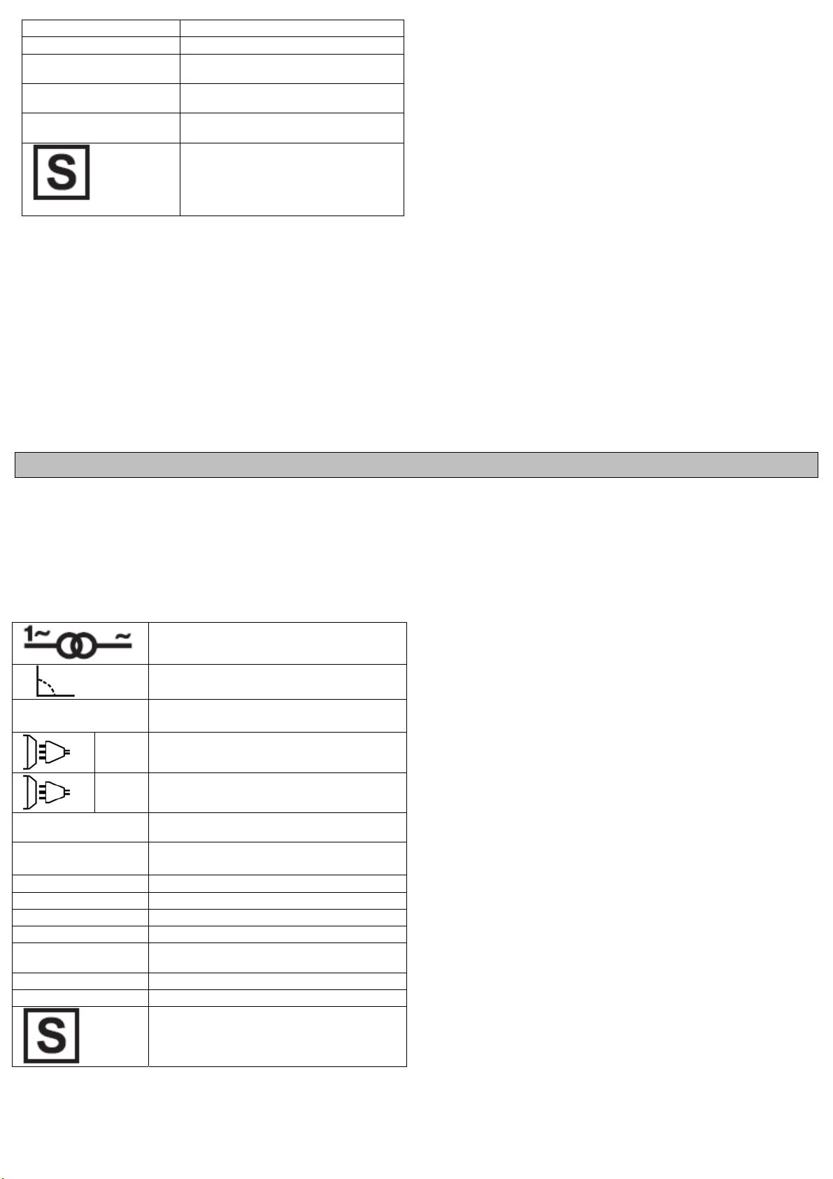
SELECÇÃO 230 / 400
Para se seleccionar a tensão da máquina de soldar basta girar o
botão do interruptor munido de came, que segundo a sua posição
permite orientar o botão para 230V mono ou 400V bifásico.
INSTRUÇÕES PARA A MONTAGEM DAS RODAS E DA PEGA
(PARA OS MODELOS PREDISPOSTOS)
PEGA
Os parafusos são parafusados já no corpo, conseqüentemente:
1) Desaparafuse os parafusos do parker e coloc o punho a fim fazer
os furos corresponder.
2) Apertar bem os parafusos.
PEGA PROLONGADO
1) Inserir o tubo no espaço apropriado da pega.
2) Aparafusar com o parafuso o tubo à pega de plástico.
SUPORTE DIANTEIRO
Os parafusos do tipo estão já apertados no fundo da carroçaria e por
consequência:
1) Desapertar os parafusos parker e colocar o suporte dianteiro.
2) Apertar bem os parafusos.
RODAS
1) Introduzir o eixo nos furos.
2) Inserir as rodas no eixo.
3) Os freios bloqueiam as rodas no eixo
.

HUNGARIAN
FONTOS
A KÉSZÜLÉK HASZNÁLATA ELŐTT ALAPOSAN ÁT KELL
OLVASNI. A BERENDEZÉS KEZELÉSÉT ÉS A TECHNOLÓGIÁT
NEM ISMERŐ SZEMÉLYEK KONZULTÁLJANAK A GYÁRTÓVAL
VAGY A FORGALMAZÓVAL.
NE PRÓBÁLKOZZON A BERENDEZÉS ÜZEMBEHELYEZÉSÉVEL,
KEZELÉSÉVEL VAGY SZERVIZELÉSÉVEL, HA NINCS MEG A
MEGFELELŐ KÉPZETTSÉGE, VAGY NEM OLVASTA ÁT ÉS
ÉRTETTE MEG EZT A LEÍRÁST. HA A BERENDEZÉS
ÜZEMBEHELYEZÉSÉVEL VAGY ALKALMAZÁSÁVAL
KAPCSOLATBAN KÉTELYEI VANNAK, KONZULTÁLJON A
GYÁRTÓ VAGY A FORGALMAZÓ SZAKEMBEREIVEL
BIZTONSÁGI ELŐÍRÁSOK
A hegesztő berendezések használata és a hegesztéstechnológia
veszélyeket rejt magában a kezelő személy és a közelben
tartózkodók részére. Az alábbi biztonsági előírások elolvasása,
megértése és betartása ezért lényeges. Ne feledjük, hogy a
balesetekkel szemben a legjobb garancia az a kezelőszemély, aki
tisztában van a kötelezettségeivel és betartja azokat. Csatlakoztatás,
előkészítés, használat illetve szállítás előtt olvassa el az alábbi
előírásokat.
AZ ÁRAMFORRÁS ELHELYEZÉSE
Az áramforrás elhelyezésekor a következő szempontokat kell
figyelembe venni:
A kezelőszervek és csatlakozások jó elérhetőségét biztosítani kell.
Tilos a berendezést zárt, körülhatárolt részen elhelyezni. Fontos az
áramforrás megfelelő szellőzése. Kerüljük a nagyon piszkos, poros
helyeket, ahol az egység port vagy más szennyeződéseket szívhat
magába.
A berendezést (és a hozzá tartozó kábeleket) ne helyezzük átjárókba
vagy más személyek útvonalába.
Stabil helyre tegyük a berendezést, hogy ne eshessen le vagy
borulhasson fel.
Különösen figyeljünk a leesési veszélyre, ha fej feletti magasságban
helyezzük el a berendezést.
AZ ÁRAMFORRÁS SZÁLLÍTÁSA
A gép megemelhető, hordozható kivitelű. Könnyen szállítható, de
azért a következőket mindig szem előtt kell tartani:
A gépet az áramforrás fogantyújánál fogva vagy megfelelő méretű
műanyag- vagy kötélhálóban lehet szállítani.
Mindig válasszuk le az áramforrást és tartozékait a hálózatról, mielőtt
felemeljük, vagy mozgatjuk.
Ne húzzuk, mozgassuk, vagy emeljük meg a gépet a kábeleknél
fogva.
Ne szállítsuk olyan anyagok között, melyek a rázkódás miatt a gépen
sérülést okozhatnak. (pl. vasdarabok)
A KÁROS HATÁSOK CSÖKKENTÉSE
FIGYELEM. A hegesztési áramkör földeléssel, vagy anélkül is
működtethető biztonsági okokból. A földelésre vonatkozó előírást
csak olyan hozzáértő személy változtathatja meg, aki fel tudja mérni,
hogy a változtatás növeli-e a sérülés kockázatát, pl. lehetővé téve a
hegesztőáram párhuzamos ágakon történő visszavezetését, ami
károsíthatja más berendezések földelő áramkörét.
FIGYELMEZTETÉS. Fokozott óvatossággal kell eljárni, ha a
hegesztő ár
A KÖRNYEZET MEGÍTÉLÉSÉRE VONATKOZÓ JAVASLATOK
A hegesztő berendezés üzembe helyezése előtt a felhasználónak
mérlegelnie kell a környezetben fellépő elektromágneses problémák
lehetőségét. A következőket kell számításba venni:
Egyéb tápkábelek, vezérlő, jelző és telefonvezetékek a hegesztő
berendezés alatt, felett és mellett
Rádió és televízióadó és vevő készülékek
Számítógépek és más vezérlő berendezések
Biztonsági és riasztó készülékek, például ipari berendezések
védelme
A környezetben tartózkodó emberek egészségi helyzete, például
szívritmus-szabályozó vagy hallókészülék használata
amforrást háztartásban használják.
Kalibráló vagy mérőberendezések
A környezetben található egyéb berendezések védettsége. Meg kell
győződni arról, hogy a környezetben található egyéb berendezések
védelme megfelelő, vagy pótlólagos védelemre van szükség
A napszak, amikor a hegesztést vagy más műveleteket végeznek.
A figyelembe veendő környezet nagysága függ az épület
szerkezetétől és más tevékenységektől az adott helyszínen. A
környező terület a helyiség falain túlra is terjedhet.
A KÁROS HATÁSOK CSÖKKENTÉSÉNEK MÓDJÁRA
VONATKOZÓ JAVASLATOK
Táphálózat
A hegesztő berendezést a gyártó ajánlásai szerint kell a hálózatra
csatlakoztatni. Ha interferencia jelenség lép fel, akkor pótlólagos
intézkedésekre lehet szükség, mint amilyen a tápfeszültség szűrése.
A stabil elhelyezésű hegesztő berendezéseknél szükség lehet a
tápkábel árnyékolására. Az árnyékolásnak teljes hosszúságban
elektromos összeköttetésben kell lennie. Az árnyékolást a hegesztő
áramforrás burkolatával kell elektromosan összekötni.
A hegesztő berendezés karbantartása
A hegesztő berendezést a gyártó ajánlásai alapján rendszeresen
karban kell tartani. A burkolatnak és szerviznyílásoknak mindenütt
zárva kell lenniük működés közben. A használati utasításban foglalt
változtatásokon és beállításokon kívül a hegesztő berendezésen
semmilyen módosítást nem szabad tenni. Különösen be kell tartani a
használati utasításnak az ívgyújtásra és a stabilizáló eszközökre
vonatkozó ajánlásait.
Hegesztő kábelek
A hegesztő kábelek a lehető legrövidebbek legyenek és szorosan
egymás mellett, a padló szinten vagy annak közelében legyenek.
Ekvipotenciális kötés
Tekintetbe kell venni a hegesztő berendezés és a környezetben
található fémrészek összekötését. Azonban a munkadarabbal
összekötött fémrészek növelik annak kockázatát, hogy a kezelő
amütést kap, amennyiben az elektródát és ezeket a fémrészeket
ár
egyszerre megérinti. A kezelőt el kell szigetelni minden ilyen bekötött
fémrésztől.
A munkadarab leföldelése
A munkadarab összeköttetése a földdel csökkentheti a veszélyeztető
hatásokat, bár nem minden esetben. Gondoskodni kell a
munkadarab leföldelődésének megakadályozásáról, ha az növeli a
felhasználó kockázatát, vagy más elektromos berendezéseket
megkárosíthat. Bizonyos esetekben szükség esetén a munkadarab
közvetlenül is leföldelhető, de néhány országban ez nem
megengedett, s csak a nemzeti szabványoknak megfelelő méretű
kondenzátoron keresztül történhet.
A GÉP MŰSZAKI ADATAI
A berendezés fémhegesztésre szolgáló, transzformátoros átalakító
alkalmazásával készült váltakozó áramú áramforrás. Kitűnő eszköz a
bevonatos kézi elektródás ívhegesztéshez.
GRAFIKAI SZIMBÓLUMOK
EN 60974-1
EN 60974-6
U 0 … (V)
U 1 … (V/Hz)
I 2 … (A)
Ø (mm)
Egyfázisú transzformátor
Jellemző alá
Normatíva referencia
Egységes fázis váltakozó feszültség
1 ~
Három fázis váltakozó feszültség
3 ~
Maximális üresjárási feszültség
A hegesztõgép áramellátásának
változó feszültsége és frekvenciája
Megállapodás szerinti hegesztési
áram
Hegeszthetõ elektródok átmérõje
t w
r
r
t
I
1 max
IP21
H
(A)
Minden ciklus bevezetésének ideje
Minden ciklus reszetelésének ideje
Az áramellátási vezetékbõl
maximálisan elnyelt áram
Ez a szimbólum jelöli a hegesztő
készülék véd-elmi osztályát
Ez a szimbólum jelöli a
transzformátor szigetelési osztál-yát.
Hegesztõgép, mely alkalmas a
hegesztési mûveletek olyan
környezetben való végrehajtására is,
ahol az áramütés megnövelt
veszélye áll fenn.
KEZELŐSZERVEK ELHELYEZKEDÉSE ÉS FELADATA
ÜZEMBEHELYEZÉS
FONTOS: csatlakoztatás, üzembe helyezés vagy használat előtt
olvassa található biztonsági előírásokat.
AZ ÁRAMFORRÁS CSATLAKOZTATÁSA AZ ELEKTROMOS
HÁLÓZATHOZ
Ellenőrizzük, hogy a dugaszoló alj hálózata rendelkezik-e az
áramforrás adattábláján feltüntetett erősségű biztosítékkal.
POLISH
OPIS URZĄDZENIA
Spawarka jest przenośnym urządzeniem zasilanym z jednofazowej
sieci prądu przemiennego 230V – 50/60 Hz lub 230/400V – 50/60Hz.
Niewielkich rozmiarów, solidna obudowa czyni je idealnymi i
efektywnymi urządzeniami o różnorodnym przeznaczeniu. Spawarka
posiadają regulację prądu spawania.
OBJAŚNIENIE SYMBOLI
Transformator jednofazowy
Spada characteristic
EN 60974-1
Norma odniesienie
EN 60974-6
Pojedyncze fazy napięcia zmiennego
1 ~
Trzy fazy napięcia zmiennego
3 ~
U 0 … (V)
U 1 … (V/Hz)
I 2 … (A)
Ø (mm)
t w
t
I
(A)
1 max
IP21
H
Znamionowe napięcie w stanie bez
obciążenia
Wartości znamionowe napięcia zasilania i
częstotliwości
Ten symbol oznacza prąd spawania
Średnica elektrody odniesienia
To czas wprowadzania każdego cyklu
To czas resetowania każdego cyklu
Symbol i wartość znamionowa
maksymalnego prądu zasilania
Stopień ochrony
Klasa izolacji
Symbol spawarek, które mogą być
używane w środowisku ze zwiększonym
niebezpieczeństwem porażenia prądem
elektrycznym
Biztosítani kell, hogy a szellőzőventilátor burkolaton lévő nyílásai
szabadon maradjanak indításkor és végig a használat során. Ez az
óvintézkedés kiküszöböli annak kockázatát, hogy a túlmelegedés
miatt tartós károsodás érje a berendezést.
A BERENDEZÉS CSATLAKOZTATÁSA ÉS ELŐKÉSZÍTÉSE
BEVONT ELEKTRÓDÁS HEGESZTÉSHEZ
Minden csatlakozásnál ügyelni kell a szilárd illesztésre, hogy ne
legyen teljesítményveszteség.
Helyezze be a kiválasztott elektródát az elektródafogóba.
Állítsa be a kívánt hegesztőáramot az áramszabályozóval.
MEGJEGYZÉS: Komoly károsodás érheti a berendezést, ha
hegesztés közben kikapcsolják az áramforrást.
KARBANTARTÁS
A szükséges karbantartás mindössze annyi, hogy a gép belsejét ki
kell takarítani legalább évente egyszer. A takarítás sűrített levegővel,
a szellőzőnyílásokon keresztül történik. Poros vagy szennyezett
környezetben történő működtetés esetén gyakoribb tisztításra van
szükség.
A berendezésen javítást csak arra jogosult személy végezhet.
Javítassa berendezését szakműhelyben.
A burkolat illetéktelen személy által történő megbontása a garancia
elvesztését eredményezi.
INSTALOWANIE
Rozpakować spawarkę i zamontować odłączone części znajdujące
się w opakowaniu.
W przypadku spawarek, które mogą być zasilane napięciem odwóch
wartościach, śrubkę blokującą na napięciowym włącznikuzwrotnym
należy nastawić w pozycji, która odpowiada rzeczywi-stemu
dostępnemu napięciu.
INFORMACJE TECHNICZNE
Spawarka jest wyposażona w bezpiecznik termiczny. Odłącza on
automatycznie zasilanie, w przypadku przegrzania. Ponowne
włączenie będzie możliwe dopiero wtedy, gdy temperatura spadnie
do wartości z zakresu pracy spawarki.
Aby włączyć spawarkę naleźy wcisnąć wyłęcznik główny.
Natęźenie wytwarzanego prądu spawania jest stale regulowane, za
poprzez wciśniêcie przełącznika uruchamianego ręcznie lub za
pomocą pokrętła.
WSKAZÓWKI POMOCNE PRZY SPAWANIU
Spawane powierzchnie powinny być oczyszczone z rdzy, smarów,
olejów i farby. Należy w
materiału. Zaleca się wstępne przetestowanie elektrody i
ustawionego prądu spawania na materiale odpadowym. Przyłożyć
elektrodę w odległości około 2 cm od miejsca spawania, założyć
maskę spawalniczą. Następnie należy zajarzyć łuk elektryczny
stosując metodę iskrową lub kontaktową. Przez okienko maski
spawalniczej będzie widać łuk elektryczny, którego długość nie
powinna być większa niż 1 - 1,5 średnicy elektrody.
Ważne jest, aby podczas całego procesu spawania utrzymywać stałą
długość łuku. Ponieważ elektroda topi się podczas procesu spawania
eży stopniowo obniżać zacisk elektrody tak, aby długość łuku
nal
została na tym samym poziomie. Kiedy długość elektrody zmniejszy
się do około 5cm, należy przerwać spawanie i wymienić elektrodę na
nową. Aby przerwać spawanie należy po prostu wycofać elektrodę z
punktu spawania. Zaleca się żeby elektrodę odrywać stopniowo
unosząc ja wzdłuż spoiny pokrytej żużlem. Pozwoli to uniknąć
rozprysków i porów na spawanych materiałach.
Należy zachować ostrożność, spawany metal i elektroda są gorące.
Powłokę żużlową należy usunąć dopiero po ostygnięciu spoiny,
przez niezbyt mocne ostukanie jej mło
spawanie można rozpocząć z miejsca zakończenia poprzedniego, po
upewnieniu się, że została usunięta warstwa żużlu.
ybrać elektrodę odpowiednią do spawanego
tkiem spawalniczym. Ponowne

ZMIANA NAPIĘCIA ZASILAJĄCEGO
r
Aby zmienić napięcie zasilające wystarczy odkręcić pokrętło
komutatora. Pod nim jest plastikowa krzywka. W zależności od
wymaganego napięcia należy przestawić pokrętło na 230V lub na
400V.
INSTRUKCJA MONTAŻU UCHWYTU I KÓŁEK
(W PRZYPADKU MODELI WYPOSAŻONYCH W UCHWYT I
KÓŁKA)
UCHWYT
Śruby już śrubują na ciele, tym samym:
1) Odśrubowywa parker śruby i umieszcza rękojeść robić dziury
korespondować po to, aby.
2) Podstawę dolną zamocować za pomocą mocno i pewnie
dokręconych śrub.
ROZSZERZONA UCHWYT
1) Wsunąć uchwyt dodatkowy w miejsce w uchwycie głównym.
2) Przykręcić, za pomocą śruby, uchwyt dodatkowy do uchwytu
głównego.
PODSTAWA PRZEDNIA
Śruby powinny być wkręcone w spodnią płytę obudowy spawarki:
1) Wykręcić śruby i zamocować podstawę przednią tak, aby otwory w
podstawie pokrywały się z otworami w obudowie spawarki.
2) Podstawę dolną za
dokręconych śrub.
KÓŁKA
1) Zamocować oś w uchwytach obudowy.
2) Na osi zamocować koła.
3) Zabezpieczyć nakładkami koła przed spadnięciem z osi.
mocować za pomocą mocno i pewnie
NEDERLANDS
ALGEMENE OMSCHRIJVING
De draagbare booglassen van de, zijn éénfasige lasapparaten die
op verschillende stroomsterktes werken, namelijk 220V 50/60Hz
ofwel 230/400V 50/60Hz. Ze hebben een sterke, compacte
structuur waardoor ze bij verschillende toepassingen betrouwbaar
en veelzijdig zijn. Het respecteren van de normen en de optimale
kwaliteit van de gebruikte materialen garanderen een lang bestaan
in volledige veiligheid.
BETEKENIS VAN DE TEKENS EN SYMBOLEN
1-fase transformator
Kenmerkend het vallen
EN 60974-1
EN 60974-6
U 0 … (V)
U 1 … (V/Hz)
I 2 … (A)
Ø (mm)
t w
t
I
(A)
1 max
IP21
H
1 ~
3 ~
Standaardmaat van refereren
Eenfase wisselspanning
Driefasen wisselspanning
Maximum spanning leeg
Wisselspanning en voedingsfrequentie
van de lasmachine
Conventionele lasstroom
Dit symbool betekent de dikte van de
elektrode
De (op)laadtijd voor elke cyclus
De reset tijd voor elke cyclus.
Maximum verbruiksstroom van de lijn
Dit symbool betekent de
beschermingsklassevan de
lasapparatuur.
Klasse isolering transformator.
Lasmachine geschikt voor gebruik in
een ruimte met vermeerderd risico voor
elektroshocks.
INSTALLATIE
De lasmachine uitpakken, de montage van de losgemaakte gedeelten
bevat in de verpakking uitvoeren.
Voor lassers met dubbele voltagelevering, is het noodzakelijk om de
blokkerende schroef van de voltage-omgekeerde schakelaar in de
positie te plaatsen die aan het werkelijk beschikbare voltage
beantwoordt. Die een doorn te gebruiken op de basis van de waarde
van de zekering wordt gekozen op de plaat wordt vermeld.
TECHNISCHE INFORMATIE OVER HET LASAPPARAAT
Het lasapparaat is voorzien van een thermisch
beschermingsmechanisme dat automatisch de stroomtoevoer voor het
lassen onderbreekt.
In een dergelijk geval gaat een geel waarschuwingslampje aan.
Wanneer de interne temperatuur vermindert en terugkeert tot een
geschikte waarde voor een correcte functionering, zal het lasapparaat
automatisch weer in werking treden.
Om de lasmachine te activeren, de hoofdschakelaar gebruiken.
De intensiteit van de verdeelde lasstroom kan continu geregeld worden
middels een deflector die manueel geactiveerd kan worden of met
behulp van het handwieltje.
De lasstroom wordt afhankelijk van de doorsnede van de gebruikte
elektrode en het gewenste type lasverbinding ingesteld.
In elk geval moet de gebruiker de positie van de curseur volgens
gevoeligheid correct kiezen.
ENKELE NUTTIGE TIPS VOOR HET LASSEN
De te lassen zone dient vrij van roest en vernis te zijn. Afhankelijk van
het soort materiaal kiest u de elektrode. We raden aan eerst de
elektrode te controleren en diens stroomsterkte uit te proberen op een
proefmateriaal. Plaats de elektrode op een afstand van ongeveer 2 cm
van het aanvangspunt en zet uw masker op. Raak voorzichtig het
onderdeel aan door met de elektrode rakelings erlangs te gaan totdat
de ontsteking van de lichtboog plaatsvindt. Vanachter uw masker
observeert u de boog die een lengte moet hebben gelijk aan 1 tot 1,5
maal de diameter van de elektrode. De lasser moet trachten de lengte
van de boog constant te houden. Aangezien u de elktroden
consumeert, moet u zich constant naderen. Aan het einde van de
lasnaad is het aan te bevelen de elektrode te verplaatsen in de richting
van de naad om zo een poreuze krater te vermijden.
Het afval moet niet verwijderd worden voordat de naad afgekoeld is.
Het lassen van een onderbroken naad kan op dezelfde plaats hervat
worden nadat het afval is verwijderd.

SELECTIE 230/400V
r
Om de spanning van het lasapparaat te kunnen veranderen is het
voldoende om de schakelaar voorzien van kam om te draaien die
afhankelijk van de positie toestaat de knop richting 230V mono of
400V bifase te draaien.
INSTRUCTIES VOOR HET MONTEREN VAN HET HANDVAT EN DE
WIELEN
(VOOR DE DAARMEE UITGERUSTE MODELLEN)
HANVAT
De schroeven worden reeds geschroeft op het lichaam, daarom:
1) Schroef de parkerschroeven los en plaats het handvat om de gaten
te maken corresponderen.
2) Zet de schroeven weer vast en draai ze heel stevig aan.
UITGEBREID HANDVAT
1) Steek de buis in de daarvoor bestemde ruimte van het hanvat en
druk deze stevig aan;
2) Bevestig met de juiste schroef de buis aan het plastic handvat.
ONDERSTEUNING VOORKANT
De schroeven van het type zijn reeds bevestigd aan de onderkant van
de carrosserie, daarna:
1) Schroef de Parkerschroeven los en plaats de ondersteuning van de
voorkant zodanig dat de openingen overeenkomen;
2) Zet de schroeven weer vast en draai ze heel stevig aan.
WIELEN
1) Plaats de as in de juiste openingen.
2) Rijg de wielen aan de as.
3) De dopjes dienen ter blokkade van de wielen op de as.
RUSSIAN
ОБЩЕЕ ОПИСАНИЕ
Модели, представляют собой переносные однофазные
сварочные трансформаторы, предназначенные для сварки на
переменном токе 230 В – 50/ 60 Гц или 230/400 В – 50/ 60 Гц
плавящимися покрытыми электродами (MMA) диаметром от 1,5
мм до максимально возможного для каждой модели. Компактные
и надежные в эксплуатации, универсальные аппараты подойдут
для любого пользователя.
Сварочные трансформаторы отвечают современным
техническим стандартам и стандартам ка
долгий и безопасный эксплуатационный период.
ОПИСАНИЕ ЗНАКОВ И СИМВОЛОВ НА АППАРАТЕ
одно-фазный трансформатор
Падающая характеристика
EN 60974-1
норма справки
EN 60974-6
Один этап переменный
1 ~
напряжением
Три этапа переменный
3 ~
напряжением
U 0 … (V)
U 1 … (V/Hz)
I 2 … (A)
Ø (mm)
t w
t
I
(A)
1 max
Этот символ означает первичное
напр-яжение при холостом ходе
Этот символ означает
номинальноепитающее
напряжение иноминальную
частоту линии
Этот символ означает силу
сварного тока
Этот символ означает диаметр
электрода
Bремя загрузки для каждого цикла
Bремя сброса для каждого цикла
Этот символ означает
максимальныйпотребляемый ток
сварочного аппарата (
чества, обеспечивая
IP21
H
Этот символ означает защитный
класссварочного аппарата.
Этот символ означает класс
изоляции трансформа-тора.
Этот символ означает, что
сварочный аппаратпригоден для
использования в среде с
повышенн-ым риском поражения
электрическим током.
УСТАНОВКА
Снять со сварочного аппарата упаковку, выпопнить сборку
отсоединных частей, имеющихся в упаковке.
ТЕХНИЧЕСКАЯ ИНФОРМАЦИЯ
Для хорошего контакта заземленного зажима с обрабатываемым
изделием, тщательно очистите изделие от следов смазки,
ржавчины, краски и других веществ, которые сильно затруднят
сварочный процесс.
Перед началом работы необходимо убедиться, что
электрическое питание и изоляция соответствуют требованиям
парата.
ап
Термозащита.
Сварочные аппараты защищены от перегрева с помощью
термостата. О его срабатывании свидетельствует индикатор
желтого цвета. Когда температура опустится до уровня, при
котором можно продолжить сварку, индикатор самостоятельно
погаснет. Срабатывание термозащиты является встроенной
функцией аппарата.
Частота срабатывания во многом зависит от температуры
окружающей среды, установленного сварочного тока и
характеристики раб
термозащиты свидетельствует о работе с перегрузкой, что
влечет за собой отказ в гарантийном обслуживании.
Регулировка тока.
Сварочные аппараты оснащены главным выключателем,
индикатором желтого цвета (срабатывает при перегреве) и
управляемого вручную или рукояткой регулировки сварочного
тока. Регулирование необходимо проводить с учетом диаметра
электродов. Используя электроды большего диаметра
очего цикла аппарата. Частое срабатывание

необходимо увеличивать значение выходного тока.
r
Ориентироваться можно по шкале, нанесенную на корпус
аппарата. Требуемое для работы значение сварочного тока
сильно зависит так же и от марки электрода (рекомендуем
использовать электроды с рутиловым покрытием), его качества
и срока годности. Обращайте на это внимание. По общим
рекомендациям на каждый мм диаметра электрода требуется
40 А сварочного тока.
30-
ПРОВЕДЕНИЕ СВАРОЧНЫХ РАБОТ.
На обрабатываемом изделии не должно быть следов ржавчины
или краски. Необходимо обеспечить хороший электрический
контакт массы с деталью – при необходимости зачистить
кордщеткой. Подбирайте электроды в соответствии со
свариваемым материалом. Рекомендуем проверить электрод и
ток (амперы), проведя сварку на пробной заготовке. Держа
защитную маску перед лиц
расстояние 2 см от заготовки. Зажгите дугу, легко чиркнув
электродом по свариваемой детали. Через стекло маски Вы
увидите дугу, длина которой должна соответствовать или быть в
полтора раза больше диаметра применяемого электрода.
Очень важно, чтобы во время сварки длина дуги была
постоянной. При расплавлении электрода длина дуги
увеличивается, по
расстояния, постепенно опускайте электрод. При возникновении
затруднений рекомендуем проконсультироваться с
профессиональным сварщиком. Для того чтобы остановить
сварку, уберите электрод от обрабатываемого изделия.
Правильное положение показано на правом рисунке (см.
направление стрелки).
Внимание! В процессе дуговой сварки образуются искры и
частицы расплавленного металла. После сварки металл
сохраняет вы
Для предотвращения образования поверхностного шлака во
время охлаждения, слегка постучите по шву заостренным
предметом. Вы можете возобновить сварку с этого места,
убедившись предварительно в отсутствии шлака.
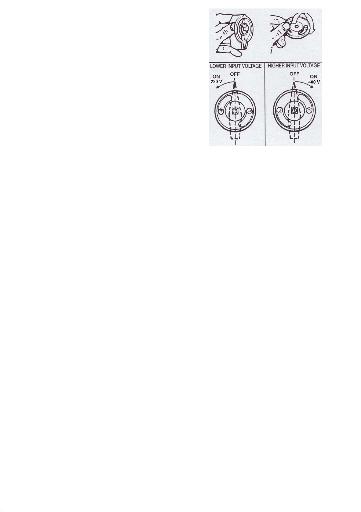
ВЫБОР НАПРЯЖЕНИЯ 230/400 В
(в случае если Ваш аппарат оснащен переключателем)
Чтобы изменить напряжение, открутите кнопку переключателя.
За ней находится пластиковый ку
установить кнопку в нужное положение (230 или 400 В).
сокую температуру продолжительное время.
этому для сохранения правильного
ом, поместите электрод на
лачок. Он позволяет
DANISH
BESKRIVELSE AF APPARATET
De bærbare lysbuesvejseapparater er enfasede svejseapparater
med vekselstrøm 220V/50 Hz eller 400V/60 Hz. På grund af deres
kompakte og stabile konstruktion er apparaterne velegnede under
næsten al le forhold. Materialerne som apparaterne er lavet af, er
af høj kvalitet og har derfor en meget lang levetid.
DE FORSKELLIGE PÅSKRIFTER OG MÆRKATERNES
BETYDNING
Enkelt-fase Transformator
Henhoerende karakteristiske
EN 60974-1
Normen reference
EN 60974-6
Enfaset vekselspænding
1 ~
Trefaset vekselspænding
3 ~
УСТАНОВКА КОЛЕСИКОВ И РУКОЯТКИ
(в случае если Ваш аппарат оснащен этими приспособлениями)
РУКОЯТКА
Винты уже привинчены на тело, поэтому:
1) Вывинтите винты parker и установьте ручку для того чтобы
сделать отверстия соответствовать.
2) Закрепите винты.
ВЫДВИНУТАЯ РУЧКА
1) Вставьте приспособление в отверстие пластиковой рукоятки.
2) Прикрепите его к рукоятке с помощью винта.
СУППОРТ
ты уже прикручены к нижней части корпуса, поэтому:
Вин
1) Открутите крепежные винты и поместите суппорт так, чтобы
отверстия совпали.
2) Закрепите винты.
КОЛЕСИКИ
1) Вставьте ось в отверстие.
2) Установите колесики на ось.
3) Установите на ось пробки чтобы закрепить колесики.
U 0 … (V)
U 1 … (V/Hz)
I 2 … (A)
Ø (mm)
t w
t
I
(A)
1 max
IP21
H
Nominel åbne kredsloeb spænding
Nominelle værdier i netspænding og
hyppighed
Elektrisk strøm til svejsning
Diameter på de elektroder
Er belastningen tid for hver cyklus.
Er de reset tid for hver cyklus.
Liniens maksimale strømforbrug.
Svejsningerne enhedens beskyttelse
klasse
Transformerens isoleringsklasse
Svejsemaskine beregnet til anvendelse
i omgivelser, hvor der er øget fare for
elektrisk stød
SVEJSEAPPARATETS TEKNISKE INFORMATION
Ved brug af spændingsanviseren på apparatet kan det kontrolleres
at reguleringen er korrekt.
- Ved en temperatur på 20 grader kan der svejses med apparatet
uden at termorelæet slår til. I varm tilstand med n0 antal af
overtrukkede elektroder, og for et nh antal af overtrukkede
elektroder, uden at termorelæet slår til.
- Svejseapparatet er udstyret med et termorelæ, som automatisk
afbryder strømtilførslen. Når temperaturen er faldet til et niveau
som igen tillader drift, genstarter apparatet automatisk.
Den Magneto-thermiske kontakt samt sikringernes
arbejdsnominalstrøm skal min være16A.
- Svejseapparatet er egnet til svejsning med følgende ledninger:
- Massetangen skal forbindes så godt med materialet der skal
svejses at der opstår en god kontakt. Berøringspunkterne skal
være helt rengjorte for f.eks. smørefedt, rust eller andre urenheder,
for at opnå en optimal svejsning.
- Svejseapparatet er udstyret med en hovedkontakt, en gul
signallampe, et termorelæ, og med et håndhjul hvormed
svejsestrømmen kan reguleres. Reguleringen skal stå i forhold til
svejsestrømsværdierne og I forhold til elektrodediameteren.
- GIV AGT: Lampen lyser kun ved overbelastning
NYTTIGE SVEJSEINFORMATIONER
Stedet der skal svejses skal være rengjort for rust og maling.
Elektroden vælges du fra det materiale der skal svejses.
Vi anbefaler at de afprøver elektroden og strømstyrken på et stykke
affaldsmetal, fo r at se om resultatet bliver som ønsket. Først skal
De tage svejsehjælmen på, og derefter placere elektroden ca. 2
cm. over materialet der skal svejses. Strejf emnet der skal svejses
let med elektroden.
Svejseslagger må ikke fjernes før at svejsesømmen er afkølet. Der
kan svejses vider e på en søm efter at slaggerne er fjernet.
Svejseren skal forsøge at holde lysbuelængden k onstant. Da
elektroden langsomt bliver kortere skal svejseren langsomt føre
elektrodestangen tættere på materialet der svejses. Ved
svejsesømmens afslutning anbefales det at fjerne elektroden i
sømmens retning, for at undgå at der danner sig en porøs afslu
tning.
UDSKIFTNING AF LEDNINGEN
En ny ledning skal have en min. diameter på 3 x 1,5 mm 2 og
længden skal mindst svare til den originale lednings længde. Følg
monteringsvejledningen til modellerne 220 V/400 V.
- This is an A class welding machines, designed for industrial applications: the use in different environments could generate disturbs able
to influence the electromagnetic compatibility. It is an end user obligation the correct use of the welding machine.
- La saldatrice è di classe A ed è principalmente destinata ad uso industriale. L’uso in ambienti diversi può causare disturbi che
influenzano la compatibilità elettromagnetica. E’ cura dell’utilizzatore l’uso corretto della saldatrice.
- Das Schweißgerät ist von A Klasse und ist hauptsächlich für den industriellen Gebrauch vorgesehen. Der Gebrauch in anderen
Umgebungen kann Störungen verursachen, welche die elektromagnetische Kompatibilität beeinflussen. Der korrekte Gebrauch des
Schweißgerätes ist Sache des Benutzers.
- Esto equipo de soldar es de clase A , eso significa que su uso es de tipo industrial. El uso in ambientes diferentes puede causar
molestias al sistema de compatibilidad electromagnetica EMC. Es preocupacion del usuario el correcto utilizo del equipo!
- Сварочный аппарат класса А, предназначен для промышленного использования. Эксплуатация в иных внешних
условиях может привести к проблемам электромагнитной совместимости. Перед эксплуатацией аппарата
обязательно ознакомтесь с интрукцией
MONTERINGSANVISNING TIL GREB OG HJUL
(HVIS DET HØRER MED TIL MODELLEN)
GREB
De skruer er allerede skruet fast på kroppen, derfor
1) Unscrew skruer og sted for handling for at gøre de huller svarer.
2) Skruer Tommeskruerne igen stramning stærkt.
UDVIDET HÅNDTERE
1) Stik transportbø jlen i den dertil indrettede åbning på
plastichåndtaget.
2) Monter transportbøjlen på håndtaget med en egnet skrue.
STØTTEBEN:
1) Monter støttebenet med monteringsskruerne.
2) Skruer Tommeskruerne igen stramning stærkt.
HJUL:
1) Stil hjulakslen i de borede huller i bunden af kabinettet.
2) Sæt hjulene på ak slen.
3) Monter hjulene på akslen ved hjælp at plasticpropperne
.
 Loading...