


ITALIANO
DESCRIZIONE GENERALE
Saldatrici a filo continuo con possibilità di saldare filo animato senza gas
o con g as per la saldat ura di acciaio, i nox e alluminio.
1. INFORMAZIONI TECNICHE SULLA SALDATRICE
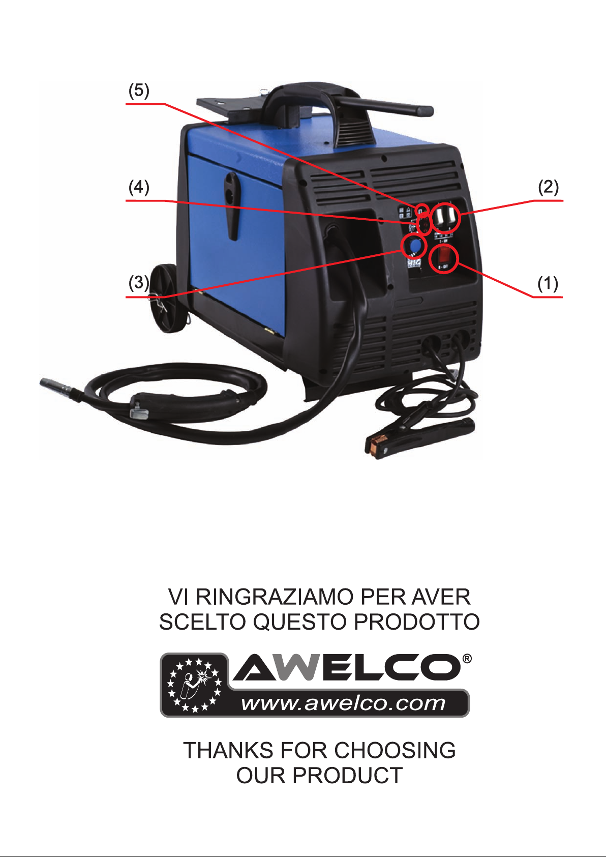
Per mettere in funzione la saldatrice agire sull’interruttore generale
ON/OFF (1).
L’int ensità della c orrente di sal datura erog ata è regolabi le per mezzo di
due dev iat or i (2).
La velocità del filo si regola mediante la manopola di variazione della
velocità (3). Tre leds rossi visualizzano il livello della velocità (4).
La saldatrice è dotata di un dispositivo di protezione termica che
interrompe automaticamente l’erogazione della corrente di saldatura
quand o si ragg iungono t emper ature el evate; i n tal cas o si acce nde una
spia luminosa gialla (5). Quando la temperatura si è sufficientemente
abbassata e ha raggiunto il livello che permette un corretto
funzionamento della saldatrice, la spia luminosa gialla si spegne. La
macchina è alimentata automaticamente e si possono riprendere le
oper azi on i di s ald at ur a.
2. INSTALLAZIONE
2.1. CONNESSIONE ELETTRICA
La macchina è fornita di uno specifico cavo di alimentazione che non
dovrebbe essere prolungato; nel caso ciò fosse necessario occorrerebbe
usarne uno di sezione uguale a quello della macchina.
Prima di collegare la saldatrice alla presa di corrente, accertarsi che il
voltag g io si a u guale a quell o del l a m acc hi na e ch e l a pot en z a erog at a sia
suffic iente ad alim entare l a macc hina a pieno c aric o; accert arsi, inoltr e,
che l’impianto di alimentazione sia provvist o di un adegu ato sistema di
mess a a t err a.
Tensio ne d i alim ent az io ne
La tensione di alimentazione è di 23 0 V.
2.2. COLLEGAMENTO DEL GAS (PER I MODELLI PREDISPOSTI)
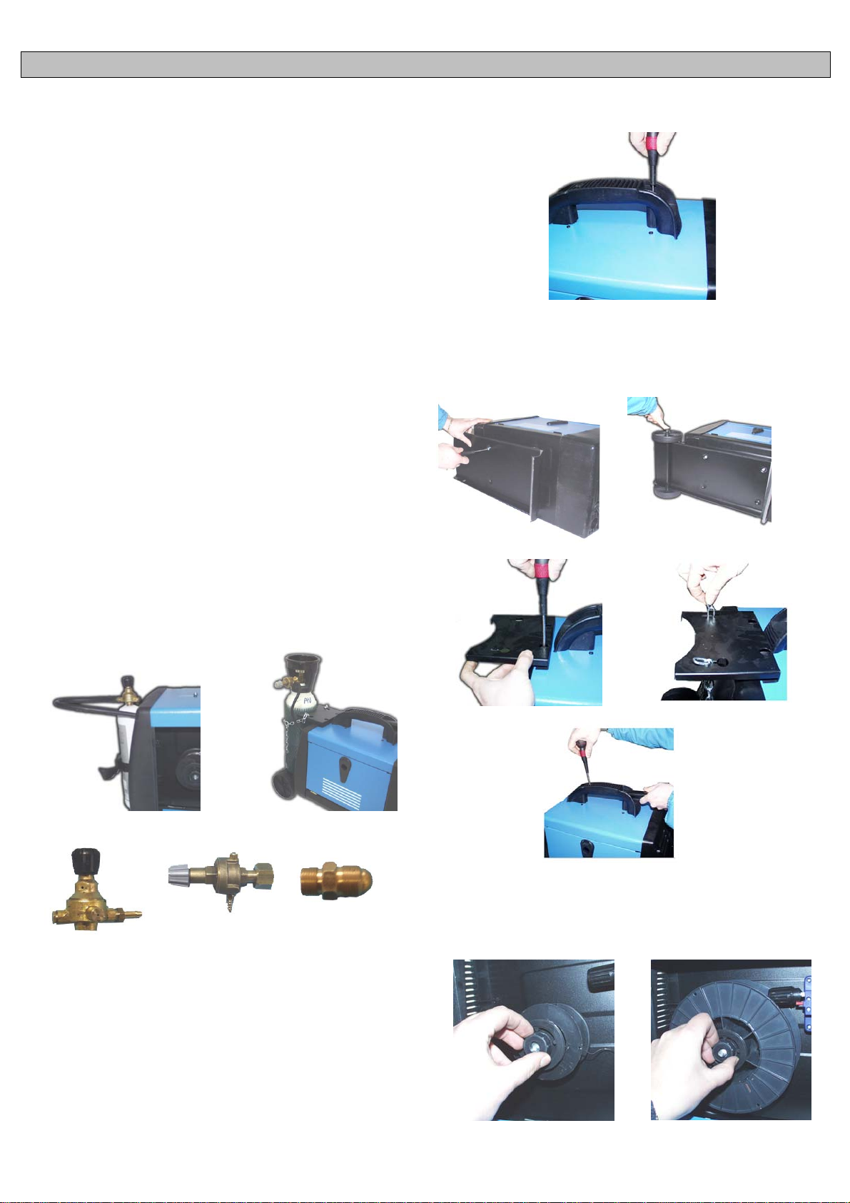
La bombola del gas deve essere posta nell’apposito vano porta-bombola
nella parte posteriore della macchina sull’apposita piattaforma. Nel
collegamento alla bombola verificare che tutti gli attacchi siano ben
serrati.
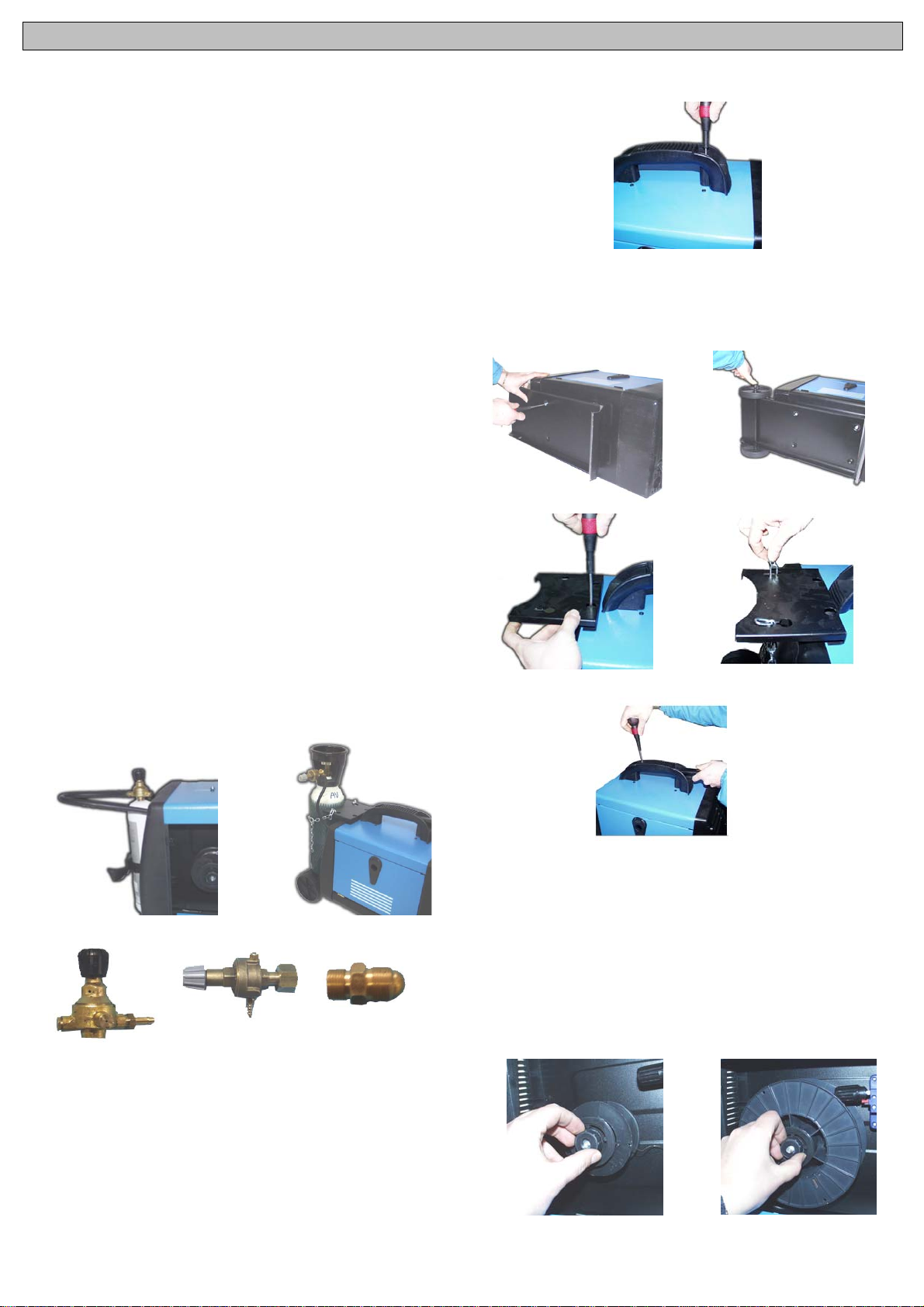
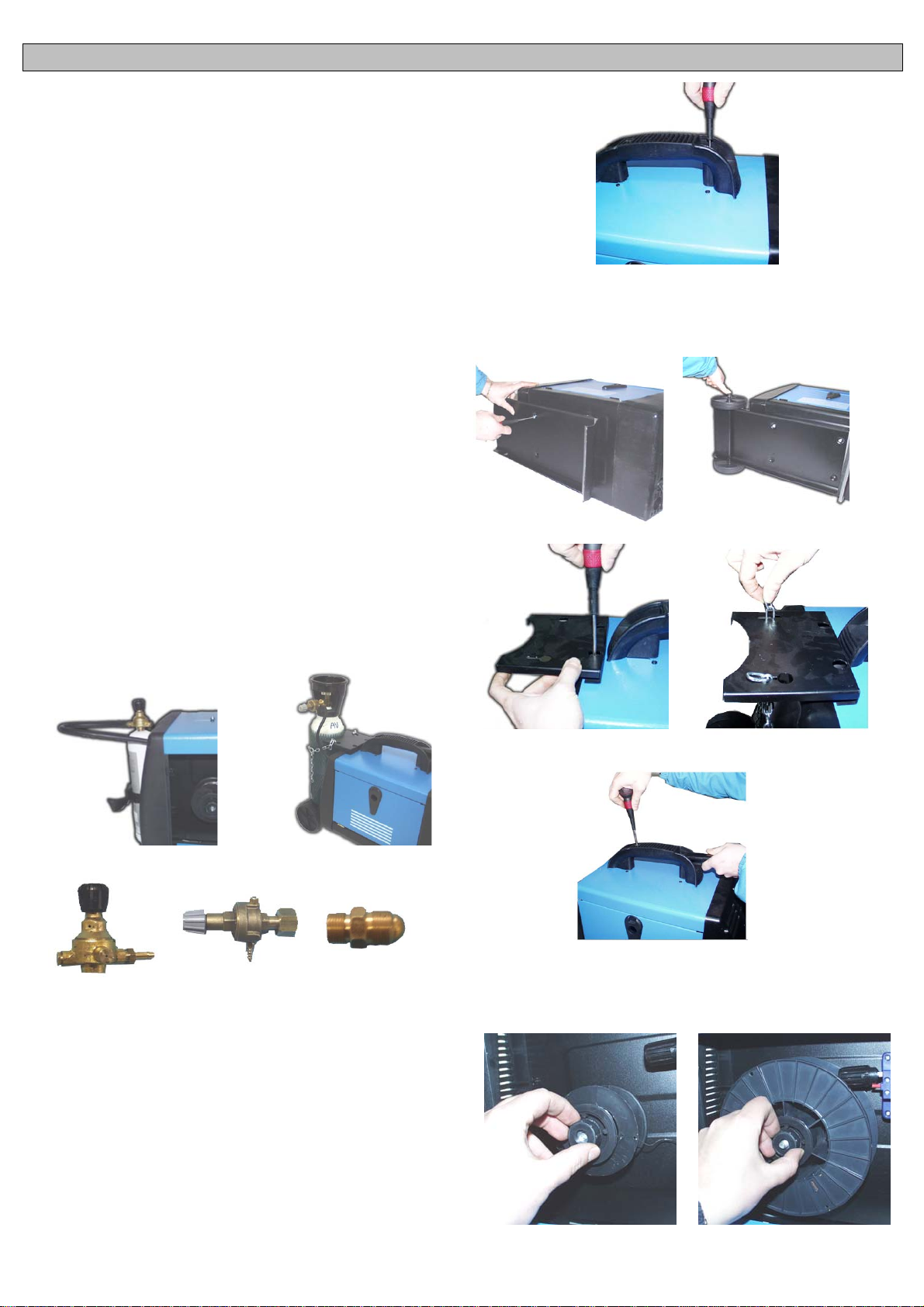
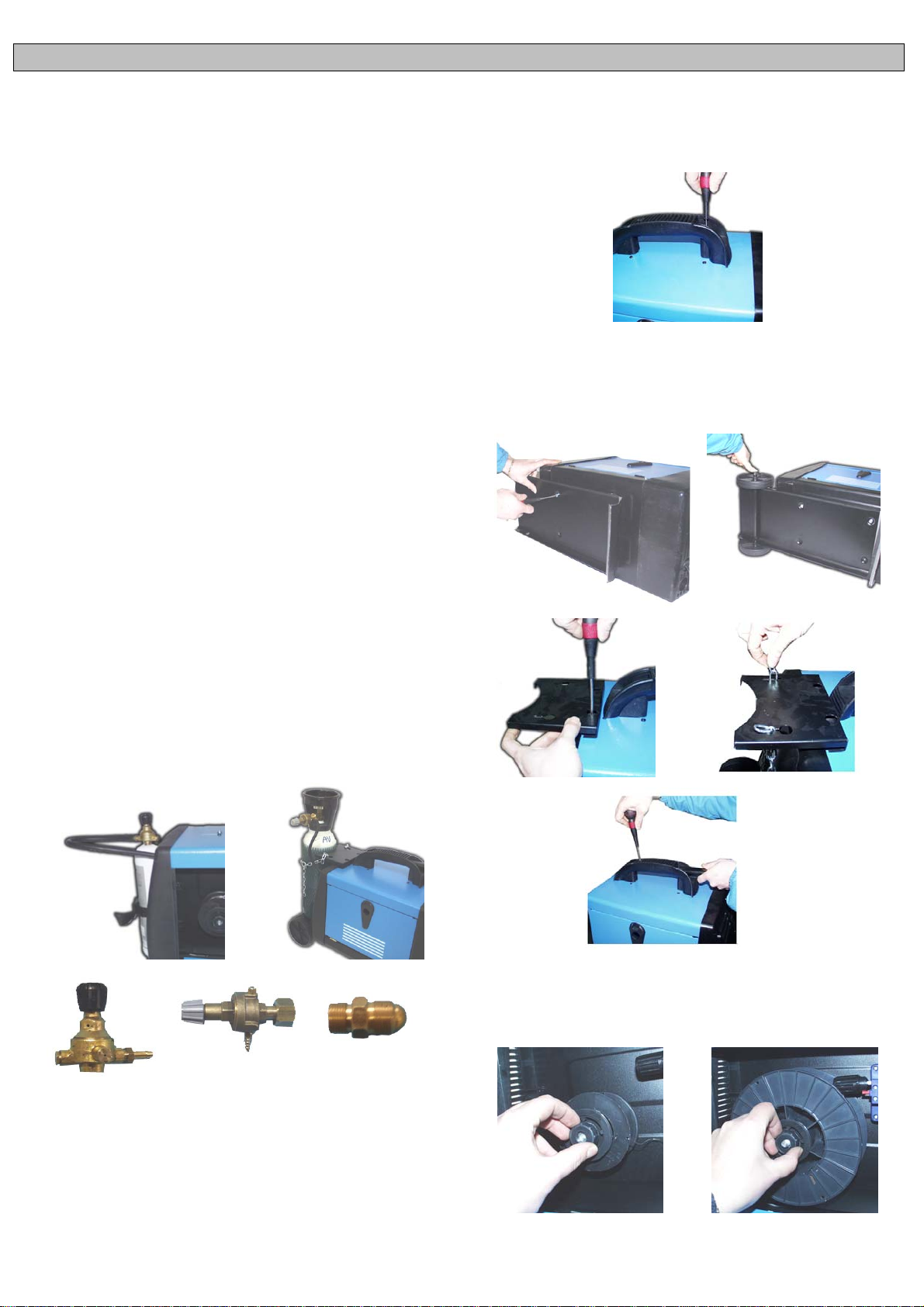
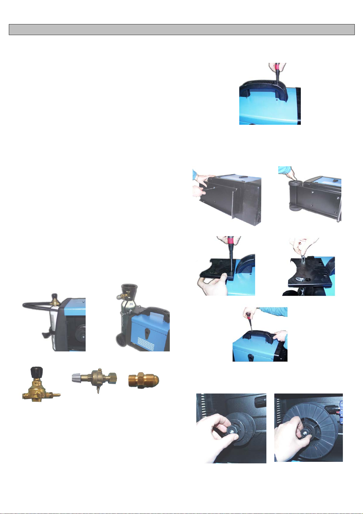
Posizionare la bomboletta da 1Kg. di gas (Opzionale) sul retro della
macchina nell’apposita sede e serrate con le cinghie in dotazione (Fig.1).
Se la macchina è equipaggiata con una bombola di gas da 5Kg.
(Opzionale), dopo aver montato il kit ruote posizionare la bombola sul
supp orto e serrare c on la cat ena (Fig.2).
Se usate il CO
Chiedetelo al vostro rivenditore.
, è possibile che abbiate bisogno di un adattatore.
2
2.4. MONTAGGIO MANIGLIA
Mont are l a man igl i a sec on d o la fig ur a us and o le vit i in dotazion e.
2.5. MONTAGGIO KIT RUOTE (OPTIONAL)
Alcuni modelli sono dotati di un kit ruote comprendente: Piedino
d’appoggio, pianale, assale, portabombola, catena di fissaggio, maniglia
di trascinamento, 2 ruote in plas tica e d ue tappi o coppiglie di bloccaggi o.
Segu ir e lo schem a s eg u ent e per il montaggi o del kit .
Fig. 2
Regulatore 1 Kg Regulatore 5 Kg Adattatore CO
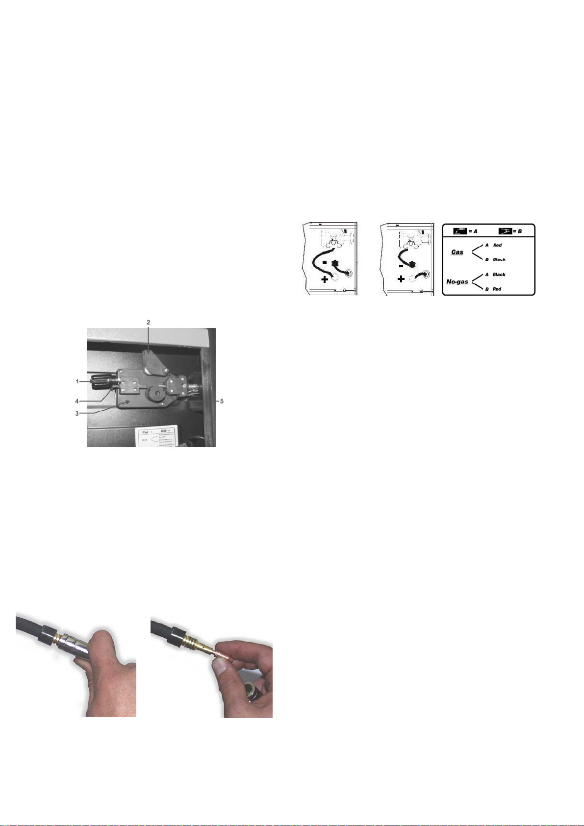
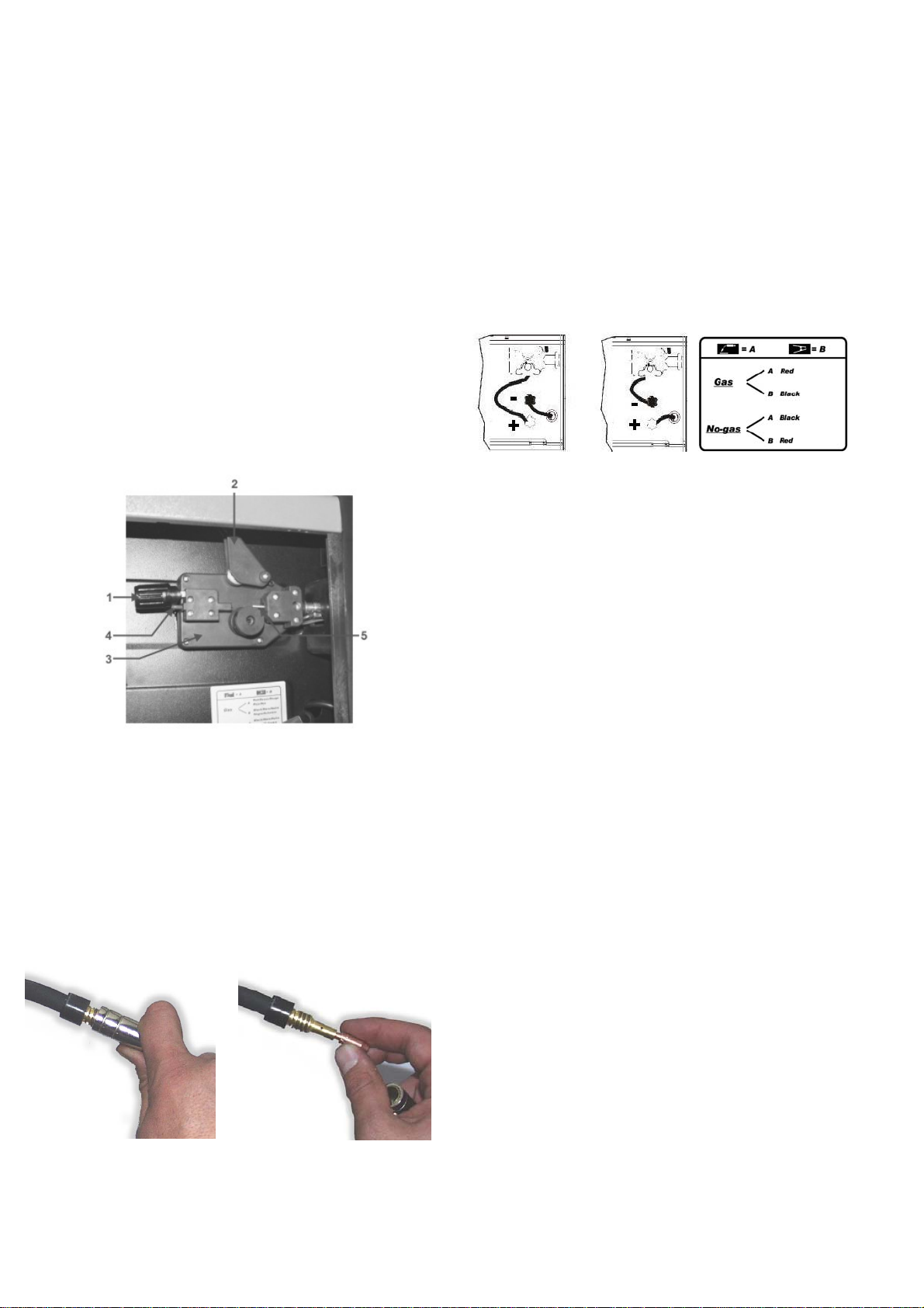
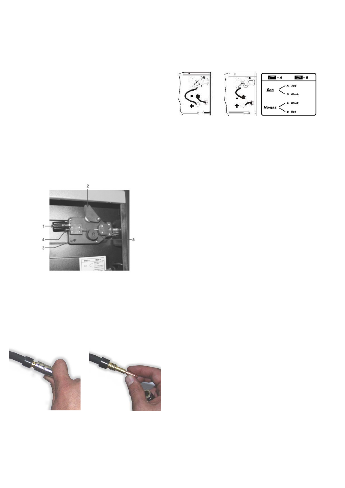
2.3. COLLEGAMENTO DELLA MASSA
La macchina è fornita di un cavo di massa collegato ad una pinza.
Verificare che ci sia un perfetto contatto tra la pinza e il pezzo da saldare.
Pulir e b ene i c ontatti in m od o ch e n on ci siano gr assi, rugg i n e o im p urit à.
Un cont at t o n on p er f ett o r id uce la cap ac ità d i s ald at ura e può c a us ar e, d i
cons eguenza, una s aldatur a non s oddisf acente. Il ter minale della pinza
di massa va inserito nell’uscita polo positivo (+) per il procedimento di
saldatura senza gas; va inserito, invece, nell’uscita polo negativo (-) per il
proced i m ent o di s ald at ur a con g as.
Fig. 1
2
Per il montaggio ruote segu ire le s eguenti is truzi oni:
1. Introdurre l’assale negli appositi fori sul fondo posteriore della
carrozzeria.
2. Collegare le ruote all’assale.
3. Bloccare le ruote con le coppiglie o con i tappi di bloccaggio.
4. Fissare il supporto anteriore con le viti parker date in dotazione
5. Fissare il prolungamento maniglia avvitandolo sulla maniglia fissa in
corrispondenza del foro.
3. MONTAGGIO BOBINA, FILO E TORCIA
3.1. MON T AG G IO BO BI N A
Le macc hin e pos s on o ut iliz z ar e ind ifferentem en te bobine da ø100 e
ø200. L’aspo possied e una frizione, al fine di mantenere sempre il filo
rigido.
ø100
ø200
3.2. MOTORE TRAINAFILO
Assicurarsi che il rullino d’avanzamento filo abbia la cava di diametro
uguale a quella del filo. Il rullino porta stampigliato sul fianco il diametro
del filo che s i può adoperare. Per s aldare con filo pien o con GAS di
protezione sostituire il rullino del gruppo trainafilo con rullino con
scanalatura avente forma V per il f il o in acciaio e a for m a d i U per il filo di
alluminio. Richiedere tali rullini e il riduttore di pressione al vostro
rivenditore di fiducia o alla società costruttitrice se si intende usare la
saldatrice con g as di pr ot ez ion e.
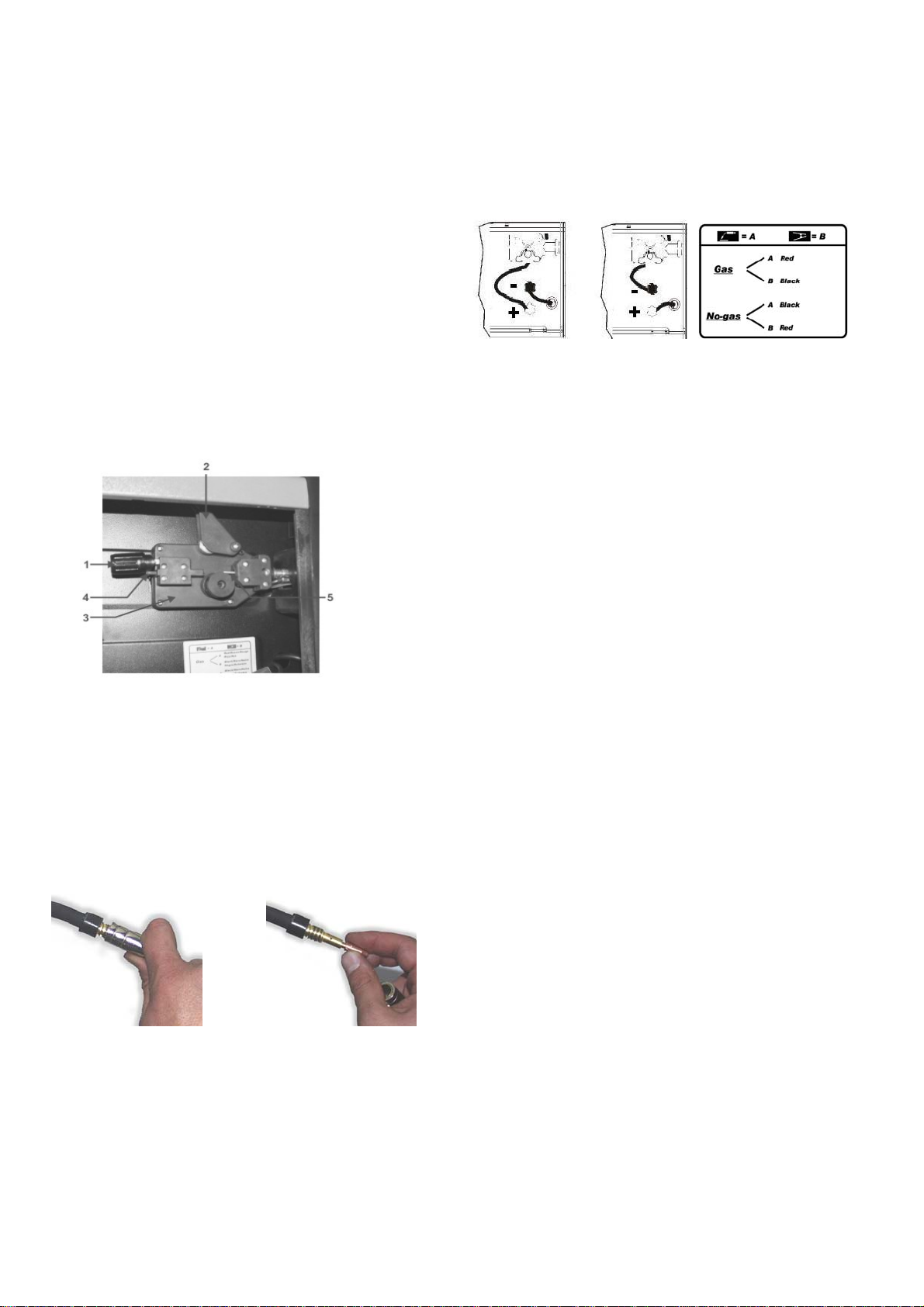
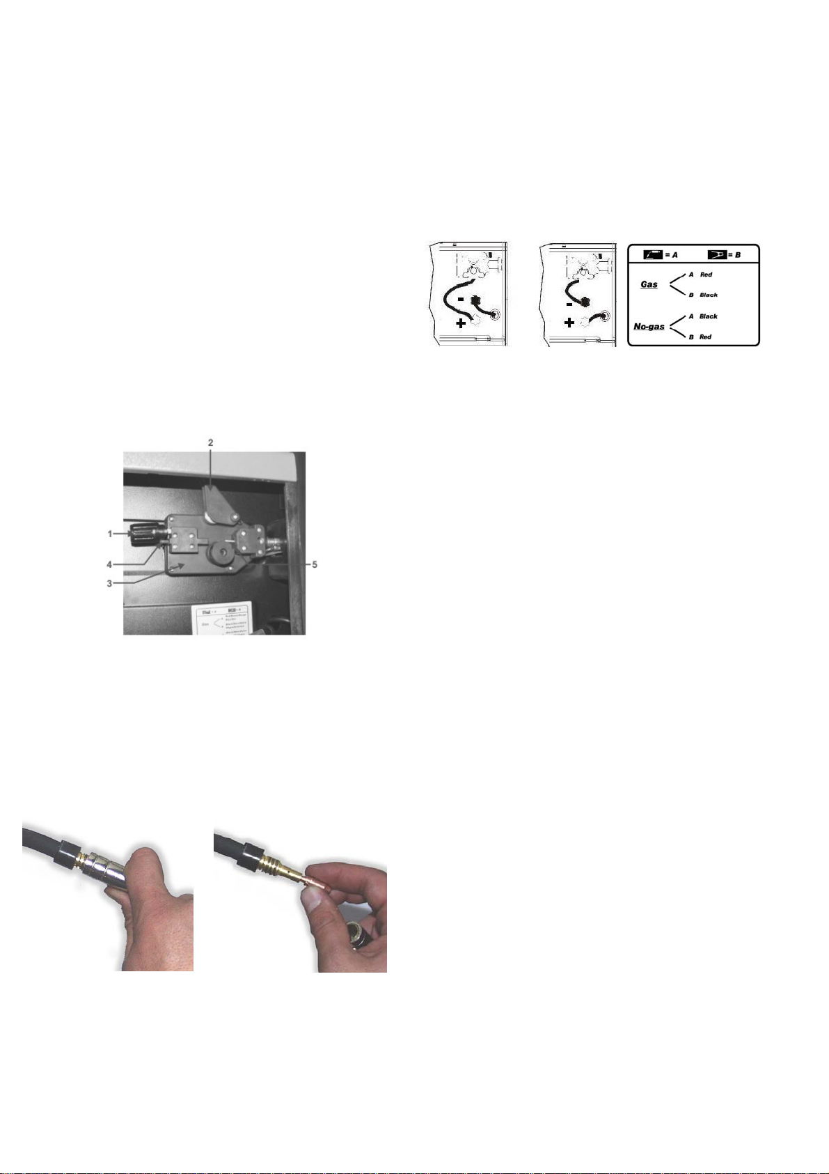
3.3. INS ER IM E NT O DEL F ILO
1. Disinnestare il braccetto con molla (1) e ruotarlo verso l’alto (2) in
modo da allontanarlo dal rullino (3). Assicuratevi che il rullino porti
stampigliato nel lato a vista il diametro del filo che si sta usando.
2. Con attenzione staccare il filo dalla bobina portafilo. Per evitare noiosi
sbob inamenti tener lo in tensione fino al pu nto (5).
3. Tagliare i primi 100 mm di filo o comunque tutta la parte non
perfet t am ente diritt a.
4. Inserire il filo nella guida (4), sopra il rullino (3) e quindi inserirlo nel
tubo capillare (5).
5. Chiud ere il br accetto pr emifil o lascian do la moll a caricat a. Ruotar e la
bobina in modo da allentare ulteriormente il filo.
6. La man opola d i regol azi one dell a press ione d el filo è r egolat a a met à
pressi one. Nel caso l a pr ess i on e sia eccessi va (r isc h io di ap pi att i r e il filo) ,
svitare la manopola in modo da ridurre la pressione. Una pressione
maggore è richiesta nel caso si usi filo da 0,6 mm. Se il rullino guida
slitta, bisogna aumentare la pressione fino a che il filo avanzi
regolarmente.
7. Togliere l’ugello guida gas e la punta di contatto.dalla pistola della
torcia.
8. Metter l’interruttore in p osizione “ON” (“ I “).
9. Tirare il cavo della torcia in modo che sia ben dir itto.
10.Pr emere il pulsant e della torcia ed aliment are il filo fino a che esso
appaia al l’est rem ità del la torc ia (att enzi one non puntar e la pist ola cont ro
voi o altr e persone), qu ind i ri l asc i are il p uls ant e.
11.Spegnere la macchina mettendoin posizione “OFF” ( “O”).
12.R iposizion ar e la punta di cont att o e l’ug ell o g as.
13.T agli are il fil o di 6-10 mm oltr e la punt a. Ora la macc hi na è pront a per
saldare.
3.4. COLLEGAMENTO DELLA TORCIA
La torcia è collegata direttam ente e, quindi è già pr onta per l’uso. Un a
eventuale sostituzione va fatta con molta cura. E’pref eribile farla eseguire
da un tecnico esperto. Per sostituire la punta guida gas è sufficiente
svitare oppure tirare verso l’esterno. La punta guida gas va tolta ogni
qual volta bisogna sostituire l’ugello guidafilo. Tale ugello deve ess ere
sempre del diametro appropriato a quello del filo. Tenere sempre
perfet t am ente pulita l a punt a gu i da gas.
4. MODI DI SALDATURA
4.1. SALDATURA IN CONTINUO
E’ il sist ema maggior mente adop erat o. Una volta pr eparat a la macchin a
è suffic iente pr emere il puls ante dell a torc ia ed inizi are le oper azioni di
saldat ur a. P er s m ett ere di s al d are è suffic i ent e rilasc i are i l p u ls ant e d el l a
torcia.
4.2. PRES S ION E DEL G AS
La pressione del gas va regolata in modo che l’erogazione corrisponda
ad un valore compreso tra i 6 e i 12 litri.
4.3. SAL D AT UR A G AS – NO GAS
4.3.1. Gas – Collegare il morsetto della torcia nell’uscita positiva “+” e la
pinza della massa nell’uscita negativa “-”.
4.3.2. No-Gas – (Solo per i modelli che hanno questa predisposizione)
Effettuare il cambio di polarità, collegare, quindi, la pinza della massa
nella connessione positiva “+” e il morsetto della torcia nella connessione
negativa “-”.
4.4. SAL D AT UR A MI G - MAG
A) M I G = M etal Inert Gas
B) M AG = Metal Active Gas
I du e procedim enti son o perfett amente equivalent i, ciò ch e cambi a è il
tipo di gas adoperato. Nel caso A il gas adoperato è l’ARGON (gas
inert e). Nel caso B il gas adoperat o e il CO
(gas attivo). Per saldare le
2
leghe d’alluminio o d’inox è necessario adoperare ARGON puro o al
massi mo una misc ela comp osta dall’ 80% di ARG ON e dal 20% di CO
Si può adop er are la CO
da sola soltanto nel caso di saldatura di acciaio
2
.
2
al carbonio (ferro).
5. GUI DA ALLA SALDATURA
5.1. REGOLA G ENERALE
Quando la saldatura è regolata al minimo è necessario che la lunghezza
dell’arco sia piccola. Questo si ottiene tenendo la torcia il più vicino
poss ibi le al p ezz o da l avorare e c on un a inc l in az ion e d i cir c a 60 gradi. L a
lunghezza dell’arco può essere aumentata man mano che si aumenta
l’int ens it à d i c orrente, al m as s im o s i pu ò arr iv ar e ad u n a dis t an z a d i cir c a
20mm.
5.2. CONSIGLI DI CARATTERE GENERALE
Di tant o in tanto alc u n i difetti s i pos sono ver if ic ar e n ell a s al d atura. Qu est i
difetti si possono eliminare prestando attenzione ad alcuni suggerimenti
che qui di s egu it o Vi prop on i am o:
- Porosità
Piccoli fori nella saldatura, non dissimili da quelli della superficie della
cioccolata, possono essere caus ati da interruzione del flusso di gas o
talvolta dall’in-clusione di piccoli c orpi est ranei. Il rimedio usuale è molar e
la saldatur a e rif are la saldatura. Prima, però, bis ogna controllare il flusso
di gas (circa 8 litri/minuto), pulire benissimo la zona di lavoro e poi
inclinare correttamente la torcia mentre si salda.
- Spruzzatura
Piccole gocce di metallo fuso che provengono dall’arco di saldatura.
In piccole quantità è inevitabile, ma si può ridurre al minimo regolando
bene la corrente ed i l fluss o di gas e tenendo pulita la torcia.
- Saldat ur a str ett a e arrotondat a
È causata dall’avanzamento veloce della torcia oppure dal gas non
regolato bene.
- Saldatura spessa e larga
Può essere causata da un avanzamento troppo lento della t orcia.
- Filo bruciato dietro
Può essere causato da un avanzamento del filo lento, dalla punta
guidaf ilo al lent at a o consu mat a, fi lo di bass a qu alit à, becc uc cio gu id agas
troppo chiuso o corr ente troppo elevata.
- Scarsa penetrazione
Può ess ere caus ata da un avanzament o tropp o veloce della torcia, da
corrente troppo bassa, da alimentazione del filo non corretta, da polarità
invert it a, sm ussi e dist an z a tr a i lem b i ins uff ic i ent e. C ur ar e la r eg ol az i on e
dei param et r i op er at ivi e mi g li orar e l a prep ar az i on e dei p ez zi da s al dar e.
- Foratura del pezzo
Può essere causata dal movimento troppo lento della torcia, corrente
tropp o el evata o non corr ett a ali m ent az i one d el f il o.
- Forte spruzzatura e porosit à.
Può ess ere caus ato da un a distan za ecc essiva del beccucc io guid agas
dal pezzo, da sporco sui pezzi, da scarso flusso di gas o da corrente
bassa. Bisogna verificare i due parametri, ricordando che il gas non deve
esser e inferi ore a 78 lit ri/mi n. e che la c orrent e di saldat ura dev e esser e
appropriata al diametro del filo che si sta utilizzando. E’ preferibile avere
un ridutt or e di press ion e di entr at a e di usc ita. S ul manom etr o di usc ita è
poss ibi le leg g er e anc h e la port ata espres s a in litri.
- Instabilità d’arco
Può essere causata da tensione insufficiente, avanzamento filo
f
irreg olare, gas di pr ot ez ion e ins uf ficient e.
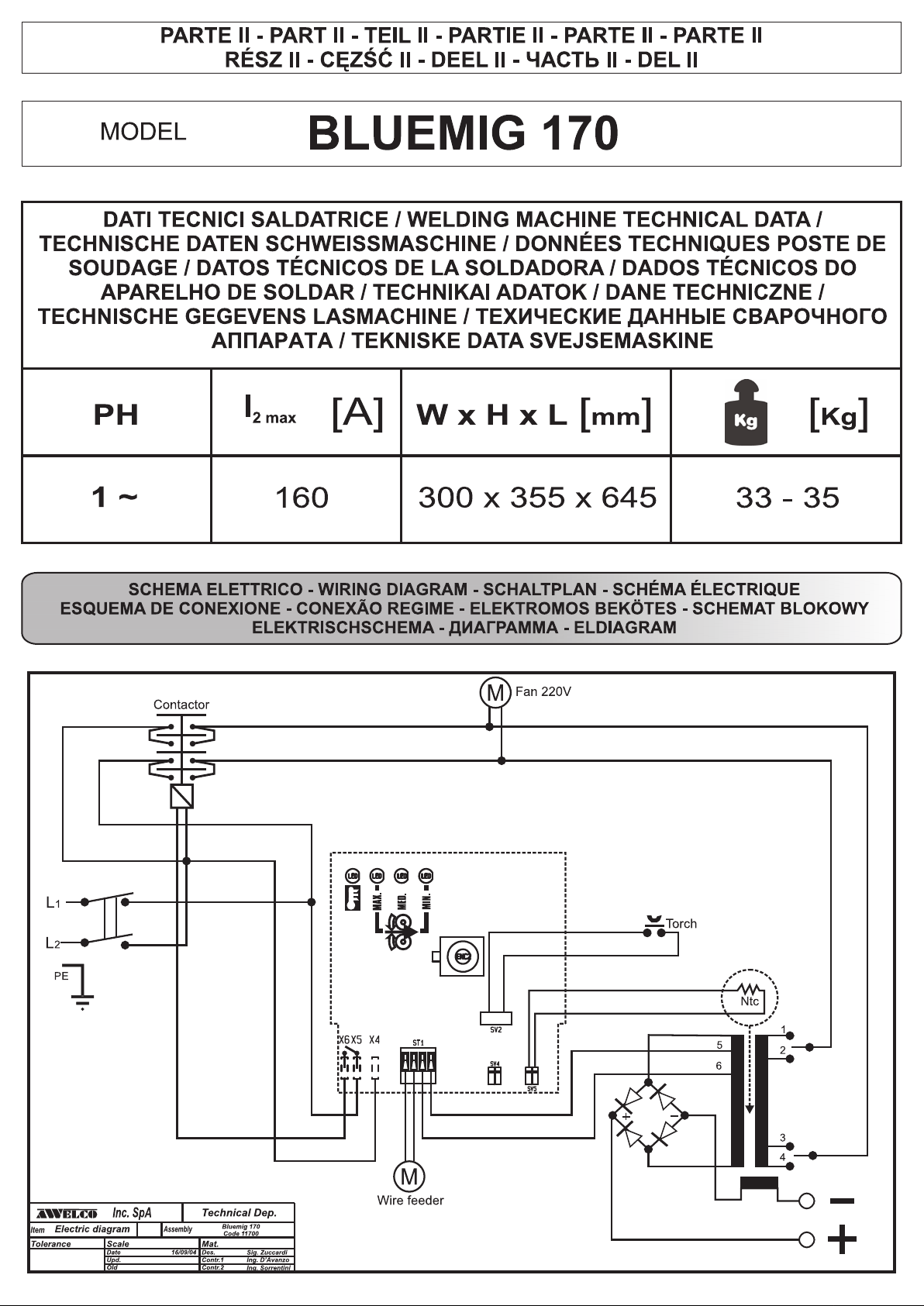
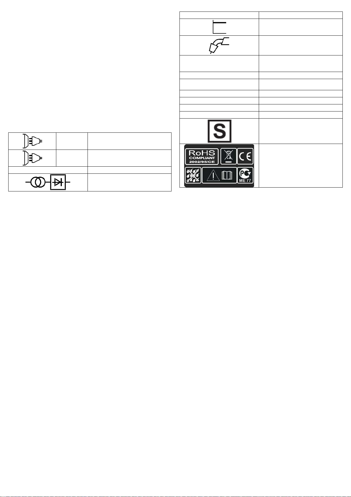
SIGNIFICATO DELLE SCRITTE E DEI SIMBOLI
1 ~
Alimentazione monofase
3 ~
U 0 … (V)
GUSTO
EN 60974 - 1
Il filo non avanza quando
la ruota motrice gira
Alimentazione del filo a scatti o
intermittente
Arco spent o
Cordatura di saldatura poroso
La macchina cessa improvvisa me nt e
di funzionare dopo un uso prolungato
Alimentazione trifase
Valore nominale della tensione di
uscit a a vuot o
Trasformatore raddrizzatore
Norma di riferiment o
Caratteristica piatta
Saldatura a filo MIG-MAG
RICERCA DEL GUASTO
RAGIONI
1) Sporco sulla punt a
dell’uggello gui da fil o
2) La frizione dell’aspo
svolgitore è eccessiva
3) Torcia difettosa
1) Ugello di contatto difettoso
2) Bruciature nell’ugello
di contatto
3) Sporco sul so l c o del l a ru ot a
motrice
4) Solco sulla ruota motrice
consumato
1) Cattivo contatto tra pinza di
massa e pez z o
2) Corto circuito tra ugello di
contatto e tubo guidagas
1) Mancanza dello scudo di gas
causato d a in cr ostazioni
nell’ugello guidagas
2) Distanz a o inclinazion e
sbagliata della torcia
3) Troppo poco gas
4) Pezzi umidi
5) Pezzi con molta ruggine
1) La macchina si è surrisc al d ata
per un uso ec c essi v o e la
protezione termica è intervenuta
U 1 … (V/Hz)
I 2 … (A)
I
… (A)
1 max
I
… (A)
1 ef
X
IP21
H
Valore nominale della tensione di
alimentazione e della frequenza
Corrente di saldatura
Corrent e m ass i m a assorbita
Corrent e ef fettiva di alimentazi on e
Duty cycle
Grado di pr otezione d ell a s ald at rice
Classe di isolamento del
trasformatore
Saldatrice adatta all’uso in un
ambien te con ris chio acc resciut o di
scoss e elett riche
Simboli riferiti a norme di sicurezza
RIMEDI
Soffiar e co n ar ia
Allentare
Controllare guaina guidafilo
Sostituire
Sostituire
Pulire
Sostituire
Stringere la pinza e controllare
Pulire oppure sostituire ugello di contatto
e
ugello guidaga s
Pulire dalle incrostazioni o sostituire
La distanza tra la torcia e il pezzo deve
essere di 5 - 10 mm; l’inclinazione non
meno di 60° risp et t o al pez z o
Aument ar e la quantità
Asciug are con una pistola ad aria cal da o
altro mezzo
Pulire i pezzi dalla ruggine
Lasciare raffreddare la macchina per
almeno 20 – 30 minuti
ENGLISH
GENERAL DESCRIPTION
MIG wel ders whic h can weld f lux cored g asless wir e or with ga s for the
weld ing ofmild steel, stainless steel and aluminium.
1. TECHNICAL INFORMATION
To switch on the welding machine operate t he main switch (1).
The int ens ity of t he su pplied weld ing cur rent can be adjus ted by me ans
of two switches (2).
The wire speed regulation occurs through the knob of the encoder
(3).Three red leds show the actual speed (4) .
The machine is fitted with a thermal overload protection which will
automatically interrupt the welding current on reaching excessive
temperatures; in which instance a yellow pilot light will switch on (5).
Once the temperature has decreased to a level low enough to allow
welding, the yellow light will sw itch itself off and t he machine is again
ready for use.
2. INSTALLATION
2.1. ELEC T RICAL CONNEC T I ON
The welding machine is fitted with a suitable primary cable which we
strong ly rec ommen d you t o do not extend: if it is n ecess ary to ext end it,
use a cable having the sam e section of th e prim ary cable.
Before connecting the machine to the outlet, check that your supply
voltage is like the machine’s voltage and that the furneshed power is
sufficient to feed t he full load machine. Make sure that the electric plant is
prov ided wit h a sufficient earth connection.
Supply vo lt ag e
The supply voltage is of 230V.
2.2. GAS CONNECTION (FOR MODELS WHERE PROVIDED)
The g as bot tle s h ould b e p laced on t he s uit abl e plat for m pr ovid ed at th e
rear of the welding machine and secured with the retaining chain
provided, or in case of the remaining models, it should be placed on the
platform. Verify that all connecti ons are well closed.
Place t he 1 K g. gas b ottle ( OPTION AL) in t he rear side an d clam p the
belt (Pic .1). If th e machi ne is equip ped by a 5 kg gas (OP TION AL), after
the wh eel k it proced ur e has b e en d on e (see wheel kit ass em bl ag e) p lace
the gas bottle on the support and lock with the chain (Pic.2).
If CO
gas is used, it is possible that a CO2 gas heater will be required.
2
This should be requested to your gas supplier. Check that all connections
are tight and with no leaks.
2.5. WHEEL KIT ASSEMBLAGE (OPTIONAL)
Some models are equipped with a wheel kit containing:leg, gas bottle
support, axle, gas bottle holder, chain, handle extension, wheels, axle
caps. See the pictur e to mount the kit .
Pic. 1
1 kg regulator 5 kg. regulator CO
2.3. EARTH CONNECTION
A suit able eart h cab le c onn ect ed to a cl amp is sup pli ed w ith t he w eldin g
machi ne. Th e eart h c lam p sh ou ld b e att ac h ed to th e work p iec e it s elf. Th e
must be very good connection wherever made, as a poor or dirty
conn ection wi ll produc e diffic ult weld ing cond itions an d could r esult in a
bad weld. For No-Gas welding, the cable’s terminal must be plugged into
posit ive (+) out lets ; on the cont rary, it must b e plug ged int o negati ve (-)
for gas welding.
2.4. HANDLE ASSEMBLAGE.
Ass emb le th e hand l e as in th e pict ur e 5 usi ng th e equ ip p ed screws.
Pic. 2
Adapter
2
3. SPOOL WIR E AND TORC H IN ST ALLATION
3.1. SPOOLS INSTALLATION
The models can indifferently mounth the ø100 and ø200 spools. The hub
is predisposed with a clutch in order to always maintain the wire stiff.
ø100
ø200
3.2. WIRE-FEEDER MOTOR
Make s ure t hat th e si ze of th e gr oove in t he f eed r oll c or resp on ds t o th e
welding wire size being used. The feed roll has the wire diameter
stamp ed on it s si de. Th e m ac hi n es ar e eq u ipp ed w ith prop er sh a gr en eed
rolls s uitabl e for wel ding w ith flux c ored wire wit hout gas protec tion. T o
weld w ith fu ll wire wit h GA S prot ect ion y ou hav e to rep lac e the rol l of th e
wire f eeder gr oup w hic h has V f orm for t he st eel w ir e and U form for the
alum inium wir e. If y ou inten d to use t he wel der with gas prot ection you
have to r equ ire s uch r olls and th e pr essur e r educ er t o your r etai ler or t o
th e b uil der soc i e t y .
3.3. FEEDING WIRE INTO THE WELDING TORCH
1. Rele ase the Spr ing Loaded Pr essur e Arm ( 1) rotat e the Idl e Roll Ar m
(2) aw ay from t he W ire Feed Dr ive R oll (3). E nsur e that th e groov e siz e
in the feedin g positi on on the drive r oll matches th e w ire siz e being used.
2. C arefu lly detac h the en d of th e wire fr om the sp ool. To pr event t he
spool from unwinding, maintain tension on the wire until after step 5.
3. Cut the bent portion of wire off and straighten the first 10 cm.
4. Thr ead t he wir e thr ou gh t he ingoi ng gu ide t ube ( 4), over th e dr ive r ol l
(3), and into the outgoing guide tub e (5).
5. Clos e th e idl e roll arm and lat ch th e spr ing load ed pr ess ure a rm ( 2) in
place. Rotate the spool counterclockwise if required to take up extra
slack in the wire.
6. The idle roll pressure adjustment wing nut is normally set for midposit ion on the pr essur e arm thread s. If feed ing pr ob lems occur bec ause
the wire is flattened excessively, tur n the pr essure adjustment counterclockw ise t o reduc e dis tort ion of th e wir e. Sli ghtly less pr ess ure m ay be
requ ired when using 0,6 mm wire. If the drive roll slips while feeding wire,
the press ur e sh ou l d be inc r eas ed u nt il th e wir e feed s prop erly.
7. Remov e g as noz z le and c ontact tip fr om en d of gun.
8. Turn the m achine ON (“I”).
9. Straighten the gun cable as sembly.
10. Depress the gun trigger switch and feed welding wire through the gun
and c able. ( Point gu n aw ay fr om your self an d oth ers w hil e feedi ng wire. )
Release gun trigger after wire appears at end of gun.
11. Turn the machine OFF (“O”).
12. Rep lac e c ont act tip an d gas n oz z le.
13. Cut t he wire off 6 – 10 mm fr om the end of the tip. The mach ine is
now ready to weld.
3.4. TORCH CONNECTION
The torc h is c onnect ed d irectly t o the w eldin g mach ine s o it is r eady f or
use. A pr obab le rep lacem ent of t he tor ch mus t be don e with c are an d if
possible by a technician. To replace contact tips, it is necessary to
unscr ew or to pul l it. Repl ace tip, check th at it corr espon ds with the wir e
size and replace the gas shroud. For good wire feeding during welding
operations, it is essential that the correct s ize parts are used for each
wire. Keep always clean the contact tip.
4. WELDING MODE
4.1. CONTINUOUS WELDING
It is th e m ode i n w hic h t he w el d in g m ac h in e is l ik el y t o b e used th e m ost.
In this mode, you have only to press the button of the torch and the
welding machine begins to work. To stop welding it is necessary
releasing th e torch button.
4.2. GAS PRESSURE
Gas pr ess ure should n ormally b e set to give a r eading bet ween 6 / 12
litr es per minut e on the fl owmet er. Any way, ev ery oper ator w ill find w hat
suits him the most with his type of work and can make the necessary
adjust m ent .
4.3. GAS – NO GAS WELDING MODE
4.3.1. Ga s - Connec t torch clamp to p ositive terminal “+” and earth clamp
to negative(-)
4.3.2. No g as - (on ly for pr eset m od els) C onn ect eart h c lamp t o p osit ive
terminal (+) and the torch clamp to negative (-).
4.4. MIG - MAG WELDING MODE
A ) M IG = Metal Inert Gas
B ) MAG = Metal Active Gas
Thes e two modes are perf ectly equival ent, t he differ ence is gi ven by t he
kind of g as y ou us e. In c ase A th e gas emp loyed is AR GON ( inert gas) .
In cas e B the gas employed is CO
( active gas). To weld alluminium
2
alloys you need use ARGON (100%), to weld steel it is enough a
compound of ARGON 80% and CO
20%. You c an on ly use CO2 in case
2
you will w el d iron.
5. WELDING GUIDE
5.1. GENERAL RULE
When wel ding on the lowest output s ettings, it is necess ary to keep t he
arc as short as possible. This should be achieved by holding welding
torch as cl ose as possi ble and at an angl e of approxim ately 60 degrees
to the w orkp iece. T he arc lengt h can b e incr eased w hen w eldin g on the
highest settings, an arc length up to 20 mm can be enough when welding
on maximum settings.
5.2. GENERAL WELDI NG TIPS
From t ime to t ime, some f aults m ay be obs erved i n the weld owing t o
external influences rather due to welding machine’s faults. Here are
some that you may come across :
· Porosity
Small h oles in the wel d, caused b y break-dow n in gas cov erage of th e
weld or sometimes by foreign bodies inclusion. Remedy is, usually, to
grind out the weld. Remember, check before the gas flux (about 8
liters /minut es), cl ean well t he wor king p lace and f inally inclin e the t orch
while welding.
· Spatter
Small bal ls of molt en metal which com e out of th e arc. A little q uant ity is
unavoidable, but it should be kept down to a minimum by selecting
correct sett ings and having a correct gas flow and by keeping t he welding
torch clean.
· Narrow heap welding
Can be caused by moving the t orch too fast or by an incorrect gas flow.
· Very thick or wide welding
Can be caused by moving the t orch too slowly.
· Wire burns b ack
It can be caused by wire feed slipping, loose or damaged welding tip,
poor w ire, noz zle held too close to work or voltage too high.
· Little penetration
It can be caused by moving torch too fast, too low voltage setting or
incorr ect f eed s ettin g, rev ers ed pol arit y, ins uffic ient blunt i ng and d ist ance
between strips. Take care of operational parameters adjustment and
impr ove th e pr ep ar at i on of th e work p i eces.
· Workpiece’s piercing
It may b e caused by m ovi n g th e w eld i ng t orc h too sl ow, too hi gh w eld i ng
power or by an inv ali d w ir e feed in g.
· Heavy spatter and porosity
It can be c aus ed by noz zle t oo f ar fr om work, dirt on work or b y l ow gas
flow. You have to the two parameters, remeber that gas has not to be
lower th an 7-8 lit ers/ min. and that t he curr ent of weld ing is app ropr iated
to the wir e you are using. It is adv isable to hav e a pressure r educer of
input and out put. On th e manom eter you c an read t he r ange expres sed
in liter.
· Welding arc instability
It may b e caused b y an insuff icient weldin g voltage, irregu lar wir e feed,
insufficient protec tive welding g as.
DESCR IPT ION OF SI GNS AND S YM BOL S
f
1 ~
Single ph as e alternatin g vol tage
3 ~
Three phase altern atin g voltage
U 0 … (V)
Nominal open circuit voltage
Transformer-rectifier
EN 60974-1
Norm of reference
I
1 ef
IP21
… (A)
X
H
Effective current supplied
Duty cycle
The welding unit's protection
class
The transformer's insulation
class.
W elding mach ine s uitab le f or us e
in environments with heightened
risk of e lectri c sh ock.
U 1 … (V/Hz)
I 2 … (A)
I
(A)
1 max
FAULT
Wire isn’t co nv eyed when
Feed roll is turning
Wire feeding in jerk or
erratic way
No arc
Porous welding seams
The machine suddenly stops welding
operations after an ext en de d and heav y
duty use
Flat characteristic
MIG-MAG w ire feed weld in g
Nominal values of mains voltage
and frequency
Welding current
The welding unit's maximum
absorbed current
FAULT FINDING
REASON
1) Dirt in liner and/or contact tip
2) The friti on br a ke in t he hub
is too tightened
3) Faulty welding torch
1) Contact tip defect
2) Burns in contact tip
3) Dirt in feed roll groove
4) Feed roll’s groove worn
1) Bad concat between earth clamp
and workpiece
2) Short-circuit bet w ee n cont ac t tip
and gas shroud
1) Failre of gas shield owing to
spatters in gas shro
2) Wrong welding torch distance
and/or inclination from workpiece
3) Too small gas fl ux
4) Humid workpieces
5) Heavily rusted workpieces
1) Weldin g machine over h eated due
to an excessive use in stat ed duty
cycle
Symbols referring to safety
regulations
Blow with compressed air, replace contact
tip
Loosen
Check sheating of torchès
wire guide
Replace
Replace
Clean
Replace
Tighten ear th clamp and ch ec k con n e ctions
Clean, replace tip and/or shroud as
necessary
Cle a n gas sh roud from spatters
The length of stick out wire from tip must
be 5 – 10mm. Inclination not less than 60
degrees in relation to woekpiece
Increase flux of welding gas
Dry with heat producer
Clean workpieces from rust
Don’t switch off the m achine, let it cool
down for about 20/30 minu tes
REMEDY
DEUTSCH
ALLGEM EI NE BE SCH RE IBU NG
SCHUTZGASSCHWEIßANLAGEN FÜR DAS VESCHWEIßEN VON
FÜLLDRAHTOHNE GAS UND VON STAHL, EDELSTAHL UND
ALUMINIUM MIT SCHUTZGAS.
1. TECHNISCHE INFORMATIONEN BEZÜGLICH DER
SCHWEIßMASCHINE
Die Schweißmaschine wird mit dem Hauptschalter eingeschaltet (1).
Die Stärke des bereitgestellten Schweißstromes ist mit Hilfe zwei
Wechselschalter (2).
Die Dr ahtgeschw indigkeit reguliert man mitt els einem Enc oder (3). Drei
rote Leds zeigen die gängige Geschwindigkeit an (4).
Das Sch w eiß g erät ist mit ei n er Th er m osc hutzeinr ic ht un g aus g er üstet, die
den Schweißstromzufluß automatisch unterbricht, sobald eine höhere
Temp er atur err eic ht w ir d (5) . In di es em F al l l euchtet ei n gel b es Warnlic ht
auf. Sobald die Temperatur wieder auf einen für den Betrieb geeigneten
Wert absinkt, schaltet das Warnlicht aus. Der Stromzufluß wird
automatisch wiederaufgenommen und das Schweißgerät ist wieder
betriebsbereit.
2. INSTALLATION
2.1. ELEKTRISCHE VERBINDUNGEN
Die Schw ei ß m asc hi ne h at ein ei g en es best i mmt es Sp eisekabel , d as l an g
genug ist, um nicht verlängert werden zu müssen. Sofern jedoch eine
weitreichendere Verbindung benötigt wird, ist es unbedingt erforderlich ,
ein Verlängerungskabel zu benutzen, das dem der Schweißmaschine
gleich ist.
Bevor die Schweißmaschine an eine Steckdose angeschlossen wird,
muß überprüft werden, ob die Spannung der der Schweißmaschine
gleich ist und ob die Leistungsabgabe ausreichend für eine Vollast des
Gerätes ist. Außerdem ist es unbedingt nötig festzustellen, ob die
Speis ean lage mit ein em aus r eic h en d en Erd un gss ys t em ausgest attet ist.
Zuführ ung sp a nn ung
Ist die Speisespannung 230 V.
2.2. VERBINDUNG AN DIE GASFLASCHE (BEI DEN MODELLEN WO
DAS VORGESEHEN IST)
Die Gasflasche muß in den entsprechenden Raum auf der Hinterseite
des Geräts gesetzt werden, oder bei den anderen Modellen, auf der
entsprechenden Plattform. Vergewissern Sie sich, daß sämtliche
Gasanschlüsse fest versiegelt sind.
Die 1kg Gasflasche (OPTIONAL) auf der Rückseite der Maschine in dem
vorgesehenen Gestell positionieren und mit dem beigelegten Gurt
anziehen (Fig.1). Falls die Maschine mit einer 5kg Gasflasche
ausgerüstet ist (Optional), muss man, nachdem der Räder - Satz montiert
wurd e, die Gas flasc he auf der Halt erun g posit ioni eren un d mit d er Kett e
anzieh en. (Fig. 2) Falls Sie das C O
einen Adapter brauchen. Fr agen Sie Ihren Detailverkäuf er.
gebrauchen, ist es möglich, dass Sie
2
eingeführt. Im Gegenteil wird es in den Ausgang des negativen Pols (-)
eingeführt f ür Gasschweissungen.
2.4. MONTAGE DES HANDGRIFFES
Den Handgriff montieren wie in Fig. ersichtlich, indem man die
beigel eg t en Sc hr au b en ver w en det.
2.5. MONTAGE DES RAEDERSATZES (OPTIONAL)
Einige Modelle sind mit einem Rädersatz ausgerüstet, welches folgendes
enthält : St üt zf u ß,
Schienenwagen, Achse, Flaschenhalter, Fixierketten, Traggriff, 2
Plastikräder und zwei
Blockadenstöpsel. Das folgende Schema für die Montage befolgen.
Fig. 1
Regler 1 kg. Regler 5 kg. Adapter CO2
2.3. ERDVERBINDUNG
Die Schweißmaschine wird schon mit einem geeigneten Erdungskabel,
das mit einer Zange verbunden ist, geliefert. Achten Sie darauf, daß die
Zange einen leistungsfähigen Kontakt mit dem zu schweißenden Teil hat.
Die Kontakte müssen von Schmierfett, Rost und Verschmutzungen
gereinigt und geschützt werden. Ein nicht leistungsfähiger Kontakt
vermindert die Schweißkapazität und somit wird das Ergebnis der
erfolgten Schweißung nicht perfekt sein. Das Ende der Erdzange wird im
Fall von Ohne-Gas Schweissung in den Ausgang des positiven Pols (+)
Fig. 2
3. EINBAU DER DRAHTSPULE UND DES SCHLAUCHPAKETS
3.1. EINB AU DER DRAHTSPUL E
Die Maschinen können sowohl Spulen mit ø100 als auch ø200
montieren. Die Nabe ist voreingestellt, um den Draht immer steif zu
halten.
ø100
ø200
3.2. DRAHTVORSCHUBMOTOR
Versichern Sie sich, daß die Furche der Drahtvorschubspule den
gleic hen Durchm ess er des Draht es hat. Auf der S eitenfläc he der Spu le
ist der zu gebrauchende Durchmesser gedruckt. Die Schweißgeräte sind
mit gerändelten Rollen versehen zum Fülldrahtschweissen ohne
Schutz gas. Zum Sch weiss en von fest en Dr ähten, erset zen Sie d ie Roll e
des Drahtvorschubmotors mit einer Rolle mit V förmigen Nuten für
Stahldraht und U förmigen Nuten für Aluminiumdraht. Fragen Sie ihr
Fachhandler oder die Herstellerfirma die entsprechenden Rollen und
Druckregler an, wenn Sie das Schweissgerät mit Schutzgas gebrauchen
wollen.
3.3. EINFÜHRUNG DES DRAHTES
1. Den Fed erarm aus k u ppel n ( 1) u n d geg en ob en drehen ( 2) , so dass es
vom Führungsrad entfernt wird (3). Sich vergewissern, dass der
Führun gs r ad d er Dr ahtdurc hm ess er , das m an g ebr aucht sic ht lich sign ier t
ist.
2. Mit Vorsicht den Draht von der Drahtspule lösen. Um lästige
Abroll u ng en zu v erh i nder n, bis zum Pu nkt (5) ges p an nt h alt en.
3. Die ers t en 10 0 m m d es Dr ahtes od er d as gan z e n ic ht t otal g e rad e T ei l
abschneiden.
4. Den Draht in der Führung einfügen (4), über der Führungsrolle (3) und
dann in den Kapillarrohr einfügen (5).
5. Den Drahthalterarm schließen, indem man die Feder geladen hält. Die
Spule drehen, so dass der Dr aht noch mehr gelockert wird.
6. Den Drahtdruckregulierungsschalter ist auf Halbdruck reguliert. Im
Falle, dass der Druck zu hoch ist (Gefahr, dass der Draht abgeflacht
wird), den Schalter abschrauben, so dass der Druck vermindert wird. Ein
höher er Druck ist erfragt im Falle des Gebrauchs des Draht es von 0,6
mm. Fal ls die Führ ungsrol le rutscht , muss m an den Druck erhöhen b is
der Draht regelmäßig vorrückt.
7. Die Gasführungsdüse und die Kontaktspitze von der
Schw eißbrenner pis t ol e entfernen .
8. Den Sch alt er auf d ie Pos it i on „ON” ei nstellen. („ I”)
9. Den Sch wei ß br en n erk ab el s o zieh en, s o dass er g er ade is t.
10. Den Schw eiß bren ner drück er dr ück en u nd d en Draht al iment ier en b is
dieser am En de der Pist ole ers cheint ( Ac htung: die Pis tole nicht g egen
sich selbst oder andere Personen richten), dann den Drücker wieder
loslassen.
11. Die Maschine ausschalten, indem die Position „OFF” („O”) eingestellt
wird.
12. Die Kontakts pit z e un d die Gas d üs e wiedereins etzen.
13. Den Draht 6-10 mm über der Spitze abschneiden. Nun ist die
Maschine bereit für das Schweißen.
3.4. VERBINDUNG DES SCHLAUCHPAKETS
Ist das Schl auchpaket dir ekt verbunden und somit schon gebrauchsfähig.
Ein event u eller Aust ausc h mu ß mit ext rem er Vor s icht, od er b esser direk t
von einem Fachmann vorgenommen werden. Um die
Gasausgangsspitze auszutauschen ist es ausreichend, sie
abzus chrau ben od er nach au ßen hi n zu ziehen . Die G asaus gangs spit ze
ist jedesmal rauszunehmen, wenn die Drahtvorschubdüse ausgetauscht
werd en mu ß. Es is t zu beac ht en, d aß der Dur chm ess er der D üs e imm er
dem des Drahtes gleich ist. Die Gasausgangsspitze muß ständig
saub erg eh alten werd en.
4. SCHWEIßARTEN
4.1. DURCHGEHENDE SCHWEIßUNG
Dieses ist das verbreiteste Schweißsystem. Ist das Gerät einmal zum
Schw eißen vorb ereit et, reicht das Drück en der Lötgeb läsetast e, um di e
Schweißarbeiten verrichten zu können. Sind die Schweißarbeiten
beend et, ist es aus r eich en d die Sc h w eiß brennert aste loszu lassen.
4.2. GASDRUCK
Der Gasdruck muß so geregelt werden, daß die entsprechende
Versorgung zwischen 6 und 12 Litern liegt. Die Wahl des Gasdruckes ist
jedoch sehr individuell.
4.3. GAS - NO GAS SCHWEIßUNG
4.3.1. GAS - Die Klemme des Schweißbrenners mit dem positiven “+”
Auslaß und die Zange der Erdung mit dem negativen “-” Auslaß
verbinden.
4.3.2. NO GAS - Die Zange der Erdung in die positive “+” Verbindung
und die Klemme des Schweißbrenners in die negative “- “ Verbindung
einsetzen.
4.4. MIG - MAG SCHWEIßUNG
A) M I G = Metal Inert Gas
B) M AG = Metal Active Gas
Beide Vorgänge sind sich völlig gleich, nur der angewendete Gastyp
ändert.
Für d en Punkt A) ist das gebrauchte Gas ARGON (Edelg as)
Für den Punkt B) ist das gebrauchte Gas CO
Um die Al um in ium - od er St ah ll ot e zu sc hw eiß en , ist es erf ord erlich r ein es
ARGON – Gas anzuwenden.
Das CO
verwendet werden.
5. SCHWEIßANLEITUNG
5.1. ALLGEMEINE REGEL
Bei einer Schweißung, die auf das Minimum gestellt ist, ist es wichtig
darauf zu achten, daß die Länge des Lichtbogens kurz ist. Dieses ergibt
sich sofern man den Schweißbrenner mit etwa 60 Grad Neigung so nah
wie möglich an den zu schweissenden Teil hält. Die Länge des
Lichtbogens kann verringert werden, indem man nach und nach die
Stromstärke erhöht. Dabei kann es auch zu einem Abstand von zirca
20mm kommen.
5.2. ALLGEMEINE RATSCHLÄGE
Von Zeit zu Zeit ist es durchaus möglich Mängel bei der Schweissung
festzustellen. Diese Mängel können jedoch vermieden werden, sofern die
folgen d en R ats c hlä g e beachtet w erd en:
· Porosität
Kleine Löcher in der Schweißnaht, ( ähnlich denen der Oberfläche der
Schokolade ) verursacht durch die Unterbrechung des Gasflusses oder
durch das Eindringen von kleinen Fremdkörpern. Das gebräuchlichste
Mittel ist das Sch leifen und W iederschw eißen der Schw eißarbe it. Bevor
die Schweißarbeit erneut ausgeführt wird, kontrollieren Sie, daß der
Gasfluß ( ca. 8l/min.) korrekt eingestellt ist und daß das Werkstück frei
vor Verschmutzungen ist . Darauf achten, daß der Schweißbrenner beim
Schweißen richtig geneigt wird.
· Bespritzung
Kleine, geschmolzene Metalltropfen , die vom Lichtbogen hervorgerufen
werden. In kleinen Mengen ist es unvermeidbar, aber es kann auf ein
Minimum reduziert werden, wenn der Strom - und Gasfluß genau
eingestellt wer d en u nd der Sc h w eiß br en n er im m er sau b erg eh alten wird.
· Schma le und ab g er und et e Sc hw ei ß naht
Die Urs ach e ist ei ne zu schn elle Fü hr ung des Sch wei ßbren ner s oder ein
nicht gut geregelter Gasfluß.
· Dicke und breite Schweissnaht
Die Ur sache kann eine zu langsame Führung des Schweißbrenners sein.
· Draht enende angebrannt
Kann durch ein zu langsam er Vors chub des Drahtes, durch gelockerte
oder abgenutzte Kabelführungsspitze, geringe Kabelqualität, durch eine
zu gesc hloss ene Gasr ohrs pitze od er ein z u hoher St romf luß ver ursac ht
werd en.
· Geringes Eindringen der Schweißnaht
Kann durch ein zu schnelles Führen des Schweißbrenners, eine zu
Gas allei n k ann nur b ei Schw eiß ung en von K ohl enst ahl (E isen )
2
(aktives Gas)
2
niedrige Stromspannung, ein nicht korrekt funktionierender
f
Drahtvorschub, durch umgekehrte Polarität, Abstumpfungen und
unzureichender Abstand zwischen den Limbus verursacht werden. Auf
die Einstellung der operativen Parameter achten und die Vorbereitung
der Werkstücke verbessern.
· Durchlöcherung des Werkst ücks
Kann durch eine zu langsame Führung des Schweißbrenners, eine zu
hohe Stromspannung oder ein nicht funktionsgerechter Drahtvorschub
verursacht wer d en.
· Starke Be spr itzung und Por osität
Kann durch eine übermäßige Distanz des Gasbrenners vom Werkstück
verurs acht werd en, Schmutz auf den Werks tücken oder ein z u knapper
Gasf luß. D er Gas flu ß mu ß nic ht g erin ger als 7- 8 L iter/ min. s ei n und der
Schweißstrom muß dem benutzten Drahtdurchmesser entsprechen. Es
ist rats am, einen Ein gang- und Aus gangdruc kregler zu hab en. Auf dem
Ausg angs m an om et er k ann m an auc h di e Förd er m en ge in L it er a bl es en.
· Unbeständiger Lichtbogen
Die Ursachen sind eine unzureichende Stromspannung, unregelmäßiger
Drahtv or s ch ub u nd n icht ausreich end er Sc h utz g as.
BESCH REI BU NG DER ZE ICH EN UN D DER SY M BOLE
1 ~
Wechselspannung einphasig
EN 60974 - 1
U 1 … (V/Hz)
I 2 … (A)
I
… (A)
1 max
I
… (A)
1 ef
X
IP21
H
Norm des Hinwei ses
flache Eigenschaft
Drahtschweißung MIG - MAG
Dieses Symbol bedeutet nominale
Speisespannung und nominale
Frequenz der Leitung
Schweißstrom
Maximale Stromaufnahme der
Leitung
Tatsächliche Stromversorgung
Einschaltdauer
Schutzklasse des Schweißgerätes
Isolationsklasse des Trans-formators
Schweißmaschine geeignet zur
Benutzung in Umgebungen mit
erhöhter Stromsc h l agg efahr
3 ~
W echs elsp an nu ng dreiphas ig
U 0 … (V)
Der Draht wird von der Drahtf ühr ung srolle
nicht weitergef ühr t
Unregelmäßige Drahtführung
Der Lichtbogen erlischt
Poröse Schweißnaht
Das Gerät hört nach längerem Gebrauch
plötzlich auf zu funktionieren
ART
Maximale Leerlaufspannung
Gleichrichtertransformator
STÖRUNGSSUCHE
DER
1) Gasführungsdüse verschmutzt
oder Leitugsdraht an die
Gasführ un g s dü se g e kl eb t.
Drahtrolle verschmutzt
2) Drahtrollenhalterung zu stark
gespannt
3) Schweißbrenner ist defekt
1) Kontaktdüse ist defekt
2) Brandspuren an der Kon taktdüse
3) Verschmutzu ng der Führungsrille
der Drahtführu ng srolle
4) Führungsrill e auf der
Drahtführungsrolle abgenutz t
1) Unzureichender Kontakt zwischen
Werkstück und Massekabel
2) Kurzschluß zwischen Kontaktdüse
und Gasführungsdüse
1) Schutzgasmangel hervorgerufen
durch Schmutz in der
Gasführungsdüse
2) Falscher Abstand oder
Neigungswinkel beim Führen des
Schweißbrenners
3) Geringer Gasfluß
4) Feuchte Werkstücke
5) Stark verrostete Werkstücke
Das Gerät wurde durch zu langen Gebrauch
überhitzt und durch den Thermoschutz
automatisch abgeschaltet
Symbole mit Bezug auf
Sicherheitsnormen
STÖRUNG
Drahtrolle mit Druckluft reinigen Gasführungsdüse
austauschen
Befestigun gsr ädc he n et was lös en
Drahtführu ng kontr ollieren
auswechseln
auswechseln
reinigen
auswechseln
Kontakt zwischen Massekabel und Werkstück
überprüfen und v erbe ss ern
Kontaktdüse und Gasführungsdüse reinigen oder
austauschen
Reinigen oder auswechsein
Der Abstand zwischen Schweißbrenner und
Werkstückl iegt zwischen 5 – 10 mm. Der
N
eigungswinkel zum Werkstück sollte nicht weniger
als 60 ° sein
Gasfluß erhöhe n
Mit Warmluftpistole trocknen
Werkstücke vorn Rost befreien
Das Gerät etw a 20 – 30 mi n abk üh l en lassen

FRANÇAIS
A
DESCR IPTION GE NERALE
Poste de soudage a fil continu permettant le soudage, avec fil fourré
sans gaz outraditi on n el avec gaz , de l' ac i er, l'i n ox et l' alu m in iu m.
1. INFORMATIONS TECHNIQUES DU POSTE A SOUDER
Allumer le poste de soudage au moyen de l'interrupteur général (1).
L'intensité du c ourant de soudage distribué peut êtr e réglé avec deux
déviateurs (2).
La vitesse du fil est réglée pendant l’encoder (3) et 3 leds rouges
indiq u ent la v it esse en act (4).
Le poste à souder est équipé d’un dispositif de protection thermique qui
coupe automatiquement le débit de courant de soudage lorsqu’on atteint
des températures élevées; dans ce cas, un voyant lumineux jaune
s’allume (5). Quand la températur e diminue suffisamment et rejoint un
niveau qui permet un correct fonctionnement du poste, le témoin
lumineux jaune s’éteint et le poste, automatiquement alimenté par le
cour ant élect rique, est à nouveau prêt à souder.
2. INSTALLATION
2.1. CONNEXION ÉLECTRIQUE
L’app arei l est f ourni d’u n câb le de c ourant appropr ié qu i ne doit pas êt r e
prolon gé. Au cas où c’est néc essaire, se fournir d’ un câble de s ection
égale à cel le de l’appar eil.
Avant de brancher l’appareil à une prise de courant, s’assurer que le
voltage soit égal à celui de l’appareil et que la puissance fournie soit
suffisante à alim enter l’ap p arei l à pl ei n rég i m e; s’ ass urer, en outr e, que le
réseau d’alimentation soit pourvu d’un système conforme de mise à
terre.
Voltage d’al imentation
Le voltag e d’ al im entation est de 23 0 V.
2.2. CONNEXION AU GAZ (POUR LES MODÈLES LE PRÉVOYANT)
La bouteille de gaz doit être placée à l’arrière de l’appareil à l’intérieur de
l’espace portebouteille ou, au cas des autres modèles, sur la plate-forme
appopr i é e. Vér if i ez que t out es l es att ac hes s oi ent bi en serrées.
Placer la bouteille de gaz de 1kg (option) sur la partie arrière du poste
dans s on propr e logem ent et serrer la ceint ure f ourni av ec (fig. 1). Si le
poste est équipé avec une bouteille de gaz de 5 kg (option), après avoir
monté le kit roues, placer la bouteille sur son support et serrer la chaîne
(fig.2).
Si utilisez le gaz CO
demandez-le à votre revendeur.
, peut être vous avez besoin d’un adaptateur,
2
2.4. MONTAGE DE LA POIGNÉE.
Mont er sel on la fig. en utilisant les v is four n is av ec.
2.5. MONTAGE DU KIT ROUES ( OPTION)
Certains modèles sont fournis avec un kit roues qui comprend: pied
d’appui, plateau, essieu, porte bouteille, chaîne, poignée pour le
transport,2 roues plastique et 2 bouchons pour le fixer. Suivre les
indic at ions d u mont ag e.
Fig. 1
Fig. 2
Détende ur 1
Détende ur 1
Kg
2.3. CONNEXION A LA MASSE
L’app areil est fourn i avec un câble d e masse relié à une pi nce. Vérif ier
que le contact de la pince avec la piéce à souder soit efficace. Bien
nettoyer le contact de façon à ce qu’il n’y ait ni graisse ni rouille ni
impuretés. Un mauvais contact peut réduire la capacité de soudage et la
soudur e n’est pas satisf aisant e. La bor ne de la pinc e de masse d oit êtr e
introduite dans la sortie pôle pos itif marqué e ( + ) pour le pr océdé de
soudure sans gaz; au contraire, elle doit être introduite dans la sortie
pôle négatif marquée avec ( - ) pour le procédé de soudure avecgaz.
Kg
daptateur
CO2
3. MONTAGE DE L A BOBINE DE FIL ET DE LA TORCHE
3.1. MONTAGE DE LA BOBINE
Les postes peuvent monter bobine d 100 et D 200. Le support bobine est
pred ispose pour avoi r le fil toujours raide.
ø100
ø200

3.2. MOTEUR D’ENTRAÎNEMENT DU FIL
Assurez -vous que le galet d’avancement du fil ait rainure du même
diamètr e q ue c elui d i fi l à uti lis er. Le d iam ètr e du fi l qu e le gal et est apt e
à util iser est estam pillé s ur s on côté. Les p ostes s ont éq uipés de galet s
crénelés pour la soudure de fil fourré sans gaz de protection. Pour
souder avec fil plein avec gaz de protection, remplacez le galet du
grou pe d’ entr aîn emen t f il av ec un g alet ayant r ainur e à for me de V p our
le fil d’acier et à forme de U pour fil d’ al u min i um. D em and ez c es gal et s et
le réducteur de gaz à votre revendeur de confiance ou à la maison
productrice, au cas où vous voulez utiliser le poste avec gaz de
protection.
3.3. ENTR AIN EM E NT DU FIL
1. Dé brayer la fléch ette av ec ress ort (1) et le tour ner ver s l’ha ut (2) d e
manière de l’éloigner de la roue motrice (3). Assurez-vous que la roue
motr ice port e impr imé sur l e cot é à vue le d iamèt re du f il que v ous êtes
en train d’ut iliser.
2. Avec attention détacher le fil de la bobine porte-fil .Pour éviter des
embêtant déroulem ent du fi l il faut l e tenir tendu jusque au point (5).
3. Couper le premier 100 mm du fil et quoi que soit toute la partie
endommagée.
4. Intr oduire le fil dans la guide (4), dans la gorge du galet motrice et
après dans le capillaire (5).
5. Serr er le fléc hette press e-fil en laiss ant le ress ort ch argé. Tour ner la
bobine de façon de relâcher le fil.
6. La poignée de réglage de la pression du fil est réglée à moitié
pression. Dans le cas où la pression soit excessive (on risque de
déformer le fil9 , dévisser la poignée de façon de réduire la pression. Une
pression supérieur est demandée quand on utilise le fil de diamètre 0,6
mm. Si l e galet gliss e , il faut augm enter l a press ion j usqu’à q uand le fil
entraîne régulièrement.
7. Détacher la buse gaz et la buse fil du pistolet de la torche.
8. Placer l’i nt err upteur en pos it i on « ON » (« I »)
9. Tirer le câb le de la torche d e façon que soit bien droit.
10. Press er la gâch ette du pis tolet de la torc he jusqu’ à quand i l appar aît
à son extr émité ( attenti on à ne pas adr esser l e pistol et contr e vous ou
d’autres pers on nes) , après relâcher la gâch et t e.
11. Etei ndr e l e post e en le m ett ant en p os it i on « OF F ».
12. Rem ont er la bus e cont ac t et la buse gaz.
13. Cou per le fil d e 6-10 mm apr ès la bus e cont act. Maint enant le post e
est pré à travailler.
3.4. CONNEXION DE LA TORCHE
La torche est reliée d’une manière directe, donc elle est déjà prête à
l’empl oi. S’ il est néc essair e de la c hang er, il faut le fair e avec b eaucou p
d’attention. Il est préférable de faire exécuter cette opération par un
expert. Pour remplacer la buse gaz, il suffit de dévisser ou de tirer vers
l’ext érieu r. Il faut en lever la p oint e de la bus e gaz à chaq ue fois qu’i l faut
remplacer la buse fil. Telle buse doit toujours être d’un diamètre
appr oprié à celui du fil. Tenez toujours parfaitement propre la b use gaz.
4. MODES DE S OUD AG E
4.1. SOUDAGE CONTINU
Il s’ agit du s ystème p lus ut i lis é. U n e f ois qu e vous av ez ré g lé l’appar ei l, i l
suffit d’ ap puy er le b outon de la tor c h e pour c om m enc er l es opérations de
soudage. Pour cesser de s ouder, il suffit de relâcher le bouton de la
torche.
4.2. PRESSION DU GAZ
La pression du gaz doit être réglée de façon à ce que la quantité du gaz
soit comprise entre 6 - 12 litres / min.
4.3. SOUDURE AVEC GAZ -SANS GAZ
4.3.1. G az -Borne de la torche connectée à la borne de sortie positive (+)
et pince de masse connectée à la borne négative(-).
4.3.2. Sans gaz-( Seulement pour les modèles qui ont cette
préd ispos iti on ) pinc e d e mass e à la c onn exion pos itiv e ( + ) et b orne d e
la torche à souder connectée à la borne négative ( - ) du poste à souder.
4.4. SOU DU RE M IG- MAG
A) M I G = M etal Inert Gas
B) M AG = Metal Active Gas
Cex deux procédés de soudure sont parfaitement équivalents; c’est
seulement le type de gaz employé qui change.
Au point (A) le gaz em p l oyé est l’A RG ON (g az i nerte).
Au point (B) le gaz employé est le CO
Pour souder des alliages d’aluminium, il est nécessaire d’employer de
l’ARGON pur ou à limite une alliance composée au 80 % de ARGON e t
au 20 % de CO
le cas de soudure d’acier au carbone (fer).
5. GUIDE DE SOUDAGE
5.1. REGLE GENERALE
Quand l e courant est rég l é au m ini mu m, il est nécessair e qu e l a lon g u eur
de l’arc soit petite. Pour ce faire, il faut que la torche soit le plus près
possible de la pièce à souder avec une inclination de 60 degrés environ.
La longueur de l’arc peut être augmentée au fúr et à mesure que
l’int ensité d u courant augm ente. On peut arriver à une distance maximum
de 20 mm.
5.2. CONSEILS DE CARACTÈRE GÉNÉRALE
De temps en temps, quelques lacunes de soudage peuvent se produire.
Ces défauts peuvent être évités en faisant attention aux conseils que
nous v ous proposons.
-Porosité
Petits trous dans la soud ure, c ausés par l’ interr upti on du f lux de g az o u
de l’inclusion de petits corps étrangers. Le remède est de meuler la
soudur e et d e la r efaire. Mais avant de l a refair e, i l faut c ontrô ler le f lu x
du gaz ( 8 litres/mi n.), bien n ettoy er la zone de tr avail pu is bien incl iner
(60 degr és env ir on ) la torc h e pen d ant l a s oudure.
-Eclaboussures
Petites gouttes de métal fondu qui découlent de l’arc de soudure. En
petit e quantit és cela est inévitab le, mais elles peuv ent être r éduites a u
minim um en ré glant bi en le courant de soudage ains i que le f lux du gaz.
-Soudure serrée et arrondissée
Due au mouvement rapide de la torche ou au flux du gaz mal réglé.
-Soud ur e épa i ss e et lar ge
Elle est c ausé e p ar un avan cement trop lent de la torc h e.
-Fil br ulé
Peut êtr e caus é par u n avanc ement du fi l trop l ent, ou s i la poi nte d e la
buse s’est élargie ou consumée, fil de basse qualité, tube contact fermé
ou courant trop élev é.
-Mauv ai se pé nét r at io n
Cela peut arriver lorsque l’entraînement de la torche est trop rapide,
courant trop bas, l’alimentation du fil non correcte, polarité inversée,
émoussages et distance entre les bords insuffisante. Contrôlez la
régu lat ion d es p aram èt r es op ératifs et amé li or ez la
prép aration des pièces à souder .
-Pièce percée
Peut êtr e causé par l’entr aînement tr op lent de la torche, courant trop
elevé ou non ap pr oprié à l’alim en t at ion d u fil.
-Forte éclaboussure et porosité
Peuvent être causées par une distance excessive du tube contact de la
pièce, p ar des saletés sur l a pièc e ou gaz insuffis ant. Il faut vér ifier les
deux paramètres en se rappelant que le débit de gaz ne doit jamais être
. On peut ut iliser le gaz CO2 seu l, mais seu lem ent dans
2
(gaz actif).
2

infér ieur à 7-8 L/m in et qu e le cour ant de sou dag e doit êtr e appr opr ié a u
diamètre du fil qu’on est en train d’utiliser. Il est préférable d’avoir un
détendeur à double manomètre qui permet de mesurer la pression
d’entrée et celle de sortie du gaz. Sur le manomètre de sortie il est
possible de lire le débit exprimé en litres.
-Arc instable
Peut êtr e caus é par une t ension i nsuffis ante, ent raînem ent irr égulier du
fil, gaz d e prot ec t i on ins uff is ant .
SIGNIFICATION DES INSCRIPTIONS ET DES SYMBOLES
1 ~
3 ~
U 0 … (V) Tension maximale à vide
EN 60974-1
PANNE
Le fil n’avance pas lorsque
La roue motrice tourne
Alimentation du fil par
Intermittence
Arc éteint
Soudure poreu se
La machine cesse tout à coup de
fonctionner après emploie rallongé
Tension alt er n ati v e m onophasée
Tension alt er n ati v e tr ip h as ée
Transformateur -redresseur
Norme de la référence
Caractéristique constante
RECHERCHE DE LA PANNE
1) La buse est bouchée
2) Le frottement de la bobine
de fil est trop él ev é
3) Torche à souder défe ctueuse
1) Tube contact défectueux
2) Brûlures dans le tub e cont ac t
3) Saleté sur le sillon de
la roue motrice
4) Sillon de la roue motrice usé
1) Mauvals contact entre la plnce
de masse et la p lè ce
2) Court-circuit entre la buse
et le tube contact
1) Protection gaz inexistante à
cause des incrustati o n s sur
le tube contact
2) Distance ou inclinaison
erronée de la torche
3) Trop peu de gaz
4) Piéces humides
5) Pièces très rouillées
1) La machine s'est surchauffée
pour j'emploie exces sif et la protect ion
thermiq u e es t in ter v en ue
CAUSE
Soudure semi-automatique MIGMAG
U 1 … (V/Hz)
I 2 … (A) Le courant de soudage
I
(A)
1 max
I
… (A) Courant d’alimentation efficace
1 eff
X Rapport d’intermittence
IP21
H
Soufflez-la avec de l’air comprimé
Desserrez la bague
Contrôlez la gaine guide-fil ou changez-la
Le remplacer
Le remplecer
Nettoyer la roue motrice
Remplacer la roue motrice
Serrer la plnce et contrôler
les connections
Nettoyer ou remplacer
la buse et le tube contact
Nettoyez les incrustations ou
remplacez le tube contact
La distance entre la torche et la piéce à
souder doit étre de 5 – 10 mm.
L’inclinaison ne doit pas etre inférieure à
60° par rapport à la piéce
Augumentez la qu antité de gaz
Essuyez avec air chaud
Enlevez la rouille
Laisser refroidir la machine au moins 20 30 minut es
Tension alternative et fréquence
d'alim ent ation du post e d e sou d ag e
Courant maximalconsommé de
l´équipement de soudage
La classe de protection
del´équipement de soudage
La classe d´isolement du transformateur
Poste de soudage conçu pour
utilisation dans un milieu
comportant des risques importants
de cho c s électriques.
Symboles se référant aux normes
de sécurité
SOLUTION
ESPAÑOL
DESCRIPCIONES GENERALES
Soldadura de hilo continuo para utilización con alambre especial sin gas
y solda-dura de hierro, acero inox y aluminio con g as.
1. INFORMACIONES TECNICAS SOBRE EL GRUPO DE SOLDAR
Para enc en d er la s old ad or a us ar el interrupt or g en er al ( 1).
La intens idad de la c orr iente de sol dadura dist ribuid a se pu ede regular
continuamente por medio de dos desviadores (2).
La velocidad del hilo se regula mediante el “encoder” (3). Tres led,s
mostr an l a velocidad en el m om ent o (4) .
La maquina esta equipada con un dispositivo de protección termica que
interrumpe automaticamente la erogación de la corriente de soldadura
cuand o s e alc an z an a t em p er at ur as elevadas . E n es t e c aso se act i va u n
indicador luminoso amarilli (5). Cuando la temperatura se baja asta el
nivel que permite un correcto funcionamiento, la maquina es
nuevamente lista para sold ar y se puede em pezar a trabaj ar.
2. INSTALACIÓN
2.1. CONEXIÓN ELÉCTRICA
La maquina està equipada de un cab le de alimentación adecu ado que
no tendria que ser prolungado, pero, en el caso que sea necesario, usar
un cable igual al de la maquina.
Antes de conectar la maquina al enchufe de corriente, cerciorarse que el
voltaje sea igual a aquel de la maquina y que la potencia erogada sea
sufic iente p ara al iment ar la m aquin a a plen a car ga; c ercior arse tambié n
que la instalación de la alimentación esté provisto de un adecuado
sistema de descarga en la tierra.
Tension de red
La tensi ón d e alim en t ac i ón es 230 V.
2.2. CONEXIÓN DEL GAS (PARA LOS MODELOS QUE ASÍ LOS
PREVÉN)
La bombona de gas tiene que ser colocada en el expreso vano portabombona que se encuentra en la parte posterior de la maquina. Colocar
la bomb ona sob r e la adec uad a pl ataf orm a en la part e post er ior. Verif ic ar
que todas las conexiones con la bombona esten bien cerr adas.
Posici onar la botel la de 1Kg de gas ( opciòn) en la par te atraser a de el
equipo en su proprio sitio y serrar con el cinturon entregado con el
equipo (fig. 1).Si el equipo es equipada con la botella de 5 Kg (opciòn),
después haber montado el kit ruedas posicionar la botella de gas en su
soporte y serrar con la cadena (fig. 2).
Si el gas us ad o es CO
puede p ed ir al rev en d ed or.
, es posible que se necessite de su adaptador. Se
2
2.4. MO NTAJE MANIJA
Montar la manija segun la fig. usando los tornillos entregados con el
equipo.
2.5. MONTAJE KIT RUEDAS (OPCION)
Unos m odelos son ent regad os con k it ruedas compr endent e:- p equeño
pie de apoyo, eje ,portabotella de gas, cadena para fijar la botella de
gas, manija de arrastre,2 ruedas de plastico y dos tapones para fijarlas.
Seguie el esquem siguiente para montar el kit.
Fig. 1
Fig. 2
Reductor 1 Kg Reductor 5 Kg Adaptador CO
2.3. CONEXIÓN DE LA MASA
La maquina está equipada de un oportuno cable de masa conectado a
una pinza. Verificar que el contacto entre la pinza y el pedazo para
soldar sea optimal. Limpiar bien en modo que no hay grasa, oxido o
impureza. Un contacto no optimal reduce la capacidad para soldar y
caus a un a soldad ur a n o perfecta. El t erm in al de l a p in za masa t ien e que
ser insertado en la salida polo positivo segnalado con (+) para soldar con
el systema no gas; tiene que ser ins ertado, en vez, en la salida polo
negativo, segnalada con (-) para soldar con el systema MIG/MAG con
gas.
2
3. MONTAJE BOBINA HILO Y ANTORCHA
3.1. MO NTAJE B OBIN A
El equipo puede montar sea bobinas ø100 y sea ø 200. El eje mantiene
el hilo en t ensi on .
ø100
ø200
3.2. MO TOR DE ARRASTRE
Asegur ar s e qu e el rod illo de adelantamiento hilo tenga la acanaladura de
diametro igual a aquel del hiloEl rodillo lleva estampado lateralmente el
diametro que se quiere utilizar. Modelos estan equipados con rodillos
estri ados aptos a la s oldadura c on hilo animad o sin gas de pr otecciòn.
Para soldar con hilo lleno con GAS de protecciòn, reemplazan el rodillo
del grupo rastra hilo con un rodillo con acanaladura de forma V para el
hilo de acero y de forma U para el hilo de aluminio. Preguntan estos
rodillos y el reductor de presiòn a su revendedor de confianza o a la
sociedad constructora si quieren usar el soldador con gas de protecci òn.
3.3. ARRASTRE DEL HILO
1. Levantar la l eva c on res or t e (1) hac i a el al t o (2) de m an era de ales ar l a
de la rueda guia (3). Asegurarse que la rueda guia lleve impreso el
diametro del hilo que quereis utilizar en el lado a vista.
2. Con cuidado tomar el hilo de la bobina porta-hilo . Para evitar riesgo
de fastidioso desbobinaje tener el hilo tenso hasta el punto (5).
3. Cortar los primeros 100 mm del hilo o de todos modos toda la parte
perjudicada.
4. Intr oducir el h ilo en la g u ia (4) , s ovra el rod illo guia (3) y des p ués en el
tubo capilar (5).
5. Cerr ar la l eva apr et a-h ilo d eman do el r esor te c arg ado. Gir ar l a bob in a
para relajar el hilo.
6. La manopla de regulacion de la pression del hilo esta reglada à la
mitad. Si la pression es excessiva (riesco de deformar el hilo),
destornillar la manopola de modo de reducir la pression.Una pression
mayor es necessaria con hilo de 0,6 mm. Si el rodillo guia patina, hay
que aum ent ar la pres s ion h as t a que el h il o arr ast r e reg u lar m ent e .
7.Quitar la boquilla guia gas y la punta de contacto guia hilo de la pistola
de l a a n torch a.
8. Pon er el interuptor en posicion “ON ” (“I”)
9. Tirar el cab l e d e la ant orc h a de mod o qu e sea t enso.
10. Apretar el gatillo de la antorcha y alimentar el hilo hasta que ello
aparesca à la extremidad de la pistola.(cuidado a no dirigir la pistola ni
contr a vosotros n i contra otr as person as en la cerc ania) lueg o relajar e l
gatillo .
11. Apaj ar el eq u ipo p on en dol o en la posicion « OF F »(« O »).
Posicionar otra vez la boquilla de contacto y la boquilla guia gas.
13. Cortar el cable 6-10 mm más allá de la punta. Ahora la máquina está
lista para revolver.
3.4. CONNEXIÓN DE LA ANTORCHA
La antorc ha est á conect ada dir ectam ent e y, entonc es, está y a lista par a
el uso. Una eventual substitúción tiene que ser hecha con mucho
cuidad o y si es pos ibl e hac erlo h acer a un es pec ialis ta. P ar a subst itu ir la
punta guia gas es suficiente desatornillar o tirar hacia el exterior. La
punta guia gas tiene que ser quitada cada vez hay que substituir el
inyector guia hilo. Tal inyector tiene siempre que ser del diametro
apropriado de aquel del hilo. Tener siempre perfectamente limpia la
punta guia gas.
4. MODOS DE SOLDADURA
4.1. SOLDADURA EN CONTINUO
Es el sist ema màs usad o. Una vez prep arad a la maquin a es suficient e
apretar el pulsante de la antorcia y empezar las operaciones de
soldad ura. Para ter minar de soldar es suf iciente dej ar el pulsant e de la
antorc i a.
4.2. PRES I ÓN DE L G AS
La presión del gas tiene que ser regulada en modo que la erogación
corresponda a un valor comprendido entre 6 y 12 litros.
4.3. SOLDADURA GAS- NO- GAS
4.3.1. Gas - Abraz ader a de la antor cha en la s alida p ositi va (+) y pin za
de la masa en la salida negativa (-).
4.3.2. No- ga s - (s olo para los modelos predispuesto). Pinza de masa en
la conexión positiva (+) y abrazadera de la antorcha en la conexión
negativa (-).
4.4. SOLDADURA GAS- NO- GAS
A ) MIG = Metal Inert Gas
B ) MAG = Metal Active Gas
Los dos pr ocedim ientos son perfect amente eq uivalent es, lo qu e cambia
es el tipo de gas empleado. En el caso A, el gas empleado es el ARGON
( gas inert e ). E n el c as o B, el g as em pl e ado es el CO
soldar las ligas de aluminio o de inox es necesario emplear ARGON puro
o al maximo un a mezcla com puest a por el 80 % de Argon y por el 20 %
de CO
soldadura de acero al carbón ( hierro ).
5. GUIA A LA SOLDADURA
5.1. REGLA GENERAL
Cuand a la sold adura es regu lada al minimo, es n eces ario que la largor
de la arco sea pequeña. Esto se obtiene teniendo la antorcha lo más
pròximo posible al pedazo para trabajar y con una inclinación de
apro ximadamen te 60 grados. El larg o de la arco puede s er au mentado
medida que se aumenta la intensidad de corriente, al máximo se puede
llegar a una distanci a de c erc a 20 mm.
5.2. CONSEJOS DE CARACTER GENERAL
De tanto en tanto algunos defectos se pueden verificar en la soldadura.
Estos defectos se pueden eliminar prestando atención de algunas
sugest i on es qu e a seg u it o les pr op on em os:
· Porosidad
Pequeños huecos en la soldadura, no disímil a aquellos de la superficie
del choc ol ate, caus ados por l a int errupc ión del fluj o de gas o al gu na v ez
por lo inclusión de pequeños cuerpos extraños. El remedio usual es
molar la soldad ura y reh acer la s oldad ura. Per o antes h ay que c ontrol ar
el flujo de gas ( mas o meno 8 litros/minuto), limpiar muy bien la zona de
trabajo y entonc es inc l in ar correct am ent e la ant or c h a mient r as s e s olda.
· Salpicadura
Pequeñas gotas de metal fundido que provienen del arco de la
soldadura.
En pequeñas cantidades es inevitable, pero se puede reducir al mínimo
regulando bien la corriente y el flujo del gas, y manteniendo limpia la
antorcha.
· Soldadura estrecha y redondeada
Es caus ada por el avanc e v eloz de l a antor ch a o bien por el gas no bie n
regu lad o.
· Soldadura espesa y ancha
Puede s er causada por el av nc em u y lento de la antorc h a.
. Se puede emplear el CO2 solo solamente en el caso de
2
(gas activo). Para
2
· Hilo quemado detrás
Puede ser causado por en avance lento del hilo de la punta guia hilo
aflojada y consumada, hilo de baja calidad, piquito guia gas muy cerrado
o corrien t e muy el evada.
· Escasa penetración
Puede s er causad o por en avanc e muy veloz d e la antorc ha, corrient e
muy baja o alimentación del hilo no correcta, polaridad invertida,
chaflanes y distancia entre las orillas insuficiente. Curar la regulación de
los par ametr os op erat iv os y mej orar l a prepar ac ión de los peda zos par a
soldar.
· Agujer ac ió n del pe daz o
f
Puede ser causad o por el mivimiento dem asiado lento de la antor cha,
corri ent e dem asiado el evada o no corr ect a ali m ent ac ió n del hil o.
· Fuerte salpicadura y porosidad
Puede s er causado p or un a dist ancia exces iva del piquit o guia gas de l
pedaz o, s uc ied ad s obr e l os p ed az os o bi en es c as o f luj o de g as. H ay que
verificar los dos parametros, recordando que el gas no debe de ser
infer ior a 7-8 litros/ m in. y que la corri ente de s oldadura t iene q ue ser
apropr iad a al di ametr o del h ilo qu e se está ut iliz and o. Es pr eferi ble ten er
un reductor de presión de entrada y de salida. En el manómetro de
salid a es pos ib l e leer tam bi en la c antidad expr esa en litros.
· Inestabilidad del arco
Puede ser causado por tensión insuficiente, avance del hilo en forma
irregular, gas de protección insuficient e.
SIGNIFICADO DE LOS ESCRITOS Y DE LOS SIMBOLOS
1 ~
Tensión alt er n a m on ofásica
3 ~
Tensión alt er n a tr ifásica
U 0 … (V)
Tensión m áxima en vací o
Característica constante
Soldadura a hilo MIG - MAG
U 1 … (V/Hz)
I 2 … (A)
I
(A)
1 max
I
… (A)
1 ef
X
IP21
H
Tensión alterna y frecuencia de
alimentación de la soldadora
Corrien te de soldadura
Corriente máxima absorbida por la
soldado-ra
Corrien te efectiva d e ali m entación
Relación de intermitencia
Sigla que d efine el gr ad o de pr otecc ión
del aparat o
Clase de aislamiento del
transformador.
Soldadora adecuada para su uso en
ambiente con riesgo aumentado de
desc argas el éctricas
Transformador-rectificador
EN 60974-1
DAÑO
El hilo no avanza cuando la rue da mo triz
gira
Alimentación del hilo disparado o
intermittente
Arco apag ad o
Cordones de soldatura porosos
La maquina cesa improv i sa me nte de
functionar despues de un uso prolungado
Norma de la referencia
BUS Q EDA DE L DE COMP UEST O
1) Sucio sobre la punta del inyctor guiahilo
2) La fricción del aspa desenvolvedor es
excesiva
3) Antorcha defectuosa
4) Inyector de contacto defect uoso
1) Quem ad u ra s en el inyector de co nt a cto
2) Suci o en el su rco de la rueda mo t ri z
3) Surco en la rueda motriz gastado.
1) Mai contacto entre pinza de masa y
pedazo
2) Corto circuit o entre inyector de
contacto y tubo guia gas
1) Falda del escudo de gas causado por
incrustaciones en el inyector guiagas
2) Dista ncia y inclin ac ion equivocadá de la
antorcha
3) Dem osi do po co ga s
4) Pedazos humedos de aire caliente o
otro medio
5) Ped az os co n mucho oxido
La maquina està recalentada por un uso
excessivo y la protección termica intervino
RAZONES
Símbolos referidos a normas de
seguridad
REMEDIOS
Sopiar con aire compri mid o o cam biae el
inyector
Reducir
Controlar vaina guia hilo
Sustituirlo
Sustituirlo
Limpiarlo
Sustituirlo
Apretar la pinza y controlar las conexiones
Limpiar o bien sustituir inyector de
contacto y inyector guia gas
Limpias las incrustaciones
La distancia entre la antorcha y el pedazo
tiene que ser de 5 – 10 mm; la inclinación
no menos de 60° con respec to al ped az o
Aumentar la cantidad
Secar con una pistola
Limar los pedazos del oxido
Dejar enfriar la maquina por almenos 20 –
30 minuto s
PORTUGUÊSE
DESCRIÇÃO GERAL
Sold adoras de fio c ontí n uo com pos si b il idad e d e s ol d ar fio an imad o sem
gás ouc om gás par a a sol dad ura de aço, ino x e alu mí ni o.
1. INFORMAÇÕES TÉCNICAS DA MÁQUINA DE SOLDAR
Para ligar a máquina de solda agir na chave geral (1).
A intens idade da corr ente d e soldag em dis trib uída é r eguláv el com d ois
interruptores ou por meio de oito definições interruptor rotativo (2).
O fio velocidade regulamentação ocorre através do manípulo do encoder
(3). Thr ee leds v erm el h os m ostram a veloc id ad e real ( 4).
A máquina está equipada com uma protecção térmica de sobrecarga,
que irá interromper automaticamente a soldadura actual sobre atingindo
temperaturas excessivas, em que instância uma luz amarela piloto vai
ligar (5). Uma vez que a temperatura tenha diminuído para um nível
suficientemente baixo para permitir a soldagem, a luz amarela irá
alter n ar pró pr ia d es lig ad o e nov am ent e a m áqu i n a está pronta par a us o.
2. INSTALAÇÃO
2.1. CONEXÃO ELÉTRICA
A máquina de soldadura é cabida com um cabo preliminar apropriado
que nós o recomendemos fortemente não estendamos: se é necessário
a estender, use um cabo que tem a mesma seção do cabo preli minar.
Antes de conetar a máquina à tomada, certific de sua tensão de fonte
seja como a tensão da máquina e que o poder furneshed é suficiente
para alimentar a máquina da carga máxima. Certifique-se de que a
planta elétr ica está fornecida com uma suf iciente conexã o de terra.
Tensão de fonte
A tensão de fonte é de 230V.
2.2. CONEXÃO D O GÁS (PARA OS MODELOS PREVISTOS)
A garraf a de gás deve s er coloc n a plataform a apropr iada forn ecid a na
parte traseira da máquina de soldadura e fixada com a corrente de
retenç ão for necida, ou em c aso dos m odelos r estant es, deve s er colo c
na plataforma. Verific que todas as conexões são bem fechados.
Colocar a garrafa de 1 kg. gás (opcional) na parte de trás do aparelho no
lugar e ap erte o preci ntas inc luído (Fi g.1). Se a máqu ina está eq uipad a
com um ci li ndr o d e gás a p art ir d e 5 kg. (Opcional) , ap ós a mont ag em do
kit rodas colocar o cilindro no suporte e aperte a cadeia (Fig.2).
Se voc ê usar o C O
seu revendedor.
, pode s er nec essár io um adaptador. Pergu nte ao
2
2.4. MANUSEAR MONTAGEM
Montando o cabo como mostrado utilizando os parafusos.
2.5. RODA KIT DE MONTAGEM (OPCIONAL)
Alguns modelos estão equipados com um kit composto roda: apoio pé,
andar, eixo, portabombola, cadeia anexos, arrastar alça de 2 rodas e
duas tam pas pl ástic as ou tr avament o cop pigl ie. Sig a o diagr ama abai xo
para montag em kit.
Fig. 1
Fig. 2
Regular 1 Kg Regular 5 Kg Adaptador CO
2.3. CONEXÃO DE TERRA
Uma adequada terra cabo ligado a um grampo é fornecido com a
máqui na de solda. A terr a gramp o deverá ser an exada à peça em si. A
ligação deve ser muito bom, sempre que feitos, como um pobre ou sujos
ligação irá produzir difícil soldagem condições e poderia resultar em um
ma u s old a. Par a o p r oces s o d e so ld a se m gá s, o ter m i nal do c ab o d ev e
ser ligado ao positivo (+) estabelecimentos, pelo contrário, deve ser
conectado em negativo (-) para o gás soldagem.
2
3. SPOOL FIO E TORCH INSTALAÇÃO
3.1. CARRETÉIS INSTALAÇÃO
Os model os enlatam in diferente o m ounth os carreté is ø100 e ø200. O
cubo é predisposed com uma embreagem a fim manter s empre o fio
duro.
ø100
ø200
3.2. FIO - ALI M ENT ADO R M OT OR
Certifique de que o tamanho da ranhura na alimentação nominal
corres pon de à sol dad ura f io t aman ho a ser ut ilizad o. A ali ment aç ão t em
rolo de arame de diâmetro carimbada do seu lado. As máquinas são
equipadas com bom shagreneed rolos adequados para soldagem com
fluxo de gás sem f io end ocar po prot ecçã o. Par a sold agem c om fi o com
plena protecção GAS que você tem que substituir o rolo de fio
alimentador grupo V, que tem forma de o cabo de aço e U para o
formulário de fio de alumínio. Se você preten de utilizar o gás soldador
com proteção que você tem que exigir essa rola e redutor de pressão
para o seu revendedor ou fabr icante para a sociedad e.
3.3. FIO NA ALIMENTAÇÃO WELDING TORCH
1. Desligar o braço da Primavera (1) e r ode-o para cima (2) para movê- lo
afast ado do rolo ( 3). Cert ifique-s e de que os portos r olo carim badas d o
lado para ver o diâmetro do fio que você está usando.
2. Cuidad osament e desc onectar o cabo da bob ina portaf ilo. Para evitar
sbob inam en t i t ed ious s egur á- la em t ensão para o pont o (5) .
3. Cortar os primeiros 100 mm de fio ou toda a parte não perfeitamente
reta.
4. I nsir a o fi o no gu ia (4 ), ac ima d o ro lo (3) e, em s egui da, in ser i-l o no
tubo capilar (5).
5. Feche a mão esquerda premifilo mola. Gire a bobina a fim de
contin u ar a afrouxar o fio.
6. O botão de pr essã o do fio é fixad o em meia pr essã o. Se a press ão é
exces si v a (ris c o de ac h at am ent o d o fi o), ret ir e o bot ã o de m odo a r ed uz ir
a pres são. M aġġoranz a pressã o é necessár ia se você us ar o fio de 0,6
mm. Se o r olo de c on duç ão sl eigh, t emos de au ment ar a pr essã o, até o
regular fio sucata.
7. Retir ar o bico de gás e orient ar a pont a da t och a contatto. d all a arm a.
8. Coloque o interruptor na posição "ON" ( "I").
9. Puxe o cabo da tocha para que ele seja extrema-direita
10.Pr ess botão toc ha e aliment ar o fio até qu e ele aparec e no final da
tocha (c uid ado para n ão apont e a arm a contr a você ou out ras pessoas )
e, em segu id a, s olt e o botã o.
11.
Desligar carro mettendoin posição "OFF" ( "O").
Reposici on ar o ponto de contac t o el'u g ell o gás .
12.
13.
Cortar o fio de 6-10 mm além da extremidade. A máquina a estas
altur as é pronta a soldar .
3.4. TOR CH CON E XÃO
A tocha está ligado diretamente à máquina de solda por isso está pronto
para us o. A pr ová vel s u bst it uiç ã o d a t oc h a dev e ser feit o c om c u id ado e,
se possível por um técnico. Para substituir o contacto dicas, é necessário
desapertar ou para puxar-lo. Substituir dica, verifique se corresponde
com o tamanho do fio e substituir o gás mortalha. Para uma boa
alimentação durante a soldadura fio operações, é essencial que o
tamanho correto peças são usadas para cada fio. Mantenha sempre
limp o o contacto ponta.
4. SOLDAGEM MODE
4.1. CONTINUOUS SOLDAGEM
É o modo em que a máquina de solda é susceptível de ser utilizado ao
máximo. Neste modo, você terá apenas que pressionar o botão da
lanterna e da máquina de solda começa a trabalhar. Para parar de
soldag em, é necessár io l iber t ar o bot ã o toc h a
4.2. PRESSÃO DE GÁS
Pressã o de gás dev e ser norm alment e conf igurad o para d ar uma leit ura
entre 6 / 12 litros por minuto sobre o caudalímetro.
4.3. GÁS - GÁS NO MODO DE SOLDAGEM
4.3.1. G ás - tocha grampo p ara term in al pos it i v o "+" e gr am p o t err a p ara
negativo (-).
4.3.2. Não-gás - (somente para modelos predefinidos) ao terminal
positivo clampe Terra (+) e apertar a tocha para negativo (- ).
4.4. MIG - MAG SOLDAGEM MODE
A) M I G = Metal Gás Inerte
B) M AG = Metal Active Gás
Estes dois modos são perfeitamente equivalentes, a diferença é
determ inad a pelo tip o de gás qu e você us a. No cas o de um trab alhad or
é o gás Árgon (gás inerte). No caso B, o gás ut ilizad o é de CO
activa). Par a soldar ligas alluminium você precis a usar Árgon (100%),
para s oldagem de aç o, é suficiente um c ompost o de árgon e de 80%
CO
de 20%. Você só pode usar CO2 no caso de você irá soldar ferro
2
5. SOLDAGEM GUIA
5.1. REGRA GE RAL
Quand o sold agem s obr e o menor d ef. saí da, é neces sár io mant er o arc o
tão breve quanto possível. Isto deverá ser alcançado através da
exploração soldadura toc ha, o m ais próximo possível e em um ângulo de
apro ximadam ente 60 graus para a p eça. O compr imento d o arc o pode
ser aumentada quando soldagem sobre as mais altas definições, um
arco c ompriment o até 20 m m podem s er suf icient es qu ando sold agem
sobr e má xim o def in iç ões .
5.2. SOLDAGEM DICAS GER AIS
De vez em quando, algumas falhas podem ser observados na solda
devido a influências externas, e não devido a falhas da máquina de
solda. A qu i est ã o algu m as q u e você pode encont rar-se com :
• Porosidade
Pequenas falhas na solda, causada pelo enguiçar na cobertura de gás
da soldad ura ou por vezes por corpos es tranhos inc lusão. Reméd io é,
geralm ent e, par a moer a sold ar. Lembr e-s e, ant es d e ver ific ar o flu xo de
gás (cerca de 8 litros / minuto), limpe bem o local de trabalho e,
finalmente, enquanto a tocha incl ineis s oldagem.
• Borrifo
As pequenas bolas de metal líquido que sai do arco. Uma pequena
quantidade é unavoid ¬ poder, mas deve ser mantido baixo até um
mínimo, seleccionando as definições correctas e com um correto fluxo
de gases e por manter a sold ad ur a toch a li mp a.
• Reduza Escombreira soldagem
Pode ser causada pela passagem da tocha muito rápido ou por uma
incorrecta gás.
• Muito grande espessura ou soldagem
Pode s er causada pela p ass ag em d a t och a dem as i ad o lent am ente.
• Wire queimaduras de volta
Ela pode ser causada por fio alimentos escorreguem, soltas ou
danificadas solda ponta, pobre fio, bico detidos perto demais para
trabal h ar ou t ens ão d em as i ado el ev ad a.
• Pouca p e netr a ção
Ela pode ser causada por tocha movendo rápido demais, demasiado
baixa tensão fixa ou incorrecta alimentação configuração, polaridade
invertida, insuficient e embotamento ea distância entre as faixas. Cuide
ajust e de par âm etros oper ac i on ais e mel h or ar a pr eparação das p eç as.
• peça de piercing
Pode s er caus ada p ela pass agem da t ocha s oldagem demas ia do lent o,
demas iad o el ev ad o p od er s old adura ou por um fi o invá l id o alim e nt aç ã o.
• Heavy chuveiro e porosidade
Ela pode ser causada por bico demasiado longe de trabalho, sujeira no
trabalho ou por baixo fluxo de gases. Você tem que os dois parâmetros,
lembre-se que o gás não deve ser inferior a 7-8 litros / min. e que a
corrent e de soldad ura é adequ ada para o fio qu e você está us ando. É
aconselhável ter um redutor de pressão de entrada e saída. Sobre o
manôm et r o voc ê pod e ler o intervalo, express o em litros.
(gás
2
• Soldag em arc o ins t ab ili dad e
Pode ser causada por uma insuficiência soldagem tensão, fios
irreg ulares alim ent aç ã o, insufic ient e pr ot ecção sold ad ur a gás .
LEGENDA DOS SÍMBOLOS
1 ~
Tensão al t er n ad a mon ofásica
3 ~
Tensão al t er n ad a trifásica
U 0 … (V) Tensão m áxi m a em vaz io
Transformador-retificador
EN 60974-1
Norma da r ef er ênc i a
U 1 … (V/Hz)
I 2 … (A) Corrente de soldadura
I
(A)
1 max
I
… (A) Corrent e efetiva de ali m ent aç ão
1 eff
X Relação de intermitência
IP21 Grau de prot ecção doaparelho
H Class e de is olam en to do transf or m ad or
Tensão alternada e freqüência de
aliment ação da máqui n a de s old a
Corrente máxima absorvida pelo
gerador
Máquina de solda apropriada para o
uso em ambiente com risc o acr escido
de choques elé tricos
Flat caracterís tica
MIG-MAG arame alimentação
soldagem
Wando não é transmitida quando
Feed rolo está girando
Fio de alimentaç ão ou idi ota
maneir a err ática
Não arco
Porous soldadura s
A máquina pára subita m ent e sold ag em
operações após uma utilização alargada e
pesados
FALTA
FAULT LOCALIZANDO
MOTIVO
1) Di rt no forro e / ou entre em contato com
ponta.
2) O frition freio no cubo da roda
é muito apertada
3) Má soldadura tocha
1) Contato ponta defeito
2) Queimadura s em conta to ponta
3) Sujidade no sulco roda
4) Solco sobre rodas consumida
1) Mau contato de alicates massa e de
unidade
2) Curto-c i rc u ito entre conta cto p on t a
e gás mortalha
1) Falta de escudo de gás
2) À distância ou ângulo errado tocha
3) Muito pequeno fluxo de gás
4) Trabalh ar Hú mi d o
5) Os cortes muito ferrugem
Máquina de solda sobreaquecidos devido a
um uso excessivo na declarou ciclo
HUNGARIAN
FIGYELEM: A HEGESZTŐGÉP HASZNÁLATÁNAK MEGKEZDÉSE
ELŐTT OLVASSA EL FIGYELMESEN A HASZNÁLATI UTASÍTÁST!
HIVATÁSSZERŰ VAGY IPARI ALKALMAZÁSRA RENDELTETETT
MEGSZAKÍTÁS NÉLKÜLI HUZALLAL MŰKÖDŐ MÍG/MAG ÉS
FLUXÍVHEGESZTÉST VÉGZŐ ÍVHEGESZTŐGÉP.
Megj egy zés : Az alá bb iak b an a „heg es zt őgép” kifejezés használatos.
BEVEZETÉS
A félautomatikus védőgázas ívhegesztés az alkalmazott védőgáz típusától
lehet MIG (inert gázas) vagy MAG (aktív gá zas) eljárás.
Ennél az eljárásnál a hegesztőpisztoly fúvókáját elhagyó gáz védi a
hegesz t ési var r atot az oxidác i ótól.
A védőgázas környezetben, ha az áramsűrűség a hegesztőelektródában
megfelelő, a fém kis cseppekké alakul át az alábbi eljárás valamelyikével:
RÖVIDÍVŰ HEGESZTÉS vagy SZÓRÓÍVES HEGESZ T ÉS.
Símbolos referidos a normas de
securança
REMÉDIO
Golpe com ar co mpr i mido, subst it uir
contacto ponta
Afrouxe
Verifique sheating de tochas fio guia
Substituir
Substituir
Limpar
Substitui
Tighten grampo terra e verificar conexões
Limpo, substituir ponta e / ou brandal como
necessárias
Limpo por substit uir ou incrustação
A distância entre a tocha e da peça deve
ser de 5 - 10 mm, a inclinação não é
inferior a 60 ° com a peça
Aumento do fluxo de gás para soldadura
Enxugue com calor produtor
Limpo trabalhar a partir de ferrugem
Não desli gu e a máquina, deixe-o esfriar por
cerca de 20/ 3 0 min u tos
Azonban a két módszer között van egy átmeneti zóna, amelyben az
átalakulás szabálytalan, fokozódik a fröcsögés, nehezebb a művelet és
kritikussá válik a műveleti paraméterek (ívfeszültség és hegesztőhuzal
adagol ási sebessége) szabályozás a; az átmen eti állapotb an az áramértéke k
változ n ak az anyagtól, az átm érőtől és az alkal m az ott v éd őgáztól függően.
RÖVIDÍVŰ ELJÁRÁS
A rövidívű eljárás a kis és közepes méretű anyagok hegesztésénél a
leggyakrabban alkalmazott módszer, mivel mind az áramerősség, mind a
feszültség viszonylag alacsony, s a meglévő rövidrezárások a munkadarab
hegesztésére fordított hőt alacsony szinten tartják, lehetővé téve a hegesztést
minden pozícióban.
Ezzel az eljárással azonban nem lehetséges a fröcskölés teljes
megszüntetése, míg alumínium vagy saválló acél hegesztésénél porozitási
problémák jelentkezhetnek.
A. Az ív begyújtása, a hegesztőhuzal és az al ap an yag megolvad ása.

B. A fog asker ékm otor által adag olt h eg eszt őhuzal megérinti a munkadarabot,
és rövidz árat képez, ami k ioltja az ívet
C. A generátor által bizt os ít ott h őfejlődés leválasztja a cseppet
D. Az ív újragyúj tódik, és a ciklus újra kezdődik.
SZÓRÓÍVES ELJÁRÁS
A szóróív es eljár ásnál a fém rövi dzárás ok nélk ül olvad meg apr ó csepp ekké,
amelyek a hegesztőhuzal végén jelennek meg, s elegendő súlyerővel
legyőzik a gravitációt, s a megolvadt fémből permetet képeznek, ami
pontosan irányítható. Ez kitűnő hegesztési eljárást jelentene, ha nem
jelentk ezne az a jel enség, hog y a közvetítet t hő olyan m éretű f émömled éket
képez, ami miatt a hegesztést csak síkfelületeken lehet elvégezni.
Szóróíves hegesztést mindenféle pozícióban csak kis átmérőjű
alumíni u mhuzal és vis z onylag alacsony hősszi nt esetén lehet séges végez ni.
A FÉMCSÖ P P ÁTALAKULÁSA
A védőgáz ugyancsak befolyásolja a hegesztőhuzal meg olvad ásán ak m ódját.
Ha kis s zént art alm ú ac élt heg eszt enek tis zta CO2 véd őgáz f elhasz nál ásáv al,
akkor az an yag nagy cseppek ké alakul, a rövi d ív instab il lesz, s sok lesz a
fröcskölődés.
Ha semleges gázt, például argont adnak a CO2-hoz, a folyamat fokozatosan
javul, egyenes arányban a hozzáadott argon mennyiségével, amíg el nem
érik a 20% CO2 és 80% Ar ar ányt, amelynél a cseppképz ődés optimálissá
válik.
HASZNÁLATI ÚTMUTATÁSOK, ÜZEMBEHELYEZÉS ÉS
KARBANTARTÁS
A DECA MIG berendez ések a fol yamatos t echn ológiai f ejles ztéssel p árosuló
konstru kci ós és alk almaz ói s zak ért elem g yüm ölcs ei, s a fel has znál ó s zámár a
lehetővé teszik, hogy ideális körülmények között végezhesse hegesztési
munkáját.
Használhatók szén-, ötvözött és saválló acélokhoz, alumínium és
rézötvözetekhez, valamint minden olyan hegeszthető ötvözethez, amelyhez
megfelelő hegesztőhuzal a berendezés által biztosított áramerősséghez
illeszkedő átmérőben kaphat ó.
FIGYELEM
Mielőtt üz emb e helyez né a ber endez ést, ol vass a végig ez t a kézik önyv et, ami
tartalmazza a helyes használathoz és hatékony karbantartáshoz szükséges
információt.
ÜZEMBEHELYEZÉS
FONTOS
Ezt az eljárást a gép kikapcsolt áll ap ot áb an kell elvég ez n i.
A ventilátor ral ell át ott gener átor okat olyan hel yzet be kell állít ani, ahol a levegő
akadál ytalan ul áramol hat ki és be, Por os vag y nyirkos h elyeken ne haszn álja
gépet.
Hálózati csatlako zás
A gép hálózatra történő csatlakoztatása elő
eszültség és frekvencia adatai megegyeznek-e a gép adatlapján található
f
értékekkel, és a hálózati dugaszoló aljzat megfelelő áramterhelhetőségű
legyen.
A hálózati vezetékben megfelelő biztonsági eszközök, például
olvadóbiztosítók vagy magszakítók, legyenek elhelyezve, amelyek a
hegesztőgép maxi mális áramfogyasz tásához v an n a k ill es ztve.
Ha hosszabbítót használnak, akkor annak vezetékátmérője nagyobb legyen,
mint a berendezés hálózati kábelének mérete.
FONTOSABB VÉDŐGÁZOK MIG-MAG
HEGESZTÉSHEZ
Védőgáz Tulajdonság Jellemző felhasználás
Argon semleg es MIG minden fém hez az
Elio semleg es MIG mint az arg on, d e csak
Argon + 1-3% O2 oxid. MAG korrózióálló acél
Argon + 20 % CO2 oxid. MAG kis széntartalmú
Argon + 15%C O 2 + 5%O2 oxid. MAG kis széntartalmú
CO2 oxid . MA G kis széntartalmú
Cs atl ako zt ass a a gé pet a hál óza tr a és el le nőrizze, hogy a jelzőlámpa világíte.
Gázpalack beszerelése
Ellenőrizze, hogy a gáz megfelel-e a heg es ztendő anyagnak.
FONTOS
Ne szál líts a gép j árművön és ne emel je meg a h egeszt ő-ber endezés t, amik or
a palack be van szerelve.
Tisztíts a meg mind enfajta szennyeződéstől a gázpalack csatlakozó menetét.
Nyiss a meg a szelepet néhán y másodper cre és engedj en ki egy kis gázt: ez
megakadályozza, hogy bármilyen szennyeződés a nyomáscsökkentőbe
kerülhessen.
Ellenőrizze, hogy legy en tömítés a nyom ásred uktoron, és húzza rá er ősen a
csavaranyát.
tt ellenőr
izze, hogy a hálózat
ötvözetlen
acélok kivételével
az
USA-ban használatos
acélok
acélok
acélok
Csatlakoztassa a gáztöml őt, bi ztosíts a a bili nc c s el, és ellenőrizze, hogy nincse szivárgás a szelep megnyitásakor.
FONTOS
Ha a hegesztő-berendezés használaton kívül van, akkor a nyomásreduktort
nullár a kell állítani, a sz elep et ped ig el kell zárni.
A hegesztőhuzal- tekercs fe lszerelése
Nyiss a ki a gép ajtaját.
Ellenőrizze, hogy ne legyenek átfedések a tekercselésben, és ne legyen
rozsdás.
Ellenőrizze, hogy a hegesztőhuzal ugyanabból az anyagból legyen, mint a
hegesztendő anyag.
Illess z e a teker c set az agyr a ol ym ód on , hog y a hu z al vég e felfelé mu tasson.
Ellenőrizze, hogy a görgőhorony u gyanol yan átm érőjű és tí pusú l egyen, m int
a felhasználandó hegesztőhuzal.
Vágjon le a huzal ból minden el görbü lt részt. Em elje fel a huzals zorít ó egység
karját és dugja át a huzalvezetőn a kapott egyenes huzalvéget. Engedje
vissza a huzalszorító kart leeresztett helyzetébe, biztosítva ezzel, hogy a
huzal ne j öh essen ki a horonyb ól , s állítsa mini m ális n yom ás ra.
Kapcsolja be a gépet.
Vegye le a fuvókát és az érintkezőcsúcsot, hogy elősegítse a huzal
előrehaladását a kiérkezési helyzetig.
Állíts a a sebességsz ab ál yoz ót körülb elül a sk álájának a köz épső helyzetébe.
Nyomja meg a hegesztőpisztoly nyomógombját, s olyan lazán tartva,
amennyire csak lehetséges, ellenőrizze a huzalmegvezető egység
működését.
Szoríts a meg a huz alszorító egységen lévő gombot add ig, amíg a görg
n
(alumínium) szorítsa rá a gombot még egy körülfordulásnyival, míg kemény
huzal es et én ( acél vagy korrózióáll ó ac él) minteg y három körülf or du l ás nyival.
FONTOS
Ha a szorítóegység karja nincs eléggé megfeszítve, akkor megbízhatatlan
lesz az í v és a huzal gyakran hozzá fog r agadni a fu vókához, m íg túl erős
feszít és es et én a görgő er ősen kopik és a huz alátmérő lecsökken.
Ha használat közben szükségessé válna a leszorító kar jelentős mértékű
megf eszít ése, akkor m in d enk ép pen ellen őri zz ük a h uz al b evon atot.
Adagoltassa ki a hegesztőhuzalt a hegesztőpisztoly végénél és helyezze
vissza a csúcsot, ellenőrizve, hogy átmérője megfelel-e a hasz nált huzaln ak.
Tegye vissza a gázfuvókát és csatlakoztassa a testvezetéket. A hegesztő-
berendezés ezzel használatra kész.
KARBANTARTÁS
FONTOS
Mielőtt karbantartási műveletet végezne, mindig válassza le a gépet a
hálózatról.
A jó megelőző karbantartás a gépet jó üzemállapotban tartja, elkerülve a
kiesés ek et és m eg h oss z abbítva a gen er át or él et t artamát.
Álland ó karbantartás ( n api m űveletek).
Gázfúvóka = mindig tisztán kell tartani, mivel az eltömődött fúvóka
megakadályozza a védőgáz szabályos áramlását.
Áramcsúcs = elhasználódás esetén ki kell cserélni, mivel a kopott csúcs
áramveszteséghez, nem kielégítő ívszabályozáshoz és növekvő
fröcskölődéshez vezet.
Gázelosztó = mindig tisztán tartandó, mivel az eltömődő gázelosztó
megakadályozza a védőgáz szabályos áramlását.
Nyomásr eduktor = pal ac kc serénél mind ig ellenőri zz e a töm í t és ét .
Megelőző karbantartás (heti műveletek)
Gázvezetékek = szivárgás szempontjából ellenőrizendők
Hegesztőpisztoly = a belül lévő
nincsenek-e bevágások vagy kidörzsölődések a vezetőn.
Hálózati vezeték = ellenőrizze a csatlakozódugót, és hogy ne legyenek a
vezetéken mély horzsolódások vagy égések.
Huzaladagoló görgők = ellenőrizze, hogy a hornyok nincsenek-e eltömődve,
és hogy az eg y von al úság a heges zt őpisztoly bemenetével megfelelő.
Hegesztőpisztoly bélés = mossa ki nemvizes zsírtalanító oldószerrel, majd
fúvassa át száraz sűrített levegővel, vagy pedig cse rélje ki új huzalvezetöre.
Testvezeték = ellenőrizze a csatlakozásokat és a kapcsokat, hogy ne
legyen ek mél y h or zsolások v ag y ég és ek .
A rossz minőségű hegesztőhuzal elakadhat a bélésekben, s ezzel nehezítheti
az adagol ás t.
Időszak os k arb antartás (havi műveletek)
Generátor = sűrített levegővel fúvassa le az összegyűlt port.
Ne irányítsa a sűrített levegőt közvetl en ül az elektr oni kus áramkör ökre.
HEGESZTÉSI TECHNIKÁK
A MIG-MAG módszerrel kapott hegesztési varrat minőségét számos tényező
befolyásolja. Ezek közül az egyik legfontosabb, az elektródahuzal és a
védőgáz helyes megválasztása után, hogy a hegesztés során hogyan tartják
a hegesztőpisztolyt. Lehetőleg két kézzel kell fogni a hegesztőpisztolyt
(védősisakot és szűrőszemüveget viselve), s egyik kézzel kell kezelni a
hegesztőpisztoly kapcsolóját, míg a másikkal a munkadarabot érintve (ha
nem túl forró) vezetni kell minden mozgást.
Kézzel tartható védőmaszk esetén próbálja meg a hegesztőpisztolyt tartó
kezét a m as zk oldalához éri nteni, s az egész testév el kísérje a mozg ást. Az ív
meggyú jtás akor t arts a a he ges zt őpiszt olyt megf elelő tá vols ágra. A huz al nem
olvad meg a gomb megnyomása előtt, tehát pontosan a hegesztési helyre
lehet irányítani.
em kezdi húzni előre a hegesztőhuzalt; ezután, ha a hegesztőhuzal lágy
huzalok felfedésével ellenőr
ő el
izze, hogy
FONTOS
A hegesztési terület szemmel tartásához rendszeresen tisztítani kell a
védőpajzs üvegét.
A hegesztőpisztoly helyzete befolyásolja a hegesztési varrat minőségét és
kinézetét.
Jobbra he ges z tés = az elek t r ódahuzal az olvadékban van
Balra heges z t és = az el ek tródahuz al k it ol ódik az olvad ék b ól
Jobbra h eg es zt és Balra heges zt és
Behatolás nő csökken
Varratszélesség keskeny széles
Hegesztési
ráhagyás
Porozi t ás veszély kisebb nagyobb
Ragadás veszély nagyobb kisebb
Fröcsögés veszély kisebb nagyobb
FONTOS: Ug yanolyan áramer ősség mellett a rövid ív (6-8 mm) keskenyebb
ömledéket, mélyebb behatolást és kisebb fröcsögést idéz elő.
Megjegyzés: 1.5 mm-nél vékonyabb anyagok esetén jobbrahegesztést
célszerű alkal m azn i él es s z ögben tartva a hegesztőpisztolyt.
FIGYELEM Mindenfajta karbantartási művelet előtt győződjön meg arról,
hogy a hegesztőgép le van vál as ztva a hálózat r ól.
Fontos abb műszaki jellemzőket az alábbi táb l áz at tar t almazza.
A berend ezés en a f eszülts ég szab ályzás a nég y fok ozatb an tört énhet. A 1-2 .
kapcsoló segítségével két fokozat közűl válaszhatunk. Ezzel a „durva”
fokozatokat választjuk ki. Mindkét kapcsoló álláshoz az 3-4 felíratú
kapcs olóv al kiv álas zth atju k a „finom ” ár ambeál l ítást . Ílym ódon öss zes en nég y
hegesztési feszültségtartományt tudunk beállítani. A huzal előtolása
fokozatmentesen történik. A huzalelőtolás változtatásával egy
fezültségtartományon belül a hegesztőáram erősségét is állíthatjuk. E két
értéket a legideál isabbra k ell beállít ani hoz, hogy megf elelő ered ményt érjük
el.
Kiválló eredményt kevertgázban (CORGON) érhetünk el. A CORGON gáz
használatával a berendezés sokkal nagyobb hegesztési teljesítményre képes,
mint a CO
költség nem nő számottevően, mert sokkal jobb hegesztési erdményt
érhetünk el, és sokk al kevesebb utómunk ál atra van szükség. (símáb b a var r at
és keves ebb a f r öccskölés)
A berendezésben a gázszelep a hegeszőpisztolyba került beépítésre. A
piszt olykapcs oló meg nyomás akor előszőr a gázszelepet hozzuk működésbe,
és ezután ind ítjuk a huzalt és az ár am ot .
FONTOS: Vékony anyagok hegesztésénél törekedni kell a minél rövidebb
ívvel való hegesztésre, tehát a hegesztőpisztoly gázterelőjét a lehető
legközelebb kel tart ani a munkadarabhoz.
A hegesztőgáz meenyiségének beállítása:
A huzal átmérő tízsteresének megfelelő gázmennyiséget kell beállítani. Pl. φ
0,6mm hu z al es et én 6 liter/perc
HEGESZTÉSI HIBÁK KORRIGÁLÁSA
POROZITÁS
LEHETSÉGES OK KORREKCIÓ
Gyenge gázvéd elem Tisztítsa meg a gázfúvókát
Rossz gázfajta Használjon megfelelő gázt
Szennyezett gáz Cserélje ki a gázpalackot
Kosz vagy rozsda kerül a varratba Használjon tiszta és száraz hegesztő
A munkadarab koszos,
nedves vagy rozsdás
Túlzott cseppképződés Optimális távolság = a huzalátmérő 10Gázszelep hiba Cserélje ki
TÚLZOTT BEOLVADÁS
LEHETSÉGES OK KORREKCIÓ
Túl nagy hő Állítsa kisebb ért ékre a berendez és t
Helytelen varrat- el ők és z ítés Az anyag f ajt ájának és vastagság án ak
gáz has znál atáv al. A COR GO N gáz ug yan dr ágáb b, de a f ajlag os
2
sok kevés
Gázvezeték sérülés
Huzat megs z ü ntetése
Nagyobb furatú gázfúvóka használata
Gázáramlási sebesség növelése
Tartsa a hegesztőpisztoly a varrat
végéhez
a visszagyújtási idő alatt CO2
használata
esetén el l en őriz z e, h og y ninc sen-e
befagyva a nyomás reduktor
huzalt
Távolíts a el a zsírt, olaj at,
szennyeződést,
nedvességet, festéket, oxi d ok at vagy
bármilyen védőréteget
szerese
Fokozz a a mu n k a sebességét
Megfelelően készítse elő a varratot
NEM KIELÉGÍTŐ BEOLVADÁS
LEHETSÉGES OK KORREKCIÓ
Szennyezett mu nkad ar ab Tisztítsa meg a heges zten d ő felületeket
Kev és hő
Al acs o ny tápfesz ültség
Rossz varrat-előkészít és Az anyag f ajtájának és vas t agságának
Rossz hegesztési technika Helyesbítse a hegesztési pozíciót
Túl gyors m un k a Csökk entse a munkavég z és s ebességét
Túlzott cseppképződés Optimális távolság = a huzalátmérő 10-
TÚLZOTT FRÖCSKÖ LDÉS
LEHETSÉGES OK KORREKCIÓ
Helytel en áramerősség
vagy huzalsebesség
A hegesztőpisztoly
dőlésszöge rossz
Rossz minőségű huzal Váltson át m ás huz al t íp us ra
Rossz tekercshüvely Cserélje ki
A munkadarab hő kezelve
volt, és/vagy sok
szennyeződést tartalmaz
GRAFIKAI SZIMBÓLUMOK
1 ~
3 ~
U 0 … (V) Maximális üresjárási feszültség
EN 60974-1
U 1 … (V/Hz)
I 2 … (A) Megállapodás szerinti hegesztési áram
I
(A)
1 max
I
… (A) Hatékony jelenlegi szolgáltatott
1 eff
X kitöltési tényező
IP21
H
a munka m eg k ezd ése előtt
Állítsa a berendezést magasabb
feszültségre
megfelelően készít se elő a varratot
A huzalt eg yenesen a varr at közepébe
irányítsa
szerese
Állíts a be
Korrigálja
Ha l ehe t séges, a hőkezelt részt ki kell
venni
a hege sztési területből
Egységes fázis váltakozó feszültség
Három fázis váltakozó feszültség
Transformer-egyenirányító
Normatíva referencia
Lakás tulajdonság
MIG-MA G h egesztő huzalok feed
A hegesztõgép áramellátásának
változó feszültsége és frekvenciája
Az áramellátási vezetékbõl
maxim álisan elnyel t áram
Ez a szimbólum jelöli a hegesztő
készülék véd-elm i os ztályát
Ez a szimbólum jelöli a transzformátor
sziget el és i os zt ál-yát.
Hegesztõgép, mely alkalmas a
hegesztési mûveletek olyan
környezetben való végrehajtására is,
ahol az áramütés megnövelt veszélye
áll fenn.
Szimb ólu m utaló biztonsági előírások
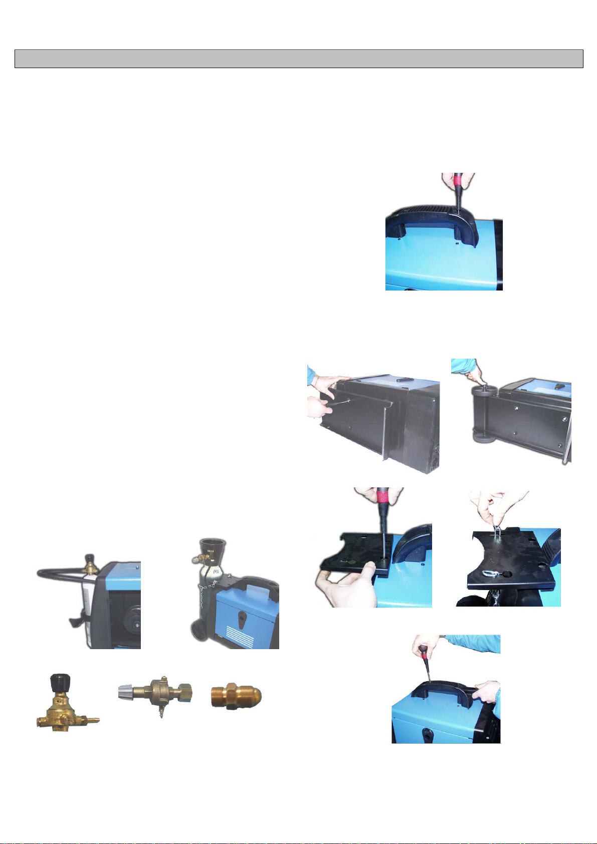
POLISH
OPIS URZĄDZENIA
Spawarki do spawania drutem elektrodowym zmożliwością spawania
rdzeniowym drutem spawa lniczym bez osłony gazów lub w osłonie
gazów stali, stali nierdzewnej ialuminium.
1. INFORMACJE TECHNICZNE
Aby obsługiwać spawania aktu ogólneg o sull'interruttore ON / OFF (1).
Intensywność z wyjściem prądowym spawania regulowany jest za
pomocą dwóch przełączników (2).
Prędkość drutu j est dostosowy w an a pr z ez p okr ętła zmi a n y prędkości (3).
Trzy czerwone diody LED wyśw i etl ac z poz i om u prędkości (4).
Spawacza wyposażony jest ochrona urządzenia, które automatycznie
przerywa dostawy Prąd spawan ia po os iągnięciu wysokich temperatur, w
którym to przypadku należy skręcić jasnożółtym ( 5). Gdy temperatura jest
wystarczająco obniżona i os iągnęły poziom, który umożliwi a praw idłowe
działanie spawacza, żółta lampka wskaźnika zgaśnie. Urządzenie jest
z
a
sil an e aut om at yc z ni e i można wznowić operacje spawania.
2. INS TALACJA
2.1. PO DŁĄCZENIE ELEKTRYCZNE
Spawarka jest wyposažona w kabel zasilający, którego nie naležy
przedłužać. Jeśli z aszłaby potrzeba przedłuženia k abla, nal ežy wym ienić
cały kabel na nowy. Kabel musi posiadać takie same parametry jak
oryginalny kabel, czyli mieć trzy miedziane žyły o przekroju 1,5mm
každa. Przed podłączeniem kabla sieciowego do gniazda naležy się
upewnić, že napięcie zasilające sieci ma taką samą wartość, jaka
widnieje na tabliczce znamionowej spawarki. Naležy się takže up ewnić,
že moc dostarczana przez sieć elektroenergetyczną będzie
wystarczająca do zasilania w pełni obciąžonej spawarki. Sieć
elektroenergetyc zna musi być wyposažona w przewód uziemiający.
Podłączenie wtyczk i
Spawarka jest zasilana z sieci elektroenergetycznej prądu przem ienneg o
230V/50Hz.
Odpowi edn ie prz ewod y są oznaczone kolorami
- przewó d brązowy - faza
- przewó d niebieski - neutralny
- przewó d žółto - zielon y – uziemiający.
2.2. PO DŁĄCZENIE BUTLI ZGAZEM (DLA MODELI WYCIĄGNĄĆ)
Butla z g azem pow inna być umieszczona na platformie znajdującej się z
tyłu spawarki i zabezpieczona łañcuchem.
Naležy się upewnić, že wszystkie połączenia są mocno i pewnie
zamknięte.
Miejsce butelki od 1 kg. gazu (opcjonalnie) z tyłu urządz enia w mi ejscu i
dokręć taśm włączo
butli 5 k g. (Opcj onalnie), po zamont owaniu z estawu kół miejsce butli na
wsparcie i dokręć łańcuchu (Rys.2).
Jeśli korzystasz z CO2, może zaistnieć potrzeba adaptera. Zapytaj
sw ojeg o dealer a.
ne
(rys. 1). Jeżeli maszyna jest wyposażona w gaz z
2
spawania, kabel zwrotny musi być podłączony do odpowiednio
przygotowanego miejsca na sp awanym elemencie. Miejsce podłączenia
powinno być oczyszczone ze smarów, olejów, farby, rdzy oraz innych
zanieczyszczeñ, które mogą wpłynąć ujemnie na charakterystyki
spawania.
W przypadku spawania bez osłony, gazowej przyłącze musi być
podłączone do dodatnich (+) wyjść. Wprzypadku spawania z osłoną,
terminal kablowy musi być podłączony do ujemnych (-) wyjść.
2.4. HANDLE ZGROMADZENIE
Montaż uchwytu, jak pokazano za pomocą śruby.
2.5. ZESTAW KÓŁ (OPCJONALNIE)
Niektór e modele s ą wyposażone w koła zestaw obejmujący: wspier anie
stóp, p iętro, oś, portabom bola, łańcuch załączników, przeciągnij uchwyt,
2 koła i dwa plastikowe kapsle lub blokowania coppiglie. Postępuj
zgodn ie z e sch em at em p on i żej montażu zestawu.
Rys. 1
Regulowania 1
Kg
2.3. PO DŁĄCZENIE PRZEWODU ZWROTNEGO
Spawarka jest wyposažona w zwrotny kabel spawalniczy. W trakcie
Regulowania 5
Kg
Rys. 2
Adapter CO2
Do montażu kół następujących wskazówek:
1. Proszę wprow adz ić w os i otworów w dolnej tyl nej części ciała.
2. Dołącz do kół all' as sal e.
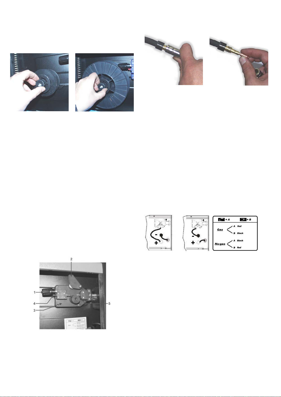
3. Blokowanie kół z coppi glie lub Caps Lock.
4. Zapięcia z przodu wsparcia ze śruby dostarczone Parker Data
5. Bezpieczne dojście przez śrubowania na rozszerzenie obsługi ustalane
na forum.
3. INSTALACJA SZPULI Z DRUTEM SPAWALNICZYM I PALNIKA
3.1. INSTALACJA SZPULI Z DRUTEM SPAWALNICZYM
Urządzenia mogą być wykorzystywane obojętnie bębny ø100 i ø200.
Rolce ma sprzęgła, w celu zachowania drutu dys ku.
13. Cią drutu 6-10 mm poza ws kazówk a. Teraz m aszyna j est gotow a do
rozstrzygnięcia.
ø100
3.2. MECHANIZM PRZESUWU DRUTU
Naležy się upewnić, že rozm iar rowka w rolkach odp owiada średn icy drutu
spawalniczego. Mechanizm obsługuje drut o średnicy 0,6; 0,8 mm, w
przypadku pracy z drutem o średnicy 1 mm naležy zastosować
odpowiednie rolki. Rolki mają wybite z boku oznaczenie obsługiwanej
średnicy dr utu.
W przypadku spawania z gazem osłonowym naležy się zaopatrzyć w
odpowi ednie r olki. W zaležn ości od rod zaju s pawaneg o materi ału nalež y
się zaopatrzyć w rolki z odp ow i ednim rowkiem. R ow ek w k s ztałcie litery V
do drutu stalowego i w kształcie lit ery U w przypadku drutu aluminiow ego.
Do pracy z osłoną gazową, naležy zaopatrzyć się w odpowiednie rolki
oraz reduktorgazowy w celu regulacji ciśnienia gazu.
3.3. ZAK ŁADANIE DRUTU SPAWALNICZEGO
1. Odłączyć wiosną ramię (1) i włączyć go do góry (2), aby przenieść go z
rolki (3). Upewnij się, że porty imiennego stemplowane na bok, aby
średnic a drutu używanyc h.
2. Ostrożnie odłączyć drut z cewki portafilo. Aby uniknąć uciążliwe
sbobinamenti trzymać go w napięc
3. Wyt nij pierwszych 100 m m drutu część lub całość nie idealn ie proste.
4. Włóż drutu w przew odn iku ( 4), p owyżej rolki (3), a następnie włóż ją do
rurki kapilarnej (5).
5. Zamknij lewej premifilo wiosną załadowany. Obróć cewki w celu
dalszego rozluźnić drutu.
6. Gałkę z presj ą drut u jest w p ołowie ciśni enia. Jeśli ciśnieni e jest zbyt
wysokie (ryzyko spłaszczenie drutu), odkręcić pokrętło tak, aby
zmniejszyć ciśnienie. M aġġoranza ciśnienie jest wymagane, jeżeli używa
się drutu od 0,6 m m. J eśli rolk a jazd y kul igi, mus imy zwi ększyć pr esję do
drutu złom u regularni e.
7. Usuń gazu dyszy przewodnikiem i końcówki pochodnie contatto.dalla
pistolet .
8. Umieść przełącznik w położeniu "ON" ( "I").
9. Wyciągnij przew ód w palnik t ak, że jest bardzo w prawo.
10.Press przycisku zasilania palnika i drutu, aż pojawi się na końcu tej
latarka (uważać, aby nie mają broń prz eciwko Tobie lub innym os obom ), a
następnie zwolnij przycis k.
11. Wyłączajsamochód mettendoin pozycji "OFF" ( "O").
12. Wymiepu nk tu kont akt ow eg o el'ugel lo gazu.
i
u do punktu (5).
ø200
3.4. PO DŁĄCZENIE DYSZY SPAWALNICZEJ
Dysza spawalnicza jest podłączona do spawarki i gotowa do užycia.
Ewentualna wymiana dyszy musi być przeprowadzona ze szczególną
ostrožnością i tylko przez wykwalifikowany personel. Aby wymienić
nakładkę stykową naležy ją odkręcić lub wyci ągnąć. Wymienić k oñc ówk ę,
sprawdzić, czy jej rozmiar odpowiada rozmiarowi kabla i wymienić osłonę
gazową. Aby zapewnić właściwe prowadzeni e drutu nalež y zadbać o to,
žeby wszystkie elementy były dopasowane do siebie pod względem
rozmiaru.
4. SPAWANIE
4.1. SPAWANIE CIĄGŁE
Jest to najczęściej wykorzystywanytryb pracy spawarki. W tym trybie
jedyna czynnością, jaką trzeba wykonać, aby rozpocząć spawanie jest
naciśnięcie przycisku na palniku. Aby zakoñczyć spawanie wystarczy
zwolnić nacisk na przycisk.
4.2. CIŚNIENIE GAZU
Ciśnienie gazu zwykle zawiera się w
przepływ na poziomie 6 - 12 litrów na minutę.
Jednak w szczególnych przypadkach ciśnienie gazu p owi nn o być dobrane
do rodzaju wykonywanego spawania.
4.3. SPAWANIE GAZOW E - NO GAS
4.3.1. Gaz - Podłącz latarka do zacisku dodatniego "+" i szczypce do
negatywnych masa "-".
4.3.2. No-Gaz - (tylko dla modeli, które mają tego predyspozycje)
Dokonanie zmiany polaryzacji, podłączyć, a następnie masę szczypce do
pozytywnego "+" i końcowych z pochodnią na negatywne "-".
4.4. GAZOWE I BEZGAZOWE SPAWANIE
MIG - Metal Inert Gas - Spawanie z osłona g a z u o b ojętnego
MAG - Metal Active Gas - Spawa nie w osłonie gazu aktywnego
Te dwie met ody uzup ełniają się, róžnica między nim i tk w i w u žytym gazie
osłonowym. W metodz ie MIG gaz em osłonowym j est argon, w przyp adku
metody MAG takim gazem jest dwutlenek węgla CO. Do spawania
aluminium potrzebna jest osłona argonowa, do spawania stali wystarczy
mieszanka argonu 8 0% i CO 20%.
Osłony z s amego CO možna užyć do spawania želiwa.
5. SPAWANIE
5.1. INFOR MACJE OG Ó LNE
W przypadku spawania na najnižszych nastawach, naležy starać się
utrzymywać jak najkrótszy łuk elektryczny.
Będzie to možliwe, dzięki jaknajkrótszemu dystansowi pomiędzy
palniki em, a spawanym elementem. N aležy takže utr zymywać kąt około
60 stopni pomiędzy palnikiem i spawanym elementem. Długość łuku može
być zwiększana w przypadku spawania przy wyžszych nastawach.
Maksymalna osiągalna długość łuku wynosi 20 mm.
5.2. INFORMACJE DOTYCZĄC
N
iek tór e p rob l e m y p ojaw iaj ące się czasem podczas spawania, są częściej
wynikiem wpływu warunków zewnętrzn ych niž niepraw idłowości w pracy
samej spawarki. Ponižej przedstawiono główne problemy oraz przyczynę
ich pows tawania.
Porowatość
Niewielkie otwory w spawie powstają na skutek przerw w dostawie gazu
osłonowego lub z pow odu z aniec zys zc zeñ g azu. Ab y pozbyć się otworów,
wystar czy oszl ifow ać spaw.
t
akim przedziale, aby zapewnić
E SPAWANIA
Rozpryski
Rozpryski pochodzą od działania łuku elektrycznego. Małe rozpryski są
nie do uniknięcia, ale powinno się dąžyć do minimalizacji zjawiska.
Naležy wybrać odpowiednie nastawy spawarki oraz zapewnić właściwy
gaz i odpowiednie ciśnienie gazu. Naležy takže utrzymywać palnik w
czystości.
Wąska spoina
Jest spow odowana zb yt szybkim pr zesuwaniem palnika lu b niewłaściwie
dobran ym gazem osłonowym.
Spoina bardo niewielkiej grubości lub zbyt szeroka
Jest spowodowana zbyt wolnym przesuwaniem palnika.
Drut spawalniczy ulega przepal eniu
Može to być spowodowane ślizgan iem się rolek mechanizmu podajnika
drutu, poluzowaną lub zniszczoną koñcówka palnika, zbyt bliskim
ustawieniem dyszy względem spawanego materiału lub zbyt wysokimi
nastawami.
Zbyt płytka spoina
Može wynikać ze zbyt szybkiego przesuwania palnika, zbyt niskiego
prądu spawania lub nieprawidłowej prędkości podawania drutu
spawalniczego. Przyczyną može być takže zamieniona polaryzacja.
Naležy zadbać o właści
D
ziurawienie spawanego materiału
we parametry spawania.
Može być spow od ow an e zb yt w ol ny m prz es uw an iem p aln ik a, z byt du žy m
prądem spawania lub ni ew łaściwym prz esuwem drutu.
Duže rozpryski i porowatość
Može być spowodowan e zbyt duž ym dys tans em mied zy dys zą palnika, a
spawanym elementem, zabrudzonym materiałem lub zbyt niskim
ciśnieniem g azu. Naležy p amiętać, že ciśnienie gazu p owinno być takie,
žeby zapewnić przepływ na poziomie 7-8 litrów na minutę. Pomocny w
ustaleniu ciśnienia gazu može być reduktor wyposažony w odpowiedni
manometer.
Niestabilność łuku elektrycznego
Može być spowodowana niewystarczającym prądem spawania,
nieregularnym przesuwem drutu spawalniczego lub niedostateczna
osłona gazową.
Rolki obracają się, mimo to brak
transportu drutu spawalniczego
Drut jest przesuwany z szarpnięciami lub
jest przesuwany w odwrotną stron ę
Brak łuku elektrycznego
Spoina o złych parametrach
Po okresie intensywnego spawania,
spawarka nagle się wyłączyła
USTERKA
1) Zabrudzona droga transportu drutu i/lub
zabrudzona na kładka stykow a
2) Docisk rolek jest zbyt dužy
3) Awaria podajnika drutu
1) Usterka nakładki stykowej
2) Spalona nakładka stykowa
3) Zabrudzony rowek w rolkach dociskowyc
4) Zužyte rolki dociskowe
1) Brak styku między kablem zwrotnym i
spawanym elementem
2) Spięcie miedz y nakładką stykową i
osłona gazową
1) Osłona gazowa zabrudzona odpryskami
2) Niewłaściwa odległość i/lub niewłaściwy
kąt między koñcówką spawalniczą a
spawanym elementem
3) Zbyt mała osłona FLUX w drucie
spawalniczym
4) Zawilgocone spawane elementy
5) Spawane elementy są zardzewiałe
Zadziałał bezpiecznik termiczny spawarki
WYKRYWANIE USTEREK
PRZYCZYNA
OBJAŚNIENIE SYMBOLI
U 0 … (V)
EN 60974 - 1
U 1 … (V/Hz)
I 2 … (A)
I
(A)
1 max
I
… (A) Efektywny prąd zasilający
1 eff
X Cykl pracy
IP21 Stopień ochrony
H Klasa izolacji
Przedmuchać spręžonym powietrzem, w razie
potrzeby wymienić na kładkę stykow
Poluzować docisk rolek
Sprawdzić osłonę prowadnicy drutu
Wymienić nakładkę stykową
Wymienić nakładkę stykową
Oczyścić rolki
Wymienić
Oczyścić rolki
Wyczyścić elementy, w razie potrzeby wymienić
nakładkę stykową lub osłonę
Oczyścić osłonę
Odległość koñca drutu spawalniczego od
spawanego elemen tu musi się zawierać pomiędzy 5,
a 10 mm, a kąt nie može być mniejszy niž 60 stopni
Zmienić drut spawalniczy na właściwy
Osuszyć spawane elementy
Oczyścić spawane elementy z rdzy
Nie wyłączać spawarki, pozwolić jej ostygnąć przez
20 - 30 minut
1 ~
3 ~
Pojedyncze fazy napięcia zmiennego
Trzy fazy napięcia zmienn ego
Wartość znamionowa napięcia bez
obciążenia
Transformer-prostownik
Obowiązująca norma wykonania
Charakterystyka stała
MIG-MA G dr u ty spawalnicze pasz y
Wartości znamionowe napięcia
zasilania i częstotliwości
Symbol i jednostka prądu spawania
Wartość znamionowa prądu zasilania
Symbol spawarek, które mogą być
używane w środowisku ze
zwiększonym niebezpieczeństwem
porażenia prądem el ekt r yc z nym
Symbol odniesienia do instrukcji
bezpieczeństwa
USUNIĘCIE USTERKI
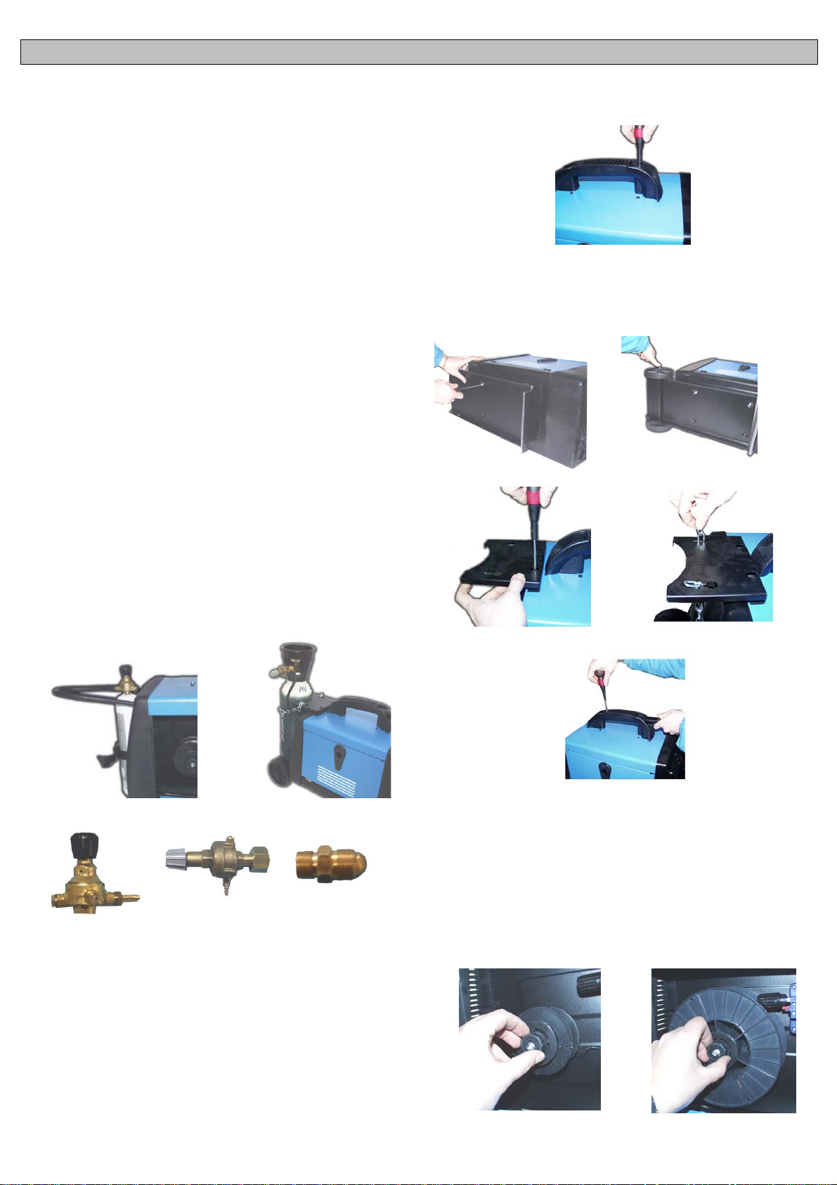
NEDERLANDS
ALGEMENE OMSCHRIJVING
Draadnaadlasapparaten met de mogelijkheid tot lassen van kerndraad
zonder gas of met gas voor het lassen van staal, roestvrijstaal en
aluminium.
1. TECHNISCHE INFORMATIE OVER HET LASAPPARAAT
Voor d e exploitatie van het lassen optreden sull'interruttore algemene ON
/ OFF (1) .
De intensiteit van de lasstroom wordt uitgang is instelbaar door middel
van tw ee schakelaars (2).
De snelheid van de draad wordt aangepast door de knop van de variatie
van de snelheid (3). Drie rode LED's weergeven van het niveau van de
snelheid (4).
De lasser is uitgerust met een thermische beveiliging apparaat dat
autom atisc h wordt d e lev ering v an lasst room wordt w anneer zij t ot hoge
temp erat ur en, in welk g eval u e en licht geel (5) . W ann eer d e tem p er atu ur
voldoende is verlaagd en het niveau bereikt dat dat de goede werking
van de lasser, het gele lampje gaat uit. Het apparaat wordt gevoed
autom at is ch en u ku nt herv at t en l ass en.
2. HET APPARAAT INSTALLEREN
2.1. HET APPARAAT OP HET ST R OOM NE T AANS LU ITE N
Het apparaat wordt gelever d met een eig en voedingkabel die niet mag
worden verlengd; indien dit toch noodzakelijk is, dient men een kabel met
dezelf d e diam eter te gebr uiken als de kab el di e bij het appar aat h oor t.
Voord at u de st ekk er van het las app araat in h et st opcont act steekt , di ent
u te controleren of de spanning van het stroomnet dezelfde is als de
spann ing v an het appar aat en of h et v ermog en v olst aat om het appar aat
bij volle b elastin g te voeden; controleer ook of de voedin gleid ing corr ect
is geaard.
De voed ing sp anning
Bedr aagt de voedings panning 230 V.
2.2. HET APPARAAT AARDEN (VOOR MODELLEN DIE)
De gascilinder moet worden geplaatst in de deur-cilinder in de
achter zij de van d e mach ine di e op het p latf orm. I n aans luiti ng op de tank
om te contr ol er en of all e aan val l en z ij n erg strak.
Plaats de fles uit 1kg. g as (option eel) op de acht erkant v an de machin e
in de plaats en draai de riemen inbegrepen (fig. 1). Als de mach ine is
uitger ust met een g asfl es uit 5Kg. (Option eel), n a de montag e van de kit
wielen plaats de cilinder op de steun en draai de keten (Fig.2).
Als je g ebru ik maakt van de C O2-uit stoot , moet u mogel ijk een adap ter.
Vraag uw deal er.
2.4. HANDLE VERGADERING
De montage van de hendel zoals afgebeeld met behulp van de
schroeven.
2.5. MONTAGE VAN HET WIEL-KIT (OPTIONEEL)
Sommige modellen zijn uitgerust met een wiel-kit bestaat uit:
ondersteuning mond, vloer, as, portabombola, ketting attachments,
sleept handvat, 2 wielen en twee plastic dopjes of vergrendeling
copp iglie. V olg de onderst aande schema voor de montage-kit.
Fig. 2
Fig. 1
Regelen 1 Kg Regelen 5 Kg Adapter CO2
2.3. HET APPARAAT AARDEN
De machine wordt geleverd met een aardingskabel met een aardk lem.
Controleer of het contact tussen de klem en het te lassen voorwerp
perfect is. Reinig de contacten zodat er geen vet, roest of andere
onzuiverheden op blijven zitten. Een contact dat niet perfect is,
vermindert de lascapac iteit en kan dus een onbevredigend lasresu ltaat
tot gevolg hebben. Het uiteinde van de aardklem moet in de uitgang van
de pos itiev e pool (+) worden gest oken voor het lass en zon der g as; voor
lassen met gas moet deze in de uitgang van de negatieve pool (-)
word en gestoken.
Voor d e mont age van w ielen volg de volgende instruc ties:
1. Geef de as in de gaten op de bodem achterzijde van het lichaam.
2. Beves ti g de w iel en all ' assale.
3. Blokkeer de wielen met de coppiglie of met caps lock.
4. Bevestig de voorste steun met de bijgeleverde schroeven parker
datum.
5. Zet de hendel van schroeven op de uitbreiding vaste greep op het
forum.
3. DE DRAADSPOEL EN DE LASTOORTS MONTEREN
3.1. DE SPOEL MONTEREN
De machines kunnen worden gebruikt onverschillig rollen ø100 en ø200.
De cilin d er heef t een k opp eli n g, om z o de dr aad rij den.
ø100
ø200

3.2. DE DRAADAAN VOERMOTOR
Contr ole er of de gr oef i n het rol letje dat de dr aad aan vo ert ov er eens temt
met de dikte van de gebruikte draad. De machines zijn uitgerust met
rollet jes v oor dr aden van Ø 0, 6 en Ø 0,8. O p de zij kant van h et rollet j e is
de diameter afgedrukt van de draad waarvoor het rolletje kan worden
gebr uikt. Zijn uit gerust met roll etjes in een leg erin g die gesch ikt is voor
lassen m et een gevulde draad zonder gasbescherming. Om draad met
gasbescherming te lassen, dient het rolletje in de aanvoerunit te worden
vervan gen door een rolletje met een V -vor mige groef v oor staald raad
en een U-vormige groef voor aluminiumdraad. Vraag deze rolletjes en
het reduc eerventiel aan uw verkoper of rechtstreeks aan de producent
als u het lasapparaat met gasbesch erming wenst te gebruiken.
4.3. DE DRAAD MONTEREN
1. Ontk opp el de len t e arm (1) en dr aai het volu me om hoog (2) om het t e
verplaatsen uit de buurt van de rol (3). Zorg ervoor dat de havens roll
stemp el op d e zij k ant om de diam eter van de dr aad w or d en g ebr u ikt .
2. Zorgvuldig koppelt u de draad van de spoel portafilo. Om te
voorkomen dat vervelend sbobinamenti houd hem in spanning op het
punt (5).
3. Snijd de eerste 100 mm van de kabel of het gehele onderdeel niet
perfect recht.
4. Steek de draad in de gids (4), boven de roll (3) en vervolgens plaatst u
deze in de capillaire buis (5).
5. Sluit de linker premifilo veergedreven. Draai de rollen om verder los
van de dr aad.
6. De knop v an de druk van d e draad is ingest eld op de helft dr uk. Als
het druk is overdrev en (risic o van de afvl akking van d e draad), dr aai de
knop, zodat de vermindering van de druk. Maġġoran za druk is nodig al s
u de draad van 0,6 m m. Als de rollen rijden slee, moeten w e de druk
totdat de draad rest anten regelmatig.
7. Verwijder het gas straalpijp gids en het topje van de fakkel
contatto.d all a pistool.
8. Zet de schakelaar in de stand "ON" ( "I").
9. Trek het snoer van de fakkel, zodat het is zeer goed.
10.Pr ess knop fakk el en diervoed ers de draad t otdat het aan h et einde
van de fakkel (oppassen niet te streven het geweer tegen u of andere
person en) , d an l aat d e kn op los.
11. Schakel automatisch instelling in positie "OFF" ( "O").
12. Verv an g het contactpu nt el' ug el l o gas .
13. Snij den draad 6.10 mm buit en de tip. Nu d e machine is kl aar om t e
bezinken.
3.4. DE VL AM STRAAL AANSL U I TE N
De glasblazerslamp reeds gemonteerd en aangesloten en dus klaar
voor gebruik. Een eventuele vervanging dient uiterst zorgvuldig te
worden gedaan, liefst door een ervaren technicus. Om het
gasgeleiderspunt te vervangen, dient deze slechts te worden
losgeschroefd of naar buiten te worden getrokken. Het gasgeleiderspunt
dient t e worden ver wijderd telk ens als de dra admond w ordt v ervang en.
De afmetingen van deze draadmond dient te passen bij de draad
waarmee men last. Houd het g asgeleiderspunt steeds schoon.
4. DE LASMETHODES
4.1. CONTINU LASSEN
Dit is het m eest g ebru ikt e syst eem. Z odr a de mac hin e klaar st aat, hoeft u
de glasblazerslamp slecht s in te drukk en om te b eginnen met lassen. Om
te stopp en l aat u een v ou di g w eg de kn op l os.
4.2. DE GASDRUK
De gasdruk moet zodanig worden afgesteld dat een hoeveelheid gas van
6 tot 12 liter wordt toegevoer d.
4.3. GAS - NO GAS LASSEN
4.3.1. Ga s - K lem v an d e glas bl azers l amp in de p os itiev e u itg ang “+” e n
aardklem in de negatieve uitgang “-”.
4.3.2. No-Gas - (Alleen geldig voor de modellen die hiervoor zijn
uitgerust); aardklem in de positieve aansluiting “+” en klem van de
glasblazerslamp in de negatieve aansluiting “-”.
4.4. MIG - MAG LASSEN
A) M I G = M etal Inert Gas
B) M AG = Metal Active Gas
Beide werkmethodes zijn perfect gelijkwaardig; alleen het type gas
verschilt.
In geval A gebruikt men ARGON (inert gas)
In geval B gebr uikt men CO
(reactief gas)
2
Om alum inium- of in oxleger ingen te las sen dient men zuiv er ARGON te
gebr uiken, of event ueel een mengs el dat voor 80% uit ARGO N bestaat
en 20% CO
Uitsluitend CO
.
2
gebruiken is gesc hikt voor het lass en van koolstofstaal
2
(ijzer).
5. GIDS VOOR HET LASSEN
5.1. ALGEMEEN VOORSCHRIFT
Bij een min imum afstell ing hoort een klein e boogl engt e. Die verk rijgt men
door d e glasblaz ers lamp zo dicht mogel ijk bij het t e lassen wer kstuk te
houden, in een hoek van circa 60 graden. De boog kan langer worden
gemaakt naargelang meer str oom wordt toegevoerd, tot een maximu m
booglengte van circa 20mm.
5.2. RAADGEVINGEN VAN ALGEMENE AARD
Af en toe kan h et las sen kleine d ef ecten vert onen . Deze d efecte n kunn en
snel worden verholpen als men rekening houdt met de volgende
raadgevingen:
- Poreusheid
Kleine gaatjes in de las, die lijken op de gaatjes in chocolade
bijvoorbeeld, kunnen worden veroorzaakt door de gastoevoer of
zelfs door minuscule onzuiverheden. Meestal wordt dan de las
verwijderd om opnieuw te beginnen. Voordat men opnieuw begint,
dient m en ec ht er d e gas t oev o er t e cont r ol er en (c irca 8 liter/ mi nuut ) ,
het te lassen oppervlak zeer goed te reinigen en de
glasblazerslamp correct te buigen tijdens het las sen.
- Spatten
Dit zijn kleine druppels gesmolten metaal die uit de lastoorts komen.
Kleine hoeveelheden spatten zijn onvermijdelijk, maar de spatten
kunn en tot een minimu m worden herlei d door de s trooms terkt e en
de gastoevoer goed af te stellen en de glasblazerslamp altijd
sch oon te houden.
- Een te smalle en te bolle lasnaad
Dit wordt veroorzaakt door een te snelle beweging van de
glasblazerslamp of door een niet goed afgestelde gastoevoer.
-Een te brede en te dikke lasnaad
Dit kan worden veroorzaakt door een te traag bewegende
glasb l az ers lam p.
-De ac hterkant van de draad is verbra nd
Dit kan word en ver oorz aakt d oor een dr aad die t e lang zaam wordt
aangev oerd; door een te losse of verslet en “liner”punt; de slechte
kwaliteit van de draad, een te kleine opening van de
gasg elei d ers p u itm on d of een t e hoge st r oom sterkt e.
-Te weinig penetratievermogen
Dit kan lig gen aan een t e sn ell e bew egi ng v an d e gl asbl az ersl amp,
aan een te lage stroomsterkte, een niet correcte draadtoevoer,
verwisselde polen, ongelijke en onvoldoende afstand tussen de
twee aan elkaar te lassen werkstukranden. Verbeter de
lasparameters en de voorbereiding van d e te lassen werkstukk en.

-Door gebrand werkstuk
Dit kan afhangen van een te langzame beweging van de
glasblazerslamp, te hoge stroomsterkte of een niet correcte
draadaanvoer.
-Te veel spatten en poreusheid.
Dit kan liggen aan een te grote afstand tussen de
gasgeleiderspuitmond en het werkstuk; vuil op het werkstuk; te
weinig gastoevoer of te lage stroomsterkte. De parameters dienen
te word en gec ontr oleer d met het oog op het f eit dat d e gast oevoer
niet minder mag bedragen dan 7-8 liter/min. en dat de
lasstroomsterkte aangepast dient te zijn aan de diameter van de
draad die men gebruikt. Het verdient aanbeveling een
drukreduceerventiel op de in- en de uitgang van het
gastoevoersysteem aan te brengen. Op de manometer op de
uitgang kan men ook het toevoervermogen uitgedrukt in liters
aflezen .
-Instabiele lasboog
Dit kan worden veroorzaakt door een onvoldoende lasspanning;
een onregelmatige draadaanvoer, onvoldoende beschermgas.
DE BETE KENIS VAN OPSCHRI FTEN EN SYMBOLEN
1 ~
Eenfase wisselspanning
Constant kenmerk
MIG-MA G l assen
U 1 … (V/Hz)
I 2 … (A) Conventionele lasstroom
I
(A) Maximum verbruiksstroom van de lijn
1 max
I
… (A) Effectieve huidige geleverd
1 eff
X Verhouding intermittentie
IP21
H Klasse isolering transformator.
Wisselspanning en
voedingsfrequentie van de
lasmachine
Dit symbool betekent de
beschermingsklassevan de
lasapparatuur.
Lasmachine geschikt voor gebruik in
een ruimte met vermeerderd risico
voor elektroshoc ks .
3 ~
U 0 … (V) Maximum spanning leeg
EN 60974-1
DEFECT
De draad wordt niet aangevoerd als het
aandrijfwiel draait
Draadaanvoer met schokken of
tussenpozen
Boog uitgedoof d
Pore uze lasnaa d
De machine stopt plots na langdurig
lassen
Drief as en wisselspann in g
Transformator-gelijkrichter
Standaardmaat van refereren
DEFECTEN OPSROREN
OORZAAK
1) Er zit vuil op de punt van de
draadgeleider
2) De wrijving van de afwi kkelhas pel is te
hoog
3) Defecte glasblazerslamp
1) Contact defect
2) Verbrande punten in de co nta ct mon d
3) Vuil in de aandrijfwielgr o ef
4) Groef op het aandrijfwiel te diep
1) Slecht contact tussen de aardeklem en
het werkstuk
2) Kortsluiting tussen contactmond en
gasgeleiderpunt
1) Geen gasbescherming veroorzaakt door
kor stvorming in de gasgeleidermond
2) Verkeerde afstand of hoek van de
glasblazerslamp
3) Te weining gas
4) Vochtige werkstukken
5) Werkstukken met veel roest
1) De machine is oververhit door te veel
lassen
Symbol odniesienia do instrukcji
bezpieczeństwa
Lucht biazen
Losmaken
Controleer de draadgeleidernuls
Vervagen
Vervagen
Reinigen
Vervagen
De klem sluite n en controleren
Reinigen of vervangen contactmond en
gasgeleider
Korsten verwijderen of vervagen
De afstand tussen de gl as bl azerslamp en
het werkst u k moet 5 – 10 mm bedrag en, de
hoek niet minder dan 60 t.o.v. het werkstuk
Verhoog de gastoev oer .
Drogen met een hete-luchtpistool of een
ander middel
Rei nig de werkstukken
L
t de machi ne mi n st ens 20-30 minuten
aa
afkoelen
OPLOSSING

РУССКИЙ
ОБЩЕЕ ОПИСАНИЕ
Сварочные аппараты MIG предназначены для сварки с
использованием порошковой электродной проволоки (без
применения защитного газа) или для сварки стали, нержавеющей
стали и алюминия (в среде защитного газа).
1. ТЕХНИЧЕСКАЯ ИНФОРМАЦИЯ
Данный сварочный аппарат приводится в действие с помощью
основного выключателя (1). Величина сварочного тока определяется
значением, устанавливаемым с помощью двух переключателей (2).
Скорость по
датчика (3). Три красных светодиода указывают на выбранную
скорость (4).
Данный сварочный аппарат оснащен устройством термозащиты,
которое при значительном перегреве приводится в действие
автоматически (5). При срабатывании термозащиты загорается
желтый светодиод. После охлаждения аппарата до необходимой
температуры светодиод погаснет автоматически и аппарат будет
готов к работе.
2. ПОДГОТОВКА АППАРАТА К РА
2.1. ПОДКЛЮЧЕНИЕ К ИСТОЧНИКУ ПИТАНИЯ
Сварочный аппарат ос нащен оригинальным кабелем. Настоятельно
рекомендуем Вам не пользоваться удлинителями. Если все же
возникает необходимость использовать более длинный кабель
питания, то используйте удлинители с соответствующим сечением
провода.
Убедитесь, что напряжение сети соответствует напряжению питания
аппарата, а также в достаточном заземлении.
Значение напряжения
Необходимое з
Вольт.
2.2. УСТАНОВКА ГАЗОВОГО БАЛЛОНА(ТОЛЬКО НА
ОПРЕДЕЛЕННЫХ МОДЕЛЯХ)
Установите баллон с защитным газом в вертикальном положении на
специально предназначенный держатель с обратной стороны
сварочного аппарата и закрепите баллон цепью. Для остальных
моделей баллон должен быть размещен на опорной платформе.
Убедитесь, что баллон надежно зафиксирован.
Установите ки
дополнительно) с задней стороны аппарата и закрепите ремень
(рис. 1). Если аппар ат оборудован пятикилограммовым баллоном,
установите баллон с задней части аппарата и закрепите цепью (рис.
2).
При использовании двууглекислого газа СО
необходимость использовать газовый нагреватель. Проверьте
герметичность соединений.
д
ачи сварочной проволоки регулируется кнопкой
ОТЕ
Б
ачение напряжения для данных аппаратов - 230
н
л
ограммовый газовый баллон (баллон приобретается
может возникнуть
2
2.4. УСТАНОВКА РУКОЯТКИ
Установите рукоятку с помощью прилагаемых винтов.
2.5. УСТАНОВКА КОЛЕС (ДОПОЛНИТЕЛЬНО)
Некоторые модели оснащены набором колес, состоящим, помимо
колес, из опоры, стойки и держателя для газового баллона, оси,
удлинителя рукоятки, колпачков. Инструкции по установке колес
приведены на рисунках.
Рис. 1
Рис. 2
Редуктор 1 Kg Редуктор 5 Kg Переходника
CO
2.3. ВЫПОЛНЕНИЕ ЗАЗЕМЛЕНИЯ
В комплект поставки входит заземленный кабель, соединенный с
зажимом. Заземленный зажим должен касаться обрабатываемого
изделия. Во время работы должен обеспечиваться хороший контакт
между зажимом и заготовкой, т.к. недостаточный контакт может
ухудшить условия работы и снизить качество сварочного шва. При
осуществлении безгазовой сварки соедините зажим сварочного
пистолета с положительной кле
газовой сварки – с отрицательной (-).
м
мой (+), а при осуществлении
2
3. УСТАНОВКА КАТУШКИ С ПРОВОЛОКОЙ И СВАРОЧНОГО
ПИСТОЛЕТА
3.1. УСТАНОВКА КАТУШКИ С ПРОВОЛОКОЙ
Для данных моделей можно использовать катушки диаметром 100
и 200 мм. Барабан катушки оснащен специальной сцепкой для
обеспечения постоянной подачи проволоки.
ø100
3.2. ЭЛЕКТРОДВИГАТЕЛЬ ПРИВОДА ПОДАЧИ ПРОВОЛОКИ
Убедитесь в том, что размер отверстия приводного ролика
соответствует размеру проволоки. Необходимый диаметр
ø200

проволоки указывается на ролике сбоку. Данные аппараты также
оснащ ены роликами, подходящими для использования порошковой
электродной проволоки для осуществления безгазовой сварки.
При проведении сварки в среде защитного газа необходимо
установить ролик подающего механизма V-образной формы для
стальной проволоки и U-образной формы для алюминиевой
проволоки. Ролики данного типа можно приобрести у Ва
п
родавца.
3.3. ПОДАЧА ПРОВОЛОКИ В СВАРОЧНЫЙ ПИСТОЛЕТ
1. Откройте зажим механизма подачи (1) и отверните приводные
ролики (2 и 3). Убедитесь, что отверстие прижимного ролика
соответствует размеру используемой проволоки.
2. Аккуратно отделите конец проволоки от катушки. Для того
чтобы избежать разматывания катушки, на проволоку должно
оказываться равномерное давление.
3. Отрежьте конец проволоки длиной приблизительно 10 см.
4.
роденьте проволоку через отверстие (4) прижимного ролика
П
(3) в направляющую (5).
5. Опустите зажим на проволоку и заверните прижимной винт (2).
При необходимости поверните катушку против часовой стрелки,
чтобы удалить зазор.
6. Давление, оказываемое на проволоку приводными роликами,
регулируется с помощью прижимного винта. При чрезмерной
подаче проволоки поверните прижимной винт против часовой
стрелки, таким об
проволоки. При использовании проволоки 0,6 мм может
возникнуть необходимость уменьшить давление. Если при
подаче проволоки приводной ролик соскальзывает, давление
должно быть увеличено.
7. Снимите сопло и зажим со сварочного пистолета.
8. Включите аппарат “ON” (I).
9. Закрепите провод сварочного пистолета.
10. Нажмите на кнопку пуска, чтобы появилась проволока. (Не
направляйте сварочный пистолет на себя или окружающих во
время работы). Отпустите кнопку после появления проволоки.
11. Выключите аппарат “OFF” (“О”).
12. Установите контакт и сопло.
13. Отрежьте конец проволоки (6 – 10 мм) на ко
Аппарат готов к работе.
р
азом, можно избежать искривления
нце ко
шего
нтакта.
3.4. УСТАНОВКА СВАРОЧНОГО ПИСТОЛЕТА
У данных моделей сварочный пистолет уже подсоединен к аппарату
и готов к использованию. Замена сварочного пистолета должна
осуществляться только квалифицированным специалистом. Для
замены контактов открутите их и снимите. Замените контакт,
проверив, что он подходит к сварочной проволоке, которую Вы
используете. Установите сопло. Для хорошей подачи сварочной
проволоки оч
соответствующие ее диаметру и материалу. Содержите контакты в
чистоте.
ень ва
жно использовать комплектующие,
4. РЕЖИМЫ СВАРКИ
4.1. СВАРКА С НЕПРЕРЫВНОЙ ПОДАЧЕЙ ПРОВОЛОКИ
При использовании данного режима аппарат работает
непрерывно. Для начала работы необходимо нажать на кнопку
сварочного пистолета, для окончания работы необходимо
отпустить кнопку.
4.2. ДАВЛЕНИЕ ГАЗА
Давление газа должно соответствовать значению от 6 до 12
ли
ров в минуту. Давление определяется с помощью манометра.
т
Каждый пользователь может определить самостоятельно, какое
давление наиболее подходит для типа сварки, которую он
выполняет.
4.3. ГАЗОВАЯ – БЕЗГ АЗОВАЯ СВАРКА
4.3.1. Газовая сварка - При газовой сварке зажим сварочного
пистолета необходимо приложить к положительной клемме «+», а
заземленный зажим – к отрицательной клемме «-».
4.3.2. Безгазовая сварка (т
Заземленный зажим надо приложить к положительной клемме «+»,
а зажим сварочного пистолета к отрицательной «-».
4.4. СВАРКА В РЕЖИМАХ MIG – MAG
а) MIG = сварка плавящимся электродом в среде инертного газа
б) MAG = сварка плавящимся электродом в среде активного газа
Эти два режима абсолютно идентичны, разницу составляет лишь
тип газа, который Вы используете. В первом случае необходимо
использовать аргон (инертный газ). Во втором случае необходимо
использовать двууглекислый газ СО
Для сварки алюминиевых сплавов необходим аргон (100%), для
сварки стали – газовая смесь из аргона (80%) и двууглекислого
газа (20%). Для сварки железа необходимо использовать только
двууглекислый газ.
5. ИНСТРУКЦИИ ПО ПРОВЕДЕНИЮ СВАРКИ
5.1. ОБЩИЕ ПРАВИЛА
При ос ущ ествлении сварки с использованием низкого значения
тока, необходимо, чтобы дуга была как можно короче. Для этого
прижмите на
можно ближе к свариваемой детали. При использовании высокого
значения тока можно увеличить длину дуги до 20 мм.
5.2. ОБЩИЕ РЕКОМЕНДАЦИИ
Часто причиной дефектов сварочного шва является не
неисправность сварочного аппарата, а внешние воздействия. Для
избежания неполадок обратите внимание на следующие
рекомендации:
• Сварочный шов пористый
Причиной п
подачи защитного газа или попадание инородных тел. Для
устранения этой неисправности необходимо зачистить сварочный
шов.
Прежде чем проводить сварку, убедитесь в достаточной подаче
газа (примерно 8 литров в минуту). Содержите рабочее место в
порядке. Во время сварки наклоняйте пистолет.
• Брызги
Представляют собой частицы расплавленного ме
от
скакивающие от сварочной дуги. Появление брызг неизбежно, но
их количество можно уменьшить, правильно установив сварочный
ток и поток газа. Содержите сварочный пистолет в чистоте.
• Узкий округлый сварочный шов
Образуется при слишком быстром продвижении сварочного
пистолета или неправильном потоке газа.
• Широкий сварочный шов
Образуется при слишком медленном продвижении сварочного
пи
с
толета.
• Обгорание проволоки
Происходит при соскальзывании подаваемой проволоки,
повреждении контакта, плохом качестве проволоки, при слишком
близком прижимании сопла к обрабатываемому изделию или
слишком высоком напряжении.
• Маленькая глубина провара
Причиной может быть слишком быстрое продвижение сварочного
пистолета, низкое напряжение, неправильный сварочный ток,
неправильная полярность. Убедитесь в правильности
нечник сварочного пистолета под углом 60° как
ко
стости сварочного шва может быть нарушение
ори
олько для оп
(активный газ).
2
ределенных моделей) -
талла,
установленных параметров и хорошей подготовке сварочной
заготовки.
• Проваривание обрабатываемого изделия
Причиной может быть слишком медленное передвижение
сварочного пистолета, слишком высокое значение сварочного тока
или неправильная скорость подачи проволоки.
• Пористый сварочный шов и образование большого
количества брызг
Причиной может быть недостаточный газовый поток, загрязнения на
обрабатываемой заготовке или расположение сопла на слишком
большом расстоянии от обрабатываемого изделия. Обратите
внимание на то, что поток газа должен быть не менее 7 – 8 литров в
минуту, а сварочный ток соответствовать типу используемой
проволоки. Рекомендуем использовать редуктор. По манометру Вы
можете определить расход газа в литрах.
• Нестабильная сварочная дуга
Причиной может быть недостаточное значение входного
напряжения, не
правильно установленная скорость подачи
проволоки, недостаточное количество защитного газа.
ОПИСАНИЕ ЗНАКОВ И СИМВОЛОВ
1 ~
3 ~
U 0 … (V)
Однофазное напряжение
(переменный ток)
Трехфазное напряжение
(переменный ток)
Номинальное напряжение
холостого хода
EN 60974-1
U 1 … (V/Hz)
I 2 … (A) Сварочный ток
I
(A)
1 max
I
… (A)
1 eff
X Цикл работы
IP21 Класс защиты
H Тип изоляции
Европейская норма
Постоянные характеристики
Сварка MIG -MAG
Номинальное входное
напряжение и частота
Максимальное значение
потребляемого тока
Действующее значение
потребляемого тока
Сварочное оборудование,
подходящее для использования в
условиях с высоким риском
поражения электрическим током
Символы безопасности
Трансформатор-выпрямитель
УСТРАНЕНИЕ НЕИСПРАВНОСТЕЙ
Неисправность Причина Способ устранения
Непоступление проволоки при
повороте ролика
Нерегулярное поступление
проволоки
Отсутствие дуги 1) Плохой контакт между заземленным
Сварочный шов пористый 1) Попадание брызг в сопло
С
варочный аппарат внезапно
прекращает работу после
длительного использования
1) Загрязнение сопла или контакта
2) Фрикционный тормоз в штативе затянут
слишком сильно
3) Неисправность сварочного пистолета
1) Повреждение контакта
2) Обоженный контакт
3) Засорение канавки приводного ролика
4) Износ ро
зажимом и обрабатываемым изделием
2) Короткое замыкание между контактом и
соплом
2) Неправильное расстояние между
сварочным пистолетом и/ ил
правильный угол наклона по отношению
не
к обрабатываемому изделию
3) Слишком маленький поток газа
4) Влажное обрабатываемое изделие
5) Ржавчина на обрабатываемом изделии
1) Перегрев сварочного аппарата из-за
превышения рабочего цикла
лика
Продуйте сжатым воздухом,
замените контакт
Ослабьте тормоз
Проверьте подачу проволоки
мените контакт
За
Замените контакт
Зачистите канавку
Замените ролик
Закрепите зажим и проверьте
соединение
Прочистите, замените контакт и/
или сопло
Прочистите сопло
Расстояние между контактом и
обрабатываемым изделием должно
и
составлять 5 – 10 мм. Угол наклона
должен быть 60 °
Увеличьте поток газа
Высушите с помощью установки
горячего воздуха
Очистите от рж
Не выключайте аппарат. Подождите
в течение 20/30 минут, пока он
остынет
авчины
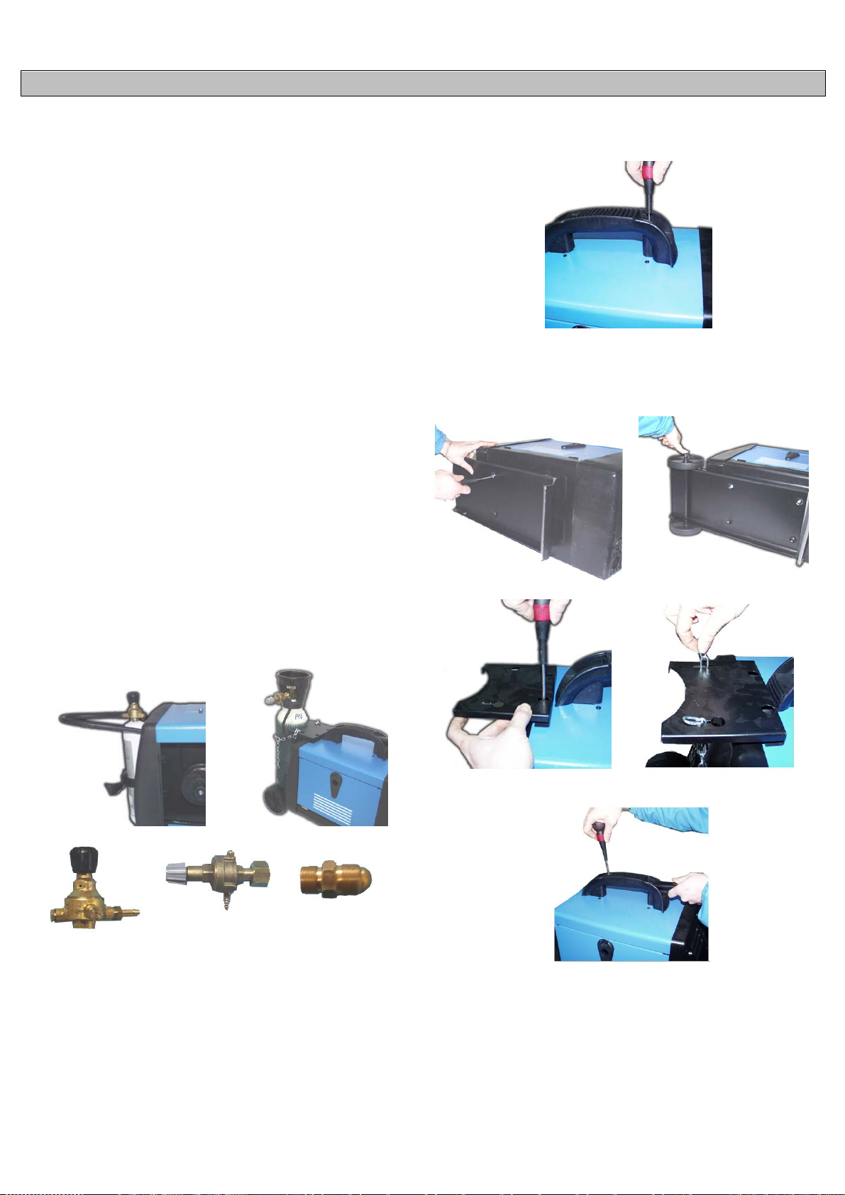
DANISH
BESKRIVELSE AF APPARATET
MIG svejsere, som kan svejse flux kernehus gasless trådbunden eller
med gas til svejsning ofmild stål, rustfrit stål og aluminium.
1. SVEJSEAPPARATETS TEKNISKE INFORMATION
Til at driv e svejser ti l at handle på omskifteren ON / OFF (1).
Intens itet en af svej sn ing nu vær end e prod ukt ion er jus t erbar v ed hj ælp af
to kontakter (2).
Hastigheden af wiren er tilpasset ved knop af variation af hastighed (3).
Tre røde lysdioder vist niveau af hastighed (4).
Den svejser er udstyret med en termisk beskyttelse anordning, der
autom atisk afbr yder fors yningen af el ektrisk s trøm til sv ejs ning, når det
når op på høje tem peratur er, i hvilk et tilfæld e du tænder et lys gul (5) .
Når temperaturen er tilstrækkelig sænkes og nåede det niveau, der
tillader den korrekte funktion af svejser, den gule indikatorlampen
slukk es. Maskin en er fodret au tomatisk og du kan genopt age svejs ning
operationer.
2. INSTALLATION
2.1. ELTILSLUTNING
Maskinen er forsynet med et specifikt strømforsyningskabel, der ikke bør
tilsluttes forlængerledning. Hvis dette skulle være nødvendigt, skal der
anven des en forlængerledning med samme tværsn it som maskinens.
Før svejsemaskinen tilsluttes stikkonatakten, skal det sikres, at
spændingen svarer til maskinens, og at effekten er tilstrækkelig til at
forsyne maskinen med fuld belastning. Sørg endvidere for, at
strømforsyningsanlægget er forsynet med et passende
jordforbindelsessystem.
Spænd ing sf or syning
Er spændingsforsyningen på 230 V.
2.2. TILSLUTNING TIL JORDFORBINDELSE (FOR MODELLER
DRAGES
Gascylinderens skal placeres i dør-cylinder i den bageste del af
maskinen er gengivet på perronen. I forbindelse med tanken kontrollere,
at alle angr eb er meg et stram.
Sted flasken fra 1kg. gas (ekstraudstyr) på bagsiden af maskinen på
plads og stramme stropperne inkluderet (figur 1). Hvis maskinen er
udstyret med en gasflaske fra 5 kg. (Ekstraudstyr), efter montering af
sættet hjul sted cylinderen på st øtte og stramme kæ den (Fig.2).
2.4. HÅNDTERE FORSAMLING
Mount ing håndtaget som vist ved hjæ lp af skr uer.
2.5. HJULMONTERING KIT (VALGFRIT))
Nogle modeller er udstyret med et hjul kit bestående af: støtte mund-,
gulv-, aksel, portabombola, kæde vedhæftede filer, skal du trække
håndtaget, 2 hjul og to plastkapsler eller låsning coppiglie. Følg
diagrammet n edenfor for Monteringssæt.
Fig. 1
Regulere 1 Kg Regulere 5 Kg Adapter CO2
2.3. TILSLUTNING TIL JORDFORBINDELSE
Maskinen er fosynet med et jordforbindelseskabel, der er forbundet med
en klem m e. K ontr oll ér, at der er k orrekt k ont akt m ell em k lemm en og de t
emne, der skal svejses. Rengør omhyggeligt kontakterne, så der ikke er
tilstedeværelse af fedt, rust eller urenheder. En mangelfuld kontakt
reducerer svejsekapaciteten og kan dermed være skyld i en
utilfredsstillende svejsning. Jordklemmens pol skal indsættes i den
positive pol-udgang (+) for svejsning uden gas. For svejsning med gas,
skal den derimod indsættes i den negative pol-udgang (-).
Fig. 2
Til monterin g hjul fø lge følgende instruktioner:
1. Angiv aksel i huller n e på den n ed er ste bagest e del af kroppen.
2. Påsæt ni n g af hj ul all' assale.
3. Blokere hjulene med coppiglie eller med Caps Lock.
4. Fastgør forsiden støtte med skruer leveres Parker Dato
5. Secure håndtaget ved skruning om udvidelse håndtere fast på
forummet.
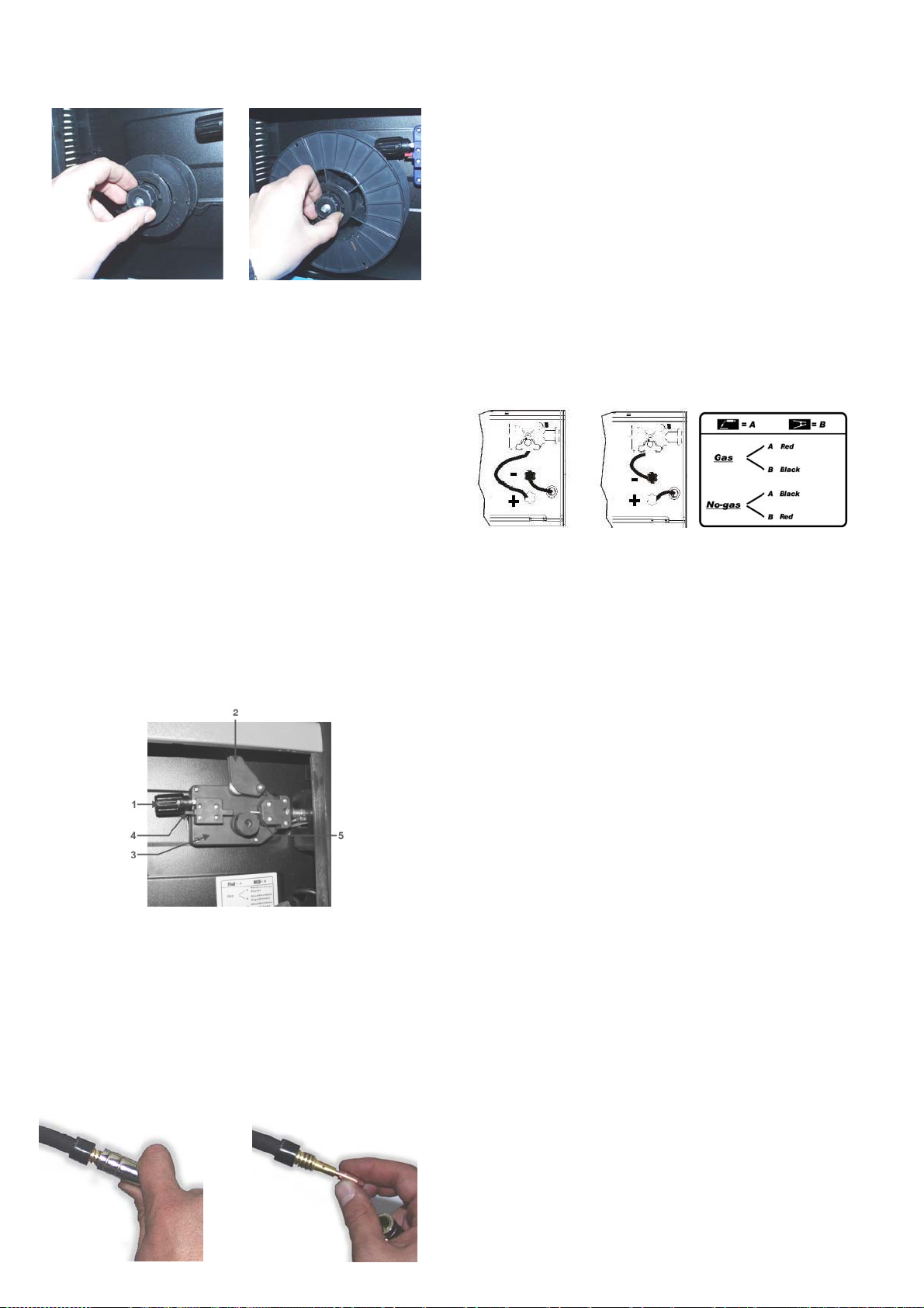
3. MONTERING AF TRÅDSPOLE OG BRÆNDER
3.1. MONT ER ING AF SPOL E
Maskinerne kan bruges indifferently ruller ø100 og ø200. Rullens har en
kobling, for at holde t rådbunden drev.
ø100
3.2. MOTOR FOR TRÅDTRÆK
Sørg f or, at rul len ti l fremdr ift af tr åden h ar en not m ed en d iamet er, der
er lig trådens. Maskinerne er indstillet med rulle til tråd med diameter på
Ø 0,6 og Ø 0,8. Maskinerne er udstyret med rillede ruller beregnet til
svejs ning med fy ldt tråd ud en beskytt elsesgas. For at svej se med tråd,
der er fy ldt med bes kyttelses gas, sk al trådtræk enhedens r ulle udsk iftes
med en rulle med V-formet not til ståltråde og U-formet not til
aluminiumstråde. Rekvirér disse ruller samt trykreguleringsventilen hos
forhan d ler en ell er dir ekte hos prod uc ent f ir m aet i t ilf æ lde af , at d e r ønskes
svejsning med beskyttelsesgas.
4.3. INDSÆTTELSE AF TRÅD
1. Frig øre for året ar m (1) og drej d en op (2) f or at flyt te den væk f ra roll
(3). Sørg for, at havne roll stemples på siden for at se diameter af wiren
bliver brugt.
2. Omhyggeligt frakobl ledning fra tændspole portafilo. For at undgå
trættende sbobinamenti holde den i spænd ing til det punkt (5).
3. Skær de første 100 mm af tråd eller hele den del, der ikke er helt lige.
4. Sæt ledni ngen i vejled ning en (4), over r oll (3) og der efter s ætte d en i
kapillarroeret rør (5).
5. Luk v enstre h ånd prem ifilo fjed erb elastede. D rej spol en med hen blik
på y der l igere at løsn e l e d ning.
6. De knop af presset af wiren er indstillet på halv pres. Hvis trykket er for
stor (risiko for jæ vn ede l ed ni n g), s kr u e k nop såled es at m i ndske presset.
Maġġoranza pres er påkrævet, hvis du bruger tråd fra 0,6 mm. Hvis roll
køre slæde, skal vi øg e presset indtil wiren skrot r egelmæssigt.
7. Fjern g as v enturidys e gui d e og spidsen af blus c ont atto.dall a p istol.
8. Sæt om skifteren i position "ON" ( "I") .
9. Træk ledningen af blus, så det er meget rigtigt.
10. Tryk på knappen for lommelygten og wiren foder, indtil den vises i
slutningen af blus (Pas på ikke at sigte din pistol mod dig eller andre
mennesker), og derefter slippe knappen.
11. S luk for maskinen ved at iværksætte "OFF" ( "O").
12. Sæt spi ds en af k ont akt el' u g ell o gas.
13. Cut wiren 6-10 mm ud over den spids. Nu maskinen er klar til at
afvikle.
ø200
3.4. TILSLUTNING AF BRÆNDER
Er brænderen tilsluttet direkte, og er derfor allerede klar til brug. En
eventuel udskiftning skal ske med største forsigtighed. Det tilrådes at
lade udskiftningen udføre af en teknisk ekspert. For udskiftning af
gasførerens spids er det tilstrækkeligt at skrue den af eller trække den
udad. Gasførerens spids skal tages af, hver gang der kræves udskiftning
af trådf ører ens dys e. Denn e dys e sk al alti d hav e en diam et er, der svar er
til trådens. Hold alt id gasførerens spids fuldstændigt ren.
4. SVEJSEFORMER
4.1. KONTINUERLIG SVEJSNING
Det er det mest an vendte system. Når maskinen er blevet klargjort og
indst illet, er d et tilst rækk eligt at tryk ke på br ænder ens tryk knap og start e
svejsningen. For standsning af svejsning er det tilstrækkeligt at slippe
brænderens t rykknap.
4.2. GASTRYK
Gastrykket skal reguleres således, at gastilførslen svarer til en værdi
mellem 6 og 12 lit er. i.
4.3. SVEJSNING MED GAS– UDEN GAS
4.3.1. Gas- Brænderens klemme i positiv udgang “+” og
jordforbindelsesklemmen i negativ udgang “-”.
4.3.2. Uden -Gas – (Kun for modeller, der er indstillet til denne
svejseform) jordforbindelsesklemmen i positiv udgang “+” og brænderen s
klemme i negativ udgang “-”.
4.4. MIG – MAG SVEJSN ING
A) M I G = M etal Inert Gas
B) M AG = Metal Active Gas
De to svejseformer er fuldstændigt tilsvarende, det er blot en forskellig
type gas, der anvendes. I tilfælde A er den anvendte gastype l’ARGON
(ædelgas) I tilfælde B er den anvendte gastype CO
svejsning af aluminiumslegeringer eller rustfri stållegeringer skal der
anvendes ren ARGON eller højst en blanding bestående af % ARGON
og 20% CO
kulstofstål (jern).
5. VEJLEDNING I SVEJSNING
5.1. GENEREL REGEL
Når svejsningen er indstillet på minimum, skal buens længde være lille.
Dette opnås ved at holde brænderen så tæt som muligt på det emne, der
skal svej ses og med en hældn ing på ca. 60 grader. B uens længde k an
øges efter hånd en s om st røm men int ensiv er es, d er kan m aks im alt op nås
en afst and p å c a. 20mm .
5.2. GE NERELLE RÅD
Der k an af og til opstå fej l i svej sningen. Disse fejl kan fjernes ved nøje at
følge nedenstående råd:
- Porøsitet
Små huller i svejsningen, der minder om hullerne i overfladen på et
stykke chokolade, kan skyldes afbrudt gastilførsel eller tilstedeværelse af
fremm edleg em er. Det hj ælp er norm alt at sl ibe sv ejsn ing en og dereft er at
gentage den. Kontrollér dog først gastilførslen (ca. 8 liter/minuttet),
rengør omhyggeligt arbejdsområdet, og giv derefter brænderen den
korrekte hældning, når der svejses.
- Sprøjtning
Små dråber af smeltet metal, der stammer fra svejsebuen. Små
mængder er uundgåelige, men de kan reduceres til et minimum ved at
regulere strømmen og gastilførslen omhyggeligt og ved at holde
brænderen r en.
- Snæver og afrundet svejsning
Dette skyldes hurtig fremdrift af brænderen eller forkert reguleret
gastilførsel.
- Tæt o g bred svejsning
Dette kan skyldes en for langsom fremdrift af brænderen.
- Tråd brændt ba gt il
Dette kan skyldes en langsom fremdrift af tråden, slækket eller slidt
trådførerspids, tråd af dårlig kvalitet, lukket gasførertud eller for høj
strøm.
- Mang elfuld indt ræng ning
kan skyldes en for hurtig fremdrift af brænderen, for lav strøm, ukorrekt
trådforsyning, ombyttet polaritet, afrundinger og utilstrækkelig afstand
mellem kanterne. Vær omhyggelig med reguleringen af de operative
param etre, og sørg f or at f orbedr e forber edelsen af de em ner, der ska l
svejses.
. Der kan kun anvendes CO2 alene ved svejsning af
2
(aktiv gas) For
2
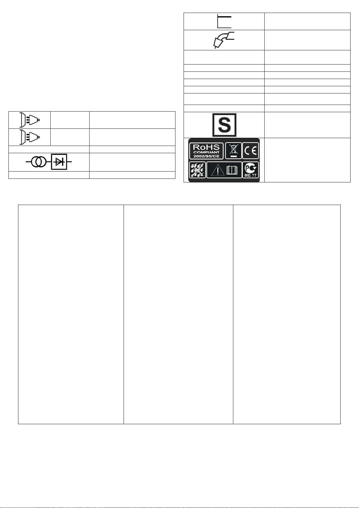
- Gennemboring af emnet
Kan skyldes for langsom bevægelse af brænderen, for høj strøm eller
ukorrekt trå dforsyning.
- Stærk sprøjtning og porøsit et.
Kan skyldes for stor afstand af gasførerens tud fra emnet, snavs på
emnet, utilstrækkelig gastilførsel eller lav strøm. Det er nødvendigt at
kontrollere de to parametre og huske at gastilførslen ikke må være under
7-8 liter/min., og at svejsningsstrømmen skal passe til den tråddiameter,
der anvendes. Det tilrådes at have en trykreguleringsventil i indgang og
udgang. På trykmåleren i udgang er det ligeledes muligt at aflæse
kap ac it e t e n i lit e r .
- Ustabil bue
Kan skyldes utilstrækkelig spænding, ujævn fremdrift af tråden,
utilstrækkelig beskyttelsesgas.
BETYDNING AF SKRIFT OG SYMBOLER
Beboels e k arakterist i k
MIG MAG l edn in g af fodre
U 1 … (V/Hz)
I 2 … (A) Elektrisk strøm til svejsning
I
(A) Liniens maksimale strømforbrug.
1 max
I
… (A) Effek tiv nuvære nde leveres
1 eff
X Arbejdscyklus
IP21
H Transform erens isolerin gs kl as se
Nominelle værdier i netspænding og
hyppighed
Svejsningerne enhedens beskyttelse
klasse
1 ~
3 ~
U 0 … (V) Nominel åbn e kredsloeb sp ænding
EN 60974-1
FEJL
Tråden fremføres ikke, når drivhjulet drejer
rundt
Trådforsyni ng i stød ell er me d afbry de ls e
Slukket bue jordklemme og emne
Porø st svejsesøm
Enfas et vekselspæn ding
Tr efaset v e k sel spæ nding
Transformator-ensretter
Relevant direktiv
Maskin en o ph ør er pludseligt med at
fungere efter langvarig brug
FEJLFINDING
ARSAGER
1) Snavs på trå df ørerens dyse
2) Afviklerens friction er for stor
3) Defect brӕnder
1) Defect kontaktdyse
2) Brӕ ndinger i kontaktdyse n
3) Snavs i drivhjulets fure
4) Slidt fure på drivhjul
1) Dårlig kontakt mellem
2) Kortslutning m ell em ko nta ktdy s en
og gasførerrøret
1) Manglende gasbeskyttelse på
grund af skorpedanneiser i
gasførerens dyse
2) Ukorre kt afstand ell er hӕldning af
brӕnderen
3) For lidt gas
4) Fugtige emner
5) Emner med m eget rust
1) Overophede t ma skine på gr un d af
overdriven brug, aktiveret
varmebeskyttelse
Svejsemaskine beregnet til
anvend else i omg ivels er, hvor der er
øget fare for elektrisk stød
Symboler henviser til
sikkerhedsbestemmelser
AFHJӔLPNING
Blӕs med luft
Slӕk friktionen
Control ler tr åd f ør er ens kappe
Udskift
Udskift
Rengør
Udskift
Stram klemmen, og controller
Rengør eller udskift kontaktdysen og
gasføreren
Fjern skorpedanneiserne, eller udskift
dysen
Afstand en me llem brӕnderen og emnet skal
vӕre 5 – 10 mm. Hӕldningen må ikke vӕ re
mindre end 6 0 i forh old til emnet
Øg mӕngden
Tør med en varmluftpistol eller andet
Rens emnerne for rust
Lad maskinen afkøle i mindst 20 – 30
minutter
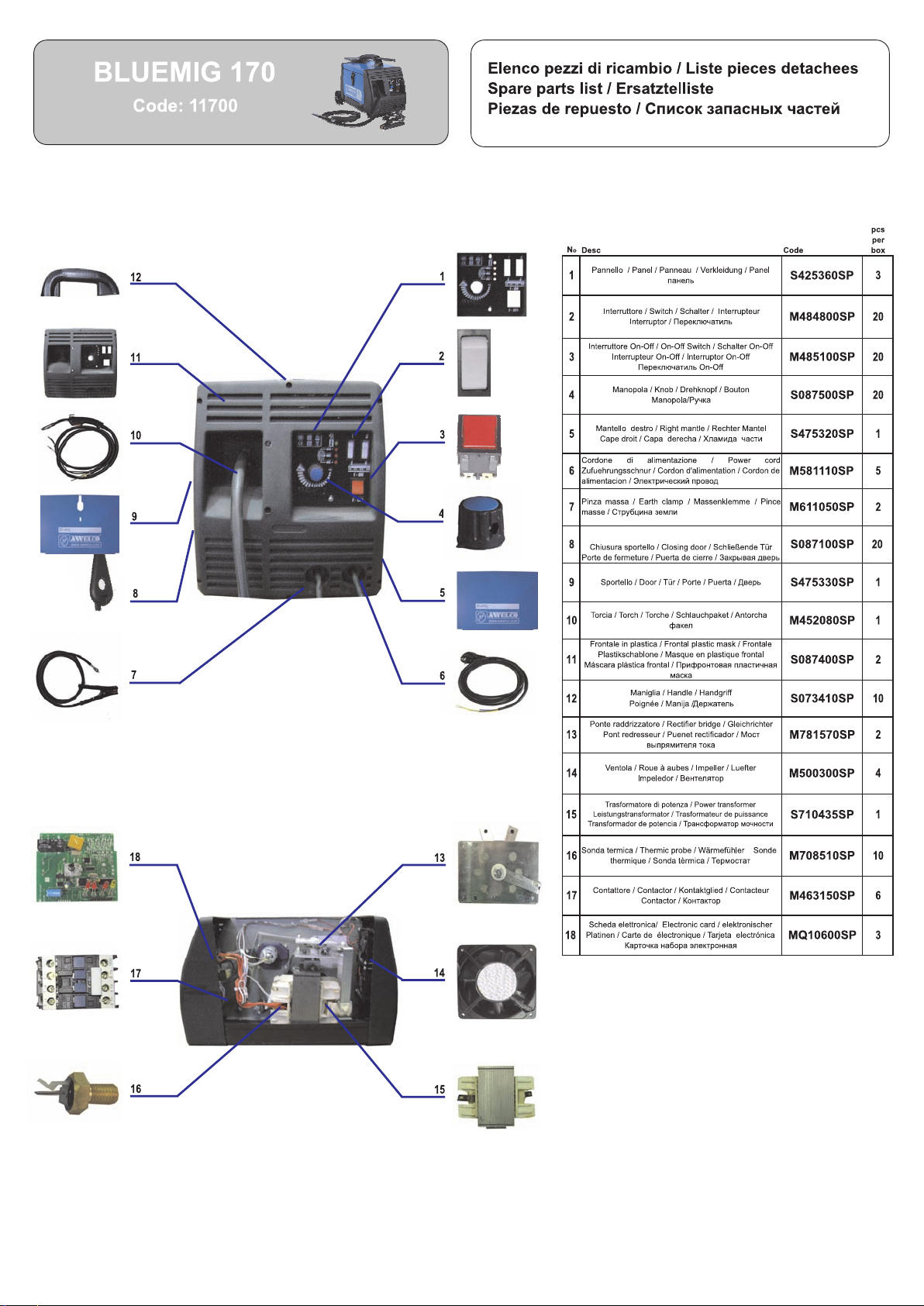
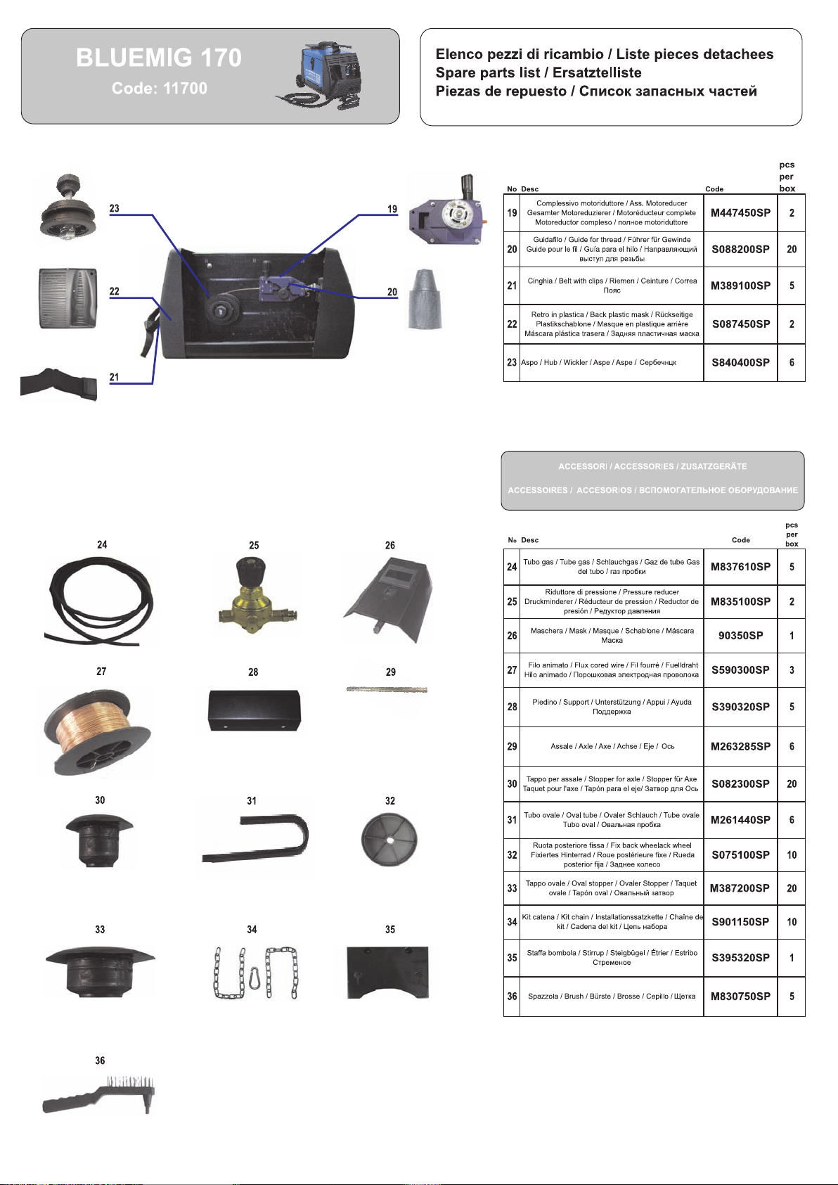
 Loading...