


U642B
Intervaland Wipe/ Wash Wiper Control IC
Description
As a convenience feature of the windshield wiper intermittent and wipe/wash operation are implemented in most of the automobiles. The U642B is the low-cost solution for an accurate timing function control. Wipe/wash mode has priority over interval mode. Interval pause and afterwiping time can be set to fixed values by
using resistors in a broad time range. Added value can be provided with an individual, continuous adjustment of the interval pause by a potentiometer which may be built into the stalk. For proper operation it is mandatory to feed the signal of the wiper motor`s park switch into U642B.
Features
Interval pause: 4 to 20 s |
|
One external capacitor, determines all time sequences |
Afterwiping time: 2 to 20 s |
Relay driver with Z-diode |
|
|
|
|
Wiper motor's park switch |
|
Interference protection according to VDE 0839 or |
|
ISO/TR 7637/1 |
|
|
|
|
Wipe/wash mode priority |
|
Load-dump protected |
Block Diagram
VS |
OUT |
|
|
PARK |
|
WASH |
|
8 |
7 |
|
|
6 |
|
|
5 |
|
|
|
|
|
VRef |
|
VRef |
|
Load-dump |
|
|
|
Park switch |
Input |
|
|
|
|
|
comparator |
comparator |
||
|
comparator |
|
|
|
|
|
|
|
VRef |
|
|
|
|
|
|
|
|
|
|
Logic |
|
Wipe / wash |
|
|
|
|
|
|
|
|
|
|
VRef |
|
|
|
|
|
comparator |
|
|
|
|
|
|
|
|
|
Interval |
A |
B |
C |
D |
E |
F |
|
comparator |
||||||
|
|
|
|
|
|
|
|
1 |
|
2 |
|
|
3 |
|
4 |
GND |
|
INT |
|
|
Ct |
|
94 8950 |
|
|
|
|
Rt |
|||
Figure 1. Block diagram
Rev. A4, 10-Apr-01 |
1 (7) |
U642B
Ordering Information
Extended Type Number |
Package |
Remarks |
U642B |
DIP8 |
|
U642B±FP |
SO8 |
|
|
|
|
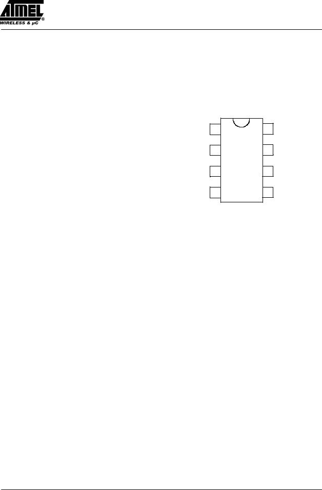
Pin Description
Pin |
Symbol |
Function |
GND |
1 |
8 |
VS |
|
1 |
GND |
Ground |
|||||
|
|
|
|
||||
2 |
INT |
Interval switch |
INT |
2 |
7 |
OUT |
|
3 |
Ct |
Timing capacitor C2 |
|||||
|
U642B |
|
|||||
4 |
Rt |
Afterwiping time resistance |
|
|
|||
Ct |
3 |
6 |
PARK |
||||
5 |
WASH |
Wipe/Wash switch |
|
|
|
|
|
6 |
PARK |
Park switch for wiper motor |
Rt |
4 |
5 |
WASH |
|
7 |
OUT |
Relay control output |
|
|
93 7691 |
|
|
|
|
|
|
|
|
||
8 |
VS |
Supply voltage KI. 15 |
|
|
|
|
|
|
|
|
|
Figure 2. |
Pinning |
|
|
Circuit Description
Interval Function, Pin 2
By closing the interval switch, S2, to supply voltage, VBatt, the relay is activated. The internal current source (Pin 3) which holds the capacitor C2 in charged state is switched-off. As soon as there is a positive potential at the park switch (S1), the current source F (see figure 1) charges the capacitor C2 very fast. After the wiper operation is finished, S1 is again at ground potential, the relay is in ºoffº position ± interval pause begins ± the capacitor C2 is discharged through the current source C, till the voltage at Pin 3 is below the threshold of 2 V. Interval pause can be adjusted between 4 s to 20 s with the help of potentiometer R3. Now the relay switches on and the next interval cycle begins. Opening of switch S2 causes the current source A to discharge C2 immediately and current sources C and F are switched-off.
Wipe/Wash (WIWA) Operation, Pin 5
By closing the WIWA-switch, S3, to supply voltage,
VBatt, the water pump starts spraying water on the windscreen, the current source A is switched-off which keeps
the capacitor C2 in discharged state. Now the capacitor is charged through the current sources D and F, and when after a time interval of approximately 100 ms, the voltage
at the capacitor is greater than 6.5 V, the relay is turned on as long as the switch ºWIWAº is closed.
The after-wipe-time begins after the switch is open whereas the sources D and F are switched off and the source E is activated. Source E discharges the capacitor till the voltage is less than 2.2 V. The relay is off and the wiper-motor is supplied via the park switch until the park position will be reached. The after-wipe-time is determined by the current source E which can be regulated with the external resistor RTime. Afterwards the source A discharges the capacitor. The relay switch off is independent of the park switch S1.
Interval and WIWA Functions
The interval function is interrupted immediately when the wipe/ wash mode is activated. The current source A discharges the capacitor to a value of 2 V, afterwards the normal wash function starts.
Interval wiping starts immediately when the after-wipe- time is over. The switching delays are slightly shorter, because the capacitor is already charged to a value of 2 V.
The wipe/ wash function is not interrupted when interval switch S2 is activated. Interval function begins after the WIWA function is over.
2 (7) |
Rev. A4, 10-Apr-01 |

|
|
|
|
|
|
U642B |
|
|
|
|
|
10 k |
R6 |
10 k |
|
|
|
|
|
|
R5 |
|
|
Relay |
|
8 |
7 |
6 |
|
5 |
|
|
|
|
|
|
|
|
|
|
47 F |
|
|
U642B |
|
|
|
|
10 V |
C1 |
|
|
|
|
|
|
|
|
|
|
|
|
|
|
|
1 |
2 |
3 |
|
4 |
|
|
|
|
2.7 k |
C2 |
22 F |
|
|
|
R1 |
|
R2 |
10 V |
|
||
|
|
|
|
|
R4 |
|
|
|
510 |
|
|
Rtime = 130 k |
|
||
|
|
|
|
R3 |
|
|
|
S1 |
|
S2 |
|
10 k |
|
|
|
|
|
|
|
|
|
|
|
Park |
|
|
|
|
|
WIWA |
|
switch |
|
|
|
|
|
|
|
|
M |
|
|
|
|
M |
|
|
|
|
|
|
|
S3 |
|
|
|
|
|
|
|
|
31 |
Wiper motor |
|
|
Interval switch |
|
|
15 |
|
|
|
|
Water pump |
94 8951 |
|||
Figure 3. Application circuit with interval and wipe/wash operation
Rev. A4, 10-Apr-01 |
3 (7) |
 Loading...