


 Loading...
Z97M-PLUS
Motherboard

E9678
Second Edition
August 2014
Copyright© 2014 ASUSTeK COMPUTER INC. All Rights Reserved.
No part of this manual, including the products and software described in it, may be reproduced, transmitted, transcribed, stored in a retrieval system, or translated into any language in any form or by any means, except documentation kept by the purchaser for backup purposes, without the express written permission of ASUSTeK COMPUTER INC. (“ASUS”).
Product warranty or service will not be extended if: (1) the product is repaired, modified or altered, unless such repair, modification of alteration is authorized in writing by ASUS; or (2) the serial number of the product is defaced or missing.
ASUS PROVIDES THIS MANUAL “AS IS” WITHOUT WARRANTY OF ANY KIND, EITHER EXPRESS OR IMPLIED, INCLUDING BUT NOT LIMITED TO THE IMPLIED WARRANTIES OR CONDITIONS OF MERCHANTABILITY OR FITNESS FOR A PARTICULAR PURPOSE. IN NO EVENT SHALL ASUS, ITS DIRECTORS, OFFICERS, EMPLOYEES OR AGENTS BE LIABLE FOR ANY INDIRECT, SPECIAL, INCIDENTAL, OR CONSEQUENTIAL DAMAGES (INCLUDING DAMAGES FOR LOSS OF PROFITS, LOSS OF BUSINESS, LOSS OF USE OR DATA, INTERRUPTION OF BUSINESS AND THE LIKE), EVEN IF ASUS HAS BEEN ADVISED OF THE POSSIBILITY OF SUCH DAMAGES ARISING FROM ANY DEFECT OR ERROR IN THIS MANUAL OR PRODUCT.
SPECIFICATIONS AND INFORMATION CONTAINED IN THIS MANUAL ARE FURNISHED FOR INFORMATIONAL USE ONLY, AND ARE SUBJECT TO CHANGE AT ANY TIME WITHOUT NOTICE, AND SHOULD NOT BE CONSTRUED AS A COMMITMENT BY ASUS. ASUS ASSUMES NO RESPONSIBILITY OR LIABILITY FOR ANY ERRORS OR INACCURACIES THAT MAY APPEAR IN THIS MANUAL, INCLUDING THE PRODUCTS AND SOFTWARE DESCRIBED IN IT.
Products and corporate names appearing in this manual may or may not be registered trademarks or copyrights of their respective companies, and are used only for identification or explanation and to the owners’ benefit, without intent to infringe.
Offer to Provide Source Code of Certain Software
This product contains copyrighted software that is licensed under the General Public License (“GPL”), under the Lesser General Public License Version (“LGPL”) and/or other Free Open Source Software Licenses. Such software in this product is distributed without any warranty to the extent permitted by the applicable law. Copies of these licenses are included in this product.
Where the applicable license entitles you to the source code of such software and/or other additional data, you may obtain it for a period of three years after our last shipment of the product, either
(1)for free by downloading it from http://support.asus.com/download
or
(2)for the cost of reproduction and shipment, which is dependent on the preferred carrier and the location where you want to have it shipped to, by sending a request to:
ASUSTeK Computer Inc.
Legal Compliance Dept.
15 Li Te Rd.,
Beitou, Taipei 112
Taiwan
In your request please provide the name, model number and version, as stated in the About Box of the product for which you wish to obtain the corresponding source code and your contact details so that we can coordinate the terms and cost of shipment with you.
The source code will be distributed WITHOUT ANY WARRANTY and licensed under the same license as the corresponding binary/object code.
This offer is valid to anyone in receipt of this information.
ASUSTeK is eager to duly provide complete source code as required under various Free Open Source Software licenses. If however you encounter any problems in obtaining the full corresponding source code we would be much obliged if you give us a notification to the email address gpl@asus.com, stating the product and describing the problem (please DO NOT send large attachments such as source code archives, etc. to this email address).
ii

Contents
Safety information...................................................................................................... |
vi |
About this guide......................................................................................................... |
vii |
Z97M-PLUS specifications summary........................................................................ |
ix |
Package contents..................................................................................................... |
xiii |
Installation tools and components.......................................................................... |
xiv |
Chapter 1: |
Product Introduction |
|
|
1.1 |
Special features.......................................................................................... |
1-1 |
|
|
1.1.1 |
Product highlights........................................................................ |
1-1 |
|
1.1.2 |
5X Protection............................................................................... |
1-2 |
|
1.1.3 |
ASUS Exclusive Features............................................................ |
1-2 |
|
1.1.4 |
Other special features.................................................................. |
1-3 |
1.2 |
Motherboard overview............................................................................... |
1-3 |
|
|
1.2.1 |
Before you proceed..................................................................... |
1-3 |
|
1.2.2 |
Motherboard layout...................................................................... |
1-4 |
|
1.2.3 |
Central Processing Unit (CPU).................................................... |
1-6 |
|
1.2.4 |
System memory........................................................................... |
1-7 |
|
1.2.5 |
Expansion slots............................................................................ |
1-9 |
|
1.2.6 |
Jumpers..................................................................................... |
1-11 |
|
1.2.7 |
Onboard buttons and switches.................................................. |
1-12 |
|
1.2.8 |
Onboard LEDs........................................................................... |
1-14 |
|
1.2.9 |
Internal connectors.................................................................... |
1-15 |
Chapter 2: |
Basic installation |
|
|
2.1 |
Building your PC system........................................................................... |
2-1 |
|
|
2.1.1 |
Motherboard installation.............................................................. |
2-1 |
|
2.1.2 |
CPU installation........................................................................... |
2-3 |
|
2.1.3 |
CPU heatsink and fan assembly installation................................ |
2-4 |
|
2.1.4 |
DIMM installation......................................................................... |
2-6 |
|
2.1.5 |
ATX Power connection................................................................ |
2-7 |
|
2.1.6 |
SATA device connection.............................................................. |
2-8 |
|
2.1.7 |
Front I/O Connector..................................................................... |
2-9 |
|
2.1.8 |
Expansion Card installation....................................................... |
2-10 |
2.2 |
Motherboard rear and audio connections.............................................. |
2-11 |
|
|
2.2.1 |
Rear I/O connection................................................................... |
2-11 |
|
2.2.2 |
Audio I/O connections................................................................ |
2-13 |
2.3 |
Starting up for the first time.................................................................... |
2-15 |
|
2.4 |
Turning off the computer......................................................................... |
2-15 |
|
iii

Chapter 3: |
BIOS setup |
|
|
3.1 |
Knowing BIOS............................................................................................. |
3-1 |
|
3.2 |
BIOS setup program................................................................................... |
3-2 |
|
|
3.2.1 |
EZ Mode...................................................................................... |
3-3 |
|
3.2.2 |
Advanced Mode........................................................................... |
3-4 |
|
3.2.3 |
QFan Control............................................................................... |
3-7 |
|
3.2.4 |
EZ Tuning Wizard........................................................................ |
3-9 |
3.3 |
My Favorites.............................................................................................. |
3-11 |
|
3.4 |
Main menu................................................................................................. |
3-13 |
|
3.5 |
Ai Tweaker menu...................................................................................... |
3-15 |
|
3.6 |
Advanced menu........................................................................................ |
3-29 |
|
|
3.6.1 |
CPU Configuration..................................................................... |
3-30 |
|
3.6.2 |
PCH Configuration..................................................................... |
3-33 |
|
3.6.3 |
PCH Storage Configuration....................................................... |
3-34 |
|
3.6.4 |
System Agent Configuration...................................................... |
3-36 |
|
3.6.5 |
USB Configuration..................................................................... |
3-37 |
|
3.6.6 |
Platform Misc Configuration....................................................... |
3-38 |
|
3.6.7 |
Onboard Devices Configuration................................................. |
3-40 |
|
3.6.8 |
APM Configuration..................................................................... |
3-42 |
|
3.6.9 |
Network Stack Configuration..................................................... |
3-43 |
3.7 |
Monitor menu............................................................................................ |
3-44 |
|
3.8 |
Boot menu................................................................................................. |
3-47 |
|
3.9 |
Tool menu.................................................................................................. |
3-53 |
|
|
3.9.1 |
ASUS EZ Flash 2 Utility............................................................. |
3-53 |
|
3.9.2 |
ASUS Overclocking Profile........................................................ |
3-54 |
|
3.9.3 |
ASUS SPD Information.............................................................. |
3-55 |
3.10 |
Exit menu................................................................................................... |
3-56 |
|
3.11 |
Updating BIOS.......................................................................................... |
3-57 |
|
|
3.11.1 |
EZ Update.................................................................................. |
3-57 |
|
3.11.2 |
ASUS EZ Flash 2....................................................................... |
3-58 |
|
3.11.3 |
ASUS CrashFree BIOS 3.......................................................... |
3-59 |
|
3.11.4 |
ASUS BIOS Updater.................................................................. |
3-60 |
Chapter 4: |
Software support |
|
|
4.1 |
Installing an operating system.................................................................. |
4-1 |
|
4.2 |
Support DVD information........................................................................... |
4-1 |
|
|
4.2.1 |
Running the support DVD............................................................ |
4-1 |
|
4.2.2 |
Obtaining the software manuals.................................................. |
4-2 |
iv

4.3 |
Software information.................................................................................. |
4-3 |
|
4.4 |
AI Suite 3 |
..................................................................................................... |
4-3 |
|
4.4.1 .................................................................................. |
DIGI+ VRM |
4-6 |
|
4.4.2 ............................................................................................. |
EPU |
4-7 |
|
4.4.3 ................................................................................ |
TurboV EVO |
4-8 |
|
4.4.4 .................................................................................. |
Fan Xpert 3 |
4-9 |
|
4.4.5 ........................................................................... |
USB 3.0 Boost |
4-11 |
|
4.4.6 .................................................................................. |
EZ Update |
4-12 |
|
4.4.7 ............................................................................... |
Push Notice |
4-13 |
|
4.4.8 .................................................................... |
System Information |
4-16 |
|
4.4.9 ....................................................................................... |
Version |
4-17 |
4.5 |
Audio configurations................................................................................ |
4-18 |
|
Chapter 5: |
RAID support |
|
|
5.1 |
RAID configurations................................................................................... |
5-1 |
|
|
5.1.1 |
RAID definitions........................................................................... |
5-1 |
|
5.1.2 |
Installing Serial ATA hard disks................................................... |
5-2 |
|
5.1.3 |
Setting the RAID item in BIOS..................................................... |
5-2 |
|
5.1.4 |
Intel® Rapid Storage Technology Option ROM utility................... |
5-3 |
5.2 |
Creating a RAID driver disk....................................................................... |
5-7 |
|
|
5.2.1 |
Creating a RAID driver disk without entering the OS................... |
5-7 |
|
5.2.2 |
Creating a RAID driver disk in Windows®.................................... |
5-8 |
|
5.2.3 |
Installing the RAID driver during Windows® OS installation......... |
5-8 |
Appendices |
|
|
|
Notices |
..................................................................................................................... |
|
A-1 |
ASUS contact information...................................................................................... |
A-3 |
||
v

Safety information
Electrical safety
•To prevent electrical shock hazard, disconnect the power cable from the electrical outlet before relocating the system.
•When adding or removing devices to or from the system, ensure that the power cables for the devices are unplugged before the signal cables are connected. If possible, disconnect all power cables from the existing system before you add a device.
•Before connecting or removing signal cables from the motherboard, ensure that all power cables are unplugged.
•Seek professional assistance before using an adapter or extension cord. These devices could interrupt the grounding circuit.
•Ensure that your power supply is set to the correct voltage in your area. If you are not sure about the voltage of the electrical outlet you are using, contact your local power company.
•If the power supply is broken, do not try to fix it by yourself. Contact a qualified service technician or your retailer.
Operation safety
•Before installing the motherboard and adding devices on it, carefully read all the manuals that came with the package.
•Before using the product, ensure all cables are correctly connected and the power cables are not damaged. If you detect any damage, contact your dealer immediately.
•To avoid short circuits, keep paper clips, screws, and staples away from connectors, slots, sockets and circuitry.
•Avoid dust, humidity, and temperature extremes. Do not place the product in any area where it may become wet.
•Place the product on a stable surface.
•If you encounter technical problems with the product, contact a qualified service technician or your retailer.
vi

About this guide
This user guide contains the information you need when installing and configuring the motherboard.
How this guide is organized
This guide contains the following parts:
•Chapter 1: Product introduction
This chapter describes the features of the motherboard and the new technology it supports. It includes description of the switches, jumpers, and connectors on the motherboard.
•Chapter 2: Basic installation
This chapter lists the hardware setup procedures that you have to perform when installing system components.
•Chapter 3: BIOS setup
This chapter tells how to change system settings through the BIOS Setup menus. Detailed descriptions of the BIOS parameters are also provided.
•Chapter 4: Software support
This chapter describes the contents of the support DVD that comes with the motherboard package and the software.
•Chapter 5: RAID support
This chapter describes the RAID configurations.
Where to find more information
Refer to the following sources for additional information and for product and software updates.
1.ASUS websites
The ASUS website provides updated information on ASUS hardware and software products. Refer to the ASUS contact information.
2.Optional documentation
Your product package may include optional documentation, such as warranty flyers, that may have been added by your dealer. These documents are not part of the standard package.
vii

Conventions used in this guide
To ensure that you perform certain tasks properly, take note of the following symbols used throughout this manual.
DANGER/WARNING: Information to prevent injury to yourself when trying to complete a task.
CAUTION: Information to prevent damage to the components when trying to complete a task
IMPORTANT: Instructions that you MUST follow to complete a task.
NOTE: Tips and additional information to help you complete a task.
Typography
Bold text |
Indicates a menu or an item to select. |
Italics |
Used to emphasize a word or a phrase. |
<Key> |
Keys enclosed in the less-than and greater-than sign |
|
means that you must press the enclosed key. |
|
Example: <Enter> means that you must press the Enter or |
|
Return key. |
<Key1> + <Key2> + <Key3> |
If you must press two or more keys simultaneously, the key |
|
names are linked with a plus sign (+). |
viii

Z97M-PLUS specifications summary
CPU |
LGA1150 socket for the 4th, New 4th & 5th Generation Intel® Core™ i7/ |
|
Core™ i5 / Core™ i3, Pentium®, and Celeron® processors |
|
Supports 22nm CPU |
|
Supports Intel® Turbo Boost Technology 2.0* |
|
* The Intel® Turbo Boost Technology 2.0 support depends on the CPU types. |
|
** Refer to www.asus.com for Intel® CPU support list. |
Chipset |
Intel® Z97 Express Chipset |
Memory |
4 x DIMM, max. 32GB, DDR3 3200(O.C.)*/3100(O.C.)*/3000(O.C.)*/ |
|
2933(O.C.)*/2800(O.C.)*/2666(O.C.)*/2600(O.C.)*/2400(O.C.)*/ |
|
2250(O.C.)*/2200(O.C.)*/2133(O.C.)*/2000(O.C.)*/ 1866(O.C.)*/ |
|
1600/1333MHz, non-ECC, un-buffered memory |
|
Dual-channel memory architecture |
|
Supports Intel® Extreme Memory Profile (XMP) |
|
* Hyper DIMM support is subject to the physical characteristics of individual |
|
CPUs. Please refer to Memory QVL (Qualified Vendors List) for details. |
|
** Refer to www.asus.com for the Memory QVL (Qualified Vendors List). |
|
|
Expansion slots |
1 x PCI Express 3.0/2.0 x16 slot (at x16 mode) |
|
1 x PCI Express 2.0 x16 slot (max. at x4 mode, compatible with PCIe x1 |
|
and x4 devices) |
|
2 x PCI slots |
|
|
Graphics |
Integrated Graphics Processor - Intel® HD Graphics support |
|
Multi-VGA output support: HDMI/DVI-D/RGB port |
|
Supports HDMI with max. resolution of 4096 x 2160 @24Hz / 2560 x |
|
1600 @60Hz |
|
Supports DVI-D with max. resolution of 1920 x 1200 @60Hz |
|
Supports RGB with max. resolution of 1920 x 1200 @60Hz |
|
Supports Intel® InTru™ 3D, Intel® Quick Sync Video, Intel® Clear Video |
|
HD Technology, and Intel® Insider™ |
|
Supports up to three displays simultaneously |
|
Maximum shared memory of 512MB |
|
|
Multi-GPU support |
Supports AMD® Quad-GPU CrossFireX™ Technology |
Storage |
Intel® Z97 Express Chipset with RAID 0, 1, 5, 10 and Intel® |
|
Rapid Storage Technology 13 support |
|
- 1 x M.2 Socket 3* |
|
- 6 x SATA 6.0 Gb/s ports (gray) |
|
- Supports Intel® Smart Response Technology, Intel® Rapid Start |
|
Technology, and Intel® Smart Connect Technology** |
|
* This socket supports M Key and type 2242/2260/2280 storage devices (Type |
|
2242 storage device is supported on Rev. 2.00 or later versions of this |
|
motherboard). |
|
** These functions will work depending on the CPU installed. |
|
|
LAN |
Gigabit Intel LAN controllers802.3az Energy Efficient Ethernet (EEE) |
|
appliance |
|
Intel® I218-V Gigabit LANDual interconnect between the integrated |
|
LAN controller and physical layer (PHY) |
|
(continued on the next page) |
ix

Z97M-PLUS specifications summary
Audio |
Realtek® ALC887 7.1-channel high definition audio CODEC featuring |
|
|
Crystal Sound 2 |
|
|
- |
Audio Shielding: Ensures precision analog/digital separation and greatly |
|
|
reduced multi-lateral interference |
|
- |
Dedicated audio PCB layers: Separate layers for left and right channels to |
|
|
guard the quality of the sensitive audio signals |
|
- |
Audio amplifier: Provides the highest-quality sound for headphone and |
|
|
speakers |
|
- Premium Japanese-made audio capacitors: Provide warm, natural and |
|
|
|
immersive sound with exceptional clarity and fidelity |
|
- |
Unique de-pop circuit: Reduces start-up popping noise to audio outputs |
|
- |
Supports jack-detection, multi-streaming, and front panel jack-retasking |
USB |
Intel® Z97 Express Chipset - supports ASUS USB 3.0 |
|
|
Boost |
|
|
- |
6 x USB 3.0/2.0 ports (2 ports at mid-board, 4 ports at rear panel |
|
|
[blue]) |
|
- |
8 x USB 2.0/1.1 ports (6 ports at mid-board, 2 ports at rear panel) |
ASUS special features |
High Performance |
|
|
ASUS 5X PROTECTION |
|
|
- |
ASUS motherboards safeguard your PC with 5X PROTECTION: |
|
|
DIGI+ VRM, DRAM Fuse, ESD Guards, High-Quality 5K-Hour |
|
|
Solid Capacitors, and Stainless Steel Back I/O ensure the best |
|
|
quality, reliability, and durability |
|
|
ASUS Digital Power Design |
|
|
- ASUS Digital Power Control: Digital Power Design for the CPU |
|
|
- ASUS 4 Phase Power Design |
|
|
- ASUS CPU power utility |
|
|
ASUS DRAM Fuse |
|
|
- Enhanced DRAM overcurrent protection and short circuit |
|
|
damage prevention |
|
|
ASUS ESD Guards |
|
|
- Enhanced ESD protection |
|
|
ASUS High-Quality 5K Solid Capacitors |
|
|
- 2.5x Longer lifespan with excellent durability |
|
|
ASUS Stainless Steel Back I/O |
|
|
- 3x More durable corrosion-resistant coating |
|
UEFI BIOS |
|
|
- |
Most advanced options with fast response time |
M.2 onboard
-The latest transfer technologies with up to 10 Gb/s data transfer speeds
ASUS Fan Xpert3
-Featuring Fan Auto Tuning function and multiple thermistors selection for optimized system cooling control.
ASUS EPU
- EPU
Interactive HomeCloud
Media Streamer
-Pipe music or movies from your PC to a smart TV
-Media Streamer app for portable smartphone/tablet, supporting iOS 7 and Android 4.0 system
(continued on the next page)
x
Z97M-PLUS specifications summary
ASUS special |
Gaming Scenario |
features |
Crystal Sound 2 |
|
|
|
- Flawless audio that makes you part of the game |
|
Steam support |
|
- Compatible with the most fun gaming platform under Windows® system |
ASUS Exclusive Features
- USB 3.0 Boost
- Ai Charger
- AI Suite 3
- Disk Unlocker
- MemOK!
EZ DIY
Push Notice
- Monitor your PC status with smart devices in real time
UEFI BIOS EZ Mode
- featuring friendly graphics user interface
- ASUS O.C. Tuner
- ASUS CrashFree BIOS 3
- ASUS EZ Flash 2
Q-Design
- ASUS Q-DIMM
- ASUS Q-Slot
ASUS quiet thermal |
Quiet Thermal Design |
|
solution |
- |
ASUS Fan Xpert 3 |
|
||
|
- |
Stylish Fanless Design: PCH Heat-sink & MOS Heat-sink solution |
ASUS exclusive overclocking features
Precision Tweaker 2
-vCore: Adjustable CPU Core voltage at 0.001V increment
-iGPU: Adjustable CPU Graphics voltage at 0.001V increment
-vCCIO: Adjustable Analog and Digital I/O voltage at 0.001V increment
-vCCIN: Adjustable CPU Input voltage at 0.01V increment
-vCCSA: Adjustable CPU System Agent voltage at 0.001V increment
-vDRAM Bus: 124-step Memory voltage control
-vPCH: 154-step Chipset voltage control
SFS (Stepless Frequency Selection)
-BCLK/PCIE frequency tuning from 80MHz up to 300MHz at 0.1MHz increment
Overclocking Protection
- ASUS C.P.R.(CPU Parameter Recall)
(continued on the next page)
xi

Z97M-PLUS specifications summary
Back Panel I/O Ports |
1 x PS/2 mouse / keyboard combo port |
|
|
1 x HDMI port |
|
|
1 x DVI-D port |
|
|
1 x RGB port |
|
|
1 x LAN (RJ-45) port |
|
|
4 x USB 3.0/2.0 ports (blue) |
|
|
2 x USB 2.0/1.1 ports |
|
|
6 x audio jacks support 7.1-channel |
|
Internal I/O |
1 x 19-pin USB 3.0/2.0 connector supports additional 2 USB ports |
|
connectors / |
3 x USB 2.0/1.1 connectors support additional 6 USB ports |
|
jumpers / buttons |
||
1 x M.2 Socket 3 (for M Key, type 2242/2260/2280 devices)* |
||
|
||
|
6 x SATA 6.0 Gb/s connectors (gray) |
|
|
1 x 4-pin CPU Fan connector for both 3-pin (DC mode) and 4-pin (PWM |
|
|
mode) CPU coolers control** |
|
|
2 x 4-pin Chassis Fan connectors for both 3-pin (DC mode) and 4-pin (PWM |
|
|
mode) coolers control |
|
|
1 x Front panel audio connector (AAFP) |
|
|
1 x S/PDIF out header |
|
|
1 x 24-pin EATX Power connector |
|
|
1 x 8-pin EATX 12V Power connector |
|
|
1 x System panel connector |
|
|
1 x MemOK! button |
|
|
1 x GPU Boost switch (advanced two-stage adjustments) |
|
|
1 x Parallel port connector |
|
|
1 x Clear CMOS jumper |
|
|
1 x TPM header |
|
|
1 x COM port |
|
|
* This socket supports M Key and type 2242/2260/2280 storage devices (Type 2242 |
|
|
storage device is supported on Rev. 2.00 or later versions of this motherboard). |
|
|
** The CPU Q-Fan control setting is set as default in Auto mode for detecting the |
|
|
type of CPU fan installed and switches to the control mode automatically. |
|
|
|
|
BIOS features |
64 Mb Flash ROM, UEFI AMI BIOS, PnP, DMI 2.7, WfM 2.0, SM BIOS 2.8, |
|
|
ACPI 5.0, Multi-language BIOS, ASUS EZ Flash 2, CrashFree BIOS 3, F11 |
|
|
EZ Tuning Wizard, F6 Qfan Control, F3 My Favorites, Quick Note, Last |
|
|
Modified Log, F12 PrintScreen function, F3 Shortcut function, and ASUS |
|
|
DRAM SPD (Serial Presence Detect) memory information |
|
Manageability |
WfM 2.0, DMI 2.7, WOL by PME, PXE |
|
Support DVD |
Drivers |
|
contents |
ASUS Utilities |
|
|
||
|
EZ Update |
|
|
Anti-virus software (OEM version) unique features |
|
|
|
|
Operating system |
Windows® 8.1 |
|
support |
Windows® 8 |
|
|
Windows® 7 |
|
Form factor |
uATX form factor: 9.6 in. x 8.8 in. (24.4 cm x 22.4 cm) |
Specifications are subject to change without notice.
xii
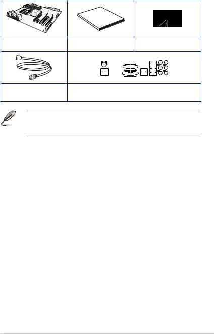
Package contents
Check your motherboard package for the following items
Guide
User
ASUS Z97M-PLUS motherboard |
User guide |
|
Support DVD |
|||
|
|
|
|
|
|
|
|
|
|
|
|
|
|
|
|
|
|
|
|
|
|
|
|
|
|
|
|
|
|
|
|
|
|
|
|
|
|
|
|
|
|
|
|
|
|
|
|
|
|
|
|
|
|
|
|
2 x Serial ATA 6.0 Gb/s cables |
1 x ASUS I/O-Shield |
•If any of the above items is damaged or missing, contact your retailer.
•The illustrations above are for reference only. Actual product specifications may vary with different models.
xiii
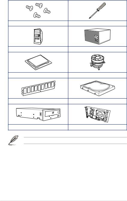
Installation tools and components
1 bag of screws |
Philips (cross) screwdriver |
PC chassis |
Power supply unit |
Intel® LGA1150 CPU |
Intel® LGA1150 compatible CPU Fan |
DIMM |
SATA hard disk drive |
SATA optical disc drive (optional) |
Graphics card (optional) |
The tools and components in the table above are not included in the motherboard package.
xiv

Product introduction |
1 |
1.1Special features
1.1.1Product highlights
Intel® LGA1150 4th, New 4th & 5th Generation Core™ i7 / Core™ i5 / Core™ i3, Pentium®, and Celeron® Processors Ready
This motherboard supports the 4th, New 4th & 5th Generation Intel® Core™ i7 / Core™ i5 / Core™ i3, Pentium®, and Celeron® processors in the LGA1150 package. It provides great graphics and system performance with its GPU, dual-channel DDR3 memory slots and PCI Express 2.0/3.0 expansion slots.
Intel® Z97 Express Chipset
Intel® Z97 Express Chipset is a single chipset that supports the LGA1150 socket for the 4th, New 4th & 5th Generation Intel® Core™ i7/ Core™ i5/ Core™ i3, Pentium®, and Celeron® processors. It utilizes the serial point-to-point links, which increases bandwidth and enhances the system’s performance. It natively supports up to six USB 3.0 ports, six SATA 6 Gb/s ports, and M.2 support for faster data retrieval. It also enables the iGPU function for Intel® integrated graphics performance.
PCI Express® 3.0
PCI Express® 3.0 (PCIe 3.0) is the PCI Express bus standard that provides twice the performance and speed of PCIe 2.0. It provides an optimal graphics performance, unprecedented data speed, and seamless transition with its complete backward compatibility to PCIe 1.0/2.0 devices.
Intel® Desktop Responsiveness Technologies
Intel Desktop Responsiveness Technologies comprise of three technologies: Intel Rapid Start Technology, Intel Smart Response Technology, and Intel Smart Response Technology. These technologies provide faster and better performance for your computer, allow your system to receive the freshest updates from the Internet, and quickly resume your system from a deep sleep or hibernate mode.
Dual-Channel DDR3 3200 (O.C) / 1600 / 1333 MHz Support
The motherboard supports the dual-channel DDR3 memory that features data transfer rates of DDR3 3200 (O.C.)* / 1600 / 1333 MHz to boost the system’s performance, and to meet the higher bandwidth requirements of 3D graphics, multimedia and Internet applications.
Quad-GPU CrossFireX™ Support
This motherboard features the most powerful Intel® Z97 platform that optimizes PCIe allocation in multi-GPU CrossFireX™ solution, giving you a brand-new gaming enjoyment.
Chapter 1
ASUS Z97M-PLUS |
1-1 |

1 Chapter
M.2 Support
This motherboard features the M.2 slot, which shares bandwidth with PCI Express x2 slot to speed up data transfer up to 10 Gb/s. This helps enhance the performance of your SSD (Solid State Drive) that is dedicated only to the operating system. The M.2 slot also includes Intel Rapid Storage Technology support for faster access to data and applications, and quicker wake up time for your system.
Complete USB 3.0 integration
This motherboard offers you the strategic USB 3.0 accessibility for both the front and rear panels, allowing you to experience the convenience of the latest plug and play connectivity solution at speed up to ten times faster than USB 2.0.
Native SATA 6 Gb/s support
With Intel® Z97 Express Chipset natively support for the next-generation Serial ATA (SATA) storage interface, this motherboard delivers up to 6.0 Gb/s data transfer rates. It also provides enhanced scalability, faster data retrieval, double the bandwidth of current bus systems.
Gigabit LAN support
Z97M-PLUS features Gigabit LAN design which complies with 802.3az Energy Efficient Ethernet (EEE) standard and allows a PC to serve as a network gateway for managing traffic between two separate networks. Intel® Gigabit LAN controller on this motherboard which reduces power consumption during normal operation and enhances faster transfer speed through dual interconnection between the Integrated LAN controller and Physical Layer (PHY).
1.1.25X Protection
5X PROTECTION
ASUS motherboards guard your PC with 5X PROTECTION. We use quality components like ESD units tested to strict standards that eliminate electrostatic interference, polyswitches (resettable fuses) around DRAM slots to prevent overcurrent and short-circuit damage, and a corrosion-resistant back I/O shield. All examples of ASUS providing the best possible reliability and durability.
1.1.3ASUS Exclusive Features
Crystal Sound 2
Crystal Sound 2 makes short work of optimizing audio settings for the way you want to listen, be it gaming, chatting, watching movies or relaxing to your favorite music. Onboard physical shielding, professional engineered design and premium components, including Japanesemade audio capacitors and operational amplifiers (op-amps), result in sound output that has exceptional clarity and fidelity. Discover a whole new dimension of superior audio and get ready to rule!
1-2 |
Chapter 1: Product introduction |

ASUS HomeCloud
ASUS HomeCloud creates a world without boundaries. It lets you access your PC remotely, stream multimedia content to wherever you want, and manage all your stuff from anywhereno matter where it’s stored. Use the built-in Wake on WAN feature to remotely wake and control your PC with a single smart device, anywhere and anytime. It even turns your hard drive into a private cloud, removing worries about storage limits. With HomeCloud, your PC becomes the gateway to your world.
1.1.4Other special features
ErP Ready
The motherboard is European Union’s Energy-related Products (ErP) ready, and ErP requires products to meet certain energy efficiency requirement in regards to energy consumptions. This is in line with ASUS vision of creating environment-friendly and energyefficient products through product design and innovation to reduce carbon footprint of the product and thus mitigate environmental impacts.
1.2Motherboard overview
1.2.1Before you proceed
Take note of the following precautions before you install motherboard components or change any motherboard settings.
• Unplug the power cord from the wall socket before touching any component.
•Before handling components, use a grounded wrist strap or touch a safely grounded object or a metal object, such as the power supply case, to avoid damaging them due to static electricity.
•Hold components by the edges to avoid touching the ICs on them.
•Whenever you uninstall any component, place it on a grounded antistatic pad or in the bag that came with the component.
•Before you install or remove any component, ensure that the ATX power supply is switched off or the power cord is detached from the power supply. Failure to do so may cause severe damage to the motherboard, peripherals, or components.
Chapter 1
ASUS Z97M-PLUS |
1-3 |

1.2.2Motherboard layout
1 |
|
2 |
3 |
4 |
|
5 |
1 |
6 |
|
|
|
|
||||||||||||||||||||||||
|
|
|
|
|
|
|
|
|
|
|
|
|
|
|
|
|
|
|
|
|
|
|
22.4cm(8.8in) |
|
|
|
||||||||||
|
|
|
|
|
|
|
|
|
|
GPU Boost |
|
|
|
|
|
|
|
|
|
|
|
|
CHA_FAN2 |
|||||||||||||
KBMS_USB78 |
|
|
|
|
|
|
|
|
|
|
|
|
|
|
|
|
|
|
|
|||||||||||||||||
|
|
|
|
|
|
|
|
|
|
|
|
|
|
|
|
|
|
|
||||||||||||||||||
|
|
|
|
|
|
|
|
|
|
|
|
|
|
|
|
|
|
|
||||||||||||||||||
|
|
|
|
|
|
|
|
|
|
|
|
|
|
|
|
|
|
|
|
|
|
|
|
|
|
|
|
|
|
|
||||||
|
|
|
|
|
|
|
|
|
|
|
|
CPU_FAN |
|
|
|
|
|
|
|
|
|
|
|
|
|
|
|
|||||||||
|
|
|
|
|
|
|
|
|
|
|
|
|
GPU_LED |
|
|
|
|
|
|
|
|
|
|
|
|
|
|
BATTERY |
||||||||
|
|
|
|
|
|
|
|
|
|
|
DIGI |
|
|
|
|
|
|
|
|
|
|
|
|
|
|
|
|
|
|
|
|
|
|
|
|
|
|
|
|
|
|
|
|
|
|
|
|
|
|
|
|
|
|
|
|
|
|
|
|
|
|
|
|
|
|
|
|||||||
|
|
|
|
|
|
|
|
|
|
|
+VRM |
|
|
|
|
|
|
|
|
|
|
|
|
|
|
|
|
|
|
|
|
|
|
|
|
|
DVI |
VGA |
HDMI
ASM 1442K
USB3_56
LAN_USB3_34
AUDIO
Intel
I218-V
Super
I/O
ALC 887
AAFP
EATX12V |
|
|
|
|
|
|
|
7 |
|
|
|
|
|
|
|
|
|
|
|
|
|
|
|
|
|
8 |
|
|
|
|
|
|
MemOK! |
9 |
|
|
|
module)pin-240 |
module)pin-240 |
module)pin-240 |
module)pin-240 |
DRAM_LED |
||
|
|
|
||||||
|
LGA1150 |
DIMMDDR3A1 (64bit, |
DIMMDDR3A2 (64bit, |
DIMMDDR3B1 (64bit, |
DIMMDDR3B2 (64bit, |
EATXPWR 1SATA6G |
|
24.4cm(9.6in) |
|
|
|
|
|
|
|
2 |
|
|
|
M.2(SOCKET3) |
|
|
USB312 |
2 |
34SATA6G |
|
CHA_FAN1 |
Z97M-PLUS |
|
|
SATA6G |
10 |
|||
|
|
|
|
|
|
|||
|
|
|
|
|
|
|
|
|
|
PCIEX16_1 |
|
|
|
|
|
SATA6G 56 |
|
|
|
|
|
|
|
|
11 |
|
|
PCI1 |
|
|
|
|
|
|
|
|
|
|
|
ASM |
|
Intel® |
|
|
|
|
|
|
|
Z97 |
|
|
|
|
PCI2 |
|
|
1083 |
|
|
|
|
|
|
|
|
|
|
|
|
|
|
|
|
SB_PWR |
|
|
|
12 |
|
|
PCIEX16_2 |
|
|
|
|
BIOS |
13 |
|
LPT |
SPDIF_OUT |
TPM |
COM |
USB910 |
USB1112 |
USB1314 |
PANEL |
|
|
|
|||||||
CLRTC |
20 |
19 |
18 |
17 |
16 |
15 |
14 |
Refer to 1.2.9 Internal connectors and 2.2.1 Rear I/O connection for more information about rear panel connectors and internal connectors.
1 Chapter
1-4 |
Chapter 1: Product introduction |

Layout contents
Connectors/Jumpers/Slots |
Page |
|
1. |
CPU and chassis fan connectors (4-pin CPU_FAN, 4-pin CHA_FAN1/2) |
1-18 |
2. |
ATX power connectors (24-pin EATXPWR, 8-pin EATX12V) |
1-20 |
3. |
GPU Boost LED (GPU_LED) |
1-14 |
4. |
GPU Boost switch |
1-13 |
5. |
LGA1150 CPU socket |
1-6 |
6. |
DDR3 DIMM slots |
1-7 |
7. |
USB 3.0 connector (20-1 pin USB3_12) |
1-16 |
8. |
DRAM LED (DRAM_LED) |
1-14 |
9. |
MemOK! button |
1-12 |
10. |
Intel® Z97 Serial ATA 6.0 Gb/s connectors (7-pin SATA6G_1-6) |
1-15 |
11. |
M.2 Socket 3 |
1-22 |
12. |
Standby power LED (SB_PWR) |
1-14 |
13. |
Clear RTC RAM (3-pin CLRTC) |
1-11 |
14. |
System panel connector (20-8 pin PANEL) |
1-21 |
15. |
USB 2.0 connectors (10-1 pin USB910, USB1112, USB1314) |
1-17 |
16. |
Serial port connector (10-1 pin COM) |
1-16 |
17. |
TPM header (20-1 pin TPM) |
1-19 |
18. |
Digital audio connector (4-1 pin SPDIF_OUT) |
1-17 |
19. |
LPT connector (26-1 pin LPT) |
1-20 |
20. |
Front panel audio connector (10-1 pin AAFP) |
1-19 |
|
|
|
Chapter 1
ASUS Z97M-PLUS |
1-5 |

1.2.3Central Processing Unit (CPU)
The motherboard comes with a surface mount LGA1150 socket designed for the 4th, New 4th & 5th Generation Intel® Core™ i7 / Core™ i5 / Core™ i3, Pentium™, and Celeron™ processors.
Z97M-PLUS
Z97M-PLUS CPU socket LGA1150
• Ensure that all power cables are unplugged before installing the CPU.
•Ensure that you install the correct CPU designed for LGA1150 only. DO NOT install a
CPU designed for LGA1155 and LGA1156 sockets on the LGA1150 socket.
•Upon purchase of the motherboard, ensure that the PnP cap is on the socket and the socket contacts are not bent. Contact your retailer immediately if the PnP cap is missing, or if you see any damage to the PnP cap/socket contacts/motherboard components. ASUS will shoulder the cost of repair only if the damage is shipment/ transit-related.
•Keep the cap after installing the motherboard. ASUS will process Return Merchandise
Authorization (RMA) requests only if the motherboard comes with the cap on the LGA1150 socket.
•The product warranty does not cover damage to the socket contacts resulting from incorrect CPU installation/removal, or misplacement/loss/incorrect removal of the PnP cap.
1 Chapter
1-6 |
Chapter 1: Product introduction |
1.2.4System memory
The motherboard comes with four Double Data Rate 3 (DDR3) Dual Inline Memory Modules (DIMM) slots.
A DDR3 module is notched differently from a DDR or DDR2 module. DO NOT install a DDR or DDR2 memory module to the DDR3 slot.
DIMM A1 |
DIMM A2 |
DIMM B1 |
DIMM B2 |
Z97M-PLUS |
|
|
|
Z97M-PLUS 240-pin DDR3 DIMM sockets
Recommended memory configurations
Chapter 1
ASUS Z97M-PLUS |
1-7 |
1 Chapter
Memory configurations
You may install 2GB, 4GB, and 8GB unbuffered and non ECC DDR3 DIMMs into the DIMM sockets.
• You may install varying memory sizes in Channel A and Channel B. The system maps the total size of the lower-sized channel for the dual-channel configuration. Any excess memory from the higher-sized channel is then mapped for single-channel operation.
•According to Intel CPU spec, DIMM voltage below 1.65V is recommended to protect the CPU.
•Always install DIMMs with the same CAS latency. For optimum compatibility, we recommend that you obtain memory modules from the same vendor.
•Due to the memory address limitation on 32-bit Windows® OS, when you install 4GB or more memory on the motherboard, the actual usable memory for the OS can be about 3GB or less. For effective use of memory, we recommend that you do any of the following:
a)Use a maximum of 3GB system memory if you are using a 32-bit Windows® OS.
b)Install a 64-bit Windows® OS when you want to install 4GB or more on the motherboard.
c)For more details, refer to the Microsoft® support site at http://support.microsoft. com/kb/929605/en-us.
•This motherboard does not support DIMMs made up of 512Mb (64MB) chips or less
(Memory chip capacity counts in Megabit, 8 Megabit/Mb = 1 Megabyte/MB).
• The default memory operation frequency is dependent on its Serial Presence Detect
(SPD), which is the standard way of accessing information from a memory module. Under the default state, some memory modules for overclocking may operate at a lower frequency than the vendor-marked value. To operate at the vendor-marked or at a higher frequency, refer to section 3.5 Ai Tweaker menu for manual memory frequency adjustment.
•For system stability, use a more efficient memory cooling system to support a full memory load (4 DIMMs) or overclocking condition.
•Memory modules with memory frequency higher than 2133MHz and their corresponding timing or the loaded XMP profile is not the JEDEC memory standard.
The stability and compatibility of the memory modules depend on the CPU’s capabilities and other installed devices.
•Always install the DIMMS with the same CAS Latency. For an optimum compatibility, we recommend that you install memory modules of the same version or data code (D/ C) from the same vendor. Check with the vendor to get the correct memory modules.
• ASUS exclusively provides hyper DIMM support function.
•Hyper DIMM support is subject to the physical characteristics of individual CPUs. Load the X.M.P. or D.O.C.P. settings in the BIOS for the hyper DIMM support.
•Visit the ASUS website for the latest QVL.
1-8 |
Chapter 1: Product introduction |
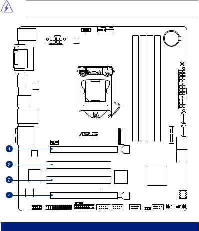
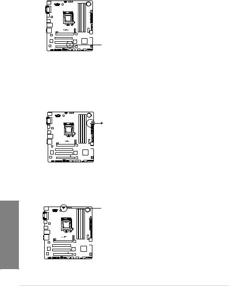
1.2.5Expansion slots
Unplug the power cord before adding or removing expansion cards. Failure to do so may cause you physical injury and damage motherboard components.
Z97M-PLUS
PCIEX16_1
PCI1
PCI2
PCIEX16_2
Slot No. |
|
Slot Description |
|
|
1 |
|
PCIe 3.0/2.0 x16_1 slot (at x16 mode) |
|
|
|
|
|
||
2 |
|
PCI slot 1 |
|
|
|
||||
3 |
|
PCI slot 2 |
|
1 |
4 |
|
PCIe 2.0 x16_2 slot (max. at x4 mode, compatible with PCIe x1 and x4 devices) |
|
|
|
|
Chapter |
||
|
|
|
|
|
|
|
|
|
|
|
|
|
|
|
ASUS Z97M-PLUS |
1-9 |
|
|
PCIe Express operating mode |
||
VGA configuration |
|
PCIe 3.0/2.0 x16_1 |
|
PCIe 2.0 x16_2 |
|
|
|
||
Single VGA/PCIe card |
|
x16 (single VGA recommended) |
|
N/A |
|
|
|||
|
|
|
|
|
Dual VGA/PCIe card |
|
x16 |
|
x4 |
•In single VGA card mode, use the PCIe 3.0/2.0 x16_1 slot (gray) for a PCI Express
x16 graphics card to get better performance.
•We recommend that you provide sufficient power when running CrossFireX™ mode.
•Connect a chassis fan to the motherboard connector labeled CHA_FAN1/2 when using multiple graphics cards for better thermal environment.
IRQ assignments for this motherboard
|
|
A |
B |
C |
D |
E |
F |
G |
H |
PCIe x16_1 |
|
shared |
– |
– |
– |
– |
– |
– |
– |
|
|||||||||
PCIe x16_2 |
|
shared |
– |
– |
– |
– |
– |
– |
– |
PCI1 |
|
– |
– |
– |
shared |
– |
– |
– |
– |
PCI2 |
|
shared |
– |
– |
– |
– |
– |
– |
– |
Intel SATA Controller |
|
– |
– |
– |
shared |
– |
– |
– |
– |
Intel LAN |
|
– |
– |
– |
– |
shared |
– |
– |
– |
Intel xHCI |
|
– |
– |
– |
– |
– |
shared |
– |
– |
Intel EHCI 1 |
|
– |
– |
– |
– |
– |
– |
– |
shared |
Intel EHCI 2 |
|
shared |
– |
– |
– |
– |
– |
– |
– |
|
|
|
|
|
|
|
|
|
|
HD Audio |
|
– |
– |
– |
– |
– |
– |
shared |
– |
1 Chapter
1-10 |
Chapter 1: Product introduction |

1.2.6Jumpers
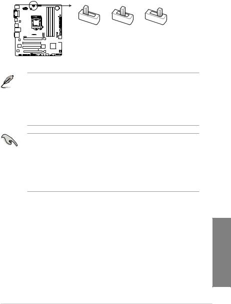
Clear RTC RAM (3-pin CLRTC)
This jumper allows you to clear the Real Time Clock (RTC) RAM in CMOS. You can clear the CMOS memory of date, time, and system setup parameters by erasing the CMOS RTC RAM data. The onboard button cell battery powers the RAM data in CMOS, which include system setup information such as system passwords.
To erase the RTC RAM:
Z97M-PLUS |
1 |
CLRTC |
3 |
|
|
2 |
2 |
||
|
Normal |
Clear RTC |
||
|
(Default) |
|
|
|
Z97M-PLUS Clear RTC RAM
1.Turn OFF the computer and unplug the power cord.
2.Move the jumper cap from pins 1-2 (default) to pins 2-3. Keep the cap on pins 2-3 for about 5~10 seconds, then move the cap back to pins 1-2.
3.Plug the power cord and turn ON the computer.
4.Hold down the <Del> key during the boot process and enter BIOS setup to reenter data.
Except when clearing the RTC RAM, never remove the cap on CLRTC jumper default position. Removing the cap will cause system boot failure!
• If the steps above do not help, remove the onboard battery and move the jumper again to clear the CMOS RTC RAM data. After clearing the CMOS, reinstall the battery.
•You do not need to clear the RTC when the system hangs due to overclocking. For system failure due to overclocking, use the CPU Parameter Recall (C.P.R) feature. Shut down and reboot the system so the BIOS can automatically reset parameter settings to default values.
Chapter 1
ASUS Z97M-PLUS |
1-11 |
1.2.7Onboard buttons and switches
Onboard switches and buttons allow you to fine-tune performance when working on a bare or open-case system. This is ideal for overclockers and gamers who continually change settings to enhance system performance.
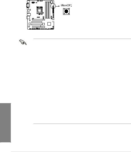
1.MemOK! button
Installing DIMMs that are not compatible with the motherboard may cause system boot failure, and the DRAM_LED near the MemOK! switch lights continuously. Press and hold the MemOK! button until the DRAM_LED starts blinking to begin automatic memory compatibility tuning for successful boot.
1 Chapter
Z97M-PLUS
Z97M-PLUS MemOK! button
• Refer to section 1.2.8 Onboard LEDs for the exact location of the DRAM_LED.
•The DRAM_LED also lights up when the DIMM is not properly installed. Turn off the system and reinstall the DIMM before using the MemOK! function.
•The MemOK! switch does not function under Windows® OS environment.
•During the tuning process, the system loads and tests failsafe memory settings. It takes about 30 seconds for the system to test one set of failsafe settings. If the test fails, the system reboots and test the next set of failsafe settings. The blinking speed of the DRAM_LED increases, indicating different test processes.
•Due to memory tuning requirement, the system automatically reboots when each timing set is tested. If the installed DIMMs still fail to boot after the whole tuning process, the DRAM_LED lights continuously. Replace the DIMMs with ones recommended in the Memory QVL (Qualified Vendors Lists) on the ASUS website at www.asus.com.
•If you turn off the computer and replace DIMMs during the tuning process, the system continues memory tuning after turning on the computer. To stop memory tuning, turn off the computer and unplug the power cord for about 5–10 seconds.
•If your system fails to boot up due to BIOS overclocking, press the MemOK! switch to boot and load the BIOS default settings. A message will appear during POST reminding you that the BIOS has been restored to its default settings.
•We recommend that you download and update to the latest BIOS version from the
ASUS website at www.asus.com after using the MemOK! function.
1-12 |
Chapter 1: Product introduction |
2.GPU Boost switch
With its two-level adjustment functions, the GPU Boost switch allows you to automatically adjusts the CPU Ratio and clock speed for an optimal system performance.
Z97M-PLUS
GPU Boost
|
GPU_I |
GPU_II |
Disable |
Enabled |
Enabled |
(Default) |
(GPU Boost and |
(GPU Boost and |
|
CPU Ratio Boost) |
CPU BCLK/Ratio |
|
|
Boost) |
Z97M-PLUS GPU Boost switch
• To ensure system performance, enable this switch when the system is powered off.
• When the GPU switch is set to Enabled (GPU_I: GPU Boost and CPU Ratio
Boost), the system automatically adjusts the GPU and CPU ratio for an enhanced performance.
•When the GPU switch is set to Enabled (GPU_II: GPU Boost and CPU BCLK/Ratio
Boost), the system automatically adjusts the GPU, base clock rate (BCLK) and the CPU ratio for a more enhanced performance.
•The GPU Boost LED near the GPU Boost switch lights up when the GPU Boost switch
is enabled. Refer to section 1.2.8 Onboard LEDs for the exact location of the GPU Boost LED.
•If you enable this switch under the Windows® OS environment, the GPU Boost function will be activated after the next system bootup.
•You may use the TurboV feature in the AI Suite 3 application, adjust the BIOS setup program or enable the GPU Boost switch at the same time. However, the system will use the last setting you have made.
Chapter 1
ASUS Z97M-PLUS |
1-13 |
1.2.8Onboard LEDs
1.Standby Power LED
The motherboard comes with a standby power LED that lights up to indicate that the system is ON, in sleep mode, or in soft-off mode. This is a reminder that you should shut down the system and unplug the power cable before removing or plugging in any motherboard component. The illustration below shows the location of the onboard LED.
1 Chapter
Z97M-PLUS
 SB_PWR
Z97M-PLUS Onboard LED
2.DRAM LED
DRAM LED checks the DRAM in sequence during motherboard booting process. If an error is found , the LED next to the error device will continue lighting until the problem is solved. This user-friendly design provides an intuitional way to locate the root problem within a second.
DRAM LED |
Z97M-PLUS
Z97M-PLUS DRAM LED
3.GPU Boost LED
The GPU Boost LED lights up when the GPU Boost switch is enabled.
 GPU_LED
Z97M-PLUS
Z97M-PLUS GPU Boost LED
1-14 |
Chapter 1: Product introduction |
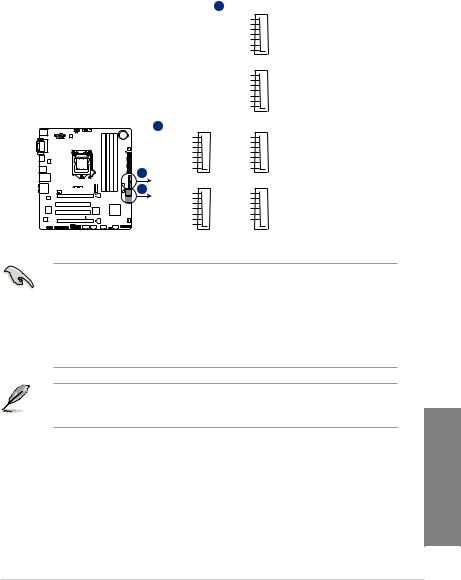
1.2.9Internal connectors
1.Intel® Z97 Serial ATA 6.0 Gb/s connectors (7-pin SATA6G_1-6)
These connectors connect to Serial ATA 6.0 Gb/s hard disk drives via Serial ATA 6.0 Gb/s signal cables.
If you installed Serial ATA hard disk drives, you can create a RAID 0, 1, 5, and 10 configuration with the Intel® Rapid Storage Technology through the onboard Intel® Z97 chipset.
A SATA6G_1
GND
RSATA_TXP1
RSATA_TXN1
GND
RSATA_RXN1
RSATA_RXP1
GND
SATA6G_2
GND
RSATA_TXP2
RSATA_TXN2
GND
RSATA_RXN2
RSATA_RXP2
GND
|
A |
Z97M-PLUS |
B |
B |
SATA6G_3 |
SATA6G_4 |
|
GND |
GND |
|
RSATA_TXP3 |
RSATA_TXP4 |
|
RSATA_TXN3 |
RSATA_TXN4 |
|
GND |
GND |
|
RSATA_RXN3 |
RSATA_RXN4 |
|
RSATA_RXP3 |
RSATA_RXP4 |
|
GND |
GND |
SATA6G_5 |
SATA6G_6 |
GND |
GND |
RSATA_TXP5 |
RSATA_TXP6 |
RSATA_TXN5 |
RSATA_TXN6 |
GND |
GND |
RSATA_RXN5 |
RSATA_RXN6 |
RSATA_RXP5 |
RSATA_RXP6 |
GND |
GND |
Z97M-PLUS SATA 6.0Gb/s connectors
•These connectors are set to [AHCI] by default. If you intend to create a Serial ATA RAID set using these connectors, set the SATA Mode Selection item in the BIOS to
[RAID]. Refer to section 3.6.3 PCH Storage Configuration for details.
•Before creating a RAID set, refer to section 5.1 RAID configurations or the manual bundled in the motherboard support DVD.
•When using hot-plug and NCQ, set the type of the SATA connectors in the BIOS to
[AHCI]. See section 3.6.3 PCH Storage Configuration for details.
M.2 Socket 3 shares the bandwidth with SATA ports 5 and 6. To ensure that the M.2 PCIe device is working properly, SATA ports 5 and 6 are disabled. See section 3.6.3 PCH Storage Configuration of this user guide for more details.
Chapter 1
ASUS Z97M-PLUS |
1-15 |
1 Chapter
2.USB 3.0 connector (20-1 pin USB3_12)
This connector allows you to connect a USB 3.0 module for additional USB 3.0 front or rear panel ports. With an installed USB 3.0 module, you can enjoy all the benefits of
USB 3.0 including faster data transfer speeds of up to 5Gbps, faster charging time for
USB-chargeable devices, optimized power efficiency, and backward compatibility with
USB 2.0.
|
USB3_12 |
|
|
|
PIN 1 |
|
|
USB3+5V |
|
USB3+5V |
IntA_P1_SSRX- |
|
IntA_P2_SSRX- |
IntA_P1_SSRX+ |
|
IntA_P2_SSRX+ |
GND |
|
GND |
IntA_P1_SSTX- |
Z97M-PLUS |
IntA_P2_SSTX- |
IntA_P1_SSTX+ |
|
IntA_P2_SSTX+ |
GND |
|
GND |
IntA_P1_D- |
|
IntA_P2_D- |
IntA_P1_D+ |
|
IntA_P2_D+ |
GND |
Z97M-PLUS USB3.0 Front panel connector
• The USB 3.0 module is purchased separately.
• These connectors are based on xHCI specification. We recommend you to install the related driver to fully use the USB 3.0 ports under Windows® 7.
•The plugged USB 3.0 device may run on xHCI or EHCI mode depending on the operating system’s setting.
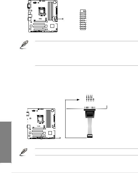
3.Serial port connector (10-1 pin COM)
This connector is for a serial (COM) port. Connect the serial port module cable to this connector, then install the module to a slot opening at the back of the system chassis.
COM
|
|
|
|
|
|
|
|
|
|
|
|
|
|
|
|
|
|
|
|
|
|
RXD DTR DSR CTS |
||
|
|
|
|
|
|
|
|
|
|
|
|
|
|
|
|
|
|
|
|
|
|
|
|
|
|
|
|
|
|
|
|
|
|
|
|
|
|
|
|
|
|
|
|
|
|
|
|
|
|
|
|
|
|
|
|
|
|
|
|
|
|
|
|
|
|
|
|
|
|
PIN 1 |
DCD TXD GND RTS RI |
|||
|
|
|
|
|
|
|
|
|
|
|
|
|
|
|
|
|
|
|
|
|
|
|||
|
|
|
|
|
|
|
|
|
|
|
|
|
|
|
|
|
|
|
|
|
|
|
|
|
|
|
|
|
|
|
|
|
|
|
|
|
|
|
|
|
|
|
|
|
|
|
|
|
|
|
|
|
|
|
|
|
|
|
|
|
|
|
|
|
|
|
|
|
|
|
|
|
|
|
|
|
|
|
|
|
|
|
|
|
|
|
|
|
|
|
|
|
|
|
|
|
|
|
|
|
|
|
|
|
|
|
|
|
|
|
|
|
|
|
|
|
|
|
|
|
|
|
|
|
Z97M-PLUS
Z97M-PLUS Serial port (COM) connector
The COM module is purchased separately.
1-16 |
Chapter 1: Product introduction |
Loading...