


Fatal1ty X470 Gaming K4
Table of contents
 Loading...

Version 1.0
Published January 2018
Copyright©2018 ASRock INC. All rights reserved.
Copyright Notice:
No part of this documentation may be reproduced, transcribed, transmitted, or
translated in any language, in any form or by any means, except duplication of
documentation by the purchaser for backup purpose, without written consent of
ASRock Inc.
Products and corporate names appearing in this documentation may or may not
be registered trademarks or copyrights of their respective companies, and are used
only for identication or explanation and to the owners’ benet, without intent to
infringe.
Disclaimer:
Specications and information contained in this documentation are furnished for
informational use only and subject to change without notice, and should not be
constructed as a commitment by ASRock. ASRock assumes no responsibility for
any errors or omissions that may appear in this documentation.
With respect to the contents of this documentation, ASRock does not provide
warranty of any kind, either expressed or implied, including but not limited to
the implied warranties or conditions of merchantability or tness for a particular
purpose.
In no event shall ASRock, its directors, ocers, employees, or agents be liable for
any indirect, special, incidental, or consequential damages (including damages for
loss of prots, loss of business, loss of data, interruption of business and the like),
even if ASRock has been advised of the possibility of such damages arising from any
defect or error in the documentation or product.
is device complies with Part 15 of the FCC Rules. Operation is subject to the following
two conditions:
(1) this device may not cause harmful interference, and
(2) this device must accept any interference received, including interference that
may cause undesired operation.
CALIFORNIA, USA ONLY
e Lithium battery adopted on this motherboard contains Perchlorate, a toxic substance
controlled in Perchlorate Best Management Practices (BMP) regulations passed by the
California Legislature. When you discard the Lithium battery in California, USA, please
follow the related regulations in advance.
“Perchlorate Material-special handling may apply, see ww w.dtsc.ca.gov/hazardouswaste/
perchlorate”
ASRock Website: http://www.asrock.com

AUSTRALIA ONLY
Our goods come with guarantees that cannot be excluded under the Australian Consumer
Law. You are entitled to a replacement or refund for a major failure and compensation for
any other reasonably foreseeable loss or damage caused by our goods. You are also entitled
to have the goods repaired or replaced if the goods fail to be of acceptable quality and the
failure does not amount to a major failure. If you require assistance please call ASRock Tel
: +886-2-28965588 ext.123 (Standard International call charges apply)
e terms HDMI™ and HDMI High-Denition Multimedia Interface, and the HDMI
logo are trademarks or registered trademarks of HDMI Licensing LLC in the United
States and other countries.

Who knew that at age 19, I would be a World Champion PC gamer. When I was 13, I actually
played competitive billiards in professional tournaments and won four or ve games o guys
who played at the highest level. I actually thought of making a career of it, but at that young
age situations change rapidly. Because I’ve been blessed with great hand-eye coordination and
a grasp of mathematics (an important element in video gaming) I gravitated to that activity.
GOING PRO
I started professional gaming in 1999 when I entered the CPL (Cyberathlete Professional
League) tournament in Dallas and won $4,000 for coming in third place. Emerging as one
of the top players in the United States, a company interested in sponsoring me ew me to
Sweden to compete against the top 12 players in the world. I won 18 straight games, lost
none, and took rst place, becoming the number one ranked Quake III player in the world
in the process. Two months later I followed that success by traveling to Dallas and defending
my title as the world’s best Quake III player, winning the $40,000 grand prize. From there
I entered competitions all over the world, including Singapore, Korea, Germany, Australia,
Holland and Brazil in addition to Los Angeles, New York and St. Louis.
WINNING STREAK
I was excited to showcase my true gaming skills when defending my title as CPL
Champion of the year at the CPL Winter 2001 because I would be competing in a totally
dierent rst person shooter (fps) game, Alien vs. Predator II. I won that competition and
walked away with a new car. e next year I won the same title playing Unreal Tournament
2003, becoming the only three-time CPL champion of the year. And I did it playing a
different game each year, something no one else has ever done and a feat of which I am
extremely proud.
At QuakeCon 2002, I faced o against my rival ZeRo4 in one of the most highly
anticipated matches of the year, winning in a 14 to (-1) killer victory. Competing at Quakecon
2004, I became the World’s 1st Doom3 Champion by defeating Daler in a series of very
challenging matches and earning $25,000 for the victory.
Since then Fatal1ty has traveled the globe to compete against the best in the world, winning
prizes and acclaim, including the 2005 CPL World Tour Championship in New York City for
a $150,000 rst place triumph. In August 2007, Johnathan was awarded the rst ever Lifetime
Achievement Award in the four year history of the eSports-Award for “showing exceptional
sportsmanship, taking part in shaping eSports into what it is today and for being the prime
representative of this young sport. He has become the gurehead for eSports worldwide”.
Fatal1ty Story

LIVIN’ LARGE
Since my rst big tournament wins, I have been a “Professional Cyberathlete”, traveling the
world and livin’ large with lots of International media coverage on outlets such as MTV,
ESPN and a 60 Minutes segment on CBS to name only a few. It's unreal - it's crazy. I’m living
a dream by playing video games for a living. I’ve always been athletic and took sports like
hockey and football very seriously, working out and training hard. is discipline helps me
become a better gamer and my drive to be the best has opened the doors necessary to become
a professional.
A DREAM
Now, another dream is being realized – building the ultimate gaming computer, made
up of the best parts under my own brand. Quality hardware makes a huge difference in
competitions…a couple more frames per second and everything gets really nice. It’s all about
getting the computer processing faster and allowing more uid movement around the maps.
My vision for Fatal1ty hardware is to allow gamers to focus on the game without worrying
about their equipment, something I’ve preached since I began competing. I don’t want to
worry about my equipment. I want to be there – over and done with - so I can focus on
the game. I want it to be the fastest and most stable computer equipment on the face of the
planet, so quality is what Fatal1ty Brand products represent.
Johnathan “Fatal1ty” Wendel
e Fatal1ty name, Fatal1ty logos and the Fatal1ty likeness are registered trademarks of Fatal1ty, Inc., and are used
under license. © 2018 Fatal1ty, Inc. All rights reserved. All other trademarks are the property of their respective
owners.

Contents
Chapter 1 Introduction 1
1.1 Package Contents 1
1.2 Specications 2
1.3 Motherboard Layout 7
1.4 I/O Panel 9
Chapter 2 Installation 11
2.1 Installing the CPU 12
2.2 Installing the CPU Fan and Heatsink 14
2.3 Installing Memory Modules (DIMM) 23
2.4 Expansion Slots (PCI Express Slots) 26
2.5 Jumpers Setup 27
2.6 Onboard Headers and Connectors 28
2.7 Dr. Debug 34
2.8 SLI
TM
and Quad SLI
TM
Operation Guide 36
2.8.1 Installing Two SLI
TM
-Ready Graphics Cards 36
2.8.2 Driver Installation and Setup 38
2.9 CrossFireX
TM
and Quad CrossFireX
TM
Operation Guide 39
2.9.1 Installing Two CrossFireX
TM
-Ready Graphics Cards 39
2.9.2 Driver Installation and Setup 41
2.10 M.2_SSD (NGFF) Module Installation Guide (M2_1) 42
2.11 M.2_SSD (NGFF) Module Installation Guide (M2_2) 45
Chapter 3 Software and Utilities Operation 48

3.1 Installing Drivers 48
3.2 F-Stream 49
3.2.1 Installing F-Stream 49
3.2.2 Using F-Stream 49
3.3 ASRock Live Update & APP Shop 52
3.3.1 UI Overview 52
3.3.2 Apps 53
3.3.3 BIOS & Drivers 56
3.3.4 Setting 57
3.4 Creative SoundBlaster Cinema5 58
3.5 ASRock Polychrome RGB 59
Chapter 4 UEFI SETUP UTILITY 62
4.1 Introduction 62
4.1.1 UEFI Menu Bar 62
4.1.2 Navigation Keys 63
4.2 Main Screen 64
4.3 OC Tweaker Screen 65
4.4 Advanced Screen 68
4.4.1 CPU Conguration 69
4.4.2 North Bridge Conguration 70
4.4.3 South Bridge Conguration 71
4.4.4 Storage Conguration 72
4.4.5 Super IO Conguration 73
4.4.6 ACPI Conguration 74

4.4.7 Trusted Computing 75
4.4.8 AMD CBS 76
4.4.9 AMD PBS 84
4.5 Tools 85
4.6 Hardware Health Event Monitoring Screen 87
4.7 Security Screen 90
4.8 Boot Screen 91
4.9 Exit Screen 93

English
1
Fatal1ty X470 Gaming K4 Series
Chapter 1 Introduction
ank you for purchasing ASRock Fatal1ty X470 Gaming K4 Series motherboard,
a reliable motherboard produced under ASRock ’s consistently stringent quality
control. It delivers excellent performance with robust design conforming to
ASRock’s commitment to quality and endurance.
In this documentation, Chapter 1 and 2 contains the introduction of the
motherboard and step-by-step installation guides. Chapter 3 contains the operation
guide of the soware and utilities. Chapter 4 contains the conguration guide of
the BIOS setup.
1.1 Package Contents
•
ASRock Fatal1ty X470 Gaming K4 Series Motherboard (ATX Form Factor)
•
ASRock Fatal1ty X470 Gaming K4 Series Quick Installation Guide
•
ASRock Fatal1ty X470 Gaming K4 Series Support CD
•
1 x I/O Panel Shield
•
4 x Serial ATA (SATA) Data Cables (Optional)
•
1 x ASRock SLI_HB_Bridge_2S Card (Optional)
•
2 x Screws for M.2 Sockets (Optional)
Becau se the motherboard specications and the BIOS soware might be updated, the
content of this documentation will be subject to change without notice. In case any
modications of this documentation occur, the updated version will be available on
ASRock’s website w ithout f urther notice. If you require technical support relate d to
this motherboard, please vi sit our website for s pecic information about the model
you are using. You may nd the l atest VGA cards and CPU suppor t list on ASRock’s
website a s well. ASRock website ht tp://www.a srock.com.

English
2
1.2 Specications
Platform
•
ATX Form Factor
•
2oz Copper PCB
CPU
•
Supports AMD AM4 Socket Ryzen Series CPUs (Summit
Ridge, Raven Ridge and Pinnacle Ridge)
•
Digi Power design
•
12 Power Phase design
•
Supports 105W Water Cooling (Pinnacle Ridge); Supports
95W Water Cooling (Summit Ridge); Supports 65W Water
Cooling (Raven Ridge)
Chipset
•
AMD Promontory X470
Memory
•
Dual Channel DDR4 Memory Technology
•
4 x DDR4 DIMM Slots
•
AMD Ryzen series CPUs (Pinnacle Ridge) support DDR4
3466+(OC)/3200(OC)/2933/2667/2400/2133 ECC & non-
ECC, un-buered memory*
•
AMD Ryzen series CPUs (Summit Ridge) support DDR4
3466+(OC)/3200(OC)/2933(OC)/2667/2400/2133 ECC &
non-ECC, un-buered memory*
•
AMD Ryzen series CPUs (Raven Ridge) support DDR4
3466+(OC)/3200(OC)/2933(OC)/2667/2400/2133 non-ECC,
un-buered memory*
* For Ryzen Series CPUs (Raven Ridge), ECC is only supported
with PRO CPUs.
* Please refer to Memory Support List on ASRock’s website for
more information. (http://www.asrock.com/)
* Please refer to page 23 for DDR4 UDIMM maximum
frequency support.
•
Max. capacity of system memory: 64GB
•
15μ Gold Contact in DIMM Slots
Expansion
Slot
•
2 x PCI Express 3.0 x16 Slots (single at x16 (PCIE1); dual at
x8 (PCIE1) / x8 (PCIE4))*
* Supports NVMe SSD as boot disks
•
4 x PCI Express 2.0 x1 Slots

English
3
Fatal1ty X470 Gaming K4 Series
•
Supports AMD Quad CrossFireX
TM
and CrossFireX
TM
•
Supports NVIDIA® Quad SLI
TM
and SLI
TM
•
15μ Gold Contact in VGA PCIe Slot (PCIE1)
Graphics
•
Integrated AMD Radeon
TM
Vega Series Graphics in Ryzen
Series APU*
* Actual support may vary by CPU
•
DirectX 12, Pixel Shader 5.0
•
Max. shared memory 2GB
•
Supports HDMI with max. resolution up to 4K x 2K
(4096x2160) @ 30Hz
•
Supports Auto Lip Sync, Deep Color (12bpc), xvYCC and
HBR (High Bit Rate Audio) with HDMI Port (Compliant
HDMI monitor is required)
•
Supports HDCP with HDMI Port
•
Supports 4K Ultra HD (UHD) playback with HDMI Port
Audio
•
7.1 CH HD Audio with Content Protection (Realtek
ALC1220 Audio Codec)
•
Premium Blu-ray Audio support
•
Supports Surge Protection
•
Nichicon Fine Gold Series Audio Caps
•
120dB SNR DAC with Dierential Amplier
•
NE5532 Premium Headset Amplier for Front Panel Audio
Connector (Supports up to 600 Ohm headsets)
•
Pure Power-In
•
Direct Drive Technology
•
PCB Isolate Shielding
•
Impedance Sensing on Line Out port
•
Individual PCB Layers for R/L Audio Channel
•
Gold Audio Jacks
•
Supports Creative SoundBlaster Cinema5
LAN
•
Gigabit LAN 10/100/1000 Mb/s
•
GigaLAN Intel® I211AT
•
Supports Wake-On-LAN
•
Supports Lightning/ESD Protection
•
Supports Energy Ecient Ethernet 802.3az
•
Supports PXE

English
4
Rear Panel
I/O
•
1 x PS/2 Mouse/Keyboard Port
•
1 x HDMI Port
•
1 x Optica l SPDIF Out Port
•
1 x USB 3.1 Gen2 Type-A Port (10 Gb/s) (Supports ESD
Protection)
•
1 x USB 3.1 Gen2 Type-C Port (10 Gb/s) (Supports ESD
Protection)
•
6 x USB 3.1 Gen1 Ports (Supports ESD Protection)
* 1 x Fatal1ty Mouse Port (USB 3.1 Gen1) is included
•
1 x RJ-45 LAN Port with LED (ACT/LINK LED and SPEED
LED)
•
HD Audio Jacks: Rear Speaker / Central / Bass / Line in /
Front Speaker / Microphone (Gold Audio Jacks)
Storage
•
6 x SATA3 6.0 Gb/s Connectors, support RAID (RAID 0,
RAID 1 and RAID 10), NCQ, AHCI and Hot Plug
•
1 x Ultra M.2 Socket (M2_1), supports M Key type
2230/2242/2260/2280/22110 M.2 SATA3 6.0 Gb/s module
and M.2 PCI Express module up to Gen3 x4 (32 Gb/s)*
•
1 x M.2 Socket (M2_2), supports M Key type
2230/2242/2260/2280 M.2 SATA3 6.0 Gb/s module and M.2
PCI Express module up to Gen2 x2 (10 Gb/s)*
* Supports NVMe SSD as boot disks
* Supports ASRock U.2 Kit
Connector
•
1 x COM Port Header
•
1 x TPM Header
•
1 x Power LED and Speaker Header
•
1 x AMD Fan LED Header
* e AMD Fan LED Header supports LED strips of maximum
load of 3A (36W) and length up to 2.5M.
•
1 x RGB LED Header
* Supports in total up to 12V/3A, 36W LED Strip
•
1 x Addressable LED Header
* Supports in total up to 5V/3A, 15W LED Strip
•
1 x CPU Fan Connector (4-pin)
* e CPU Fan Connector supports the CPU fan of ma ximum
1A (12W) fan power.
•
1 x CPU/Water Pump Fan Connector (4-pin) (Smart Fan
Speed Control)

English
5
Fatal1ty X470 Gaming K4 Series
* e CPU/Water Pump Fan supports the water cooler fan of
maximum 2A (24W) fan power.
•
3 x Chassis/Water Pump Fan Connectors (4-pin) (Smart Fan
Speed Control)
* e Chassis/Water Pump Fan supports the water cooler fan of
maximum 2A (24W) fan power.
* CPU_FAN2/WP, CHA_FAN1/WP, CHA_FAN2/WP and
CHA_FAN3/WP can auto detect if 3-pin or 4-pin fan is in use.
•
1 x 24 pin ATX Power Connector (Hi-Density Power Con-
nector)
•
1 x 8 pin 12V Power Connector (Hi-Density Power Connec-
tor)
•
1 x 4 pin 12V Power Connector (Hi-Density Power Connec-
tor)
•
1 x Front Panel Audio Connector
•
1 x AMD LED Fan USB Header
•
2 x USB 2.0 Headers (Support 4 USB 2.0 ports) (Supports
ESD Protection)
•
2 x USB 3.1 Gen1 Headers (Support 4 USB 3.1 Gen1 ports)
(Supports ESD Protection)
•
1 x Dr. Debug with LED
BIOS
Feature
•
AMI UEFI Legal BIOS with GUI support
•
Supports “Plug and Play”
•
ACPI 5.1 compliance wake up events
•
Supports jumperfree
•
SMBIOS 2.3 support
•
CPU, VCORE_NB, DRAM, VPPM, PCH 1.05V, +1.8V,
VDDP, PROM 2.5V, Voltage Multi-adjustment
Hardware
Monitor
•
Temperature Sensing: CPU, CPU/Water Pump, Chassis/Wa-
ter Pump Fans
•
Fan Tachometer: CPU, CPU/Water Pump, Chassis/Water
Pump Fans
•
Quiet Fan (Auto adjust chassis fan speed by CPU tempera-
ture): CPU, CPU/Water Pump, Chassis/Water Pump Fans
•
Fan Multi-Speed Control: CPU, CPU/Water Pump, Chassis/
Water Pump Fans
•
Voltage monitoring: +12V, +5V, +3.3V, CPU Vcore, VCORE_
NB, DRAM, PCH 1.05V, +1.8V, VDDP
English
6
OS
•
Microso® Windows® 10 64-bit
Certica-
tions
•
FCC, CE
•
ErP/EuP ready (ErP/EuP ready power supply is required)
Please realize that the re is a certain r isk involved with overclo cking, including
adjusting the setting in the BIOS, applying Untied Overclocking Technol ogy, or using
third-party overclocking tool s. Overclocking may aect your system’s stability, or
even cause dam age to the components and devices of your system. It should be done
at your own risk and expense. We are not responsible for poss ible damage caused by
overclocking.
* For detailed product information, please visit our website:
http://ww w.asrock.com
English
7
Fatal1ty X470 Gaming K4 Series
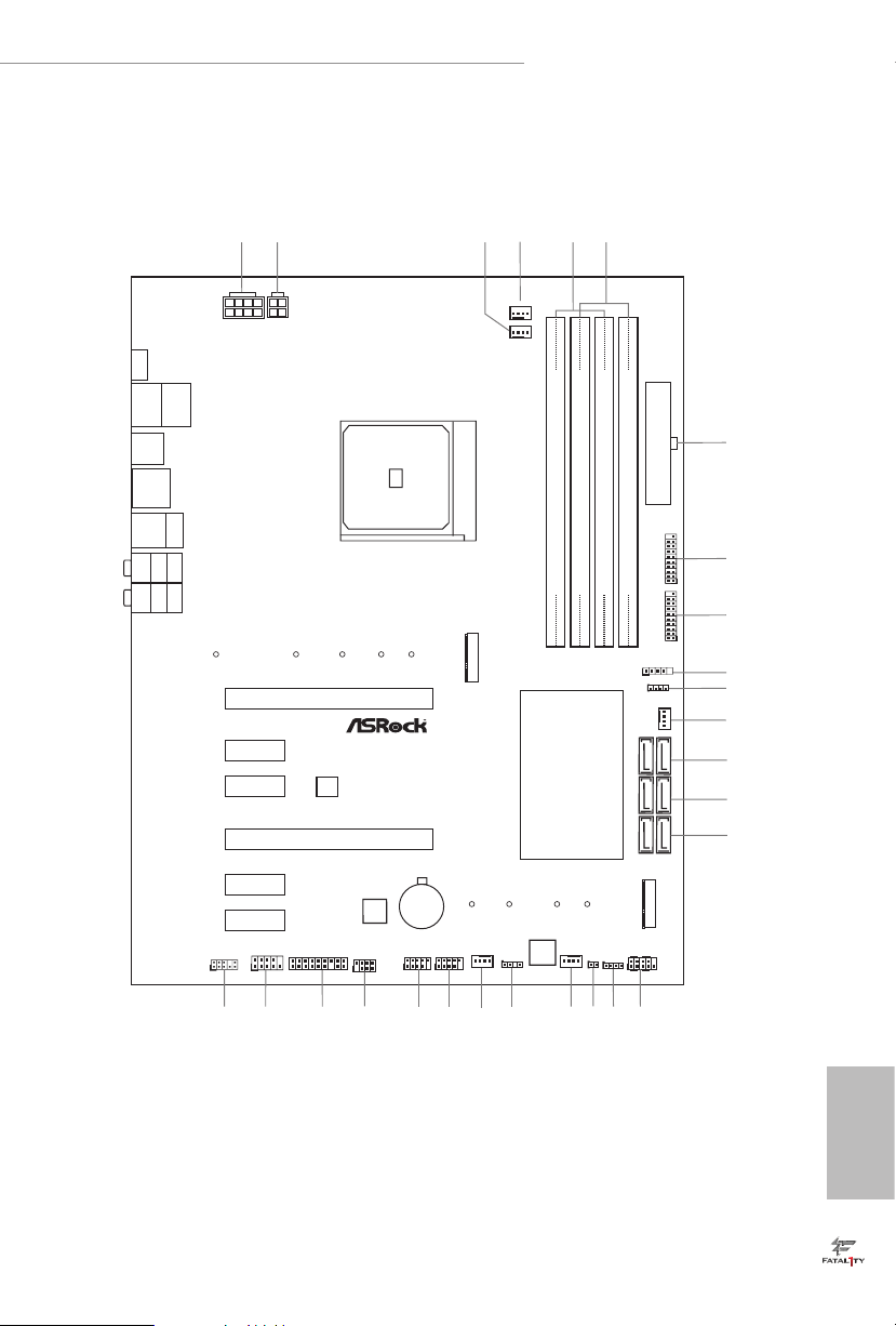
1.3 Motherboard Layout
DDR4 _A2 (64 bit, 288- pin modu le)
DDR4 _A1 (64 bit, 288- pin modu le)
DDR4 _B2 (64 bit, 288- pin modu le)
DDR4 _B1 (64 bit, 288- pin modu le)
ATXP WR 1
PCI E1
Top:
Central/Bass
Center:
REAR SPK
Top:
LINE IN
Center:
FRONT
Bottom:
Optical
SPDIF
Bottom:
MIC I N
PCI E4
HDLED RE SET
PLED PWRBTN
PANEL1
1
1
SPK_PLE D1
COM1
1
1
HD_AUDI O1
X470 Gami ng K4
SATA3_3_4
SATA3_1_2
6
12
13
14
USB_1_2
1
21
19
USB_3_4
1
22
25
26
SATA3_5_6
1
5
4
24
Dr.
Debug
15
CMOS
Batt ery
M2_1
M2_2
USB3_7_ 8
1
23
CPU_FAN1
7
8
9
10
11
1
TPMS1
Ult ra M .2
PCIe G en3 x4
FATAL TY
1
CHA_FAN1 /WP
3
2
USB3_9_ 10
1
AMD_FAN_L ED1
1
BIOS
ROM
RoH S
PCI E5
CHA_FAN2 /WP
16
1
USB_5
RGB_LED1
1
Super
I/O
PCI E6
CPU_FAN2 /WP
CHA_FAN3 /WP
20
Top:
RJ-45
USB 3.1G en1
T:USB 5
B:U SB6
USB 3.1 Gen2
T:US B3_TA_1
B: USB3_T C_1
USB 3.1 Gen1
T:US B3
B: U SB4
18
17
ADDR_LED 1
1
AMD
Promon to ry
X470
SOCKE T AM 4
HDMI1
PS2
Keybo ard/
Mouse
USB3 .1G en1
T:USB 1
B:U S B2
ATX12V1 ATX12 V2
CLRCMOS1
1
PCI E2
PCI E3
27

English
8
No. Description
1 ATX 12V Power Connector (ATX12V1)
2 ATX 12V Power Connector (ATX12V2)
3 CPU Fan Connector (CPU_FAN1)
4 CPU/Water Pump Fan Connector (CPU_FAN2/WP)
5 2 x 288-pin DDR4 DIMM Slots (DDR4_A1, DDR4_B1)
6 2 x 288-pin DDR4 DIMM Slots (DDR4_A2, DDR4_B2)
7 ATX Power Connector (ATXPWR1)
8 USB 3.1 Gen1 Header (USB3_9_10)
9 USB 3.1 Gen1 Header (USB3_7_8)
10 AMD LED Fan USB Header (USB_5)
11 AMD Fan LED Header (AMD_FAN_LED1)
12 Chassis/Water Pump Fan Connector (CHA_FAN1/WP)
13 SATA3 Connectors (SATA3_5_6)
14 SATA3 Connectors (SATA3_3_4)
15 SATA3 Connectors (SATA3_1_2)
16 System Panel Header (PANEL1)
17 RGB LED Header (RGB_LED1)
18 Clear CMOS Jumper (CLRCMOS1)
19 Chassis/Water Pump Fan Connector (CHA_FAN2/WP)
20 Addressable LED Header (ADDR_LED1)
21 Chassis/Water Pump Fan Connector (CHA_FAN3/WP)
22 USB 2.0 Header (USB_1_2)
23 USB 2.0 Header (USB_3_4)
24 Power LED and Speaker Header (SPK_PLED1)
25 TPM Header (TPMS1)
26 COM Port Header (COM1)
27 Front Panel Audio Header (HD_AUDIO1)
English
9
Fatal1ty X470 Gaming K4 Series
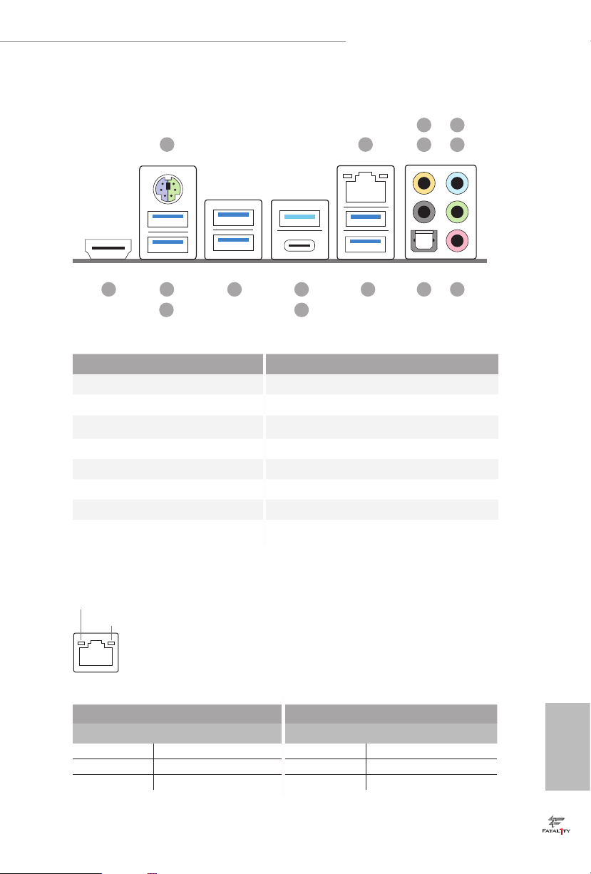
1.4 I/O Panel
No. Description No. Description
1 PS/2 Mouse/Keyboard Port 9 USB 3.1 Gen1 Ports (USB3_5_6)
2 LAN RJ-45 Port* 10 USB 3.1 Gen2 Type-A Port (USB3_TA_1)
3 Central / Bass (Orange) 11 USB 3.1 Gen2 Type-C Port (USB3_TC_1)
4 Rear Speaker (Black) 12 USB 3.1 Gen1 Ports (USB3_3_4)
5 Line In (Light Blue) 13 Fatal1ty Mouse Port (USB3_1)
6 Front Speaker (Lime)** 14 USB 3.1 Gen1 Port (USB3_2)
7 Microphone (Pink) 15 HDMI Port (HDMI1)
8 Optica l SPDIF Out Port
* ere are two LEDs on each LAN port. Please refer to the table below for the LAN port LED indications .
Activity / Link LED Speed LED
Status Description Status Description
O No Link O 10Mbps connection
Blinking Data Activity Orange 100Mbps connection
On Link Green 1Gbps connection
ACT/LINK L ED
SPEED LE D
LAN Por t
1
12 91015 13
2
11
78
4
3
6
5
14

English
10
** If you use a 2- channel speaker, plea se connect the speake r’s plug into “Front Speaker Jack”. See the table below
for connection d etails in accordance w ith the type of speaker you use.
Audio Output
Channels
Front Speaker
(No. 6)
Rear Speaker
(No. 4)
Central / Bass
(No. 3)
Line In
(No. 5)
2 V -- -- --
4 V V -- --
6 V V V --
8 V V V V

English
11
Fatal1ty X470 Gaming K4 Series
is is an ATX form factor motherboard. Before you install the motherboard, study
the conguration of your chassis to ensure that the motherboard ts into it.
Pre-installation Precautions
Take note of the following precautions before you install motherboard components
or change any motherboard settings.
•
Make sure to unplug the power cord before installing or removing the motherboard.
Failure to do so may cause physical injuries to you and damages to motherboard
components.
•
In order to avoid damage from static electricity to the motherboard’s components,
NEVER place your motherboard directly on a carpet. Also remember to use a grounded
wrist strap or touch a safety grounded object before you handle the components.
•
Hold components by the edges and do not touch the ICs.
•
Whenever you uninstall any components, place them on a grounded anti-static pad or
in the bag that comes with the components.
•
When placing screws to secure the motherboard to the chassis, please do not over-
tighten the screws! Doing so may damage the motherboard.
Chapter 2 Installation
English
12
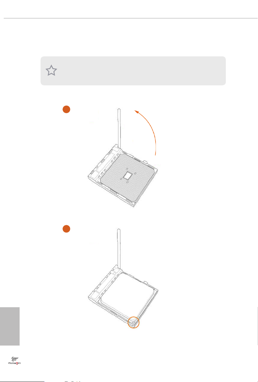
2.1 Installing the CPU
Unplug all power cables be fore installing the CPU.
2
1

English
13
Fatal1ty X470 Gaming K4 Series
3
English
14
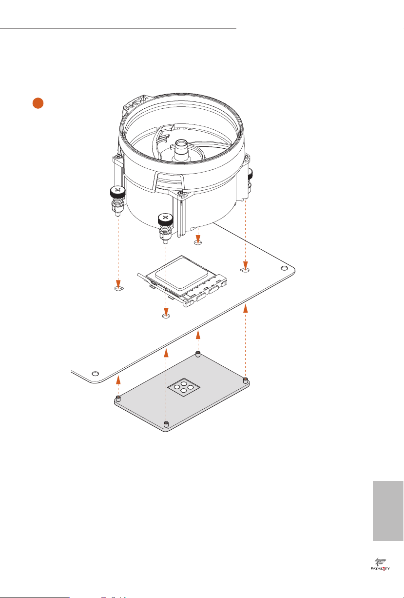
2.2 Installing the CPU Fan and Heatsink
Aer you install the CPU into this motherboard, it is necessary to install a larger
heatsink and cooling fan to dissipate heat. You also need to spray thermal grease
between the CPU and the heatsink to improve heat dissipation. Ma ke sure that the
CPU and the heatsink are securely fastened and in good contact with each other.
Installing the CPU Box Cooler SR1
Please turn o the power or remove the power cord before changing a CPU or heatsink.
1
2
English
15
Fatal1ty X470 Gaming K4 Series
3
4
C
P
U
_
FA
N
1
English
16
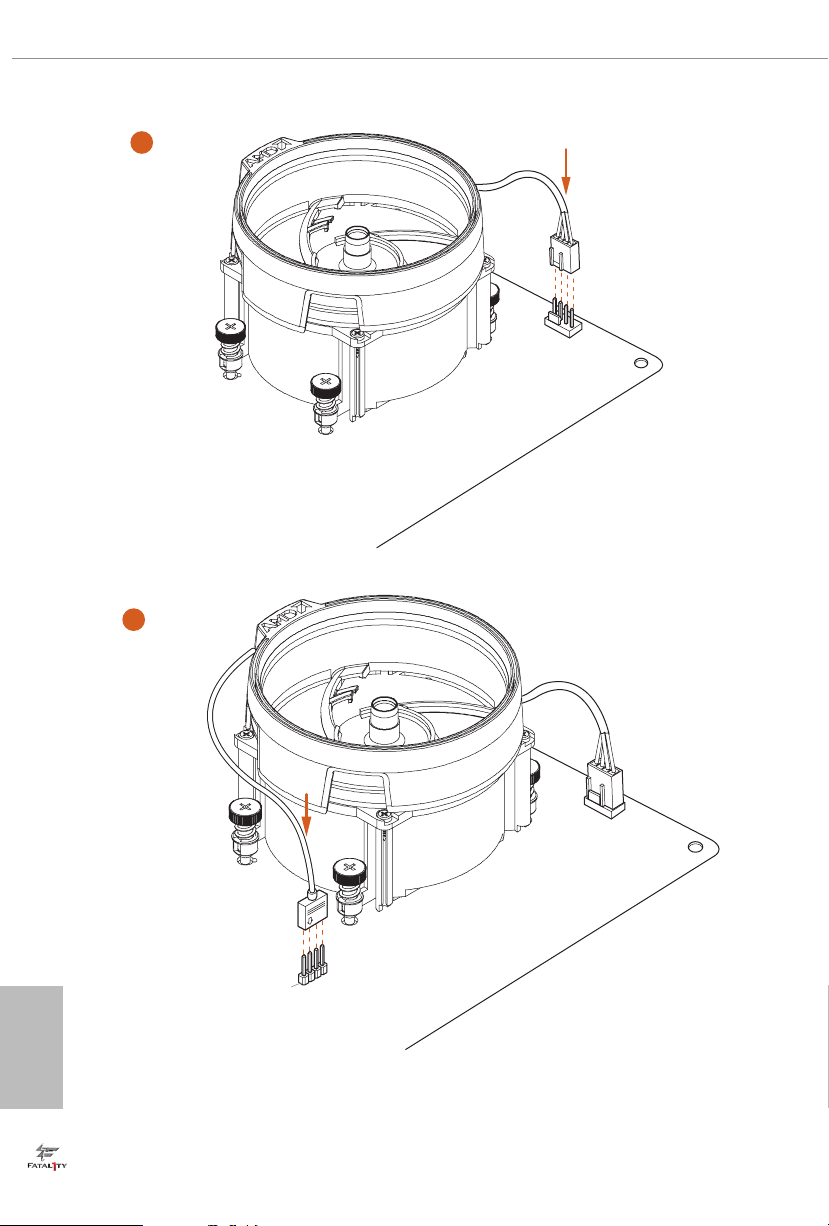
Installing the AM4 Box Cooler SR2
1
2
English
17
Fatal1ty X470 Gaming K4 Series
3
English
18
4-pin FAN cable
RGB LED Cable
+12V
*e diagram shown here are for reference only. Please refer to page 32 for the orientation of
AMD Fan LED Header (AMD_FAN_LED1).
5
CPU_
FA
N
1
AM
D
_
FA
N
_
L
E
D
1
4
C
P
U
_
FA
N
1
English
19
Fatal1ty X470 Gaming K4 Series
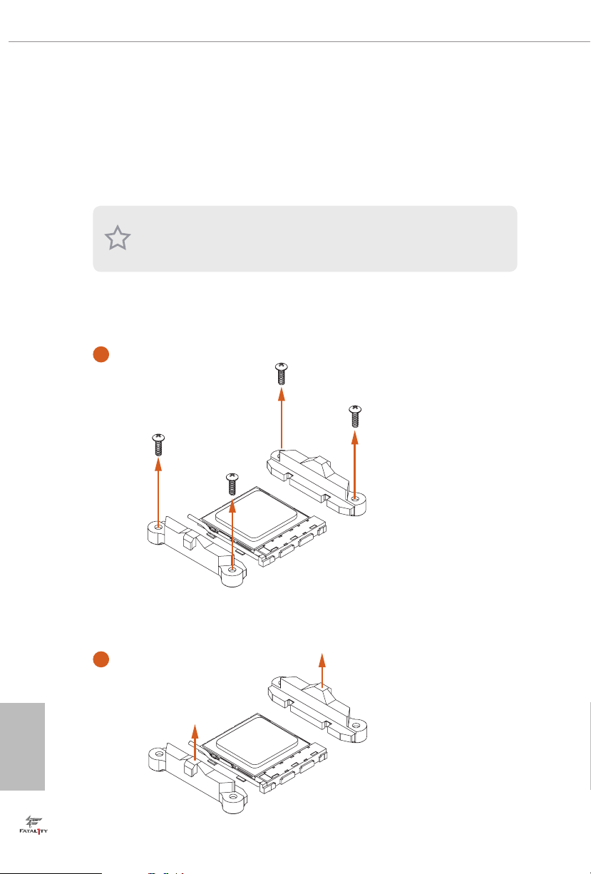
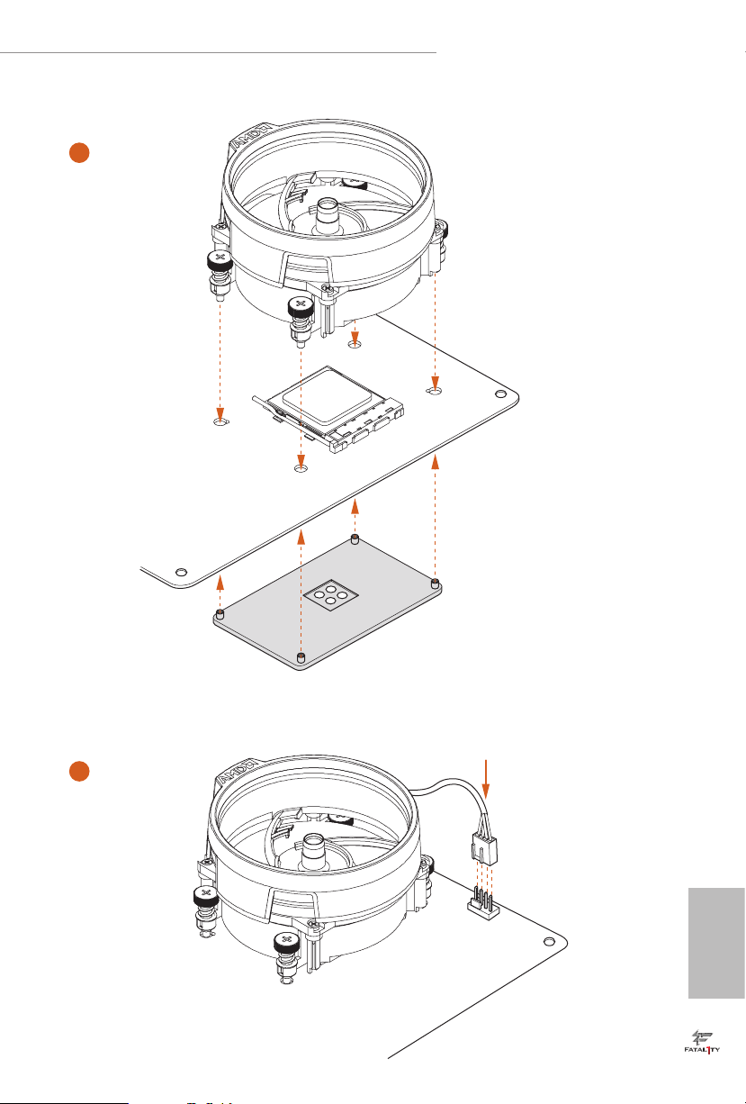
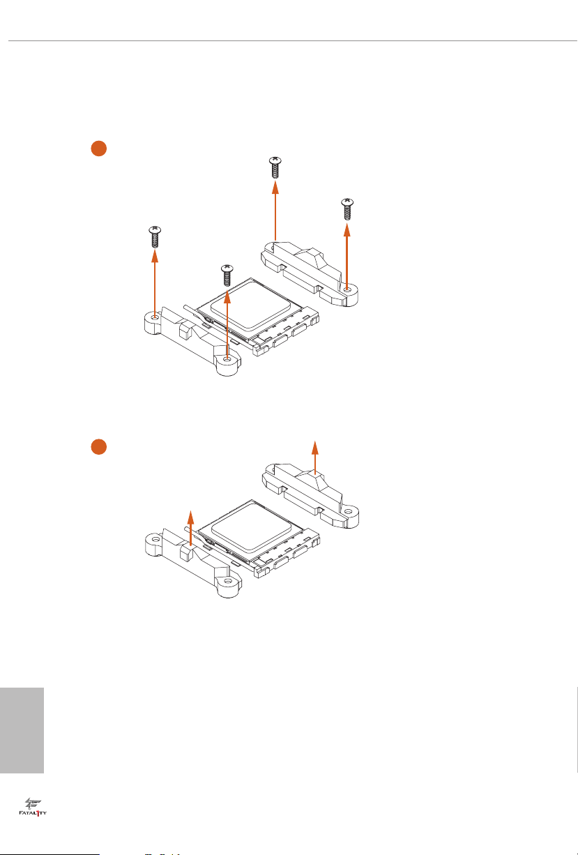
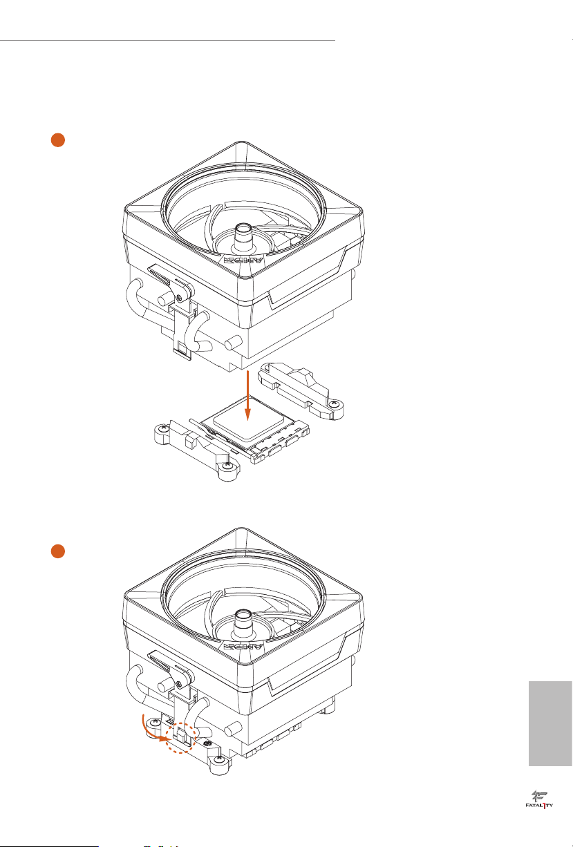
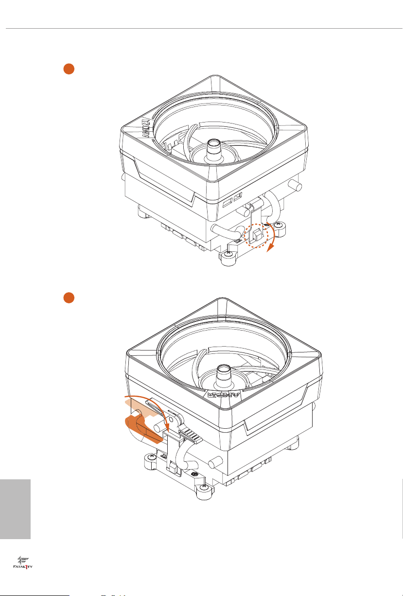
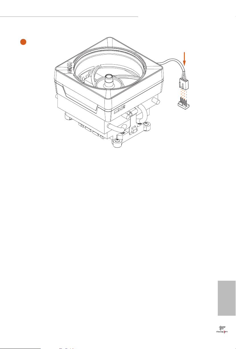
Installing the AM4 Box Cooler SR3
1
2
English
20
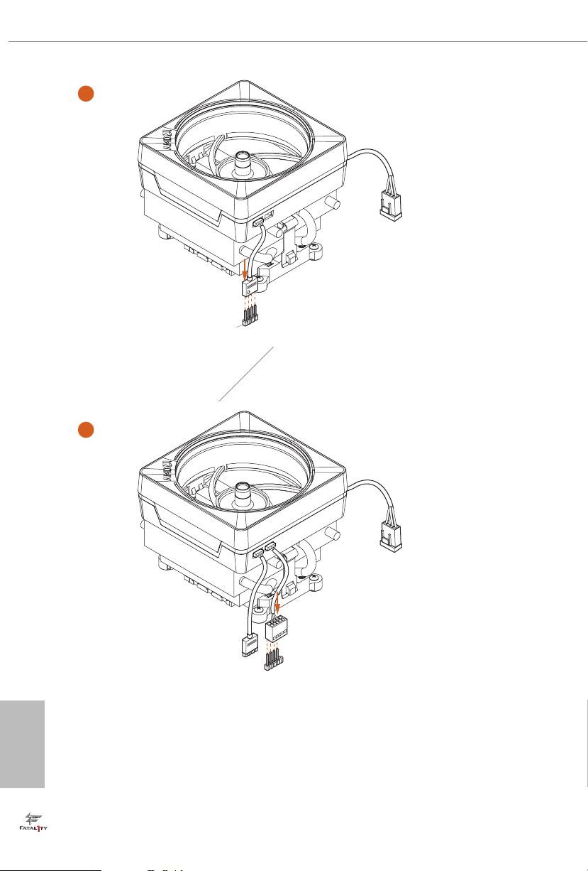
3
4
English
21
Fatal1ty X470 Gaming K4 Series
5
CPU_FAN1
English
22
Please note that only one cable should be used at a time in this step.
If you select AMD_FAN_LED1, please install ASRock utility "ASRock Polychrome RGB".
If you select USB connector, please install AMD utility "SR3 Settings So ware".
*e diagram shown here are for reference only. Please refer to page 32 for the orientation of AMD Fan
LED Header (AMD_FAN_LED1) and page 29 for the orientation of AMD LED Fan USB Header (USB_5).
7
6
C
P
U
_
FA
N
1
AM
D
_
FA
N
_
L
E
D
1
C
P
U
_
FA
N
1
AM
D
_
FA
N
_
L
E
D
1
U
S
B
_
5
or
+12V
Loading...