


Users Guide
Installation and Servicing Instructions
TP 23 - G.C. Number 47-116-32
TP 30 - G.C. Number 47-116-33
Manufacturered by Merloni TermoSanitari spa - Italy
Country of destination: GB - IE

TABLE OF CONTENTS
USERS GUIDE
1.GENERAL INFORMATION
2.OPERATING INSTRUCTIONS
3.BOILER SHUTDOWN SITUATIONS
4.TIME CLOCK
INSTALLATION AND SERVICING INSTRUCTIONS
5.GENERAL INFORMATION
5.1General Instructions
5.2Overall View
6.INSTALLATION
6.1Reference Standards
6.2Siting the Appliance
6.3Overall Dimensions
6.4Clearances
6.5Mounting the Appliance
6.6Electrical Connection
6.7Gas Connection
6.8Water Connections
6.9Flue Connection
6.10Control Panel
6.11Removing the front panel
6.12Fitting the Time Clock
6.13Room Thermostat Connection
6.14Electrical/System Diagrams
6.15Water Circuit Diagram
7.COMMISSIONING
7.1Initial Preparation
7.2Initial Start up
7.3Operational Adjustments
7.4Combustion Analysis
7.5Product of Combustion Discharge Monitoring
7.6Boiler Safety Systems
7.7Draining the System
7.8Completion
7.9Operational checks
7.10Instructing the End User
8.GAS ADJUSTMENTS
8.1Changing the Type of Gas
8.2Adjusting the gas pressure
9.MAINTENANCE
10. SERVICING INSTRUCTIONS
10.1Replacement of Parts
10.2To Gain General Access
10.2.1Removing the Front Panel
10.2.2Removing the Sealed Chamber Front Panel
10.2.3Removing the Side Panels
10.3Access to the Combustion Chamber
10.3.1Removing the Combustion Cover
10.3.2Removing the Burner and Jets
10.3.3Removing the Electrodes
10.3.4Removing the Main Heat Exchanger
10.3.5Removing the Air Pressure Switch
10.3.6Removing the Fan
10.4Access to the Gas Valve
10.4.1Removing the Spark Generator
10.4.2Removing the Gas Valve
10.5Access to the Water Circuit
10.5.1Removing the D.H.W. (secondary) exchanger
10.5.2Removing the Pump Pressure Switch
10.5.3Removing the Safety Valve
10.5.4Removing the Automatic Air Vent
10.5.5Removing the Pump
10.5.6Removing the Pressure Gauge
10.5.7Removing the Expansion Vessel
10.5.8Removing the Overheat Thermostat
10.5.9Removing the Central Heating Temperature Sensor (N.T.C.)
10.5.10Removing the D.H.W.Temperature Sensor (N.T.C.) 10.5.11Removing the D.H.W. Flow Switch 10.5.12Removing the Divertor Valve Actuator
10.6Access to the Control System
10.6.1Checking the Fuses
10.6.2Removing the Time Clock
10.6.3Removing the P.C.B.
11. FAULT FINDING
11.1 Fault Finding Guide (Flow-chart)
12.SHORT SPARE PARTS LIST
13.TECHNICAL INFORMATION
2
USERS GUIDE
1. General Information |
2. Operating Instructions |
|
|
This is a combined appliance for the production of central heating (C.H.) and domestic hot water (D.H.W.). This appliance must be used only for the purpose for which it is designed. The manufacturer declines all liability for damage caused by improper or negligent use.
Do not allow children or inexperienced persons to use the appliance without supervision.
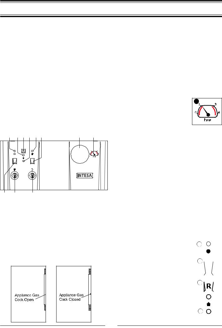
If you smell gas in the room, do not turn on light switches, use the telephone or any other object which might cause sparks. Open doors and windows immediately to ventilate the room. Shut the gas mains tap (on the gas meter) or the valve of the gas cylinder and call your Gas Supplier immediately.
If you are going away for a long period of time, remember to shut the mains gas tap or the gas cylinder valve.
Before any intervention within the boiler it is first necessary to cut off the electrical power supply by turning the external switch to “OFF”.
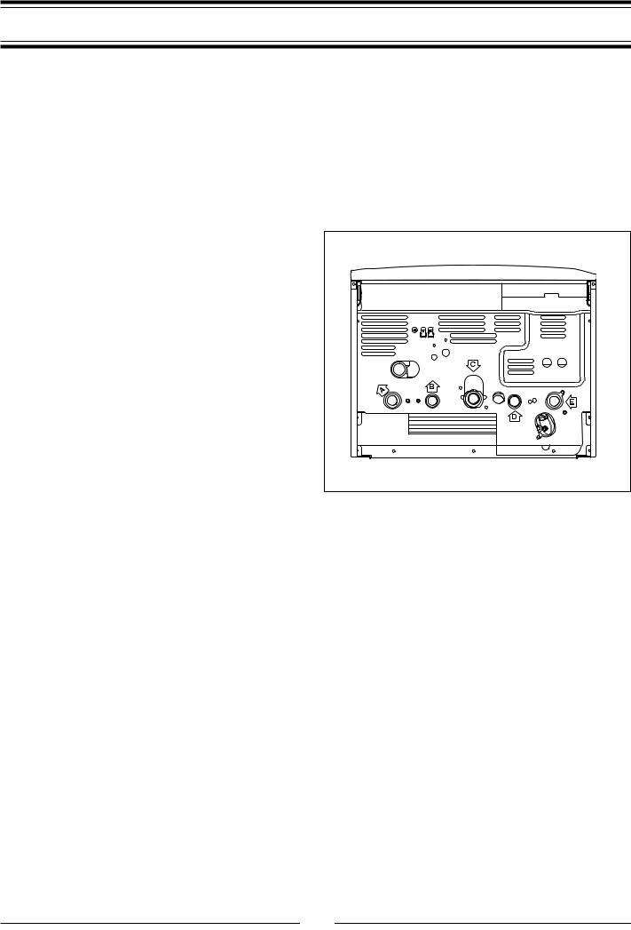
Control Panel
K J I H G F E D
A B C
LEGEND:
A- On/Off button
B- Central heating temperature adjustment
C- Domestic hot water temperature adjustment
D- Heating system pressure gauge
E- Time clock
F- Central heating selector
G- Central heating L.E.D. (green)
H- Flue sensor L.E.D. (yellow)
I- Ignition failure (lockout) and/or overheat reset button
J- Overheat and/or ignition failure (lockout) L.E.D. (red)
K- ON/OFF L.E.D. (green)
Installation, start-up, adjustments and maintenance must be performed by a competent person only, in accordance with the current Gas Safety (Installation & Use) Regulations and the instructions provided. Improper installation may cause damage or injury to individuals, animals and personal property, for which the manufacturer will not be held liable.
To ensure efficient and safe operation it is recommended that the boiler is serviced annually by a competent person. If it is known or suspected that a fault exists on the appliance, it must not be used until the fault has been corrected by a competent person.
To get the most out of your boiler, we have provided you with |
||
some useful advice on proper use and maintenance: |
||
- Periodically check the system pressure |
D |
|
using the pressure gauge “D” , make sure |
||
|
||
that the pressure is at 1.5 bar when the sys- |
|
|
tem is off and cool. If the pressure is below |
|
|
the minimum recommended value. |
|
|
Consult your installer for checking and refill- |
|
|
ing the system. |
|
|
-The outer panels of the units case must only be cleaned with a damp cloth. Do not use abrasive cleaners. The control panel can be wiped with either a damp or dry cloth. Spray polishes must not be used on the control panel surface or knobs. Care must be taken in preventing any liquid entering the appliance.
-If the water is very hard, it is recommended that a water softener be added to the system so as to reduce the formation of limescale in the heat exchanger. This will ensure that the efficiency of the unit remains the same over time, reducing gas consumption and maintenance costs.
-If the boiler should be out of use for a prolonged period, it is recommended that the electrical power supply be disconnected and that the external gas cock be closed. If low temperatures are expected, the boiler and system pipe work should be drained in order to prevent frost damage.
-To improve comfort and take full advantage of the heat produced by the boiler, it is recommended that an external (room) thermostat be installed.
-It is good practice to clean and service the appliance and central heating system every year.
Call an Authorised Service Centre.
Ignition Procedure |
|
|
|
|
|
|
|
|
|
|
Press button “A”. The green L.E.D. “K” will |
|
|
|
|
|
|
|
|
|
|
K |
|
|
|
|
|
|||||
illuminate indicating that the boiler is ready to |
|
|
|
|
|
|||||
|
|
|
|
|
|
|
|
|
||
operate. The centralised electronic control unit |
|
|
|
|
|
|
|
|
|
|
|
|
|
|
|
|
|
|
|
||
will ignite the burner, upon demand for either |
|
|
|
|
|
|
|
|
|
|
C.H. or D.H.W. If, after approximately 10 sec- |
A |
|
|
|
|
|
|
|
|
|
onds, the burner has not ignited, the boiler |
|
|
|
|
|
|
|
|
|
|
safety devices will shut off the gas and the red |
|
|
|
|
|
|
|
|
|
|
L.E.D. “I” illuminates. To reset the ignition sys- |
|
|
|
|
|
|
|
|
|
|
|
|
|
|
|
|
|
|
|
||
tem, the reset “J” must be pressed and |
|
|
|
|
|
|
|
|
|
|
|
I |
|
|
|
|
|
|
|
|
|
released. Should the boiler fail to ignite a sec- |
|
|
|
|
|
|
|
|
||
|
|
|
|
|
|
|
||||
ond time, check that the external gas cock is |
|
|
|
|
|
|
|
|
|
|
open (see diagrams on the left). If the problem |
|
|
|
|
|
|
|
|
|
|
|
|
|
|
|
|
|
|
|
||
persists, contact a local Service Agent. |
|
|
|
|
|
|
|
|
|
|
IMPORTANT!! Always wait 2 minutes before |
|
|
|
|
|
|
|
|
|
|
resetting each time. |
|
J |
|
|
|
|
|
|||
|
|
|
|
|
|
|
||||
|
|
|
|
|
|
|
|
|
|
|
3
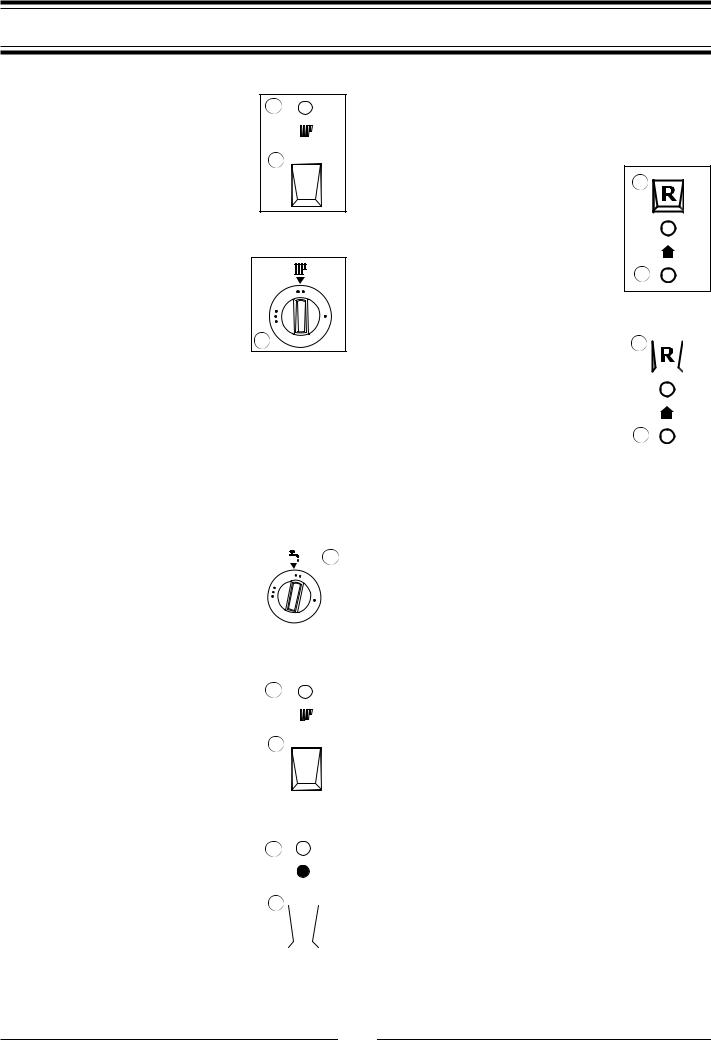
3. Boiler Shutdown Situations
Winter and Summer Operating Modes
In the ‘winter operating mode’, the boiler will |
|
|
produce both Central Heating and Domestic G |
||
Hot Water. In the ‘summer operating mode’, the |
|
|
boiler will produce only domestic hot water. |
|
|
Press button “F” to select winter mode. The |
F |
|
green LED “G” will illuminate. |
||
|
||
Adjusting the Heating
It is possible to set the temperature of the heating system by adjusting the knob “B” . By positioning the indicator somewhere between MIN and MAX, a temperature may
be obtained which varies from approximately
42˚C to about 82˚C.
B
External (Room) Thermostat Control
If an external (room) thermostat is installed, it is recommended that the temperature of the heating system be set by means of the knob “B” , leaving it at MAX position in order to obtain the best performance from the boiler and to allow the regulation of the external temperature to function efficiently.
Setting the Hot Water for Domestic Use
Both in the winter and summer mode, the temperature of the domestic hot water may be adjusted by rotating the knob “C” . A delivery temperature for the water may be
selected between approx. 36˚C to 54˚C, |
C |
depending on the flow rate of the water and |
|
the position of the knob between MIN and |
|
MAX settings. NOTE: Should the Domestic |
|
Hot Water not be hot enough, it may be |
|
necessary to slow the flow rate from the |
|
|
|
hot water outlet being used. |
|
Turning Off the Central Heating |
G |
|
To turn off the Central Heating, press the Central |
|
|
Heating button “F” ; the respective green LED “G” |
|
|
will go off. The boiler will stay in summer mode, |
F |
|
only providing Domestic Hot Water |
||
|
||
|
|
Turning Off the Boiler |
|
|
|
|
|
|
|
To turn the boiler off, press the button “A” ; the |
|
|
|
|
|
|
|
K |
|
|
|
|
|||
respective green LED “K” will go off. |
|
|
|
|
|||
|
|
|
|
|
|
|
|
|
A |
|
|
|
|
|
|
|
|
|
|
|
|
|
|
|
|
|
|
|
|
|
|
|
|
|
|
|
|
|
|
|
|
|
|
|
|
|
|
|
|
|
|
|
|
|
|
The boiler is equipped with safety devices that intervene in certain situations and shut it off. Most of these situations are communicated by means of the LED’s and at times the user may be able to remedy them.
Shutdown Due To Ignition Failure
In the event that the automatic ignition of the
burner has failed, the red LED. “I” will illumi- |
I |
|||
nate. In order to reset the ignition, the button |
|
|||
“J” must be pressed and released. Should the |
|
|||
boiler fail to ignite a second time, check that the |
|
|||
external gas cock is open. If the problem per- |
|
|||
sists, contact a |
local |
Service |
Agent. |
|
IMPORTANT!! Always |
wait 2 |
minutes |
before |
J |
resetting each time. |
|
|
|
|
|
|
|
|
|
Shutdown Due To Overheating
In the event that the safety limit is exceeded for |
|
|
|
|
|
|
|
|
|
|
|
||
the temperature of the water in the boilers |
I |
|
|
|
|
|
|
|
|
|
|||
exchanger, the thermostat shuts off the boiler |
|
|
|
|
|
|
and the red LED “I” illuminates. |
|
|
|
|
|
|
|
|
|
|
|
||
|
|
|
|
|
||
To remedy this situation, wait a few minutes to |
|
|
|
|
|
|
allow the exchanger to cool down, then press |
|
|
|
|
|
|
and release the reset button “J” . |
|
|
|
|
|
|
If this situation occurs frequently, contact a |
J |
|||||
local Service Agent. |
||||||
|
|
|
|
|
||
Temporary Shutdown Due To Defective Discharge of Exhaust Fumes
The boiler is fitted with safety devices, which in the event of a defective discharge of exhaust products, automatically interrupts the gas supply, thereby shutting off the boiler.
The shut-off of the boiler is temporary and is indicated by the illumination of the yellow L.E.D. “H” for a period of about 15 minutes. Once this time period has passed and the discharge state of exhaust system has returned to normal, the boiler automatically turns back on.
IMPORTANT!
If this situation occurs frequently, contact a local Service Agent so that they may check that the exhaust fumes are being expelled correctly, that the flue is installed correctly and that the area is ventilated properly.
4
3. Boiler Shutdown Situations |
4. Time clock |
|
|
|
|
Shutdown Due To Insufficient Circulation
If the boiler is off, one possible cause for this state is an insuffi- |
||
cient pressure of water in the system. |
D |
|
Check the system pressure on the pressure |
||
|
||
gauge “D” and if it is less than 0.5 bar, re- |
|
|
pressurise the system as instructed by your |
|
|
installer, should you be unsure some basic |
|
|
instructions are provided hereafter; |
|
|
Ensure that the filling loop hose is connected to the cold water inlet pipe and to either the Central Heating flow or return
Open the handle/s or tap/s to allow water into the Central Heating system
Once the needle on the pressure gauge reaches 1 Bar, close the handle/s or tap/s and disconnect the filling loop hose
Should it still be unclear how to proceed, please consult your installer.
If the boiler does not start up again, contact a local Service Agent. If there are frequent drops in pressure within the system, have a plumber check the heating system for possible water leaks.
Anti-frost Device
The boiler is fitted with a device which, in the event that the water temperature falls below 8˚C the pump activates and runs until a temperature of 18˚C is attained. In the event that the water temperature falls below 3˚C, the diverter valve switches to Domestic Hot Water and the burner fires and runs on minimum power until a temperature of 33˚C is attained.
This device is only activated when the boiler is operating perfectly and
-the system pressure is sufficient;
-the boiler is powered electrically;
-gas is being distributed.
UT011Ap
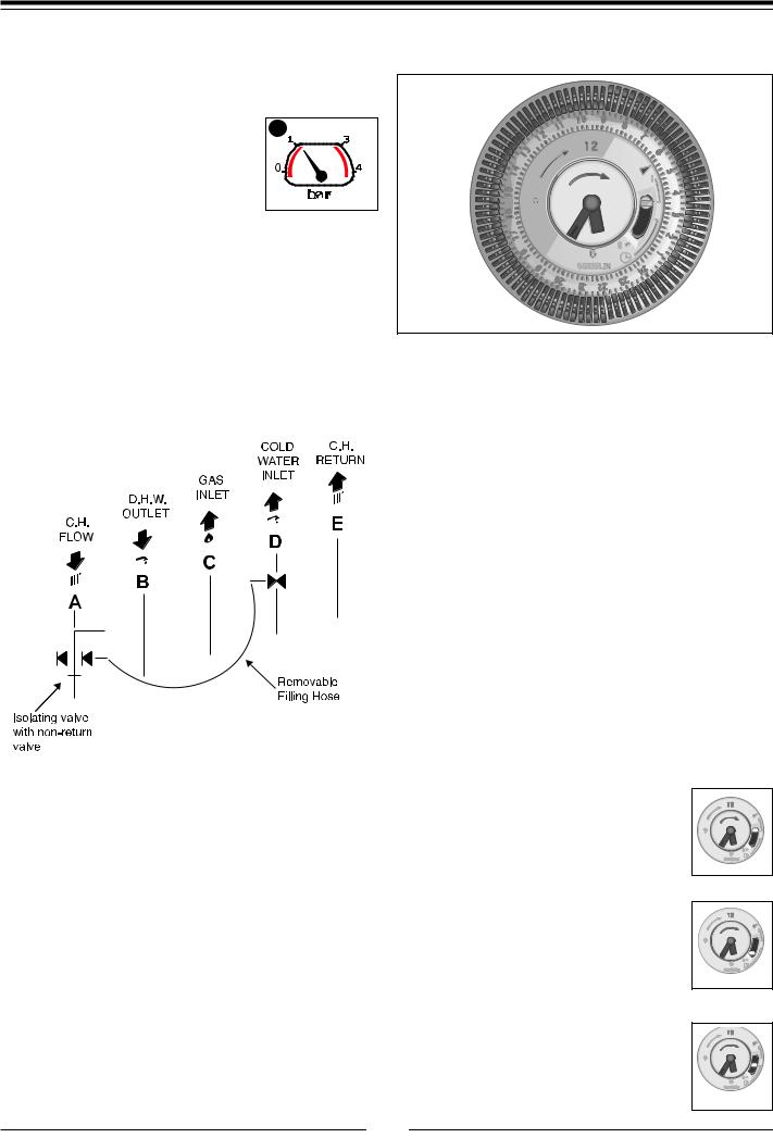
Note: the time clock is for central heating control only.
The time clock is provided with 96 switches, called riders, each of which covers a time interval of 15 minutes (four per hour). When a rider is switched from the inside (off setting) to the outside of the clock border (on setting), the circuit is closed (switch on) for a period of 15 minutes and then the boiler starts if the room thermostat (if installed) or the heating thermostat require heat (heating function on).
EXAMPLE
To set the heating of your home in the time interval from 7.00 am to 9.30 am and from 7.00 pm to 10.00 pm every day:
-rotate the outer ring of the clock in a clockwise direction until the correct time of day (24h) lines up with the arrow on the clock (at approx. 2 o’clock position);
-under no circumstances should the minute hand be moved manually;
-make sure all the switches, i.e. the riders, are placed on the inside of the clock border;
-pull outward the riders for 7.00 am and 9.30 am, and then all riders between these two;
-repeat this for 7.00 pm and 10.00 pm.
Other heating intervals may be set in the same way.
The timer has approximately 150 hours of battery back up for power failure.
The clock is provided with a selector switch with three positions (see figure):
1. Position “I” CONSTANT: in this position, the |
|
clock circuit is always closed (switch on), there- |
|
fore the boiler will constantly be on and will only |
|
shut off upon the request of the room thermo- |
|
stat (if installed) or the heating thermostat; |
UT014A |
|
2. Position “O” HEATING OFF: in this position, the clock circuit is always open (switch off) and the boiler will therefore never ignite for heating;
UT014A
3. “Central” Position PROGRAMMING ACTIVE: in this position, the programming set by the user is active.
UT014A
5

INSTALLATION AND SERVICING INSTRUCTIONS
5. GENERAL INFORMATION
5.1General Instructions
This manual is an integral and essential part of the product. It should be kept with the appliance so that it can be consulted by the user and our authorised personnel.
Please carefully read the instructions and notices about the unit contained in this manual, as they provide important information regarding the safe installation, use and maintenance of the product.
For operating instructions please consult the separate Previous User Guide.
Read the instructions and recommendations in these Installation Instructions carefully to ensure proper installation, use and maintenance of the appliance.
Keep this manual in a safe place.You may need it for your own reference while our Servicing Centre technicians or your installer may need to consult it in the future.
This is a combined appliance for the production of central heating (C.H.) and domestic hot water (D.H.W.).
This appliance must be used only for the purpose for which it is designed.
The manufacturer declines all liability for damage caused by improper or negligent use.
No asbestos or other hazardous materials have been used in the fabrication of this product.
Before connecting the appliance, check that the information shown on the data plate and the technical data section comply with the electric, water and gas mains of the property. You will find the data plate on the reverse of the control panel.
The gas with which this appliance operates is also shown on the label at the bottom of the boiler.
Do not install this appliance in a damp environment or close to equipment which spray water or other liquids.
Do not place objects on the appliance.
Do not allow children or inexperienced persons to use the appliance without supervision.
If you smell gas in the room, do not turn on light switches, use the telephone or any other object which might cause sparks. Open doors and windows immediately to ventilate the room. Shut the gas mains tap (at or adjacent to the gas meter) or the valve of the gas cylinder and call your Gas Supplier immediately. If you are going away for a long period of time, remember to shut the mains gas tap or the gas cylinder valve.
Always disconnect the appliance either by unplugging it from the mains or turning off the mains switch before cleaning the appliance or carrying out maintenance.
In the case of faults or failure, switch off the appliance and turn off the gas tap. Do not tamper with the appliance.
For repairs, call your local Authorised Servicing Centre and request the use of original spare parts. For in-guarantee repairs contact MTS (GB) Limited.
Check the following at least once a year:
1 - Check the seals for the water connections; replace any faulty seals.
2 - Check the gas seals; replace any faulty gas seals. 3 - Visual check of the entire unit.
4 - Visual check of the combustion process or analysis of combustion by-products (see section 3.6) and cleaning of the burner if needed.
5 - If called for by point. 3, dismantling and cleaning of the combustion
chamber.
6 - If called for by point. 4, dismantling and cleaning of the burner jets.
7 - Visual check of the primary heat exchanger:
-check for overheating in the blade assembly;
-clean the exhaust fan if needed.
8 - Adjustment of the flow rate of the gas: flow rate for lighting, partial load and full load.
9 - Check of the heating safety systems:
-safety device for maximum temperature (overheat thermostat);
-safety device for maximum pressure (safety valve). 10Check of the gas safety systems:
-safety device for lack of gas or flame ionisation (detection electrode);
-safety device for gas cock.
11Check of the electrical connection (make sure it complies with the instructions in the manual).
12Check of domestic hot water production efficiency (flow rate and temperature)
13General check of the combustion by-products of the discharge/ventilation system.
14Check of the general performance of the unit.
NOTE: THESE CHECKS ARE NOT EXHAUSTIVE, FURTHER HYDRAULIC,
MECHANICAL, ELECTRICAL AND OPERATIONAL CHECKS MAY BE
REQUIRED AS NECESSARY.
6
General Information
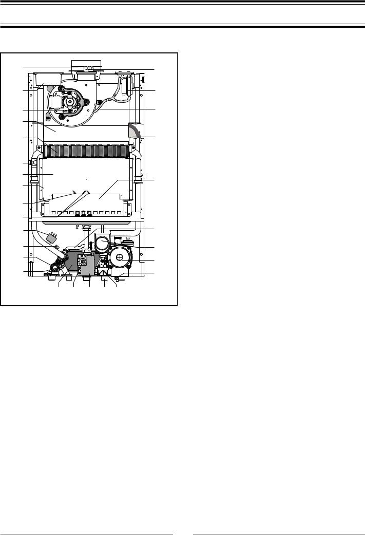
5.2Overall View
1 |
|
28 |
2 |
|
27 |
3 |
|
26 |
4 |
|
|
5 |
|
25 |
6 |
|
|
7 |
|
24 |
8 |
|
|
|
|
|
9 |
|
|
10 |
|
23 |
11 |
|
|
|
|
|
12 |
|
22 |
13 |
|
21 |
14 |
|
20 |
Fig. 5.0 |
15 16 17 |
18 19 |
|
|
Legend:
1.Flue connector
2.Air intake for twin pipe flue systems
3.Fan
4.Combustion chamber hood
5.Heat exchanger
6.Safety thermostat
7.Combustion chamber
8.Combustion chamber insulation panel
9.Detection electrode
10.Ignition electrodes
11.Pump pressure switch
12.Main circuit temperature probe
13.Safety valve (3 bar)
14.Domestic hot water temperature probe
15.Secondary exchanger
16.Gas valve
17.Spark generator
18.Domestic hot water inlet filter
19.D.H.W. flow switch
20.Drain valve
21.Circulation pump with automatic air release valve
22.Motorised diverter valve
23.Automatic By-pass
24.Burner
25.Expansion vessel
26.Air pressure switch tube
27.Air pressure switch
28.Combustion analysis points
7

6.INSTALLATION
6.1 Reference Standards |
6.2 Siting the Appliance |
The technical information and instructions provided herein below are intended for the installer / Servicing Technician so that the unit may be installed and serviced correctly and safely.
In the United Kingdom the installation and initial start up of the boiler must be by a CORGI Registered Installer in accordance with the installation standards currently in effect, as well as with any and all local health and safety standards i.e. CORGI.
In the Republic of Ireland the installation and initial start up of the appliance must be carried out by a Competent Person in accordance with the current edition of I.S.813 “Domestic Gas Installations”, the current Building Regulations, reference should also be made to the current ETCI rules for electrical installation.
This appliance must be installed by a competent installer in accordance with current Gas Safety (installation & use) Regulations.
The installation of this appliance must be in accordance with the relevant requirements of the Local Building Regulations, the current I.E.E. Wiring Regulations, the bylaws of the local water authority, in Scotland, in accordance with the Building Standards (Scotland) Regulation and Health and Safety document No. 635 “Electricity at work regulations 1989” and in the Republic of Ireland with the current edition of I.S. 813, the Local Building Regulations (IE).
C.O.S.H.H.
Materials used in the manufacture of this appliance are non-haz- ardous and no special precautions are required when servicing. Installation should also comply with the following British Standard Codes of Practice
BS 7593:1992 Treatment of water in domestic hot water central heating systems
BS 5546:1990 Installation of hot water supplies for domestic purposes
BS 5440-1:2000 Flues
BS 5440-2:2000 Air supply
BS 5449:1990 Forced circulation hot water systems BS 6798:1987 Installation of gas fired hot water boilers
of rated input not exceeding 60kW
BS 6891:1989 Installation of low pressure gas pipe up to 28mm
BS 7671:2001 IEE wiring regulations
BS 4814:1990 Specification for expansion vessels BS 5482:1994 Installation of L.P.G.
The appliance may be installed in any room or indoor area, although particular attention is drawn to the requirements of the current I.E.E. Wiring Regulations, and in Scotland, the electrical provisions of the Building Regulations applicable in Scotland, with respect to the installation of the combined appliance in a room containing a bath or shower, the location of the boiler in a room containing a bath or shower should only be considered if there is no alternative.
Where a room-sealed appliance is installed in a room containing a bath or shower the appliance and any electrical switch or appliance control, utilising mains electricity should be situated so that it cannot be touched by a person using the bath or shower, specifically in accordance with current IEE Wiring Regulations.
The location must permit adequate space for servicing and air circulation around the appliance as indicated in Section 6.4. The location must permit the provision of an adequate flue and termination.
For unusual locations special procedures may be necessary. BS 6798-1987 gives detailed guidance on this aspect.
A compartment used to enclose the appliance must be designed specifically for this purpose. No specific ventilation requirements are needed for the installation within a cupboard.
This appliance is not suitable for outdoor installation.
The type C appliances (in which the combustion circuit, air vent intake and combustion chamber are air-tight with respect to the room in which the appliance is installed) can be installed in any type of room.
Secondary ventilation is not required with this boiler. The boiler must be installed on a solid, non-combustible, permanent wall to prevent access from the rear.
8

Installation
6.3Overall Dimensions
FIG. 6.1 |
QT002A |
Legend: |
A = Central Heating Flow (3/4”)
B = Domestic Hot Water Outlet (1/2”)
C = Gas Inlet (3/4”)
D = Domestic Cold Water Inlet (1/2”)
E = Central Heating Return (3/4”)
6.4 |
Clearances |
|
FIG. 6.2 |
DM001B |
|
In order to allow access to the interior of the boiler for maintenance purposes, the boiler must be installed in compliance with the minimum clearances indicated in FIG. 6.2
6.5MOUNTING THE APPLIANCE
After removing the boiler from its packaging, remove the template from the separate box containing the connection kit.
Note: Pay particular attention to any test water that may spill from the appliance.
FIG. 6.3
Place the template in the position the appliance is to be mounted and after ensuring it is hanging squarely, use it to drill the holes for the hanging bracket and flue pipe(s) NB: For further information relating to the flue installation please refer to Section 6.9 Flue Connection. (If the appliance is to be fitted on a wall of combustible material, the wall must be protected by a sheet of fireproof material).
If the appliance is to be fitted into a timber framed building, guidance should be sought from the IGE document REF: IGE/UP/7.
9
Installation
6.5.1.Drill the wall and plug using those supplied with the connections kit, position the bracket and secure with the wall bolts supplied. Note: It is highly recommended that a spirit level be used to position the appliance to ensure that it is perfectly level.
6.5.2.Position the appliance on the hanging bracket and connect the isolating valves supplied in the connection kit as shown on the wall template (see also Sections 6.7 Gas Connections, 6.8 Water Connections & FIG. 6.3).
6.6Electrical Connection
For safety purposes, have a competent person carefully check the electrical system in the property, as the manufacturer will not be held liable for damage caused by the failure to earth the appliance properly or by anomalies in the supply of power. Make sure that the residential electrical system is adequate for the maximum power absorbed by the unit, which is indicated on the rating plate. In addition, check that the section of cabling is appropriate for the power absorbed by the boiler.
The boiler operates with alternating current, as indicated in the Technical Information table in Section 13, where the maximum absorbed power is also indicated. Make sure that the connections for the neutral and live wires correspond to the indications in the diagram. The appliance electrical connections are situated on the reverse of the control panel.
IMPORTANT!
In the event that the power supply cord must be changed, replace it with one with the same specifications.
Note: The diagrams for the electrical system are indicated in section 6.13.
Warning, this appliance must be earthed.
External wiring to the appliance must be carried out by a competent person and be in accordance with the current I.E.E. Regulations and applicable local regulations.
The appliance is supplied with a fly-lead already connected, this must be connected to a 240v supply fused at 3A and must facilitate complete electrical isolation of the appliance, by the use of a fused double pole isolator having a contact separation of at least 3 mm in all poles or alternatively, by means of a 3 A fused three pin plug and unswitched shuttered socket outlet both complying with BS 1363.
The point of connection to the Electricity supply must be readily accessible and adjacent to the appliance unless the appliance is installed in a bathroom when this must be sited outside the bathroom (see section 6.2).
Should external controls be required, the design of the external electrical circuits should be undertaken by a competent person, see section 6.12 for further information.
6.7Gas Connection
The local gas region contractor connects the gas meter to the service pipe.
If the gas supply for the boiler serves other appliances ensure that an adequate supply is available both to the boiler and the other appliances when they are in use at the same time.
Pipe work must be of an adequate size. Pipes of a smaller size than the boiler inlet connection should not be used.
6.8Water Connections
View of the Boiler Connections
F |
G |
Fig. 6.4
TE020E
Legend:
A= Central Heating Flow
B= Domestic Hot Water Outlet
C= Gas Inlet
D= Domestic Cold Water Inlet
E= Central Heating Return
F= Safety Valve Outlet
G= Drain Valve
Pipe Work:
Copper tubing to BS EN 1057:1996 is recommended for water pipes. Jointing should be either with capillary soldered or compression fittings.
Where possible pipes should have a gradient to ensure air is carried naturally to air release points and water flows naturally to drain taps.
The appliance has a built-in automatic air release valve, however it should be ensured as far as possible that the appliance heat exchanger is not a natural collecting point for air.
Except where providing useful heat, pipes should be insulated to prevent heat loss and avoid freezing.
Particular attention should be paid to pipes passing through ventilated spaces in roofs and under floors.
By-pass:
The appliance includes an automatic by-pass valve, which protects the main heat exchanger in case of reduced or interrupted water circulation through the heating system, due to the closing of thermostatic valves or radiators.
SYSTEM DESIGN:
This boiler is suitable for sealed systems only.
10
Installation
E
D
C
B
A
FIG. 6.5
Drain Cocks:
These must be located in accessible positions to permit the draining of the whole system and should be fitted at all low points. The taps must be at least 15mm nominal size and manufactured in accordance with BS 2870:1980.
Safety Valve Discharge:
The discharge should terminate facing downward on the exterior of the building in a position where discharging (possibly boiling water & steam) will not create danger or nuisance, but in an easily visible position, and not cause damage to electrical components and wiring.
The discharge must not be over an entrance or a window or any other type of public access.
Air Release Points:
These must be fitted at all high points where air naturally collects and must be sited to facilitate complete filling of the system. The appliance has an integral sealed expansion vessel to accommodate the increase of water volume when the system is heated. It can accept up to 6 litres (1.3 gal) of expansion water. If the heating circuit has an unusually high water content, calculate the total expansion and add an additional sealed expansion vessel with adequate capacity. This should be located on the return pipe work as close as possible to the pump inlet.
Mains Water Feed - Central Heating:
There must be no direct connection to the mains water supply even through a non-return valve, without the approval of the Local Water Authority, therefore a temporary method for initially filling the system and replacing lost water during servicing in accordance with current Water Regulations and bylaws must be provided (FIG. 6.6).
Note: The installer should ensure that there are no leaks as frequent filling of the heating system can lead to premature scaling of the main exchanger and failure of hydraulic components.
Domestic Water:
The domestic water must be in accordance with the relevant recommendation of BS 5546:1990. Copper tubing to BS EN 1057:1996 is recommended for water carrying pipe work and must be used for pipe work carrying drinking water, a scale reducer should also be used to reduce the risk of scale forming in the domestic side of the heat exchanger.
CENTRAL HEATING
Detailed recommendations are given in BS 6798:1987 and BS 5449-1:1990, the following notes are given for general guidance.
Residual Head of the Boiler T=20°C
VR003A |
FIG. 6.6
11
Installation
6.9Flue Connections
FLUE SYSTEM
The provision for satisfactory flue termination must be made in accordance with BS 5440-1.
The appliance must be installed so that the flue terminal is exposed to outside air.
The terminal must not discharge into another room or space such as an outhouse or lean-to.
It is important that the position of the terminal allows a free passage of air across it at all times.
The terminal should be located with due regard for the damage or discolouration that might occur on buildings in the vicinity and consideration must be given to adjacent boundaries.
In cold or humid weather water vapour may condense on leaving the flue terminal. The effect of such “pluming” must be considered.
If the terminal is less than 2 metres above a balcony, above ground or above a flat roof to which people have access, then a suitable terminal guard must be fitted. When ordering a terminal guard, quote the appliance model number.
A suitable terminal guard is available from:
TOWER FLUE COMPONENTS
Morley Road
Tonbridge
Kent TN9 1RA
The minimum acceptable spacing from the terminal to obstructions and ventilation openings are specified in FIG. 6.7.
FIG. 6.7 |
FU010ARev1 |
TERMINAL POSITION |
mm |
||
A |
- |
Directly below an openable window |
|
|
|
or other opening300 |
|
B |
- |
Below gutters, solid pipes or drain pipes |
75 |
C - |
Below eaves |
200 |
|
D - |
Below balconies or car-port roof |
200 |
|
E |
- |
From vertical drain pipes and soil pipes |
150 |
F |
- |
From internal or external corners |
300 |
G - |
Above ground or balcony level |
300 |
|
H |
- |
From a surface facing a terminal |
600 |
I |
- |
From a terminal facing a terminal |
1200 |
J |
- |
From an opening in the car port |
|
|
|
(e.g. door, window) into dwelling |
1200 |
K |
- |
Vertically from a terminal in the same wall |
1500 |
L |
- |
Horizontally from a terminal in the same wall |
300 |
M - |
Horizontally from an opening window |
300 |
|
N |
- |
Fixed by vertical flue terminal |
|
NOTE: THE FLUE MUST NOT TERMINATE IN A PLACE LIKELY TO CAUSE
NUISANCE
IMPORTANT!
For all flue systems, a restrictor may need to be inserted into the exhaust manifold, the size of the restrictor and details of fitting requirements are shown in Table 6.1 (Page 18).
Ø 60/100 mm |
FU003A |
FIG. 6.8 |
Fitting the Coaxial Flue (Horizontal)
(For Telscopic Instructions see page 13 and for Vertical Flue and Twin Pipe Instructions see page 14)
CONTENTS:
1X SILICONE O-RING (60mm)
1X ELBOW (90O)
2X WALL SEALS (INTERNAL & EXTERNAL)
1X ALUMINIUM FLUE PIPE INCLUDING TERMINAL (1 METRE - 60/100)
2X FLUE CLAMPS
8X SCREWS
2X SEALS
Once the boiler has been positioned on the wall, insert the elbow into the socket (FIG 6.8) and rotate to the required position. NOTE:
It is possible to rotate the elbow 360o on its vertical axis.
Using the flue clamps, seals and screws supplied (FIG 6.8) secure the elbow to the boiler.
The 1 metre horizontal flue kit (705958) supplied is suitable for an exact X dimension of 823mm, and the 750mm horizontal flue kit (705785) is suitable for an exact X dimension of 573mm.
Measure the distance from the face of the external wall to the
12
Installation
face of the flue elbow (X - FIG 6.8), add 22 mm to this measurement, you now have the total length of flue required (including the terminal), this figure must now be subtracted from 860mm, you now have the total amount to be cut from the plain end of the flue.
Cut the flue to the required length ensuring that the distance between the inner and the outer flue is maintained (FIG 6.10). e.g. X = 508mm + 22mm = 530mm
860 - 530 = 330mm (Length to be cut from the plain end of the flue).
Once cut to the required length, ensure that the flue is free from burrs and reassemble the flue. If fitting the flue from inside of the building attach the grey outer wall seal to the flue terminal and push through the flue through the hole, once the wall seal has passed through the hole, pull the flue back until the seal is flush with the wall. Alternatively, the flue can be installed from outside of the building, the grey outer seal being fitted last.
Fitting the Telescopic Flue Kit (Horizontal)
CONTENTS:
1X SILICONE O-RING (60mm)
1X ELBOW (90O)
2X WALL SEALS (INTERNAL & EXTERNAL)
1X ALUMINIUM FLUE PIPE INCLUDING TERMINAL (TELESCOPIC - 60/100)
2X FLUE CLAMPS
8X SCREWS
2X SEALS
The telscopic flue is suitable for use with an exact minimum X dimension of 270mm and an exact maximum X dimension 470mm.
IMPORTANT!!
Do not extend the telescopic flue to an X dimension of more than 470mm. If longer lengths are required use extension pieces as necessary. Under no circumstances must the flue be cut.
The wall must then be made good around the flue (ensuring a fall
of 1o is maintained away from the boiler to the flue terminal). Once made good, place the inner (white) wall seal over the flue and push up to the wall, secure the flue to the elbow by using the clamp supplied.
For each additional 90o elbow 1 metre must be removed from the total flue length (maximum 4 metres including the 1st elbow). For each additional 45o elbow 0.5 metre must be subtracted from the total flue length (FIG 6.13).
Fitting the Coaxial Flue (Vertical)
(For Twin Pipe Instructions see page 14)
CONTENTS:
1X SILICONE O-RING (60mm)
1X ELBOW (90O)
2X WALL SEALS (INTERNAL & EXTERNAL)
1X ALUMINIUM FLUE PIPE INCLUDING TERMINAL (TELESCOPIC - 60/100)
2X FLUE CLAMPS
8X SCREWS
2X SEALS
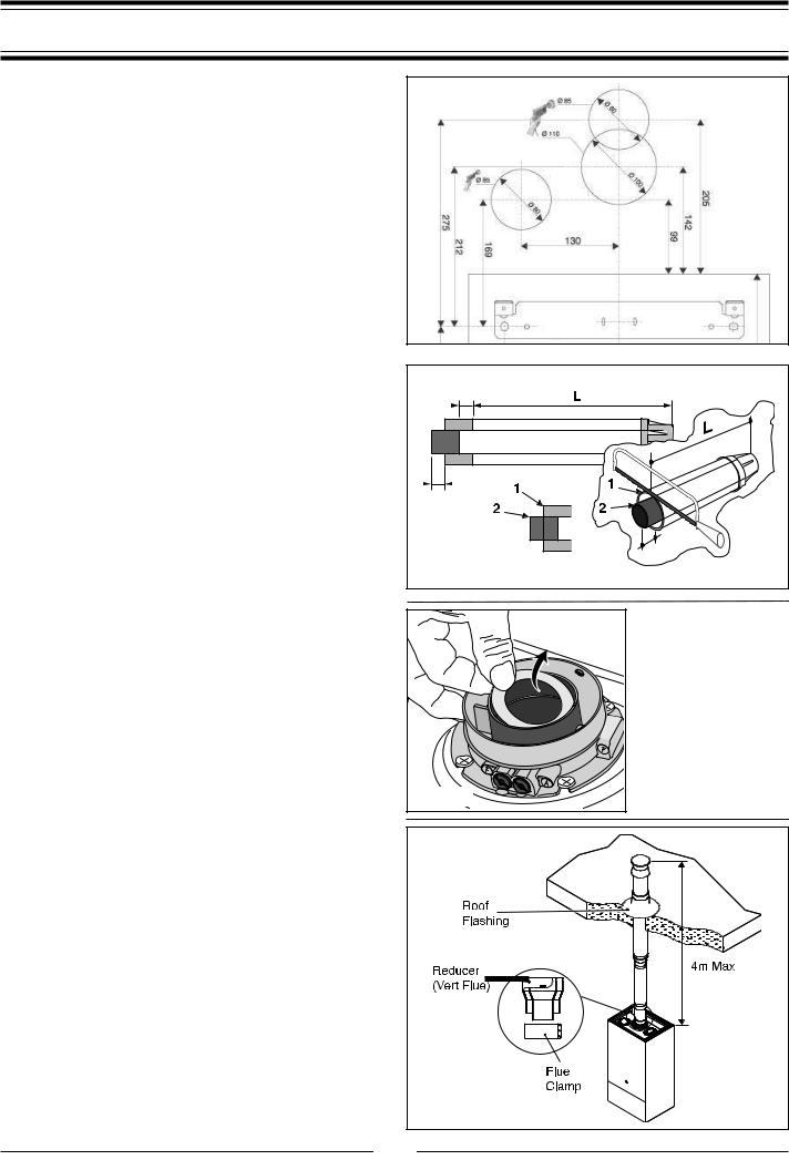
The vertical flue kit is supplied with a specially designed weather proof terminal fitted, it can be used either with a flat roof or a pitched roof. (see FIGS 6.12, 6.13).
FIG 6.9
25 mm |
|
|
25 mm |
|
|
25 |
mm |
|
FIG 6.10 |
||
|
FIG 6.11 |
WARNING
IT WILL BE NECESSARY
TO CONSULT TABLE 6.1 ON PAGE 18 TO
DETERMINE WHETHER THE FLUE RESTRICTOR IS REQUIRED. SHOULD IT NOT BE NEEDED, THE RESTRICTOR WILL NEED TO BE REMOVED
FROM THE FLUE GAS
COLLAR (FIG. 6.11).
FIG 6.12 |
13
Installation
The Vertical flue kits maximum and minimum useable lengths with both flat and pitched roof flashings are indicated in (Figs.
6.14 & 6.15).
Before proceeding to fit the flue, ensure that the maximum flue length has not been exceeded and that all elbows and bends have been taken into consideration, the maximum flue length is 4 metres, for each additional 90o elbow 1 metre must be subtracted from the total flue length, and for each 45o 0.5 metres must be subtracted from the total flue length (the offset and height of 2 x 45o can be seen in Fig. 6.16).
Mark the position of the flue hole in the ceiling and/or roof (see
FIG. 6.14 for distance from wall to the centre of the flue).
Cut a 110mm diameter hole through the ceiling and/or roof and fit the flashing plate to the roof.
Should it be necessary to cut the flue DO NOT cut the outer white ar inlet tube, cut the aluminium exhaust flue 6mm longer than the outer white air tube when used at minimum length. DO NOT cut more that 250mm from the inner aluminium exhaust flue.
To connect the vertical flue kit directly to the boiler, place the adaptor (see FIG 6.12) (supplied with vertical flue kit) onto the exhaust manifold and secure with the clamp, the vertical flue kit must then be inserted through the roof flashing, this will ensure that the correct clearance above the roof is provided as the terminal is a fixed height.
Should extensions be required, they are available in 1 metre
(Part No. 705786), 500mm (Part No. 705790) and 160mm lengths (Part No. 705812), they must be connected directly to the boiler and secured with the clamp supplied before connecting the adaptor to allow the vertical flue kit to be fitted. In the event that extension pieces need to be shortened, they must only be cut at the male end and it must be ensured that the distance between the inner and outer flue are kept (Fig. 6.10).
When utilising the vertical flue system, action must be taken to ensure that the flue is supported adequately to prevent the weight being transferred to the appliance flue connection.
When the flue passes through a ceiling or wooden floor, there must be an air gap of 25mm between any part of the flue system and any combustible material. The use of a ceiling plate will facilitate this. Also when the flue passes from one room to another a fire stop must be fitted to prevent the passage of smoke or fire, irrespective of the structural material through which the flue passes.
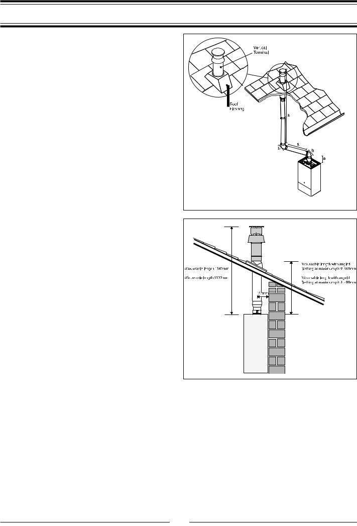
Fitting the Flue (Twin Pipe)
Where it is not possible to terminate the flue within the distance permitted for coaxial flues, the twin flue pipe can be used by fitting a special adaptor to the flue connector and using the aperture for the air intake located on top of the combustion chamber.
Considerations necessary for twin flue installation;
It is most important to avoid any possible condense formation entering the appliance.
FIG 6.13 |
NOTE: MAX LENGTH = a+a+a + |
b+b = a+a+a+0.5+0.5 |
COMBINED LENGTH NOT |
TO EXCEED 4m |
FIG 6.14 |
14

Installation
According to Table 6.1 (Page 18) decide if condensation will form within the flue. If yes, there are two options;
1)Where condense will form but can be negated with insulated flue, install the insulated flue with a fall of 5mm in every metre away from the boiler.
2)The exhaust flue will have a fall of 3o back to the boiler
and a suitable trap will be fitted on the exhaust as close to the boiler as possible, condense will then be suitably disposed of.
Where the flue runs through cold spots, i.e. loft areas, condense is likely to be formed, therefore a fall back to the boiler and a trap is required.
Always ensure that the flue is adequately supported, avoiding low points. (MTS supply suitable clamps as Part No. 705778).
To utilise the air intake it is necessary to:
Remove the ‘knockout’ of the air intake by cutting it with a suitable knife (FIG. 6.16).
Insert the elbow/flue pipe into the air intake until it stops.
The twin flue pipes can be fitted with or without additional elbows and need no clamps, simply ensure that the red o-ring is inserted in the female end of the flue pipe and push the extension piece fully into the previous section of flue pipe or elbow, check that the o-ring is not dislodged when assembling the flue.
Twin pipe can also be converted back to Coaxial flue to enable vertical termination with a coaxial kit by using the pipe bridge (Twin - Coaxial Adaptor - Part No. 705767). When running the twin flue pipe vertically, a condense trap must always be used on the exhaust pipe.
It is not recommended that the pipe bridge be used for horizontal termination, however in the unlikely event that this proves to be a necessity it is extremely important that the entire flue has a fall of 3o back to the boiler, is suitably trapped and where the 60mm inner flue of the concentric terminal connects to the pipe bridge, this point must be adequately sealed with silicone sealant to avoid condense leakage at this point.
Note: Vertical twin flue installations must have a trap on the exhaust. MTS supply a suitable condense trap with float Part No. 705774 and recommend that this be used in the event that the flue may not form condense.
When siting the twin flue pipe horizontally, the air intake and exhaust terminals must terminate on the same wall, the centres of the terminals must be a minimum of 280 mm apart and a maximum of 500mm, the air intake must not be sited above the exhaust terminal (refer to FIG. 6.19). The air intake pipe can be run horizontally, however, the terminal and the final 1 metre of flue must be installed with a fall away from the boiler to avoid rain ingress.
It is also strongly recommended that the air intake pipe run be constructed of insulated pipe to prevent condense forming on the outside of the tube.
The maximum permissible flue length for twin flue is dependent on the type of run used.
FIG 6.15
WARNING
IT WILL BE NECESSARY TO CONSULT TABLE 6.1 ON PAGE 18 TO DETERMINE WHETHER THE FLUE RESTRICTOR IS REQUIRED. SHOULD IT NOT BE NEEDED, THE RESTRICTOR
WILL NEED TO BE REMOVED FROM THE FLUE GAS COLLAR
(FIG. 6.11).
Minimum offset distance when using 2x 45o bends
FIG 6.16
15
 Loading...