

© 2003 aprilia s.p.a. - Noale (VE)
First edition: September 2003
Reprint:
Produced and printed by:
DECA s.r.l.
Via Risorgimento, 23/1 - Lugo (RA) - Italia
Tel. +39 - 0545 35235
Fax +39 - 0545 32844
E-mail: deca@decaweb.it
www.decaweb.it
SAFETY INFORMATION
The following conventions are used to
identify safety information throughout the
manual.
This symbol identifies safetyrelated information.
Whenever you see this symbol in the
manual or attached to the vehicle, use
utmost care to avoid the risk of injury.
Disregarding the instructions identified
by this symbol may put your safety, as
well as that of other persons or of the
vehicle at risk!
WARNING
Disregarding these indications may
lead to severe injury or death.
CAUTION
Disregarding these indications may
lead to minor injury or vehicle damage.
NOTE The term "Note" in this manual
precedes important information or
instructions.
TECHNICAL INFORMATION
Any operations preceded by this
+
symbol must be repeated on the
opposite side of the vehicle.
Unless expressly specified otherwise,
assembly is a reversal of the dismantling
procedure.
The terms "left" and "right" are referred to
the motorcycle when viewed from the
riding position.
WARNINGS - PRECAUTIONS GENERAL ADVICE
Before starting the engine, carefully read
this manual paying special attention to
section "SAFE RIDING".
Your safety and that of other road users
depends as much on your ability to
respond to other traffic and unexpected
events as on your familiarity with your
vehicle, the vehicle's efficiency and your
knowledge of basic "SAFE RIDING"
techniques. Becoming familiar with your
vehicle is the key to deal with traffic
effectively and safely.
On behalf of:
aprilia s.p.a.
via G. Galilei, 1 - 30033 Noale (VE) - Italy
Tel. +39 - (0)41 58 29 111
Fax +39 - (0)41 44 10 54
www.aprilia.com
use and maintenance Scarabeo 500 ABS
2
NOTE This manual forms an integral
part of the vehicle and must remain with
the vehicle, even if the vehicle is re-sold.
The information contained in this manual
was correct and up-to-date at the time of
going to print. However, minor
diskrepancies between manual
specifications and your vehicle are
possible as a result of aprilia's ongoing
efforts to improve product design. Please
refer to your aprilia Official Dealer for any
doubts about the information contained in
this manual.
For inspections and repairs not expressly
described in this manual, to purchase
aprilia genuine spare parts, accessories
and other products, or simply for technical
advice on specific matters, contact aprilia
Official Dealers and Service Centres only
for guaranteed prompt, quality service.
Thank you for choosing aprilia. Enjoy
your ride!
All rights to electronic storage,
reproduction and total or partial adaptation,
with any means, reserved in all Countries.
NOTE Emission and noise standards in
force in some countries require periodical
testing.
Owners who use their vehicles in these
countries must:
√ Have affected components replaced with
those having country-specific approval at
an aprilia Official Dealer and
√ Have the vehicle tested at the required
intervals.
NOTE After purchase, please report the
identification data indicated on the SPARE
PARTS IDENTIFICATION LABEL in the
table here below. The label is attached to
the left-hand frame member. Remove the
left inspection cover to give access to the
label, see page 57 (REMOVING THE
RIGHT AND LEFT INSPECTION
COVERS).
Identification data are:
√ YEAR = year of manufacture (Y,1,2,...);
√ I.M.= engineering change index (A,B,C,...);
√ COUNTRY CODES = country for which the
vehicle is approved (I,UK,A,...).
You will be asked to provide this
information when purchasing spare parts
or model-specific accessories from
aprilia Official Dealers.
Throughout the manual, the following
symbols are used to identify the different
versions:
Option
VERSION:
Italy Singapore
I
United
UK
Kingdom
Austria Israel
A
Portugal South Korea
P ROK
Finland Malaysia
SF
Belgium Chile
B
Germany Croatia
D
France Australia
Spain
E
Greece Brazil
GR
Holland
NL
Switzerland New Zealand
CH
Denmark Canada
DK
Japan
J
SGP
Slovenia
SLO
IL
MAL
RCH
HR
AUS
USA
United States
of America
BR
South Africa
RSA
NZ
CDN
use and maintenance Scarabeo 500 ABS
3

SUMMARY
SAFETY INFORMATION................................ 2
TECHNICAL INFORMATION ......................... 2
WARNINGS - PRECAUTIONS - GENERAL
ADVICE ......................................................... 2
SOMMARY ............................................................. 4
BASIC SAFETY RULES......................................... 6
CLOTHING ............................................................. 9
ACCESSORIES ................................................... 10
LOAD.................................................................... 10
ARRANGEMENT OF THE MAIN ELEMENTS12
ARRANGEMENT OF THE CONTROLS /
INSTRUMENTS ........................................... 14
INSTRUMENTS AND INDICATORS............. 14
INSTRUMENTS AND INDICATORS TABLEI ...... 15
KEY CONTROLS ......................................... 17
CONTROLS ON THE LEFT SIDE OF THE
HANDLEBAR ....................................................... 17
CONTROLS ON THE RIGHT SIDE OF THE
HANDLEBAR ....................................................... 18
IGNITION SWITCH .............................................. 19
STEERING LOCK ................................................ 19
ACCESSORIES ............................................ 20
DIGITAL CLOCK/DATE DISPLAY ....................... 20
MULTIFUNCTION DISPLAY................................ 21
DIGITAL ODOMETER .......................................... 22
RESETTING TRIP 1 AND TRIP 2 ........................ 23
TOOL KIT ............................................................. 23
UNLOCKING/LOCKING THE SADDLE ............... 23
GLOVE COMPARTMENT .................................... 24
SMALL STORAGE COMPARTMENT .................. 24
REAR TOP BOX .................................................. 24
MAIN COMPONENTS .................................. 25
FUEL .................................................................... 25
LUBRICANTS....................................................... 26
BRAKE FLUID - RECOMMENDATIONS ............. 27
DISK BRAKES ..................................................... 27
CHECKING BRAKE FLUID LEVEL...................... 28
COOLANT ............................................................ 29
CHECKING AND TOPPING UP........................... 30
TYRES ................................................................. 31
MUFFLER/EXHAUST SILENCER ....................... 32
INSTRUCTIONS FOR USE .......................... 33
PRE-RIDE CHECKS CHART ............................... 33
STARTING ........................................................... 34
MOVING OFF - RIDING ....................................... 36
RUNNING-IN ........................................................ 38
STOPPING ........................................................... 38
PLACING THE VEHICLE ON THE STAND ......... 39
SUGGESTIONS TO AVOID THEFT .................... 40
MAINTENANCE........................................... 41
PRE-RIDE CHECKS CHART ............................... 42
IDENTIFICATION DATA ...................................... 44
REAR TOP BOX................................................... 45
CHECKING AND TOPPING UP OIL LEVEL ........ 46
CHANGING ENGINE OIL AND THE ENGINE OIL
FILTER ................................................................. 47
CHECKING AND TOPPING UP TRANSMISSION
OIL LEVEL............................................................ 48
CHANGING TRANSMISSION OIL ....................... 49
AIR CLEANER...................................................... 49
CHECKING THE BRAKE PADS FOR WEAR ...... 50
CHECKING THE STAND ..................................... 52
CHECKING THE SWITCHES .............................. 52
CHECKING THE FRONT AND REAR
SUSPENSION ...................................................... 52
REAR SUSPENSION SPRING PRELOAD
ADJUSTMENT ..................................................... 53
CHECKING THE STEERING ............................... 53
STEERING DAMPER ........................................... 54
CHECKING ENGINE PIVOT SHAFT ................... 54
REMOVING THE RIGHT AND LEFT INSPECTION
COVERS .............................................................. 55
REMOVING THE WINDSHIELD .......................... 55
REMOVING THE REAR-VIEW MIRRORS .......... 56
REMOVING THE FRONT COVER ....................... 56
THROTTLE TWISTGRIP ADJUSTMENT ............ 57
SPARK PLUG....................................................... 58
BATTERY ............................................................. 59
LONG INACTIVITY OF THE BATTERY ............... 59
REMOVING THE BATTERY COVER .................. 60
CHECKING AND CLEANING THE BATTERY LEAD
CONNECTIONS AND TERMINALS ..................... 60
REMOVING THE BATTERY ................................ 60
CHECKING BATTERY FLUID LEVEL ................. 61
CHARGING THE BATTERY ................................ 61
INSTALLING THE BATTERY ............................... 61
REPLACING THE FUSES.................................... 62
ARRANGEMENT OF AUXILIARY FUSES
(FRONT COVER) ................................................. 62
ARRANGEMENT OF MAIN FUSES (BATTERY
COMPARTMENT) ................................................ 63
VERTICAL ADJUSTMENT OF THE
HEADLIGHT BEAM.............................................. 63
HORIZONTAL ADJUSTMENT OF THE
HEADLIGHT BEAM .............................................64
BULBS .................................................................. 64
REPLACING THE BULBS OF THE FRONT
DIRECTION INDICATORS ................................... 64
REPLACING THE HEADLIGHT BULBS .............. 65
LOW BEAM BULBS.............................................. 65
HIGH BEAM BULBS ............................................. 65
PARKING LIGHT BULBS ..................................... 66
REPLACING THE TAIL LIGHT BULBS................ 66
REPLACING THE REAR DIRECTION
INDICATOR BULBS ............................................. 67
REPLACING THE NUMBER PLATE BULB .........67
TRANSPORT............................................... 68
DRAINING THE FUEL TANK ............................... 68
CLEANING .................................................. 69
LONG INACTIVITY ............................................... 70
TECHNICAL DATA...................................... 71
LUBRICANT CHART ............................................ 75
OFFICIAL DEALERS AND SERVICE
CENTRES............................................................. 76
DISTRIBUTORS ................................................... 78
WIRING DIAGRAM - SCARABEO 500 ABS ........ 80
WIRING DIAGRAM KEY -
SCARABEO 500 ABS........................................... 81
uso e manutenzione Scarabeo 500 ABS
4

safe riding

BASIC SAFETY RULES
To ride a motorcycle, you must satisfy
certain legal requirements (driving licence,
minimum age, health conditions and
fitness, insurance cover, state taxes,
vehicle registration, number plate, etc.).
Practice riding in areas away from traffic or
on private ground until you become familiar
with the vehicle and its controls.
use and maintenance Scarabeo 500 ABS
6
Alcohol, drugs, psychotropic substances
and some medicines may affect your riding
leading to an accident.
Do not ride when you feel unwell,
distracted, tired or drowsy.
Most road accidents are caused by
inexperienced riders.
NEVER lend the vehicle to beginners or
anyone unless you are sure they meet the
necessary requirements.

Observe all road signs as well as national
and local road regulations.
Avoid sudden manoeuvres that put your
safety and that of other persons at risk (for
example: rearing up on the back wheel,
speeding, etc.). Adjust your speed and
riding to road surface conditions, visibility,
etc.
Avoid obstacles that could damage the
vehicle or make you lose control.
Avoid riding in the slip stream of preceding
vehicles in order to increase your speed.
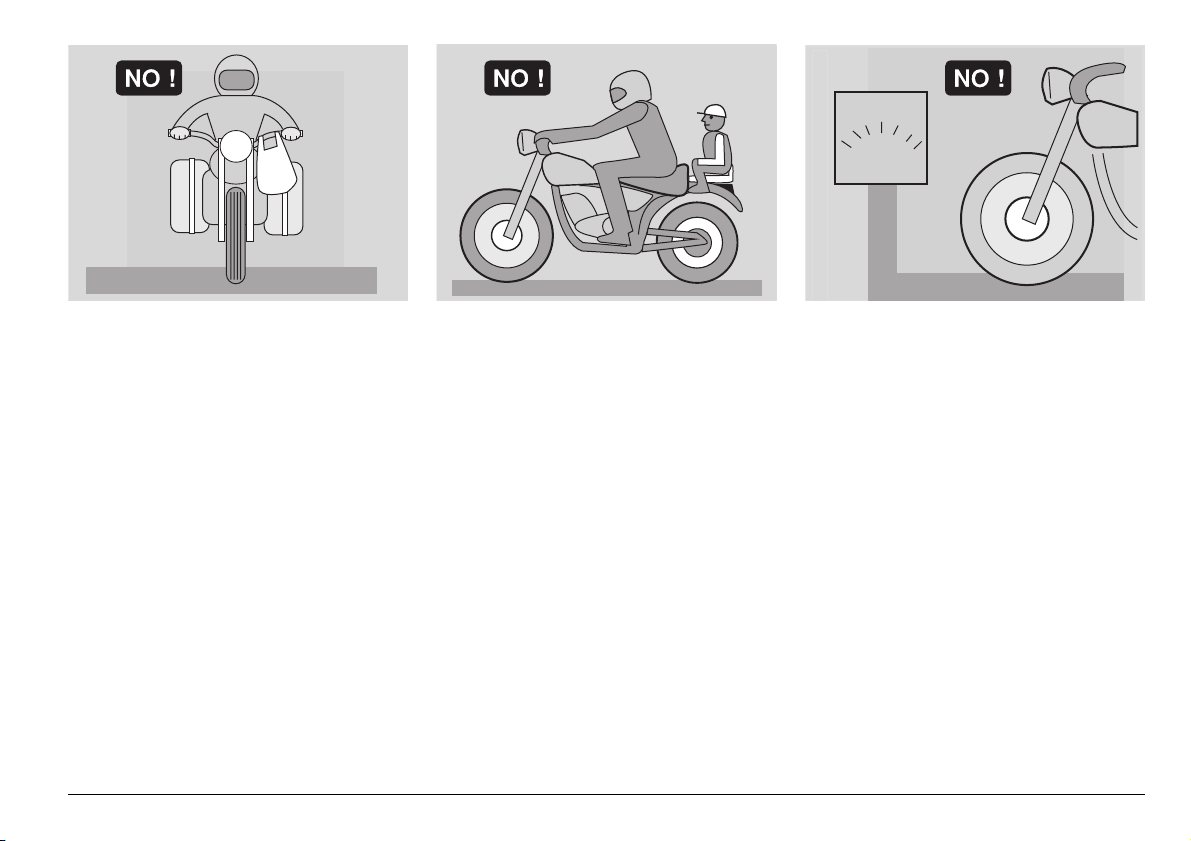
WARNING
Always keep both hands on the
handlebars and both feet on the footrest
platform (or on the rider footrests), in
the correct posture.
Do not stand up or stretch your limbs
while riding.
use and maintenance Scarabeo 500 ABS
7
OIL
COOLER
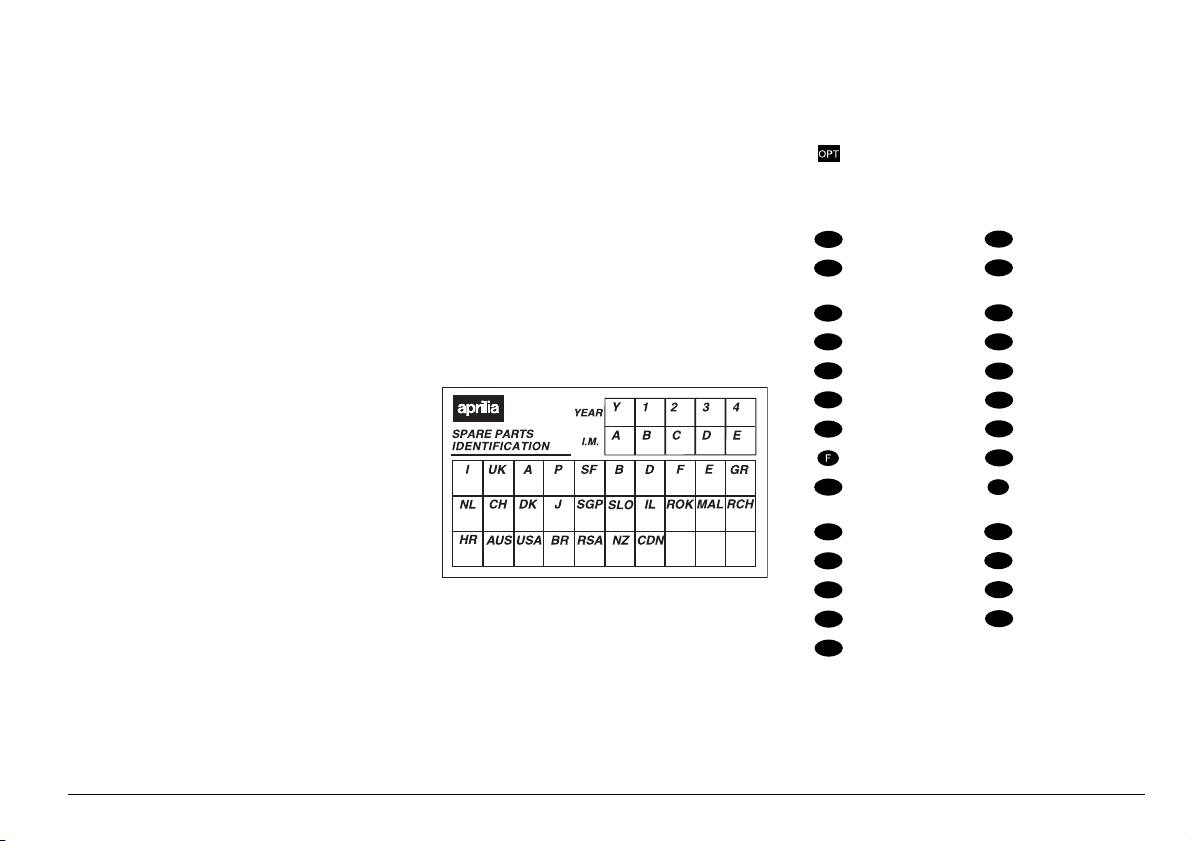
Keep your eyes on the road and pay close
attention to other traffic. Do not smoke, eat,
drink or read while riding.
use and maintenance Scarabeo 500 ABS
8
Use only the recommended fuels and
lubricants specified in the "LUBRICANT
CHART". Make it a rule to check oil, fuel
and coolant levels frequently.
If the vehicle has been involved in an
accident or has fallen over, check the
control levers, pipes, wires, braking
systems and critical parts for damage.
If necessary, have the vehicle inspected by
an aprilia Official Dealer. Special
attention should be paid to frame,
handlebars, suspension, safety parts and
all the devices that you are not able to
inspect yourself.
Report any malfunction to help mechanics
in their work.
Never use the vehicle when the amount of
damage makes it unsafe to ride.
A12
345
ONLY ORIGINALS
Do not change the position, inclination or
colour of: number plate, direction
indicators, lights and horns.
Any such changes to the vehicle will
invalidate the guarantee.
Making changes to the vehicle and/or
removing original components can
compromise vehicle performance and
safety or make it illegal to ride.
Observe all law regulations and national
and local regulations applicable to vehicle
equipment.
In particular, avoid any changes apt to
upgrade vehicle performance or alter its
original specifications.
Racing on public roads is prohibited by the
law.
Do not ride off the road.
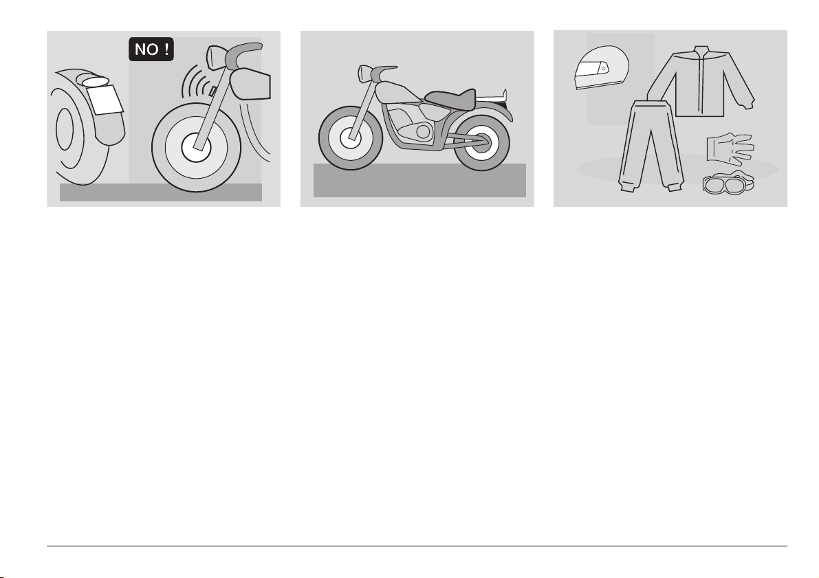
CLOTHING
Always wear an approved safety helmet
and fasten it securely. The helmet must not
be damaged, must fit correctly and the
visor must be clean.
Wear protective clothing. To ensure you
are easily seen, choose bright colours.
Clothing with reflective strips is also very
effective.
Protective clothing protects you in the
event of a fall and helps other road users to
see you, reducing the risk of an accident.
Wear close-fitting clothing, fastened at the
wrists and ankles.
Loose clothing or items, such as strings,
belts or neckties may impair your
movements while riding or become tangled
in the wheels or other moving parts.
use and maintenance Scarabeo 500 ABS
9
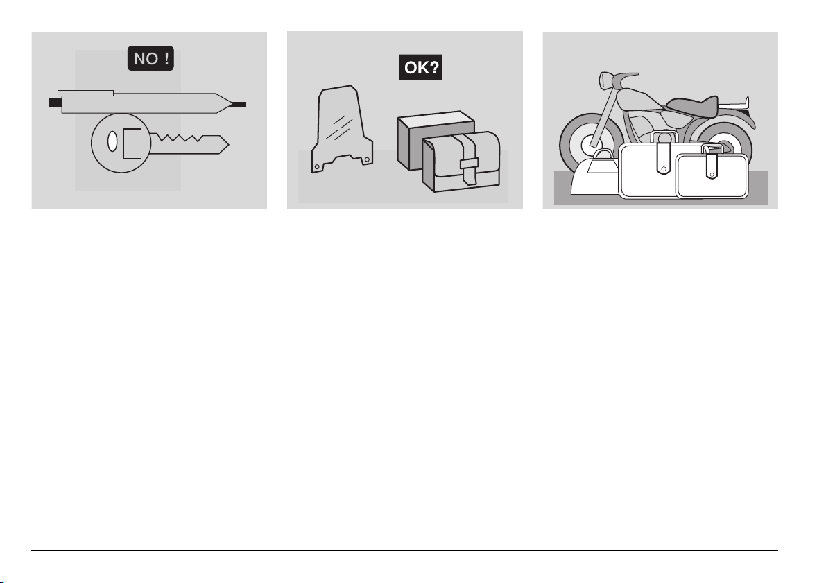
Do not keep any pointed or sharp objects,
such as keys, pens, glass items, etc. in
your pockets. They might cause injury in
the event of a fall. Do not allow your
passenger to keep such objects.
use and maintenance Scarabeo 500 ABS
10
ACCESSORIES
The owner of the vehicle is responsible for
the choice, installation and use of any
accessory.
Ensure that any accessory you install does
not cover the horn or the lights or impair
their operation, be in the way of
suspension travel or steering angle, impair
the operation of the vehicle controls,
reduce ground clearance or lean-in angle.
Do not install accessories that hinder
access to the vehicle controls, lengthening
your response time in an emergency.
Large fairings and windshields affect
vehicle aerodynamics and stability,
especially at high speed.
After installing any accessory, make sure it
is firmly secured to the vehicle and does not
create a hazard when riding. Do not add
any electrical devices or modify those fitted
to your vehicle. Overloading might kill the
engine unexpectedly while riding or a power
shortage might render the horn and lights
inoperative.
Use only genuine aprilia accessories.
LOAD
Be careful when loading your luggage.
Place your luggage as close as possible to
the centre of gravity of the vehicle and
ensure the load is distributed evenly to
avoid imbalance. Make sure the load is
firmly secured to the vehicle, especially
during a long trip.
KG!
Do not hang bulky, heavy and/or
dangerous objects on the handlebars,
mudguards and forks. This might slow
down steering response and adversely
affect handling.
Do not secure bulky luggage to the sides of
the vehicle, which could hit persons or
object while riding and make you lose
control of the vehicle.
Do not carry luggage unless it is firmly
secured to the vehicle.
Luggage should not protrude exceedingly
over the luggage rack or cover the lights,
horn or indicators.
Do not carry pets or children on the glove
compartment or on the luggage rack.
Do not exceed the maximum load allowed.
Excess load will make the vehicle unstable
and affect steering.
use and maintenance Scarabeo 500 ABS
11
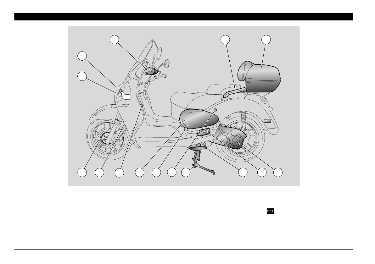
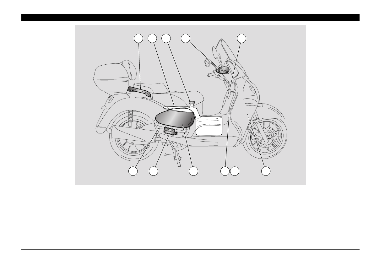
ARRANGEMENT OF THE MAIN ELEMENTS
2
1
KEY
1) Expansion tank
2) Coolant expansion tank plug
3) Rear brake fluid reservoir
4) Air cleaner
5) Rear top box
6) Converter air filter cover
7) Passenger left footrest
3 5
13
10
121411
10
9
4
8) Side stand
9) Centre stand
10) Headset √ intercom outlet ( )
11) Spark plug
12) Left inspection cover
13) Horn
14) Phonic wheel + speed sensor
8 7
6
use and maintenance Scarabeo 500 ABS
12
1 2 3 4
KEY
1) Passenger grab rail
2) Fuel tank
3) Fuel tank filler cap
4) Front brake fluid reservoir
5) Ignition switch / steering lock / saddle lock / rear top box lock
6) Auxiliary fuse carrier
7) Main fuse carrier
8) Battery
5
67891011
9) Right inspection cover
10) Passenger right footrest
11) Engine oil level / filler plug
use and maintenance Scarabeo 500 ABS
13
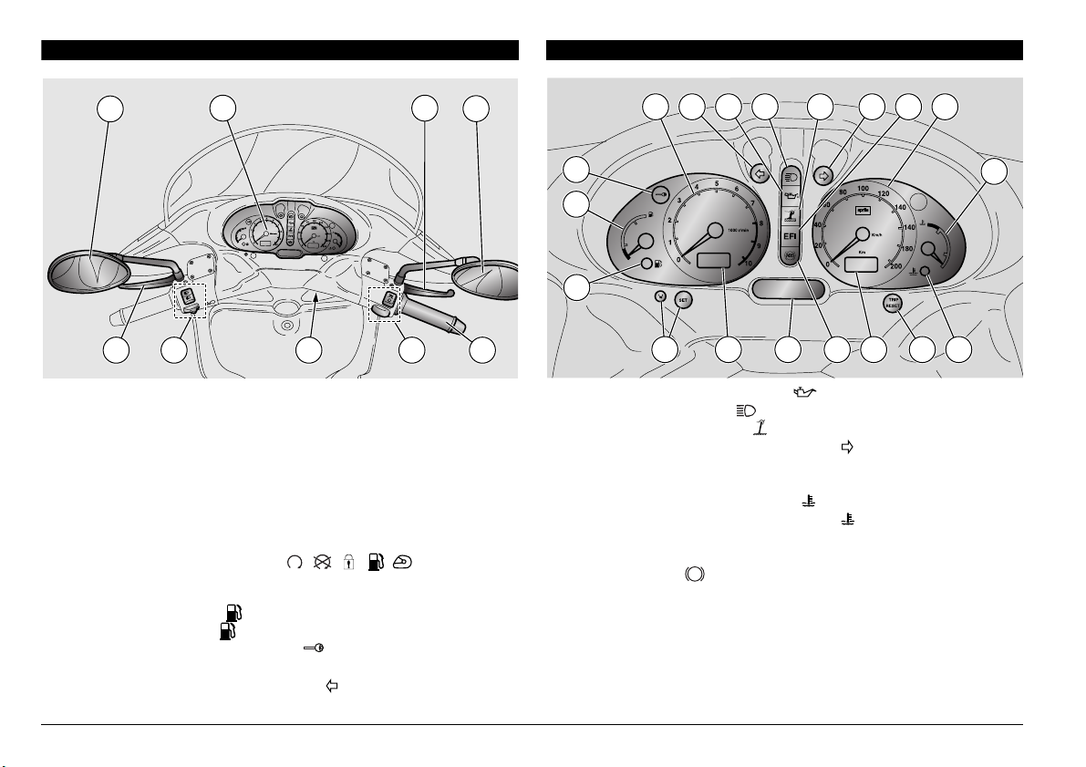
ARRANGEMENT OF THE CONTROLS / INSTRUMENTS
13141516171819
1
11
12
10987654
3
2
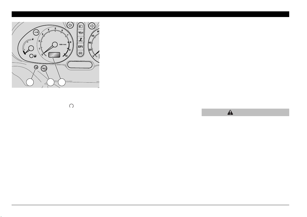
INSTRUMENTS AND INDICATORS
3
4 5
92 781
0
ARRANGEMENT OF THE CONTROLS / INSTRUMENTS - KEY
1) Electric controls on the left side of the handlebar
2) Integral braking lever (operates front and rear brakes)
3) Left rear-view mirror
4) Instruments and indicators
5) Front brake lever
6) Right rear-view mirror
7) Throttle twistgrip
8) Electric controls on the right side of the handlebar
9)Ignition switch /steering lock (----)
INSTRUMENTS AND INDICATORS - KEY
1) Amber low fuel light ( )
2) Fuel level indicator ( )
3) Red anti-theft (IMMOBILIZER) ( ) light
4) Rev counter
5) Green left direction indicator light ( )
6
6) Red engine oil pressure light ( )
7) Blue high beam light ( )
8) Amber side stand light ( )
9) Green right direction indicator light ( )
10) "EFI" warning light
11) Speedometer
12) Coolant temperature indicator( )
13) Red high coolant temperature light ( )
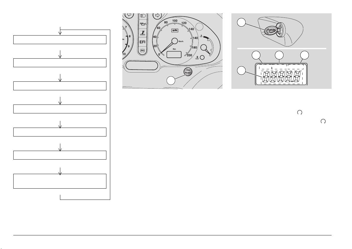
14) Display mode select (15) and reset (17 and 15)
15) Digital odometer
16) Red ABS light( ) amber
ABS
17) LCD
18) Digital clock
19) Digital clock mode select and reset buttons
use and maintenance Scarabeo 500 ABS
14
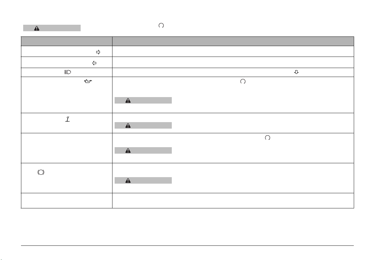
INSTRUMENTS AND INDICATORS TABLE
CAUTION
When the key is turned to ON “ ”, all warning lights, the dashboard lights and the segments of the three displays
come on for an instrumentation check-up and go out after three seconds.
Description Function
Right indicator repeater light ()
Left indicator repeater light
High beam light
Engine oil pressure light
Side stand light
EFI (Electronic Fuel Injection) light Comes on for about three seconds when the ignition switch is set to ≈∆ with the engine stopped. Provides a
ABS (Anti-Lock Braking System)
ABS
light
()
Anti-theft device (immobilizer) light (where fitted). Blinks when the engine is off as a deterrent to prevent theft.
() Comes on when the high beam is on or when you flash the high beam (PASSING ).
()
()
() Comes on briefly each time the ignition switch is set to ≈∆ with the engine stopped. Doubles as LED test
Blinks when the right direction indicator is on.
Blinks when the left direction indicator is on.
light.
The light must go out as soon as engine is fired.
CAUTION
contact an aprilia Official Dealer.
Comes on when the side stand is down.
CAUTION
fuel injection system test. The light must go out when the engine has started.
CAUTION
contact an aprilia Official Dealer.
It tests the anti-lock system. It stays on after the engine has started but it turns off after reaching a riding speed
over 5 km/h. It turns on in case of troubles.
CAUTION
aprilia Official Dealer and remember to ride with utmost care avoiding sudden braking.
Indicates that the anti-theft system is operating.
If the light comes on during normal engine operation, it means that engine
oil pressure in the circuit is too low. Stop the engine immediately and
When the side stand is down, the warning light comes on and engine
starting is inhibited.
If the EFI light comes on during normal engine operation, it means that there is a
fault in the electronic fuel injection system. Stop the engine immediately and
If the light comes on during normal engine operation, it means that there is a
failure in the anti-lock braking system. Should this happen, please call an
use and maintenance Scarabeo 500 ABS
15
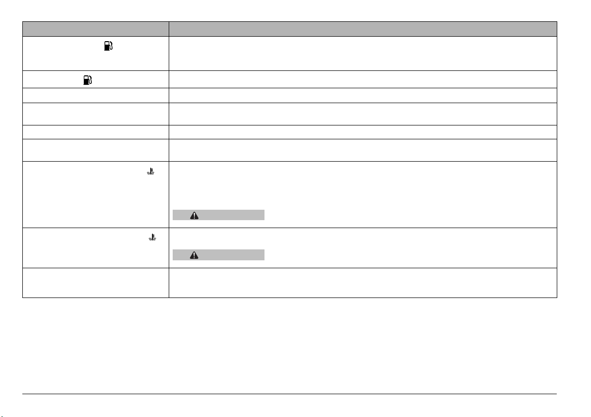
Description Function
Fuel level indicator ( )
Low fuel light ( )
Rev counter Gives engine rpm.
Digital clock The display can be toggled between hour and date indication, see page 20 (DIGITAL CLOCK/DATE
Speedometer Gives road speed
Digital odometer Gives total distance covered in kilometres and double trip meter (TRIP1, TRIP 2), see page 23 (RESETTING
Coolant temperature indicator ( )
High coolant temperature light ( )
Multifunction Liquid Crystal Display The display shows: external temperature, average and maximum speed, battery voltage, average
Indicates approximate fuel level in the tank.
When the pointer reaches the red area, it means that the quantity of fuel left in the tank is about 2 litres.
Refuel as soon as possible, see page 27 (FUEL).
Comes on when there are about 2 litres of fuel left in the tank.
DISPLAY).
TRIP 1 AND TRIP 2) for trip meter operation
Indicates the approximate temperature of coolant in the engine. When the pointer begins to move away from
the "Min" level, the engine is warm enough to ride.
The central portion of the scaled area corresponds to normal running temperature range. If the pointer goes
into the red zone or the warning light comes on, stop the engine and check coolant level, see page 31
(COOLANT).
CAUTION
Comes on when the coolant temperature pointer reaches the red area. Immediately stop the engine and check
coolant level, see page 31 (COOLANT).
CAUTION
consumption since last RESET, lap timer and kilometres to go until next service; see page 21
(MULTIFUNCTION LIQUID CRYSTAL DISPLAY).
Exceeding the maximum temperature allowed (red "Max" zone of the scaled
area) may lead to severe engine damage.
If the maximum temperature allowed is exceeded for a long period, the
engine may be seriously damaged.
use and maintenance Scarabeo 500 ABS
16
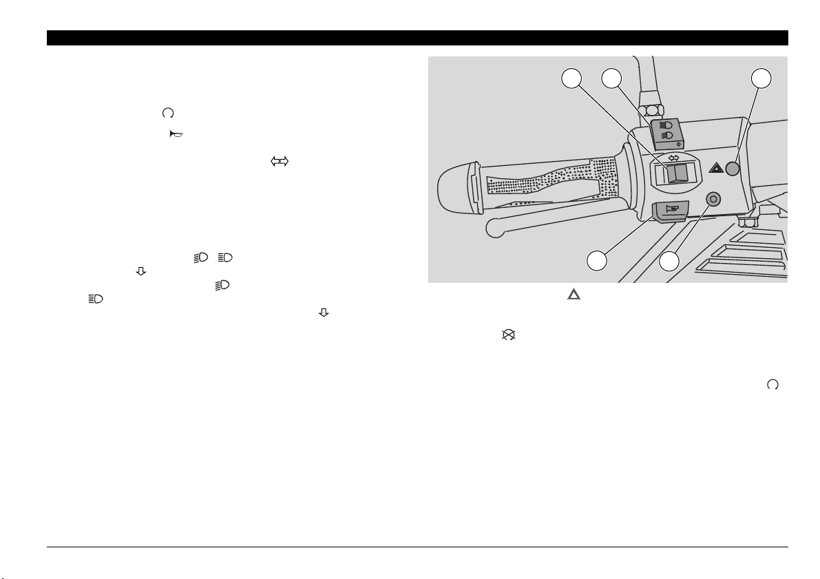
KEY CONTROLS
CONTROLS ON THE LEFT SIDE OF THE HANDLEBAR
NOTE The electric components work only when the ignition
switch is in position
1) HORN BUTTON ( )
Press it to operate the horn.
2) DIRECTION INDICATOR SWITCH ( )
Move the switch to the left in order to signal your intention to
turn left; move the switch to the right to signal a right turn.
Press the switch at the centre to cancel the signal.
The indicators reset automatically after 40 seconds or after the
vehicle has covered 500 m. The automatic reset system only
operates when the vehicle is in motion.
3) DIMMER SWITCH ( - ) / HIGH BEAM FLASHER
(PASSING )
Set the dimmer switch to
≈∆ to turn on the high beam.
to
Push the dimmer switch to position (PASSING ) to flash the
high beam.
≈∆.
≈∆, to turn on the low beam, set it
NOTE Release the switch to stop the flasher.
4) MODE BUTTON (MODE)
Press it repeatedly to select the various indications provided
by the multifunction display.
2 3 5
PASSING
MODE
1
4
5) HAZARD BUTTON ( )
OPERATION Press the button to activate the emergency stop
blinker. When the blinker is on, it is possible to turn the ignition
switch to and extract the key.
DEACTIVATION
Insert the key into the ignition switch and turn it to position ≈∆,
press the HAZARD button again to turn off the blinker.
use and maintenance Scarabeo 500 ABS
17
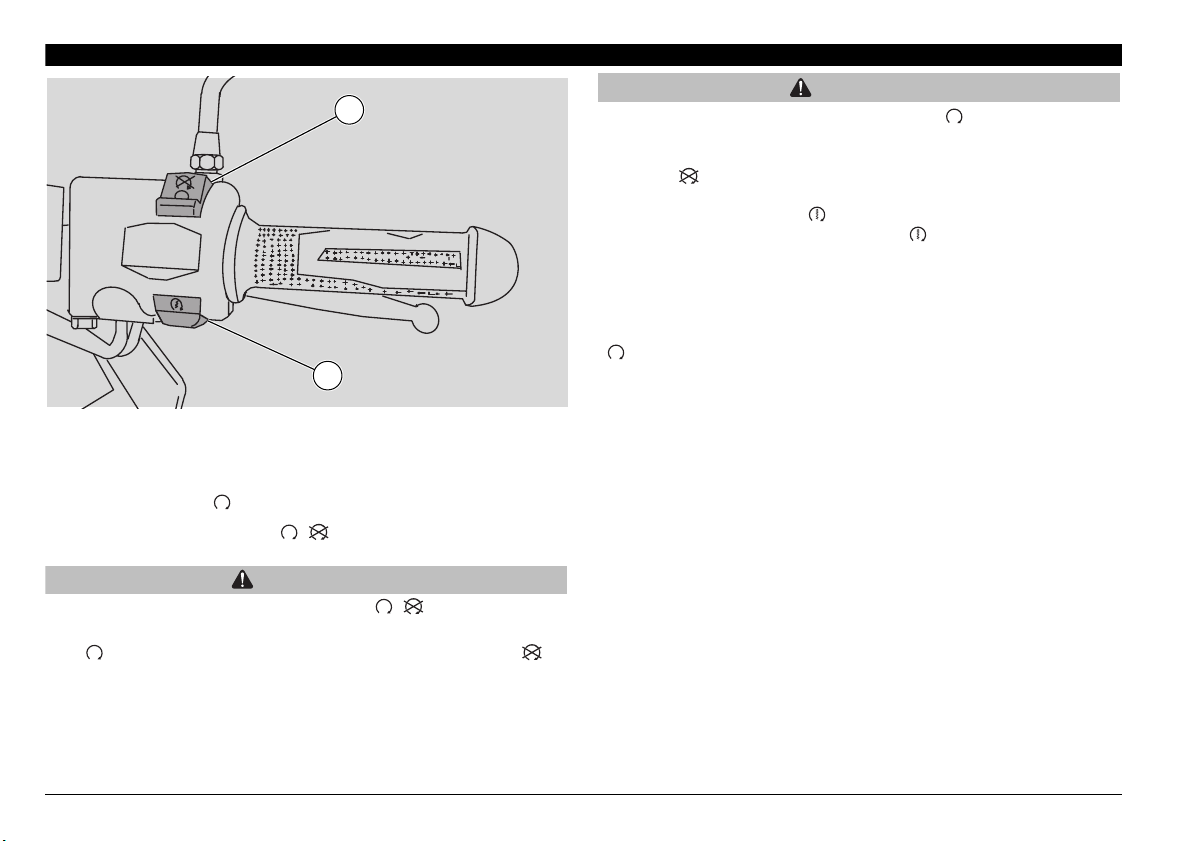
1
2
CONTROLS ON THE RIGHT SIDE OF THE HANDLEBAR
NOTE The electric components work only when the ignition
switch is in position ≈∆.
1) ENGINE KILL SWITCH ( - )
WARNING
Do not operate the engine kill switch “ - ” while riding.
This is a safety or emergency switch. When it is in position
≈∆, the engine can be started. When set to position ≈∆, it
will stop the engine.
CAUTION
Leaving the ignition switch in position “ ” when the engine
is stopped may flatten the battery. After stopping the vehicle,
stop the engine and then turn the ignition switch to
position“ ”.
2) STARTER BUTTON ( )
When pressed, the starter button ≈≈, turns the engine over.
See page 36 (STARTING) for starting procedure.
Deactivation
When the key is inserted into the ignition switch and turned to
≈∆, the device is automatically disconnected.
use and maintenance Scarabeo 500 ABS
18

1
IGNITION SWITCH
The ignition switch (1) is positioned on the
right side, near the steering tube.
NOTE The key (2) operates the ignition
switch /steering lock, the saddle lock and
the glove compartment flap.
Two keys are delivered along with the vehicle (one spare key).
NOTE Do not keep the spare key on the
vehicle.
I
D
A
Z
PUSH
2
STEERING LOCK
WARNING
Never turn the key to position “ ”
while riding or you might lose control of
the vehicle.
OPERATION
To lock the steering:
◆ Turn the handlebar fully to the left.
◆ Turn the key (2) to position “”.
◆ Extract the key.
To open the compartments:
◆ Push in the key (2) and turn it clockwise
to release/lock the saddle and access
the fuel filler cap.
◆ Push in the key (2) and turn it
anticlockwise to release/lock the rear top
box.
Position Function Key removal
The steering
is locked.
Steering lock
It is not
possible to
start the
engine or
switch on the
lights
Neither the
engine nor the
lights can be
operated.
The engine
and the lights
can be
operated.
The saddle
lock is
released. The
saddle may
be raised to
give access to
the fuel filler
cap.
The rear top
box lock is
released.
It is possible
to remove the
key.
It is possible
to remove the
key.
It is not
possible to
remove the
key.
It is possible
to remove the
key.
It is possible
to remove the
key.
use and maintenance Scarabeo 500 ABS
19
ACCESSORIES
132
DIGITAL CLOCK/DATE DISPLAY
NOTE The Displays only operate when
the ignition switch is set to ≈∆.
Display functions (1):
◆ Normal display: hours and minutes.
◆ Date display: press the key SET (3), the
month and the day are displayed for less
than five seconds.
Setting the clock:
NOTE The clock must be set with the
engine stopped, the vehicle at standstill
and the direction indicators off.
◆ Press the key W (2) for more than three
seconds to enter the clock setting mode
(only when the time is displayed).
◆ Press or hold down the key SET (3) until
setting the correct time.
◆ Press the key W (2) to confirm the time
setting. The clock switches to minutes
setting automatically.
◆ Press or hold down the key SET (3) until
setting the minutes.
◆ Press the key W (2) to confirm the
minutes setting.
◆ The clock setting procedure is finished
and the clock returns to normal
operation.
Setting the date:
◆ Press the key W (2) for more than three
seconds to enter the date setting mode
(only when the date is displayed).
◆ Press or hold down the key SET (3) until
setting the day.
◆ Press the key W (2) to confirm the day
setting. The display switches
automatically to month setting.
◆ Press or hold down the key SET (3) until
setting the month.
◆ Press the key W (2) to confirm the month
setting.
◆ The date setting procedure is finished
and the date display returns to normal
operation.
CAUTION
Clock and date display may only be set
when the engine is stopped, the vehicle
is at standstill and the direction
indicators are off.
use and maintenance Scarabeo 500 ABS
20
I
D
A
Z
PUSH
21
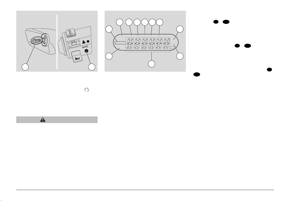
MULTIFUNCTION LIQUID CRYSTAL DISPLAY
When the ignition key (1) is set to ≈≈, all
segments of the multifunction display come
on (this is a test of all components). The
display resumes the last function set after
the vehicle was stopped.
CAUTION
After the first 1000 kilometres and every
6000 kilometres afterwards, a SERVICE
warning is displayed.
When you see this message, contact an
aprilia Official Dealer to have the
vehicle serviced as specified in the
periodic maintenance chart, see page
44 (PERIODIC MAINTENANCE CHART).
5 6 7 8 9 10
4
Km/h
AVG V
BATT
mph
SERVICE
ml/G Vmax
LAP
3
11
˚C
˚F
CEV
12
13
The different functions are selected and
displayed by pressing the MODE button (2)
placed on left side of the handlebar.
The segments of the multifunction display
are:
Lap timer indicator (3), service term icon
(4), average mph speed icon (5) (used on
versions ( ) only), average speed
USA
UK
(6), battery charge icon (7), average kph
speed icon (8) (the same icon is used for
"consumption" indication expressed in
Km/l), consumption expressed in mi/Gal.
(used on versions ( ) only) (9),
USA
UK
maximum speed icon (10), icon of the external temperature expressed in Celsius
degrees (° C) (11), icon of the external
temperature expressed in Fahrenheit degrees (° F) (12) (used on versions (
) only), six-digit reading of the set
UK
USA
functions identified by the corresponding
icons (13).
use and maintenance Scarabeo 500 ABS
21
Press the MODE button repeatedly to select in the order:
External temperature in ° C
MODE
Maximum speed (Vmax) + kph or mph
MODE
Average speed AVG (kph or mph)
MODE
Battery charge (Vbatt)
MODE
Fuel consumption (km/l or mi/Gal.)
MODE
Lap timer (LAP)
MODE
Kilometres till next service
(SERVICE)
MODE
14
RESETTING AVERAGE AND MAXIMUM
SPEED, FUEL CONSUMPTION AND LAP
TIMER
NOTE These indications may only be
reset when the odometer is displayed on
the right digital display.
◆ Press the TRIP key (14) for more than three
seconds.
NOTE The displayed function will be reset.
LAP TIMER START/STOP AND RESET
NOTE These indications may only be
reset when the odometer is displayed on
the right digital display.
START/STOP:
Press the MODE key for more than three
seconds.
RESET:
◆ Press the TRIP key (14) for more than three
seconds only when the lap timer is stopped.
15
I
D
ZA
PUSH
16 17 18
19
ODO TRIP 1 TRIP 2
DIGITAL ODOMETER
NOTE The displays only operate when
the ignition switch is set to ≈≈.
When the ignition key (15) is set to ≈≈ ,
all segments of the display come on to test
components for proper operation. The initial display shows the odometer.
The segments of the Display are:
Odometer display icon (16), TRIP 1 display
icon (17), TRIP 2 display icon (18), and
five-digit reading of selected indication
(19).
use and maintenance Scarabeo 500 ABS
22
2
I
D
A
Z
PUS
1
H
3
Press the TRIP key repeatedly to access in
the order:
Odometer (ODO)
TRIP
Trip meter 1
TRIP
Trip meter 2
TRIP
RESETTING TRIP 1 AND TRIP 2
◆ Press the TRIP key (1) for more than
three seconds when the TRIP meter you
wish to reset is displayed.
NOTE The function displayed currently
will be reset.
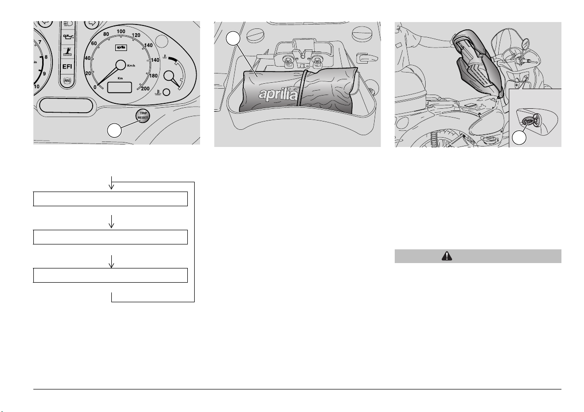
TOOL KIT
The tool kit (2) is placed under the saddle.
To reach it:
Release the saddle lock, see page 19
(STEERING LOCK) and lift the saddle.
The tool kit includes:
√ tool bag;
√ screwdriver "Fiat" l=128;
√ screwdriver handgrip;
√ 3 mm Allen wrench;
√ 4 mm Allen wrench;
√ lockring spanner for shock absorbers;
√ 16x140 spark plug socket with 12 mm
square and gasket;
√ spark plug socket extension;
√ 8x120 mm rod.
UNLOCKING/LOCKING THE SADDLE
◆ Insert the key (3) into the ignition switch.
◆ Press and turn the ignition key (3)
clockwise.
◆ To lock the saddle, lower it and then
press down moderately until the lock
becomes engaged.
WARNING
Make sure the saddle is locked securely
before riding.
use and maintenance Scarabeo 500 ABS
23

3
7
2
6
I
D
A
Z
P
U
S
H
1
4
5
GLOVE COMPARTMENT
The glove compartment can accommodate
bulky objects when you leave your bike unattended.
◆ Insert the key into the glove
compartment lock (1).
◆ Turn the key clockwise.
◆ The glove compartment flap (2) will open
automatically.
use and maintenance Scarabeo 500 ABS
24
SMALL STORAGE COMPARTMENT
◆ Push on the top section of the door (4).
◆ The door clicks open to give access to
the compartment.
◆ To close the door, push gently until
hearing an audible click.
◆ A 12V outlet (3) is inside the glove com-
partment.
◆ A 12V power socket (3) is fitted inside
the glove compartment to recharge small
appliances rated up to 180 W (mobile
phone, inspection lamp, etc.).
Power is supplied only when the engine
is running.
WARNING
Prolonged use of the power socket with
the engine stopped may flatten the
battery.
REAR TOP BOX
◆ Insert the key (5) into the ignition switch
(6).
◆ Push in the ignition key (5) and turn
anticlockwise.
◆ Lift the rear top box cover (7).
◆ To lock the top box cover, lower and
press down gently until you hear an
audible click.
WARNING
Ensure the rear top box is securely
locked before riding.
1
1
4
2
3
3
3
1
A
2
2
B
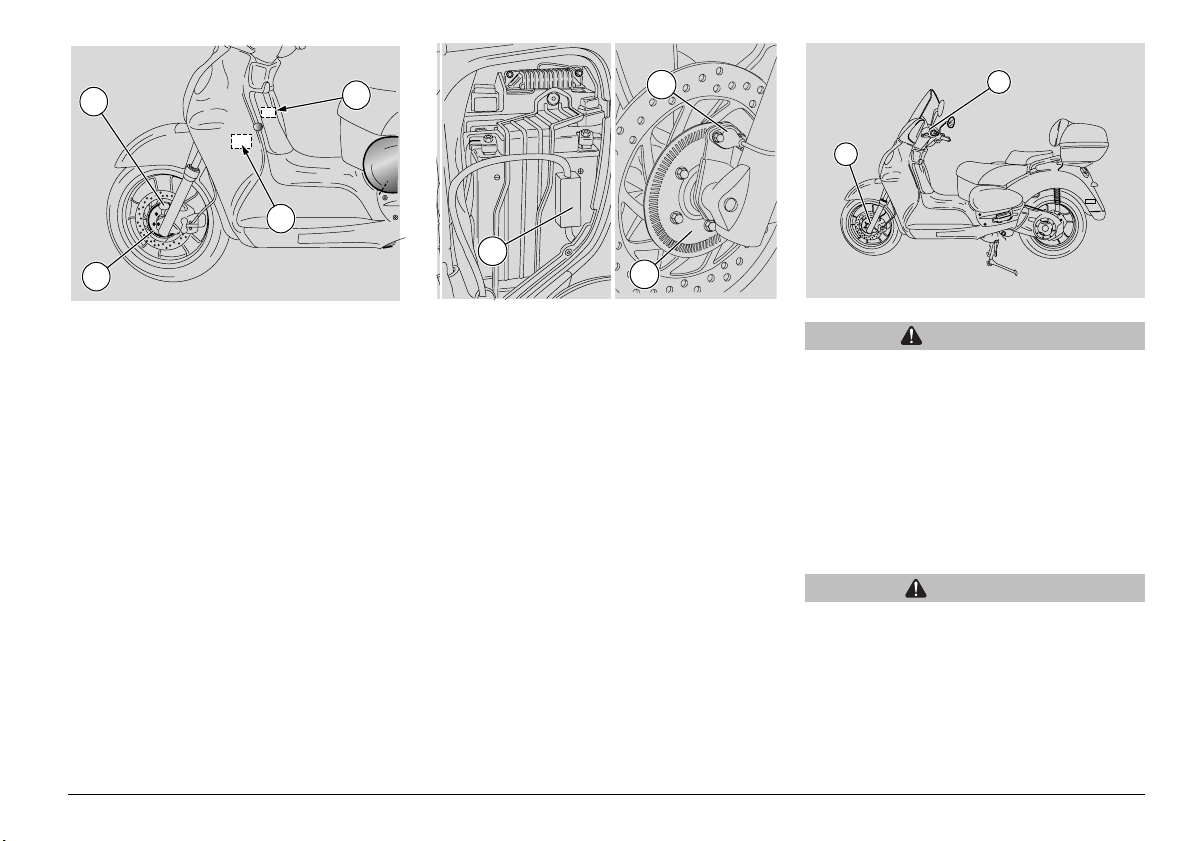
ABS
This vehicle is fitted with integral braking
system as well as servo brake and ABS in
the front wheel. Thanks to the servo brake,
vehicle braking power is higher than in
standard braking system.
ABS prevents front wheel locking in case
of emergency braking, thus increasing vehicle stability.
Emergency braking may cause the wheel
to lock in standard braking systems: the
tyre may therefore lose grip and the rider
may lose control of his/her vehicle.
This vehicle features a position sensor (1),
which ≈reads∆ position values on the phonic wheel (2) -integral with the front wheeland therefore possible wheel locking.
A control unit (4) manages braking signals
and therefore pressure into the braking
system. It therefore allows improved braking deceleration due to the front wheel antilock system and braking force distribution
through the integral braking system.
30A fuse (3)
Safeguarding: ABS control unit power circuit
NOTE Servo brake and ABS page 15
(INSTRUMENTS AND INDICATORS
TABLE) are not enabled when the ignition
is off or in case of failure.
WARNING
Wheel anti-lock braking system does
not safeguard the rider from falling
while turning. Emergency stops when
the motorcycle is bending or handlebar
is turned onto bumpy or slippery roads
or under slippery conditions will lead to
vehicle instability which can hardly be
controlled. Ride carefully and brake
gradually. Do not ride fast in vain hope
to be safe.
CAUTION
When braking while bending or turning,
the motorcycle is subject to physics
laws even if equipped with ABS.
use and maintenance Scarabeo 500 ABS
25
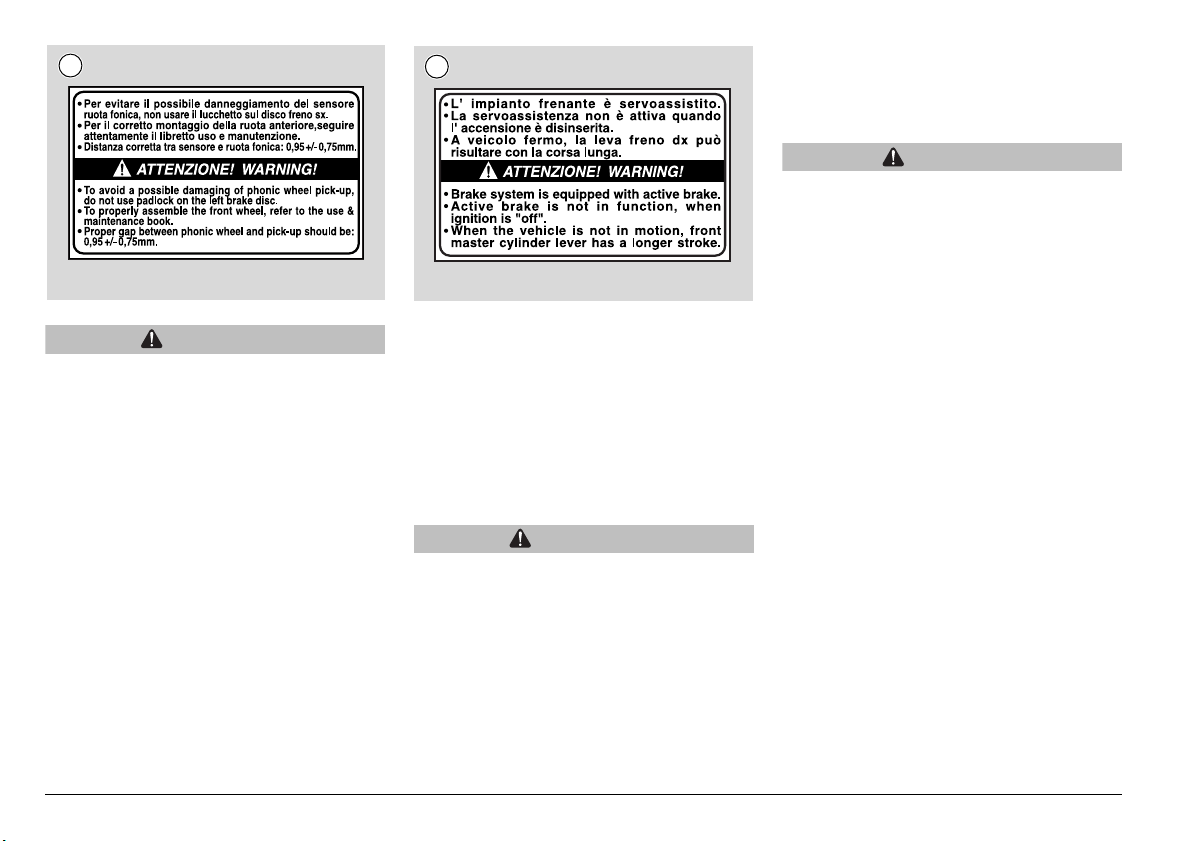
A
WARNING
In standard vehicles, the integral
braking system is enabled only by
pulling the left brake lever. In this way,
the braking force is applied to the right
brake disc in both wheels after being
duly delayed by a proper valve.Servocontrolled braking (in ABS) boosts
braking efficiency as oil pressure is
increased by an electro-hydraulic pump
while applying the brakes. Vehicles
featuring ABS apply integral braking
and servo-controlled braking at the
same time.
B
ABS lowers servo brake controlled pressure as soon as the phonic wheel sensor
(1) reads immediate front wheel locking.
The motorcycle features a 1-channel ABS
as it only works on the front wheel.
Check that the phonic wheel (2) is neither
warped nor damaged at very short intervals and sensor (1) is equidistant to all
wheel points (360°) at regular intervals.
WARNING
Do not use anti-theft devices locking
the brake disc otherwise the phonic
wheel might damage. Do not padlock
left brake disc.
NOTE Should the front wheel be
removed, check that the phonic wheel (2)
is 0.95 mm Ø 0.75 mm from sensor (1) after
wheel installation.
CAUTION
When removing and installing the front
wheel, do not damage sensor cable,
phonic wheel and sensor. Do not apply
brakes if brake calipers are not fitted to
the vehicle.
When installing the wheel, ensure that
sensor is properly positioned.
use and maintenance Scarabeo 500 ABS
26

MAIN COMPONENTS
FUEL
WARNING
The fuel used to operate engines is highly
flammable and becomes explosive under
particular conditions. Refuelling and
engine service should take place in a
well-ventilated area with the engine
stopped. Do not smoke when refuelling or
in the proximity of sources of fuel
vapours. Avoid contact with open flames,
sources of sparks or any other source
which may ignite the fuel or lead to
explosion. Take care not to spill fuel out
of the filler, or it may ignite when in
contact with hot engine parts. In the event
of accidental fuel spillage, make sure the
affected area is fully dry before starting
the engine. Fuel expands from heat and
when left under direct sunlight. Never fill
the fuel tank up to the rim. Tighten the
filler cap securely after each refuelling.
Avoid contact with skin. Do not inhale
vapours. Do not swallow fuel. Do not
transfer fuel between different containers
using a hose.
DO NOT RELEASE FUEL INTO THE
ENVIRONMENT.
KEEP AWAY FROM CHILDREN.
Use only premium-grade unleaded fuel
with a minimum octane rating of 91 (RON)
and 81 (MON).
TANK CAPACITY (reserve included):
√ 17
I
D
A
Z
PU
SH
2
1
To reach the filler cap:
◆ Insert the key (1) into the ignition switch.
◆ Push in the ignition key (1) and turn
clockwise.
◆ Unscrew the filler cap (2).
FUEL RESERVE :
√ 2
use and maintenance Scarabeo 500 ABS
27
 Loading...