

Page 1
RSV 1000 R - RSV 1000 R FACTORY
8104953
Page 2
© 2005 Piaggio & C. S.p.A. - Noale (VE)
First edition: December 2005
Reprint: September 2006/A
Produced and printed by:
VALLEY FORGE DECA
Ravenna , Modena, Torino
DECA S.r.l.
Registered & Admin. Offices
Via Vincenzo Giardini, 11
48022 Lugo (RA) - Italy Tel. 0545-216611
Fax 0545-216610
www.vftis.com
deca@vftis.spx.com
on behalf of:
Piaggio & C. S.p.A.
via G. Galilei, 1 - 30033 Noale (VE) - Italy
Tel. +39 - 041 58 29 111
Fax +39 - 041 44 10 54
www.aprilia.com
SAFETY WARNINGS
The following precautionary warnings are
used throughout this manual in order to
convey the following messages:
Safety warning. When you find this
symbol on the vehicle or in the
manual, be careful to the potential risk
of personal injury. Non-compliance
with the indications given in the
use and maintenance RSV 1000 R - RSV 1000 R FACTORY
2
messages preceded by this symbol may
result in major risks for your and other
people’s safety and for the vehicle!
WARNING
Indicates a potential hazard which may
result in serious injury or even death.
CAUTION
Indicates a potential hazard which may
result in minor personal injury or
damage to the vehicle.
NOTE The word “NOTE” in this manual
precedes important information or
instructions.
TECHNICAL INFORMATION
The operations preceded by this
symbol must be repeated also on
the opposite side of the vehicle.
If not expressly indicated otherwise, for the
reassembly of the units repeat the
disassembly operations in reverse order.
The terms “right” and “left” are referred to
the rider seated on the vehicle in the
normal riding position.
If the glove/tool kit compartment cover has
been installed (as an alternative to the
passenger seat), the transport of
passenger, luggage or objects is forbidden.
WARNING
The adjustments for the use of the
vehicle on racetracks must be carried
out exclusively in case of organized
races or events that take place on
isolated circuits, away from public
roads and with the consent of the
competent authorities.
It is strictly prohibited to carry out
adjustments for the use of the vehicle
on racetracks and then ride it on roads
or motorways.
WARNINGS - PRECAUTIONS GENERAL ADVICE
Before starting the engine, carefully read
this manual and in particular the section
“SAFE DRIVE”.
Your and other people’s safety depends
not only on your quickness of reflexes and
on your agility, but also on what you know
about the vehicle, on its efficiency and on
your knowledge of the basic information for
“SAFE DRIVE”.
Therefore, get a thorough knowledge of
the vehicle, in such a way as to be able to
drive in the traffic safely.
Page 3
NOTE This manual must be considered
as an integral part of the vehicle and must
always accompany it, even in case of
resale.
aprilia has carried out this manual with
the maximum attention, in order to supply
the user with correct and updated
information. However, since
constantly improves the design of its
products, there may be slight
discrepancies between the characteristics
of your vehicle and those described in this
manual.
For any clarification concerning the
information contained in this manual, do
not hesitate to contact your
Official dealer .
For control and repair operations not
expressly described in this publication, for
the purchase of
parts, accessories and other products, as
well as for specific advice, contact
exclusively
and Service Centers, which guarantee
prompt and accurate assistance.
Thank you for choosing
you a nice ride.
All rights as to electronic storage,
reproduction and total or partial adaptation,
with any means, are reserved for all
Countries.
aprilia genuine spare
aprilia Authorised Dealers
aprilia. We wish
aprilia
aprilia
NOTE In some countries the
antipollution and noise regulations in force
require periodical inspections.
The user of the vehicle in these countries
must:
√ contact an
have the non-homologated components
replaced with others homologated for
use in the country in question;
√ carry out the required periodical
inspections.
aprilia Official dealer to
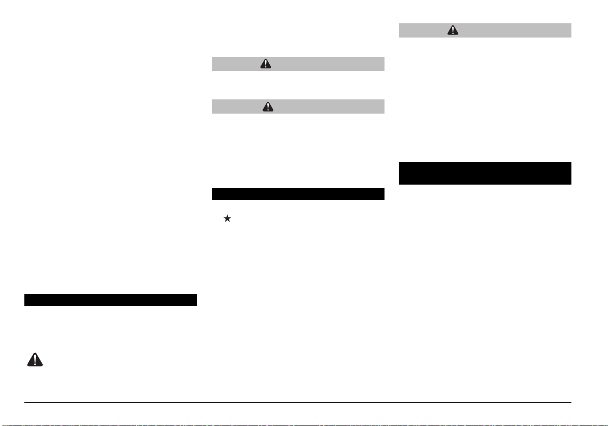
NOTE Soon after purchasing the
vehicle, write down the identification data
indicated on the SPARE PARTS
IDENTIFICATION LABEL in the table here
below. This label is positioned on the left
side of the frame; to read it, it is necessary
to remove the rider seat, see p. 80
(REMOVING THE RIDER SADDLE).
These data indicate:
√ year of manufacture (Y, 1, 2, ...);
√ modification code (A, B, C, ...);
√ homologation country (I, UK, A, ...).
and are to be supplied to the
Official dealer as reference data for the
purchase of spare parts or specific
accessories of the model you have
acquired.
aprilia
In this manual the various versions are
indicated by the following symbols:
RSV 1000 R
RSV 1000 R FACTORY
optional
catalytic
VERSION:
Italy Singapore
United Slovenia
Austria Israel
Portugal South Korea
Finland Malaysia
Belgium Chile
Germany Croatia
France Australia
Spain
Greece Brazil
Holland
Switzerland New Zealand
Denmark Canada
Japan
United States
of America
South Africa
use and maintenance RSV 1000 R - RSV 1000 R FACTORY
3
Page 4

GENERAL INDEX
SAFETY WARNINGS................................................. 2
TECHNICAL INFORMATION..................................... 2
WARNINGS - PRECAUTIONS - GENERAL ADVICE 2
GENERAL INDEX................................................. 4
BASIC SAFETY RULES ....................................... 6
CLOTHING ........................................................... 9
ACCESSORIES .................................................. 10
LOAD .................................................................. 10
ARRANGEMENT OF THE MAIN ELEMENTS ........ 12
ARRANGEMENT OF THE
INSTRUMENTS/CONTROLS................................... 14
INSTRUMENTS AND INDICATORS........................ 15
INSTRUMENTS AND INDICATORS TABLE ...... 16
MULTIFUNCTION COMPUTER ......................... 18
KEY CONTROLS ..................................................... 25
CONTROLS ON THE RIGHT SIDE OF THE
HANDLEBAR...................................................... 25
CONTROLS ON THE LEFT SIDE OF THE
HANDLEBAR...................................................... 25
IGNITION SWITCH............................................. 26
STEERING LOCK ............................................... 27
ACCESSORIES........................................................ 28
UNLOCKING/LOCKING THE
PASSENGER SEAT ........................................... 28
UNLOCKING/LOCKING THE GLOVE/TOOL KIT
COMPARTMENT COVER .................................. 29
GLOVE/TOOL KIT COMPARTMENT ................. 30
LUGGAGE FIXING POINTS ............................... 30
SPECIAL TOOLS ......................................... 31
ACCESSORIES .................................................. 31
MAIN COMPONENTS .............................................. 32
FUEL................................................................... 32
BRAKE FLUID - recommendations..................... 33
DISK BRAKES .................................................... 34
FRONT BRAKE .................................................. 35
REAR BRAKE..................................................... 37
CLUTCH FLUID - recommendations .................. 38
CLUTCH ............................................................. 39
COOLANT........................................................... 40
TYRES ................................................................ 43
ENGINE OIL ....................................................... 44
ADJUSTING THE FRONT BRAKE LEVER AND
THE CLUTCH LEVER ........................................ 45
ADJUSTING REAR BRAKE LEVER
CLEARANCE ...................................................... 45
ADJUSTING THE REAR BRAKE LEVER AND THE
GEAR SHIFT LEVER ......................................... 46
MUFFLER/EXHAUST SILENCER ..................... 46
INSTRUCTIONS FOR USE ..................................... 47
GETTING ON AND OFF THE VEHICLE ........... 47
PRE-RIDE CHECKS .......................................... 49
PRE-RIDE CHECKS CHART............................. 50
STARTING ......................................................... 51
MOVING OFF - RIDING..................................... 53
RUNNING-IN...................................................... 56
STOPPING......................................................... 57
PARKING ........................................................... 57
PLACING THE VEHICLE ON THE STAND....... 58
SUGGESTIONS TO PREVENT THEFT ............ 58
MAINTENANCE ...................................................... 59
PERIODIC MAINTENANCE CHART ................. 61
IDENTIFICATION DATA .................................... 63
JOINTS WITH CLICK CLAMPS AND WITH
SCREW CLAMPS .............................................. 63
CHECKING AND TOPPING UP ENGINE OIL
LEVEL................................................................ 64
CHANGING ENGINE OIL AND THE ENGINE OIL
FILTER............................................................... 65
AIR CLEANER ................................................... 68
FITTING THE PINS FOR THE REAR WHEEL
STAND ......................................................... 70
PLACING THE VEHICLE ON THE REAR WHEEL
STAND ......................................................... 70
PLACING THE VEHICLE ON THE FRONT
WHEEL STAND ........................................... 71
FRONT WHEEL ................................................. 71
FRONT BRAKE CALLIPERS ............................. 74
REAR WHEEL ................................................... 75
DRIVE CHAIN .................................................... 78
REMOVING THE RIDER SADDLE .................... 80
LIFTING THE FUEL TANK ................................ 80
REMOVING THE SIDE FAIRINGS .................... 81
REMOVING THE LOWER FAIRING.................. 81
REMOVING THE SIDE PANELS ....................... 82
REMOVING THE FAIRING UPPER FRONT
COVERS ............................................................ 82
REMOVING THE REAR-VIEW MIRRORS ........ 83
REMOVING THE FRONT FAIRING .................. 84
REMOVING THE SIDE STAND ......................... 85
INSPECTING THE FRONT AND REAR
SUSPENSION.................................................... 87
FRONT SUSPENSION ...................................... 87
≈R FACTORY∆ FORK......................................... 88
STEERING DAMPER......................................... 89
REAR SUSPENSION......................................... 90
CHECKING THE BRAKE PADS FOR WEAR.... 92
THROTTLE TWISTGRIP ADJUSTMENT .......... 93
SPARK PLUGS .................................................. 94
CHECKING THE SIDE STAND.......................... 96
BATTERY........................................................... 97
CLEANING AND CHECKING BATTERY
TERMINALS AND LEAD CONNECTIONS ........ 97
BATTERY REMOVAL ........................................ 98
CHECKING BATTERY FLUID LEVEL ............... 99
CHARGING THE BATTERY .............................. 99
INSTALLING THE BATTERY........................... 100
LONG INACTIVITY OF THE BATTERY........... 101
CHECKING THE SWITCHES .......................... 101
REPLACING THE FUSES ............................... 102
VERTICAL ADJUSTMENT OF THE
HEADLIGHT BEAM.......................................... 103
HEADLIGHT SCREENING .............................. 104
BULBS.............................................................. 105
REPLACING THE DASHBOARD BULBS........ 105
REPLACING THE HEADLIGHT BULBS .......... 106
REPLACING THE FRONT AND REAR DIRECTION
INDICATOR BULBS......................................... 107
REPLACING THE NUMBER PLATE
LIGHT BULB .................................................... 108
TRANSPORT......................................................... 109
CLEANING ............................................................ 109
LONG PERIODS OF INACTIVITY ................... 111
TECHNICAL DATA ............................................... 112
LUBRICANT CHART........................................ 116
WIRING DIAGRAM- RSV 1000 R -
RSV 1000 R FACTORY ................................... 118
WIRING DIAGRAM KEY - RSV 1000 R -
RSV 1000 R FACTORY ................................... 119
Official Dealers and Service Centres ............... 120
use and maintenance RSV 1000 R - RSV 1000 R FACTORY
4
Page 5

safe drive
Page 6
BASIC SAFETY RULES
To drive the vehicle it is necessary to be in
possession of all the requirements
prescribed by law (driving licence,
minimum age, psychophysical ability,
insurance, state taxes, vehicle registration,
number plate, etc.).
Gradually get to know the vehicle by
driving it first in areas with low traffic and/or
private areas.
use and maintenance RSV 1000 R - RSV 1000 R FACTORY
6
The use of medicins, alcohol and drugs or
psychotropic substances notably increases
the risk of accidents.
Be sure that you are in good
psychophysical conditions and fit for
driving and pay particular attention to
physical weariness and drowsiness.
Most road accidents are caused by the
driver»s lack of experience.
NEVER lend the vehicle to beginners and,
in any case, make sure that the driver has
all the requirements for driving.
Page 7
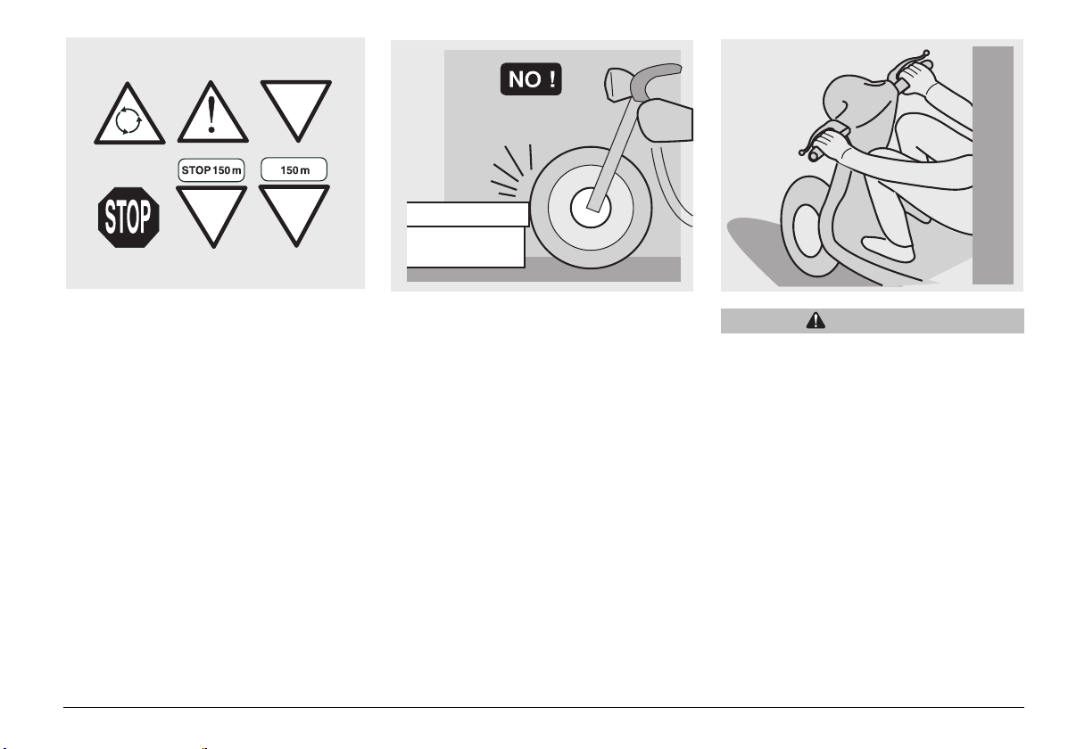
Rigorously observe all road signs and
national and local road regulations.
Avoid abrupt movements that can be
dangerous for yourself and other people
(for example: proceeding on the back
wheel, speeding, etc.), and give due
consideration to the road surface, visibility
and other driving conditions.
Avoid obstacles that could damage the
vehicle or make you lose control.
Avoid riding in the slipstream created by
preceding vehicles in order to increase
your speed.
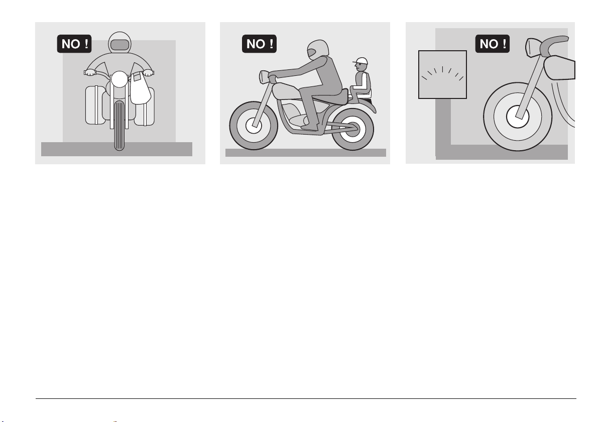
WARNING
Always drive with both hands on the
handlebars and both feet on the
footrests (or on the rider’s footboards),
in the correct driving posture.
Avoid standing up or stretching your
limbs while driving.
use and maintenance RSV 1000 R - RSV 1000 R FACTORY
7
Page 8
OIL
COOLER
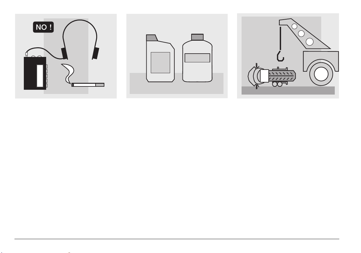
The driver should pay attention and avoid
distractions caused by people, things and
movements (never smoke, eat, drink, read,
etc.) while driving.
use and maintenance RSV 1000 R - RSV 1000 R FACTORY
8
Use only the vehicle»s specific fuels and
lubricants indicated in the "LUBRICANT
CHART"; regularly check oil, fuel and
coolant levels.
If the vehicle has been involved in an
accident, make sure that no damage has
occurred to the control levers, pipes, wires,
braking system and vital parts.
If necessary, have the vehicle inspected by
an
aprilia Official dealer who should
carefully check the frame, handlebars,
suspensions, safety parts and all the
devices that you cannot check by yourself.
Always remember to report any
malfunction to the technicians to help them
in their work.
Never use the vehicle when the amount of
damage it has suffered endangers your
safety.
Page 9
A12
345
ONLY ORIGINALS
Never change the position, inclination or
colour of: number plate, direction
indicators, lights and horns.
Any modification of the vehicle will result in
the invalidity of the warranty.
Any modification of the vehicle and/or the
removal of original components can
compromise vehicle performance levels
and safety or even make it illegal.
We recommend respecting all regulations
and national and local provisions regarding
the equipment of the vehicle.
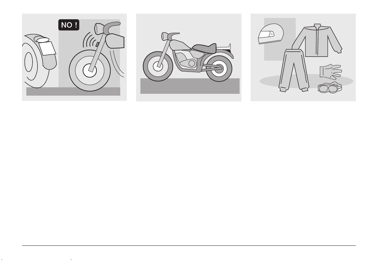
In particular, avoid all modifications that
increase the vehicle»s performance levels
or alter its original characteristics.
Never race with other vehicles.
Avoid off-road driving.
CLOTHING
Before starting, always wear a correctly
fastened crash helmet. Make sure that it is
homologated, in good shape, of the right
size and that the visor is clean.
Wear protective clothing, preferably in light
and/or reflecting colours. In this way you
will make yourself more visible to the other
drivers, thus notably reducing the risk of
being knocked down, and you will be more
protected in case of fall.
This clothing should be very tight-fitting
and fastened at the wrists and ankles;
strings, belts and ties should not be
hanging loose; prevent these and other
objects from interfering with driving by
getting entangled with moving parts or
driving mechanisms.
use and maintenance RSV 1000 R - RSV 1000 R FACTORY
9
Page 10
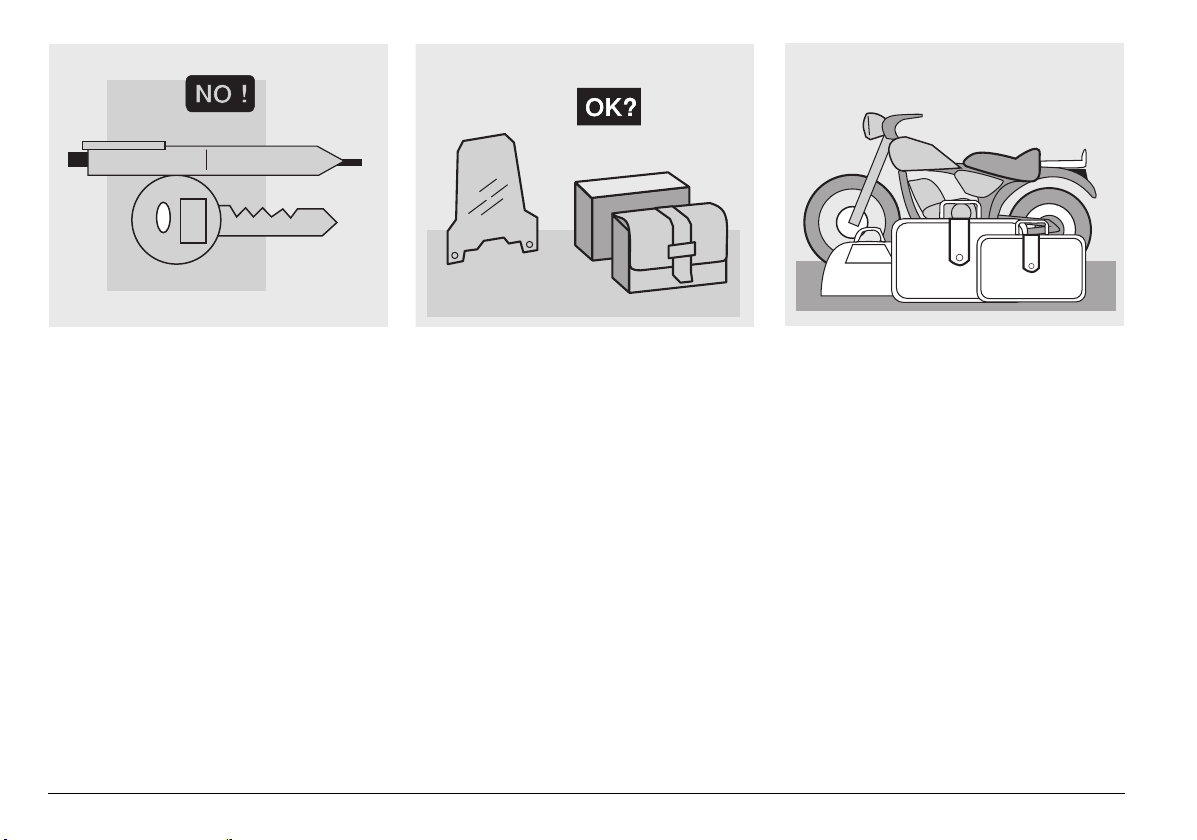
Do not keep objects that can be dangerous
in case of fall, for example pointed objects
like keys, pens, glass vials etc. in your
pockets (the same recommendations also
apply to passenger).
use and maintenance RSV 1000 R - RSV 1000 R FACTORY
10
ACCESSORIES
The owner of the vehicle is responsible for
the choice, installation and use of any
accessory.
Avoid installing accessories that cover
horns or lights or that could impair their
functions, limit the suspension stroke and
the steering angle, hamper the operation of
the controls and reduce the distance from
the ground and the angle of inclination in
turns.
Avoid using accessories that hamper
access to the controls, since this can make
reaction times longer during an
emergency.
Big fairings and windshields installed on
the vehicle may produce aerodynamic
forces that affect the stability of the vehicle,
especially when riding at high speed.
Make sure that the equipment is well
fastened to the vehicle and not dangerous
when driving.
Do not install electrical devices and do not
modify those already existing to avoid
electrical overloads, because the vehicle
could suddenly stop or there could be a
dangerous current shortage in the horn and
in the lights.
aprilia recommends the use of genuine
accessories (
aprilia genuine accessories).
LOAD
Be careful and moderate when loading
your luggage. Keep any luggage loaded as
close as possible to the center of gravity of
the vehicle and distribute the load evenly
on both sides, in order to reduce
unbalance to the minimum. Furthermore,
make sure that the load is firmly secured to
the vehicle, especially during long trips.
Page 11
KG!
Avoid hanging bulky, heavy and/or
dangerous objects on the handlebars,
mudguards and forks, because the vehicle
might respond more slowly in turns and its
manoeuvrability could be unavoidably
impaired.
Do not place bags that are too bulky or the
crash helmet on the vehicle sides and do
not ride with them on, because they could
hit people or obstacles, making you lose
control of the vehicle.
Do not carry any bag if it is not tightly
secured to the vehicle.
Do not carry bags which protrude too much
from the luggage-rack or which cover the
lights, horn or indicators.
Do not carry animals or children on the
glove compartment or on the luggage rack.
Do not exceed the maximum load allowed
for each luggage-rack.
When the vehicle is overloaded, its stability
and its manoeuvrability can be
compromised.
use and maintenance RSV 1000 R - RSV 1000 R FACTORY
11
Page 12
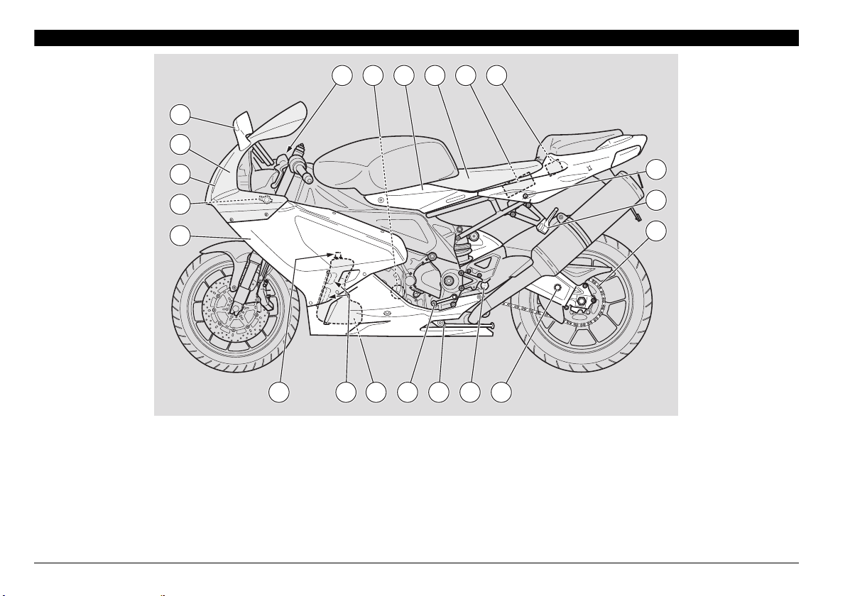
ARRANGEMENT OF THE MAIN ELEMENTS
5
4
8 97 10 116
3
2
1
KEY
1) Left side fairing
2) Adjustable steering damper
3) Headlight left lamp
4) Front fairing
5) Left rear-view mirror
10) Battery
11) Main fuse carrier (30 A)
12) Passenger seat lock
6) Clutch fluid reservoir
use and maintenance RSV 1000 R - RSV 1000 R FACTORY
12
2021
7) Engine oil filter
8) Left side panel
9) Rider seat
glove/tool kit compartment
19
15161718
13) Passenger left footrest
(snaps closed/open)
14) Drive chain
15) Rear swinging arm
16) Rider left footrest
17) Side stand
18) Gear shift lever
12
13
14
19) Engine oil tank
20) Engine oil level
21) Engine oil tank cap
Page 13
1398654 11 12107
3
14
2
1
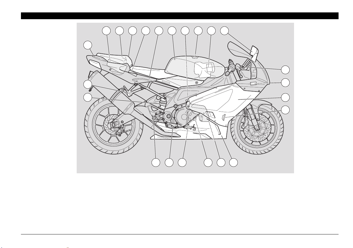
KEY
1) Rear shock absorber
2) Passenger right footrest
(snaps closed/open)
3) Tail light
4) Glove/tool kit compartment
5) Passenger seat (glove/tool
kit compartment cover)
22 1823
6) Passenger grab strap
7) Engine Control Unit
8) Right side panel
9) Fuel tank
10) Coolant expansion tank cap
11) Fuel tank filler cap
12) Air cleaner
192021
13) Right rear-view mirror
14) Front brake fluid reservoir
15) Secondary fuse carrier (15 A)
16) Right side fairing
17) Horn
18) Lower fairing
19) Expansion tank
use and maintenance RSV 1000 R - RSV 1000 R FACTORY
15
16
17
20) Rear brake fluid reservoir
21) Rear brake master cylinder
22) Rear brake lever
23) Rider right footrest
13
Page 14
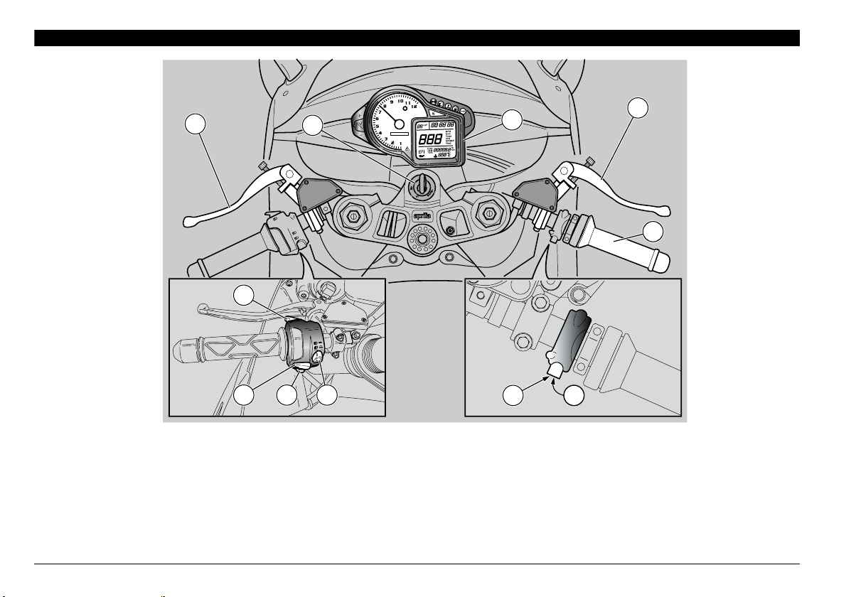
ARRANGEMENT OF THE INSTRUMENTS/CONTROLS
1
2
6
9
8
KEY
1) Clutch lever
2) Ignition/steering lock switch ( - - )
3) Instruments and indicators
4) Front brake lever
5) Throttle twistgrip
6) High beam flasher ()/LAP button (multifunction)
3
4
5
7
10 11
7) Light dimmer switch ( - )
8) Direction indicator switch ()
9) Horn button ()
10) Starter button ()
11) Engine kill switch ( - )
use and maintenance RSV 1000 R - RSV 1000 R FACTORY
14
Page 15
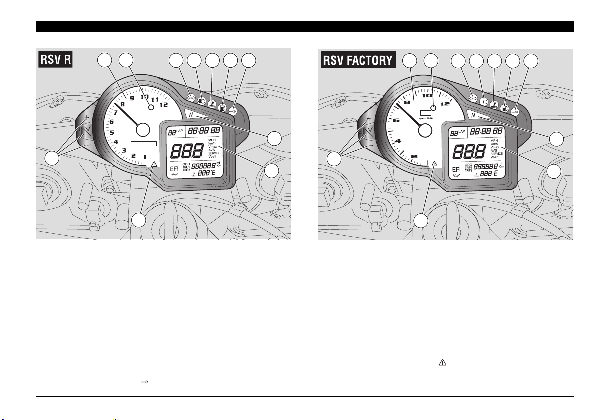
INSTRUMENTS AND INDICATORS
1 2
3 4 5 6 7
8
11
9
10
KEY
1) Rev counter
2) Red line light
3) Green direction indicator light ()
4) Blue high beam light ()
5) Amber "stand down" light ()
6) Amber low fuel light ()
7) Red immobilizer light ( ) (where immobilizer system is fitted)
1 2
3 4 5 6 7
11
10
8) Green neutral light ()
9) Multifunction digital display (coolant temperature - clock battery voltage - lap timer - engine oil pressure diagnostics
()
10) Red general warning light ( )
11) Multifunction computer programming buttons (+, Trip V, -)
8
9
use and maintenance RSV 1000 R - RSV 1000 R FACTORY
15
Page 16
INSTRUMENTS AND INDICATORS TABLE
When the ignition key is turned to "" with the engine stopped, all warning lights come on for a LED check-up and go out after three
seconds. If one or more warning lights do not come on at this stage, contact an
Description Function
Rev counter (rpm)
Gives engine revolutions per minute.
CAUTION
Never exceed engine max rpm, see page 56 (RUNNING-IN).
aprilia Official dealer.
Blinks when its operating threshold (max rpm, user-selectable) is exceeded, see page 23
(SETTING THE RED LINE THRESHOLD (WITH ENGINE OFF ONLY)).
Red line light
Comes on for three seconds when the maximum rpm threshold is confirmed during the
setting procedure, see page
ONLY))
. It also comes on for three seconds each time the ignition key is turned to "", see
23 (SETTING THE RED LINE THRESHOLD (WITH ENGINE OFF
page 18 (MULTIFUNCTION COMPUTER).
Direction indicator light
High beam light
Side stand light
Low fuel light
Anti-theft device (immobilizer) light
(where immobilizer system is fitted)
Neutral light
Blinks when the direction indicators are on.
Comes on when the high beam is on or when you flash the high beam
Comes on when the side stand is down
Comes on when there are about 4 litres of fuel left in the tank.
Refuel as soon as possible, see page 32 (FUEL).
Blinks when the engine is off as a deterrent to prevent theft. Indicates that the anti-theft system
is operating.
CAUTION
IMMOBILIZER system remains in operation.
Comes on when the gearbox is in neutral.
When the engine has not been started during 10 days in a row, the
energy-saving feature will cause the light to go out, but the
.
Comes on each time the ignition key is turned to ≈∆,with the engine stopped for a light
operation check-up.
Error light
If the light fails to come on at this stage, contact an
CAUTION
injection system failure (efi) has been detected, engine oil pressure is low () or
coolant temperature is too high (
and contact an aprilia
If it stays on , along with any one of the three display symbols
"
efi", "" and "",after engine is fired, it means that a fuel
). When this is the case, stop the engine immediately
Official dealer
aprilia Official dealer
use and maintenance RSV 1000 R - RSV 1000 R FACTORY
16
Page 17
Description Function
Speedometer (km/h - MPH)
Odometer ( KM - Mi)
Can be set to display current, average or maximum road speed (in kilometres
or miles) see page 18 (MULTIFUNCTION COMPUTER).
Gives total distance covered or distance covered since the trip meter
was last reset (in km or miles)
Indicates engine coolant temperature, see page 18 (MULTIFUNCTION
COMPUTER)
CAUTION
temperature. Consequently, temperature will rise further.
Coolant temperature
(°C/°F)
Multifunction
digital display
When temperature rises up to the danger zone, stop the engine, turn the
ignition key to "
Now turn the ignition key to "
(COOLANT).
Contact an aprilia
CAUTION
engine damage.
.
.
Do not leave the ignition switch set to "
will stop the cooling fans regardless of coolant
" and wait until the cooling fans switch off.
" and check coolant level, see page 40
Official dealer.
Exceeding the maximum coolant temperature
allowed (115 °C - 239 °F) may lead to severe
", as this
To cycle
through display
readouts, see
page 18 (MULTIFUNCTION
COMPUTER)
Clock
Battery voltage
V BATT
Lap timer
Diagnostics
Gives hours and minutes in accordance with selected settings, see page 18
(MULTIFUNCTION COMPUTER).
Indicates battery voltage, see page 18 (MULTIFUNCTION COMPUTER).
Indicates the various time measurements in accordance with selected
settings, see page 18 (MULTIFUNCTION COMPUTER).
Each time the ignition switch is set to position "
of the multifunction display for approximately three seconds.
CAUTION
most cases, thengine will keep running, although performance will be somewhat
reduced. Contact an aprilia
If the wording " " appears during normal engine operation, it
means that the Engine Control Unit has detected an anomaly. In
Official dealer immediately.
", the wording " " appears on the right side
use and maintenance RSV 1000 R - RSV 1000 R FACTORY
17
Page 18
2
1
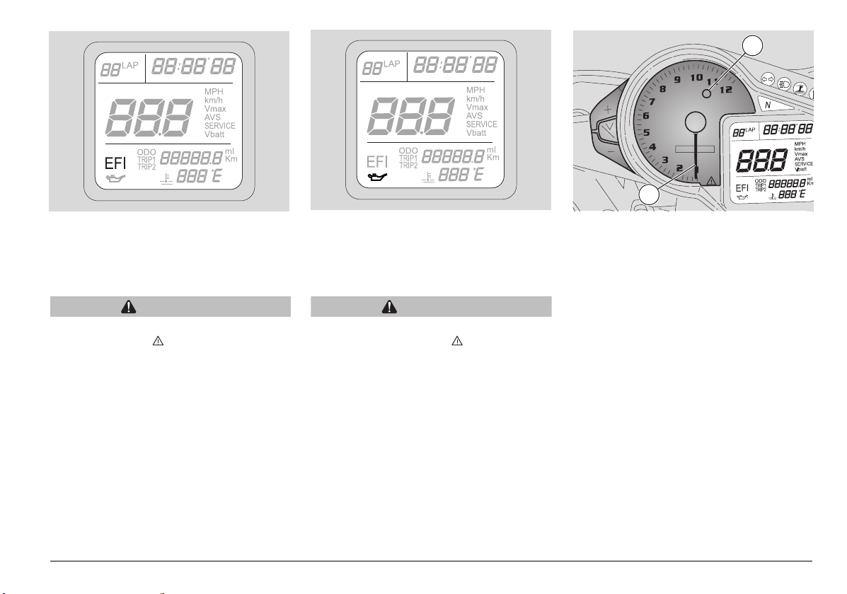
MULTIFUNCTION COMPUTER
When the ignition key is set to position "",
the following dashboard lights come on for
three seconds:
- all segments of the multifunction display;
- all warning lights;
- backlighting.
The rev counter pointer (1) moves to the
maximum rpm value set by the user. After
about three seconds, the red line light (2)
goes out and the rev counter pointer (1)
returns to its initial position.
During the initial check-up, all instruments will
briefly show the current values of the
corresponding parameters.
CAUTION
When an "ERR" message flashes on the
dashboard instead of the water
temperature and the stand and red line
lights stay on with a steady light, it means
that there is a communication problem on
the CAN line between dashboard and
Engine Control Unit. Contact a dealer.
use and maintenance RSV 1000 R - RSV 1000 R FACTORY
18
CAUTION
After covering the first 1000 km, the
"SERVICE" icon appears on the
multifunction display. The icon is
displayed again upon reaching 10,000
km and every 10,000 km afterwards.
Contact an
have the vehicle serviced as specified
in the periodic maintenance chart, see
page 61 (PERIODIC MAINTENANCE
CHART). To turn off the "SERVICE"
warning, hold down the "+" and "-"
buttons for at least 15 seconds upon
turning the key to on.
aprilia Official dealer to
With the ignition key in position "",
standard display readouts are as follows:
√ current speed
√ clock
√ coolant temperature
√ odometer.
TOGGLING BETWEEN MEASUREMENT
UNITS (km-mi, kph-MPH, °C-°F)
u Hold down the "TRIP/V" and "-" buttons
together for over 15 seconds to toggle
between km and mi and between kph
and MPH.
u Likewise, hold down the "TRIP/V" and
"+" buttons together for over 15 seconds
to toggle between °C and °F.
Page 19
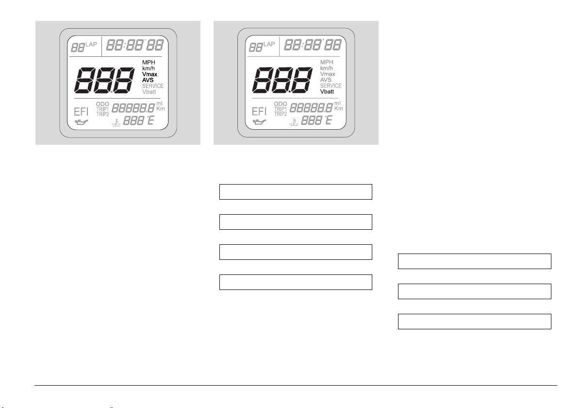
VIEWING CURRENT, MAXIMUM AND
AVERAGE SPEEDS AND BATTERY
VOLTAGE
NOTE Average and maximum speed
and battery voltage are only displayed
when the vehicle is stopped. Only current
speed may be displayed while riding.
When the ignition key is turned to position
"", current speed appears on the display.
Press the "+" button to display maximum
speed (V max), average speed (AVS) and
battery voltage.
↓ +
Current speed
↓ +
Maximum speed
↓ +
Average speed
↓ +
Battery voltage
↓ +
To reset maximum (V max) and average
speed (AVS), select the speed indication
you wish to reset and hold down the "-"
button for at least 3 seconds.
NOTE Maximum and average speeds
are calculated on the distance covered
since last resetting.
Battery voltage indication (expressed in
Volts) cannot be changed and provides a
measure of battery operating conditions.
The charging system is operating correctly
when battery voltage at 4000 rpm with the
low beam on is between 13 and 15 Volts.
u Setting instrument backlighting:
instrument backlighting brightness can
be set at one of three preset levels (30%,
70%, 100%). To set backlighting, press
the "-" button within 5 seconds of turning
the key to "".
↓ -
30% brightness
↓ -
70% brightness
↓ -
100% brightness
↓ -
use and maintenance RSV 1000 R - RSV 1000 R FACTORY
19
Page 20
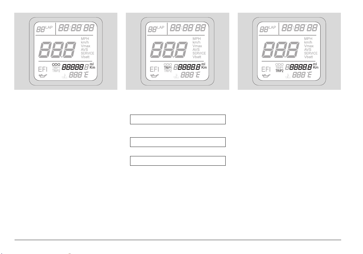
ODOMETER AND TRIP METER
DISPLAY (TRIP 1 AND TRIP 2)
Turn the ignition key to "", to display the
odometer. To switch to the trip meter
(km/mi) (TRIP 1 and TRIP 2), press the
Trip/V button.
use and maintenance RSV 1000 R - RSV 1000 R FACTORY
20
↓ TRIP/V
ODOMETER
↓ TRIP/V
TRIP 1
↓ TRIP/V
TRIP 2
↓ TRIP/V
To reset TRIP 1, select Trip 1 display and
hold down the "Trip/V" button for at least 3
seconds.
To reset TRIP 2, select Trip 2 display and
hold down the "Trip/V" button for at least 3
seconds.
NOTE Trip meter indications reflect the
distance covered since last resetting.
u Trip 1 and Trip 2 indications are wiped
off when the battery is disconnected.
Page 21
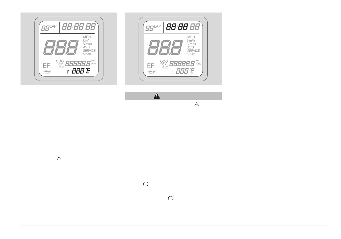
COOLANT TEMPERATURE DISPLAY
√ The coolant temperature display reads
---" when the sensor detects a
"
temperature below 34°C (93°F).
√ When the sensor detects a temperature
between 35°C (95°F) and 114°C
(237°F), the display provides actual
temperature indication.
√ Temperatures between 115° C (239° F)
and 135°C (275°F) are displayed with a
flashing indication. In addition, the
warning light will come on to indicate
a dangerous condition.
√ The display will flash for temperatures
above 135°C (275°F) (again, the
warning light comes on).
CAUTION
The dashboard error light ( ) coming
on indicates a damaged or
disconnected coolant temperature
sensor, resulting in missing
temperature reading. When this is the
case, contact an
aprilia Official dealer.
Display temperature range: 35-135°C (95275 °F).
SETTING THE DIGITAL CLOCK:
The digital clock is displayed in the top
area of the screen.
The clock is only displayed when the key is
set to ≈∆.
NOTE The clock may only be set when
the key is set to " " and the motorcycle
is at standstill.
HOUR SETTING
u Hold down the buttons "+" and "-" for at
least 3 seconds, until the hour digits
begin to flash.
u Use the "+" and "-" buttons to set hours
as desired.
u Hold down either of the buttons and
current setting will increase/decrease by
one unit per second.
u Hold down the "TRIP/V" button for at
least three seconds to confirm hour
setting. The clock will automatically
switch to the minutes setting mode.
MINUTES SETTING
u Pressing the "+" and "-" buttons
increases/decreases current setting by
one minute.
Hold down either of the buttons to
increase/decrease current setting by one
unit per second.
u Hold down the "TRIP/V" button for at
least 3 seconds, until the minute digits
stop flashing, to confirm your new
setting.
u Clock setting is lost when the battery is
disconnected.
use and maintenance RSV 1000 R - RSV 1000 R FACTORY
21
Page 22
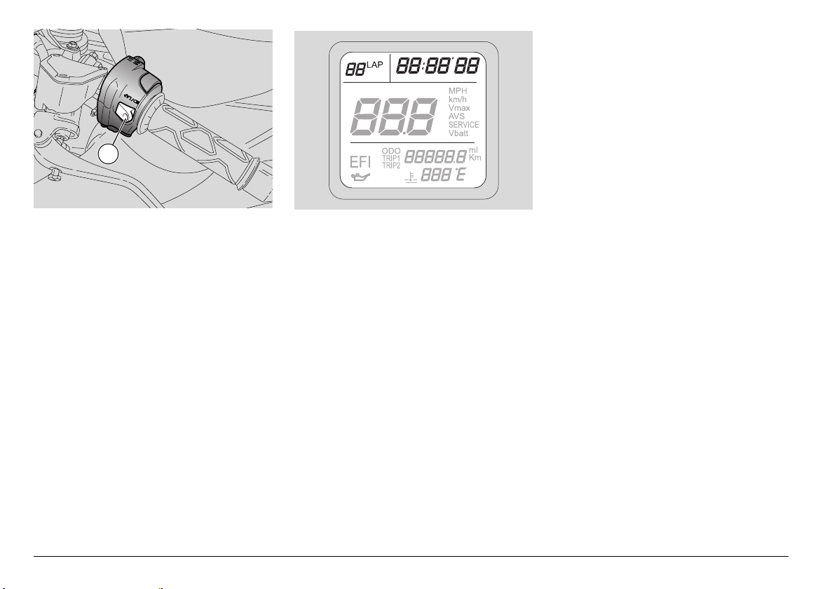
6
LAP TIMER
The lap timer measures and stores lap
times while riding on the track for later
review.
When the "LAP TIMER" function is
selected, the "clock" cannot be displayed:
To turn on the lap timer:
u Hold down "TRIP/V" for over 3 seconds
while holding down the "LAP" button.
The clock display area will read "01 LAP
00'00"00"
To turn off the lap timer:
u Hold down "TRIP/V" for over 3 seconds
while holding down the "LAP" button.
The display will return to the clock
display.
.
To start the lap timer
u Press the "LAP" button (6) and release
immediately. At the first press, time
count starts.
Pressing the "LAP" button again within
10 seconds of starting the time count will
reset and restart the time count
At the next press of the "LAP" button, a
new lap time count begins. The previous
lap time is stored and displayed for 10
seconds along with lap number (in the
top left corner)
After these 10 seconds, lap timer display
changes to second lap timing and lap
number.
NOTE The lap timer can store up to 40
lap times. When memory is full, pressing
the "LAP" button (6) will take no effect and
the 40 lap times stored are displayed
automatically.
The lap timer is reset by deleting the 40 lap
times stored as follows.
Access the lap timer function and hold
down the "-" button for at least 3 seconds
while holding down the LAP button (6).
When the memory is clear, the lap timer
goes back to the initial display "
00'00"00"
Any lap times stored will be lost when the
battery is disconnected.
How to view stored lap times:
u Access the lap timer function and hold
down "TRIP/V" for over 3 seconds. Scroll
through lap times using buttons "+"
(scroll forward) and "-" (scroll back).
To go back to the lap timer function, hold
down "TRIP/V" for over 3 seconds.
.
01 LAP
use and maintenance RSV 1000 R - RSV 1000 R FACTORY
22
Page 23
1
2
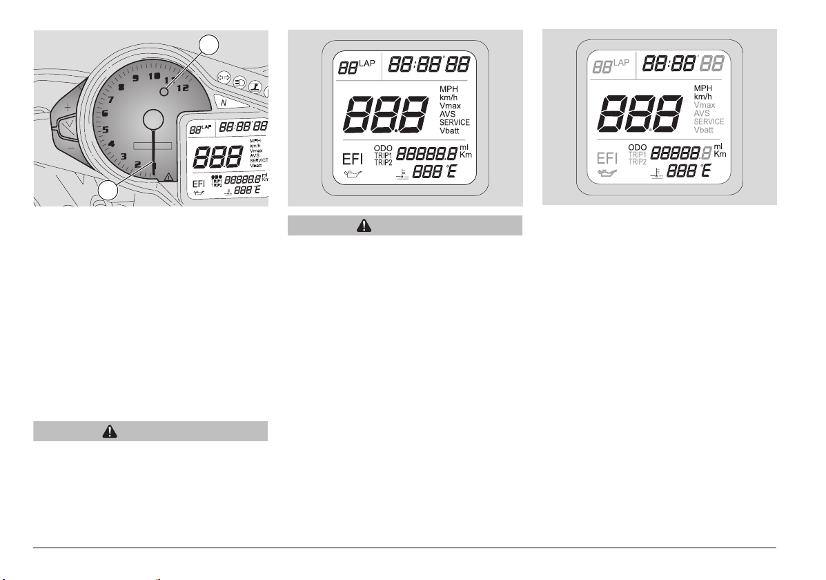
DIAGNOSTICS
1) Each time the ignition key is set to "",
the wording "
three seconds.
efi" is displayed for about
CAUTION
When the "efi" wording turns on and the
warning light ( ) comes on during
normal engine operation, it means that
the Engine Control Unit has detected an
anomaly.
In most cases the engine will keep
running, although with less than ideal
performance. However, contact an
aprilia Official Dealer without delay.
ENGINE OIL PRESSURE
Each time the ignition key is set to "", the
engine oil pressure light comes on for
about three seconds.
CAUTION
If the engine oil pressure light stays on
and the warning light ( ) comes on as
well, after engine firing or during normal
engine operation, it means that the
engine oil pressure is low.
Stop the engine immediately and
contact an
aprilia Official Dealer.
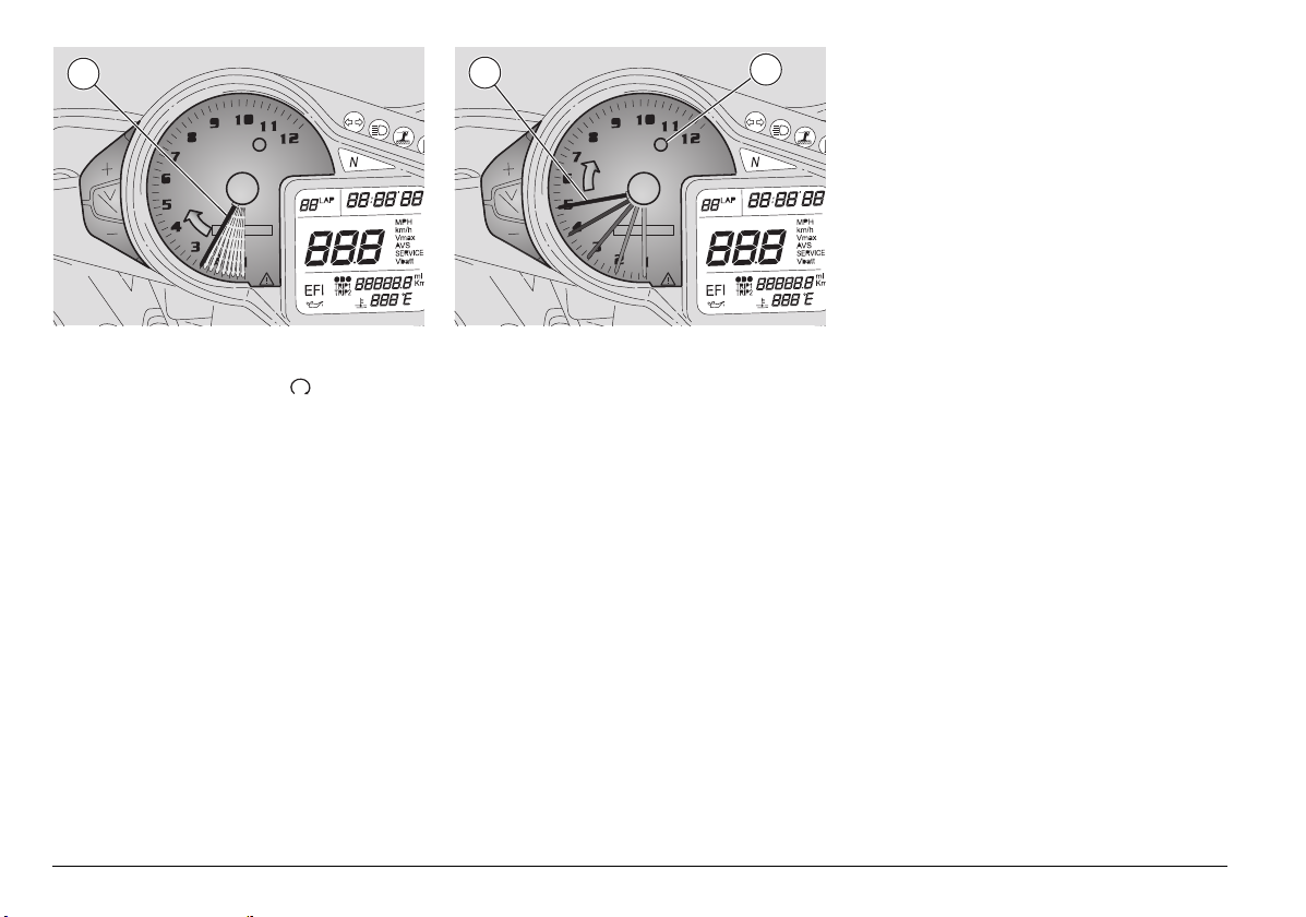
SETTING THE RED LINE THRESHOLD
(WITH ENGINE OFF ONLY)
When the maximum rpm set is
exceeded, the red line warning light
(red) (1) on the dashboard starts
blinking.
NOTE The red line
threshold, which operates the red line light,
can only be set with the engine off and the
odometer displayed. Setting range is 2,000
- 12,000 rpm.
Factory setting is 6,000 rpm.
To view red line threshold setting, hold
down the "Trip/V" button for at least 3
seconds. The rev counter pointer (2) will
point the corresponding rpm for three
seconds.
use and maintenance RSV 1000 R - RSV 1000 R FACTORY
23
Page 24
2
2
1
1
To set the red line threshold:
u Turn the ignition key to " ".
u Allow some time for the dashboard
check-up routine.
u Hold down the "Trip/V" button for at least
three seconds: the rev counter pointer
(2) will point the current red line setting.
u You have three seconds to change
setting as desired (as long as the rev
counter pointer (2) is pointing current red
line setting).
u Use the "+" button to change setting.
Press briefly to increase setting by 100
rpm. Hold down a little longer to increase
by 1000 rpm.
u After reaching full scale value (12,000
rpm), the pointer will go back to zero
automatically.
use and maintenance RSV 1000 R - RSV 1000 R FACTORY
24
u Three seconds after last pressing the "+"
button, the new red line threshold is
stored. This is confirmed by the red line
light (1) coming on for three seconds,
while the pointer (2) will go back to zero.
u If the engine is started during the setting
procedure, the last setting is retained.
The new threshold setting is also lost if
the battery is disconnected during the
setting procedure, and the last setting is
retained.
Page 25
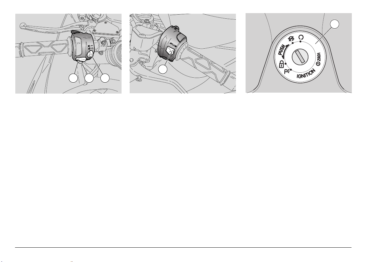
KEY CONTROLS
CONTROLS ON THE RIGHT SIDE
OF THE HANDLEBAR
NOTE The electric components will only
work when the ignition switch is in position
"".
1) ENGINE KILL SWITCH ( - )
CAUTION
Do not operate the engine kill switch
( - ) while riding.
This is a safety or emergency switch.
When it is in position " ", the engine
can be started. When set to position
" ", it will stop the engine.
1
2
CAUTION
Leaving the ignition switch in position
" " when the engine is stopped may
let the battery run flat.
After stopping the vehicle, stop the
engine and then turn the ignition switch
to position " ".
2) STARTER BUTTON ()
When pressed, the starter button "",
turns the engine over. See page 51
(STARTING) for starting procedure.
CONTROLS ON THE LEFT SIDE OF
THE HANDLEBAR
NOTE The electric components will only
work when the ignition switch is in position
"".
3) HORN BUTTON ()
Press it to operate the horn.
4) DIRECTION INDICATOR SWITCH
()
Move the switch to the left in order to
signal your intention to turn left; move
the switch to the right to signal a right
turn.
Press the switch to cancel the signal.
5) DIMMER SWITCH (- )
With the dimmer switch set to "",
the parking lights, the dashboard light
and the low beam are on.
Push the dimmer switch to position
"" to turn on the high beam.
Ensure that the dimmer switch is set to
"" before starting the engine.
use and maintenance RSV 1000 R - RSV 1000 R FACTORY
25
Page 26
3 4 5
1
6
6) HIGH BEAM FLASHER () / LAP
(multifunction) BUTTON
NOTE To set the functions, see page 18
(MULTIFUNCTION COMPUTER).
Press the button to flash the high beam
in an emergency. When pressed
together with the TRIP/V button, it turns
on the lap timer.
use and maintenance RSV 1000 R - RSV 1000 R FACTORY
26
NOTE Release the button to stop the
flasher.
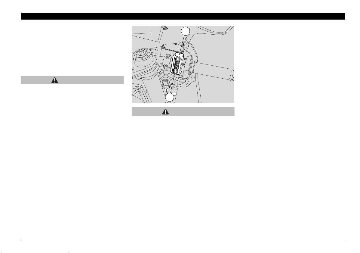
IGNITION SWITCH
The ignition switch (1) is positioned on the
steering head.
NOTE The key operates the ignition
switch/steering lock, the fuel filler cap lock
and the glove/tool kit compartment cover.
Two keys are delivered along with the
vehicle (one spare key).
NOTE Do not keep the spare key on the
vehicle.
NOTE Setting the ignition key to ""
automatically turns on the lights.
The lights will turn off when the ignition
switch is set to "".
Page 27
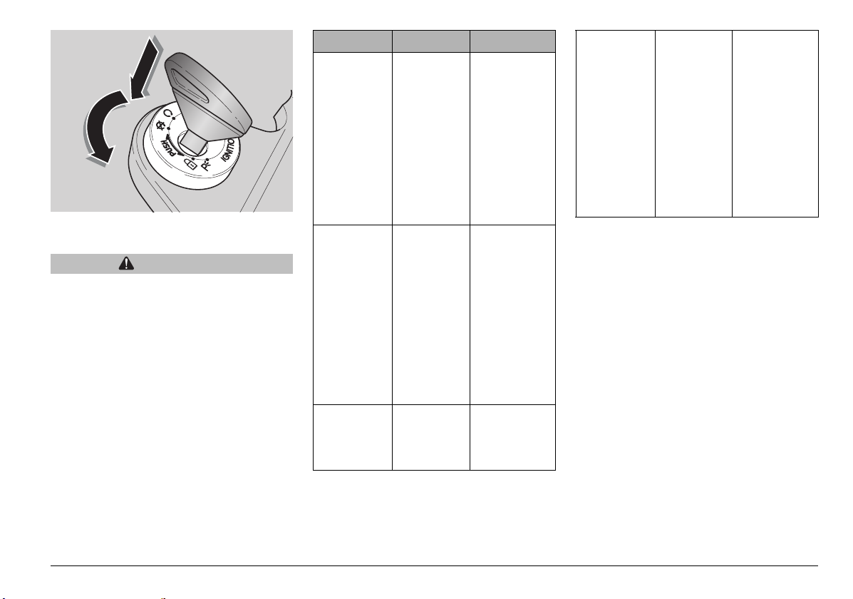
STEERING LOCK
WARNING
Never turn the key to position "" while
riding or you might lose control of the
vehicle.
OPERATION
To lock the steering:
u Turn the handlebar fully to the left.
u Turn the key to position "".
u Push in the key and turn it to "".
u Extract the key.
Position Function
The steering
is locked. It
is not
possible to
Steering
lock
start the
engine or
switch on
the lights
Neither the
engine nor
the lights
can be
operated.
The engine
and the
lights can be
operated.
Key removal
It is possible
to remove the
key.The
immobilizer
system is
activated
after the key
is removed.
(where
immobilizer
system is
fitted)
It is possible
to remove the
key. The
immobilizer
system is
activated
after the key
is removed.
(where
immobilizer
system is
fitted)
It is not
possible to
remove the
key.
The steering
is locked. It
is not
possible to
start the
engine.
The parking
lights of
headlight
and tail light
are turned
on.
It is possible
to remove the
key.
The
immobilizer
system is
activated
after the key
is removed.
(where
immobilizer
system is
fitted)
use and maintenance RSV 1000 R - RSV 1000 R FACTORY
27
Page 28
ACCESSORIES
3 2
1
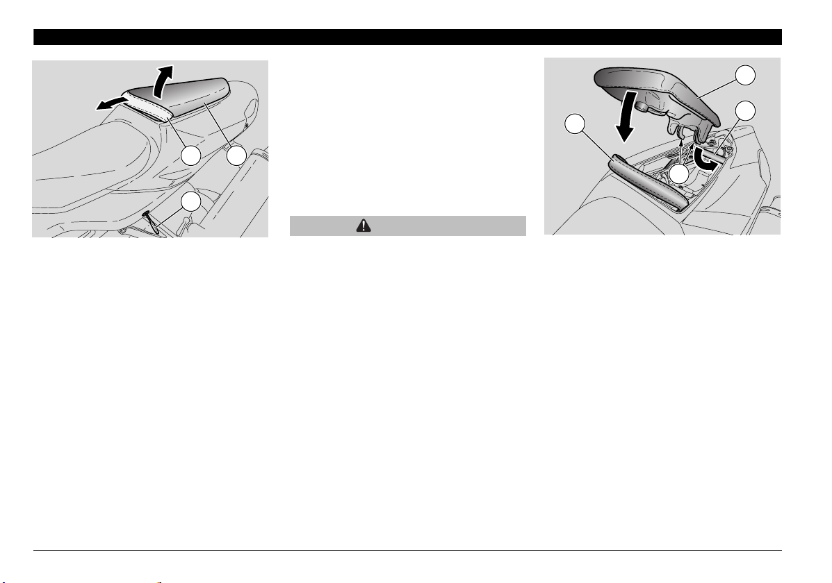
UNLOCKING/LOCKING THE
PASSENGER SEAT
u Place the vehicle on the stand, see page
58 (PLACING THE VEHICLE ON THE
STAND).
u Insert the key (1) into the seat lock.
u Release the passenger seat (2) from the
grab strap (3).
u Turn the key (1) anticlockwise.
u Raise the front end of the passenger
seat (2).
u Withdraw the passenger seat (2).
NOTE Before lowering and locking the
seat (2), make sure that you have not left
the key in the glove/tool kit compartment.
To lock the seat (2), proceed as follows:
u Slide the hooks (4) placed at the rear
end of the passenger seat underneath
the frame tube (5) of the rear subframe.
u Push the passenger grab strap (3)
forward and lower the front end of the
seat. Make sure to set the grab strap in
the correct position.
u Press down on the front end of the seat
so that the lock becomes engaged.
WARNING
Make sure the seat (2) is locked
securely before riding.
2
5
3
4
The tail of the vehicle accommodates a
convenient glove / tool kit compartment,
which is accessed by removing the
compartment cover.
NOTE The glove/tool kit compartment
cover can only be used when the
passenger seat (2) is removed and vice
versa.
To use the vehicle with the glove/tool kit
compartment cover it is necessary to
remove the passenger seat as previously
described.
See page 29 (UNLOCKING/LOCKING
THE GLOVE/TOOL KIT COMPARTMENT
COVER) for installation instructions.
use and maintenance RSV 1000 R - RSV 1000 R FACTORY
28
Page 29
2
2
1
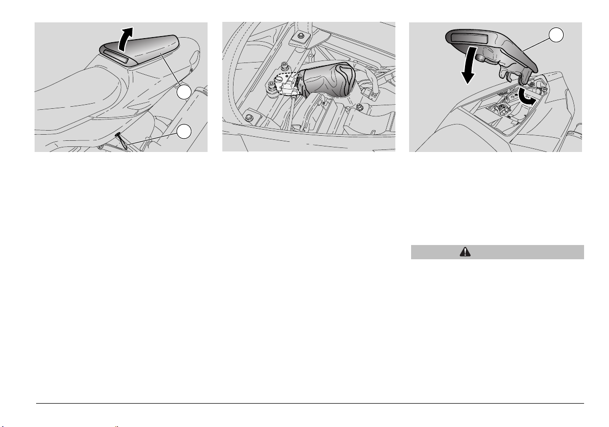
UNLOCKING/LOCKING THE
GLOVE/TOOL KIT COMPARTMENT
COVER
u Place the vehicle on the stand, see page
58 (PLACING THE VEHICLE ON THE
STAND).
u Insert the key (1) in the lock.
u Turn the key (1) anticlockwise, raise the
glove/tool kit compartment cover (2) and
ease it off in a forward motion.
The tail of the vehicle accommodates a
convenient glove / tool kit compartment,
which is accessed by removing the
compartment cover (2).
NOTE Before lowering and locking the
glove/tool kit compartment cover (2), make
sure that you have not left the key in the
glove/tool kit compartment.
To lock the glove/tool kit compartment
cover (2):
u Slide the lower front lugs underneath the
frame tube of the rear subframe.
u Position the glove/tool kit compartment
cover in its seat and press down until the
lock snaps shut.
WARNING
Before riding, make sure that the
glove/tool kit compartment cover (2) is
correctly locked.
use and maintenance RSV 1000 R - RSV 1000 R FACTORY
29
Page 30
3
2
5
9
4
6
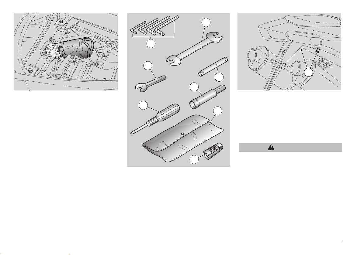
GLOVE/TOOL KIT COMPARTMENT
To reach the glove/tool kit
compartment, proceed as follows:
u Remove the passenger seat -see page
28 (UNLOCKING/LOCKING THE
PASSENGER SEAT) - or the glove/tool
kit compartment cover - see page 29
(UNLOCKING/LOCKING THE
GLOVE/TOOL KIT COMPARTMENT
COVER).
The tool kit (1) includes:
√ 3, 4, 5, 6 mm Allen spanners (2);
√ 11 - 13 mm double open-end spanner
(3);
√ 8 - 10 mm double socket spanner (4);
√ 17 mm open-end spanner (5);
√ 16 mm socket spanner for spark plug (6)
use and maintenance RSV 1000 R - RSV 1000 R FACTORY
30
7
8
9
√ double-ended (cross-headed/hexagon)
screwdriver (7);
√ tool box (8);
√ fuse puller (9)
Maximum load allowed: 1.5 kg.
LUGGAGE FIXING POINTS
The passenger seat can be used to carry
small luggage, which must be strapped
down securely to the suitable fixing points
(9).
Maximum load allowed: 9 kg.
WARNING
Carry small luggage only and make sure
it is fastened securely.
Page 31

SPECIAL TOOLS
Certain specific operations must be
performed using special tools, available
aprilia Official dealer:
from
Tool Operations
Pins (1) for the rear wheel
stand, see page 70
(FITTING THE PINS FOR
THE REAR WHEEL STAND
).
Rear wheel stand (2), see
page 70 (PLACING THE
VEHICLE ON THE REAR
WHEEL STAND )
Front wheel stand (3), see
page 71 (PLACING THE
VEHICLE ON THE FRONT
WHEEL STAND ).
Click clamp (4) installation
pliers, see page 63 (CLICK
CLAMPS).
To position the
vehicle on the
rear wheel stand.
Engine oil and
engine oil filter
change.Rear
wheel
disassembly.
Drive chain
adjustment.
Removal of the
lower fairing.
Front wheel
disassembly.
Click clamp
installation.
ACCESSORIES
- "R FACTORY" rear shock absorber, and
- adjustable steering damper,
which are fitted from standard to the RSV
1000 R FACTORY, can also be installed to
the RSV 1000 R (contact an
aprilia
Official dealer).
use and maintenance RSV 1000 R - RSV 1000 R FACTORY
31
Page 32

MAIN COMPONENTS
FUEL
WARNING
The fuel used to operate engines is
highly flammable and becomes
explosive under particular conditions.
Refuelling and engine service should
take place in a well-ventilated area with
the engine stopped. Do not smoke when
refuelling or in the proximity of sources
of fuel vapours. Avoid contact with
open flames, sources of sparks or any
other source which may ignite the fuel
or lead to explosion.
Take care not to spill fuel out of the
filler, or it may ignite when in contact
with hot engine parts.
In the event of accidental fuel spillage,
make sure the affected area is fully dry
before starting the engine. Fuel
expands from heat and when left under
direct sunlight. Never fill the fuel tank
up to the rim.
Tighten the filler cap securely after each
refuelling. Avoid contact with skin. Do
not inhale vapours. Do not swallow fuel.
Do not transfer fuel between different
containers.
DO NOT RELEASE FUEL INTO THE
ENVIRONMENT.
KEEP AWAY FROM CHILDREN.
Use only premium-grade unleaded fuel
with a minimum octane rating of 95 (RON)
and 85 (MON).
To refuel, proceed as follows:
u Raise the flap (1).
u Insert the key (2) into the filler cap lock
(3).
u Turn the key clockwise, pull and open
the fuel flap.
TANK CAPACITY (reserve included): 18
FUEL RESERVE: 4 b
b
CAUTION
Do not add any additives or other
substances to the fuel. If you use a
funnel ot other tool, make sure that they
are perfectly clean.
WARNING
Do not fill the tank up to the rim. Fuel
level must always remain below the
lower edge of the filler neck (see figure).
u Refuel.
After refuelling:
NOTE The cap can only be closed when
the key (2) is inserted.
u Press the cap with the key (2) inserted to
close.
WARNING
Make sure that the cap is properly
closed.
u Extract the key (2).
u Close the flap (1).
use and maintenance RSV 1000 R - RSV 1000 R FACTORY
32
Page 33

BRAKE FLUID - recommendations
NOTE This vehicle is fitted with front and
rear disk brakes. Each braking system is
operated by an independent hydraulic
circuit.
The information provided below applies to
both braking systems.
WARNING
Any sudden changes in play or
hardness in the brake lever are warning
signs of problems with the hydraulic
circuits.
If in doubt about the braking efficiency
of your bike or if you are not able to
perform routine checks, contact an
aprilia Official Dealer.
WARNING
Ensure that the brake disks and brake
linings have not become contaminated
with oil or grease. This is particularly
important after servicing or
inspections.
Make sure the brake lines are not
twisted or worn.
Prevent accidental ingress of water or
dust into the circuit. Wear latex gloves
when servicing the hydraulic circuit.
Brake fluid is an irritant. Avoid contact
with eyes or skin.
WARNING
In the event of accidental contact, wash
affected body parts thoroughly.
In the event of accidental contact with
eyes, contact an eye specialist or seek
medical advice.
KEEP AWAY FROM CHILDREN.
DO NOT RELEASE BRAKE FLUID INTO
THE ENVIRONMENT.
CAUTION
When handling brake fluid, take care
not to spill it onto plastic or paintfinished parts or they will damage.
use and maintenance RSV 1000 R - RSV 1000 R FACTORY
33
Page 34

DISK BRAKES
WARNING
The brakes are critical to your safety
and must always be kept in sleek
running order. Check the brakes before
each ride.
A dirty disk will soil the pads, leading to
loss of braking. Dirty pads must be
replaced, whereas a dirty brake disk
may be cleaned with a high-quality
degreasing product.
Have brake fluid changed at an
Official Dealer every two years.
Use the brake fluid specified in the
lubricant chart, see page 116
(LUBRICANT CHART).
aprilia
NOTE This vehicle is fitted with front and
rear disk brakes. Each braking system is
operated by an independent hydraulic
circuit.
use and maintenance RSV 1000 R - RSV 1000 R FACTORY
34
NOTE Halve service intervals when the
vehicle is used in rainy or dusty conditions,
on rough roads or for racing.
Have the brake disks checked by an
aprilia Official dealer after the first 1000
km (625 mi) and every 10000 km (6250 mi)
afterwards.
Before each ride, check brake fluid level in
both reservoirs - see page 35 (FRONT
BRAKE) and page 37 (REAR BRAKE),
and check the brake pads for wear - see
page92 (CHECKING THE BRAKE PADS
FOR WEAR).
The front brake is a twin-disk brake (one
disk on either side of the wheel).
The rear brake uses a single disk (fitted to
the right side of the wheel).
The information provided below applies to
both braking systems.
Brake fluid level decreases gradually as
the brake pads wear down.
The front brake fluid reservoir is mounted
near the front brake lever coupling.
The rear brake fluid reservoir is positioned
under the right lower fairing; to reach it,
remove the right lower fairing, see page 81
(REMOVING THE LOWER FAIRING).
Page 35

Have brake fluid changed every two years
by an
aprilia Official dealer.
WARNING
Do not ride if the braking system is
leaking.
FRONT BRAKE
CHECK
u Place the vehicle in vertical position,
keep the handlebar in the direction of
travel.
u Make sure that the fluid level in the
reservoir exceeds the "MIN" mark.
MIN= minimum level
MAX= maximum level
If level is below the "MIN" mark:
CAUTION
Brake fluid level decreases gradually as
the brake pads wear down.
u Check the brake disk and the brake pads
for wear, see page 92 (CHECKING THE
BRAKE PADS FOR WEAR).
If the pads and/or the disk are in good
condition, top up to correct level.
TOPPING UP
Read page 33 (BRAKE FLUID -
recommendations) carefully.
CAUTION
Danger: brake fluid could leak out.
Never operate the front brake lever
when the screws (1) have been
loosened or when the reservoir cover is
not in place.
u Unscrew the screws (1) of the brake fluid
reservoir (2) by means of a short, cross-
headed screwdriver.
use and maintenance RSV 1000 R - RSV 1000 R FACTORY
35
Page 36

WARNING
Avoid long exposure of brake fluid to
air.
Brake fluid is hygroscopic and will
absorb moisture from the air.
Keep the brake fluid reservoir open
JUST LONG ENOUGH to top up level.
u Raise and remove the cover (3) together
with the screws (1) and the gasket (4).
CAUTION
Do not rock the motorcycle from side to
side when topping up or brake fluid will
spill out.
Do not add any additives or other
products.
If you use a funnel or other tool, ensure
they are perfectly clean.
u Top up the reservoir (2) with brake fluid,
see page 116 (LUBRICANT CHART)
until exceeding "MIN" level mark.
CAUTION
While topping up, never pour too much
fluid.
Fill up to max. level only with new brake
pads.
If topped up to max. level with worn
pads, brake fluid will spill out when you
change the pads at a later time.
Check braking efficiency.
When the brake lever has exceeding
travel or if you notice a loss of braking,
contact an
braking system may need bleeding.
aprilia Official dealer. The
use and maintenance RSV 1000 R - RSV 1000 R FACTORY
36
Page 37

REAR BRAKE
CHECK
u Keep the vehicle upright, so that the fluid
in the reservoir (1) is parallel with the
plug (2).
u Look through the special slot in the right
fairing to check that fluid level in the
reservoir exceeds the "MIN" mark.
MIN= minimum level
MAX= maximum level
If level is below the "MIN" mark:
CAUTION
Brake fluid level decreases gradually as
the brake pads wear down.
u Check the brake disk and the brake pads
for wear, see page 92 (CHECKING THE
BRAKE PADS FOR WEAR).
2
4
3
1
If the pads and/or the disk are in good
condition, top up to correct level.
TOPPING UP
Read page 33 (BRAKE FLUID -
recommendations) carefully.
u Remove the right fairing, see page 81
(REMOVING THE SIDE FAIRINGS).
CAUTION
Danger: brake fluid could leak out.
Never operate the rear brake lever when
the reservoir cap is loose or has been
removed.
WARNING
Avoid long exposure of brake fluid to
air.
Brake fluid is hygroscopic and will
absorb moisture from the air.
Keep the brake fluid reservoir open
JUST LONG ENOUGH to top up level.
u Unscrew the screw (3) completely.
u Shift the complete reservoir (1)
moderately outwards.
u Unscrew and remove the cap (2).
CAUTION
Ensure the fluid in the reservoir is
parallel with the reservoir rim at all
times (in a horizontal position) when
topping up or brake fluid will spill out.
Do not add any additives or other
products.
If you use a funnel or other tool, ensure
they are perfectly clean.
u Remove the gasket (4).
u Top up the reservoir (1) with brake fluid,
see page 116 (LUBRICANT CHART)
until bringing level between the "MIN"
and "MAX" marks.
Always renew the brake pads before
topping up to "MAX" level.
CAUTION
Do not tilt reservoir (1) even if plug (2) is
tightened. This might let air in the
circuit and brake system would be
impaired.
use and maintenance RSV 1000 R - RSV 1000 R FACTORY
37
Page 38

CAUTION
Brake pad wear affects fluid level. If
topped up to "MAX" level with worn
pads, brake fluid will spill out when you
change the pads at a later time.
Check braking efficiency.
When the brake lever has exceeding
travel or if you notice a loss of braking,
contact an
braking system may need bleeding.
aprilia Official dealer. The
CLUTCH FLUID recommendations
NOTE This vehicle is fitted with a
hydraulically-controlled clutch.
CAUTION
Any sudden changes in play or
hardness in the clutch lever are warning
signs of problems with the hydraulic
circuit.
If in doubt about the proper operation of
the clutch or if you are not able to
perform routine checks, contact an
aprilia Official dealer.
CAUTION
Make sure the clutch hose is not twisted
or worn.
Prevent accidental ingress of water or
dust into the circuit. Wear latex gloves
when servicing the hydraulic circuit.
Clutch fluid is an irritant. Avoid contact
with eyes or skin.
In the event of accidental contact, wash
affected body parts thoroughly. In the
event of accidental contact with eyes,
contact an eye specialist or seek
medical advice.
DO NOT RELEASE CLUTCH FLUID
INTO THE ENVIRONMENT.
KEEP AWAY FROM CHILDREN.
1
When handling clutch fluid, take care
not to spill it onto plastic or paintfinished parts or they will damage.
Have clutch fluid changed every two
years by an
Use the clutch fluid specified in the
lubricant chart, see page 116
(LUBRICANT CHART).
The clutch fluid reservoir (1) is mounted
near the clutch lever coupling.
aprilia Official dealer.
use and maintenance RSV 1000 R - RSV 1000 R FACTORY
38
Page 39

NOTE Halve service intervals when the
vehicle is used in rainy or dusty conditions,
on rough roads or for racing.
Before each ride, check clutch fluid level in
the reservoir - see page 39 (CLUTCH).
Have clutch fluid changed every two years
by an aprilia Official dealer.
2
3
WARNING
Do not ride if the clutch hydraulic circuit
is leaking.
CLUTCH
NOTE Halve service intervals when the
vehicle is used in rainy or dusty conditions,
on rough roads or for racing.
Have the clutch checked by an
Official dealer every 10,000 km (6250 mi).
If the vehicle is used for racing:
have the clutch checked by an
Official dealer every 5000 km (3120 mi).
aprilia
aprilia
NOTE The engine is equipped with a
hydraulically-operated clutch, aided by the
patented PPC (Pneumatic Power Clutch)
system, which prevents rear wheel
bouncing under braking.
1
CHECK
u Place the vehicle in vertical position and
keep handlebar in the direction of travel.
u Make sure that the fluid level exceeds the
"MIN" mark.
MIN= minimum level
MAX= maximum level
u If fluid is below the "MIN" mark, top up to
correct level.
TOPPING UP
Read page 38 (CLUTCH FLUID -
recommendations) carefully.
CAUTION
Danger: clutch fluid could leak out. Never
operate the clutch lever when the reservoir
cap is loose or has been removed.
use and maintenance RSV 1000 R - RSV 1000 R FACTORY
39
Page 40

WARNING
Avoid long exposure of clutch fluid to
air.
Clutch fluid is hygroscopic and will
absorb moisture from the air.
Keep the clutch fluid reservoir open
JUST LONG ENOUGH to top up level.
u Unscrew and remove the plug (2).
CAUTION
Do not rock the motorcycle from side to
side when topping up or clutch fluid will
spill out.
Do not add any additives or other
products.
If you use a funnel or other tool, ensure
they are perfectly clean.
u Remove the gasket (3).
u Top up the reservoir (1) with clutch fluid,
see page 118 (LUBRICANT CHART)
until bringing level between the "MIN"
and "MAX" marks.
CAUTION
Never exceed the "MAX" level.
Check the clutch for proper operation.
When the clutch lever has exceeding
travel or if you notice a loss of
efficiency, contact an
dealer. The clutch hydraulic circuit may
need bleeding.
aprilia Official
COOLANT
CAUTION
Do not ride when coolant is below the
minimum level "LOW".
NOTE You will need to remove the right
side fairing in order to top up coolant level.
NOTE Halve service intervals when the
vehicle is used in rainy or dusty conditions,
on rough roads or for racing.
Check coolant level before each ride - see
page 42 (CHECKING AND TOPPING UP).
Have coolant changed every two years by
an
aprilia Official dealer.
use and maintenance RSV 1000 R - RSV 1000 R FACTORY
40
Page 41

1
WARNING
Coolant is toxic when ingested. Contact
with eyes or skin may cause irritation.
In the event of contact with eyes, rinse
repeatedly with abundant water and
seek medical advice. In the event of
ingestion, induce vomiting, rinse mouth
and throat with abundant water and
seek medical advice immediately.
KEEP AWAY FROM CHILDREN.
DO NOT RELEASE INTO THE
ENVIRONMENT.
Take care not to spill coolant onto hot
engine parts. It may ignite and produce
invisible flames.
Wear latex gloves when servicing.
CAUTION
Have coolant changed at an aprilia
Official dealer.
Coolant mixture is a 50% solution of water
and anti-freeze.
This is the ideal solution for most operating
temperatures and provides good corrosion
protection.
This solution is also suited to the warm
season, as the mixture is less prone to
evaporative loss and will reduce the need
for top-ups. In addition, less water
evaporation means fewer mineral salts
depositing in the radiator, which helps
preserve the efficiency of the cooling
system.
When temperature drops below zero
degrees centigrade, check the cooling
system frequently and add more antifreeze (up to 60% maximum) to the
solution.
Use distilled water in the coolant mixture.
Tap water will damage the engine.
WARNING
Do not remove the expansion tank plug
(1) when the engine is hot, since
coolant is very hot.
Contact with skin or clothes, may cause
severe scalding and/or damage.
use and maintenance RSV 1000 R - RSV 1000 R FACTORY
41
Page 42

1
2
CHECKING AND TOPPING UP
WARNING
Wait for the engine to cool down before
checking or topping up coolant level.
u Stop the engine and wait until it has
cooled down.
u Hold the vehicle upright, with both
wheels on the ground.
u Look through the slot (1) in the right
fairing and check that coolant level in the
expansion tank is between the "FULL"
and "LOW" marks.
FULL = maximum level
LOW = minimum level
use and maintenance RSV 1000 R - RSV 1000 R FACTORY
42
If not so:
u Remove the side fairing, see page 81
(REMOVING THE SIDE FAIRINGS).
u Unscrew and remove the filler cap (2).
WARNING
Coolant is toxic when ingested. Contact
with eyes or skin may cause irritation.
Do not put your fingers or any other
object into the filler opening in order to
ensure that there is coolant.
CAUTION
Do not add any additives or other
products.
If you use a funnel or other tool, ensure
they are perfectly clean.
u Top up with coolant, see page 116
(LUBRICANT CHART) up to just below
the "FULL" mark. Never top up beyond the
"FULL" level mark or coolant will leak out
when the engine is running.
u Refit the filler cap (2).
CAUTION
If coolant level drops too quickly or the
tank is empty, check the cooling circuit
for leaks. Have the leak repaired at an
aprilia Official dealer.
Page 43

TYRES
This vehicle is fitted with tubeless tyres.
NOTE Halve service intervals when the
vehicle is used in rainy or dusty conditions,
on rough roads or for racing.
WARNING
Check the tyre condition and inflation
pressure at room temperature every two
weeks.
Check the tyre condition and inflation
pressure at room temperature after the
first 1000 km (625 mi) and every two
weeks afterwards, see page 112
(TECHNICAL DATA).
Checking pressure on hot tyres will
result in inaccurate measurement.
Take care to check tyre pressures
before and after a long journey.
An overinflated tyre will provide a harsh
ride, reduce riding comfort and stability
when cornering.
An underinflated tyre will extend the
contact patch to include a larger portion
of the tyre wall (1). When this is the
case, the tyre may slip on or become
separated from the rim, leading to loss
of control.
The tyre may even come off the rim
under hard braking.
Lastly, the vehicle may skid in a bend.
WARNING
Inspect tread surface and check for
wear. Badly worn tyres adversely affect
road holding and handling.
Some of the tyre types approved for this
vehicle are fitted with wear indicators.
There are various types of wear
indicators.
Enquire about the correct wear
inspection procedure with your
supplier.
Visually inspect the tyres for wear and
have them changed when worn.
A tyre that becomes punctured in the
tread area should be changed when the
puncture is larger than 5 mm.
The wheel must be balanced after each
tyre repair.
WARNING
Use tyres of the specified type and
model recommended by the
manufacturer, see page 112
(TECHNICAL DATA). Using other than
specified tyres may adversely affect
handling.
Never use tube tyres on tubeless tyre
rims, or vice versa.
Always check that the caps are in place
on the valves (2), or the tyres may
deflate suddenly.
Tyre replacement and repair, as well as
wheel servicing and balancing are
delicate operations. They should be
carried out using adequate tools and
are best left to experienced mechanics.
Have your tyres and wheels serviced at
an
aprilia Official dealer or a
specialised tyre repairer.
New tyres may be coated with an oily
film. Drive carefully until covering
several kilometres. Never apply nonspecific products to the tyres. Old tyres
may not ensure full grip due to material
ageing - even when they are still within
the wear limit - and must be replaced.
use and maintenance RSV 1000 R - RSV 1000 R FACTORY
43
Page 44

MINIMUM RECOMMENDED TREAD
DEPTH (3):
front and rear 2 mm ( 3 mm) and in any
case not less than prescribed by the
regulations in force in the country where
the vehicle is used.
ENGINE OIL
WARNING
Prolonged or repeated contact with oil
may cause severe skin damage.
Wash your hands thoroughly after
handling oil.
KEEP AWAY FROM CHILDREN.
DO NOT RELEASE INTO THE
ENVIRONMENT.
Place oil in a sealed container and
dispose of it through a waste oil
reclamation firm or through your usual
supplier.
Wear latex gloves during servicing.
CAUTION
If the warning light " " comes on and
the symbol "" appears on the display
during normal engine operation, it
means that engine oil pressure in the
circuit is too low.
When this is the case, check engine oil
level, see page 64 (CHECKING AND
TOPPING UP ENGINE OIL LEVEL). If
engine oil level is not correct, stop the
engine immediately and contact an
aprilia Official dealer.
CAUTION
Handle carefully.
Do not spill oil!
Avoid smearing any vehicle
components, the area in which you are
working and the surrounding area.
Remove any trace of oil.
In case of leakage or malfunctions,
contact an aprilia Official dealer.
Check engine oil level at regular intervals,
see page 64 (CHECKING AND TOPPING
UP ENGINE OIL LEVEL).
See page 61 (PERIODIC MAINTENANCE
CHART) and page 65 (CHANGING
ENGINE OIL AND THE ENGINE OIL
FILTER) for oil change instructions.
NOTE Use high-quality 15W - 50 oil, see
page 116 (LUBRICANT CHART).
use and maintenance RSV 1000 R - RSV 1000 R FACTORY
44
Page 45

56
3
2
1
ADJUSTING THE FRONT BRAKE
LEVER AND THE CLUTCH LEVER
The grab distance of the lever (1) (distance
from the grip (2)) can be adjusted by
rotating the adjuster (3).
The MAX and MIN click settings give a
grab distance of 126 and 83 mm,
respectively.
Push the lever (1) forward and rotate
the adjuster (3) until setting the lever (1)
at the desired distance.
4
ADJUSTING REAR BRAKE LEVER
CLEARANCE
Brake lever position is determined based
on ergonomic principles at the factory.
If necessary, it is possible to adjust brake
lever clearance:
u Slacken the lock nut (4).
u Unscrew the master cylinder actuating
rod (5) to ensure a minimum clearance
of 0.5 - 1 mm between the rod and the
piston.
CAUTION
Make sure that the lever (6) has a
certain amount of free play, or the brake
will remain applied leading to early wear
of braking elements.
Free play of lever (6): 4 mm (measured
at the lever end).
u Lock the master cylinder actuating rod
(5) by means of the lock nut (4).
CAUTION
After the adjustment, make sure that the
wheel rotates freely with the brake
released.
Check braking efficiency.
If necessary, contact your
Official dealer.
use and maintenance RSV 1000 R - RSV 1000 R FACTORY
aprilia
45
Page 46

CAUTION
If the gear shift lever needs further
adjustment, contact an
dealer.
MUFFLER/EXHAUST SILENCER
aprilia Official
Check the muffler/exhaust silencer and the
silencer pipes for rust or holes. Ensure that
the exhaust system works correctly.
If the exhaust system noise increases,
contact an
immediately.
aprilia Official dealer
ADJUSTING THE REAR BRAKE
LEVER AND THE GEAR SHIFT
LEVER
The position of the control levers is
determined based on ergonomic principles
at the factory.
If necessary, it is possible to adjust the
position of the levers.
u Place the vehicle on the stand, see page
58 (PLACING THE VEHICLE ON THE
STAND).
u Partially unscrew the screw (1).
u Rotate the eccentric (2) until finding the
optimal position for the pedal (3).
u Tighten the screw (1) and make sure that
the eccentric retains its position.
WARNING
Tampering with the noise control
system is prohibited.
Owners are warned that the law may
prohibit:
-The removal or disconnection of any
device or element of design incorporated
into any new vehicle to limit the noise
emissions before its sale or delivery to
the final purchaser or while it is in use
except if carried out for maintenance,
repair or replacement purposes.
-The use of the vehicle after the removal or
disconnection of this device or element of
design.
WARNING
Both exhaust silencers are equipped
with catalytic converter and become
very hot to the touch. Be careful!
Danger of burns!
use and maintenance RSV 1000 R - RSV 1000 R FACTORY
46
Page 47

INSTRUCTIONS FOR USE
`
GETTING ON AND OFF THE
VEHICLE
The instructions below must be followed
with the maximum care in order to avoid
injury to persons and damage to property
and to the vehicle, caused by the rider or
passenger falling from the vehicle and/or
the vehicle falling or overturning.
WARNING
Risk of falling and overturning.
Proceed with care.
When getting on and off the vehicle, make
sure nothing can impair your movements.
Also, your hands should be free (replace
any objects, such as your helmet, gloves or
dangling glasses before mounting or
dismounting).
Always mount and dismount from the left
side with the vehicle on the side stand.
CAUTION
However, do not apply you full weight
or that of the passenger to the side
stand.
The stand has been designed to support
the weight of the vehicle and a minimum
load, without the rider and the passenger.
The purpose of placing the vehicle on the
side stand before mounting is to keep the
vehicle from falling or overturning. This
does not mean that the side stand should
be used to support the weight of rider and
passenger.
While getting on and off, the weight of the
vehicle may make you lose balance, and
the vehicle may fall or overturn.
NOTE The rider must always mount
before the passenger and dismount after
the passenger. It is the rider's responsibility
to keep the vehicle balanced while the
passenger gets on and off.
use and maintenance RSV 1000 R - RSV 1000 R FACTORY
47
Page 48

The passenger must move carefully when
getting on and off the vehicle, to avoid
upsetting the balance of vehicle and rider.
NOTE It is the rider's responsibility to
instruct the passenger on how to safely get
on and off the vehicle.
The vehicle is equipped with special
passenger footrests to make it easier to get
on and off the vehicle. The passenger must
always use the left footrest to get on and
off the vehicle.
Never get off or try to get off the vehicle by
jumping or stretching your leg and putting
your foot on the ground. This would
compromise the stability and balance of
the vehicle.
NOTE Any bags or objects strapped to
the rear of the vehicle can impair your
movements while getting on and off.
When mounting or dismounting, swing
your right leg over the vehicle in a
controlled movement. Do not hit the rear
end (tail or luggage) or you will upset
vehicle balance.
GETTING ON THE VEHICLE
u Grasp the handlebar correctly and get on
the vehicle without loading your weight
onto the side stand.
NOTE If you cannot touch both feet on
the ground, set the right foot firmly on the
ground (if you should lose your balance,
the side stand on the left side of the vehicle
will keep you from falling over on that side)
and keep ready to place your left foot on
the ground.
u Push the vehicle upright and place both
feet on the ground. Keep the vehicle
balanced.
NOTE Do not fold out the passenger
footrest or attempt to do so while sitting
astride the vehicle, or you might lose
balance.
u Instruct the passenger to fold out both
passenger footrests.
u Explain to the passenger how to safely
get on the vehicle.
u Pull up the side stand using your left foot.
Make sure it is fully up.
GETTING OFF THE VEHICLE
u Choose the parking area, see page 57
(PARKING).
u Stop the vehicle, see page 57 (STOPPING).
WARNING
Make sure that the parking surface is
free from obstacles. Park on firm and
level ground.
u Push down on the side stand lever with
the left heel until the side stand is fully
down.
NOTE If you cannot touch both feet on
the ground, set the right foot firmly on the
ground (if you should lose your balance,
the side stand on the left side of the vehicle
will keep you from falling over on that side)
and keep ready to place your left foot on
the ground.
u Place both feet on the ground and keep
the vehicle upright and balanced.
u Explain to the passenger how to safely
get off the vehicle.
CAUTION
Risk of falling and overturning.
Make sure that the passenger has
dismounted.
u Do not place your weight on the side
stand.
u Lean the vehicle until the stand touches
the ground.
u Grasp the handlebar correctly and get off
the vehicle.
u Rotate the handlebar fully to the left.
u Fold the passenger footrests.
CAUTION
Make sure that the vehicle is stable.
use and maintenance RSV 1000 R - RSV 1000 R FACTORY
48
Page 49

N
2
1
PRE-RIDE CHECKS
WARNING
Check the vehicle before each ride to
ensure safe riding. (See the PRE-RIDE
CHECKS CHART). Failure to do so may
lead to severe injury or vehicle damage.
If you have any doubts on the operation of
the vehicle controls or believe that any
vehicle components might be faulty, do not
hesitate to contact an
dealer.
A quick check is done in no time, but does
wonders for your safety.
aprilia Official
NOTE This vehicle provides real-time
diagnostics of failures stored into the
Engine Control Unit.
Each time the ignition key is set to "", the
wording "Efi" (1) appears on the right side
of the multifunction display for
approximately three seconds.
CAUTION
If the wording "Efi" (1) is displayed
during normal engine operation, it
means that the Engine Control Unit has
detected an anomaly.
In most cases, the engine will keep
running, although giving less
performance. At any rate, contact an
aprilia Official dealer immediately.
CAUTION
After covering the first 1000 km (625 mi)
and every 10,000 km (6250 mi)
afterwards, the "SERVICE" warning (2)
appears on the right display.
When you see this warning, contact an
aprilia Official dealer to have the
vehicle serviced and inspected
according to the periodic maintenance
chart, see page 61 (PERIODIC
MAINTENANCE CHART). To cancel the
"SERVICE" warning, turn the key to ON
while holding down the "+" and "-"
buttons at the same time for at least 15
seconds.
use and maintenance RSV 1000 R - RSV 1000 R FACTORY
49
Page 50

PRE-RIDE CHECKS CHART
Part Action Page
Check for proper operation. Check brake lever free play and brake fluid level. Check for leaks
Front and rear disk brakes
Throttle
Engine oil Check and top up as required. 44, 65
Wheels/tyres
Brake levers Make sure they move smoothly. Lubricate the joints and adjust travel, if necessary 45
Clutch
Steering Steering should rotate smoothly and evenly. There should be no play or looseness.
Side stand
and brake pad wear.
Top up brake fluid level, if necessary.
Ensure that it turns smoothly. The throttle should open and close fully at all positions of the
steering. Adjust and/or lubricate, if necessary.
Check tyre surface, inflation pressure. Check for wear or damage. Remove any foreign objects
lodged in the tread.
Check for proper operation, check clutch lever free play, clutch fluid level and check for
leaks.Top up clutch fluid, if necessary. The clutch should not jerk or slip
The stand should operate smoothly and snap back in the rest position in a smooth motion.
Spring action must be enough to fold it fully up. Lubricate joints and connections, if necessary.
Check stand switch for proper operation.
.
33, 34, 35,
37, 93
94
43
38, 39
√
96, 102
Fasteners Make sure the fasteners are properly tightened. Adjust or tighten as required. √
Drive chain Check slack.
78, 80
Check fuel level and refuel if low.
Fuel tank
Check for leaks in the fuel system.
32, 81
Make sure the filler cap is tightened securely.
Coolant Coolant level in the expansion tank must be between the "FULL" and "LOW" marks.
Engine kill switch
( - )
Check for proper operation. 25
40, 44
Lights, warning lights, horn,
rear brake light switches and
Check horn and indicators for proper operation. Change bulbs or fix a failure, if necessary.
98 - 109
electrical devices
use and maintenance RSV 1000 R - RSV 1000 R FACTORY
50
Page 51

3
1
2
STARTING
WARNING
The vehicle's engine delivers
considerable power. Familiarise with
the vehicle gradually and use the
greatest care.
Do not place any objects on the inside
of the front fairing (between the
handlebar and the dashboard), or they
might hinder handlebar rotation and
hide the dashboard from view.
NOTE Before starting the engine,
carefully read section "Safe Riding", see
page 5 (SAFE RIDING).
4
45
4
N
6
WARNING
Exhaust emissions contain carbon
oxide, which is a poisonous gas and
extremely harmful if inhaled.
Never operate the engine indoor. Make
sure the area is well ventilated before
starting the engine.
Failure to heed these warnings may
lead to loss of conscience or even
death.
NOTE With the side stand down, the
engine can only be started if the gearbox is
in neutral. If you try to engage a gear with
the stand down, the engine will stop.
With the side stand up, the engine can be
started either in neutral or with a gear
engaged while keeping the clutch lever
pulled in.
u Sit astride the vehicle, see page 47
(GETTING ON AND OFF THE VEHICLE).
u Make sure the stand is fully up.
u Make sure the dimmer switch (1) is in
position "".
u Set the engine kill switch (2) to "".
u Turn the key (3) to set the ignition switch
to position "".
When you turn the key:
- All digits of the multifunction display come
on for 3 seconds.
- All dashboard warning lights (4) and the
backlighting come on for 3 seconds.
- The odometer pointer (5) points the last
red line threshold setting for 3 seconds
and then returns to idle rpm.
- During normal operation, all instruments
will give the current reading.
CAUTION
When the low fuel light "" (6) comes
on, refuel as soon as possible. See
page 32 (FUEL).
use and maintenance RSV 1000 R - RSV 1000 R FACTORY
51
Page 52

u The vehicle is equipped with a cold start
9
feature controlled by the ECU which
operates automatically when starting the
engine from cold.
8
7
NOTE The units of measurement of
speedometer (km or mi) and coolant
temperature (°C or °F), the red line
threshold, clock functions and lap timer are
user-selectable. See page 18
(MULTIFUNCTION COMPUTER).
WARNING
The red line threshold is set at 6000 rpm
at the factory. Increase the threshold
gradually as you become familiar with
your vehicle.
During running-in, never exceed the
recommended rpm, see page 56
(RUNNING-IN).
u Lock at least one wheel, by pulling a
brake lever.
u Pull the clutch lever (7) fully in and select
neutral using the gear lever (8) [green
light "" (9) on].
CAUTION
Do not press the starter button "" for
more than fifteen seconds at a time or it
will draw too much current from the
battery.
If the engine does not start within
fifteen seconds, wait ten seconds and
then press the button "" again.
u Press the starter button "" (10) - do not
open the throttle yet - and release the
button as soon as the engine starts.
CAUTION
Avoid pressing the starter button ""
(10) with the engine running or you will
damage the starter motor.
After the engine has started, the engine
oil pressure light "" (11) must go out.
If the oil light stays on or comes on
during normal operation, it means that
oil pressure in the circuit is too low.
When this is the case, stop the engine
immediately and contact an
Official dealer.
u Keep at least one brake lever pulled and
do not accelerate before moving off.
aprilia
11
10
CAUTION
Do not move off abruptly after starting
the engine from cold.
Ride at low speed until covering several
kilometres. This will allow the engine to
warm up and reduce polluting
emissions and fuel consumption.
CAUTION
If the wording "EFI" appears on the
multifunction display during normal
engine operation, it means that the
Engine Control Unit has detected an
anomaly.
In most cases, the engine will keep
running although with less than ideal
performance. Contact an
dealer immediately.
aprilia Official
use and maintenance RSV 1000 R - RSV 1000 R FACTORY
52
Page 53

1
MOVING OFF - RIDING
WARNING
The vehicle's engine delivers
considerable power. Familiarise with
the vehicle gradually and use the
greatest care.
Do not place any objects on the inside
of the front fairing (between the
handlebar and the dashboard), or they
might hinder handlebar rotation and
hide the dashboard from view.
NOTE Before moving off, carefully read
section "Safe Riding", see page 5 (SAFE
RIDING).
CAUTION
If the low fuel light "" (1) on the
dashboard comes on while the vehicle is
running, it means that you still have 4.5 ±1l
of fuel in the tank. Refuel as soon as
possible, see page 34 (FUEL).
WARNING
If you are riding solo, make sure that the
passenger footrests are folded. While
driving, keep your hands on the grips
and your feet on the footrests.
NEVER DRIVE IN ANY POSITION
OTHER THAN THOSE INDICATED.
WARNING
If you are carrying a passenger, instruct
him/her on the basic safety rules of
pillion riding.
Ensure that the stand is fully up before
moving off.
Moving off:
u Start the engine. See page 51
(STARTING).
u Adjust the rear-view mirrors.
CAUTION
With the vehicle stopped, try to
familiarise with the use of the mirrors.
Convex mirrors provide a larger view,
but any objects seen in these mirrors
seem farther than they really are. It may
take some time to learn to judge the
distance of traffic behind accurately.
u With the throttle twistgrip (2) released
(Pos. A), let engine idle and pull the
clutch lever (3) fully in.
u Engage the first gear, by pushing the
gear lever (4) downwards.
u Release the brake lever (you should
have pulled it when starting the engine).
use and maintenance RSV 1000 R - RSV 1000 R FACTORY
53
Page 54

3
2
WARNING
Release the clutch lever smoothly, or
you may stall the engine or cause the
vehicle to jerk forwards.
Open the throttle slowly and gradually
when releasing the clutch lever. Abrupt
acceleration will cause the clutch to slip
(if released slowly) or will lead to a
wheelie, if the clutch is released
abruptly.
u Slowly release the clutch lever (3) while
opening the throttle slightly (2) (Pos.B).
The vehicle will start moving.
u Ride at low speed until covering several
kilometres. This will allow the engine to
warm up.
CAUTION
Never exceed the recommended rpm,
see page 56 (RUNNING-IN).
u Increase speed by gradually opening the
throttle (2) (Pos.B), without exceeding
the recommended rpm, see page 56
(RUNNING-IN).
To engage the second gear:
CAUTION
Proceed quickly.
Never let the engine run at too low rpm.
u Release the throttle twistgrip (2) (Pos.A),
pull the clutch lever (3) and lift the gear
shift lever (4). Release the clutch lever
(3) and accelerate.
u Repeat the last two operations and shift
up.
CAUTION
If the engine oil pressure LED "" (5)
comes on during normal engine
operation, it means that engine oil
pressure in the circuit is too low.
If so, stop the engine immediately and
contact an
Downshifting is normally required in the
following conditions:
u When riding downhill or when braking, in
order to use engine braking for improved
braking efficiency.
u When riding uphill, if the gear engaged is
too high for your speed and the engine
rpm decreases.
aprilia Official dealer.
CAUTION
When shifting down, always select the
next lower gear or you will cause the
engine to race (exceed maximum rpm).
Before and during the downshifting,
release the throttle grip and decelerate,
in order to avoid racing the engine.
use and maintenance RSV 1000 R - RSV 1000 R FACTORY
54
Page 55

To shift down, proceed as follows:
u Release the throttle grip (2) (Pos.A).
u If necessary, apply both brakes lightly to
slow down the vehicle.
u Pull the clutch lever (3) and lower the
gear shift lever (4) to shift down.
u Release the brake levers if you have
pulled them.
u Release the clutch lever and accelerate
moderately.
CAUTION
If the coolant temperature readout of
the multifunction display is between
115°C (239°F) and 135°C (275°F) - see
page 18 (MULTIFUNCTION
COMPUTER), stop the vehicle and let
the engine run at 3000 rpm for
approximately two minutes to keep
coolant circulating in the system. After
two minutes, set the engine kill switch
to "" and check coolant level, see
page 40 (COOLANT).
If coolant temperature readout is still
flashing after you have checked level,
contact an
aprilia Official dealer.
Do not set the ignition switch to "", as
this would switch off the cooling fans
regardless of coolant temperature and
temperature would keep rising.
If the wording "EFI" appears on the right
multifunction display during normal
engine operation, it means that the
Engine Control Unit has detected an
anomaly.
In most cases, the engine will keep
running, although performance may be
somewhat reduced. Contact an aprilia
Official dealer immediately.
When the vehicle is at standstill with the
engine running, do not keep the clutch
lever pulled and a gear engaged for
long periods, or the clutch will overheat.
WARNING
Do not open and close the throttle
repeatedly and continuously, or you
may lose control of the vehicle. When
you need to brake, use both brakes to
slow down gradually and adjust the
pressure on the brakes as required.
Using one brake only reduces braking
force significantly and may lock a wheel
resulting in loss of grip.
To stop while riding uphill, close the
throttle and simply use the brakes to
keep the vehicle steady. Using the
engine to keep the vehicle steady may
result in the clutch overheating.
When approaching a bend, slow down
or brake in good time. Take the bend at
moderate, steady speed or accelerate
slightly. Late braking may put the
vehicle into a skid.
Use the brakes sparingly when riding
downhill, or the brake lining may
overheat and impair braking efficiency.
Use engine braking and apply both
brakes intermittently.
Never ride downhill with the engine off.
In low visibility, switch on the low beam
even during the day, in order to make
your vehicle more visible. When riding
on wet or slippery surfaces (such as
snow, ice, mud), slow down, avoid
harsh braking and do not swerve
suddenly to avoid skidding.
use and maintenance RSV 1000 R - RSV 1000 R FACTORY
55
Page 56

WARNING
Watch for skid hazards and changes in
the road surface.
Uneven road surfaces, rails, inspection
covers, painted signals, construction
site metal covers become slippery in
rainy weather and must be negotiated
carefully, smoothly and keeping the
vehicle upright.
Always signal your intention to change
lanes or direction in good time using
the direction indicators. Avoid sudden
manoeuvres. Switch off the direction
indicators immediately after changing
direction. Be very careful when
overtaking or being overtaken.
When it rains, large vehicles lift surface
water, which affects visibility. In
addition, the slip stream may make you
lose control of the vehicle.
RUNNING-IN
Proper engine running-in is essential to
preserving engine life and performance
over time. Twisty roads and gradients are
ideal to break in engine, suspension and
brakes effectively.
Vary speed frequently during running-in.
This will vary the amount of loading you will
be putting on engine parts so as to allow
them to cool down.
While it is important to place a certain
amount of stress on engine components
during the running-in period, take care not
to exceed.
NOTE Top performance is only obtained
after covering the first 1500 km (937 mi).
Observe the following instructions:
u Do not flip the throttle open abruptly
when the engine is running at low speed,
both during and after the running-in
period.
u Apply the brakes gently and avoid hard,
prolonged braking until covering the first
100 km (62 mi). This will allow the brake
pad lining to break in properly rubbing on
the brake disks.
u During the first 1000 km (625 mi) never
exceed 6000 rpm.
WARNING
After the first 1000 km (625 mi), have an
aprilia Official dealer carry out the
"Post running-in" checks specified in
the periodic maintenance chart, see
page 61 (PERIODIC MAINTENANCE
CHART). Failure to perform these
checks may lead to injury to yourself or
other people and/or vehicle damage.
u After the first 1000 km (625 mi) and until
covering 1500 km (937 mi), drive more
briskly, varying speed and using
maximum acceleration for just a few
seconds, in order to ensure better
coupling of the components; never
exceed 7500 rpm (see table).
u After the first 1500 km (937 mi), you can
expect higher performance from your
engine. However, never exceed the
maximum rpm allowed (11,000 rpm).
Recommended maximum engine rpm
Distance covered, km
(mi)
0 √ 1000 (0 √ 625) 6000
1000 √ 1500 (625 √ 937) 7500
over 1500 (937) 11000
rpm
use and maintenance RSV 1000 R - RSV 1000 R FACTORY
56
Page 57

2
1
STOPPING
WARNING
If possible, avoid stopping abruptly or
slowing down suddenly. Brake
progressively and in good time.
u Release the throttle twistgrip (1) (pos.
A), apply the brakes gradually and shift
down to reduce speed, see page 53
(MOVING OFF - RIDING).
When you have slowed down, before
stopping the vehicle:
u Pull the clutch lever (2) to avoid stalling
the engine.
When the vehicle is at standstill:
u Place the gear lever in neutral (green
warning light "" on).
u Release the clutch lever (2).
u When stopping for a short time, keep at
least one brake on.
43 5
PARKING
Select a suitable parking area, observing
the road signs and the indications given
below.
WARNING
Park the vehicle on firm and level ground
to prevent it falling over.
Do not lean the vehicle against walls and
do not lay it down on the ground.
Make sure that the vehicle, and in
particular hot vehicle components, may
not put the safety of persons and children
at risk. Do not leave the vehicle
unattended with the engine running or
with the key inserted into the ignition
switch.
Stay away from the cooling fans even
when they are not operating. They might
switch on unexpectedly and your clothing
or hair might be caught in the fans.
WARNING
Leaning the vehicle exceedingly or
letting it fall over may lead to fuel
leakage.
The fuel used to operate internal
combustion engines is highly
flammable and becomes explosive
under particular conditions.
CAUTION
Do not place your full weight or that of
the passenger on the side stand.
To park the vehicle:
u Choose a suitable parking area.
u Stop the vehicle, see page 57
(STOPPING).
u Set the engine kill switch (3) to position
" - ".
u Turn the key (4) to set the ignition switch
(5) to position "".
WARNING
When getting on or off the vehicle,
follow the instructions provided at page
47 (GETTING ON AND OFF THE
VEHICLE).
u Following the indications, wait until the
passenger has dismounted before getting
off the vehicle.
u Lock the steering, see page 27 (STEERING
LOCK) and extract the key (4).
WARNING
Make sure that the vehicle is stable
use and maintenance RSV 1000 R - RSV 1000 R FACTORY
57
Page 58

PLACING THE VEHICLE ON THE
STAND
SIDE STAND
To place the vehicle on the side stand
while sitting astride the vehicle, see page
47 (GETTING ON AND OFF THE
VEHICLE). If you have lifted the stand,
say, to move the vehicle, place the vehicle
on the stand as follows:
1
2
3
WARNING
Make sure that the parking ground is
free from obstacles, firm and level.
u Choose a suitable parking area, see
page 57 (PARKING).
u Grasp the left grip (1) and place your
right hand on the rear upper part of the
vehicle (2).
u Push on the side stand with your right
foot and lower it completely (3).
u Lean the vehicle until the stand is
touching the ground.
u Turn the handlebar fully to the left.
SUGGESTIONS TO PREVENT
THEFT
CAUTION
Do not use any “brake lock” devices.
Failure to heed this warning can
seriously damage the braking system
and lead to an accident thus provoking
serious injuries or death.
NEVER leave the ignition key in the switch
and always use the steering lock. Park the
vehicle in a safe place, possibly in a
garage or an area protected by security. If
possible, use an additional anti-theft
device. Make sure to have all the
necessary documents and the Excise Duty
stamp. Write down your personal data and
telephone number in this page. This will
identify you as the owner in the event the
vehicle is stolen and then recovered.
SURNAME: ...............................................
NAME: .......................................................
ADDRESS: ................................................
use and maintenance RSV 1000 R - RSV 1000 R FACTORY
58
WARNING
Make sure that the vehicle is stable.
...................................................................
TELEPHONE NO.: ....................................
NOTE In most cases, stolen vehicles
are identified through the data written on
the Owner's Manual.
Page 59

IMMOBILIZER (if fitted)
The vehicle is fitted with an immobilizer
anti-theft system by that
is automatically activated each time the
ignition key is removed from the switch.
Store the spare key in a safe place.
Immobilizer system keys cannot be
duplicated. If both keys are lost, you will
have to have a number of vehicle
components replaced (rather than just the
key-operated locks).
Embedded in the key grip is a transponder,
an electronic device that modulates the
radiofrequency signal emitted by a special
antenna built into the switch when the key
is turned to on. The modulated signal acts
as a "password" that tells the control unit
whether an authorised key is being used to
start the engine.
NOTE The Immobilizer system supports
up to four enabled keys. New keys can
only be enabled at your Official Dealer,
who has the master key available.
The programming procedure wipes off all
existing key codes. An owner who wishes
to have a new key enabled, will have to
bring all the keys he intends to be using to
the Dealer.
1
Immobilizer status is indicated by a
dashboard light (1):
√ Immobilizer off - light off
√ Immobilizer on - light flashes every three
seconds as a theft deterrent
√ Unknown key - light flashes every
second.
MAINTENANCE
WARNING
Fire hazard.
Keep fuel and other flammable products
away from electric components.
Before servicing or inspecting the
motorcycle: stop the engine and remove
the key from the ignition switch; allow for
the engine and exhaust system to cool
down; where possible, lift the motorcycle
using adequate equipment placed on firm
and level ground.
Make sure that the room is properly
ventilated before proceeding.
Be careful of any parts of the engine or
exhaust system which may still be hot to
the touch in order to avoid scalds or
burns.
Never put any mechanical parts or other
vehicle components in your mouth when
you have both hands busy. None of the
motorcycle components is edible. Some
components are harmful or toxic.
use and maintenance RSV 1000 R - RSV 1000 R FACTORY
59
Page 60

CAUTION
Unless expressly specified otherwise,
motorcycle assemblies are refitted or
re-assembled by reversing the removal
or dismantling procedure.
Wear latex gloves before servicing the
vehicle.
Normally, the owner can take care of
routine maintenance. However, some
maintenance operations require specific
tools and are best left to experienced
mechanics.
If you need assistance or technical advice,
contact an aprilia Official dealer for
guaranteed accurate, prompt service.
We recommend having the vehicle roadtested at the
repair or servicing. In addition, perform the
"Pre-ride checks" after any maintenance
operation, see page 50 (PRE-RIDE
CHECKS CHART).
aprilia Official dealer after
NOTE This vehicle provides real-time
diagnostics of failures stored into the
Engine Control Unit.
Each time the ignition key is set to "", the
wording "efi" (1) appears on the right side
of the multifunction display for
approximately three seconds.
CAUTION
If the wording "efi" (1) is displayed
during normal engine operation, it
means that the Engine Control Unit has
detected an anomaly.
In most cases, the engine will keep
running, although giving less
performance. At any rate, contact an
aprilia Official dealer immediately.
2
1
CAUTION
After covering the first 1000 km (625 mi)
and every 10,000 km (6250 mi)
afterwards, the "SERVICE" warning (2)
appears on the right display.
When you see this warning, contact an
aprilia Official dealer to have the
vehicle serviced and inspected
according to the periodic maintenance
chart, see page 61 (PERIODIC
MAINTENANCE CHART). To cancel the
"SERVICE" warning, turn the key to ON
while holding down the "+" and "-"
buttons for at least 15 seconds.
use and maintenance RSV 1000 R - RSV 1000 R FACTORY
60
Page 61

PERIODIC MAINTENANCE CHART
OPERATIONS TO BE CARRIED OUT BY
aprilia Official dealer (CAN BE
THE
CARRIED OUT BY THE USER AS
WELL).
Key
c= check and clean, adjust, lubricate or
replace, if necessary;
d= clean;
e= replace;
f= adjust.
NOTE Halve maintenance intervals if
the vehicle is used in rainy or dusty
conditions, on rough roads or for racing.
(*) = Check every two weeks or at the
specified intervals.
Post running-
Component
Spark plug ece
Air cleaner ece
Engine oil filter eee
Engine oil filter (on oil tank) dd d
Light operation/beam setting c
Light system
Safety switches
Clutch fluid ccc
Brake fluid ccc
Coolant cc c
Engine oil eee
Tyres every 1000 km (625 mi): c
Tyre pressure (*) every 1000 km (625 mi): c
Error warning light (on
dashboard)
Drive chain slack and
lubrication
Brake pad wear c
in [1000 km
(625 mi)]
cc
Every 5000
km (3125 mi)
(only for
intensive
each start-up c
every 1000 km (625 mi): c
every 1000 km
(625 mi): c
Every 10000
km (6250 mi)
or 12 months
before each ride and every
2000 km (1250 mi): c
Every 20000
km (12500
mi) or 24
months
use and maintenance RSV 1000 R - RSV 1000 R FACTORY
61
Page 62

OPERATIONS TO BE CARRIED OUT BY
aprilia Official dealer.
THE
Key
c = check and clean, adjust, lubricate or
replace, if necessary (according to
workshop manual specifications);
d = clean;
e = replace;
f = adjust.
(*) = only for versions with magnesium
wheels: check that rim paint is in good
conditions.
NOTE Halve maintenance intervals if
the vehicle is used in rainy or dusty
conditions, on rough roads or for racing.
Component
Rear shock absorber cc
Gearbox
Bowden cables and controls ccc
Rear suspension linkage
bearings
Steering bearings and steering
play
Wheel bearings cc
Brake disks ccc
Vehicle operation ccc
Valve clearance ff
Braking systems ccc
Cooling system cc
Clutch fluid
Brake fluid
Coolant
Fork oil ee
Fork oil seals cc
Brake pads if worn: e
Wheels/Tyres (*)
Nut, bolt, screw tightening
Cylinder synchronization cc
Suspension and trim cc c
Final drive (chain, rear and
front sprocket)
Fuel pipes c
Clutch wear c
Pistons c
Post running-
in 1000 km
(625 mi)
ccc
ccc
Every 5000 km
(3125 mi) (only
for intensive
racing use)
every 10000 km
(6250 mi): c
every 12 months:
e
cc
Every 10000
km (6250 mi) or
12 months
every 24 months: e
Every 20000
km (12500 mi)
or 24 months
c
every 4 years:
e
use and maintenance RSV 1000 R - RSV 1000 R FACTORY
62
Page 63

IDENTIFICATION DATA
It is a good rule to write down the frame
and engine numbers in the space provided
in this manual.
You may be asked to provide the frame
number when purchasing spare parts.
NOTE Altering the vehicle identification
numbers is a legal offence. Altering the
frame number invalidates the guarantee.
FRAME NUMBER
The frame number (1) is stamped on the
right side of the steering tube.
Frame no. ________________________
ENGINE NUMBER
The engine number (2) is stamped on the
rear part of the engine, near the front
sprocket.
Engine no. ________________________
JOINTS WITH CLICK CLAMPS AND
WITH SCREW CLAMPS
CAUTION
Remove ONLY the clamps indicated in
the maintenance procedures.
This text is not to be intended as an
authorization to arbitrarily remove the
clamps present on the vehicle.
WARNING
Before removing a clamp, make sure
removal will not lead to fluid leakage. If
so, take suitable measures to prevent
leakage and protect the components
nearby.
CLICK CLAMPS
Click clamps are removed using common
pliers, whereas installation requires a
special tool (see below).
Before removing a clamp, prepare the
material necessary for correct reassembly.
NOTE Make sure to have the
appropriate special tool ready at hand :
√ clamp installation pliers, see page 31
(SPECIAL TOOLS ).
CAUTION
On refitting, replace the click clamp that
has been removed with a new one of the
same size, available from
Official dealer.
use and maintenance RSV 1000 R - RSV 1000 R FACTORY
aprilia
63
Page 64

CAUTION
Click clamps become unserviceable
during removal. Do not attempt to refit
them.
Do not replace a click clamp you have
removed with a screw clamp or with
other types of clamps.
CAUTION
Proceed with care to avoid damage to
joint components.
u Apply the pliers to the head of the click
clamp, forcing until release.
SCREW CLAMPS
Screw clamps are removed and installed
using a common screwdriver.
CAUTION
Check the conditions of the clamp and
if necessary replace it with a new one of
the same type and size, available from
aprilia Official dealer.
When fastening the clamp, make sure
that the joint is sufficiently stable.
1
A
CHECKING AND TOPPING UP
ENGINE OIL LEVEL
Read page 44 (ENGINE OIL) and page
59 (MAINTENANCE) carefully.
NOTE Halve maintenance intervals if
the vehicle is used in rainy or dusty
conditions, on rough roads or for racing.
Periodically check engine oil level, change
oil after the first 1000 km (625 mi) and
every 10000 km (6250 mi) afterwards, see
page 65 (CHANGING ENGINE OIL AND
THE ENGINE OIL FILTER).
CAUTION
In the vehicle is used for racing, change
the engine oil every 5000 km (3125 mi).
Change oil more frequently if the
vehicle is used in dusty conditions.
32
Check oil level as follows:
CAUTION
Engine oil level must be checked when
the engine is warm. If level is checked
from cold, oil level may have dropped
temporarily below the "MIN" mark.
This is not a problem, as long as the
engine oil pressure warning light ""
(A) does not come on, see page16
(INSTRUMENTS AND INDICATORS
TABLE).
use and maintenance RSV 1000 R - RSV 1000 R FACTORY
64
Page 65

NOTE To warm up the engine and
engine oil up to operating temperature, do
not let the engine idle with the vehicle at
standstill. The correct procedure is to
travel about 15 km (10 mi) outside town
(this is sufficient for engine oil to reach
operating temperature).
u Stop the engine, see page 57
(STOPPING).
u Keep the vehicle upright with both
wheels on the ground.
u Check oil level in the sight glass (2)
visible through the special slot (1) in the
left fairing.
MAX = maximum level
MIN = minimum level.
The difference between "MAX" and "MIN"
levels is about 500 cu cm.
u Correct level is achieved when the oil is
just below the MAX level mark.
CAUTION
Oil level must be between the MAX and
MIN level marks. Incorrect oil level will
cause severe engine damage.
If needed, top up as follows:
u Remove the left fairing, see page 81
(REMOVING THE SIDE FAIRINGS).
u Unscrew and remove the filler cap (3).
CAUTION
Do not add additives or other products.
If you use a funnel or other tool, make
sure they are perfectly clean.
NOTE Use high-quality 15W - 50 oil, see
page 116 (LUBRICANT CHART).
u Top up the tank until bringing oil to the
correct level, see page 116
(LUBRICANT CHART).
CHANGING ENGINE OIL AND THE
ENGINE OIL FILTER
CAUTION
Changing engine oil and the oil filter
may prove difficult for unskilled
operators.
If necessary, contact your
Official dealer.
If you wish to perform these operations
yourself, keep to the following
instructions.
Read page 44 (ENGINE OIL) and page
59 (MAINTENANCE) carefully.
aprilia
NOTE Halve maintenance intervals if
the vehicle is used in rainy or dusty
conditions, on rough roads or for racing.
Periodically check engine oil level, see
page 64 (CHECKING AND TOPPING UP
ENGINE OIL LEVEL) and change the oil
after the first 1000 km (625 mi) and every
10000 km (6250 mi) afterwards.
CAUTION
If the vehicle is used for racing, change
engine oil every 5000 km (3120 mi).
If the vehicle is used in dusty
conditions, change the oil more
frequently.
use and maintenance RSV 1000 R - RSV 1000 R FACTORY
65
Page 66

Change the oil as follows:
NOTE Oil will drain out more easily and
completely when it is warm and therefore
more fluid. Normally, this is achieved when
the engine has been running for about
twenty minutes.
CAUTION
When warmed up, the engine contains
hot oil. Be careful to avoid burns while
carrying out the operations described
below.
u Remove the left fairing, see page 81
(REMOVING THE SIDE FAIRINGS).
u Clean off any dirt from the area around
the filler cap (3) with a clean cloth.
u Place a container (1) holding more than
4000 cu cm under the drain plug (2) on
the tank.
u Unscrew and remove the drain plug (2)
on the tank.
u Unscrew and remove the filler cap (3).
u Drain the oil and let it drip into the
container (1) for a few minutes.
u Check the sealing washer of the tank
drain plug (2) and replace as required.
u Screw and tighten the drain plug (2) onto
the tank.
Torque wrench setting for drain plug
(2): 15 Nm (1.5 kgm).
u Place the container (1) underneath the
engine crankcase, under the engine
drain plug (4).
u Unscrew and remove the engine drain
plug (4).
u Drain the oil and let it drip into the
container (1) for a few minutes.
CAUTION
Do not release oil into the environment.
Place oil in a sealed container and
dispose of it through a waste oil
reclamation firm or through your usual
supplier.
u Remove any metal debris collected by
the drain plug (4) magnet.
u Screw and tighten the drain plug (4).
Torque wrench setting for engine drain
plug (4): 12 Nm (1.2 kgm).
CHANGING THE ENGINE OIL FILTER
NOTE Halve maintenance intervals if
the vehicle is used in rainy or dusty
conditions, on rough roads or for racing.
Change the engine oil filter every 10000
km (6250 mi) or anyway each time you
change the engine oil.
u Release the two screws (5) and remove
the cover (6).
u Remove the engine oil filter (7).
CAUTION
Never reuse an oil filter.
u Spread a film of oil on the seal (8) of the
new engine oil filter.
u Insert the new oil filter.
u Refit the cover (6). Refit and tighten the
two screws (5).
use and maintenance RSV 1000 R - RSV 1000 R FACTORY
66
Page 67

CLEANING THE ENGINE OIL FILTER
LOCATED ON THE TANK
NOTE Halve maintenance intervals if
the vehicle is used in rainy or dusty
conditions, on rough roads or for racing.
Clean the engine oil filter (7) located on
the tank after covering the first 1000 km
(625 mi) and every 20000 km (12427 mi)
(or every two oil changes) afterwards.
NOTE Make sure you have the special
tool ready at hand:
√ special clamp installation pliers, see
page 31 (SPECIAL TOOLS ).
CAUTION
On refitting, replace the click clamp that
has been removed with a new one of the
same size, available from
Official dealer.
Click clamps become unserviceable
during removal. Do not attempt to refit
them.
Do not replace a click clamp you have
removed with a screw clamp (10) or with
other types of clamps.
u Release the click clamp (11).
u Disconnect the hose (12).
u Release and remove the engine oil filter
(9) located on the tank and clean with an
air line.
u Check the engine oil filter (9) seal, fit and
tighten the filter.
Torque wrench setting for engine oil
filter (9) located on the tank: 30 Nm (3.0
kgm).
u Connect the hose (12) and fit a new click
clamp.
aprilia
CAUTION
Do not add any additives or other
products.
If you use a funnel or other tool, ensure
they are perfectly clean.
NOTE Use high-quality 15W - 50 oil, see
page 116 (LUBRICANT CHART).
u Pour from opening (13) about 3500 cu.
cm. of engine oil, see page 116
(LUBRICANT CHART).
u Refit and tighten the filler cap (3).
u Start the engine, see page 51
(STARTING) and keep it idling for about
one minute to let oil fill all points of the
circuit.
u Check oil level and top up if needed, see
page 64 (CHECKING AND TOPPING
UP ENGINE OIL LEVEL).
use and maintenance RSV 1000 R - RSV 1000 R FACTORY
67
Page 68

1
AIR CLEANER
NOTE Halve maintenance intervals if
the vehicle is used in rainy or dusty
conditions, on rough roads or for racing.
Check the air cleaner every 10000 km
(6250 mi) or 12 months. Change it every
20000 km (12500 mi) or more frequently
when you ride on dusty or wet roads.
In this case, clean the air cleaner after
each ride following the partial cleaning
procedure described below.
CAUTION
Cleaning the filter more frequently does
not eliminate the need to change the
filter at the specified intervals. Do not
start the engine when the air cleaner is
not in place. Do not clean the filter
element with petrol or solvents. These
products may cause the fuel to ignite in
the fuel system, leading to personal
injury and vehicle damage.
DO NOT RELEASE POLLUTING
PRODUCTS INTO THE ENVIRONMENT.
u Every 10000 km (6250 mi), remove the
cap (1), drain its contents into a
container and deliver it to a waste
collection centre.
222
2
2 2
2
REMOVAL
u Lift the fuel tank, see page 80 (LIFTING
THE FUEL TANK).
u Release and remove the seven screws
(2).
u Take off the air box cover (3).
u Release and remove the two screws (4).
u Remove the air cleaner retaining bracket
(5).
u Extract the air cleaner (6).
u Check the seal (7) for wear or damage
and replace as required.
use and maintenance RSV 1000 R - RSV 1000 R FACTORY
68
Page 69

3
REPLACEMENT
CAUTION
5
6
4
7
6
Never reuse an air cleaner.
u Replace the air cleaner (6) with a new air
cleaner of the same type.
CAUTION
Block off the intake funnels with clean
cloths to prevent the ingress of dirt into
the intake ducts. On refitting, make sure
to remove the cloths and any other
objects you may have placed into the
airbox before installing the air box
cover (3). Make sure the air cleaner is
properly in place or it will let unfiltered
air into the system. Note that early wear
of piston rings and cylinder is
frequently due to a defective or badly
positioned air cleaner.
PARTIAL CLEANING
CAUTION
Do not press or hit the air cleaner
meshing (6). Do not use a screwdriver
or any other tools on the air cleaner.
u Hold the air cleaner (6) in a vertical
position and tap it repeatedly on a clean
bench.
u If needed, blow the air cleaner (6) with
an air line. Aim the gun from the inside of
the meshing outwards.
CAUTION
When cleaning the air cleaner, ensure
the meshing is not torn. Always change
a damaged air cleaner.
u Clean the outer surface of the air cleaner
(6) with a clean cloth.
use and maintenance RSV 1000 R - RSV 1000 R FACTORY
69
Page 70

u Slide both fork-shaped seats (10) of the
stand (11) underneath the pins (7) fitted
to the vehicle at the same time.
u Place one foot on the rear end of the
stand (11).
u Push down on the stand (11).
CAUTION
Make sure the vehicle is stable.
FITTING THE PINS FOR THE REAR
WHEEL STAND
u Place the vehicle on the stand, see page
58 (PLACING THE VEHICLE ON THE
STAND).
Fit the pin (7) into the suitable seat in
the swinging arm.
Start the screw (8) into the threaded
hole in the swinging arm and tighten.
use and maintenance RSV 1000 R - RSV 1000 R FACTORY
70
PLACING THE VEHICLE ON THE
REAR WHEEL STAND
u Fit the two pins (7), see page 70
(FITTING THE PINS FOR THE REAR
WHEEL STAND ).
NOTE Ask someone to help you keep
the vehicle upright with both wheels on the
ground.
Slacken the knob (9).
Shift the fork-shaped support (10) so
that its width matches the distance
between the two pins fitted to the
swinging arm.
Tighten the knob (9).
Page 71

PLACING THE VEHICLE ON THE
FRONT WHEEL STAND
u Place the vehicle on the rear wheel
stand, see page 70 (FITTING THE PINS
FOR THE REAR WHEEL STAND ).
u Slide both lugs of the stand (12) into the
holes (13) at the bottom ends of the front
fork.
u Place one foot on the front end of the
stand (14).
u Push down on the stand (14).
CAUTION
Make sure the vehicle is stable.
1
FRONT WHEEL
CAUTION
Removing and refitting the front wheel
may prove difficult for unskilled
operators.
If necessary, contact your
Official dealer.
If you wish to perform these operations
yourself, keep to the following
instructions.
Read page 59 (MAINTENANCE) carefully.
Use great care when removing the
wheel to avoid damaging the brake
lines, brake disks and brake pads.
aprilia
REMOVAL
u Remove the front brake callipers, see
page 74 (FRONT BRAKE CALLIPERS).
u Place a support (1) under the tyre to hold
the wheel in place once released.
CAUTION
Make sure the vehicle is stable.
u Have an assistant hold the handlebar
steady in position as in forward travel so
that the steering cannot move.
Torque wrench setting for wheel hub
nut (2): 80 Nm (8.0 kgm).
u Undo and remove the wheel hub nut (2)
and collect the washer (3).
WARNING
Riding with damaged disks will put your
safety, that of other persons and the
vehicle at risk.
Check the wheel rim for damage and
have it replaced if damaged.
use and maintenance RSV 1000 R - RSV 1000 R FACTORY
71
Page 72

Torque wrench setting for wheel
spindle clamp bolts: 12 Nm (1.2 kgm)
u Slacken but do not remove the two
wheel spindle clamp bolts (4) on the right
side.
u Slacken but do not remove the two
wheel spindle clamp bolts (5) on the left
side.
NOTE Note the direction of the spacer
(6) placed on the right side to refit it
correctly on assembly.
NOTE Lift the wheel slightly to facilitate
spindle removal.
u Push on the threaded end of the wheel
spindle (7) carefully. Tap with a plastic
mallet if needed.
u Hold the front wheel and withdraw the
wheel spindle (7) manually.
u Ease the wheel off in a forward motion.
CAUTION
The spacer (6) should still be sitting in
the wheel hub. If it slips off, refit it
correctly (see REFITTING THE WHEEL).
REFITTING THE WHEEL
u Smear a light coat of grease over the
total length of the wheel spindle (7), see
page 116 (LUBRICANT CHART).
CAUTION
Use great care when refitting the wheel
to avoid damaging the brake lines,
brake disks and brake pads.
NOTE The next procedure is only
required when the spacer (6) has slipped
out of place.
u Position the spacer (6) to the wheel with
the larger diameter facing out.
CAUTION
The arrow mark on the hub points in the
direction of rotation.
Make sure to refit the wheel in the
correct direction. The arrow must be on
the left side of the vehicle.
u Place the wheel between the fork legs
and over the support (1).
3
2
4
7
5
WARNING
Do not attempt to align the holes by
putting your fingers into the holes.
u Move the wheel until the wheel hub bore
aligns with the holes in the fork.
u Slide the wheel spindle (7) fully home
from the left side.
NOTE Make sure the wheel spindle (7)
is fully in the hub.
u Fit the washer (3) and screw the wheel
hub nut (2) finger-tight.
NOTE Next, you will have to temporarily
fit the two wheel spindle clamp bolts (5) on
the left side. It is not necessary to tighten
them to the final torque.
use and maintenance RSV 1000 R - RSV 1000 R FACTORY
72
Page 73

u Start the two wheel spindle clamp bolts
(5) in their holes on the left side and
tighten just enough to prevent wheel
spindle (7) rotation.
u Tighten the nut (2) to the specified
torque.
Torque wrench setting for wheel hub
nut (2): 80 Nm (8.0 kgm).
u Tighten the two wheel spindle clamp
bolts (4) on the right side.
Torque wrench setting for wheel
spindle clamp bolts: 12 Nm (1.2 kgm).
u Slacken the two wheel spindle clamp
bolts (5) on the left side.
u Refit the front brake callipers, see page
74 (FRONT BRAKE CALLIPERS).
u Hold in the front brake lever and press
down on the handlebars repeatedly to
pump the front fork up and down.This will
allow the fork legs to seat properly.
u Place the vehicle on the side stand, see
page 58 (PLACING THE VEHICLE ON
THE STAND).
u Tighten the two wheel spindle clamp
bolts (5) on the left side.
Torque wrench setting for wheel
spindle clamp bolts (5): 12 Nm (1.2
kgm).
u Make sure the following components
have not become contaminated with
lubricants:
√ tyre;
√ wheel;
√ brake disks.
WARNING
After refitting the wheel, work the front
brake lever repeatedly and check for
proper operation of the brake.
We recommend having the vehicle
inspected at an aprilia Official dealer to
make sure that all components are at
the correct torque and that the wheel is
properly centred and balanced. Failure
to do so could result in severe personal
injury.
use and maintenance RSV 1000 R - RSV 1000 R FACTORY
73
Page 74

FRONT BRAKE CALLIPERS
Read page 59 (MAINTENANCE)
carefully.
WARNING
A dirty disk will soil the pads, leading to
loss of braking efficiency. Dirty pads
must be replaced, whereas dirty disks
may be cleaned with a high-quality
degreaser.
CAUTION
Use great care during removal and
refitting procedures to avoid damaging
the brake lines, brake disks and brake
pads.
NOTE To remove the front brake
callipers, it is necessary to use the suitable
front and rear wheel stands.
REMOVAL
u Place the vehicle on the front wheel
stand, see page 71 (PLACING THE
VEHICLE ON THE FRONT WHEEL
STAND ).
CAUTION
Make sure that the vehicle is stable.
u Rotate the wheel manually. Set it so that
the brake calliper can be reached
through the space between two rim
spokes.
u Have someone keep the handlebar
steady in the direction of travel, with the
steering locked.
Torque wrench setting for the brake
calliper bolts (1): 50 Nm (5 kgm).
Unscrew and remove the two brake
calliper bolts (1).
CAUTION
Do not operate the brake lever when the
callipers are not in place, or the pistons
might fall out leading to brake fluid
spillage.
In the event of brake fluid spillage,
contact your
have the vehicle serviced properly.
Withdraw the brake calliper (2) from
the disk, leaving it attached to the hose
(3).
Remove the other brake calliper as
follows:
u Repeat the operations marked with H.
aprilia Official dealer to
REASSEMBLY
CAUTION
Proceed with care to avoid damage to
the brake pads.
Locate the brake calliper (2) to the disk
so as to align the calliper mounting holes
and the carrier holes.
WARNING
Refit the brake calliper using two new
bolts (1) of the same type as those fitted
originally.
Screw the two calliper mounting bolts
(1) hand-tight until they contact the
calliper.
Pull the brake lever to let the calliper
locate properly against the disc.
Tighten the two bolts (1) to the
specified torque while keeping the brake
lever squeezed in.
Torque wrench setting for the calliper
mounting bolts: 50 Nm (5 kgm).
Refit the other brake calliper as follows:
u Repeat the operations marked with H.
u Remove the front wheel stand , see
page 71 (PLACING THE VEHICLE ON
THE FRONT WHEEL STAND ).
CAUTION
After reassembly, work the front brake
lever repeatedly and check for proper
operation of the brake.
use and maintenance RSV 1000 R - RSV 1000 R FACTORY
74
Page 75

895
18
1
3
2
REAR WHEEL
CAUTION
Removing and refitting the rear wheel
may prove difficult for unskilled
operators.
If necessary, contact your
Official dealer.
If you wish to perform these operations
yourself, keep to the following
instructions.
Read page 59 (MAINTENANCE)
carefully.
To avoid burns, allow some time for the
engine and exhaust silencer to cool
down completely before proceeding.
Use great care when removing the
wheel to avoid damaging the brake
lines, brake disks and brake pads.
aprilia
76
WARNING
Riding with damaged rims will put your
safety, that of other persons and the
vehicle at risk.
Check the wheel rim for damage and
have it replaced if damaged.
NOTE To remove the rear wheel, you
will need the rear wheel stand . Make
sure to have it ready at hand.
REMOVAL
u Place the vehicle on the rear wheel
stand (1), see page 70 (PLACING THE
VEHICLE ON THE REAR WHEEL
STAND ).
u Place a support (2) under the tyre to hold
the wheel in place once released.
Torque wrench setting for wheel hub
nut (3): 120 Nm (12 kgm).
u Undo and remove the wheel hub nut (3)
and collect the washer (4).
NOTE Lift the wheel slightly to facilitate
spindle removal.
u Withdraw the wheel spindle (5) from the
right side.
NOTE Note the direction and position of
the right (6) and left (7) chain sliders so as
to refit them correctly on assembly.
u Collect the right (6) and left (7) chain sliders.
NOTE Take the chain (8) off the
sprocket (9) passing it on the outside.
u Push the wheel forward and take the
drive chain (8) off the rear sprocket (9).
u Remove the wheel from the swinging
arm pulling from the rear. Proceed
carefully until the brake disk is well away
from the callipers.
use and maintenance RSV 1000 R - RSV 1000 R FACTORY
75
Page 76

18
CAUTION
Do not operate the rear brake lever with
the wheel removed, or the pistons might
fall out leading to brake fluid spillage.
In the event of brake fluid spillage,
contact your
have the vehicle serviced properly.
aprilia Official dealer to
CAUTION
The left (10) and right (11) spacers
should still be sitting in the wheel hub.
If they slip off, refit them correctly (see
REFITTING THE WHEEL).
NOTE The brake calliper (13) carrier
(12) is still attached to the right side of the
swinging arm.
use and maintenance RSV 1000 R - RSV 1000 R FACTORY
76
Use great care. If the final drive assembly
(14) is mounted to the cush drive hub (15),
do not turn the rear wheel over or place it
horizontally lying on the rear chain
sprocket (A) side, or the final drive
assembly will come off and the sprocket (9)
might damage.
NOTE To avoid removal of the final drive
assembly, place the wheel in the same
position as for travel (vertically) or place it
horizontally with the sprocket up and
secure the wheel to keep it from falling
over.
NOTE Do not disturb the five nuts (16).
The final drive can be detached from the
cush drive hub as an assembly.
u Place both hands (B) on the outer
diameter of the sprocket (9) and
withdraw the final drive assembly. Keep
it parallel to wheel axis during removal.
REFITTING THE WHEEL
If you have removed the final drive
assembly (14):
NOTE Fit the final drive assembly
keeping it parallel to wheel axis and make
sure the cush drive rubbers become
properly located into their seats in the cush
drive hub (15).
u Place both hands (C) on the outer
diameter of the sprocket (9) and insert
the final drive assembly into the cush
drive hub (15).
CAUTION
Make sure the spacer (18) does not slip
off the final drive assembly on refitting.
NOTE The next procedure is only
required when the left (10) and/or right (11)
spacers have slipped out of place.
Page 77

u Position the left spacer (10) and/or the
right spacer (11) into their seats with the
larger diameter facing away from the
vehicle.
CAUTION
Before refitting the wheel, make sure
the brake calliper (13) carrier (12) is
correctly in place. The carrier slot
should be on the matching peg (17) on
the inside of the right swinging arm.
Be careful when locating the disk to the
brake calliper.
u Place the wheel between the two arms of
the swinging arm and over the support
(2).
WARNING
Do not place your fingers between
chain and sprocket.
u Push the wheel forward and wrap the
drive chain (8) around the sprocket (9).
u Fit the right (6) and left (7) chain sliders
correctly into their seats in the swinging
arm.
u Smear a light coat of grease over the
total length of the wheel spindle (5), see
page 116 (LUBRICANT CHART).
WARNING
Do not attempt to align the holes by
putting your fingers inside or you will
risk severe injury.
u Pull back the wheel until the hub bore
matches the swinging arm holes.
u Rotate the carrier (12) complete with
brake calliper (13) - it will pivot around
the locating pin (17) - until matching the
holes.
u Push the wheel spindle (5) fully home
from the right side.
NOTE Make sure the wheel spindle (5)
is fully in and that spindle head locates
correctly into the seat in the left chain slider
(7).
u Fit the washer and screw the wheel hub
nut (3) finger-tight.
u Check chain slack, see page 78 (DRIVE
CHAIN).
u Tighten the nut (3) to the specified
torque.
Torque wrench setting for wheel hub
nut (3): 120 Nm (12 kgm).
u Make sure the following components
have not become contaminated with
lubricants:
√ tyre;
√ wheel;
√ brake disk.
CAUTION
After refitting, work the rear brake lever
repeatedly and check for proper
operation of the brake.
We recommend having the vehicle
inspected at an
make sure that all components are at
the correct torque and that the wheel is
properly centred and balanced. Failure
to do so could result in severe personal
injury.
aprilia Official dealer to
use and maintenance RSV 1000 R - RSV 1000 R FACTORY
77
Page 78

DRIVE CHAIN
Read page 59 (MAINTENANCE)
carefully.
The vehicle is fitted with an endless chain
that has no master link.
CAUTION
Exceeding slack in the chain may cause
the chain to rattle or knock, resulting in
a worn chain slider and guide.
Check slack at regular intervals and
adjust as required, see page 78 (CHAIN
SLACK INSPECTION).
Have the chain replaced at an
Official dealer only, for guaranteed
accurate, prompt service.
Improper maintenance may lead to early
wear of the chain and/or front/rear
sprocket damage.
use and maintenance RSV 1000 R - RSV 1000 R FACTORY
78
aprilia
NOTE Halve maintenance intervals if
the vehicle is used in rainy or dusty
conditions, on rough roads or for racing.
CHAIN SLACK INSPECTION
To check chain slack:
u Stop the engine.
u Place the vehicle on the stand, see page
58 (PLACING THE VEHICLE ON THE
STAND).
u Put the gearbox in neutral.
u Check chain slack by measuring the
vertical movement of the chain lower
section, midway between the sprockets.
Movement should be approximately
25 mm.
u Move the motorcycle forward to check
slack at various sections of the chain.
Slack should be the same throughout
one full turn of the wheel.
CAUTION
If slack is greater at particular positions
of the chain, it means that some links
are warped or have seized. In this case,
contact an
prevent seizure, lubricate the chain
frequently, see page 79 (CLEANING
AND LUBRICATION).
Chain slack must be adjusted whenever it
differs from the specified 25 mm,
regardless of whether it is greater or less
than the 25 mm service limit, even when it
is consistent at all positions of the chain.
See page 78 (CHAIN SLACK
ADJUSTMENT).
aprilia Official dealer. To
5
1
4
2
CHAIN SLACK ADJUSTMENT
NOTE To adjust chain slack, you will
need the rear wheel stand . Make sure
to have it ready at hand.
If the chain needs adjusting after the
inspection, proceed as follows:
u Place the vehicle on the rear wheel
stand, see page 70 (PLACING THE
VEHICLE ON THE REAR WHEEL
STAND ).
u Loosen the nut (1) completely.
NOTE Wheel centring is aided by fixed
reference marks (2-3) located inside the
seats of the chain sliders/tensioners fitted
to the swinging arm before the wheel
spindle.
u Loosen the two lock nuts (4).
u Work the adjusters (5) and adjust chain
slack, making sure to use the same
reference mark settings (2-3) on both
sides of the vehicle.
Page 79

5
u Tighten the two lock nuts (4).
u Tighten the nut (1).
Torque wrench setting for wheel nut (1):
120 Nm (12 kgm).
u Check chain slack, see page 78 (CHAIN
SLACK INSPECTION).
CHECKING CHAIN AND SPROCKETS
FOR WEAR
Check the following parts every 10000 km
(6250 mi). Visually inspect chain, front and
rear sprockets looking for:
√ damaged chain rollers;
√ loose chain link pins;
√ dry, rusty, warped or seized links;
√ exceeding wear;
√ missing O-rings;
√ exceedingly worn or damaged sprocket
teeth.
4
3
CAUTION
If chain rollers are damaged, chain link
pins are loose and/or any O-rings are
missing or deteriorated, renew the drive
chain and the front and rear sprockets
as a set.
Lubricate the chain frequently,
especially if you find any dry or rusty
parts.
Warped or seized links must be
lubricated and repaired.
If this is not possible, have the chain
replaced at an
CLEANING AND LUBRICATION
aprilia Official dealer.
CAUTION
The drive chain links are fitted with Orings that retain the grease inside. Use
the utmost care when adjusting,
lubricating, washing or replacing the
chain.
Never wash the drive chain using steam
cleaners, high-pressure water nozzles or
highly flammable solvents.
u Wash the drive chain with fuel oil or
kerosene. If the chain tends to become
rusty quickly, service more frequently.
Lubricate the chain every 1000 km (625
mi) and whenever it seems appropriate.
u After washing the chain, let it dry, then
spray with aerosol lubricant for O-ring
chains, see page 116 (LUBRICANT
CHART).
CAUTION
The chain lubricants available on the
market may contain aggressive
substances which will damage the
chain rubber O-rings.
NOTE Do not ride when you have only
just lubricated the chain. Centrifugal force
would cause the newly applied lubricant to
fly all over adjacent vehicle parts.
use and maintenance RSV 1000 R - RSV 1000 R FACTORY
79
Page 80

5
4
u Remove the rider saddle, see page 80
(REMOVING THE RIDER SADDLE).
u Remove the side panels, see page 82
(REMOVING THE SIDE PANELS).
u Unscrew and remove the two retaining
screws (4) at the front end of the fuel
5
tank (5).
u Raise the fuel tank (5) at the front using a
suitable support to hold it up.
REMOVING THE RIDER SADDLE
u Place the vehicle on the stand, see page
58 (PLACING THE VEHICLE ON THE
STAND).
Partially raise the rear side edge of the
saddle.
Unscrew and remove the screw (1)
and collect the bushing (2).
Torque wrench setting for the screw (1):
12 Nm (1.2 kgm).
The operations marked with
H must be
performed on both sides of the vehicle.
u Raise and remove the saddle (3).
NOTE On refitting, insert the front tab of
the saddle into the corresponding seat.
CAUTION
Before riding, make sure that the saddle
(3) is properly positioned and secured
firmly.
use and maintenance RSV 1000 R - RSV 1000 R FACTORY
80
LIFTING THE FUEL TANK
Read page 32 (FUEL) and page 59
(MAINTENANCE) carefully.
WARNING
Fire hazard.
Allow for the engine and exhaust
silencer to cool down completely before
proceeding.
Fuel vapours are noxious to your
health.
Make sure the area is well ventilated
before proceeding.
Do not inhale fuel vapours.
Do not smoke and do not use naked
flames.
DO NOT RELEASE FUEL INTO THE
ENVIRONMENT.
Page 81

3
1
6 4
8
1
2
REMOVING THE SIDE FAIRINGS
Carefully read page 59
(MAINTENANCE).
WARNING
Allow for the engine and exhaust
silencer to cool down completely before
proceeding.
u Place the vehicle on the stand, see page
58 (PLACING THE VEHICLE ON THE
STAND).
u Slacken and remove the seven quick
fasteners (1).
u Release and collect the rivet (3).
CAUTION
Handle plastic and paint-finished parts
with care to avoid scratching or
damage.
u Remove the side fairing (2).
NOTE Repeat process to remove the
other side fairing.
5
7
3
REMOVING THE LOWER FAIRING
Carefully read page 59
(MAINTENANCE).
WARNING
Allow for the engine and exhaust
silencer to cool down completely before
proceeding.
u Unscrew and remove the four screws
(3).
u Loosen and remove the four screws (4)
(two on the right and two on the left side);
u Loosen the two quick fasteners (5) (one
on the right and one on the left side);
9 10 11
u Loosen the four quick fasteners (6) (two
on the right and two on the left side).
CAUTION
Handle plastic and paint-finished parts
with care to avoid scratching or
damage.
u Remove the lower fairing (7).
NOTE Upon reassembly, fit tubes (9),
(10) and (11) into hole (8), on lower fairing
left side.
use and maintenance RSV 1000 R - RSV 1000 R FACTORY
81
Page 82

NOTE Make sure the rear fittings are
21
positioned correctly on refitting.
Repeat process to remove the other side
panel.
12
NOTE The passenger seat lock or
passenger seat cover will remain attached
to the left side panel.
To separate them, disconnect the Bowden
cable from the lock on the inside of the side
panel.
3
REMOVING THE SIDE PANELS
u Remove the rider saddle, see page 80
(REMOVING THE RIDER SADDLE).
u Release and remove the screw (1).
u Unscrew and remove the screw (2)
(remove the front screw).
CAUTION
Handle plastic and paint-finished parts
with care to avoid scratching or
damage.
u Remove the side panel (3).
use and maintenance RSV 1000 R - RSV 1000 R FACTORY
82
REMOVING THE FAIRING UPPER
FRONT COVERS
Release and remove the two screws
(1).
Release and remove the retaining
screw (2).
Pull the side fairing apart gently to
release the cover.
CAUTION
Handle plastic and paint-finished parts
with care to avoid scratching or
damage.
Page 83

CAUTION
Handle plastic and paint-finished parts
with care to avoid scratching or
damage.
5
u Remove the rear-view mirror (5).
NOTE Repeat process for the other
mirror.
4
3
REMOVING THE REAR-VIEW
MIRRORS
u Disconnect the direction indicator
cables.
u Release and remove the two nuts (3)
and collect the washers (4).
u Ease off the rear-view mirror (5) paying
attention to the electrical connector.
CAUTION
On refitting, adjust the rear-view mirrors
and tighten the nuts to secure them
firmly in place.
After refitting:
u Set the rear-view mirrors at the correct
angle.
use and maintenance RSV 1000 R - RSV 1000 R FACTORY
83
Page 84

1
5
2
REMOVING THE FRONT FAIRING
u Place the vehicle on the stand, see page
58 (PLACING THE VEHICLE ON THE
STAND).
u Turn the ignition switch to position "".
u Remove the rear-view mirrors, see page
82 (REMOVING THE FAIRING UPPER
FRONT COVERS).
u Release the four plastic rivets (1) using a
flat-blade screwdriver.
u Release and remove the screw (2) in the
centre.
CAUTION
Do not overtighten the screw (2) on
refitting, as it sits on plastic.
3
Release and remove the snap-on
fasteners (3) securing the front fairing to
the side fairings.
Disconnect the two connectors (4) on
either side of the front fairing.
Disconnect the connector (5) on either
side of the front fairing.
u Detach the front fairing (6) complete with
headlight.
CAUTION
Make sure to refit the electrical
connectors (4) and (5) to the matching
connectors on assembly.
CAUTION
Handle plastic and paint-finished parts
with care to avoid scratching or
damage.
4
6
After refitting:
u Set the rear-view mirrors at the correct
angle.
use and maintenance RSV 1000 R - RSV 1000 R FACTORY
84
Page 85

4
3 2 1
9
7
6
5
6
10
5
REMOVING THE SIDE STAND
Read page 59 (MAINTENANCE)
carefully.
Removal of the side stand (1) complete
with:
√ springs (2),
√ bracket (3), and
√ stand switch (4)
is only recommended for vehicles used for
racing.
NOTE Removing the stand switch (4)
interrupts the electric circuit. To restore it,
connect the wiring (6) (aprilia part #
8127544), available from any
Official dealer, to the connector (5).
aprilia
WARNING
Removal of the safety pegs (7) fitted to
the rider footrests is only allowed after
removal of the side stand.
CAUTION
Do not lean the vehicle against walls
and do not lay it down on the ground.
When the vehicle is without the side
stand (side stand removal is allowed
only for racing use), always park using
the rear wheel stand .
WARNING
It is forbidden to disconnect or remove
the safety switch (4) separately from the
stand.
When the stand switch (4) alone is
disconnected or removed, engine
starting is no longer inhibited with the
stand down. This means the vehicle is
capable of moving off with the stand
down, which may result in an accident,
leading to serious injury to the rider and
other people and vehicle damage.
For removal, proceed as follows:
u Remove the left side fairing, see page 81
(REMOVING THE SIDE FAIRINGS).
CAUTION
Do not pull on cables, hoses,
connectors or on the wiring.
u Disconnect the electric connector (10)
from the connector (5).
u Connect the wiring (6) (aprilia part #
8127544) [in place of the electric
connector (10)].
use and maintenance RSV 1000 R - RSV 1000 R FACTORY
85
Page 86

9
15
14 13 12 11
u Withdraw the cable (9) completely.
u Lower the fuel tank, see page 80
(LIFTING THE FUEL TANK).
NOTE Support the stand, in order to
prevent it from accidentally falling down.
use and maintenance RSV 1000 R - RSV 1000 R FACTORY
86
Torque wrench setting for screws (11)
and (13): 40 Nm (4 kgm).
u Unscrew and remove the screw (11) and
collect the washer (12).
u Unscrew and remove the screw (13)
while holding the nut (15) at the rear end
with a spanner.
u Remove the stand (1) complete with:
√ springs (2);
√ bracket (3);
√ stand switch (4).
u Refit the screw (13), the washer (14) and
the nut (15) and tighten to the specified
torque.
NOTE Store away the complete stand,
the screw (11) and the washer (12)
together. This way, you will be able to refit
them correctly when you intend to use the
vehicle on public roads.
u Refit the left side fairing, see page 81
(REMOVING THE SIDE FAIRINGS).
Page 87

INSPECTING THE FRONT AND
REAR SUSPENSION
Read page 59 (MAINTENANCE)
carefully.
NOTE Have the front fork oil changed by
an
aprilia Official dealer, for guaranteed
accurate, prompt service.
NOTE Halve maintenance intervals if
the vehicle is used in rainy or dusty
conditions, on rough roads or for racing.
Have the front fork oil changed after the
first 1000 km (625 mi) and every 10000 km
(6250 mi) afterwards.
Carry out the following checks after the first
1000 km (625 mi) and every 10000 km
(6250 mi) afterwards:
u Keep the brake lever squeezed in and
press down repeatedly on the handlebars
to compress the front fork. The front fork
should compress in a smooth motion.
Inspect the fork legs for any traces of oil.
u Ensure that all parts are firmly tightened
and check for proper operation of the
front and rear suspension joints.
CAUTION
In the event of abnormal operation, or if
qualified assistance is necessary,
contact your
FRONT SUSPENSION
u Every 10000 km (6250 mi) check, clean
and lubricate the fork oil seals. If
necessary, have them replaced at an
aprilia Official dealer.
The front suspension is managed by a
hydraulic fork, which is held to the steering
tube by two yokes.
aprilia Official dealer.
Each fork leg is fitted with suitable
adjusters to modify suspension response.
An upper adjuster screw (1) controls
rebound damping, whereas a lower
adjuster screw (2) controls compression
damping. A top-mounted adjuster nut (3)
controls springs preload.
FRONT FORK ADJUSTMENT
CAUTION
Do not force the adjusters (1-2) beyond
their limit stops in either direction, or
the threads may strip. Set both fork legs
to the same spring preload,
compression and rebound damping
settings. A vehicle whose fork legs are
set to different settings will be unstable.
When spring preload is increased,
rebound damping should be increased
accordingly. Failure to do so may result
in the front end jerking unexpectedly
when riding.
use and maintenance RSV 1000 R - RSV 1000 R FACTORY
87
Page 88

≈R FACTORY∆ FORK
Factory setting is designed for racing.
However, front suspension setting may be
modified to suit specific needs in
accordance with vehicle usage.
CAUTION
Before adjusting, first set the fork to the
stiffest setting [turn the adjusters (1-2)
fully clockwise]. The notches on the
adjusters (1-2) provide convenient
reference marks when setting
compression and rebound damping.
Rotate the adjusters (1-2) gradually
changing setting by one notch at a time.
WARNING
Racing settings may only be used
during official competitions or sports
events authorised by the competent
authorities and taking place in closed
circuits or, anyway, away from public
roads.
Riding a vehicle with racing settings on
public roads and highways is forbidden
by the law.
Front suspension Standard setting Racing setting
Hydraulic rebound damping,
screw (1)
Hydraulic compression damping,
screw (2)
Spring preload, nut (3)
Fork height (A) (***) over top yoke
(not including top cap)
Tighten fully (*) and
then slacken (**) by 12
click positions
Slacken fully (**) and
then tighten (*) by
8 turns
3 notches in view 4 notches in view
Tighten fully (*) and then
slacken (**) by 8 - 10
click positions
Slacken fully (**) and
then tighten (*) by
6 - 9 turns
use and maintenance RSV 1000 R - RSV 1000 R FACTORY
88
(*) = clockwise
(**) = anticlockwise
(***) = Have this adjustment carried out exclusively by an
aprilia Official dealer
Page 89

1
STEERING DAMPER
The standard model is not equipped
with a steering damper. However, it may
be retrofitted with an adjustable steering
damper (1), available from aprilia Official
dealer.
The standard model is equipped with
an adjustable steering damper (1).
ADJUSTABLE STEERING DAMPER
The adjustable steering damper (1) is fitted
with an adjusting knob (2) that controls
hydraulic damping (see table).
Adjust as follows:
u Turn the handlebar fully to the left.
CAUTION
Before adjusting, first set the knob to
the stiffest setting (turn the knob fully
anticlockwise).
u Turn the knob (2) to set hydraulic
damping (see table).
Adjustable steering
damper
Setting
(*) = anticlockwise
(**) = clockwise
Standard setting Racing setting Setting options
Tighten fully (**) and then slacken (*)
by 15 click positions
1
2
Tighten fully (**)
and then slacken
(*) by 2 - 17 click
positions
use and maintenance RSV 1000 R - RSV 1000 R FACTORY
89
Page 90

REAR SUSPENSION
The rear suspension is managed by a
spring/damper unit that is connected to the
frame and to the rear swinging arm through
uni-ball bearings and a linkage system,
respectively.
To modify vehicle response, the rear shock
absorber is fitted with an adjusting ring nut
(1) which controls rebound damping, an
adjuster knob (2) which controls
compression damping, an adjusting ring
nut (3) that controls spring preload and a
ring nut (4).
NOTE Vehicle response can be further
modified by varying rear ride height.
REAR SHOCK ABSORBER
ADJUSTMENT
NOTE Halve maintenance intervals if
the vehicle is used in rainy or dusty
conditions, on rough roads or for racing.
Check and if necessary adjust the rear
shock absorber every 20000 km (12500
mi).
Factory setting is designed for racing.
However, rear suspension setting may be
modified to suit specific needs in
accordance with vehicle usage.
CAUTION
Before adjusting, first set the rear shock
absorber to the stiffest setting [turn the
adjusters (1-2) fully clockwise].
Do not force the adjusters (1-2) beyond
their limit stops in either direction, or
the threads may strip.
u Release the ring nut (4) by means of the
appropriate spanner.
u Adjust spring preload (B) through the
adjusting ring nut (3) (see table).
u After adjusting, tighten the ring nut (4).
u Work the ring nut (1) to set shock
absorber rebound damping (see table).
Compression damping is adjusted by
turning the knob (2) on models, by
turning the screw (2) on models (see
table).
To change vehicle trim:
u Slacken the lock nut (5) moderately.
u Work the adjuster (6) to set shock
absorber length (A) (distance between
centres) (see table).
CAUTION
Tighten the check nut (5) to the
specified torque.
u After the adjustment, tighten the lock nut
(5).
Torque wrench setting for lock nut (5):
40 Nm (4 kgm).
use and maintenance RSV 1000 R - RSV 1000 R FACTORY
90
Page 91

CAUTION
Set spring preload and rebound
damping according to vehicle usage.
When you increase spring preload, you
will have to increase rebound damping
accordingly to avoid unexpected
jerking when riding.
If necessary, contact an
dealer.
aprilia Official
CAUTION
( ) Never remove the
capscrew (8) or attempt to service the
membrane located underneath. The
shock absorber contains nitrogen,
Rear suspension Standard setting Racing setting
Shock absorber distance between
centres (A)
Spring length (preloaded) (B)
Rebound damping, ring nut (1)
Compression damping,
screw (2) for , or knob (2) for
(*) = clockwise
(**) = anticlockwise
- 146 mm
- 145 mm
Tighten fully (*) and then
slacken (**) by 20 click
Tighten fully (*) and then
- by 1.5 turns
- by 12 click
positions
which would leak out if these
components were disturbed. This
would impair shock absorber operation
and lead to an accident.
WARNING
Racing settings may only be used
during official competitions or sports
events authorised by the competent
authorities and taking place in closed
circuits or, anyway, away from public
roads.
Riding a vehicle with racing settings on
public roads and highways is forbidden
by the law.
313 Ø1.5 mm 310 to 316 mm
- 148 mm
- 147 mm
Tighten fully (*) and then
slacken (**):
- by 12 - 16 click
positions
slacken (**)
positions
- by 13 - 16 click
positions
Tighten fully (*) and then
slacken (**)
- by 1-2 turns
- by 8-14 click
positions
use and maintenance RSV 1000 R - RSV 1000 R FACTORY
91
Page 92

1
1
2
CHECKING THE BRAKE PADS FOR
WEAR
Read page 33 (BRAKE FLUID recommendations), page 34 (DISK
BRAKES) and page 59 (MAINTENANCE)
carefully.
NOTE The following instructions apply
to both braking systems.
NOTE Halve maintenance intervals if
the vehicle is used in rainy or dusty
conditions, on rough roads or for racing.
Check the brake pads for wear after the
first 1000 km (625 miles) and every 2000
km (1250 miles) afterwards and before
each ride.
The rate at which brake pads will wear
depends on usage, riding style and road
surface condition.
use and maintenance RSV 1000 R - RSV 1000 R FACTORY
92
3
WARNING
Inspect the brake pads before each ride.
This is a quick inspection procedure to
determine brake pads wear:
u Place the vehicle on the stand, see page
58 (PLACING THE VEHICLE ON THE
STAND).
NOTE The front (right and left) brake
callipers are fitted with four brake pads
each. The rear brake calliper has two
brake pads.
u Visually inspect the area between brake
disk and brake pads as follows:
√ front brake callipers (1): check the pads
looking from above at the rear end;
√ rear brake calliper (2): check the pads
looking from the bottom up at the rear
end.
WARNING
If brake pads were allowed to wear
down until uncovering the metal
substrate, metal-to-metal contact with
the brake disk would lead to rattle and
the brake calliper sparking. This will
result in loss of braking and brake disk
damage, causing a dangerous riding
condition.
Have the brake pads changed when the
lining material [of even just one of the front
(3) or rear (4) brake pads] is worn down to
nearly 1.5 mm, or when any one of the
wear indicators is no longer visible:
√ change all brake pads of both front
brake callipers (right and left);
√ change both brake pads of the rear
brake callipers.
WARNING
Have the pads replaced at an aprilia
Official dealer.
Page 93

THROTTLE TWISTGRIP
ADJUSTMENT
Read page 59 (MAINTENANCE)
carefully.
NOTE Halve maintenance intervals if
the vehicle is used in rainy or dusty
conditions, on rough roads or for racing.
Have the throttle cables checked at an
aprilia Official dealer after the first 1000
km (625 miles) and every 10000 km (6250
miles) afterwards.
There should be 2-3 mm free play in the
throttle twistgrip (measured at twistgrip
edge).
If not so:
u Place the vehicle on the stand, see page
58 (PLACING THE VEHICLE ON THE
STAND).
u Take off the rubber gaiter (2).
u Loosen the locknut (3).
u Rotate the adjuster (4) until setting the
specified free play.
u After adjusting, tighten the locknut (3)
and check free play again.
u Refit the rubber gaiter (2).
CAUTION
After adjusting, turn the handlebar and
ensure that idling speed is unaffected
by handlebar movement. Open the
throttle and ensure that the twistgrip
springs back to the closed position
smoothly and gradually when released.
use and maintenance RSV 1000 R - RSV 1000 R FACTORY
93
Page 94

CAUTION
1
Always change both spark plugs
together, even when only one needs
replacing.
In order to gain access to the spark
plugs:
3
2
SPARK PLUGS
Read page 59 (MAINTENANCE)
carefully.
NOTE Halve maintenance intervals if
the vehicle is used in rainy or dusty
conditions, on rough roads or for racing.
CAUTION
Check, clean or replace all spark plugs,
one by one.
Check the spark plugs after the first 10000
km (6250 miles) and every 20000 km
(12500 miles) afterwards.
If the vehicle is used for racing, change the
spark plugs every 5000 km (3125 mi).
At regular intervals, remove the spark
plugs and clean off any carbon deposits or
replace as required.
WARNING
To avoid burns, allow some time for the
engine and exhaust silencer to cool
down completely before proceeding.
u Lift the fuel tank, see page 80 (LIFTING
THE FUEL TANK).
NOTE The vehicle is equipped with one
spark plug for each cylinder.
The procedures described below apply to
both spark plugs.
4
Removal:
u Pull the cap (1) off the spark plug (2).
u Remove any traces of dirt from the spark
plug base.
u Fit the suitable spark plug tool (supplied
with the tool kit) to the spark plug.
u Fit the 13-mm open-end spanner (4) to
the hexagon of the spark plug tool (3).
u Unscrew and extract the spark plug.
Ensure that no dust or foreign matter fall
into the cylinder.
use and maintenance RSV 1000 R - RSV 1000 R FACTORY
94
Page 95

Inspection and cleaning:
CAUTION
This motorcycle uses spark plugs with
platinum electrodes.
Do not clean with wire brushes and/or
abrasive compounds. Clean with
compressed air only.
Key:
√ central electrode (3)
√ insulator (4)
√ side electrode (5).
u Check electrode and insulating material for
carbon deposits or corrosion. Blow with an
air line to remove any deposits, if needed.
A spark plug must be changed when: the
insulator is cracked; the electrodes show
traces of corrosion or exceeding deposits;
the tip of the central electrode (3) is worn
away and has achieved a radiused contour
(6).
CAUTION
Ensure that the replacement spark plug
is the suitable length and thread.
A short thread will cause carbon to
build up on the thread in the head.
When you fit a proper spark plug at a
later time, the engine will damage.
Use recommended spark plugs only,
see page 112 (TECHNICAL DATA). A
spark plug of the wrong rating may
shorten engine life and cause loss of
performance.
Use a wire feeler gauge (7) to check air
gap between electrodes. Any other tool
will damage the platinum coating of the
electrodes.
u Check the electrode gap with a wire
feeler gauge (7).
CAUTION
Do not attempt to adjust electrode gap.
Electrode gap should be 0.6 - 0.7 mm. If
not so, change the spark plug.
u Make sure the washer (8) is in good
condition.
To refit the spark plug:
u Fit the washer (8) and screw the spark
plug finger-tight to avoid damaging the
thread.
u Tighten using the supplied tool. Screw in
each spark plug by one half turn to
compress the washer.
Torque wrench setting for spark plugs:
20 Nm (2.0 kgm).
CAUTION
It is essential to tighten the spark plugs
properly. A loose spark plug will cause
engine overheating and result in severe
damage.
u Refit the spark plug cap (1) securely onto
the spark plug (2), so that it will not work
itself loose when exposed to engine
vibration.
NOTE Repeat the above procedures for
the other spark plug.
u Lower the fuel tank, see page 80
(LIFTING THE FUEL TANK).
use and maintenance RSV 1000 R - RSV 1000 R FACTORY
95
Page 96

CHECKING THE SIDE STAND
Read page 59 (MAINTENANCE) and
page 101 (CHECKING THE SWITCHES)
carefully.
The side stand (1) has two positions:
√ folded up (at rest) (Pos.A);
√ down (supporting the bike) (Pos.B).
The side stand must be operated by the
rider.
The stand (1) must rotate freely.
The springs (2) keep the stand in the
desired position (up or down).
Check the stand as follows:
u Place the vehicle on the rear wheel
stand, see page 70 (PLACING THE
VEHICLE ON THE REAR WHEEL
STAND ).
u The springs (2) must not be damaged,
worn, oxidised or weakened.
use and maintenance RSV 1000 R - RSV 1000 R FACTORY
96
u Make sure that the stand has no free
play in the up or down position.
u With the stand up, pull it down and make
sure the springs let it achieve the fully
down position.
u Pull up the stand and release it at mid
travel to make sure it goes fully up.
u The stand must rotate freely. Grease the
joint if needed, see page 116
(LUBRICANT CHART).
The side stand (1) is equipped with a
safety switch (3) that inhibits engine
operation when a gear is engaged with the
side stand (1) down.
To check for proper operation of the
stand switch (3):
u Remove the rear wheel stand, see page
70 (PLACING THE VEHICLE ON THE
REAR WHEEL STAND ).
u Sit astride the vehicle.
u Fold up the side stand (1).
u Start the engine, see page 51
(STARTING).
u Release the throttle twistgrip (4) (Pos.C),
let engine idle and then pull in the clutch
lever (5).
u Engage the first gear, by pushing the
gear lever (6) downwards.
u Pull down the side stand (1) to operate
the stand switch (3).
The following should happen:
√ the engine must stop;
√ the "side stand down" light "" must
come on.
CAUTION
If the engine does not stop, contact an
aprilia Official dealer.
Page 97

1
2
32
3
2
3
2
BATTERY
Read page 59 (MAINTENANCE)
carefully.
WARNING
Fire hazard!
Keep fuel and other flammable products
away from electric components.
Never invert the battery cables.
Ensure that the ignition switch is in the
" " position before connecting or
disconnecting the battery, otherwise
some components might damage.
Connect the positive cable (+) first and
then the negative cable (-).
Disconnect in the reverse order.
NOTE This vehicle is fitted with a
maintenance-free battery which seldom
needs inspecting and may need charging
from time to time.
CLEANING AND CHECKING
BATTERY TERMINALS AND LEAD
CONNECTIONS
Read page 97 (BATTERY) carefully.
u Ensure the ignition switch is in the ""
position.
u Remove the rider saddle, see page 80
(REMOVING THE RIDER SADDLE).
u Slide the red protective cap (1) aside.
u Check that battery lead connections (2)
and battery terminals (3) are:
√ in good condition (free from corrosion or
any deposits);
√ coated with neutral grease or Vaseline.
If needed:
u Remove the battery, see page 98
(BATTERY REMOVAL).
u Clean off any corrosion deposits from the
battery lead connections (2) and
terminals (3) using a wire brush.
u Refit the battery, see page 100
(INSTALLING THE BATTERY).
use and maintenance RSV 1000 R - RSV 1000 R FACTORY
97
Page 98

4
3
6
7
1
2
BATTERY REMOVAL
CAUTION
When the battery is removed, the digital
clock and red line setting will be reset to
zero. See page 18 (MULTIFUNCTION
COMPUTER) for instructions on how to
set clock and red line.
Read page 97 (BATTERY) carefully.
u Ensure the ignition switch is in the ""
position.
u Remove the rider saddle, see page 80
(REMOVING THE RIDER SADDLE).
u Release and remove the negative (-)
terminal screw (1).
u Slide the negative lead (2) aside.
u Lift the red protective cap (3).
5
u Release and remove the positive (+)
8
terminal screw (4).
u Slide the positive lead (5) aside.
u Release and remove the two screws (6).
u Remove the battery retaining bracket (7).
u Grasp the battery (8) firmly and lift it out
of its mount.
WARNING
Once removed, the battery must be
stored in a safe place out of the reach of
children.
u Place the battery on a level surface, in a
cool, dry place.
u Refit the rider saddle, see page 80
(REMOVING THE RIDER SADDLE).
NOTE See page 100 (INSTALLING
THE BATTERY) for installation
instructions.
use and maintenance RSV 1000 R - RSV 1000 R FACTORY
98
Page 99

CHECKING BATTERY FLUID
LEVEL
Read page 97 (BATTERY) carefully.
This vehicle is fitted with a maintenancefree battery and it is not necessary to
check battery fluid level.
CHARGING THE BATTERY
Read page 97 (BATTERY) carefully.
CAUTION
Do not remove the battery plugs or the
battery may damage.
u Remove the battery, see page 98
(BATTERY REMOVAL).
u Be sure to have a suitable battery
charger ready at hand.
u Set the battery charger to the desired
charge rate (see chart below).
u Connect the battery to the battery
charger.
WARNING
Charge or use the battery in a wellventilated place. Do not inhale the
gasses produced by the battery under
charging.
u Switch on the battery charger.
WARNING
The battery keeps producing gases for
some time after the battery charger has
been switched off. Allow 5-10 minutes
before proceeding to refit the battery.
Charge
rate
Regular 12 1.0 8 √ 10
Fast 12 1.0 0.5
Voltage
(V)
Amperes
(A)
Time
(hrs)
use and maintenance RSV 1000 R - RSV 1000 R FACTORY
99
Page 100

3
6
4
5
2
1
INSTALLING THE BATTERY
Read page 97 (BATTERY) carefully.
u Ensure the ignition switch is in the ""
position.
u Remove the rider saddle, see page 80
(REMOVING THE RIDER SADDLE).
use and maintenance RSV 1000 R - RSV 1000 R FACTORY
100
NOTE Place the battery (1) with the
terminals pointing to the rear of the vehicle.
u Refit the battery (1) into its mount.
u Refit the battery retaining bracket (2).
u Fit and tighten the screws (3).
WARNING
On refitting, connect the positive cable
(+) first and then the negative cable (-).
u Connect the positive (+) cable by
tightening the terminal screw (4).
u Connect the negative (-) cable by
tightening the terminal screw (5).
u Coat lead connections and terminals
with neutral grease or Vaseline.
u Refit the red protective cap (6).
u Refit the rider saddle, see page 80
(REMOVING THE RIDER SADDLE).
CAUTION
When the battery is removed, the digital
clock and red line setting will be reset to
zero. See page 18 (MULTIFUNCTION
COMPUTER) for instructions on how to
set clock and red line.
 Loading...