

Page 1
-!).4%.!.#%
aWARNING
Risk of fire.
Keep fuel and o ther flammable substances away from the electrical components.
Before beginning any service operations or inspection of the vehicle,
switch off the engine and remove the
key, wait until the engine and the exhaust system have cooled down and, if
possible, lift the vehicles with the proper equipment onto firm and flat ground.
Before proceed ing, make sure that th e
room in which you are working is properly ventilated.
Keep away from the red-hot parts of the
engine and of the exhau st system, in order to avoid burns.
Do not hold any mecha nical piece or
other parts of the vehicle with your
mouth: the co mponents ar e not edible
and some of them are noxious or even
toxic.
aCAUTION
If not expressly indicated otherwise, for
the reassembly of the units repeat the
disassembly operations in reverse order.
In case any maintenance operation
should be required, it is advisable to
use latex gloves.
Routine maintenance operations can usually be carried out by the user, but sometimes specific tools and spec ific technical
skills may be required.
In case periodic ma intenance oper ations,
assistance or technical advice are needed,
contact an aprilia Official Dealer, who will
ensure you prompt and accurate servicing.
Ask your aprilia Official Dealer to test the
vehicle on the road after a repair or periodic maintenance operation.
In any case, personally carry out the “Pre-
liminary checking operations” after any
maintenance operation, see p. 49 (PRELIMINARY CHECKING OPERATIONS).
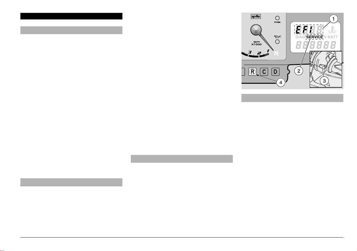
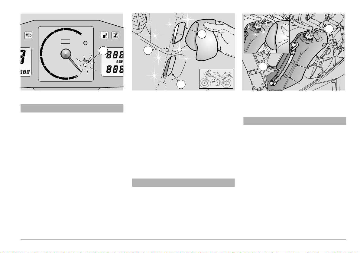
NOTE This vehicle is set so that any
anomaly can be detected in real time and
stored by th e electronic unit.
Whenever the ignition switch is brought to
position “2”, the writing "HIL" (1) appears
on the right side of the multifunction display
for approximately three seconds.
aCAUTION
If the writing “HIL” ( 1) is displayed
during the norm al operation o f the engine, this means that the electronic unit
has detected an anomaly.
In many cases, the en gine keeps running with redu ced performan ce levels;
immediately contact an APRILIA Offi cial
Dealer.
aCAUTION
After the first 1000 km (625 mi) and successively every 750 0 km (4687 mi), t he
word "SERVICE" (2) appears on the
right display.
In this case contact an APRILIA Official
Dealer, who will carry out the operations
indicated in the regular service inter vals
chart, see p. 60 (REGULAR SERVICE INTERVALS CHART). To make the writing
“SERVICE” disappear, press the “LAP”
push button (3) and then the push button r (4) and keep them pressed for
about five seconds.
use and maintenance RSV mille - RSV mille R
59
Page 2
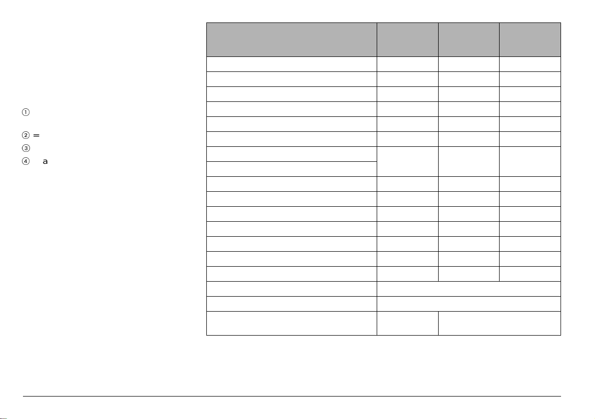
2%'5,!23%26)#%).4%26!,3
#(!24
OPERATIONS TO BE CARRIED OUT BY
THE APRILIA Official Dealer (WHICH
CAN BE CARRIED OUT EVEN BY THE
USER).
Key
= check and clean, adjust, lubricate or
change, if necessary;
= clean;
= change;
= adjust.
NOTE Perform the maintenance opera-
tions with doubled frequency if the vehicle
is used in rainy or dusty areas, on uneven
surfaces or on racetracks.
(*) = In case of use on racetracks, c ha nge
every 3750 km (2343 mi).
(**) = Check every two weeks or accord-
ing to the intervals indicated.
Component
After run-
ning-in [1000
km (625 mi)]
Every 7500
km (4687 mi)
or 12 months
Every 15000
km (9375 mi)
or 24 months
Spark plu gs (*)
Air cleaner
Engine oil filter (*)
Engine oil filter (on oil tank)
Fork
Light operation/directi on
Light system
Safety switches
Clutch fluid
Brake fluid
Coolant
Engine oil (*)
Tyres
Tyre pressure (**)
Engine idling rpm
Engine oil pressure warning light LED at every start:
Drive chain tension and lubrication every 1000 km (625 mi):
Brake pad wear
before every trip and every
2000 km (1250 mi):
use and maintenance RSV mille - RSV mille R
60
Page 3
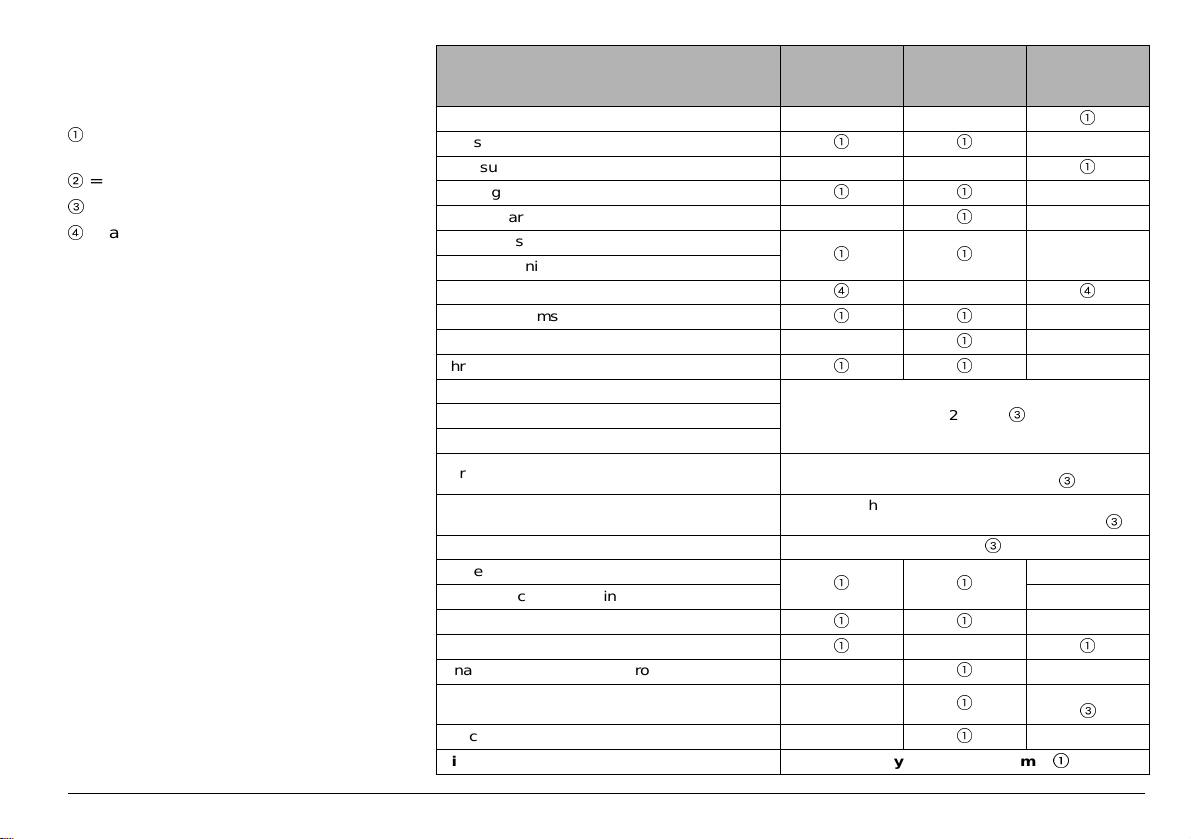
OPERATIONS TO BE CARRIED OUT BY
THE APRILIA Official Dealer.
Key
= check and clean, adjust, lubricate or
change, if necessary;
= clean;
= change;
= adjust.
NOTE Perform the maintenance opera-
tions with doubled frequency if the vehicle
is used in rainy or dusty areas, on uneven
surfaces or on racetracks.
(*) = In case of use on race tracks, check
every 3750 km (2343 mi).
(**) = With “R” fork w (W m), change
every 10000 km (6250 mi).
(***) = Only in case of:
– intense use on racetracks;
– participation in competitions.
After running-
Component
Rear shock absorber
Transmission cables and controls
Rear suspension linkage bearings
Steering bearings and steering clearance
Wheel bearings
Brake discs
General running of the vehicle
Adjusting the valve clearance
Braking systems
Cooling system
Throttle body pin greasing
Clutch fluid
Brake fluid
Coolant
Fork oil (**)
Fork oil seals
Brake pads if worn:
Wheel/Tyres
Nut, bolt, screw tightening
Cylinder synchronization
Suspensions and attitude
Final transmission (chain, crown and pinion)
Fuel pipes
Clutch wear (*)
Pistons (***) every 5000 km (3125 mi):
in [1000 km
(625 mi)]
after the first 7500 km (4687 mi) and successively
after the first 30000 km (18750 mi) and
successively every 22500 km (14000 mi):
Every 7500 km
(4687 mi) or 12
months
every 2 years:
every 22500 km (14000 mi):
Every 15000
km (9375 mi)
or 24 months
every 4 years:
use and maintenance RSV mille - RSV mille R
61
Page 4
)$%.4)&)#!4)/.$!4!
It is a good rule to w rite down the frame
and engine numbers in the space provided
in this manual.
The frame number ca n be us ed for th e purchase of spare parts.
NOTE Do not alter the identification
numbers if you do not want to incur severe
penal and administrative sanctions. In particular, the alteration of the frame number
results in the immediate inva lidity of the
guarantee.
use and maintenance RSV mille - RSV mille R
62
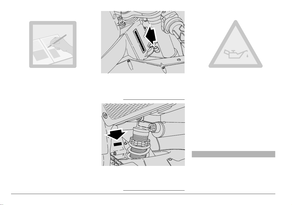
FRAME NUMBER
The frame number is stamped on the right
side of the steering column.
Frame no.
ENGINE NUMBER
The engine number is stamped on the rear
part of the engine, near the pinion.
Engine no.
#(%#+).'4(%%.').%/),
,%6%,!.$4/00).'50
Carefully read p. 43 (ENGINE OIL) and p.
59 (MAINTENANCE).
NOTE Perform the maintenance opera-
tions with doubled frequency if the vehicle
is used in rainy or dusty areas, on uneven
surfaces or on racetracks.
Periodically check the engine oil level,
change the oil after the first 1000 km (625
mi) and successively every 7500 km (4687
mi), see p. 64 (CHANGING THE ENGINE
OIL AND THE OIL FILTER).
aCAUTION
In case of use on racetracks, change
the engine oil every 3750 km (2343 mi).
If the vehicle is used in dusty areas,
change the oil more frequently.
Page 5
MAX
MIN
DIAG
km/h
X1000
rpm
BORLETTI
VEGLIA
N
max
1
2
3
4
5
6
7
8
9
10
11
12
A
A
MAX
2
4
3
M
A
MI
N
3
X
M
I
N
MAX
For the check, proceed as follows:
aCAUTION
The engine oil level must be checked
with warm engine.
If the check is carried out with cold engine, the oil level may temporarily lower
below the “MIN” mark.
This is not a problem, provided that the
engine oil pressure warning light LED
“.” (A) does not come on, see p. 18
(INSTRUMENTS AND INDICATORS TABLE).
NOTE To warm the engine and have the
engine oil reach th e operatin g temperatu re,
do not let the engine idl e with the v ehicl e at
rest. According to the correct procedure, it
is advisable to carry out the check after a
trip of after covering approximately 15 km
(10 mi) on a road outside to wn (this is sufficient for the engine oil to reach the operating temperature).
1
◆ Stop the engine, see p. 57 (STOPPING).
◆ Keep the vehicle in vertical position, with
the two wheels resting on the ground.
◆ Check the oil level on the transparent
pipe (3) through the a ppo si te slots (1 ) (2 )
on the left part of the fairing.
MAX = maximum level
MIN = minimum level.
The difference between “MAX” and “MIN”
amounts to approximately 500 cm#.
◆ The level is correct when the oil almost
reaches the “MAX” mark.
aCAUTION
Never exceed the “MAX” mark, nor
leave the oil below the “MIN” mark, in
order to avoid serious damage to the
engine.
If necessary, top up the engine oil by
proceeding as follows:
MIN
◆ Remove the left fairing, see p. 77 (RE-
MOVING THE SIDE FAIRINGS).
◆ Unscrew and remove the filling cap (4).
aCAUTION
Do not put additives or other substances into the oil.
If you use a funnel or other similar
items, make sure that they are perfectly
clean.
NOTE Use high-quality 15W – 50 oil,
see p. 113 (LUBRICANT CHART).
◆ Top up the tank and restore the correc t
level, see p. 113 (LUBRICANT CHART).
use and maintenance RSV mille - RSV mille R
63
Page 6

#(!.').'4(%%.').%/),!.$
4(%/),&),4%2
aCAUTION
The engine oil and the oil filter change
operations may be difficult for unskilled
operators.
If necessary, contact your APRILIA Official Dealer.
If you want to perform these operations
personally, keep to the follow ing instructions.
Carefully read p. 43 (ENGINE OIL) and p.
59 (MAINTENANCE).
NOTE Perform the maintenance opera-
tions with doubled frequency if the vehicle
is used in rainy or dusty areas, on uneven
surfaces or on racetracks.
Periodically check the engine oil level, see
p. 62 (CHECKING THE ENGINE OIL LEVEL AND TOPPING UP) change the oi l after
the first 1000 km (625 mi) a nd success ively
every 7500 km (4687 mi).
aCAUTION
In case of use on racetracks, change
the engine oil every 3750 km (2343 mi).
If the vehicle is used in dusty areas,
change the oil more frequently.
To change, proceed as follows:
NOTE The oil flows out completely and
without problems when it is warm and
therefore more fluid: to achieve this condition, the engine sho uld run for approximately twenty minutes.
use and maintenance RSV mille - RSV mille R
64
aCAUTION
When warmed up, the engine contains
hot oil; therefore, while carrying out the
operations describe d here below be
particularly careful, in order to avoid
burns.
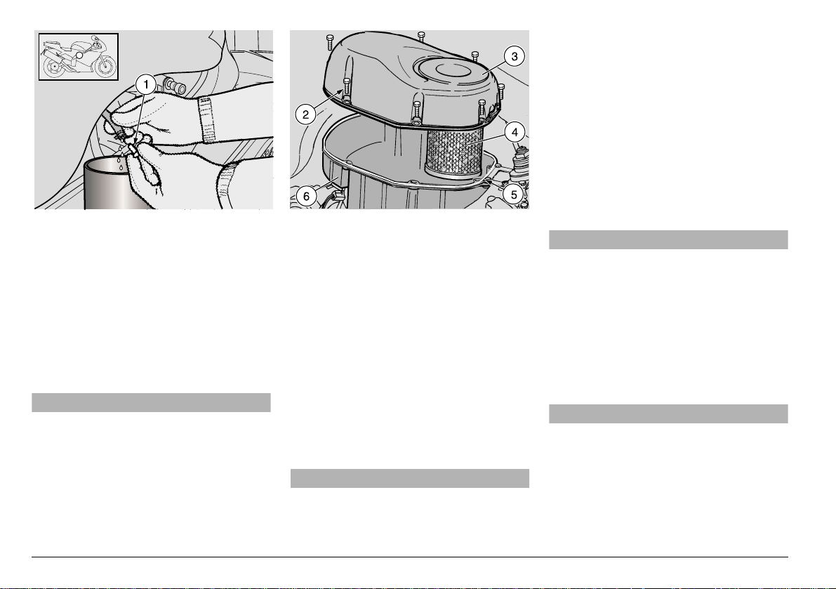
◆ Remove the lower fairing, see p. 77 (RE-
MOVING THE LOWER FAIRING).
◆ Position a container (1) with more than
4000 cm# capacity in correspondence
with the drain plug (2) positioned on the
tank.
◆ Unscrew and remove the drain plug (2)
positioned on the tank.
◆ Unscrew and remove the filling cap (3).
◆ Drain the oil and let it drip into the con-
tainer (1) for a few minutes.
◆ Check and if nec es sary replace the seal-
ing washer of t he drain plug (2) p ositioned on the tank.
◆ Screw and tighten the drain plug (2) on
the tank.
Drain plug (2) driving torque: 15 Nm
(1.5 kgm).
◆ Move the container (1 ) and p ositi on it un -
der the engine base, in correspondence
with the drain plug positioned on the engine (4).
◆ Unscrew and re move the drain plu g posi-
tioned on the engine (4).
◆ Drain the oil and let it drip into the con-
tainer (1) for a few minutes.
aCAUTION
Do not dispose of oil in the environment. Put it in a sealed containe r and
take it to the filling sta tion where you
usually buy it or to an oil salvage center.
◆ Remove the metal residues from the
drain plug (4) magnet.
Page 7

◆ Screw and tighten the drain plug (4).
Driving torque of the drain plug (4) positioned on the engine: 12 Nm (1.2 kgm).
CHANGING THE ENGINE OIL FILTER
NOTE Perform the maintenance opera-
tions with doubled frequency if the vehicle
is used in rainy or dusty areas, on uneven
surfaces or on racetracks.
Change the engine oil filter after the
first 1000 km (625 mi) and successively
every 7500 km (4687 mi) (or every time
you change the oil).
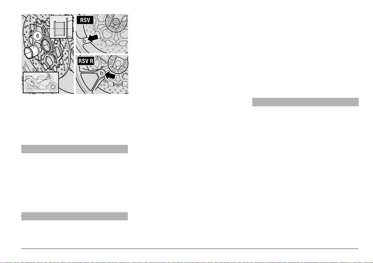
◆ Unscrew the two screws (5) and remove
the cover (6).
◆ Remove the engine oil filter (7).
aCAUTION
Do not use filters that have already
been used.
◆ Spread an oil film on the sealing ring (8)
of the new engine oil filter.
◆ Fit the new engine oil filter.
◆ Put back the cove r (6), sc rew and tighte n
the two screws (5).
CLEANING THE ENGINE OIL FILTER ON
THE TANK
NOTE Perform the maintenance opera-
tions with doubled frequency if the vehicle
is used in rainy or dusty areas, on uneven
surfaces or on racetracks.
Clean the engine oil filter (9) on the tank
after the first 1000 km (625 mi) and successively every 15000 km (9375 mi) (or
every two engine oil changes).
NOTE Prepare a screwdriver-type pipe
clamp (10) to re pl ace t he original one (special type).
◆ Loosen the clamp (11) and disconnect
the pipe ( 12).
◆ Unscrew and remove the engine oil filter
(9) positioned on the tank and clea n it
with a jet of compressed air.
◆ Check the seal of the engine oil filter (9)
positioned on the tank; screw and tighten
it.
Engine oil filter (9) drivin g torque: 30
Nm (3 kgm).
◆ Connect the pipe (12) and tighten the
new clamp (10).
aCAUTION
Do not put additives or other substances into the oil.
If you use a funnel or other similar
items, make sure that they are perfectly
clean.
NOTE Use high-quality 15W – 50 oil,
see p. 113 (LUBRICANT CHART).
◆ Pour about 3500 cm# of engine oil
through the filling opening (13), see p.
113 (LUBRICANT CHART).
◆ Tighten the filling cap (3).
◆ Start the engine, see p. 50 (STARTING)
and let it idle for about one minute, in order to ensure the fi lling up of the engine o il
circuit.
◆ Check the oil level and top up if neces-
sary, see p. 62 (CHECKING THE ENGINE OIL LEVEL AND TOPPING UP).
use and maintenance RSV mille - RSV mille R
65
Page 8
!)2#,%!.%2
NOTE Perform the maintenance opera-
tions with doubled frequency if the vehicle
is used in rainy or dusty areas, on uneven
surfaces or on racetracks.
Check the air cleaner every 7500 km (4687
mi) or 12 months, change it every 150 00 km
(9375 mi) or more frequently if the vehic le i s
used on dusty or wet roads.
It is possible to clean the air cleaner partially
after using the vehicle on this kind of roads.
aCAUTION
The partial cleaning of the filter does not
exclude or postpone the replacement of
the filter itself. Do not start the engine if
the air cleaner has been removed. Do
not clean the filtering element with petrol
or solvents, since they may cause a fire
in the fuel supply system, with serious
danger for the persons in the vicinity and
for the vehicle.
DO NOT DISPOSE OF POLLUTING SUBSTANCES OR COMPONENTS IN THE
ENVIRONMENT.
◆ Every 7500 km (4687 mi), remove the
plug (1), empty its conte nt i nto a co nta iner and deliver it to a salvage centre.
REMOVAL
◆ Lift the fuel tank, see p. 76 (LIFTING
THE FUEL TANK)
◆ Unscrew and remove the se ven screws
(2) that fasten the filter case cover (3).
◆ Remove the filter case cover (3).
◆ Extract the air cleaner (4).
◆ Check the conditions of the gasket (5)
and change it if it is damaged.
aCAUTION
Plug the opening wit h a clean cloth, i n
order to prevent any foreign matter to
get ito the suction ducts.
Upon reassembly, before positi oning
the filter case cover (3), make sure that
you have not left the cloth or other objects inside the filter case (6).
Make sure that the filtering element is
positioned correctly, in such a way as
to prevent non-filtered air from entering .
Remember that the untimely wea r of the
piston segments and the cylinder may
be caused by a faulty or uncorrectly positioned filtering element.
PARTIAL CLEANING
aCAUTION
Do not press or strike the metal net of
the air cleaner (4).
Do not use screwdrivers or alike.
◆ Seize the air cleaner (4) vertically and
strike it more than once on a clean surface.
◆ If necessary, clean the air cleaner (4)
with a compressed air jet (directing it
from the inside towards the outside of
the filter).
aCAUTION
When cleaning the filtering element,
make sure that there are no tears.
Otherwise, change the filtering el ement.
◆ Clean the outer part of the air cleaner (4)
with a clean cloth.
use and maintenance RSV mille - RSV mille R
66
Page 9
CHANGING
aCAUTION
Do not use filters that have already
been used.
◆ Replace the air cleaner (4) with a new
one of the same type.
!33%-",).'4(%0).3&/24(%
2%!23500/2434!.$
◆ Position the vehicle on the stand, see p.
58 (POSITIONING THE VEHICLE ON
THE STAND).
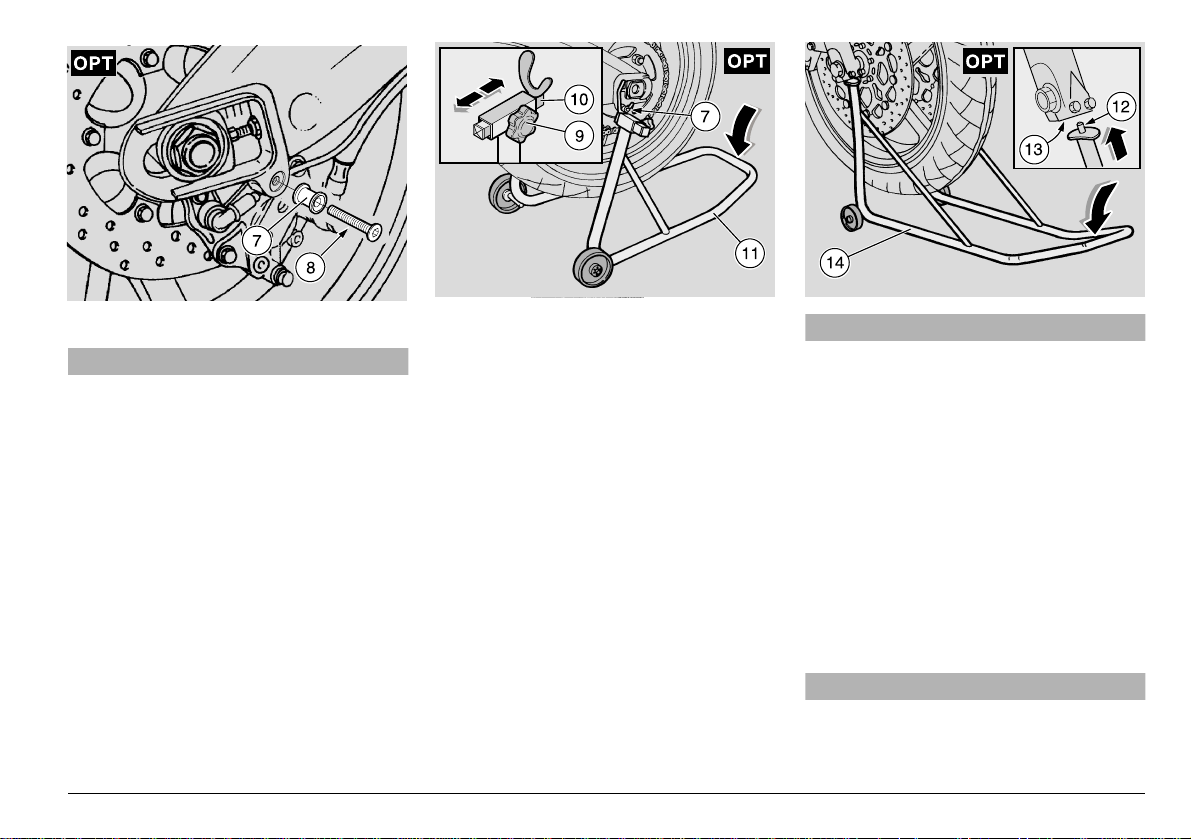
~Position the pin (7) on the appropriate
seat on the rear fork.
~Screw and tighten the screw (8) in the
appropriate threaded hole in the rear
fork.
m
0/3)4)/.).'4(%6%()#,%/.
4(%2%!23500/2434!.$
◆ Assemble the two pins (7), see p. 67
(ASSEMBLING THE PINS FOR THE
REAR SUPPORT STAND m).
m
NOTE Have someone help you k eep the
vehicle in vertical position with the two
wheels on the ground.
~Loosen the knob (9).
~Move the fork support (10), positioning
it so that the width corr esponds to the
distance between the two pins (7) on the
rear fork.
~Tighten the knob (9).
◆ At the same time introduce the two fork-
shaped seats (10) of the stand (1 1) under the two pins (7) provided on the v ehicle.
◆ Rest one foot on the rear part of the
stand (11).
◆ Push the stand (11) downwards until it
reaches the end of its stroke.
aCAUTION
Make sure that the vehicle is stable.
0/3)4)/.).'4(%6%()#,%/.
4(%&2/.43500/2434!.$
◆ Position the vehicle on the appropriate
rear support stand, see p. 67 (ASSEMBLING THE PINS FOR THE REAR
SUPPORT STAND m).
◆ Insert the two ends of the stand (12) in
the two holes (13) positioned on the lower ends of the front fork.
◆ Rest one foot on the front part of the
stand (14).
◆ Push the stand (14) downwards until it
reaches the end of its stroke.
m
aCAUTION
Make sure that the vehicle is stable.
use and maintenance RSV mille - RSV mille R
67
Page 10
&2/.47(%%,
aCAUTION
The disassembly and reassembly of the
front wheel may be difficu lt for unskille d
operators.
If necessary, contact your APRILIA Official Dealer.
If you want to perform these operations
personally, keep to the following in structions.
Carefully read p. 59 (MAINTENANCE).
While disassembling and reassembling
the wheel, be careful not to damage the
brake pipes, the discs and the pads.
aWARNING
Riding with damaged rims may be dangerous for the rider, other persons and
the vehicle.
Check the conditions of the wheel rim
and change it if it is damaged.
DISASSEMBLY
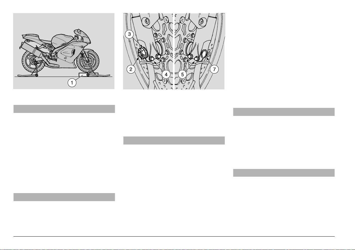
◆ Remove the front brake calipers, see p.
70 (FRONT BRAKE CALIPERS).
◆ Put a support (1) under the tyre, in such
a way as to keep th e w h eel in its position
after loosening it.
aCAUTION
Make sure that the vehicle is stable.
◆ Have someone keep the handlebar
steady in running position, so that the
steering is locked.
Wheel nut (2) driving torque: 80 Nm (8
kgm).
◆ Loosen and remove the wheel nut (2),
taking the washer (3).
Wheel pin clamp screw driving torque:
22 Nm (2.2 kgm).
◆ Partially unscrew the two wheel pin
clamp screws (4) (right side).
◆ Partially unscrew the two wheel pin
clamp screws (5) (left side).
NOTE Check the position of the spacer
ring (6) (right side ), in order to be able to
reinstall it correctly.
NOTE To facilitate the extraction of the
wheel pin, slightly raise the wheel.
◆ Push the wheel pin (7), b y carefully acting
on the threaded end and using a rubber
hammer if necessary.
◆ Support the front wheel and manually
withdraw the wheel pin (7).
◆ Remove the whee l by wit hdrawing it from
the front.
aCAUTION
The spacer ring (6) remains in its seat
on the wheel; if it comes off, reposition
it correctly (see REASSEMBLY).
REASSEMBLY
◆ Spread a film of lubrica ting grease on the
whole leng th of th e wheel pin (7 ), see p.
113 (LUBRICANT CHART).
aCAUTION
While reassembling the wheel, be careful not to damage the b rake pipes, discs
and pads.
use and maintenance RSV mille - RSV mille R
68
Page 11
NOTE Eseguire l’operazione che segue,
solo se il distanziale (6) è fuoriuscito dalla
sede.
◆ Insert the spacer ring (6) with its longer
diameter towards t he o uts id e of the ve hicle.
aCAUTION
The arrow on the wheel side indicates
the rotation direction.
Upon reassembly, make sure that the
wheel is positioned correctly: the arrow
must be visible on the le ft side of the vehicle.
◆ Position the wheel between the fork rods
on the support (1).
aWARNING
Danger of injury. Do not introduce your
fingers to align the holes.
◆ Move the wheel until its central hole and
the holes on the fork are aligned.
◆ Introduce the wheel pin (7) completely
from the left side.
NOTE Make sure that the wheel pin (7)
is completely inserted.
◆ Position the washer (3) and tighten the
wheel nut (2) manually.
NOTE In this phase, for the temporary
tightening of the two wheel pin clamp
screws (5) (left side), the driving to rque value need not be respected.
◆ Screw the two wheel pin clamp screws
(5) (left side) and tighten them as much
as necessary to lock the rotation of the
wheel pin (7).
◆ Tighten the wheel nut (2) completely.
Wheel nut (2) driving torque: 80 Nm (8
kgm).
◆ Tighten the two wheel pin clamp screws
(4) (right side).
Wheel pin clamp screw driving torque:
22 Nm (2.2 kgm).
◆ Loosen the two wheel pin clamp screws
(5) (left side).
◆ Put back the front brake calipers, see p.
70 (FRONT BRAKE CALIPERS).
◆ With pulled front brake lever, press the
handlebar repeatedly, thr usting the fork
downwards. In this way the fork rods will
settle properly.
◆ Position the vehicle on the side stand,
see p. 58 (POSITIONING THE VEHICLE
ON THE STAND).
◆ Tighten the two screws (5) of the wheel
pin clamp (left side).
Wheel pin clamp screw driving torque
(5): 22 Nm (2.2 kgm)
◆ Make sure that the followi ng compo nents
are not dirty:
– tyre;
– wheel;
– brake discs.
aWARNING
After reassembly, pull the front brake lever repeatedly and check the correct
functioning of the braking system.
Check the wheel centering.
Have the driving torques, centering and
balancing of the wheel checked by your
APRILIA Official Dealer, in order to avoid
accidents that may be harmful for you
and/or other people.
use and maintenance RSV mille - RSV mille R
69
Page 12
&2/.4"2!+%#!,)0%23
Carefully read p. 59 (MAINTENANCE).
aWARNING
A dirty disc soils the pads, with consequent reduction of the braking efficiency. Dirty pads must be replaced, while
dirty discs must be cleaned with a highquality degreaser.
aCAUTION
While disassembling and reassembling
the wheel, be careful not to damage the
brake pipes, the discs and the pads.
NOTE To remove the front brake cali-
pers, it is necessary to use the appropriate
front m and rear support stands m.
DISASSEMBLY
◆ Position the vehicle on the appropriate
front support stand, see p. 67 (POSITIONING THE VEHICLE ON THE
FRONT SUPPORT STAND m).
aCAUTION
Make sure that the vehicle is stable.
◆ Manually rotate the wheel, so that the
space between two spokes of the rim is
in correspondence with t he brake caliper.
◆ Have someone keep the handlebar
steady in running position, so that the
steering is locked.
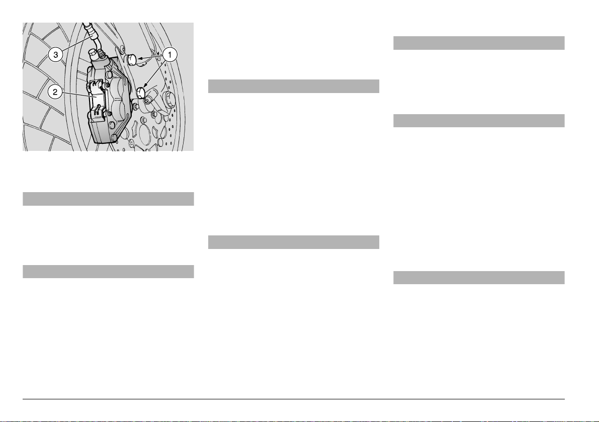
Brake caliper screw dri ving torque (1):
50 Nm (5 kgm).
◆✱ Unscrew and remove the two brake
caliper screws (1).
aCAUTION
Never pull the brake lever after removing the caliper, otherwise the pistons
may go out of their seats, thus causing
the outflow of the brake fluid.
In this case consult y our APRILIA Offic ial
Dealer, who will carry out the proper
maintenance operation.
◆✱ Withdraw the brake caliper (2) from
the disc, leaving it attached to the pipe
(3).
Work on the second brake caliper:
◆ Repeat the operations marked with ✱.
REASSEMBLY
aCAUTION
Proceed with care, in order not to damage the brake pads.
◆✖ Insert the brake caliper (2) on the disc
and position it so that its fastening holes
and the holes o n the suppo rt ar e alig ned.
aWARNING
Upon reassembly of the brake caliper,
replace the caliper fastening screws (1)
with two new screws of the same type.
◆✖ Screw and tighten the two screws (1)
that fasten the brake caliper.
Brake caliper screw driving torque:
50 Nm (5 kgm).
Work on the second brake caliper:
◆ Repeat the operations marked with ✖.
◆ Remove the front support stand m, see
p. 67 (POSITIONING THE VEHICLE ON
THE FRONT SUPPORT STAND m).
aCAUTION
After reassembly, pull the brake lever
repeatedly and check the correct functioning of the braking system.
use and maintenance RSV mille - RSV mille R
70
Page 13
2%!27(%%,
aCAUTION
The disassembly and reassembly of the
rear wheel may be difficult for unskilled
operators.
If necessary, contact your APRILIA Offi-
cial Dealer.
If you want to per form these operat ions
personally, keep to the following instructions.
Carefully read p. 59 (MAINTENANCE).
Before carrying out the following opera-
tions, let the engine and the silencer
cool down until the y reach room temperature, in order to avoid burns.
While disassembling and reassembling
the wheel, be careful not to damage the
brake pipe, the disc and the pads.
aWARNING
Riding with damaged rims may be dangerous for the rider, other persons and
the vehicle.
Check the conditions of the wheel rim
and change it if it is damaged.
NOTE To remove the rear wheel it is
necessary to use the appropriate rear support stand m.
DISASSEMBLY
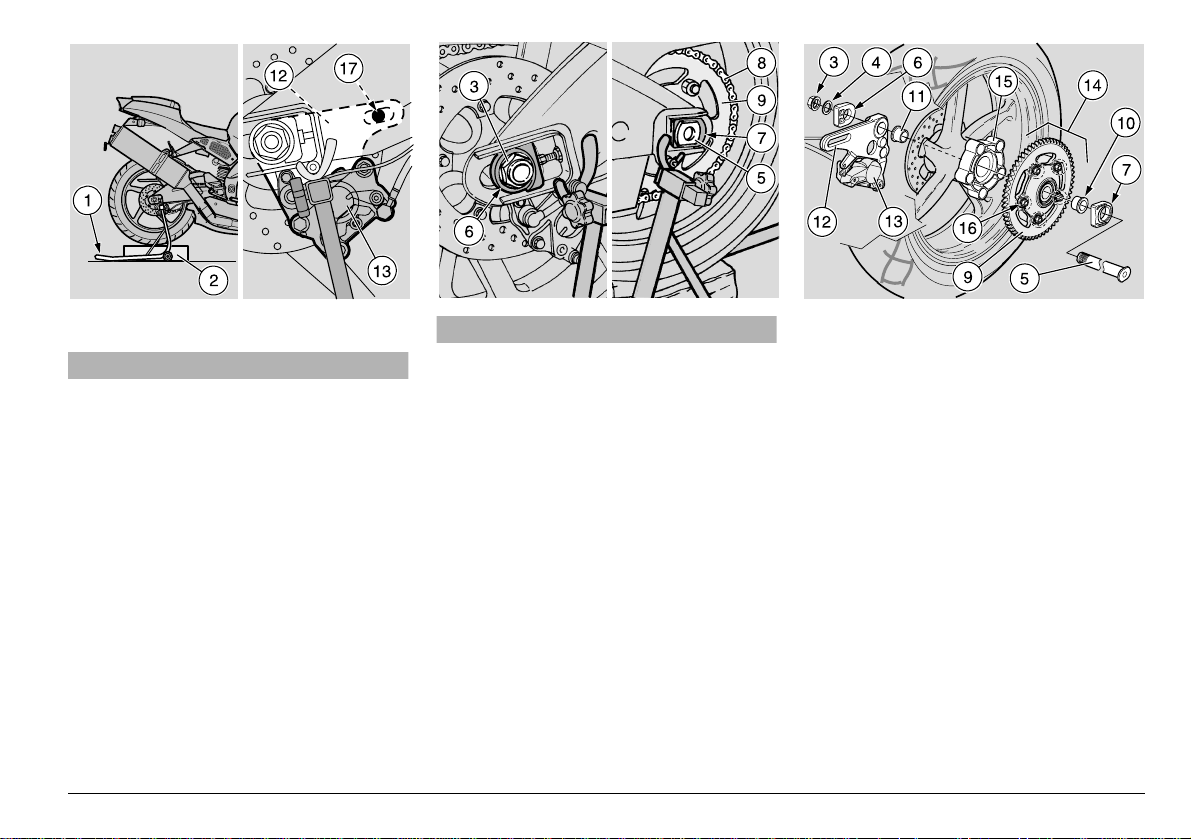
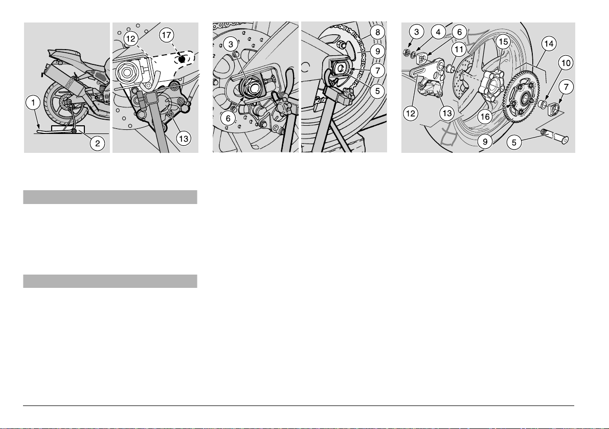
◆ Position the vehicle on the appropriate
rear support stand (1), see p. 67 (POSITIONING THE VEHICLE ON THE REAR
SUPPORT STAND m).
◆ Put a support (2) under the tyre, in such
a way as to keep the wheel in its position
after loosening it.
Wheel nut (3) driving torque: 120 Nm
(12 kgm).
◆ Loosen and remove the wheel nut (3),
taking the washer (4).
NOTE To facilitate the extraction of the
wheel, slightly raise the wheel.
◆ Withdraw the wheel pin (5) from the left
side.
NOTE Check the arrangement of the
right (6) and left (7) chain tighteners, in order to be able to reassemble them correctly.
◆ Take the right (6) and left (7) chain tight-
eners.
NOTE Lower the drive chain (8) outside
the crown gear (9).
◆ Make the wheel a dvance and releas e the
drive chain (8) from the crown gear (9).
◆ Withdraw the wheel from the rear fork
use and maintenance RSV mille - RSV mille R
71
Page 14
from behind, carefully withdrawing the
disc from the brake caliper.
aCAUTION
Do not operate the rear br ak e le ver after
removing the wheel, since the pins may
go out of their seats and cause brake
fluid leakages. In this case con sult your
APRILIA Official Dealer, who will carry
out the proper maintenance operation.
aCAUTION
The left (10) and right spacer rings (11)
remain positioned in the respective
seats on the wheel; if they should come
off, reposition them correctly (see REASSEMBLY).
NOTE The support plate (12) of the
brake caliper (13) remains positioned on
the right side of the rear fork.
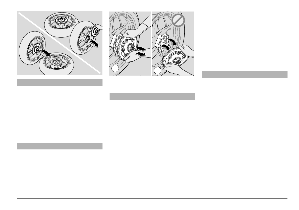
Proceed with care. If the final drive unit
(14) is installed on the flexible coupling
use and maintenance RSV mille - RSV mille R
72
holder (15), do not overturn or rotate the
rear wheel in horizontal position on the rear
sprocket side (A), since the final drive unit
would come off and fall down, with the risk
of damaging the rear sprocket (9) .
NOTE The removal of the final drive unit
isn’t necessary if the wh ee l is in t he normal
running position (vertical) or in horizontal
position with the rear sprocket facing upwards and in both cases se cured against
overturning.
NOTE Do not unscrew the five nuts (16).
The whole final drive unit must be withdrawn from the flexible coupling holder.
◆ Working (B) with both hands on th e outer
diameter of the sprocket (9), withdraw
the final drive unit parallel y to the wh eel
axis.
REASSEMBLY
If the final drive unit (14) has been re-
moved:
NOTE Introduce the final drive unit, par-
allely to the wheel axis, inserting the flexible coupling rubber elements in the corresponding seats on the flexible coupling
holder (15).
◆ Working (C) with both han ds on the oute r
diameter of the sprocket (9), insert the final drive unit in the flexible coupling
holder (15).
NOTE Perform the operation described
below only if the left (10) and/or the right
spacer ring (11) have come off their seats.
◆ Insert the left (10) and/o r the right sp acer
ring (11) in the respective seats, with the
longer diameter towards the outside of
the vehicle.
Page 15
C
OK !
NO!
B
OK !
OK !
OK !
NO!
A
A
NO!
aCAUTION
Before proceeding with the reassembly,
make sure that support plate (12) of the
brake caliper (13) is positioned correctly; the plat e sl o t must b e in se r te d i n th e
appropriate stop pin (17) in the inner
part of the rear fork right rod.
Insert th e d isc in t he b r ak e cal ip e r ca r e fully.
◆ Position the wheel between the rear fork
rods on the support (2).
Do not introduce yo ur fingers betw een
the chain and the crown gear.
◆ Make the wheel advance and position
the drive chain (8) on the crown gear (9).
◆ Correctly insert the right (6) and left (7)
chain tighteners in their seats on the
fork.
◆ Uniformly apply a moderate quantity of
aWARNING
OK !
OK !
NO!
C
B
9
grease on the wheel pin (5), see p. 113
(LUBRICANT CHART).
9
aWARNING
Danger of injury.
Do not introduce your fingers to align
the holes.
◆ Move the wheel backward s, unt il its ce n-
tral hole and the holes on the rear fork
are aligned.
◆ Rotate the support plate (12), complete
with brake caliper (13) and with fulcrum
on the stop pin (17 ), until it i s aligned w ith
the holes.
◆ Introduce the wheel pin (5) completely
from the left side.
NOTE Make sure that the wheel pin (5)
is completely inserted, with the head in the
relevant seat on the l eft c hain tightener (7).
◆ Position the washer and tighten the
wheel nut (3) manually.
◆ Check the chain tension, see p. 74
(DRIVE CHAIN).
◆ Tighten the wheel nut (3).
Wheel nut (3) driving torque: 120 Nm
(12 kgm).
◆ Make sure that the followi ng compo nents
are not dirty:
– tyre;
– wheel;
– brake discs.
aCAUTION
After reassembly, pull the rear brake lever repeatedly and check the correct
functioning of the braking system.
Check the wheel centering.
Have the driving torques, centering and
balancing of the wheel checked by your
APRILIA Official Dealer, in order to avoid
accidents that may be harmful for you
and/or other people.
use and maintenance RSV mille - RSV mille R
73
Page 16

$2)6%#(!).
Carefully read p. 59 (MAINTENANCE).
The vehicle is equipped with an endle ss
chain, in which a ring link joint is not used.
aCAUTION
An excessive slackening of the chain
may cause noise or make the chain rattle, with consequent wear of the shoe
and of the chain guide plate.
Periodically check the slack and adjust it
if necessary, see p. 74 (ADJUSTMENT).
To change the chain, contact an APRILIA
Official Dealer, who will ensure you
prompt and accurate servicing.
Incorrect main tenance may cause the
untimely wear of the chain and/or damages to the pinion and/or the crown.
NOTE Perform the maintenance opera-
tions with doubled frequency if the vehicle
is used in rainy or dusty areas, on uneven
surfaces or on racetracks.
use and maintenance RSV mille - RSV mille R
74
CHECKING THE SLACK
To check the slack, proceed as follows:
◆ Stop the engine.
◆ Position the vehicle on the stand, see p.
58 (POSITIONING THE VEHICLE ON
THE STAND).
◆ Position the shifting lever in neutral.
◆ Make sure that the v ertica l osci llat ion, in
an intermediate point between pinion
and crown in the lower part of the chain,
is about 25 mm.
◆ Move the vehicle forwards, or turn the
wheel, in order to be able to check the
vertical oscillation of the chain even when
the wheel turns; the slack must be constant in all the rotation phases of the
wheel.
aCAUTION
If in some positions the slack is higher
than in others, this means that the re are
crushed or seized links; in this case,
contact an APRILIA Official Dealer. To
prevent the ri sk of seizures, lub ricate
the chain frequently, see p. 75 (CLEANING AND LUBRICATION).
If the slack is uniform, but higher or lower
than 25 mm, adjust it, see p. 74 (ADJUSTMENT).
ADJUSTMENT
NOTE To adjust the chain it is n ecessary
to use the appropri ate rear support st and
.
m
If after the check it is necessary to adjust
the chain tension, proceed as follows:
◆ Position the vehicle on the appropriate
rear support stand, see p. 67 (POSITIONING THE VEHICLE ON THE REAR
SUPPORT STAND m).
◆ Loosen the nut (1) completely.
NOTE For the wheel centering fixed ref-
erence marks (2-3) are provided, which
can be seen inside the chain tightener
seats on the rear fork arms, before the
wheel pin.
◆ Loosen the two lock nuts (4).
◆ Act on the a djusters (5) and adjust the
chain slack, making sure that the reference marks (2-3) are correctly positione d
on both sides of the vehicle.
Page 17

◆ Tighten the two lock nuts (4).
◆ Tighten the nut (1).
Wheel nut (1) driving torque: 120 Nm
(12 kgm).
◆ Check the chain slack, see p. 74
(CHECKING THE SLACK).
CHECK ING THE DRIVING CHAIN, PINION AND SPROCKET WEAR
Further, check the following parts every
7500 km (4687 mi) and make sure that
chain, pinion and crown do not present:
– damaged rollers;
– loose pins;
– dry, rusty, crushed or seized links;
– excessive wear;
– lacking O rings;
– sprocket or teeth excessively worn or
damaged.
aCAUTION
If the chain rollers are damaged, the
pins are loose and/or the O rings are
damaged or lacking, it is necessary to
change the whole chain unit (both
sprockets and chain).
Lubricate the chain frequently, especially if there are dry or rusty parts.
The crushed or seized links must be lubricated and made work again.
If this is not possible, contact an APRIL
IA Official Dealer, who will provide for
changing the chain.
◆ Check the wear of the ch ain plasti c guide
(6).
◆ Finally, check the wear of the rear fork
protection shoe (7).
CLEANING AND LUBRICATION
aCAUTION
The drive chain is pro vide d with O rings
among the links, in order to keep the
grease inside them.
Carry out the adju stment, lubricat ion,
cleaning and change of the chain with
great care.
Never wash the chain with water jets,
steam jets, high-p ressure water je ts and
highly inflammable solvents.
◆ Wash the chain with naphtha or kero-
sene. If it tends to rust quickly, intensify
the maintenance intervals.
Lubricate the chain every 1000 km (625
mi) or whenever necessary.
◆ After washing the chain and letting it
dry, lubricate it with spray grease for
chains provided with sealing rings, see
p. 113 (LUBRICANT CHART).
aCAUTION
The lubricants for chains available on
the market may contain substances that
are dangerous for the rubber sealing
rings of the chain.
NOTE Do not use the vehicle soon after
lubricating the chain, since due to the centrifugal force the lubricant would be
sprayed outwards and dir ty the surrounding areas.
use and maintenance RSV mille - RSV mille R
75
Page 18

2%-/6).'4(%2)$%23!$$,%
◆ Position the vehicle on the stand, see p.
58 (POSITIONING THE VEHICLE ON
THE STAND).
~Partially raise the rear side edge of the
saddle.
~Unscrew and remove the screw (1)
and take the bushing (2).
Screw (1) driving torque: 12 Nm (1.2
kgm).
◆ Raise and remove the saddle (3).
NOTE Upon reassembly, insert the front
tang of the saddle in the appropriate seat.
aCAUTION
Before leaving, make sure that the saddle (3) is properly positioned and
locked.
use and maintenance RSV mille - RSV mille R
76
,)&4).'4(%&5%,4!.+
Carefully read p. 33 (FUEL) and p. 59
(MAINTENANCE).
aWARNING
Risk of fire.
Wait until the engine and the exh aus t silencer have completely cooled down.
Fuel vapours are noxio us for your
health.
Before procee ding, make sure that the
room in which you are working is properly ventilated.
Do not inhale fuel vapours.
Do not smoke and do not use naked
flames.
DO NOT DISPOSE OF FUEL IN THE ENVIRONMENT.
ú Remove the passenger seat (or the
glove/tool kit compartment cover m),
see p. 29 (UNLOCKING/LOCKING THE
PASSENGER SEAT W).
÷ Remove the glov e/tool kit comp art-
ment cover, see p. 30 (UNLOCKING/LOCKING THE GLOVE/TOOL KIT
COMPARTMENT COVER w).
◆ Remove the rider saddle, see p. 76 (RE-
MOVING THE RIDER SADDLE).
◆ Unscrew and remove the two screws (4)
that fasten the front part of the fuel tank
(5).
◆ Remove the fuel tank support rod (8)
from the relevant anchorage seats (6-7).
NOTE The rubber-covered end of the
rod (8) must be introduced in the central
hole of the steering pin.
◆ Lift the front part of the fuel tank (5) and
introduce the rod (8) as indicated in the
figure.
Page 19

2%-/6).'4(%3)$%&!)2).'3
Carefully read p. 59 (MAINTENANCE).
aWARNING
Wait until the engine and the exh aus t silencer have completely cooled down.
◆ Position the vehicle on the stand, see p.
58 (POSITIONING THE VEHICLE ON
THE STAND).
◆ Rotate the six rapid fastening screws (1)
by giving them 1/4 turn anticlockwise.
aCAUTION
Handle the plastic and painted components with care to avoid scraping or
damaging them.
◆ Remove the side fairing (2).
NOTE Repeat these operations to re-
move the other side fairing.
2%-/6).'4(%,/7%2&!)2).'
Carefully read p. 59 (MAINTENANCE).
NOTE To remove the lower fairing, it is
necessary to use the appropriate rear support stand m.
◆ Position the vehicle on the appropriate
rear support stand, see p. 67 (POSITIONING THE VEHICLE ON THE REAR
SUPPORT STAND m).
◆ Remove the two side fairings, see p. 77
(REMOVING THE SIDE FAIRINGS).
◆ Unscrew and remove the two front
screws (3).
~Unscrew and remove the rear screw
(4).
◆ Unscrew and remove the two screws (5)
of the rear right profile (6) (inside the exhaust silencer).
aCAUTION
Handle the plastic and painted components with care to avoid scraping or
damaging them.
◆ Let the side stand down.
◆ Withdraw the two pipes (7-8) from the
hole provided on the fairing.
◆ Remove the entire lower fairing (9) by
lowering it and with small movements try
to find the best position to withdraw it
from the side stand.
NOTE Upon reassembly, introduce the
two pipes (7-8) in the hole provided on the
fairing.
◆ Take the rear right profile (6).
NOTE Upon reassembly, the upper part
of the profile (6) must b e fi tted bet ween the
lower fairing (9) and the support plate.
use and maintenance RSV mille - RSV mille R
77
Page 20

2%-/6).'4(%3)$%#/6%23
◆ Remove the rider saddle, see p. 76 (RE-
MOVING THE RIDER SADDLE).
◆ Unscrew and remove the two screws (1 ).
aCAUTION
Handle the plastic and painted components with care to avoid scraping or
damaging them.
◆ Remove the side cover (2).
NOTE Upon reassembly, make sure that
the rear coupling is positioned correctly.
Repeat these operation s to remove the
other side cover.
use and maintenance RSV mille - RSV mille R
78
2%-/6).'4(%2%!26)%7
-)22/23
◆ Position the vehicle on the stand, see p.
58 (POSITIONING THE VEHICLE ON
THE STAND).
◆ Unscrew and remove the nut (3), take
the washer (4), the spring (5) and the
half sphere (6).
aCAUTION
Handle the plastic and painted components with care to avoid scraping or
damaging them.
◆ Remove the rear-view mirror (7).
◆ If it has gone out of its seat, take the cup
(8).
NOTE Repeat these operations to re-
move the other rear-view mirror.
aCAUTION
After reassembly, correctly adju st the
rear-view mirrors and tighten th e nuts in
such a way as to ensure their stability.
After reassembly:
◆ Adjust the inclination of the rear-view
mirrors correctly.
Page 21

2%-/6).'4(% &2/.40!24/&
4(%&!)2).'
◆ Position the vehicle on the stand, see p.
58 (POSITIONING THE VEHICLE ON
THE STAND).
◆ Turn the ignition switch to position “1”.
◆ Unscrew and remove the two lower
screws (1).
~Unscrew and remove the side screw
(2).
aCAUTION
Upon reassembly, tighten the screw (2)
moderately, since it is fixed on plastic.
~Unscrew and remove the two upper
screws (3).
NOTE Upon reassembly, rotate th e rear-
view mirror support so that the fastening
holes coincide with those provided on the
front part of the fairing.
The whole unit must be correctly positioned on the support.
◆ Move the front part of the fairing (4)
slightly forward.
◆ Raise the protection element (5).
◆ Disconnect the electric connector (6) of
the headlight.
aCAUTION
Upon reassembl y, make sure that the
electric connector (6) is correctly coupled.
aCAUTION
Handle the plastic and painted components with care to avoid scraping or
damaging them.
◆ Remove the front part of the fairing (4)
completely, together with the headlight
and the rear-view mirrors.
After reassembly:
◆ Adjust the inclination of the rear-view
mirrors correctly.
use and maintenance RSV mille - RSV mille R
79
Page 22

3
1
4
2%-/6).'4(%3)$%34!.$
Carefully read p. 59 (MAINTENANCE).
Only when the vehicle must be used on
racetracks, it is advi sable to remove the
stand (1) complete with:
– springs (2);
– support (3);
– safety switch (4).
2
6
5
NOTE The removal of the safety switch
(4) disconnects the electric circuit; to restore it, connect the wiring (6) (aprilia part
# 8124943), which is av ailab le at a ny april-
ia Official Dealer, to the connector (5).
aCAUTION
Neither lean the vehicle against walls,
nor lay it on the ground.
To park the vehicle without stand (the
removal of the stand is allowed only for
the use of the vehicle on rac etrac ks), always and exclusively use the rear support stand m.
aWARNING
It is forbidden to disconnect or remove
the safety switch (4) separately from the
stand.
The disconnection or removal of the
safety swit ch (4) alo ne makes it possible to start the vehicle and leave with
the stand do wn, which may re sult in a
fall and in serious injuries to the rider
and other people and damage to the vehicle itself.
For the removal, proceed as follows:
◆ Remove the left side cover, see p. 78
(REMOVING THE SIDE COVERS).
◆ Remove the lower fairi ng, see p. 77 (R E-
MOVING THE LOWER FAIRING).
◆ Lift the fuel tank, see p. 76 (LIFTING
THE FUEL TANK)
NOTE Prepare a clamp (7) to be used
for the reassembly.
aCAUTION
Do not force cables, pipes, connec tors
and wires.
◆ Cut the clamp (8) and release the cable
(9).
◆ Disconnect the electric connector (10)
from the connector (5).
◆ Connect the wiring (6) (aprilia part #
8124943) [replacing the electric connector (10)].
use and maintenance RSV mille - RSV mille R
80
Page 23

12
9
11
3
◆ Withdraw the cable (9) completely.
◆ Put back the fuel tank, see p. 76 (LIFT-
ING THE FUEL TANK).
◆ Put back the left side cover, see p. 78
(REMOVING THE SIDE COVERS).
NOTE Support the stand, in order to pre-
vent it from accidentally falling down.
◆ Unscrew and remove the screws (11)
and take the washers (12).
◆ Remove the stand (1) complete with:
– springs (2);
– support (3);
– safety switch (4).
11
12
12
11
NOTE Store the following components
together: complete stand, screws (11) and
washers (12), in order to be able to install
them correctly when the vehicle must be
used on road s.
◆ Put back the lower fairing (and the two
side fairings), see p.77 (REMOVING
THE LOWER FAIRING).
4
use and maintenance RSV mille - RSV mille R
2
1
81
Page 24

).30%#4).'4(%&2/.4!.$
2%!23530%.3)/.3
Carefully read p. 59 (MAINTENANCE).
NOTE Have the front fork oil changed by
an aprilia Official Dealer, who will ensure
you prompt and accurate servicing.
NOTE Perform the maintenance opera-
tions with doubled frequency if the vehicle
is used in rainy or dusty areas, on uneven
surfaces or on racetracks.
Have the front fork o il changed after the first
7500 km (4687 mi) and successively every
22500 km (14000 mi ).
With “R” front fork w (W m), have the
oil changed every 10000 km (6250 mi).
use and maintenance RSV mille - RSV mille R
82
Carry out the following check s after the first
1000 km (625 mi) and successively every
15000 km (9375 mi):
◆ With pulled front brake lever, press the
handlebar repeate dly, thrusting the fork
downwards. The stroke must be gentle
and there must be no trace of oil on the
rods.
◆ Check the fastening of all the compo-
nents and the funct ionality of the front
and rear suspension joints.
aCAUTION
If you notice irregularities in the operation or if the help of a qualified tech nician is necessary, contact your APRILIA
Official Dealer.
&2/.43530%.3)/.
Have the fork oil s eals change d by a aprilia
Official Dealer after the first 30000 km
(1875 mi) and successively every 22500
km (14000 mi).
The front suspension consists of an hydraulic fork connected to the steering column by means of tw o pl ates.
For the setting of the vehicle attitude, each
rod of the fork is provided with an upper
screw (1) for the adjustment of the hydraulic braking with extended shoc k absorber, a
lower screw (2) for the adjustment of the
hydraulic brakin g with compressed sh ock
absorber and an upper nut (3) for the adjustment of the spri ng pre load.
ADJUSTING THE FRONT FORK
aCAUTION
Do not force the rotati on of the adjusters (1-2) beyond the end of stroke in
both directions, in order to avoid any
Page 25

damage. Set t he same spring pr eload
and hydraulic braking for both rods: a
different setting of the rods decreases
the stability of the vehicle while riding.
When the spring preload is increased, it
is necessary to increase also the hydraulic braking, in order to avoid sudden jerks while riding.
For the adjustment of the fork:
– W see p. 83 (FORK W);
– w (W m) see p. 84 [“R” FORK w (W
m)].
FORK W
The standard setting of the front fork is
such as to sati sfy most driving conditions
at low and high speed, either with reduced
load and full load.
However, it is also possible to adjust the
setting according to the in tended use of the
vehicle.
aCAUTION
For the adjustment , always start from
the most rigid setting [complete clockwise rotation of the adjus ter s ( 1-2)]. Use
the notches (1-2) provided on the adjusters as reference marks for the adjustment of the hydraulic braking with
compressed and extended shock absorber.
Gradually rotate the adjusters (1-2) giving 1/8 turn per time.
Test the vehicle repeatedly on the road,
until obtaining the optimal adjustment.
Front suspension Standard adjust-
Hydraulic adjustment with
extended shock absorber, screw (1)
Hydraulic adjustment with
compressed shock absorber, screw (2)
Spring preload, nut (3)
Protrusion of the rods (A)
(***) from the upper plate
(plug excluded)
(*) = clockwise
(**) = anticlockwise
(***) = Have this type of adjustment carried out exclusively by an aprilia Offic ial Deal er
ment
from completely
closed (*) open (**)
1.25 turns
from completely
closed (*) (H) open
(**) (S)
1 turns
from completely closed (*) open (**)
4 – 5 reference notches
3 refere nce notches
Adjustment for
racetrack use
from completely
closed (*) open (**)
0.5 – 1 turn
from completely
closed (*) (H) open
(**) (S)
0.5 – 1 turn
use and maintenance RSV mille - RSV mille R
Possible
adjustments
from completely
closed (*) open (**)
0.5 – 1.5 turns
from completely
closed (*) open (**)
0.5 – 2 turns
from completely
closed (*) open (**)
3 – 5 reference
notches
2 – 4 reference
notches
83
Page 26

“R” FORK w (W m)
The standard setting of the front fork is adjusted in such a way as t o be suitable for
racetrack riding.
However, it is possible to adjust the setting
according to h ow t he ve hi cle is g oi n g to be
used.
aCAUTION
To calculate the number of clicks of the
adjusters (1-2), always start from the
most rigid setting ( complete clockwise
rotation of the adjuster).
Use the adjusters (1-2) as reference
point for the adjustment of the hydraulic
braking wit h compr essed an d exten ded
shock absorber (1-2).
Give the adjuster s (1-2) one n otch at a
time.
Test the vehicle repeatedly on the road,
until obtaining the optimal adjustment.
Front suspension Standard adjust-
Hydraulic adjustment with
extended shock absorber,
screw (1)
Hydraulic adjustment with
compressed shock absorber, screw (2)
Spring preload, nut (3)
Protrusion of the rods (A)
(***) from the upper plate
(plug excluded)
ment
from completely
closed (*) unscrew
(**)
12 clicks
from completely
open (**) screw (*)
8 turns
4 reference notches
Adjustment for
racetrack use
from completely
closed (*) unscrew
(**)
8 – 10 clicks
from completely
open (**) screw (*)
6 – 9 turns
Possible
adjustments
from completely
closed (*) unscrew
(**)
6 – 15 clicks
from completely
closed (*) unscrew
(**)
5 – 16 clicks
from completely
open (**) screw (*)
5 – 10 turns
2 – 5 reference
notches
use and maintenance RSV mille - RSV mille R
84
(*) = clockwise
(**) = anticlockwise
(***) = Have this type of adjustment carried out exclusively by an aprilia Official Dealer
Page 27

34%%2).'$!-0%2
w(W &)
W non-adjustable shock absorber (1).
w (W m) adjustable shock absorber
(2).
l
The steerin g da mper (2) is pr ovi ded with a
knob (3) for the adjus tme nt o f th e hy dra uli c
braking (see table).
For the adjustment, procee d as follows:
◆ Rotate the handlebar completely left-
wards.
aCAUTION
For the adjustment , always start from
the most rigid setting (complete anticlockwise rotation of the knob).
◆ Act on the knob (3) to adjust the hydrau-
lic braking (see table).
Adjustable steering
damper w (W m)
Adjustment
(*) = anticlockwise
(**) = clockwise
Standard adjustment
from completely closed (**) open (*)
aCAUTION
Test the vehicle repeatedly on the road,
until obtaining the optimal adjustment.
Adjustment for
racetrack use
15 clicks
Possible
adjustments
from completely
closed (**) open (*)
2 – 17 clicks
use and maintenance RSV mille - RSV mille R
85
Page 28

2%!23530%.3)/.
The rear suspension consists of a springshock absorber unit, fixed to the frame by
means of a uni-ball and to the rear fork by
means of lever systems.
For the adjustment of the setting , the shock
absorber is pr o vi d ed wit h a ri ng nu t adju st er (1) for the hydraulic braking with extended shock absorber , with a knob ad juster (2)
for the hydraulic braking with compressed
shock absorber, with a ring nut for the
spring preload (3) and with a locking r ing
nut (4).
NOTE It is possible to adjust the height
of the rear part of the vehicle, to personalize the attitude of the vehicle itself.
use and maintenance RSV mille - RSV mille R
86
ADJUSTING THE REAR SHOCK ABSORBER
NOTE Perform the maintenance opera-
tions with doubled frequency if the vehicle
is used in rainy or dusty areas, on uneven
surfaces or on racetracks.
Check and if necessary adjust the rear
shock absorber every 15000 km (9375 mi).
The standard setting of the rear shock absorber is adjusted in such a way as to be
suitable for racetrack riding.
However, it is possible to adjust the setting
according to how the vehicle is going to be
used.
aCAUTION
To calculate the number of clicks of the
adjusters (1-2), always start from the
most rigid setting ( complete clockwise
rotation of the adjuster).
Do not force the rotati on of the adjusters (1-2) beyond the end of stroke in
both directions, in order to avoid any
damage.
◆ Unscrew the lock metal ring (4) by
means of the appropriate spanner.
◆ Adjust the preload of the spring (B)
through the adju sting ring nut (3) ( see
table).
◆ After the adjustment, tighten the metal
ring (4).
◆ Adjust the metal ring (1) to adjust the hy-
draulic braking with extended shock absorber (see table).
◆ Adjust the knob (2) to adjust the hydrau-
lic braking with compressed shock absorber (see table).
To vary the attitude of the vehicle, proceed as follows:
◆ Moderately loosen the loc k nut (5).
◆ Adjust the shock absorber length (dis-
tance between centres) (6) th rough the
adjuster (A) (see table).
aCAUTION
The lock nut (5) must be tightened with
the indicated driving torque.
◆ After the adjustment, tighten the lock nut
(5).
Driving torque lock nut (5) : 40 Nm (4
kgm).
Page 29

aCAUTION
Adjust the spring pr eload and the hydraulic braking with extende d shock absorber accordi ng to the conditions o f
use of the vehicle.
When the spring preload is increased, it
is necessary to increase also the hydraulic braking with extende d shock absorber, in order to avoid sudden jerks
while riding.
If necessary, contact an APRILIA Official
Dealer.
Test the vehicle repeatedly on the road,
until obtaining the optimal adjustment.
aCAUTION
W To avoid affecting the operation of
the shock absorber, neither remove the
plug (7), nor adjust the underly ing valve,
since this may cause nitrogen to flow
out, with consequent risk of accidents.
aCAUTION
w (W m) In order to avoid compromising the operation of the shock absorber, neither loosen the screw (8), nor
work on the underlying membrane,
since this may cause an emission of nitrogen; risk of accident.
Rear suspension Standard ad-
Shock absorber distance between centers (A)
Spring length (preloaded) (B) 147 mm 145 mm
Adjustment with extended
shock absorber, metal ring
(1)
Adjustment with c ompress ed
shock absorber, knob (2)
(*) = clockwise
(**) = anticlockwise
justment
321 ±1.5 mm
from complete-
ly closed (*)
open (**)
20 clicks
from complete-
ly closed (*)
open (**)
12 clicks
Adjustment for
racetrack use
from 321 to 323 mmfrom 319 to 323
from completely
closed (*) open (**):
- W 12 – 16 clicks
- w 13 – 16 clicks
from completely
closed (*) open (**)
8 – 14 clicks
Possible
adjustments
mm
from 143 to 149
mm
from completely
closed (*) open
(**)
10 – 20 clicks
from completely
closed (*) open
(**)
5 – 15 clicks
use and maintenance RSV mille - RSV mille R
87
Page 30

1
1
1.5 mm
=
=
2
1.5 mm
=
1.5 mm
4
1
1
#(%#+).'4(%"2!+%0!$7%!2
Carefully read p. 34 (BRAKE FLUID recommendations), p. 35 (DISC
BRAKES) and p. 59 (MAINTENANCE).
NOTE The following information refer to
a single braking system, but are valid for
both.
NOTE Perform the maintenance opera-
tions with doubled frequency if the vehicle
is used in rainy or dusty areas, on uneven
surfaces or on racetracks.
Check the brake pa d wear after the first
1000 km (625 mi) and successively every
2000 km (1250 mi) and before every trip.
The wear of the disc brake pads depends
on the use, on the kind of drive and on the
road.
88
use and maintenance RSV mille - RSV mille R
3
aWARNING
Check the wear of the brake pads, especially before every trip.
To carry out a rapid checking of the wear
of the pads, proceed as follows:
◆ Position the vehicle on the stand, see p.
58 (POSITIONING THE VEHICLE ON
THE STAND).
NOTE Both front brake calipers (right
and left) are provided with fou r bra ke pad s.
The rear brake caliper is provided with two
brake pads.
◆ Carry out a visual check between the
disc and the pads, proceeding:
– from above, on the rear part, for the
front brake calipers (1);
– from below, on the rear par t, for the
rear brake caliper (2).
aWARNING
The excessive wear of the friction mate-
2
=
1.5 mm
rial would cause the contact of the pad
metal support with the disc, with c onse quent metallic noise and production of
sparks from the caliper; braki ng efficiency, safety and soundness of the
disc would thus be negatively affected.
If the thickness of t he friction material
[even of one front (3) or rear pad (4) only]
has reduced to about 1 mm (or even if only
one of the wear i nd ica tors i s no t v is ibl e any
longer):
– for the front brake calipers (right
and left), have all pa ds o f both cali pers
changed.
– for the rear brake caliper, have both
pads of the caliper changed.
aWARNING
Have the pads changed by your APRILIA
Official Dealer.
Page 31

!$*534).'4(%#/,$34!24
#/.42/,0
aCAUTION
The operations necessary to adjust the
cold start control “0” require specific
skills and the refore should be carried
out by an APRILIA Official Dealer.
)$,).'!$*534-%.4
Carefully read p. 59 (MAINTENANCE).
Adjust the idling every time it is irregular.
To carry out this operation, proceed as
follows:
◆ Ride for a few miles until reaching the
normal running temperature, see p. 19
(Coolant temperature “)”).
◆ Position the gear lever in neutral (green
warning light “/” on).
◆ Check the engine idling rpm on the revo-
lution counter.
The engine idling speed must be abou t
1250 ± 100 rpm.
If necessary, proceed as follows:
◆ Turn the adjusting knob (1).
– BY SCREWI NG IT (clockwise) , you in-
crease the rpm;
– BY UNSCREWING IT (anticlockwise),
you decrease the rpm;
◆ Twist the throttle grip, accelerating and
decelerating a few times to make sure
that it fun ctions corr ectly and t o check if
the idling speed is constant.
NOTE If necessary, contact your aprilia
Official Dealer.
!$*534).'4(%!##%,%2!4/2
#/.42/,
Carefully read p. 59 (MAINTENANCE).
NOTE Perform the maintenance opera-
tions with doubled frequency if the vehicle
is used in rainy or dusty areas, on uneven
surfaces or on racetracks.
Have the accelerator control cables
checked by an aprilia Official Dealer after
the first 1000 km (625 mi) a nd success ively
every 7500 km (4687 mi).
The idle stroke of the throttle grip must be
2–3 mm, measured on th e ed ge o f the gri p
itself.
If not, proceed as follows:
◆ Position the vehicle on the stand, see p.
58 (POSITIONING THE VEHICLE ON
THE STAND).
◆ Withdraw the protection element (2).
◆ Loosen the lock nut (3).
◆ Rotate the adjuster (4) in such a way as
to restore the prescribed value.
◆ After the adjustment, tighten the lock nut
(3) and check the idle stroke again.
◆ Put back the protection element (2).
aCAUTION
After the adjustment, make sure that the
rotation of the handlebar does not modify the engine idling rpm and that the
throttle grip returns smoothly and automatically to its original positi on after being released.
use and maintenance RSV mille - RSV mille R
89
Page 32

30!2+0,5'3
Carefully read p. 59 (MAINTENANCE).
NOTE Perform the maintenance opera-
tions with doubled frequency if the vehicle
is used in rainy or dusty areas, on uneven
surfaces or on racetracks.
aCAUTION
Check, clean or change all the spark
plugs, one by one.
Check the spark plugs every 7500 km
(4687 mi), change them every 15000 km
(9375 mi).
In case of use on r acetracks, change the
spark plugs every 3750 km (2343 mi).
Periodically remove th e spark plugs and
clean them carefully, removing carbon deposits; change them if necessary.
use and maintenance RSV mille - RSV mille R
90
aCAUTION
Even if only one spark plug needs
changing, always replace all of them.
To reach the spark plugs:
aWARNING
Before carrying out the following operations, let the engine and the silencer
cool down until the y reach room temperature, in order to avoid burns.
◆ Lift the fuel tank, see p. 76 (LIFTING
THE FUEL TANK)
NOTE The vehicle is equipped with two
spark plugs per cylinder (A) and (B).
The following operations refer to the two
spark plugs of one cylinder, but are valid
for both cylinders.
aCAUTION
Carry out all the operations indic ated on
the first spar k plug and then repeat
them on the second spark plug of the
same cylinder.
For the removal, proceed as follows:
aCAUTION
Do not invert the position of the two
spark plug caps.
Do not remove the two spark plug caps
at the same time.
◆ Remove the cap (1) of the spark plug (2).
◆ Remove any trace of dirt from the spark
plug base.
◆ Introduce the special spanner provided
in the tool kit on the spark plug.
◆ Insert the 13 mm fork spanner provided
in the tool kit in the hexago nal sea t of the
spark plug spanner.
◆ Unscrew the spark plug and extract it
from its seat, taking care to prevent dust
or other substa nces from getting inside
the cylinder.
Page 33

For the check and cleaning:
aCAUTION
This vehicle is fit ted with spark plugs
featuring platinum-type electrodes.
To clean the spark plugs, do not use
wire brushes and/or abrasive products,
but only a pressurized air jet.
Key:
– centre electrode (3);
– insulating (4);
– side electrode (5).
◆ Make sure that there are neither carbon
deposits, nor corrosion marks on the
electrodes and on the insulating material; if necessary, clean them with a pressurized air jet.
If the spark plug has crac k ing s on the insulating material, corroded electrodes, excessive deposits or the tip (6) of the central
electrode (3) is rounded , it must be
changed.
aCAUTION
When changing the spark plug, check
the thread pitch and length.
If the threaded part is too short, the carbon deposits will accumulate on the
thread seat, and therefore the engine
may be damaged during the installation
of the right spark plug.
Use the recommended type of spark
plugs only, see p. 109 (TECHNICAL DATA), in order not to compromise the life
and performance of the engine.
To check the spark plug gap, use a wire
thickness gauge (7) to avoid damaging
the platinum covering.
◆ Check the spark plug gap with a wire
thickness gauge (7).
aCAUTION
Do not try to recover the spark plug gap
in any way.
The gap must be 0.6 – 0.7 mm, otherwise it is necessary to change the spark
plug.
◆ Make sure that the washer (8) is in good
conditions.
For the installation:
◆ With the washer on, screw the spark
plug by hand in order not to damage the
thread.
◆ Tighten the spark plug by means of the
spanner you will find i n the tool kit, givi ng
it half a turn to compress the washer.
Spark plug driving torqu e: 20 Nm (2
kgm).
aCAUTION
The spark plug must be well tightened,
otherwise the engine may overheat and
be seriously damaged.
◆ Position the spark plug cap (1) properly,
so that it does not come off due t o the vibrations of the engine.
NOTE Repeat the operations described
on the second spark plug of the same cylinder and successiv ely on both sp ark plu gs
of the other cylinder.
◆ Put back the fuel tank, see p. 76 (LIFT-
ING THE FUEL TANK).
use and maintenance RSV mille - RSV mille R
91
Page 34

#(%#+).'4(%3)$%34!.$
Carefully read p . 59 (MAINTENANCE )
and p. 97 (CHECKING THE SWITCHES).
The side stand (1) has two positions:
– normal or lifted (Pos.A);
– extended (Pos.B).
It is the rider who must provide for extending and lifting the stand.
The side stand (1) must rotate without hindrances.
The springs (2) provide for keeping the
stand in the desired position (extended or
lifted).
Carry out the following checks:
◆ Position the vehicle on the appropriate
rear support stand, see p. 67 (POSITIONING THE VEHICLE ON THE REAR
SUPPORT STAND m).
◆ The springs (2) must not be damaged,
worn, rusty or weakened.
◆ Make sure that the stand presents no
use and maintenance RSV mille - RSV mille R
92
slack in either posi tion (ext ended and lifted).
◆ Lower the stand, making sure that the
springs provide for extending it completely.
◆ Move the stand to let it up and release it
halfway to make sure that the springs
provide for lifting it completely.
◆ The side stand must rotate freely, if nec-
essary grease the joint, see p. 113 (LUBRICANT CHART).
The side stand (1) is p rov ide d w it h a s afe ty
switch (3) that has the function to prevent
or interrupt the operation of th e engin e with
the gears on and the side stand (1) down.
To check the proper fu nctioning of the
safety switch (3), proceed as follows:
◆ Remove the rear support stand, see p.
67 (POSITIONING THE VEHICLE ON
THE REAR SUPPORT STAND m).
◆ Seat on the vehicle in driving position.
◆ Fold the side stand (1).
◆ Start the engine, see p. 50 (STARTING).
◆ With released throttle grip (4) (Pos.C)
and engine idling, p ull the clutc h lev er (5)
completely.
◆ Engage the first gear, by pushing the
gear lever (6) downwards.
◆ Lower the si de stan d (1), thus ope rating
the safety switch (3).
At this point:
– the engine must stop;
– the “side stand down” warning light “Æ”
must come on.
aCAUTION
If the engine does not stop, contact an
APRILIA Official Dealer.
Page 35

32
2
3
"!44%29
Carefully read p. 59 (MAINTENANCE).
aWARNING
Risk of fire.
Keep fuel and o ther flammable substances away from the electrical components.
Never invert the connection of the battery cables.
Connect and disc onnect the battery
with the ignition switch in position “1”,
otherwise some components may be
damaged.
Connect first the positive cable (+) and
then the negative cable (–).
Disconnect following the reverse order.
NOTE This vehicle is provided with a
maintenance-free battery and no operation
is necessary, excepting occasional checks
and the recharge when required.
#(%#+).'!.$#,%!.).'4(%
4%2-).!,3
Carefully read p. 93 (BATTERY).
◆ Make sure that the ignition switch is in
position “1”.
◆ Remove the rider saddle, see p. 76 (RE-
MOVING THE RIDER SADDLE).
◆ Remove the red protection elem ent (1).
◆ Make sure that the cable terminals (2)
and the battery terminals (3) are:
– in good conditio ns (and not corroded
or covered with deposits);
– covered with neutral grease or vase-
line.
If necessary, proceed as follows:
◆ Remove the battery, see p. 94 (REMOV-
ING THE BATTERY).
◆ Brush the cable terminals (2) and the
battery terminals (3) with a wire brush, in
order to eliminate any trace of corrosion.
◆ Install the battery, see p. 96 (INSTALL-
ING THE BATTERY).
use and maintenance RSV mille - RSV mille R
93
Page 36

2%-/6).'4(%"!44%29
aCAUTION
To remove the battery it is necessary to
set to zero the digital clock and the red
line setting. To reset these functions,
see p. 20 (MULTIFUNC TION COMPUTER).
Carefully read p. 93 (BATTERY).
◆ Make sure that the ignition switch is in
position “1”.
◆ Remove the rider saddle, see p. 76 (RE-
MOVING THE RIDER SADDLE).
◆ Unscrew and remove the screw (1) on
the negative terminal (–).
◆ Move the negative cable (2) sidewards.
◆ Remove the red protection elem ent (3).
use and maintenance RSV mille - RSV mille R
94
◆ Unscrew and remove the screw (4) on
the positive terminal (+).
◆ Move the positive cable (5) sidewards.
◆ Unscrew and remove the screw (6).
◆ Remove the bracket (7) that locks the
battery.
◆ Grasp the battery (8) firmly an d remove it
from its compartment by lifting it.
aWARNING
Once it has been r emoved, the batt ery
must be stored in a safe place and kept
away from children.
◆ Position the battery on a flat surfac e, in a
cool and dry place.
◆ Put back the rider sadd le , se e p. 76 (RE-
MOVING THE RIDER SADDLE).
NOTE For the installation of the battery,
see p. 96 (INSTALLING THE BATTERY).
Page 37

#(%#+).'4(% %,%#42/,94%
,%6%,
Carefully read p. 93 (BATTERY).
The vehicle is equipped with a maintenance-free battery, which does not require
any check of the electrolyte level.
2%#(!2').'4(%"!44%29
Carefully read p. 93 (BATTERY).
aCAUTION
Do not remove the batt ery plugs: without plugs the battery may be damaged.
◆ Remove the battery, see p. 94 (REMOV-
ING THE BATTERY).
◆ Prepare an appropriate battery charger.
◆ Set the charger for the de sired typ e of re-
charge (see table).
◆ Connect the battery with a battery charg-
er.
aWARNING
During the recharging or the use, make
sure that the room is properly ventilate d
and avoid inhaling the gases released
during the recharging.
◆ Switch on the battery charger.
Type of
recharge
Normal
Quick
Normal
Quick
W
W
w
w
Voltage
(V)
12 1.2 8 – 10
12 12 0.5
12 1.0 8 – 10
12 1.0 0.5
Voltage
(A)
Time
(hours
)
aWARNING
Reassemble t he battery on ly 5/10 minutes after disconnecting the recharge
apparatus, since the battery continues
to produce gas for a short lapse of time.
use and maintenance RSV mille - RSV mille R
95
Page 38

).34!,,).'4(%"!44%29
Carefully read p. 93 (BATTERY).
◆ Make sure that the ignition switch is in
position “1”.
◆ Remove the rider saddle, see p. 76 (RE-
MOVING THE RIDER SADDLE).
use and maintenance RSV mille - RSV mille R
96
NOTE The battery (1) must be posi-
tioned in its compartment w ith the terminals directed towards the rear part of the
vehicle.
◆ Put the battery (1) in its compartment.
◆ Put back the bracket (2) that locks the
battery.
◆ Screw and tighten the screw (3).
aWARNING
Upon reassembly, connect first the positive cable (+) and then the negative cable (–).
◆ Connect the positive terminal (+) by
means of the screw (4).
◆ Connect the negative terminal (–) by
means of the screw (5).
◆ Cover the terminals of the cables and of
the battery with neutral grease or vaseline.
◆ Put back the red protection eleme nt (6).
◆ Put back the rider sadd le , se e p. 76 (RE-
MOVING THE RIDER SADDLE).
aCAUTION
To remove the battery it is necessary to
set to zero the digital clock and the red
line setting. To reset these functions,
see p. 20 (MULTIFUNCTION COMPUTER).
Page 39

,/.').!#4)6)49/&4(%
"!44%29
aCAUTION
If the vehicle remains unused for more
than twenty days, disconn ect the 30A
fuses, in order to avoid th e deteriora tion
of the battery caused by the current
consumption due to the multifuncti on
computer.
NOTE The removal of the 30A fuses re-
quires the setting to zero of the following
functions: digital clock and red line setting.
To reset these functions, see p. 20 (MULTIFUNCTION COMPUTER).
If the vehicle remains unused for more
than fifteen days, it is necessary to recharge the batt ery, in order to preven t its
sulphation, see p. 95 (RECHARG ING THE
BATTERY).
◆ Remove the battery, see p. 94 (REMOV-
ING THE BATTERY) and put it in a cool
and dry place.
It is important to check the charge periodically (about once a month), during the winter or when t h e vehi cl e rem a in s un us ed, i n
order to prevent the deterioration of the
battery.
◆ Recharge it completely with a normal
charge, see p. 95 (RECHARGING THE
BATTERY).
If the battery remains on the vehicle, dis-
connect the cables from the terminals.
#(%#+).'4(%37)4#(%3
Carefully read p. 59 (MAINTENANCE).
The vehicle is provided with four
switches:
1) Stoplight switch on the rear brake control lever;
2) Stopli ght s witch o n the f ront b rake c ontrol lever;
3) Safety switch on the side stand;
4) Switch on the clutch control lever.
◆ Make sure that there are no dirt or mud
deposits on the switch; the pin must be
able to move without interferences, returning automatica lly to its initia l pos ition.
◆ Make sure that t he c ab les are c onnected
correctly.
◆ Check the spring (5): it must not be dam-
aged, worn or weakened.
use and maintenance RSV mille - RSV mille R
97
Page 40

#(!.').'4(%&53%3
Carefully read p. 59 (MAINTENANCE).
aCAUTION
Do not repair faulty fuses.
Never use fuses different from the recommended ones.
The use of unsuitable fuses may cause
damages to the electric system or, in
case of short circuit, even a fire.
NOTE If a fuse blows frequently, there
probably is a short circuit or an overload in
the electric system.
In this case it is advisable to consult an
aprilia Official Dealer.
If an electric component does not work or
works irregularly, or if the vehicle fails to
start, it is necessary to check the fuses.
Check first the 15A secondary fuses and
then the 30A primary fuses.
use and maintenance RSV mille - RSV mille R
98
For the check, proceed as follows:
◆ Turn the ignition switch to position “1”,
to avoid any accidental short circuit.
◆ Loosen the screw (1).
◆ Move the safety clip (2).
◆ Open the cover of the box (3) containing
the secondary fuses.
◆ Extract the fuses one by one and check if
the filament (4) is broken.
◆ Before replacing a fus e, try to find out the
cause of the trouble, if possible.
◆ Replace the damaged fuse with a new
one having the same amperage.
NOTE If you use one of the spare fuses,
put a new fuse in the proper seat.
◆ Remove the rider saddle, see p. 76 (RE-
MOVING THE RIDER SADDLE).
◆ Carry out the operations previously de-
scribed for the secondary fuses also for
the main fuses.
NOTE The removal of the 30A fuses re-
quires the setting to zero of the following
functions: digital c lo ck and red lin e s etting.
To reset th ese func tions, s ee p. 20 ( MULTIFUNCTION COMPUTER).
Page 41

ARRANGEMENT OF THE 15A SECONDARY FUSES
A) From voltage regulator to:
high beam relay, low beam relay.
B) From voltage regulator to:
coils, engine stop relay, fuel pump.
C) From ignition switch to:
electric fans, clock.
D) From ignition switch to:
parking lights, rear stoplights, horn,
dashboard lights, direction indicators.
E) From ignition switch to:
electronic unit, fuel pump relay, engine
stop relay.
NOTE Three fuses are spare fuses.
ARRANGEMENT OF THE 30A MAIN
FUSES
F) From battery to: ignition.
G) From battery to: ignition.
NOTE One fuse is a spare fuse.
use and maintenance RSV mille - RSV mille R
99
Page 42

!$*534).'4(%6%24)#!,
I
(%!$,)'(4"%!-
NOTE To check the direction of the
headlight beam, specific procedures must
be adopted, in accordance with the regulations in force in the country where the vehicle is used.
To rapidly chec k the correc t direc tion o f the
beam, place the vehicle on flat ground, 10
m away from a wall.
Turn on the low beam, sit on the vehicle
and make sure that the beam projected on
the wall is slightly under the horizontal line
of the headlight (about 9/10th of the total
height).
use and maintenance RSV mille - RSV mille R
100
To adjust the headlight beam:
◆ Position the vehicle on the stand, see p.
58 (POSITIONING THE VEHICLE ON
THE STAND).
◆ Working on the rear left side of the front
part of the fairing, adjust the appropriate
screw (1) by means of a short cross-tip
screwdriver.
– By SCREWING IT (clockwise), you set
the beam upwards;
– By UNSCREWING IT (anticlockwise),
you set the beam downwards.
After the adjustment:
aWARNING
Make sure that the vertical adjustment
of the headlight beam is correct.
Page 43

H
PUSH
S
U
P
"5,"3
Carefully read p. 59 (MAINTENANCE).
aWARNING
Risk of fire.
Keep fuel and o ther flammable substances away from the electrical components.
aCAUTION
Before changing a bulb, move the ignition switch to position “1” and wait a
few minutes, so that the bulb cools
down.
Change the bulb wearing clean gloves
or using a clean and dry cloth.
Do not leave fing erprints on the bu lb,
since these may cause its overheating
and consequent breakage.
If you touch the bulb with bare hands,
remove any fingerprint with alcohol, in
order to avoid any damage.
DO NOT FORCE THE ELECTRIC CABLES.
NOTE Before changing a bulb, check
the fuses, see p. 98 (CHANGING THE
FUSES).
#(!.').'4(%$!3("/!2$
"5,"3
If you need assistance or technical advice,
consult your aprilia Official Dealer, who
can ensure you prompt and accurate servicing.
use and maintenance RSV mille - RSV mille R
101
Page 44

4
5
6
7
A
A
#(!.').'4(%(%!$,)'(4
"5,"3
Carefully read p. 101 (BULBS).
The headlight contains:
– two high beam bulbs (1) (side);
– one parking light bulb (2) (upper);
– one low beam bulb (3) (lower).
The high beam and the low b eam bulb s are
equal to each other.
If either of them is damaged and no spare
bulb is available, it is possible to invert
them.
This operation is intended only to make it
easier for the rider to go back home or to
reach a shop where he can by a new bulb,
but the replacement of the damaged bulb
remains indispensable.
use and maintenance RSV mille - RSV mille R
102
To change the bulbs, proceed as follows:
◆ Position the vehicle on the stand, see p.
58 (POSITIONING THE VEHICLE ON
THE STAND).
HIGH BEAM BULBS
NOTE Extract the connectors one by
one, in such a way as to avoid positioning
them wrongly upon reassembly.
If it is necessary to remove all the connectors at the same time, mark them and
make sure that you p ositi on th em co rrec tly
upon reassembly.
◆ Remove the front part of the fairing, see
p. 79 (REMOVING THE FRONT PART
OF THE FAIRING).
◆ Move the protection element (4) of the
bulb to be changed with your hands.
aCAUTION
To extract the bulb electric connector,
do not pull its wires.
◆ Grasp the bulb electric connector (5),
pull it and disconnect it from the bulb.
◆ Release the two ends of the check
spring (6) positioned on the bulb socket
(7).
◆ Extract the bulb from its seat.
NOTE Insert the bulb in the bulb socket,
making the respective positioning seats (A)
coincide.
◆ Correctly install a new bulb of the same
type.
Upon reassembly:
NOTE Put back the protection element
(4) with the cabl e passage facing dow nwards.
Page 45

9
10
11
12
A
A
PARKING LIGHT BULB
◆ Remove the front part of the fairing, see
p. 79 (REMOVING THE FRONT PART
OF THE FAIRING).
aCAUTION
To extract th e bulb socket, do no t pull
the electric wires.
◆ Grasp the parking light bulb socket (8),
pull it and remove it from its seat.
◆ Withdraw the bulb (2) and replace it with
one of the same type.
NOTE Make sure that the bulb is cor-
rectly inserted in the bulb socket.
LOW BEAM BULB
NOTE Extract the connectors one by
one, in such a way as to avoid positioning
them wrongly upon reassembly.
If it is necessary to remove all the connectors at the same time, mark them and
make sure that you position them correctly
upon reassembly.
◆ Remove the front part of the fairing, see
p. 79 (REMOVING THE FRONT PART
OF THE FAIRING).
◆ Move the protection element (9) with
your hands.
aCAUTION
To extract the bulb electric connector,
do not pull its wires.
◆ Grasp the bulb electric connector (10),
pull it and disconnect it from the bulb.
◆ Release the two ends of the check
spring (11) positioned on the bulb socket
(12).
◆ Extract the bulb from its seat.
NOTE Insert the bulb in the bulb socket,
making the respecti ve posit ioning seats (A)
coincide.
◆ Correctly install a new bulb of the same
type.
Upon reassembly:
NOTE Put back the protection element
(9) with the cable p assage facing downwards.
use and maintenance RSV mille - RSV mille R
103
Page 46

#(!.').'4(%&2/.4!.$2%!2
$)2%#4)/.).$)#!4/2"5,"3
Carefully read p. 101 (BULBS).
◆ Position the vehicle on the stand, see p.
58 (POSITIONING THE VEHICLE ON
THE STAND).
◆ Unscrew and remove the screw (1).
aCAUTION
While removing the protection screen,
proceed carefully in order no t to break
the cog.
◆ Remove the protection screen (2).
aCAUTION
Upon reassembly, correctl y position the
protection screen in its seat. Tighten
the screw (1) moderately and carefully,
to avoid damaging the protection
screen.
use and maintenance RSV mille - RSV mille R
104
◆ Press the bulb (3) slightly and rotate it
anticlockwise.
◆ Extract the bulb (3) from its seat.
aCAUTION
Insert the bulb in the bulb socket, making the two bulb pins coincide with the
relevant guides on the socket.
◆ Correctly install a new bulb of the same
type.
aCAUTION
If the bulb socket (4) goes out of its
seat, insert it correctly, making the bulb
socket opening coincide with the screw
seat.
Page 47

#(!.').'4(%2%!2,)'(4
"5,"
Carefully read p. 101 (BULBS).
NOTE The rear light houses two parking
light/stoplight bulbs (1).
The following operations refer to a single
bulb, but are valid for both.
Before changing a bulb, check the efficien-
cy of the stoplight switches, see p. 97
(CHECKING THE SWITCHES).
◆ Position the vehicle on th e stand , see p.
58 (POSITIONING THE VEHICLE ON
THE STAND).
◆ Unscrew and remove the two screws (2 ).
◆ Remove the protection screen (3).
NOTE Upon re assembly, c orrectly pos i-
tion the protection screen in its seat.
Tighten the screw (2) carefully, without ex-
erting too mu ch pr es su re , in o rde r t o a vo id
damaging the protection scree n.
◆ Press the bulb (1) slightly and rotate it
anticlockwise.
◆ Extract the bulb (1) from its seat.
aCAUTION
Insert the bulb in the bulb socket, making the two bulb pins coincide with the
relevant guides on the socket.
◆ Correctly install a new bulb of the same
type.
use and maintenance RSV mille - RSV mille R
105
Page 48

42!.30/24
#,%!.).'
NOTE During transport, the ve hicle must
be kept in ver tic al position, it must be firm ly
anchored and the 1st gear must be engaged, in order to avoid any leak of fuel,
oil, coolant.
aCAUTION
In case of failure, do not tow the vehicle,
but ask for assistance.
use and maintenance RSV mille - RSV mille R
106
Clean the vehicle frequently if it used in
particular areas or conditions, such as:
– Polluted areas (cities and industrial ar-
eas).
– Areas characterized by an high percent-
age of salinity and humidity (sea areas,
hot and humid climates).
– Part icular conditions (use of sal t and
anti-ice chemical products on the roads
during the winter).
– Avoid leaving deposits of industrial and
polluting powders, ta r spots, dead insects, bird droppings, etc. on the body.
– Avoid parking the vehi cle under trees,
since in some seasons residues, resins,
fruits or leaves fall down, which contain
substances that may damage the paint.
aWARNING
After the vehicle has been washed, its
braking functions could be temporarily
impaired because o f the presence of
water on the grip surfaces.
Calculate long braking distances to
avoid accidents.
Brake repeatedly to restore norm al co nditions.
Carry out the prelimin ary checking operations, see p . 49 (PRELIMINARY
CHECKING OPERATIONS).
Page 49

To remove dirt and mud from the paint ed
surfaces use a low- pr essure water jet,
carefully wet the dirty parts, remove mud
and filth with a soft car sponge impregnated with a lot of water and shampoo (2 – 4%
parts of shampoo in water).
Then rinse with plenty of water and dry with
chamois leather.
To clean the outer parts of the engine use
a degreaser, brushes and wipers.
After washing the vehicle, always:
◆ Remove the cap (1).
◆ Empty its content into a container and
deliver it to a salvage centre.
aCAUTION
To clean the lights, use a sponge
soaked with water and a ne utral detergent, rubbing the surfaces delicately
and rinsing frequently with plenty of water.
Polish with silicone wax only after having carefully washed the vehicle.
Do not use polishing pastes on matt
paints.
Do not wash the vehicle under the sun,
especially during the su mme r , w he n th e
body is still warm, since if the shampoo
dries before being rinsed away, it can
damage the paint.
Do not use liquids at a temperature exceeding 40°C to clean the plast ic components of the vehicle.
aCAUTION
Do not direct high-pressure water or air
jets or steam jets on to the following
components: wheel hubs, contr ols on
the right and left side of the handlebar,
bearings, brake pumps, instruments
and indicators, exhaust pipes,
glove/tool kit compartment, ignition
switch/steering lock, radiator wings,
fuel cap, lights and e lectric connections.
Do not use alcohol, petrol o r sol vents to
clean the rubber and plastic parts and
the saddle: use only water and mild
soap.
aWARNING
Do not apply protection waxes onto the
saddle, in order not to make it too slippery.
use and maintenance RSV mille - RSV mille R
107
Page 50

,/.'0%2)/$3/&).!#4)6)49
aCAUTION
If the vehicle remains unused for more
than twenty days, disconne ct the 30A
fuses, in order to avoid the deterioration
of the battery caused by the current
consumption due to t he multifunction
computer.
NOTE The removal of the 30A fuses re-
quires the setting to zero of the following
functions: digital clock and red line setting.
To reset th ese func tions, s ee p. 20 ( MULTIFUNCTION COMPUTER).
After a long period of inactivity of the vehicle some precautions are necessary to
avoid any problem.
Further, it is important to carry out the necessary repairs and a general check up before the period of inacti vity, sinc e you coul d
forget to carry them out later.
Proceed as follows:
◆ Remove the battery, see p. 94 (REMOV-
ING THE BATTERY) and p. 97 (LONG
INACTIVITY OF THE BATTERY).
◆ Wash and dry the vehicle, see p. 106
(CLEANING).
◆ Polish the painted surfaces with wax.
◆ Inflate the tyres, see p. 42 (TYRES).
◆ Place the vehicle in an unhe ated, not-hu-
mid room, away from sunlight, with minimum temperature variations.
◆ Position and tie a plastic bag on the final
pipe of the exhaust silencer, in order to
prevent moisture from getting into it.
NOTE Position the vehicle on the front
m and rear m support stan ds, so that
both tyre are raised from the ground.
◆ Position the vehicle on the appropriate
front support stand, see p. 67 (POSITIONING THE VEHICLE ON THE
FRONT SUPPORT STAND m).
◆ Position the vehicle on the appropriate
rear support stand, see p. 67 (POSITIONING THE VEHICLE ON THE REAR
SUPPORT STAND m).
◆ Cover the vehicle avoiding the use of
plastic or waterproof materials.
AFTER A PERIOD OF INACTIVITY
NOTE Withdraw the plastic bag from the
exhaust silencer tailpipe.
◆ Uncover and clean the vehicle, see p.
106 (CLEANING).
◆ Check the charge of the battery, see p.
95 (RECHARGING THE BATTERY) and
install it, see p. 96 (IN STALLING THE
BATTERY).
◆ Refill the fuel tank, see p. 33 (FUEL).
◆ Carry out the preliminary checking oper-
ations, see p. 49 (PRELIMINARY
CHECKING OPERATIONS).
aWARNING
Have a test ride at moderate speed in a
low-traffic area.
use and maintenance RSV mille - RSV mille R
108
 Loading...