

Page 1
Page 2

© 2000 aprilia s.p.a. - Noale (VE)
★
First edition: november 2000
Reprint:
3!&%497!2.).'3
The following pr ecautionary w arnings are
used throughout this manual in order to
convey the following me ss age s:
Safety warning. When you find this
a
symbol on the vehicle or in the
manual, be careful to the potential risk
of personal injury. Non- compliance
with the indications given in the messages preceded by this symbol may result in grave risks for your and other
people’s safety and for the vehicle!
aWARNING
Indicates a potential hazard which may
result in serious injury or even death.
The terms “right” and “left” are refer red to
the rider seated on the vehicle in the normal riding position.
The vehicle w has been designed and
produced as a single seater (for the transport of the rider only).
The vehicle w cannot be used to transport any passenger, luggage and objects.
In this manual, any reference to the transport of passenger,luggag e or objects regards only the W version of the vehicle.
If the glove/tool kit compartment cover has
been installed (as an alterna tive to the passenger seat), the transport of passenger,
luggage or objects is for bidden even with
W.
Produced and printed by:
editing division
Soave (VERONA) - Italy
Tel. +39 - 045 76 11 911
Fax +39 - 045 76 12 241
E-mail: customer@stp.it
www.stp.it
On behalf of:
aprilia s.p.a.
via G. Galilei, 1 - 30033 Noale (VE) - Italy
Tel. +39 - 041 58 29 111
Fax +39 - 041 44 10 54
www.aprilia.com
use and maintenance RSV mille - RSV mille R
2
aCAUTION
Indicates a potential hazard which may
result in minor personal injury or damage to the vehicle.
NOTE The word “NOTE” in this manual
precedes important information or instructions.
4%#(.)#!,).&/2-!4)/.
The operations preceded by this
symbol must be repeated also on
the opposite side of the vehicle.
If not expressly indicated otherwise, for the
reassembly of the units repeat the disassembly operations in reverse order.
7!2.).'302%#!54)/.3
'%.%2!,!$6)#%
Before starting the engine, carefully read
this manual and in particula r the section
“SAFE DRIVE”.
Your and other pe ople’s safety de pends
not only on your quickness of reflexes and
on your agility, but also on what you know
about the vehicle, on its efficiency and on
your knowledge of the basic information for
“SAFE DRIVE”.
Therefore, get a th orough kn owledge of the
vehicle, in such a way as t o be able to drive
in the traffic safely.
Page 3
NOTE This manual must be considered
as an integral part of the vehicle and must
always accompany it, even in case of resale.
aprilia has carried out this manual with the
maximum attention, in order to supply the
user with correct and updated information.
However, since aprilia constantly improves the design of its products, there
may be slight discrepancies between the
characteristics of your vehicle and those
described in this manual.
For any clarification concerning the information contained in this manual, do not
hesitate to contact your aprilia Official
Dealer.
For control and repair operations not expressly described in t his public ation , for the
purchase of aprilia genuine spare par ts,
accessories and other products, as well as
for specific advice, contact exclusively
aprilia Official Dealers and Service Centers, which guarantee prompt and accurate
assistance.
Thank you for choosing aprilia. We wish
you a nice ride.
All rights as to ele ctronic storage, reproduction and total or partial adaptation, with
any means, are reserved for all Countries.
NOTE In some countries the antipollu-
tion and noise regulations in force require
periodical inspections.
The user of the vehicle in these countries
must:
– contact an aprilia O ff ic ial Deal er to have
the non-homologated components replaced with others homologated for use
in the country in question;
– carry out the r equired per iodical insp ec-
tions.
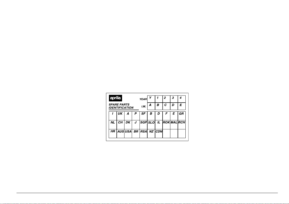
NOTE Soon after purchasing the vehi-
cle, write d own the id entificat ion data indicated on the SPARE PARTS IDENTIFICATION LABEL in the table here below. This
label is positioned on the left side of the
frame; to read it, it is necessary to remove
the rider saddle, see p. 76 (REMOVING
THE RIDER SADDLE).
These data indicate:
– YEAR = year of manufacture (Y, 1, 2, ...);
– I.M. = modification code (A, B, C, ...);
– COUN TRY CODES = homologation
country (I, UK, A, ...).
and are to be supplied to the aprilia Official Dealer as reference data for the purchase of spare parts or specific accessories of the model you have acquired.
In this manual the various versions are indicated by the following symb ols:
RSV mille
W
RSV mille R
w
automatic light switching version
e
(Automatic Switch-on Device)
optional
m
catalytic version
o
VERSION:
Italy
I
United Kingdom
U
Austria
a
Portugal
p
Finland
F
Belgium
B
Germany
d
France
f
Spain
E
Greece
G
Holland
O
Switzerland
Y
Denmark
D
Japan
J
S
s
i
¬
M
c
H
A
u
Ä
R
n
C
Singapore
Slovenia
Israel
South Korea
Malaysia
Chile
Croatia
Australia
United States
of America
Brazil
South Africa
New Zealand
Canada
use and maintenance RSV mille - RSV mille R
3
Page 4
4!",%/&#/.4%.43
SAFE DRIVE ...............................................................5
BASIC SAFETY RULES....................................... 6
CLOTHING ........................................................... 9
ACCESSORIES.................................................. 10
LOAD.................................................................. 10
ARRANGEMENT OF THE MAIN ELEMENTS
ARRANGEMENT OF THE MAIN ELEMENTS
ARRANGEMENT
OF THE INSTRUMENTS/CONTROLS .................... 16
INSTRUMENTS AND INDICATORS........................ 17
INSTRUMENTS AND INDICATORS TABLE...... 18
MULTIFUNCTION COMPUTER ......................... 20
MAIN INDEPENDENT CONTROLS......................... 26
CONTROLS ON THE LEFT PART
OF THE HANDLEBAR........................................ 26
CONTROLS ON THE RIGHT PART
OF THE HANDLEBAR........................................ 27
IGNITION SWITCH............................................. 28
STEERING LOCK............................................... 28
AUXILIARY EQUIPMENT........................................ 29
UNLOCKING/LOCKING
THE PASSENGER SEAT
UNLOCKING/LOCKING
THE GLOVE/TOOL KIT
COMPARTMENT COVER
GLOVE/TOOL KIT COMPARTMENT................. 31
LUGGAGE RACK FASTENINGS
SPECIAL TOOLS
ACCESSORIES.................................................. 32
NUMBER PLATE-HOLDER EXTENSION
MAIN COMPONENTS.............................................. 33
FUEL................................................................... 33
BRAKE FLUID - recommendations..................... 34
DISC BRAKES.......... ..... ..... ..... ...... ..... ..... ..... ...... 35
FRONT BRAKE .................................................. 36
REAR BRAKE..................................................... 37
CLUTCH FLUID - recommendations ............ ...... 38
CLUTCH ............................................................. 39
COOLANT........................................................... 40
TYRES................................................................ 42
ENGINE OIL ....................................................... 43
ADJUSTING
THE FRONT BRAKE CONTROL LEVER
AND THE CLUTCH CONTROL LEVER ............. 44
W
............................ 29
w
........................... 30
m
......................................... 32
W
................ 31
m
W
w
. 12
. 14
.... 32
ADJUSTING
THE REAR BRAKE CONTROL LEVER
CLEARANCE ..................................................... 44
ADJUSTING
THE REAR BRAKE CONTROL LEVER
AND THE GEAR LEVER ................................... 45
AUTOMATIC LIGHT SWITCHING
VERSION
EXHAUST SILENCER/EXHAUST TERMINAL.. 45
INSTRUCTIONS FOR USE..................................... 46
GETTING ON AND OFF THE VEHICLE ........... 46
PRELIMINARY CHECKING OPERATIONS ...... 48
PRELIMINARY CHECKING OPERATIONS ...... 49
STARTING......................................................... 50
DEPARTURE AND DRIVE ................................ 53
RUNNING-IN...................................................... 56
STOPPING......................................................... 57
PARKING........................................................... 57
POSITIONING THE VEHICLE ON THE STAND 58
SUGGESTIONS TO PREVENT THEFT ............ 58
MAINTENANCE ...................................................... 59
REGULAR SERVICE INTERVALS CHART....... 60
IDENTIFICATION DATA.... ...... ..... ..... ..... ...... ..... 62
CHECKING
THE ENGINE OIL LEVEL AND TOPPING UP .. 62
CHANGING
THE ENGINE OIL AND THE OIL FILTER ......... 64
AIR CLEANER ................................................... 66
ASSEMBLING THE PINS
FOR THE REAR SUPPORT STAND
POSITIONING THE VEHICLE
ON THE REAR SUPPORT STAND
POSITIONING THE VEHICLE
ON THE FRONT SUPPORT STAND
FRONT WHEEL................................................. 68
FRONT BRAKE CALIPERS............................... 70
REAR WHEEL ................................................... 71
DRIVE CHAIN.................................................... 74
REMOVING THE RIDER SADDLE.................... 76
LIFTING THE FUEL TANK ................................ 76
REMOVING THE SIDE FAIRINGS .................... 77
REMOVING THE LOWER FAIRING.................. 77
REMOVING THE SIDE COVERS...................... 78
REMOVING THE REAR-VIEW MIRRORS........ 78
REMOVING THE FRONT PART
OF THE FAIRING .............................................. 79
e
..................................................... 45
m
.......... 67
m
............. 67
m
.......... 67
REMOVING THE SIDE STAND......................... 80
INSPECTING THE FRONT
AND REAR SUSPENSIONS.............................. 82
FRONT SUSPENSION ...................................... 82
STEERING DAMPER......................................... 85
REAR SUSPENSION......................................... 86
CHECKING THE BRAKE PAD WEAR............... 88
ADJUSTING
THE COLD START CONTROL (
IDLING ADJUSTMENT ........................... ..... ..... . 89
ADJUSTING THE ACCELERATOR CONTROL 89
SPARK PLUGS.................................................. 90
CHECKING THE SIDE STAND.......................... 92
BATTERY........................................................... 93
CHECKING AND CLEANING THE TERMINALS 93
REMOVING THE BATTERY.............................. 94
CHECKING THE ELECTROLYTE LEVEL......... 95
RECHARGING THE BATTERY ......................... 95
INSTALLING THE BATTERY............................. 96
LONG INACTIVITY OF THE BATTERY............. 97
CHECKING THE SWITCHES ............................ 97
CHANGING THE FUSES................................... 98
ADJUSTING
THE VERTICAL HEADLIGHT BEAM............... 100
BULBS..................... ...... ..... ..... ..... ...... ..... ......... 101
CHANGING THE DASHBOARD BULBS ......... 101
CHANGING THE HEADLIGHT BULBS ........... 102
CHANGING THE FRONT
AND REAR DIRECTION INDICATOR BULBS 104
CHANGING THE REAR LIGHT BULB............. 105
TRANSPORT. ..... ..... ..... ...... ............................... .... 106
CLEANING ......................... ..... .............................. 106
LONG PERIODS OF INACTIVITY................... 108
TECHNICAL DATA ............ ..... ..... ..... ...... ..... ..... .... 109
LUBRICANT CHART........................................ 113
Importers ................................................... 116-117
WIRING DIAGRAM -
RSV mille - RSV mille R................................... 118
WIRING DIAGRAM RSV mille
e
- RSV mille R e...................... 120
0
).................... 89
use and maintenance RSV mille - RSV mille R
4
Page 5
Page 6
"!3)#3!&%4925,%3
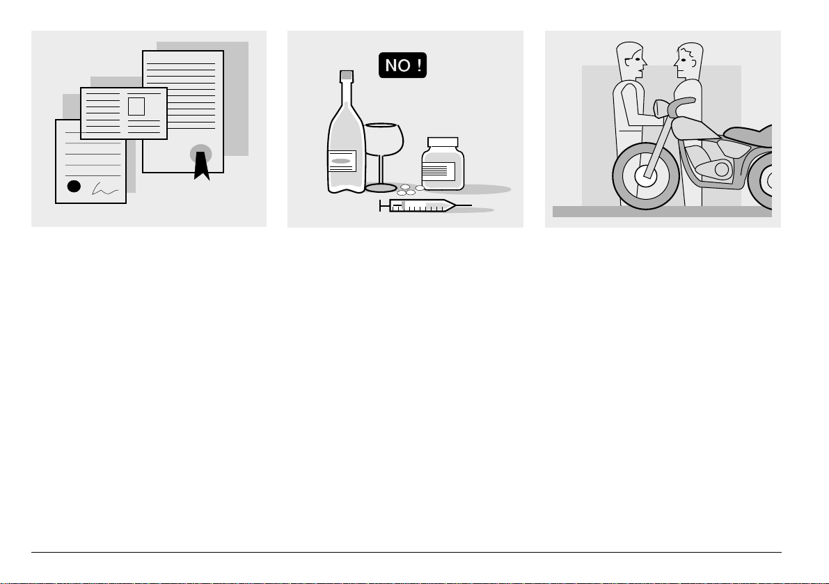
To drive the vehicle it is necessary to be in
possession of all the r equirements prescribed by law (driving licence, minimum
age, psychophysical ability, insurance,
state taxes, vehic le registration, n umber
plate, etc.).
Gradually get to know the vehicle by driving it first in areas with low tra ffic and/or pri vate areas.
use and maintenance RSV mille - RSV mille R
6
The use of medicins, alcohol and drugs or
psychotropic su bstanc es no tably incre ase s
the risk of accidents.
Be sure that yo u are in go od psyc hophy sical conditions and f it for driving and pay
particular attention to physical weariness
and drowsiness.
Most road accidents ar e caused by the
driver’s lack of experience.
NEVER lend the vehicle to beginners and,
in any case, make sure that the driver has
all the requirements for driving.
Page 7
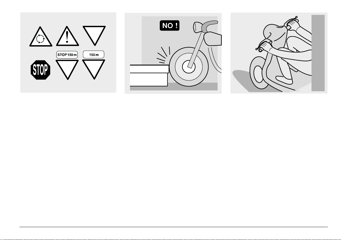
Rigorously observe all road signs and national and local road regulations.
Avoid abrupt movements that can be dangerous for yourself and other people (for
example: rearing up on the back wheel,
speeding, etc. ), and give d ue co nside ratio n
to the road surface, visibil ity and ot her driving conditions.
Avoid obstacles that could damage the vehicle or make you lose control.
Avoid riding in the slipstream created by
preceding vehicles in order to increase
your speed.
Always drive with both hands on the handlebars and both feet on the footrests (or
on the ride r’s footboar ds), in the cor rect
driving posture.
Avoid standing up or stretching your limbs
while driving.
use and maintenance RSV mille - RSV mille R
7
Page 8
OIL
COOLER
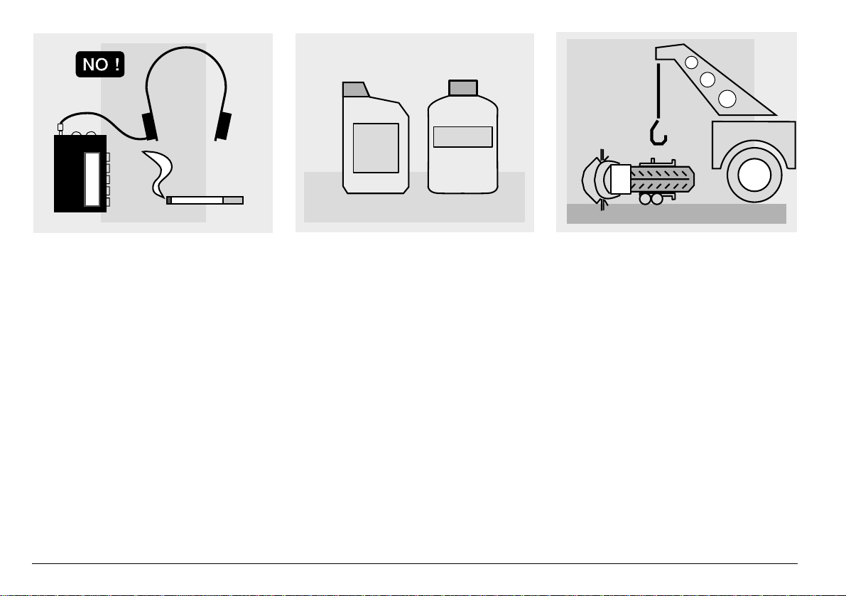
The driver should pay attention and avoid
distractions caused by people, things and
movements (never smok e, eat, drink , read,
etc.) while driving.
use and maintenance RSV mille - RSV mille R
8
Use only the veh ic le’s specific fuels and lubricants indicated in the "LUBRICANT
CHART"; check a ll oil , f uel an d c oolant levels regularly.
If the vehicle has been involved in an accident, make sure that no damage has occurred to the control levers, pipes, wires,
braking system and vital parts.
If necessary, have the ve hicle ins pecte d by
an aprilia Official Dealer who should carefully check the frame, handlebars, suspensions, safety parts an d all the de vices that
you cannot check by yourself.
Always remember to report any malfunction to the technicians to help them in their
work.
Never use the vehicle when the amount of
damage it has suffered endangers your
safety.
Page 9
ONLY ORIGINALS
A12
345
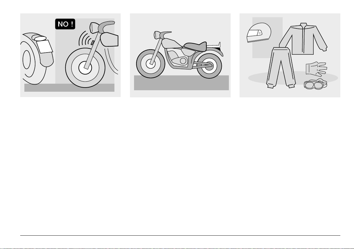
Never change the position, inclination or
colour of: number plate, direction indicators, lights and horns.
Any modification of the vehi cle will result in
the invalidity of the guarantee
Any modification of the vehicle and/or the
removal of original components can compromise vehicle performance levels and
safety or even make it illegal.
We recommend respecting all regulations
and national an d l oc al pro vi si ons regarding
the equipment of the vehicle.
In particular, avoid all modifications that increase the vehi cle’s per formance levels or
alter its original characteristics.
Never race with other vehicles.
Avoid off-road driving.
#,/4().'
Before starting, always wear a correctly
fastened crash helmet. Make sure that it is
homologated, in good shape, of the right
size and that the visor is clean.
Wear protective clothing, preferably in light
and/or reflecting colours. In this way you
will make yourself more visible to the other
drivers, thus notably reducin g the risk of
being knocked down, and you will be more
protected in case of fall.
This clothing should be very tight-fitting
and fastened at the wrists and ankles;
strings, belts and ties should not be hanging loose; prevent these and other objects
from interfering with driving by getting entangled with moving parts or driving mechanisms.
use and maintenance RSV mille - RSV mille R
9
Page 10
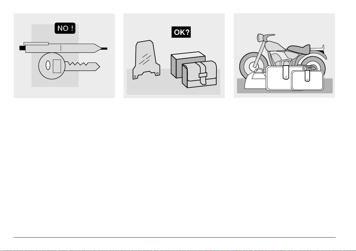
Do not keep objects tha t can be dan gerous
in case of fall, for example pointed objects
like keys, pens, glass vials etc. in your
pockets (the same recommendations also
apply to passengers).
use and maintenance RSV mille - RSV mille R
10
!##%33/2)%3
The owner of the vehicle is responsible for
the choice, installation and use of any accessory.
Avoid installing accessories that cover
horns or lights or that could impair their
functions, limit the suspension stroke and
the steering ang le, h amper the o peratio n of
the controls and reduce the distance from
the ground and the angle of inclination in
turns.
Avoid using accessories that hamper access to the co n tro l s, sinc e t h is can pr ol on g
reaction times during an emergency.
Big fairings and windshiel ds installed on
the vehicle may p roduce aerodyna mic forces that affect the sta bility of the v ehic le, especially when riding at high speed.
Make sure that the equipment is well fastened to the vehicle and not dangerous
during driving.
Do not install electrical devices and do not
modify those alread y existing to av oid electrical over load s, b ecau se t he v ehic le c ould
suddenly stop or there could be a dangerous current sh ort a ge in th e hor n an d in t he
lights.
aprilia recommends the use of genuine
accessories (aprilia genuine accessories).
,/!$
Be careful and moderate when loading
your luggage. Kee p any luggage loaded as
close as possible to t he center of gravity of
the vehicle and distribute the load uniformly on both sides, in order to reduce umbalance to the minimum. Furthermore, make
sure that the load is firmly secured to the
vehicle, especially during long trips.
Avoid hanging b ulky , h eav y an d/or danger-
Page 11
KG!
ous objects on the handlebars, mudguards
and forks, because the vehicle might respond more slowly in turns and its manoeuvrability could be una voidably impaired.
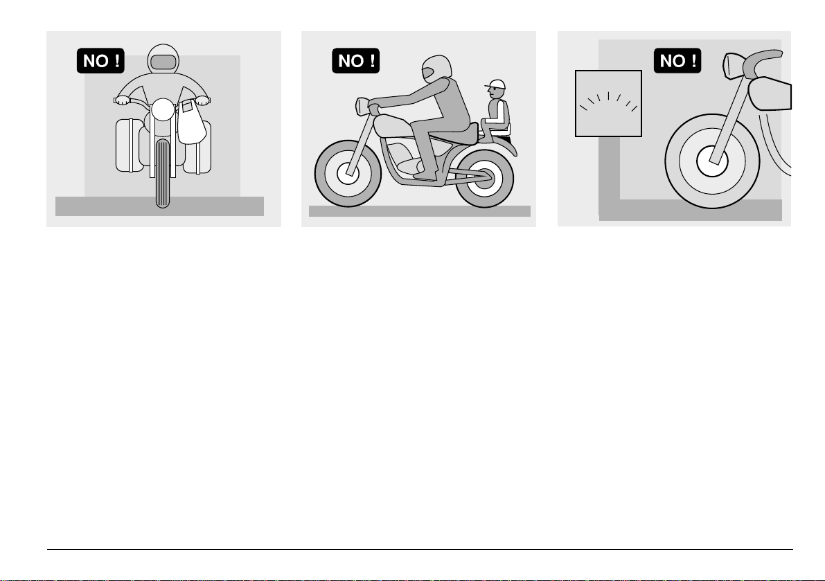
Do not place bags th at a re too bulky on the
vehicle sides and do not ride with the crash
helmet, because they could hit people or
obstacles, making you lose control of the
vehicle.
Do not carry any bag if it is not tightly secured to the vehicle.
Do not carry bags which protrude too m uch
from the luggage- rack or which cover the
lights, horn or indicators.
Do not carry animals or children on the
glove compartment or on the luggage rack .
Do not exceed the maximum load allowed
for each side-bag.
When the vehicle is overlo ade d, its s tabili ty
and its manoeuvrability can be compromised.
use and maintenance RSV mille - RSV mille R
11
Page 12
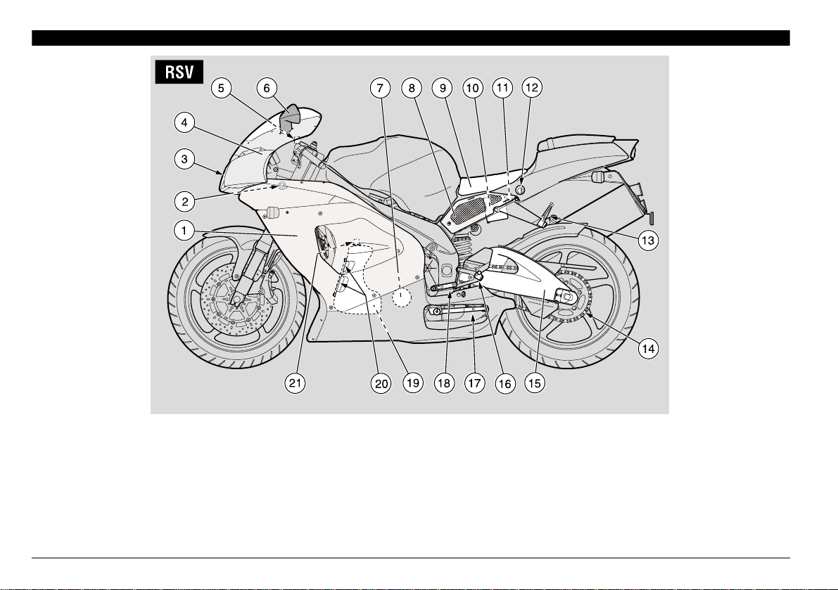
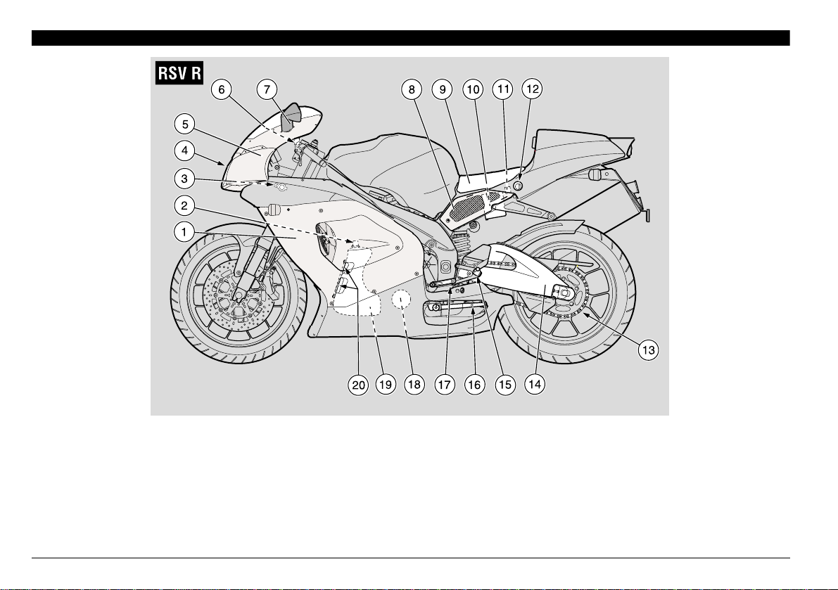
!22!.'%-%.4/& 4(% -!). %,%-%.43W
+%9
1) Left fairing
2) Non-adjustable steering
damper (adjustable steering
damper W m)
3) Headlight
4) Front part of the fairing
5) Clutch fluid reservo ir
6) Left rear-view mirror
7) Engine oil filter
8) Left side cover
9) Rider saddle
10) Battery
11) Main fuse carrier (30 A)
12) Passenger seat lock
13) Passenger left foot rest
(snapping, closed/open)
14) Drive chain
15) Rear fork
16) Rider left footrest
17) Side stand
18) Shifting lever
19) Engine oil tank
20) Engine oil level
21) Engine oil tank cap
use and maintenance RSV mille - RSV mille R
12
Page 13
+%9
1) Rear shoc k absorber
2) Passenger right footrest
(snapping, closed/open)
3) Rear light
4) Glove/tool kit compartment
5) Passenger seat (glo ve /too l k it
compartment cover W m)
6) Passenger grab strap
7) Electronic unit
8) Right side cover
9) Fuel tank
10) Coolant expansion tank cap
11) Fuel tank filler cap
12) Air cleaner
13) Right rear-view mirror
14) Front br ake fluid tank
15) Secondary fuse carrier
(15 A)
16) Horn
17) Expansion tank
18) Rear brake fluid tank
19) Lower fairing
20) Rear brake pump
21) Rear brake control lever
22) Rider right footrest
use and maintenance RSV mille - RSV mille R
13
Page 14
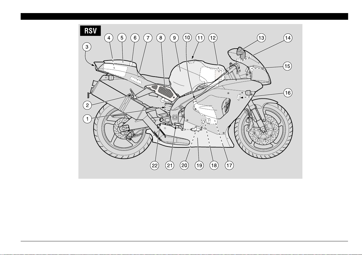
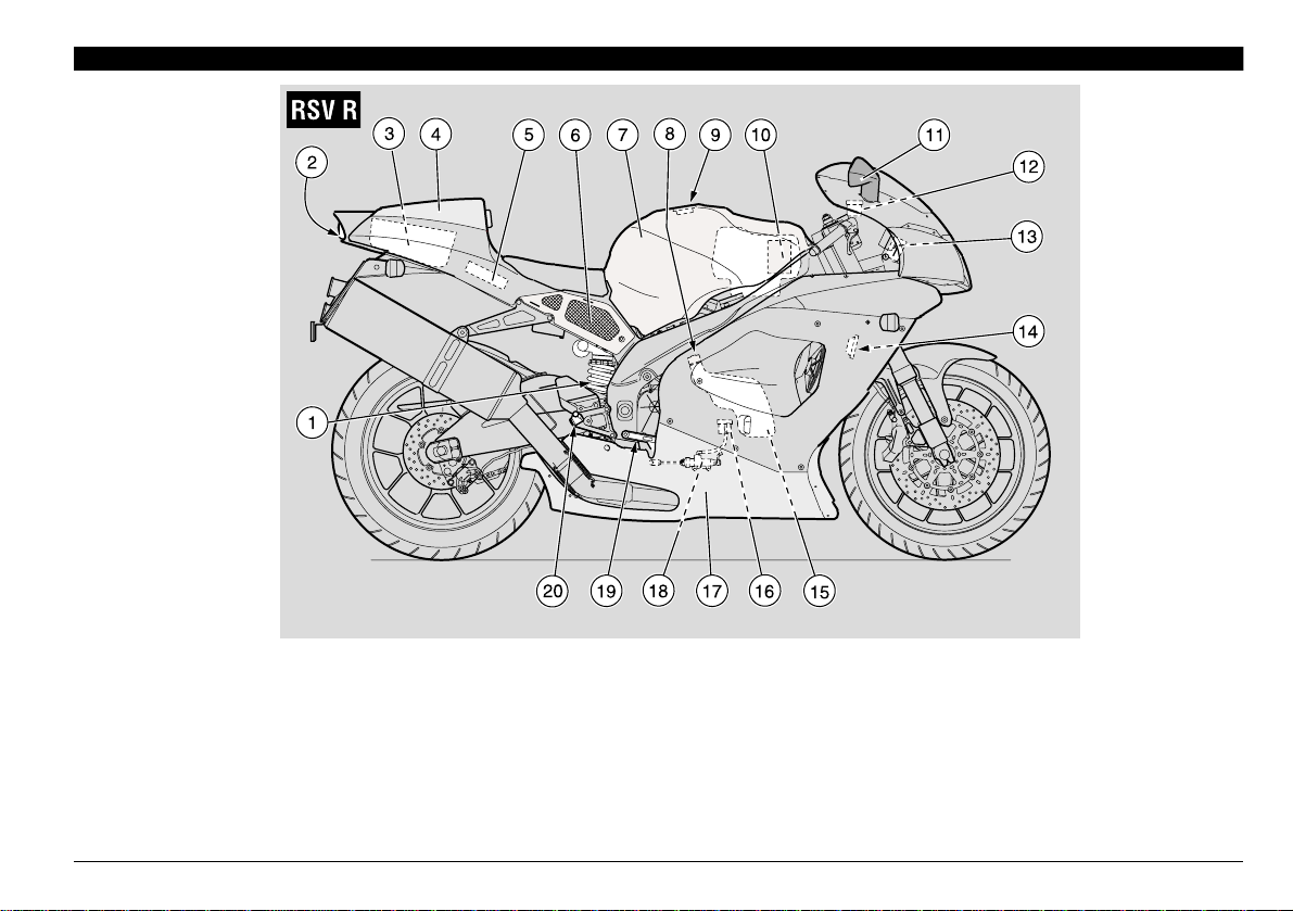
!22!.'%-%.4/& 4(% -!). %,%-%.43w
+%9
1) Left fairing
2) Engine oil tank cap
3) Adjustable steering damper
4) Headlight
5) Front part of the fairing
6) Clutch fluid reservoir
8) Left side cover
9) Rider saddle
10) Battery
11) Main fuse carrier (30A)
12) Glove/tool kit compa rtment
lock
7) Left rear-view mirror
13) Drive chain
14) Rear fork
15) Rider left footrest
16) Side stand
17) Shifting lever
18) Engine oil filter
19) Engine oil tank
20) Engine oil level
use and maintenance RSV mille - RSV mille R
14
Page 15
+%9
1) Rear shock absorber
2) Rear light
3) Glove/tool kit compartment
4) Glove/tool kit compartment
cover
5) Electronic unit
6) Right side cover
7) Fuel tank
8) Coolant expansion tank
cap
9) Fuel tank filler cap
10) Air cleaner
11) Right rear-view mirror
12) Front brake fluid tank
13) Secondary fuse carrier
(15A)
14) Horn
15) Expansion tank
16) Rear brake fluid tank
17) Lower fairing
18) Rear brake pump
19) Rear brake control lever
20) Rider right footrest
use and maintenance RSV mille - RSV mille R
15
Page 16
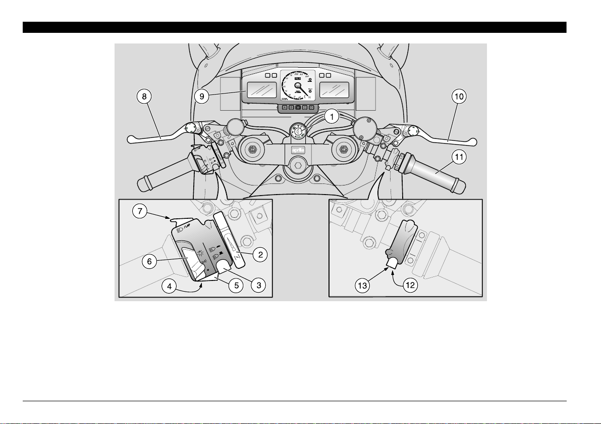
!22!.'%-%.4/& 4(% ).3425-%.43#/.42/,3
+%9
1) Ignition switch/steering lock (2 - 1 - &)
2) Cold start lever (0)
3) Dimmer switch (8 - 7)
4) Direction indicator switch (6)
5) Horn push button (*)
6) Light switch (( - ' -
7) High beam signaller push button (7)/LAP push button (multifunction)
use and maintenance RSV mille - RSV mille R
16
) (not provided for e)
•
8) Clutch lever
9) Instruments and indicators
10) Front brake lever
11) Throttle grip
12) Start push button (+)
13) Engine stop switch (#2 - !1)
Page 17
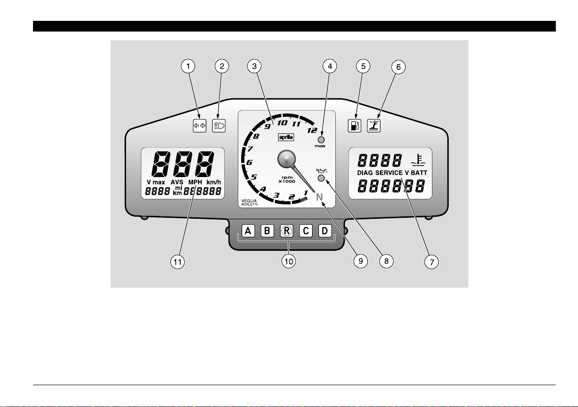
).3425-%.43!.$ ).$)#!4/23
+%9
1) Green direction indicator warning light (6)
2) Blue high beam warning light (7)
3) Revolution counter
4) Programmable red line warning light LED (max)
5) Amber low fuel warning light (-)
6) Amber “side stand down” warning light (Æ)
7) Right multifunction digital display (coolant temperature - clock
- battery voltage - chronometer - diagnostic)
8) Red engine oil pressure warning light LED (.)
9) Green neutral indicator warning light (/)
10) Multifunction co mp uter prog ram mi ng pus h butt ons
11) Left multifunction digital display (speedometer - odometer)
use and maintenance RSV mille - RSV mille R
17
Page 18
).3425-%.43!.$).$)#!4/234!",%
Description Function
Direction indicator warning light
High beam warning light
Revolution counter rpm
Red line warning light LED max
Low fuel warning light
Side stand down warning light
Engine oil pressure warning light
LED
Neutral indicator warning light
Multifunction
digital display
(left side)
Speedometer (km/h - MPH)
Odometer (km - mi) Indicates the partial or total number of kilometres or miles covered.
6 Blinks when the direction indicators are on.
7 Comes on when the high beam bulbs are on or when the headlight signaller is operated.
Indicates the number of revolutions of the engine per minute.
aCAUTION
Blinks when the max. rpm set by the user is reached, see p. 22 [SETTING TH E RED LINE
THRESHOLD (WITH ENGINE OFF ONLY)].
It comes on when the engine max. rpm threshold setting is confirmed, see p. 22 [SETTING THE
RED LINE THRESHOLD (WITH ENGINE OFF ONLY)] and whenever the ignition key is rotated
to position “
Comes on when the qu ant it y of fu el left in the tan k is about 4.5 ± 1 L.
-
In this case, top up as soon as possible, see p. 33 (FUEL).
Comes on when the side stand is down.
Æ
Comes on whenever the ignition switch is in position “2” and the engine is not running, thus
checking the functionality of the LED.
If the light LED does not co m e on in this phase, contact an aprilia Official Dealer.
.
aCAUTION
this means that the engine oil pressure in the circuit is insufficient.
In this case, stop the engin e imm ediately and contact an
Comes on when the ge ar is in neut ra l .
/
Indicates the instantaneous, average or maximum driving speed (in kilometres or miles) according to the pr e setting, see p. 20 (MULTIFUNCTION COMPUTER).
Never exceed the engine max. speed rate, see p. 56 (RUNNINGIN).
2”, for about three seconds, see p. 20 (MULTIFUNCTION COMPUTER).
If the engine oil pressure warning light LED “
the start or comes on during the normal op eration of the eng ine,
APRILIA
.” remains on after
Official Dealer.
To alternate the
data displayed,
see p. 20 (MULTIFUNCTION
COMPUTER).
use and maintenance RSV mille - RSV mille R
18
Page 19

Description Function
Indicates the temperatu re of the coolant in the engine, see p. 20 (MULTIFUNCTION COMPUTER).
aCAUTION
of the coolan t te mper at ur e; in th is case th er e woul d be a fu rt her te mp er ature increase.
If a temperature of 115 – 120 °C (2 39 – 248 °F) is displ ayed, stop t he engine,
turn the ignition key to position “
Coolant temperature (°C/°F)
Multifunction
digital display
(right side)
ing fans.
At this point turn the ignitio n key to p osition “
)
see p. 40 (COOLANT).
If the writing "///" is displayed, stop the vehicle an d let the engine run at
3000 rpm for approx ima tel y two min utes , th us all owin g th e cool ant to circ ulat e
regularly in the system; then press the engine stop switch to pos ition "
and check the coolant level, see p. 40 (COOLANT). If the writing “
still displayed after the coolant level has been checked, contact an aprilia Official Dealer.
aCAUTION
ly damaged.
Do not leave the ignition switch in position “
since the cooling fans would stop indepe ndently
1”,
2” and wait for the discon nection of the cool-
1” and check the co olant level ,
! 1"
///” is
If the maximum allowed temperature (120°C 248 °F) is exceeded, the engine ma y be serious-
To alternate the
data displayed,
see p. 20 (MULTIFUNCTION
COMPUTER).
Clock
Battery v olt age V
BATT
Chronometer
Diagnostics
Indicates the hour and minutes according to the presetting, see p. 20 (MULTIFUNCTION COMPUTER).
Indicates the battery voltage, see p. 20 (MULTIFUNCTION COMPUTER).
Indicates the various timings according to the presetting, see p. 20 (MULTIFUNCTION COMPUTER).
Whenever the ignition switch is brought to posi t ion “2”, the writing "HIL" appears on the right
side of the multifunctio n di splay for approximate ly th ree seconds.
aCAUTION
anomaly. In many cases, the engine keeps running with reduced performance levels; immediately co ntact an
If the writing “
the engine, this means that the electronic unit has detected an
APRILIA
Official Dealer.
(),” is displayed during the normal operation of
use and maintenance RSV mille - RSV mille R
19
Page 20

12
5
8
-5,4)&5.#4)/.#/-054%2
When the ignition key (1) is rota ted to p osi tion “2”, the following warning lights come
on on the dashboard:
– red line warning light LED “max” (2);
– red engine oil pressure warning light
LED “.” (3), which remains on until the
engine starts.
The pointer (4) of the revolution counter
shifts to the maximu m value (rpm) set by
the user. After about three seconds the
red line warning light LED "max" (2) goes
off; the pointer (4) of the revolution counter
returns to its initial position.
The writing "
side of the multifunction display for three
seconds.
In this way the component operati on is
tested.
()," (5) appears on the right
aCAUTION
After the first 1000 km (625 mi) and suc-
use and maintenance RSV mille - RSV mille R
20
9
AVSVmax
mi
km
13a
10
cessively every 750 0 km (4687 mi), t he
writing “SERVICE” (5a) a ppears on the
right display.
In this case contact an APRILIA Official
Dealer, who will ca rry out the operations indicated in the regular service intervals chart, see p. 60 (REGULAR
SERVICE INTERVALS CHART). To
make the writing “SERVICE” disappear,
press the “LAP” push button (6) and
then the push button r and keep them
pressed for about five seconds.
With the ignition key (1) in position "2" the
standard settings o n the dashb oard are the
following:
Right display: Clock (7), c oolant temp erature in °C (8).
Left display: Instantaneous speed in
km/h (9), trip 1 (trip odometer) (10), total
kilometres/miles odometer (11).
Upon installati on of the battery or of the
30A main fuses:
km/hMPH
11
5a
DIAG
– the revolution counter pointer (4) makes
twelve clockwise clicks, thus checking the
operation of the revolution counter itself;
– the instantaneous, maximum an d aver-
age speed function is set in “km/h”;
– the coolant temperature is set in °C;
– the digital clock is set to zero;
– the red line is set at 6000 rpm, indicated
by the coming on of the red line warning
light LED “max ” (red) (2).
SERVICE
7
V BATT
13
NOTE If necessary, carry out the appro-
priate adjustments.
SEGMENT OPERATION CHECK
◆ Press the push buttons l and k at the
same time.
◆ Rotate the ignition key (1) from position
“1” to position “2”.
All the segments (13) (13a) will remain on
until the push buttons l and k are released.
SWITCHING FROM km TO mi (from
km/h to MPH) AND VICEVERSA (LEFT
DISPLAY)
Page 21

9
14
16
AVSVmax
km/hMPH
mi
km
10
◆ Press the push button l until, after
about five seconds, all the writings (12)
on the left display start blinking.
◆ Release the push button l.
◆ Press the push button k to change the
unit of measurement from “km” to “mi”
(from “km/h” to “MPH”) or viceversa.
◆ To confirm the setting, press the push
button l for about five seconds.
SETTING THE INSTANTANEOUS,
MAXIMUM AND AVERAGE SPEED
(LEFT DISPLAY)
NOTE Two seconds after the vehicle
has started moving, the instant aneous
speed is automatically shown on the display, even if a different function is set.
When the igni t i on k ey i s ro t at ed t o po si tio n
“2”, the instantaneous speed (9) and the
partial number of kilometres/miles covered
“trip 1” (10) appear on the left display.
Resetting “trip 1” (10): with the odometer set
on the instantaneous speed function, press
15
AVSVmax
km/hMPH
mi
km
10
the push button r for about two seconds.
◆ To display the maximum speed (14) and
the distance “trip 1” (10), press the push
button k for about one second. The
writing “V max” (15), the maximum
speed (14) and the distance “trip 1” (10)
are displayed.
Resetting the maximum speed (14): with
the odometer set on the “V max” function,
press the push button r for abo ut 2 seconds.
NOTE The measurement of the maxi-
mum speed is relevant to the distance covered from the last setting to zero of the maximum speed itself. The distance “trip 1” (10)
shown on the display indicates the number
of kilometres/miles covered from the last
setting to zero, to the distance “trip 1”.
◆ To display the average speed (16) and
the distance “trip 2” (17), press the push
button k again for about 1 second.
AVSVmax
km/hMPH
mi
km
17
The writin g “AVS” (18), the average speed
(16) and the distance “trip 2” (17) are displayed.
Resetting the average speed (16) and the
distance “trip 2 ” (1 7): w ith t he od om ete r s et
on the “AVS” function, press the push but-
ton r for about 1 second.
18
NOTE The measurement of the av erage
speed is relevant to th e distance “trip 2 ”
(odometer).
The distance “trip 2 ” (1 7) s ho w n on the di splay indicates the number of kil ometres/miles covered from the last setting to
zero.
If more than 1000 km (625 mi) are covered
without setting “trip 2” to zero, the value of
the average speed will be wrong.
◆ To display the instantaneous speed (13)
and the distance “trip 1” (10), press the
push button k again.
use and maintenance RSV mille - RSV mille R
21
Page 22

SETTING THE RED LINE THRESHOLD
(WITH ENGINE OFF ONLY)
When the maximum rpm set is exceeded, the red line warning lig ht LED “max”
(2) positioned on the dashboard starts
blinking.
If the push button j is pressed fo r less
than one second, the pointer of the revolution counter (4) shifts to the red line value
set for three seconds, after which it returns
to its initial position.
use and maintenance RSV mille - RSV mille R
22
For the adjustment, proceed as follows:
◆ Press the push button j, release it and
press it j again within 3 seconds. The
pointer (4) moves increasing the value
by 1000 rpm at each click, as long as j
is kept pressed; when it has reached the
maximum value, it starts again from the
beginning.
◆ Press the push button j until the de-
sired rpm value has been set.
◆ If the push button j is released and th en
pressed again within 3 s econ ds, in termittently, the po inter (4) moves incr easing
the value by 100 rpm at eac h cl ic k; wh en
it has reached the maxi mum value, it
starts again from the beginning.
NOTE It is not possible to set the red
line at values lower than 2000 rpm or higher than 120 00 rpm.
aCAUTION
Never exceed the recommended rpm,
see p. 56 (RUNNING-IN).
◆ To confirm, release the push button j.
After three seconds, the red line threshold setting is stored.
NOTE The setting is confirmed by the
coming on of the red l ine w ar nin g l ig ht LED
“max” (2).
Page 23

MULTIFUNCTION (RIGHT DISPLAY)
The right display (multifunction) includes
the coolant te mperature in °C (°F) (8) and
the digital clock (7) as standard settings.
NOTE When the engine is c ol d, the writ-
ing "9" blinks.
By pressing the push button g, the follow-
ing functions can be obtained in sequence:
8
SERVICEDIAG V BATT
SERVICEDIAG V BATT
20
Standard setting: Temperature in °C
and digital clock
g
Battery voltage (V BATT)
g
Setting the hour
g
Setting the minutes
g
Setting °C or °F
7
STANDARD SETTING: COOLANT TEMPERATURE AND DIGITAL CLOCK
The coolant temperature value (8) is
shown in the upper pa rt of the r ight di splay .
It is possible to switch from °C to °F and
viceversa, see p. 24 (SETTING °C OR °F).
– When the temperature is bel ow 35°C
(95°F), the writing “9” (8) blinks on
the right display.
– When th e temperature is over 11 5°C
(239°F), the value ( 8) bli nks on th e right
display, even if a function different from
the standard sett ing ha s bee n set.
– When th e temperature is over 13 0°C
(266°F), the writin g “
on the right display.
///” (8) appears
aCAUTION
If the writing “///” is displayed with a
temperature below 130°C (266°F), there
may be a failure of the electric circuit. In
this case, con tact an APRILIA Official
Dealer.
19
Thermometer range on the display: 35–
130°C (95–266 °F).
The digital clock (7) appe ars in the lowe r
part of the right display. To set or modify
hour and minutes, see p. 24 (SETTING
THE HOUR) and (SETTING THE MINUTES).
BATTERY VOLTAGE - VBATT
◆ If the push button g is pressed once, the
battery voltage expre ssed in vo lt (19) appears in the lower part of the right display, while the coolant temperatu re (8) is
displayed in the upper part. The writing
“V BATT” (20) is displayed. The recharge circuit functions correctly if at
4000 rpm the battery voltage with low
beam on is included between 13 and 15
V.
use and maintenance RSV mille - RSV mille R
23
Page 24

SERVICEDIAG V BATT
21 22
8
SERVICEDIAG V BATT
SETTING THE HOUR
◆ When the push button g is pressed for
the second time, the hour segments (21)
start blinking in the lower part of the right
display (digital clock).
◆ To modify the hour setting, press the
“LAP” push button (6) on the left part of
the handlebar.
◆ To confirm the hour setting, press the
push button g.
use and maintenance RSV mille - RSV mille R
24
SETTING THE MINUTES
◆ When the push button g is pressed for
the third time, the minute segments (22)
start blinking in the lower part of the right
display (digital clock) .
◆ To modify the minute setting, press the
“LAP” push button (6) on the left part of
the handlebar.
◆ To confirm the minute setting, press the
push button g.
SETTING °C OR °F
◆ When the push button g is pressed for
the fourth time, the segm ents o f the c oolant temperature in °C or °F (8) start
blinking in the upper part of the display.
◆ To modify from °C to °F setting, or vice
versa, press the “LAP” push button (6)
on the left part of the handlebar.
◆ To confirm the setting, press the push
button g.
Page 25

26
SERVICEDIAG V BATT
8
SERVICEDIAG V BATT
CHRONOMETER (RIGHT DISPLAY)
The chrono meter makes it po ssible to
measure the time per lap with the vehicle
on a racetrack and to store the data, in
such a way as to be able to consult them
successively.
When the “CHRONOMETER” function has
been selected, it is not possible to recall
the following functions:
– maximum speed “V max”;
– average speed “AVS”;
– distance “trip 2”.
◆ To operate the chronometer, press the
“LAP” push button (6) and, within seven
seconds, the push button g.
◆ To start timing, press the “LAP” push
button (6) and release it immediately.
◆ To store the time acquired, press the
“LAP” push button (6).
23
The “LAP” push button (6) is not enabled
for 10 seconds and the last time stored
(23) is shown on the display.
After which, the chronometer with the current timing (24) is displayed, starting from
ten seconds.
◆ To display the first time stored (25),
press the push button k.
◆ To be able to see the stored times in se-
quence, press the “LAP” push button (6).
The writings
(26) are displayed.
◆ To start timing again, press the push but-
ton k.
/, / , /, / , etc.
2524
NOTE It is possible to store max. 40
times, after which the “LAP” push button
(6) is not effective any longer.
◆ To set the memory to zero, press the
push button l and the “LAP” push button (6) at the same time for two seconds.
◆ To leave the chronometer function, press
7
the “LAP” push button (6) an d the push
button g.
The coolant temperature (8) and the digital
clock (7) appear on the right display (multifunction).
NOTE When the engine is c ol d, the writ-
ing "9" blinks.
DIAGNOSTICS
Whenever the ignition switch is turned to
position “2”, th e writing “
for about three seconds.
(),” is displayed
aCAUTION
If the writing “HIL” is displayed during
the normal operation of the engine, this
means that the electronic unit has detected an anomaly.
In many cases, the eng ine keeps running with reduced performance levels;
immediately contact an APRILIA Official
Dealer.
use and maintenance RSV mille - RSV mille R
25
Page 26

-!).).$%0%.$%.4 #/.42/,3
PUSH
P
A
L
/
3) DIMMER SWITCH (% - $)
6
When the lig ht swi tch is in pos ition "(": if th e di mmer swit ch
is in position "$", the high beam co me s on ; w hi le i f it i s i n
position "%", the low beam comes on.
5
4
3
H
S
U
P
1
2
#/.42/,3/.4(%,%&40!24/&4(%
(!.$,%"!2
NOTE The electrical parts work only when the ignition switch
is in position “2”.
1) HORN PUSH BUTTON (*)
The horn is activated when the push button is pressed.
2) DIRECTION INDICATOR SWITCH (6)
To indicate the turn to the left, move the switch to the left; to
indicate the turn to the right, move the switch to the right.
To turn off the direction indicator, press the switch.
3) DIMMER SWITCH (% - $)
e
When it is in position “%” the parking lights, the dashb oard
light and the low beam are always on .
When it is in position “$”, the high beam comes on.
4) LIGHT SWITCH (( - ' -
) (not provided for e)
•
When the light switc h is in pos ition "•" , the l ights are off; when
the switch is in po sition " '", the pa rking ligh ts and t he dashboard light are on; when the switch is in position "(", the
parking lights, the dashboard light and the low beam are on.
The high beam c an be operated b y means of the dimmer
switch.
5) HIGH BEAM SIGNALLER PUSH BUTTON (7)/LAP PUSH
BUTTON (multifunction)
NOTE For the setting of the functions, see p. 20 (MULTI-
FUNCTION COMPUTER).
This push button makes it possible to use the high beam signaller in case of da nger or e mergen cy, o r displ ays the v arious
preset functions on the right multifunction display:
– hour and minutes;
– coolant temperature (°C or °F);
– chronometer.
use and maintenance RSV mille - RSV mille R
26
Page 27

The high beam blinking is operated by pressing the push but-
PUSH
PUSH
ton, independently of the position of the light switch (( - '
).
-
•
NOTE To disconnect the hi gh beam b linking, release th e push
button.
H
S
U
P
6) COLD START LEVER (0)
The starter for the cold start of the engine is operated by rotating the lever “0” downwards.
To disconnect th e starte r, move the lev er “0” to its initia l po sition.
#/.42/,3/.4(%2)'(40!24/&4(%
(!.$,%"!2
NOTE The electrical parts work only when the ignition switch
is in position “2”.
7) ENGINE STOP SWITCH (# 2 - ! 1)
aWARNING
Do not operate the engine stop switch "#2 - !1" in running conditions.
This is a safety or emergency switch.
When the switch is in position "# 2", it is possible to start
the engine; the engine can be stopped by moving the switch
to position "! 1".
aCAUTION
With stopped engine and ignitio n sw itch in pos ition "# 2",
the battery may discharge.
When the vehicle has come to rest, af ter stopping the engine, move the ignition switch to position “! 1”.
7
8
H
S
U
P
8) START PUSH BUTTON (+)
When the start push button “+” is pressed, the starter makes
the engine run. For the starting, see p. 50 (STARTING).
use and maintenance RSV mille - RSV mille R
27
Page 28

)'.)4)/.37)4#(
The ignition switch (1) is positioned on the
upper plate of the steering column.
NOTE The key operates the ignition
switch/steering lock, the fuel tank lock and
the glove/tool kit compartment lock.
Two keys are supplied t ogether with the
vehicle (one spare key).
NOTE Do not keep the spare key on the
vehicle.
34%%2).',/#+
aWARNING
Never turn the key to position “&” in
running conditions, in order to avoid
losing control of the vehicle.
OPERATION
To lock the steering:
◆ Turn the handlebar completely leftw ard s.
◆ Turn the key to position “1”.
◆ Press the key and rotate it to position “&”.
◆ Extract the key.
Position Function Key removal
Steering
lock
The steering is
locked. It is
neither possible to start
the engine,
nor to switch
on the
lights.
Neither the
engine, nor
the lights
can be
switched on.
The engine
and the
lights can be
switched on.
It is possible
to remove the
key.
It is possible
to remove the
key.
It is not possible to remove
the key.
use and maintenance RSV mille - RSV mille R
28
Page 29

!58),)!29%15)0-%.4
5.,/#+).',/#+).'4(%
0!33%.'%23%!4W
◆ Position the vehicle on the stand, see p.
58 (POSITIONING THE VEHICLE ON
THE STAND).
◆ Introduce the key (1) in the seat lock.
◆ Rotate the key (1) anticlockwise, lift and
withdraw the seat (2) from behind.
NOTE Before lowering and locking the
seat (2), make sure that you have not left
the key in the glove/tool kit compartment.
To lock the seat (2), procee d as follows:
◆ Introduce its front part under the pas sen -
ger grab strap (3).
◆ Position the seat and press it, making
the lock snap.
aWARNING
Before leaving, make sure that the seat
(2) is properly locked.
NOTE Upon request it is possible to
supply the glove/tool kit compartment cover m (4) to be us ed instead of th e passenger seat.
If the glove/tool kit compartment cover is
used, the passenger grab strap must be
folded and put inside the glove/tool kit
compartment: fo r the installation and removal, see p. 29 (UNLOCKING/LOCKING
THE PASSENGER SEAT W).
A useful compartment is available under
the glove/tool kit compartment cover; to
reach it, it is sufficient to release and remove the flap (5).
use and maintenance RSV mille - RSV mille R
29
Page 30

5.,/#+).',/#+).'4(%
',/6%4//,+)4#/-0!24-%.4
#/6%2w
◆ Position the vehicle on the stand, see p.
58 (POSITIONING THE VEHICLE ON
THE STAND).
◆ Introduce the key (1) in the lock.
◆ T urn the ke y (1 ) a nt icl oc kwi se , r ais e a nd
withdraw the glove/tool kit compartment
cover (2) from behind.
use and maintenance RSV mille - RSV mille R
30
A useful compartment is available under
the glove/tool kit compartment cover; to
reach it, it is sufficient to release and remove the flap (3).
NOTE Before lowering and locking the
glove/tool kit compartment cover (2), make
sure that you have not left the key in the
glove/tool kit compartment.
To lock the glove/too l kit compartment
cover (2):
◆ Introduce the lower front projections in
the relevant recesses on the rear part of
the fairing.
◆ Position the glove/tool kit compartment
cover in its seat and press it, so that the
lock snaps.
aWARNING
Before leaving, make sure that the
glove/tool kit compartment cover (2) is
correctly locked.
Page 31

',/6%4//,+)4#/-0!24-%.4
To reach the glove/to ol kit compartment, proceed as follows:
ú Remove the passenger seat (or the
glove/tool kit compartment cover m),
see p. 29 (UNLOCKING/LOCKING THE
PASSENGER SEAT W).
÷ Remove the glove/tool kit compart-
ment cover, see p. 30 (UNLOCKING/LOCKING THE GLOVE/TOOL KIT
COMPARTMENT COVER w).
The tool kit (1) includes:
– 3, 4, 5, 6 mm ben t hexagon spanners
(2);
– 8 – 10 mm double fork spanner (3);
– 11 – 13 mm double fork spanner (4);
– 22 mm simple box spanner (5);
– 32 mm simple box spanner (6);
– extension for simple box spanners (7);
– 6 – 7 mm double socket spanner (8);
– 8 – 10 mm double socket spanner (9);
,5''!'%2!#+&!34%.).'3W
Small luggage c an b e an chored to the passenger seat, by means of elastic bands
that must be fixed to the two fastenings
(13).
Maximum allowed weight: 9 kg.
aWARNING
The luggage must have reduced dimensions and must be anchored securely.
– 16 mm socket spanner for spark plug
(10);
– double-ended, cross- /cut-he aded scr ew-
driver (11);
– tool case (12).
Maximum allowed weight: 1.5 kg.
use and maintenance RSV mille - RSV mille R
31
Page 32

30%#)!,4//,3m
To perform some specific operations, it is
advisable to use the following special tools
(to be requested to an aprilia Official Deal-
er):
Tool Operations Page
Pins (1) for
the rear
support
stand
Rear support
stand (2)
Front
support
stand (3).
To position the
vehicle on the rear
support stand.
Engine oil and
engine oil filter
change.
Rear wheel
disassembly.
Drive chain
adjustment.
Removal of the low er
fairing.
Front wheel
disassembly. 64
62
60
66
69
71
.5-"%20,!4%(/,$%2
%84%.3)/.m
The number plate-holder extension (4) can
be used when t he road surfac e is wet, in
fact it reduces the reach of the water spray
caused by the rear wheel.
NOTE The number plate-holder exten-
sion (4) is supplied as stand ard com ponen t
in the countries where this is required for
the homologation.
!##%33/2)%3
The following accessories:
–“R” front fork;
–“R” rear shock absorber;
– adjustable steering damper;
supplied as standard equipment with the
RSV mille R, can be installed also on the
RSV mille (contact an aprilia Official Deal-
er).
use and maintenance RSV mille - RSV mille R
32
Page 33

-!).#/-0/.%.43
&5%,
aWARNING
The fuel used for intern al combustion
engines is extremely inflammable and
in particular conditions it can become
explosive.
It is important to carry out the refuelling
and the maintenance operations in a
well-ventilated area, w ith the engine off.
Do not smoke while refuellin g or near
fuel vapours, in any case avoi d any contact with naked fla mes, spa rks and an y
other heat source to prevent the fuel
from catching fire or from exploding.
Further, prevent fuel from flowing out of
the fuel filler, as it could catch fi r e when
getting in contact w ith the red-hot surfaces of the engine.
In case some fuel has accidentally been
spilt, make sure that the area has completely dried and before starting the vehicle verify that there is no fuel inside
the fuel filler neck.
Since petrol expands under the heat of
the sun and due to the effects of sun radiation, never fill the tank to the brim.
Screw the plug up carefully after refuelling. Avoid any contact of the fuel with
the skin and the inhalation of vapours;
do not swallow fuel or pour it from a receptacle into another by means of a
tube.
DO NOT DISPOSE OF FUEL IN THE ENVIRONMENT.
KEEP AWAY FROM CHILDREN.
Use only premium grade unleaded petrol,
min. O.N. 95 (N.O.R.M.) and 85
(N.O.M.M.).
To refuel, proceed as follows:
◆ Raise the fla p (1).
◆ Insert the key (2) in the tank plug lock
(3).
◆ Turn the key clockwise, pull and open
the fuel flap.
FUEL TANK CAPACITY (reser ve included): 18
TANK RESERVE: 4.5 ± 1 L
L
aCAUTION
Do not put additives or other substances into the fuel.
If you use a funnel or other similar
items, make sure that they are perfectly
clean.
aWARNING
Do not fill the tank completely; the maximum fuel level must remain below the
lower edge of the filler neck (s ee figure ).
◆ Refuel.
After refuelling:
NOTE The cap can be clos ed onl y wh en
the key (2) is inserted.
◆ With inserted key (2), close the cap by
pressing it.
aWARNING
Make sure that the cap is properly
closed.
◆ Withdraw the key (2).
◆ Close the flap (1).
use and maintenance RSV mille - RSV mille R
33
Page 34

"2!+%&,5)$RECOMMENDATIONS
NOTE This vehicle is provided with front
and rear disc brakes, with separate hydraulic circuits.
The following information refers to a single
braking system, but is valid for both.
aWARNING
Sudden resistance or clearance problems on the brake lever may be due to
troubles in the hydraulic system.
For any doubt regarding the perfect
functioning of the braking system and
in case you are not able to carry out the
usual checking operations, contact
your APRILIA Official Dealer.
use and maintenance RSV mille - RSV mille R
34
aWARNING
Make sure that the brake discs are neither oily nor greasy, especially after
maintenance or checking operations.
Check that the brake cables are neither
twisted nor worn out.
Prevent water or dust from accidentally
getting into the circuit.
In case maintenance operations are to
be performed on the hydraulic circuit, it
is advisable to use latex gloves.
If the brake fluid gets in contact wit h the
skin or the eyes, it can cause serious irritations.
aWARNING
Carefully wash the parts of your body
that get in contact with the liquid. Consult a doctor or an oculist if the liquid
gets in contact with your eyes.
DO NOT DISPOSE OF THE FLUID IN
THE ENVIRONMENT.
KEEP AWAY FROM CHILDREN.
aCAUTION
When using the bra ke fluid, take care
not to spill it on the plastic or painted
parts, since it can damage them.
Page 35

$)3#"2!+%3
aWARNING
The brakes are the parts that most ensure your safety and for this reason
they must always be perfectly working;
check them before every trip.
A dirty disc soils the pads, with consequent reduction of the braking efficiency.
Dirty pads must be replaced, while dirty
discs must be cleaned with a high-quality degreaser.
The brake fluid must be changed every
two years by an APRILIA Official Dealer.
Use brake fluid of the type specified in
the lubricant chart, see p. 113 (LUBRICANT CHART).
NOTE This vehicle is provided with disc
brakes with two, front and rea r bra king systems having separate hydraulic circuits.
The front braking system is with double
disc (right and left side).
The rear braking system is with single disc
(right side).
The following information refers to a single
braking system, but is valid for both.
When the disc pads wear out, the level of
the fluid decre ases to automati cally compensate for their wear.
The front brake fluid tank is positioned on
the right part of the handlebar, near the
front brake lever coupling.
The rear brake reservoir is positioned u nder the right fairing; to reach it, remove the
right fairing, see p. 77 (REMOVING THE
SIDE FAIRINGS).
NOTE Perform the maintenance opera-
tions with doubled frequency if the vehicle
is used in rainy or dusty areas, on uneven
surfaces or on racetracks.
Have the brake discs checked by an april-
ia Official Dealer after the first 1000 km
(625mi) and successively every 7500 km
(4687 mi).
Before departure, check the brak e fluid level in the reservoirs, see p. 36 (FRONT
BRAKE), p. 37 (REAR BRAKE), and the
wear of the pads, see p. 88 (CHECKING
THE BRAKE PAD WEAR).
Have the brak e fluid changed every two
years by an aprilia Official Dealer.
aWARNING
Do not use the vehicl e if the braking
system leaks fluid.
use and maintenance RSV mille - RSV mille R
35
Page 36

&2/.4"2!+%
CHECK
◆ Position the vehicle on the stand, see p.
58 (POSITIONING THE VEHICLE ON
THE STAND).
◆ Turn the handlebar completely right-
wards.
◆ Make sure that the fluid level exceeds
the “MIN” mark.
MIN= minimum level
MAX= maximum level
If the fluid does not rea ch at least the “MIN”
mark:
aCAUTION
When the disc pads wear out, the level
of the fluid decreases progres sively to
compensate for their wear.
◆ Check the brake pad wear, see p. 88
(CHECKING TH E BRAKE PAD WEAR)
and the disc wear.
If the pads and/or the disc do not need re-
use and maintenance RSV mille - RSV mille R
36
placing, provide for topping up.
TOPPING UP
Carefully read p. 34 (BRAKE FLUID -
recommendations).
aCAUTION
The brake fluid may flow out of the ta nk.
Do not operate the front brake lever if
the screws (1) are loose or, most important, if the brake fluid tank cover has
been removed.
◆ Unscrew the two screws (1) of the brake
reservoir (2) by means of a short, crossheaded screwdriver.
aWARNING
Avoid any prolonged exposure of the
brake fluid to the air.
The brake fluid is hygroscopic and
when in contact with the air it absorbs
its humidity.
Leave the brake fluid tank open ONLY
for the time necessary for topping up.
◆ Ra is e an d r em ov e t he c ov er (3 ) toge t h er
with the screws (1) and the gasket (4).
aCAUTION
In order not to spill the brake fluid while
topping up, do not shake the vehicle.
Do not put additives or other subtances
into the fluid.
If you use a funnel or other similar
items, make sure that they are perfectly
clean.
◆ Fill the tank (2) with brake fluid, see p.
113 (LUBRICANT CHART), until reaching the correct level between the “MIN”
and “MAX” marks.
aCAUTION
Do not exceed the “MAX” level while
topping up.
It is advisable to top up until reaching
the “MAX” level only with new pads.
Do not reach the “MAX” level with worn
out pads, since t his will cause a fluid
outflow when the pads are changed.
Check the braking efficiency.
In case of excessive stroke of the brake
lever or reduced efficiency of the braking system, con tact an APRILIA Official
Dealer, since it may be necessary to
bleed the system.
Page 37

2%!2"2!+%
CHECK
◆ Keep the vehicle in vertical position, so
that the fluid contained in the tank (1) is
parallel to the plug (2).
◆ Make sure that the brake fluid contained
in the reservoir exceeds the “MIN” mark,
by checking through the appropriate slot
on the right fairing”.
MIN= minimum level
MAX= maximum level
If the fluid does not reach at leas t the “MIN”
mark:
aCAUTION
When the disc pads wear out, the level
of the fluid de creases progressi vely to
compensate for their wear.
◆ Check the brake pad wear, see p. 88
(CHECKING THE BRAKE PAD WEAR)
and the disc wear.
If the pads and/or the disc do not need re-
placing, provide for topping up.
TOPPING UP
Carefully read p. 34 (BRAKE FLUID -
recommendations).
◆ Remove the right fairing, see p. 77 (RE-
MOVING THE SIDE FAIRINGS).
aCAUTION
The brake fluid may flow out of the tank.
Do not operate the rear brake lever if th e
brake fluid tank plug is loose or has
been removed.
aWARNING
Avoid any prolonged exposure of the
brake fluid to the air.
The brake fluid i s hygroscopic and
when in contact with the air it absorbs
its humidity.
Leave the brake fluid tank open ONLY
for the time necessary for topping up.
◆ Unscrew the screw (3) completely.
◆ Slightly move the whole reservoir (1) out-
wards.
◆ Unscrew and remove the plug (2).
aCAUTION
In order not to spill the brake fluid while
topping up, keep the fluid in the tank
parallel to the tank rim (in horizontal position).
Do not put additives or other subtances
into the fluid.
If you use a funnel or other similar
items, make sure that they are perfectly
clean.
◆ Remove the gasket (4).
◆ Top up the reservoir (1) by adding brake
fluid, see p. 113 (LUBRICANT CHART),
until reaching the cor rect level included
between the “MIN” and “MAX” marks.
aCAUTION
It is advisable to top up until reaching
the “MAX” level only with new pads. Do
not reach the “MAX” level with w orn out
pads, since this will cause a fluid outflow when the pads are changed.
Check the braking efficiency.
In case of excessive stroke of the brake
lever or reduced efficiency of the braking system, cont act an APRILIA Official
Dealer, since it may be necessary to
bleed the system.
use and maintenance RSV mille - RSV mille R
37
Page 38

#,54#(&,5)$
RECOMMENDATIONS
NOTE This vehicle is provided with hy-
draulic clutch control.
aCAUTION
Sudden resistance or clearance problems on the clutch lever may be due to
troubles in the hydraulic system.
For any doubt regarding the perfect
functioning of the system and in case
you are not able to c arry out the usual
checking operatio ns, contact your
APRILIA Official Dealer.
aCAUTION
Make sure that th e cable is neither
twisted nor worn out.
Prevent water or dust from accidentally
getting into the circuit.
In case maintenance operations are to
be performed on the hydraulic circuit, it
is advisable to use latex gloves.
If the fluid gets in contact with the skin
or the eyes, it can cause serious ir ritations.
Carefully wash the parts of your body
that get in contact with the liquid. Consult a doctor or an oculist if the liquid
gets in contact with your eyes.
DO NOT DISPOSE OF THE FLUID IN
THE ENVIRONMENT.
KEEP AWAY FROM CHILDREN.
When using the fluid, take care not to
spill it on the plastic and painted parts,
since it damages them.
The clutch control fluid must be
changed every two years by an APRILIA
Official Dealer.
Use fluid of the type specified in the lubricant chart, see p. 113 (LUBRICANT
CHART).
The clutch fluid reservoir (1) is positioned
on the left part of the han dlebar, near the
clutch control lever coupling.
NOTE Perfor m the maintena nce opera-
tions with doubled frequency if the vehicle
is used in rainy or dusty areas, on uneven
surfaces or on racetracks.
Before departure, check the fluid level in
the tank, see p. 39 (CLUTCH); have it
changed by an aprilia Offic ial D ealer every
two years.
aWARNING
Do not use the vehicle if you notice fluid
leakages from the clutch control system.
use and maintenance RSV mille - RSV mille R
38
Page 39

CHECK
◆ Pos itio n the ve hicle on the stand , see p.
58 (POSITIONING THE VEHICLE ON
THE STAND).
◆ Turn the handlebar completely right-
wards.
◆ Make sure that the fluid level exceeds
the “MIN” mark.
MIN= minimum level
MAX= maximum level
◆ If the fluid does not reach the "MIN"
mark, provide for topping up.
#,54#(
NOTE Perform the maintenance opera-
tions with doubled frequency if the vehicle
is used in rainy or dusty areas, on uneven
surfaces or on racetracks.
Have the clutch checked by an aprilia Official Dealer every 7500 km (4687 mi).
In case of use on racetracks:
have the clutch checked by an aprilia Offi-
cial Dealer every 3750 km (2343 mi).
NOTE The engine is provided with an
hydraulic control clutch, aided by the PPC
(Pneumatic Power Clutch) exclusive patented system, which avoids the bo uncing
of the rear wheel.
TOPPING UP
Carefully read p. 38 (CLUTCH FLUI D -
recommendations).
aCAUTION
The fluid may flow out. Do not operate
the clutch contro l lever if the r eservoir
plug is loose or has been removed.
aWARNING
Avoid any prolonged exposure of the
clutch fluid to the air.
The clutch fluid is hygroscopi c and when
in contact with the air it absorbs its humidity.
Leave the clutch fluid tank open ONLY
for the time necessary for topping up.
◆ Unscrew and remove the plug (2).
aCAUTION
Do not shake the vehicle, in order not to
spill fluid while topping up.
Do not put additives or other subtances
into the fluid.
If you use a funnel or other similar
items, make sure that they are perfectly
clean.
◆ Remove the gasket (3).
◆ Top up the reservoir (1) by adding clutch
fluid, see p. 113 (LUBRICANT CHART),
until reaching the cor rect level included
between the “MIN” and “MAX” marks.
aCAUTION
Do not exceed the “MAX” level while
topping up.
Check the clutch efficiency.
If the stroke of the clutch control lever
is excessive or if the clutch system is
not efficient, conta ct your APRILIA Official Dealer, since i t may b e nece ssary to
bleed the system.
use and maintenance RSV mille - RSV mille R
39
Page 40

#//,!.4
aCAUTION
Do not use the vehicle if the coolant is
below the minimum prescribed level
(LOW).
NOTE Per form the maint enance opera-
tions with doubled frequency if the vehicle
is used in rainy or dusty areas, on uneven
surfaces or on racetracks.
Before departure, check the coolant level,
see p. 41 (CHECKING AND TOPPING
UP); have the coolant changed every two
years: for this operation, contact an aprilia
Official Dealer.
aWARNING
The coolan t is nox ious: do not swal low
it; if the coolant gets in contact with the
skin or the eyes, it can cause serious irritations.
If the fluid gets in contact with yo ur skin
or eyes, rinse with plent y of water and
consult a doctor. If it is swallowed, induce vomit, rinse mouth and throat with
plenty of water and consult a doctor
without delay.
KEEP AWAY FROM CHILDREN.
DO NOT DISPOSE OF THE FLUID IN
THE ENVIRONMENT.
Be careful not to spill the coolant on the
red-hot parts of the engine: it may catch
fire and send out invisible flames.
In case any maintenance operation
should be required, it is advisable to
use latex gloves.
aCAUTION
Have the pads changed by your APRILIA
Official Dealer.
The coolant is comp osed of 50% water and
50% antifreeze.
This mixture is ideal for most running temperatures and ensures good protection
against corrosion.
It is advisable to keep the same mix ture
also in the hot season, since in this way
losses due to evaporation are reduc ed and
it is not necessary to top up very frequently.
The mineral salt de posits left in the radiato r
by evaporated water are thus reduced and
the efficiency of the cooling system remains unchanged.
If the outdoor temperature is below 0°,
check the cooling circuit frequently and if
necessary increase the antifreeze concentration (up to maximum 60%).
For the cooling solution use distilled water,
in order not to damage the engine.
aWARNING
Do not remove the expansion tank plug
(1) when the e ngine is hot, si nce the
coolant is un der pressure and its temperature is high.
If it gets in contact with the skin or with
clothes it may cause severe burns
and/or damage.
use and maintenance RSV mille - RSV mille R
40
Page 41

CHECKING AND TOPPING UP
aWARNING
Check the coolant level and top up the
expansion tank with cold engine.
◆ Stop the engine and wait until it has
cooled down.
◆ Keep the vehicle in vertical position, with
the two wheels resting on the ground.
◆ Make sure that the coolant contained in
the expansion tank (2) is included between the “FULL” and “LOW” marks, by
checking through the appropriate slot on
the right fairing”.
FULL = maximum level
LOW = minimum level
If not, proceed as follows:
◆ Unscrew and remove the filling cap (1).
aWARNING
The coolan t is nox ious: do not sw allow
it; if the coolant gets in contact with the
skin or the eyes, it can cause serious irritations.
Do not use your fingers or any othe r object to check if there is enough coolant.
aCAUTION
Do not put additives or other subtances
into the fluid.
If you use a funnel or other similar
items, make sure that they are perfectly
clean.
◆ Top up the expansion tank by adding
coolant, see p. 113 (LUBRICANT
CHART), until th is almost reaches t he
“FULL” level. Do not exceed this level,
otherwise the fluid will flow out while the
engine is running.
◆ Put back the filling cap (1).
aCAUTION
In case of excessive consumpti on of
coolant and in case the tank remains
empty, make sure that there are no
leaks in the circuit. Have it repaired by
an APRILIA Official Deal er.
use and maintenance RSV mille - RSV mille R
41
Page 42

492%3
This vehicle i s provid ed with tub eless ty res.
NOTE Per form the maint enance opera-
tions with doubled frequency if the vehicle
is used in rainy or dusty areas, on uneven
surfaces or on racetracks.
aWARNING
Check the inflation pressure at roo m
temperature every two weeks.
Check the conditions of the tyres and
the inflation pressure at room temperature after the first 1000 km (625 mi) and
successively every 7500 km (4 687 mi),
see p. 109 (TECHNICAL DATA).
If the tyres are hot, the measurement is
not correct.
Carry out the measurement especially
before and after long rides.
If the inflation pressure is too high, the
ground unevenness cannot be dampened and is therefore transmitted to the
handlebar, thus compromising the driving comfort and reducing the roa d holding during turns.
If, on the contrary, the in flation pressu re
is too low, the tyre sides (1) are under
greater stress and the tyre itself may
slip on the rim or it may become loose,
with consequent loss of control of the
vehicle.
In case of sudden braking the tyres
could even come off the rims.
Further, the vehicle could skid while
turning.
aWARNING
Check the surface and the wear of the
tyres, since tyres in bad conditions can
impair both the grip and the controllability of the vehicle.
Some types of tyres homologated for
this vehicle are provided with wear indicators.
There are several kinds of wear indicators. For more information on how to
check the wear, contact your Dealer.
Visually check if the tyres are worn and
in this case have them changed.
Change the tyre when it is worn out or
in case of puncture on the tread side, if
the puncture is larger than 5 mm.
After repairing a tyre, have the wheels
balanced.
aWARNING
The tyres must be replaced with other
tyres of the type and model recommended by the manufacturer, see p. 109
(TECHNICAL DATA); the use o f tyres
different f rom th os e pr e s cri b e d ma y ad versely affect the manoeuvra bility of the
vehicle.
Do not install tyres with air tube on rims
for tubeless tyres and viceversa.
Make sure that the inflation valves (2)
always have their sealing caps on, to
prevent the tyre s from suddenly going
flat.
Change, repair, maintenance and balancing operations are very important
and therefore they must be performed
by qualified tech nicians with app ropriate tools.
For this reason, it is advi sable to have
the above mentioned operations carrie d
out by an APRILIA Official Dealer or by a
qualified tyre repairer.
If the tyres ar e new, they may s till be
covered with a slippery film: drive carefully for the first miles. Do not oil the
tyres with unsuitable fluids. If the tyres
are old, even if not co mpletely worn ou t,
they may become hard and may not ensure good road holding.
In this case, replace them.
MINIMUM TREAD DEPTH LIMIT (3):
front and rear 2 mm (u 3 mm) and in any
use and maintenance RSV mille - RSV mille R
42
Page 43

case not less than prescribed by the regulations in force in th e co untry where the vehicle is used.
%.').%/),
aWARNING
Engine oil may cause serious damage
to the skin if handled daily and for long
periods.
Wash your hands carefully after use.
KEEP AWAY FROM CHILDREN.
DO NOT DISPOSE OF THE OIL IN THE
ENVIRONMENT.
Put it in a sealed container and take it to
the filling station where yo u us uall y bu y
it or to an oil salvage center.
In case any mainte nance operation
should be required, it is advisable to
use latex gloves.
aCAUTION
If the engine oil pressure warning light
LED “.” comes on during the normal
operation of the engine, this means that
the engine oil pressure in the circuit is
insufficient.
In this case, check the engine oil level,
see p. 62 (CHECKING THE ENGINE OIL
LEVEL AND TOPPING UP); if the level
isn’t correct, stop the engine immediately and contact an APRILIA Official
Dealer.
aCAUTION
Proceed with care.
Do not spill the oil!
Take care no t t o sm e ar a ny c o mp o nen t ,
the area in which you are working and
the surrounding area. Carefully remove
any trace of oil.
In case of leakages or malfunctions,
contact an APRILIA Official Dealer.
Periodically check the engine oil level, see
p. 62 (CHECKING THE ENGINE OIL LEVEL AND TOPPING UP).
For the engine oil change, see p. 60 (REGULAR SERVICE INTERVALS CHART)
and p. 64 (CHANGING THE ENGINE OIL
AND THE OIL FILTER).
NOTE Use high-quality 15W – 50 oil,
see p. 113 (LUBRICANT CHART).
use and maintenance RSV mille - RSV mille R
43
Page 44

!$*534).'4(%&2/.4"2!+%
#/.42/,,%6%2!.$4(%
#,54#(#/.42/,,%6%2
It is possible to adjust the distance between the lever (1) end and the grip (2), by
rotating the adjuster (3).
The positions “1” and “4” correspond to an
approximate distan ce of 105 and 75 mm,
respectively , between the lev er end and
the grip.
The positions “2” and “3” correspond to intermediate distance s.
~Push the control lever (1) forward and
rotate the adjuster (3) until the desired
number is positioned in correspondence
with the reference arrow.
use and maintenance RSV mille - RSV mille R
44
!$*534).'4(%2%!2"2!+%
#/.42/,,%6%2#,%!2!.#%
The brake control lever is positioned ergonomically during the assembly of the vehicle.
If necessary, it is possible to adjust the
brake control lever clearance:
◆ Remove the lower fairing, see p. 77 (R E-
MOVING THE LOWER FAIRING).
◆ Loosen the lock nut (4).
◆ Unscrew the pump control rod (5) to en-
sure a minimum clea rance of 0.5 – 1 mm
between the rod and the pump piston.
aCAUTION
Make sure that there is a certain idle
stroke in the movement of the lever (6),
to prevent the brake from remaining applied and the conse que nt un time ly we ar
of the braking elements.
Lever (6) idle stroke: 4 mm (measured
at the lever end).
◆ Lock the pump control rod (5) by means
of the lock nut (4).
aCAUTION
After the adjustment, make sure that the
wheel rotates freely with released
brake.
Check the braking efficiency.
If necessary, contact your APRILIA Official Dealer.
Page 45

!$*534).'4(%2%!2"2!+%
#/.42/,,%6%2!.$4(%'%!2
,%6%2
The control levers are posi tioned ergono mically during the assembly of the vehicl e.
If necessary, it is possible to adjust the position of the levers.
◆ Position the vehicle on the stand, see p.
58 (POSITIONING THE VEHICLE ON
THE STAND).
◆ Partially unscrew the screw (1).
◆ Rotate the eccentric (2) in order to find
the optimal position of the pedal (3).
◆ Tighten the screw (1) and make sure that
the eccentric is stable in its position.
!54/-!4)#,)'(437)4#().'
6%23)/.e
The vehicles provided with this device can
be immediately rec ognized , sinc e the lights
come automatically on as soon as the ignition switch is turned to position “2”.
For this reason, no light switch is provided.
The lights can be switched off only by turn-
ing the ignition switch to positi on “1”.
Before starting the vehicle, make sure that
the dimmer switch is in position "# 8"
(front low beam).
%8(!5343),%.#%2%8(!534
4%2-).!,
aWARNING
Tampering with the noise control system is prohibited.
Owners are warned that the law may prohibit:
– the removal or rendering inoperative by
any person, other than for purposes of
maintenance, repair or replacement, of
any device or element of desi gn incorporated into any new vehicle – for the purpose of noise control – prior to its sale or
delivery to the ultimate purch aser or
while it is in use;
– the use of the vehicle after such device
or element of design has been removed
or rendered inoperative by any person.
Check the exhaust silencer and the silencer pipes, making sure t hat the re a re neit her
signs of rust, nor holes and that the exhaust system works effectively.
If the noise produced by the exhaust system increases, immediately contact your
aprilia Official Dealer.
aCAUTION
If it is necessary to further adjust the
gear lever, contac t an APRILIA Official
Dealer.
use and maintenance RSV mille - RSV mille R
45
Page 46

).3425#4)/.3&/2 53%
Ø
'%44).'/.!.$/&&4(%
6%()#,%
The instructions below must be followed
with the maximum care in order to avoid
any injury to persons and damage to property and to the vehicle, caused by the falling of the rider or the passenger from the
vehicle and/or the falling or overturning of
the vehicle itself.
aWARNING
Risk of falling and overturning.
Proceed with care.
The operations and moveme nts requir ed to
get on and off the vehicle must be performed with complete freedom of movement and with the hands free from obstruction caused by holding objects, the helmet,
gloves or glasses.
Get on and off t he ve hic le on ly fro m the left
use and maintenance RSV mille - RSV mille R
46
side and always with extended side stand.
aCAUTION
Do not apply the load of your weight or
of the passenger’s weight onto the side
stand.
The stand has been designed to support
the weight of the vehicle and a minimum
load, without the rider and the passenger.
Getting on the vehicle into the riding position with extended side stand is permitted
only for the purpose of p rev ent ing the vehicle from falling or overturning and does not
envision the loading of the weigh t of the
rider and passenger onto the side stand.
While getting on and off, the weight of the
vehicle may cause an unbalance and the
consequent loss of equ ili bri um , an d th e v ehicle may fall or overturn.
NOTE The rider must always be the first
person to get on the vehicle and the last to
get off and it is the rider who controls the
balance and stability of the vehicle when
the passenger gets on and off.
When getting on and off the vehicle, the
Page 47

passenger must make careful movements,
in order to maintain t he balance o f the ve hicle and the rider.
NOTE The rider is responsible for in-
structing the passenger ho w to safely get
on and off the vehicle.
The vehicle is equipped with specia l passenger footrests to make it easier to get on
and off the vehicle. Th e passenger m ust always use the left footrest to get on and off
the vehicl e.
Neither get off, nor try to get off the vehicle
by jumping or stretching your leg down to
the ground. In both cases this would compromise the stability an d balance of the vehicle.
NOTE Bags or objects strapped to the
rear of the vehicle can represent an obstacle while getting on and off.
In any case, perform a controlled movement with your right leg, which must avoid
striking and safely pass the rear part of the
fairing or the luggage without creating unbalance.
GETTING ON THE VEHICLE
◆ Grasp the handlebar correctly and get on
the vehicle without loading your weight
onto the side stand.
NOTE If it is impossible for you to place
both feet on the grou nd, pla ce the r ight foo t
on the ground (in case of unbalance, the
left side of the vehicle is prevented from
falling over by the side st and) and ke ep the
left foot ready to rest on the ground.
◆ Place both feet on the ground and
straighten the vehicle into riding position
while keeping it in balance.
NOTE The rid er must not extract or at -
tempt to extract the passenger footrest
while seated astride the vehicle, be cause
this might comprom ise the stabilit y and bal ance of the vehicle.
◆ Have the passenger extract the two pas-
senger footrests.
◆ Instruct the passenger how to safely get
on the vehicle.
◆ Kick the side stand completely back us-
ing your left foot.
GETTING OFF THE VEHICLE
◆ Choose the parking area, see p. 57
(PARKING).
◆ Stop the vehicle, see p. 57 (STOPPING).
aWARNING
Make sure that the parking surf ace is
free from obstacles, firm and flat.
◆ With the left shoe heel, extend the side
stand completely by acting on the appro-
priate lever.
NOTE If it is impossible for you to place
both feet on the ground, pl ace th e right f oot
on the ground (in case of unbalance, the
left side of the vehicle is pr evented from
falling over by the s id e s ta nd) and keep the
left foot ready to rest on the ground.
◆ Place both feet on the ground, keeping
the vehicle in balance in riding position.
◆ Instruct the passenger how to safely get
off the vehicle.
aCAUTION
Risk of falling and overturning.
Make sure that the passenger has got
off the vehicle.
Do not load your weight onto the side
stand.
◆ Incline the vehicle until the stand rests
on the ground.
◆ Grasp the handlebar correctly and get off
the vehicl e.
◆ Rotate the handlebar completely left-
wards.
◆ Lift the passenger footrests.
aCAUTION
Make sure that the vehicle is stable.
use and maintenance RSV mille - RSV mille R
47
Page 48

02%,)-).!29#(%#+).'
/0%2!4)/.3
aWARNING
Before departure, always carry out a
preliminary checking of the vehicle to
make sure that i t functions correct ly
and safely, see the follo wing table (PRELIMINARY CHECKING OPERATIONS).
The non-performance of these che cking
operations can cause severe personal
injuries or damages to the vehicle.
Do not hesitate to consult your aprilia Offi-
cial Dealer in case there is something you
do not understand about the functioning of
some controls or in case you suspect or
discover some irregularit ies .
It does not take long to carry out a checkup and this operation ensures you mu ch
more safety.
use and maintenance RSV mille - RSV mille R
48
NOTE This vehicle is set so that any
anomaly can be detected in real time and
stored by the electronic unit.
Whenever the ignition switch is brought to
position “2”, the w riti ng "
on the right side of the mult ifunct ion display
for approximately three seconds.
HIL" (1) appears
aCAUTION
If the writing “HIL” (1) is displayed
during the normal operation of the engine, this means that the electronic unit
has detected an anomaly.
In many cases, the eng ine keeps running with reduced performance levels;
immediately contact an APRILIA Official
Dealer.
aCAUTION
After the first 1000 km (625 mi) and successively every 7500 km (4687 mi), the
word "SERVICE" (2) appears on the
right display.
In this case cont act an APRILIA Official
Dealer, who will carry out the ope rations
indicated in the regular servic e intervals
chart, see p. 60 (REGULAR SERVICE INTERVALS CHART). To make the writing
“SERVICE” disappear, press the “LAP”
push button (3) and then the push button r (4) and keep them pressed for
about five seconds.
Page 49

02%,)-).!29#(%#+).'/0%2!4)/.3
Component Check Page
Check the functioning, the idle stroke of the control levers, the fluid level and make sure there
Front and rear disc brakes
Accelerator
Engine oil Check and/or top up if nece ss ary . 43, 62
Wheel/tyres
Brake levers
Clutch
Steering Make sure that the steering rotates smoothly, without any clearance or slackening.
Side stand
Fastening elements Make sure that the fasten ing el em ents are not loose. If neces sary, adjust or tighten them .
Drive chain Check the slack. 74, 75
Fuel tank
Coolant
Engine stop switch (
!1
)
Lights, warning lights, horn and
electric devices
#2
are no leaks.
Check the wear of the pads .
If necessary, top up the fluid tank.
Make sure that it works smoothly and that it is possible to open and close it completely, in all
steering positions. If necessary, adjust and/or lubricate it.
Check the tyre surface, th e in flation pressure, wear and tear and any damage.
Remove any foreign matter that may be stuck in the tread grooves.
Make sure that they work smoothly.
Lubricate the articulat io ns and adjust the stroke if necessary.
Check the operation of the cl utch, the idle stro ke of the control lever, the fluid level an d any
leaks.
If necessary, top up the fluid; th e clut ch must operate without jerking and/or slipping.
Make sure that it operates correctly. Make sure that when the stand is let up or down there is
no friction and that the sprin g te nsi on brings it back to its normal position.
If necessary, lubricate joint s and hinges.
Make sure that the safety swi tc h operates correctly.
Check the fuel level and top up, if necessary.
Check the circuit for leaks.
Make sure that the fuel cap is cor re ct l y closed.
The coolant level in the expansion tank must be included between the “FULL” and “LOW”
marks.
-
Make sure that it operates correctly. 27
Check the proper functioning of the acoustic and visual devices. Change the bulbs or intervene
in case of failu re.
34, 35, 36,
37, 88
89, 89
42
44
38, 39
–
92, 97
–
33, 76
40, 41
– 105
93
use and maintenance RSV mille - RSV mille R
49
Page 50

34!24).'
aWARNING
This vehicle is considerably powerful
and must be used gradually and with
the greatest care.
Do not position any object inside the
front part of the fairing (between the
handlebar and the dashboard), in order
not to hinder the rotation of the handlebar and visibility toward the dashboard.
NOTE Before starting the engine, care-
fully read chapter "safe drive", see p. 5
(SAFE DRIVE).
aWARNING
Exhaust gases con tain carbon monoxide, which is extremely noxious if inhaled.
Avoid starting the engine in closed or
badly-ventilated rooms.
The non-observance of this warning
use and maintenance RSV mille - RSV mille R
50
may cause loss of consci ousness or
even lead to death by asphyxia.
NOTE With the side stand d own, the en-
gine can be started only if the gears are in
neutral; in this case, if you try to engage
the gears, the engine stops.
With the side stand up, it is possible to start
the engine either in n eutr al gear or with engaged gears and pulled in clutch lever.
◆ Get on the vehicle in riding position, see
p. 46 (GETTI N G O N AN D O F F TH E V E HICLE).
◆ Make sure that the stand is completely
up.
◆ Not provided for e. Make sure that
the light switch (1) is in position "
◆ M ake sure that the dimmer switch (2) is
in position “# 8”.
◆ Move the engine stop switch (3) to posi-
tion "# 2".
◆ Rotate the key (4) and move the ignition
switch to position “2”.
".
•
At this point:
– The engine oil pressure LED warning
light (red) "." (5) comes on on the
dashboard and remains on until the
engine has been started;
– the red line warning light LED “max”
(red) (6) comes on on the dashboard
for approximately three seconds and
the revolution counter point er (7) shifts
to the preset red line threshold;
– the left display shows the instantane-
ous speed (8), the tr ip (9) and tota l (10)
kilometers/miles odometer;
– the coolant temper ature (11) and the
digital clock (12) appear on the right
display (multifunction).
NOTE When the engine is cold, the
writing "9" (11a) blinks.
Whenever the ignition switch is turned
to position “2”, the writing “
is displayed for about three seconds.
– the fuel pump will pressuri ze the fuel
supply circuit, sending out a hum for
about three seconds.
HIL” (11b)
aCAUTION
If the low fuel warning light "-" ( 13)
comes on on the dashboard, provide for
topping up as soon as possible, see p.
33 (FUEL).
Page 51

NOTE It is possible to set the unit of
measurement of the speedometer (km or
mi) and of the coolant temperature (°C or
°F), the red line threshold, the clock functions and if necessary the chronometer,
see p. 20 (MULTIFUNCTION COMPUTER).
aWARNING
The red line threshold is set at 600 0 rpm
by APRILIA. Increase the thresh old gradually as you get acquainted with the vehicle.
During running-in, never exceed the
recommended rpm, see p. 56 (RUNNING-IN).
◆ Lock at least one wheel, by pulling a
brake lever.
◆ Pull the clutch lever (14) completely and
shift the gea rbox lever (15) into neutral
[green warning light "/" (16) on].
◆ If the vehicle is started with cold engine,
rotate the cold start lever “0” (17) downwards.
aCAUTION
To avoid excessive consumption of the
battery, do not keep the start push button “+” pressed for more than fifteen
seconds.
If the engine does not start in this lapse
of time, wait ten seconds and press the
start push button “+” again.
◆ Press the start push button “+” (18) with-
out accelera ting and releas e it as soon
as the engine starts.
aCAUTION
Avoid pressing the start push button
“+” (18) when the engine is running,
since you may damage the starter.
If the engine oil pressure warning light
"." (5) remains on, or if it comes on
during the normal operation of the engine, this means that the oil pressure in
the circuit is insufficient.
In this case, stop the engine immediately and contact an APRILIA Official Dealer.
◆ Keep at least one brake lever pulled and
do not accelerate until you start.
aCAUTION
Never leave abruptly with cold engine.
To reduce the emiss ion of polluting
substances and the consumption of fuel, warm the engine up by proceeding at
low speed for the first miles.
use and maintenance RSV mille - RSV mille R
51
Page 52

◆ Rotate the cold start lever “0” (17) up-
wards after the engine has warmed up.
aCAUTION
If the writing “(),” appears, on the left
display (multifunction) during the normal operation of the engine, this means
that the electronic unit has detected an
anomaly.
In many cases, the en gine keeps running with redu ced performan ce levels;
immediately contact an APRILIA Offi cial
Dealer.
use and maintenance RSV mille - RSV mille R
52
STARTING WITH COLD ENGINE
If the room temperature is low (near to or
lower than 0°C/32°F), it may be difficult to
start the vehicle at the first attempt.
In this case:
◆ Rotate the cold start lever “0” (17) down-
wards.
◆ Insist for at least ten seconds with the
start push button "+" ( 18) pressed and
at the same time moderately rotate the
throttle grip (19).
If the engine starts:
◆ Release the start push button “+” (18)
and the throttle grip (19).
◆ Rotate the cold start lever “0” (17) up-
wards.
◆ If the idling is unstable, twist the throttle
grip (19) slightly and frequently.
If the engine does not start:
Wait a few seconds and repeat the cold
START PROCEDURE.
Page 53

$%0!2452%!.$$2)6%
aWARNING
This vehicle is considerably powerful
and must be used gradually and with
the greatest care.
Do not position any object inside the
front part of the fairing (between the handlebar and the dashboard), in order not
to hinder the rotation of the handlebar
and visibility toward the dashboard.
NOTE Before departure, carefully read
the “safe drive” chapter, see p. 5 (S AFE
DRIVE).
aCAUTION
If the low fuel warning light “-” (1) positioned on the dashboard comes on
while the vehicle is running, this means
that 4.5±1
the tank.
L of fuel are still available in
Provide for topping up as soon as possible, see p. 33 (FUEL).
aWARNING
If you drive without passenger, make
sure that the passenger footrests are
folded.
While riding, keep your hands on the
grips and your feet on the footrests.
NEVER RIDE IN ANY POSITION OTHER
THAN THOSE INDICATED.
aWARNING
If you drive with a passenger, instruct
him/her so that he/she does not create
problems during manouvres.
Before leaving, make sure that the
stand is completely up.
To leave:
◆ Start the engine, see p. 50 (STARTING).
◆ Adjust the inclination of the rear-view
mirrors correctly.
aCAUTION
With the vehicle at rest, try to get acquainted with the use of the rear-view
mirrors. The r eflecting surface is convex, therefore the objects seem to be
farther away than they actually are.
These mirrors offer a “wide-angle” view
and only experience will allow you to
evaluate the dist ance of the foll owing
vehicles correctly.
◆ With released throttle grip (2) (Pos.A)
and engine idling, pull t he clutc h leve r (3)
completely.
◆ Engage the first gear, by pushing the
gear lever (4) downwards.
◆ Release the brake lever (pulled on the
starting).
use and maintenance RSV mille - RSV mille R
53
Page 54

aWARNING
On departure, the abrupt release of the
clutch lever may cause the engine to
stall or the vehicle to jerk forwards.
Never accelerate abruptly or excessively when releasing the clutch lev er, in order to prevent the clutch from “slip-
ping” (slow release ) or the front wheel
from raising “rearing up” (quick release).
◆ S lowly rele ase the clutch lever (3) and at
the same time accelerate by rotating the
throttle grip moderately (2) (Pos.B).
The vehicle will start moving.
◆ Ride at reduced speed for the first miles,
in order to warm the engine up.
◆ Increase the speed by gradually rotating
the throttle grip (2) (Pos.B), without exceeding the recommended rpm, see p.
56 (RUNNING-IN).
To engage the second gear:
aCAUTION
Proceed quickly.
Never ride the vehicle at too low rpm.
◆ Release the throttle grip (2) (Pos.A), pull
the clutch lever (3) and lift the shifting lever (4). Release the clutch lever (3) and
accelerate.
◆ Repeat the last two operations and shift
up.
aCAUTION
If the engine oil pressure warning light
LED “.” (5) comes on during the normal operation of the engine, this means
that the engine oil pressure in the circuit is insufficient.
In this case, stop the engine immediately and contact an APRILIA Offic ial Deal er.
The downshifting should be carried out
in the following situations:
◆ When riding downhill or when braking, in
order to increase the braking action by
using the compression of the engine.
◆ When riding uphill, if the gear engaged is
not suitable to the speed (high gear,
moderate speed) and the engin e rpm decreases.
aCAUTION
Shift the ge ar s one b y on e; the s imu ltaneous downshifting of more than one
gear may make you exceed the maximum rpm (red line).
Before and during the downshifting, release the throttle grip and decelerate, in
order to avoid the “red line”.
aCAUTION
Never exceed the recommended rpm,
see p. 56 (RUNNING-IN).
use and maintenance RSV mille - RSV mille R
54
Page 55

To shift down, proceed as follows:
◆ Release the throttle grip (2) (Pos.A).
◆ If necessary, pull the brake levers mod-
erately and decrease the speed of the
vehicle.
◆ Pull the clutch lever (3) and lower the
shifting lever (4) to shift down.
◆ If the brake levers are pulled, release
them.
◆ Release the clutch lever and accelerate
moderately.
aCAUTION
If the writing "///" appears on the
right side of the multifunction display,
stop the vehicle and let the engine run
at 3000 rpm for approximately two minutes, thus allowing the coolant to circulate regularly in the system; then press
the engine stop switch to position
"#1" and check the coolant level, see
p. 40 (COOLANT).
If the writing “
after the coolant level has been
checked, contact an APRILIA Official
Dealer.
Do not turn the ignition switch to position “1”, since the co oling fans would
stop independently of the coolant temperature an d in this ca se the temp erature would increase further.
If the writing “
display (multifunction) during the normal operation of the engine, this means
that the electronic unit has detected an
anomaly.
In many cases, the en gine keeps running with redu ced performan ce levels;
immediately contact an APRILIA Offi cial
Dealer.
To avoid the overheating of the clutch,
keep the engine running with vehicle at
rest, engaged gears and pulled clutch
lever for the shortest possible time.
///” is still displ ayed
(),” appears, on the left
aWARNING
Avoid opening and closi ng the throttle
grip repeatedly and continu ously, so
that you do not accide ntally lose control
of the vehicle. If you have to brake,
close the throttle and put on both
brakes in order to obtain uniform deceleration, properly exerting pressure on
the braking parts.
By putting on the front brake only or the
rear brake only, you reduce the braking
force considerably, thus running the
risk of locking one wheel and consequently losing grip.
If you stop uphill, decelerate completely
and use the brakes only to keep the vehicle steady.
The use of the engine to keep the vehicle steady may cause th e overhe ating of
the clutch.
Before beginning to turn, slow down or
brake driving at moderate and constant
speed or accelerating slightly; avoid
braking at the last moment: it would be
very easy to skid.
If the brakes are operated continuously
on downhill stretches, the friction surfaces may overhe at, thus reducin g the
braking efficiency. Exploit the engine
compression and shift down by putting
on both brakes intermittently.
Never drive downhill with the engine
off!
When visibility is insufficient, switch on
the low beam even during the day , in order to make your ve hicle more visib le.
In case of wet groun d or scarce wheel
grip (snow, ice, mud, etc.), drive slowly,
avoiding sudden brakings or manoeuvres that could make you lose grip and
fall down.
use and maintenance RSV mille - RSV mille R
55
Page 56

aWARNING
Pay the utmost atte ntion to any obst acle or variation of the ground.
Uneven roads, rails, manhole covers,
indications painted on the road sur face ,
building site metal plate s become rath er
slippery by rain. For this reason all
these obstacles have to be carefully
avoided, driving smoothly and leaning
the vehicle as little as possible.
Always use the turn indicators in time
when you intend to change lane or direction, avoiding sharp and dang erous
movements.
Switch off the direction indicators as
soon as you have changed direction.
Be extremely careful w hen you overtak e
other vehicles or are overtaken.
In case of rain, the water cloud created
by big vehicles reduces visibili ty; the
air shift may make you lose control of
the vehicle.
25..).').
The running-in of the engine is essential to
ensure its duratio n and co rrect func tioning.
If possible, drive on hilly roads and/or
roads with many bend s, so tha t the engi ne,
the suspensions and the brakes undergo a
more effective running-in.
During running-in, change speed.
In this way the components are first “load-
ed” and then “relieved” and the engine
parts can t hus cool down.
Even if it is important to stress the engine
components during running-in, take care
not to exceed.
NOTE Only after the first 1500 km (937
mi) of running-in you can expect the best
performance levels from the vehic le .
Keep to the following indications:
◆ Do not open the throttle completely if the
speed is low, both during and after the
running-in.
◆ During the first 100 km (62 mi) put on the
brakes with caution, avoiding sharp and
prolonged brakings. This ensures a correct bedding-in of the pads on the brake
disc.
◆ During the first 1000 km (625 mi) never
exceed 6000 rpm.
aWARNING
After the first 1000 km (625 mi), have an
APRILIA Offici al Dealer carry out the
checks indicated in the column “After
running-in” of the regular service inter-
vals chart, see p. 60 (REGULAR SERVICE INTERVALS CHART), in order to
avoid hurting yourself or other people
and/or damaging the vehicle.
◆ Between the first 1000 (625 mi) and
1500 km (937 mi) drive more briskly,
change speed and us e t he m ax im um ac celeration only for a few seconds, in order to ensure better coupling of the components; never ex ceed 7500 rpm (see
table).
◆ After the first 1500 km (937 mi) you can
expect better performan ce from the engine, however, without exceeding the
maximum allowed (10500 rpm).
Engine maximum rpm recommended
Mileage km (mi) rpm
0 – 1000 (0 – 625) 6000
1000 – 1500 (625 – 937) 7500
over 1500 ( 937) 10500
use and maintenance RSV mille - RSV mille R
56
Page 57

34/00).'
aWARNING
If possible, avoid stopping abruptly,
slowing down suddenly and braking at
the last moment.
◆ Release the throttle grip (1) (Pos.A),
gradually put on the brakes and at the
same time shift down in order to decrease the speed, see p. 53 (DEPARTURE AND DRIVE).
Once the speed has decreased, before
stopping the vehicle:
◆ Pull the clutch lever (2) in order to pre-
vent the stopping of the engine.
When the vehicle has come to rest:
◆ Position the gear lever in neutral (green
warning light “/” on).
◆ Release the clutch lever (2).
◆ In case of a brief stop, keep at least one
brake on.
0!2+).'
It is very important to choose a suitable
parking area, respecti ng the road si gns and
the indications given below.
aWARNING
Park the vehicle on firm and flat ground ,
to prevent it from falling down.
Neither lean the vehicle against walls,
nor lay it on the ground.
Make sure that the vehicle and especia lly its red-hot parts do not represent a
danger for persons and children. Do
not leave the vehicle unatt ended when
the engine is on or the key is inserted
into the ignition switch.
Do not get too near the cooling fans
even if they are still, since the y may
start moving and suck clothes edg es,
hair, etc.
aWARNING
The fall or excessive inclination of the
vehicle may cause the fuel to flow out of
the tank.
The fuel used for intern al combustion
engines is extremely inflammable and
in particular conditions it can become
explosive.
aCAUTION
Do not apply the load of your weight or
of the passenger’s weight onto the side
stand.
To park the vehicle:
◆ Choose a suitable parking area.
◆ Stop the vehicle, see p. 57 (STOPPING).
◆ Move the engine stop switch (3) to posi-
tion "! 1".
◆ Rotate the key (4) and move the ignition
switch (5) to position “1”.
aWARNING
When getting on or off the vehicle, keep
to the instructions given, see p. 46
(GETTING ON AND OFF THE VEHICLE).
◆ Following the indications, wait until the
passenger has got off the vehicle before
dismounting.
◆ Lock the steering, see p. 28 (STEERING
LOCK) and extract the key (4).
aWARNING
Make sure that the vehicle is stable.
use and maintenance RSV mille - RSV mille R
57
Page 58

0/3)4)/.).'4(%6%()#,% /.
4(%34!.$
SIDE STAND
To place the vehicle on the side stand
while seated astrid e the vehi cle, see p. 46
(GETTING ON AND OFF THE VEHICLE).
If any manoeuvre (fo r ex am ple , m ov ing th e
vehicle) required the lifting of the stand, to
place the vehicle on the stand again, proceed as follows:
aWARNING
Make sure that the parking surface is
free from obstacles, firm and flat.
◆ Choose a suitable parking area, see p.
57 (PARKING).
◆ Grasp the left grip (1) and rest your right
hand on the rear upper part of the vehicle (2).
◆ Press the side stand with your right foot
and extend it completely (3).
◆ Incline the vehicle until the stand rests
on the ground.
◆ Steer the handlebar completely left-
wards.
aWARNING
Make sure that the vehicle is stable.
35''%34)/.34/02%6%.4
4(%&4
NEVER leave the ignition key inserted and
always use the steering lock.
Park the vehicle in a safe pla ce, poss ibly in
a garage or a protected place.
When possible, use an additional anti-theft
device.
Make sure that all documents are in order
and the road tax has been paid.
Write down your personal data and telephone number in this page, to facilitate the
identification of the owner in ca se of finding
after theft.
SURNAME: ...............................................
NAME: .......................................................
ADDRESS: ................................................
...................................................................
TELEPHONE NO.: ....................................
NOTE Very often stolen vehicles are
identified thanks to the data written in the
use/maintenance manual.
use and maintenance RSV mille - RSV mille R
58
 Loading...