

Page 1
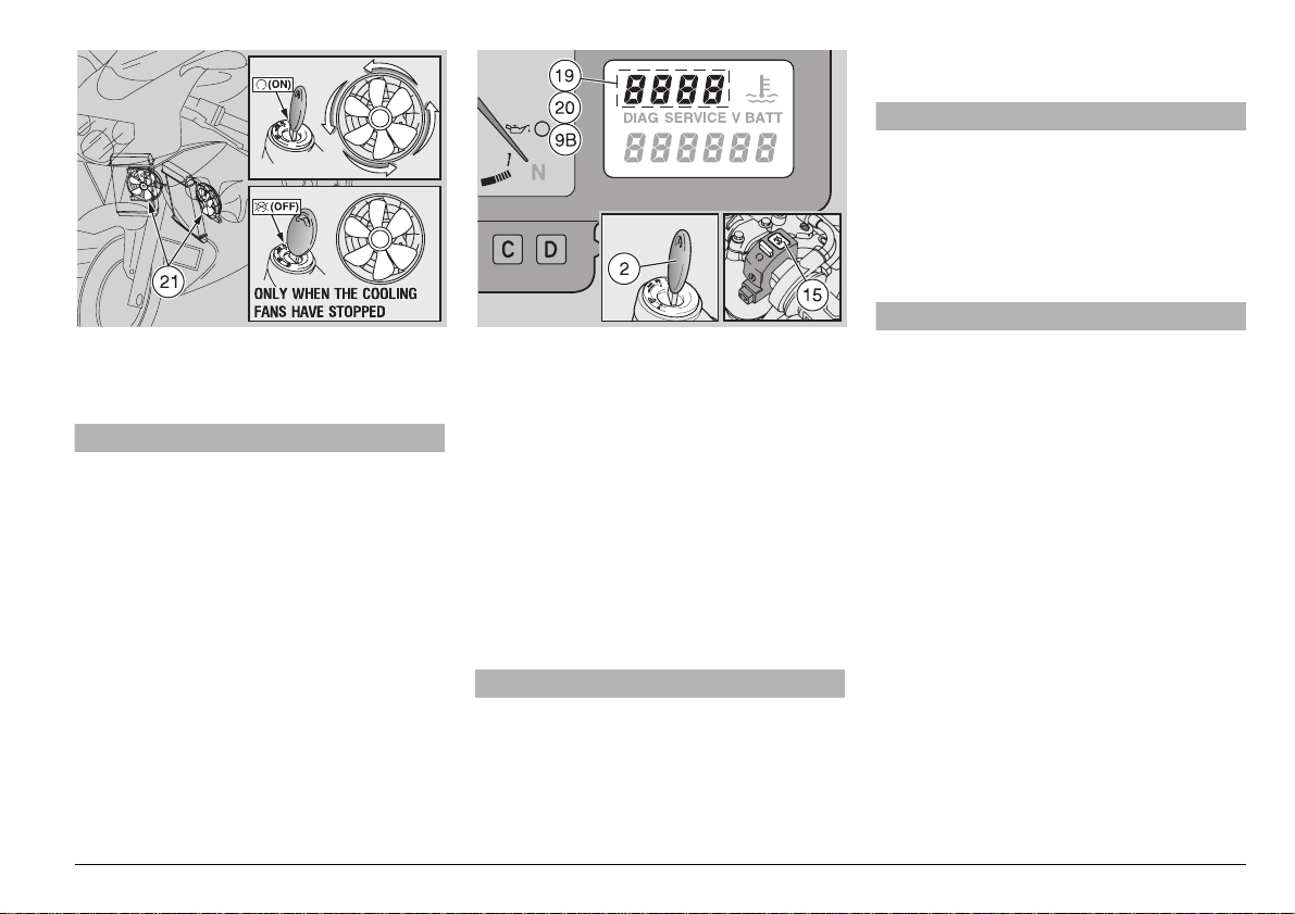
NOTE The coolin g fans (21) funct ion only
when the ignition key (2) is in the “
position.
+” (ON)
aCAUTION
Do not leave the ignition key in the “-”
(OFF) position since the cooling fans
will not run regardless of the coolant
temperature. T his will cause the c oolant temperature to continue to rise.
If, before shutting off the engine, you hear
the cooli ng fans fun ctioning, stop the e n-
gine but leave the ignition key to “
position. This will allow the cooling fans to
draw air through the radiators, and lower
the temperature. Turn the ignition key to
-” (OFF) position only when the cooling
“
fans have stopped.
If, while riding, the right side of the multi-
function display shows a temperature of 115
– 120 °C (239 – 248 °F) (19), stop riding the
vehicle, stop the engine, turn the ignition
+” (ON) position and wait until the
key to “
+” (ON)
cooling fans have sto pped, then turn the ig nition key to “
the coolant level, see p. 56 (COOLANT).
If the symbol “///” (20) is displayed , stop
riding the vehicle and let the engine run at
3,000 rpm for approximately two minutes,
thus allowing the coolant to circulate normally in the cooling system. Then move the engine stop switch to position “
check the coolant level, see p. 5 6 (C OO LANT).
If the symbol “
after the coolant l evel has been che cked,
contact your Local aprilia Dealer.
-” (OFF) positio n and check
m” (OFF) and
///” (20) is still displayed
aWARNING
Do not operate the vehicle if the maxi-
mum temperature [120 °C (248 °F)] is exceeded. Serious engine damage or even
seizure may result which can cause an
upset and serious injury or even death.
Whenever the ignition key (2) is turned to
+” (ON), the right sid e o f th e m ult ifu nction
“
display wi ll show “HIL” (9B) for about
three seconds.
aCAUTION
If the symb ol “HIL” (9B) is displayed
during the normal running of the engine, this means that the electronic unit
has detected an anomaly. In many cases, the engine keeps running with reduced performance levels; immediately
contact your Local APRILIADealer
.
aWARNING
Avoid opening and clo sing the throttle
repeatedly and continuously. Failure to
head this warning can cause you to accidentally lose control of your vehicle.
When you have to brake, close the
throttle and apply both brakes simultaneously in order to obtain the best
brake performance.
By applying only the front brake or only
the rear brake, you re duce the braking
performance considerably and run the
risk of locking up one wheel which can
cause an upset and subsequent serious
injury or even death.
If you stop on an up hill, us e brakes only
to slow the vehicle and to keep it in
place. Slipping the clutch to keep the
vehicle in one place on an uphill grade
will very quickly ruin the clutch and
overheat the engine.
Before enteri ng a turn, slow down, using the brakes and the engine, to a constant speed and then accelerate slightly
use and maintenance RSV mille
-
67
Page 2

through the turn. Av oid braking at the
last moment. Thi s can cause you to
lose control of your vehicle.
If the brakes are operated continuously
on downhill grades, the discs and pads
will overheat, reducing the braking efficiency. Use engine compre ssion and
downshift to retard your vehicle while
going downhill. Use the brakes as little
as possible to maintain a safe speed.
Never coast downhill with the e ngine off
and/or the clutch disengag ed or the
transmission in neutral.
On roads that are wet or covered with
snow, ice or mud, ride very slowly,
avoiding braking or accelerating or maneuvering quickly. Hold the handlebars
firmly.
Failure to heed these warnings can
cause an upset with su bsequent serious injury or death.
Pay very close attention to any obstacles or variations of the road surface.
Uneven roads, rails, manhole covers,
painted traffic stripes, traffic dots all be come slippery when wet. Avoid partic ularly steel pl ates which are som etimes
used during r oad maintenanc e. They
become more slippery than ice once
they are wet by rain. If you must ride on
such surfaces, decrease your speed
and operate the throttle, brakes and
steering very gently.
Always use the turn signals any time
you intend to change lanes or change
direction, and avoid sudden or abrupt
turning.
use and maintenance RSV mille
68
-
Switch off the direction indicators as
soon as you have changed direction.
Overtake and pass only with care, especially in rainy weather when a water
cloud created by larger vehicles reduces
visibility and the slip stream could cause
you to lose control of your vehicle.
25..).').
The internal parts of the engine and transmission must be properly run-in to ensure
their long life and dependable operation.
If possible, while breaking in your vehicle,
ride on hilly roads a nd/ or roa ds w it h many
curves so that the engine and transmission undergo lots of speed changes. It i s
also important that, during the r un-in period, the suspension and brak es be treated
gently to allow the mating parts to bed.
Therefore, avoid hard braking, high
speeds or very bumpy roads during the
break in period.
NOTE Only after the first 937 mi (1500
km) of running-in you can expect the best
performance from the vehicle.
During break in, obey the following rules:
◆
Do not open the throttle abruptly or fully
at low engine speed. This rule applies
even after break in has been completed.
◆
During the first 62 mi (100 km), apply the
brakes with caution, avoid sudden and
prolonged braking. This ensures correct
bedding in of the pads on the discs.
◆
During the first 625 mi (1,000 km), never
exceed 6,000 rpm.
aWARNING
After the vehicle has been operated for
625 mi (1,000 km) perform the “checking
operations” shown in column “After running-in” of the REGULAR SERVICE INTERVALS CHART, see p. 74. Rectify any
faults found. Failur e to heed this warning could lead to damage to your vehicle
or engine s eizure or o ther malfun ction
which could cause an upset and lead to
serious injury or even death.
◆
Between the first 625 mi (1,000 km) and
937 mi (1,500 km) drive more briskly,
changing speed and using maximum acceleration for only a few seconds. Never
exceed 7,500 rpm.
◆
After the first 937 mi (1,500 km) if you
have followed the above break in schedule, the engine should be fully broken in,
and will deliver maxi mum performance.
However, never exceed the ma ximum allowed rpm (10,500 rpm).
Engine maximum rpm
for the running-in
Mileage mi (km) Max. rpm
0 – 625 (0 – 1,000) 6,000
625 – 937
(1,000 – 1,500)
over 937 (1,500) 10,500
7,500
Page 3
34/00).'
aWARNING
If possible, avoid stopping abruptly,
slowing down suddenly and braking at
the last moment.
Failure to comply wi th these instructions may cause an accident with consequent risk of serious injuries or even
death.
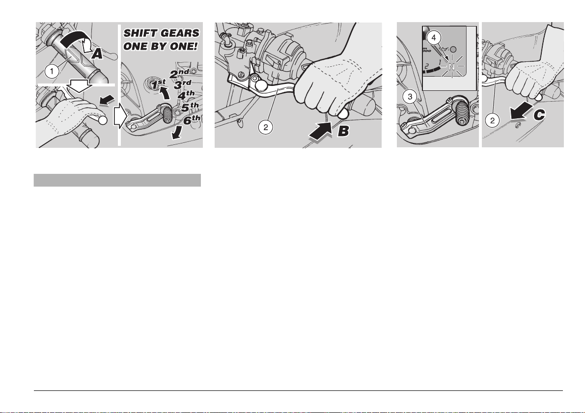
◆
Release the throttle grip (1) (Pos. A),
gradually put on the brakes and at the
same time shift down in or der to decrease the speed, see p. 64 (RIDING).
Once the speed has decrea sed, before
stopping the vehicle:
◆
Pull in the clutch lever (2) (Pos. B) in or-
der to prevent the engine dying.
When the vehicle has come to rest:
◆
Position the shift lever (3) in neutral
(green warning light “
◆
Release the clutch lever (2) (Pos. C).
◆
If you are stopping just briefly and not
q” (4) on).
shutting down the engine, keep one
brake applied.
use and maintenance RSV mille
-
69
Page 4
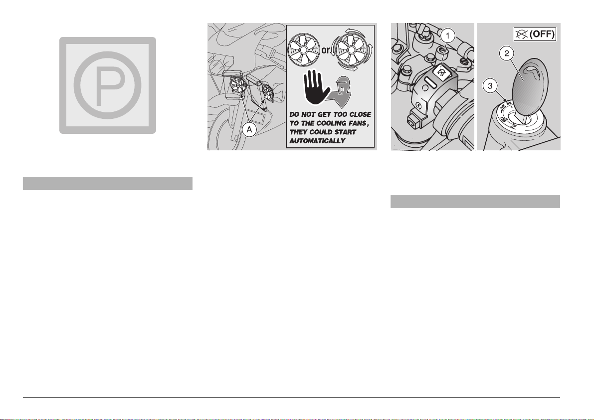
0!2+).'
aWARNING
Park the vehicle only on firm flat
ground, otherwise it could fall over.
Do not lean the vehicle agains t walls, d o
not lay it on the ground.
Park your vehicle away from children
and pedestrians, so that they will not
come in contact with hot parts.
Do not leave you r vehicle unat tended
with the engine running or with the key
in the ignition switch.
Do not sit o n the ve hicle wh en the s ide
stand is down.
Do not get too close to the cooling fans
(A). Even though they are not moving,
they could start automatically and suck
clothing, hair, etc. into the fan.
If the vehicle falls over, it will leak gasoline which is extremely flammable.
Flames or sparks could cause a fire
which could destroy not only your vehicle but also buildings arou nd it and
cause injury or even death to people as
well.
◆
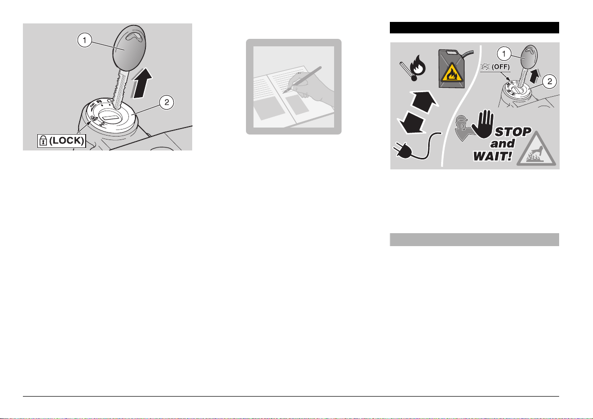
Stop the vehicle, see p . 69 (STOPPIN G).
◆
Move the engine stop switch (1) to the
m” (OFF) position.
“
aCAUTION
Do not leave the ignition on if you have
stopped the engine by moving the engine stop switch to the “
tion as this will discharge the battery.
When the vehicle has come to rest after
stopping the engine with the engine
stop switch, turn the ignition switch (3)
to the “
m” (OFF) position.
◆
Rotate the key (2) and move the ignition
switch (3) to the “
◆
Position your vehicle on the stand, see
p. 71 (POSITIONING THE VEHICLE ON
THE STAND).
m” (OFF) posi-
m” (OFF) position.
use and maintenance RSV mille
70
-
Page 5
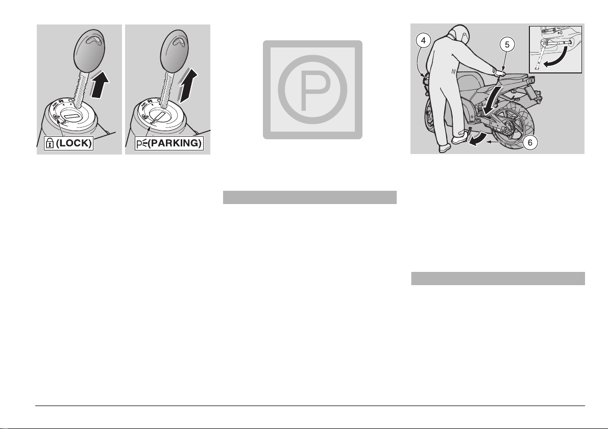
NOTE Neve r leave th e key in the igniti on
switch.
◆
Lock the steering, see p. 40 (STEERING
LOCK) and extract the key.
When you have to park your vehicle in a
dark or badly lighted area (parking lot or
street), it is sometimes useful to leave the
parking lights on s o that you r vehicle will be
easily visible.
To leave the parking lights on: see p. 40
(PARKING LIGHTS).
0/3)4)/.).'4(%6%()#,%
/.4(%34!.$
aWARNING
Position the vehicle on firm and flat
ground.
SIDE STAND
◆
Grab the left handle gri p (4) a nd th e pa ssenger grab strap (5).
◆
Put the side stand (6) down with your
right foot. Make sure it i s exte nded completely and all the way forward.
◆
Lean the vehicle to th e left u ntil the stand
rests firmly on the ground.
◆
Turn the handlebars completely against
the left stop.
aWARNING
Make sure the vehicle is stable when
parked. If it falls down, it will certainly
be damaged and could injure others as
well.
use and maintenance RSV mille
-
71
Page 6
-!).4%.!.#%
35''%34)/.3
4/02%6%.44(%&4
NEVER leave the key (1) in the ignition
switch (2), always use the steering lock “
(LOCK).
Try to park your ve hicle in a safe place, if
at all possible, in a garage or other pro tected place.
Lock your vehicle up using a chain and
padlock around the rear wheel. Chain t he
rear wheel to the swinging arm.
Make sure that all le gal req uire ments : reg istration, license plates, insurance, etc. are
in order.
use and maintenance RSV mille
72
-
Write down your name, address and telephone number and the vehicle identification number in the space below, to facilitate finding the owner in case your vehicle
s”
is recovered after theft.
SURNAME: ...............................................
NAME: ......................................................
ADDRESS: ...............................................
...................................................................
TELEPHONE NO.: ...................................
NOTE Ver y often stolen vehicles are
identified thanks to the data written in the
use/maintenance manual.
Carefully read p. 2 (FOREWORD) and
(INTRODUCTION), p. 3 (SAFETY WARNINGS) and (GENERAL SAFETY RULES),
p. 5 (WARN INGS - PRECAUTIONS GENERAL ADVICE).
aWARNING
Risk of fire.
Keep fuel and other flammable sub-
stances away from the electrical components.
Before beginning any main tenance operation or any inspection of the vehicle,
stop the engine, remove the key (1)
from the ignition swi tch (2), wait until
the engine and the e xhaust syst em have
cooled down and if possible lift the vehicle by means of the pro per equipment, on firm and flat ground.
Before proceeding, make sure that the
room in which you are working is properly ventilated.
Page 7
Be careful to avoid hot parts of the engine and exhaust system. They are hot
enough to cause serious burns.
Avoid the temptation to hold any part of
the vehicle in your mouth . The c oati ngs
and platings used are, in some cases,
toxic.
aCAUTION
In general, reas sembly is perfor med in
the reverse order of the disassembly instructions given here.
For some maintenance operations, especially those in which your hands are
likely to come in contact with coolant,
or engine oil, or gasoline, or bra ke fl uid,
it is advisable to use thin disposable
gloves, such as thos e made of latex,
rubber or nitrile.
The routine maintenance operations described in this manual can usually be performed by the user. However, in some
cases, specific tools a nd technical expertise may be required.
Do not hesitate to contact your Local aprilia
Dealer who has all the latest factory information and tools to properly service your
vehicle.
Remember that many s ervic e opera tions, if
done improperly, can be very hazardous.
If you have any quest ions abou t your abili ty
to carry out the operations described here,
contact yo ur Local aprilia Dealer.
In all cases, personally carry out the “pre-
liminary checking operations” after any
maintenance, see p.61 (PRELIMINARY
CHECKING OPERATIONS).
aWARNING
Remember that tightening torq ue of all
fasteners on the wheels, brakes, axles,
suspension are extremel y important to
ensure safety, and must be maintained
at the prescribed values.
Check the tightening torques of the fasteners regularly, and always use a
torque wrench when installing them.
Failure to adhere to this warning could
cause the loosening and subsequent
loss of critical f asteners, which could
cause a wheel to lock or cause other
handling prob lems with consequent
overturning, and the risk of serious injury or even death.
aWARNING
Fasteners mu st be neither over tightened or undertightened. If they are
overtightened, the threads ma y be dam aged and the fa steners will be destroyed, whereas if they are undertightened, they can vibrate and become lost.
Obviously, under these circumstances,
a serious accident with resultant serious injury or death could ensue.
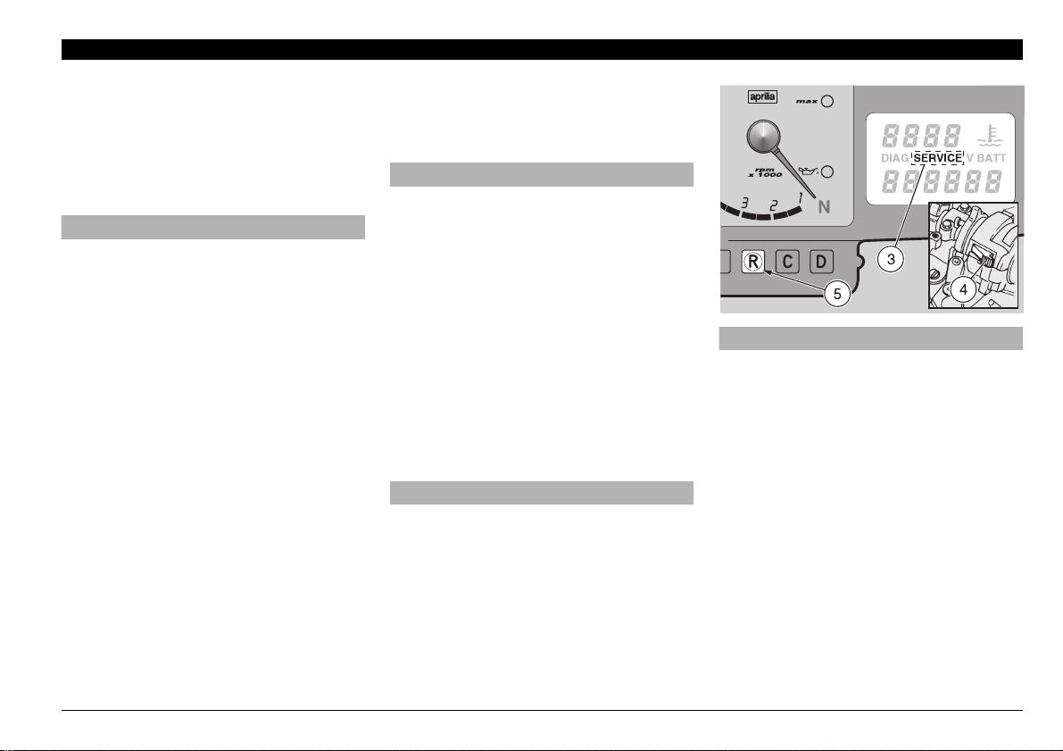
aCAUTION
After the first 6 25 mi (1,000 km) and successively every 4,687 mi (7,500 km), the
word “SERVICE” (3) appear s on the ri ght
display. In this case contact your Local
APRILIADealer, who will carry out the operations indicated in the regular service
intervals chart, see p. 74 (REGULAR SERVICE INTERVAL S CHA RT).
To make the word “SERVICE” disappear,
press the “LAP” push button (4) and then
the push butto n
pressed for about 5 seconds.
(5) and ke ep them
R
use and maintenance RSV mille
-
73
Page 8

2%'5,!23%26)#%).4%26!,3#(!24
THESE OPERATIONS MAY BE CARRIED OUT BY YOUR Local APRILIADealer, OR BY THE OWNER OF THE VEHICLE
Component
Tightness of the battery termin al s C C
Spark plugs C (*) S
Drive chain, tension and lubrication every 625 mi (1,000 km): C
Air cleaner CS
Fork C
Light operation/direction C
Light system C C
Safety switches C C
Clutch fluid C
Brake fluid C
Coolant every 625 mi (1,000 km): C
Engine oil every 312 mi (500 km): C
Tires C every 625 mi (1,000 km): C
Tire pressure R every month: R
Engine idling rpm R R
Engine oil pressure warning light LED “
Front and rear brake pad wear before every trip and every 4,687 mi (7,500 km): C
C = check and clean, adjust, lubricate or change, if necessary; P = clean; S = change; R = adjust.
Perform these maintenance opera tions at on e-ha lf of he s pec ified interv als , if you r v ehi cle is often used in rainy or very dusty
conditions, on unpaved roads, or in any kind of competition.
\”
After running-in
[625 mi (1,000 km)]
Every 4,687 mi
(7,500 km) or 8 months
at every start: C
Every 9,375 mi
(15,000 km) or 16 months
(*) = For competition use, change every 2,343 mi (3,750 km).
use and maintenance RSV mille
74
-
Page 9

THESE MAINTENANCE OPERATIONS SHOULD ONLY BE PERFORMED OUT BY Local APRILIADealer.
Component
Accelerator cables (adjustmen t) C
Rear suspension linkage bearings C
Steering bearings and steering C C
Wheel bearings C
Engine oil filter S S (*)
Engine oil filter (on oil tank) P P
Engine oil S S (*)
Tappet clearance R R
Braking systems C C
Cooling system C
Clutch fluid C every 2 years: S
Brake fluid C every 2 years: S
Brake pads if worn: S
Coolant every 2 years: S
Fork oil After the frist 4,687 mi (7,500 km): S / every 14,000 mi (22,500 km): S
Wheels/tires C
Nut, bolt, screw tightening C C
Suspensio ns and attitude C C
Brake fluid bleeding C
Fuel pipes C every 4 years: S
C = check and clean, adjust, lubricate or change, if necessary; P = clean; S = change; R = adjust.
Perform these maintenance operations at one-half of he sp ecifi ed in terva ls, if y our ve hicl e is o ften us ed in rainy or very dusty
conditions, on unpaved roads, or in any kind of competition.
After running-in
[625 mi (1,000 km)]
Every 4,687 mi
(7,500 km) or 8 months
Every 9,375 mi
(15,000 km) or 16 months
(*) = For competition use, change every 2,343 mi (3,750 km).
use and maintenance RSV mille
-
75
Page 10
)$%.4)&)#!4)/.$!4!
It is a good idea to write down the frame
and engine numbers in th e space provided below. Use the frame number (VIN) to
identify your vehicle when ordering sp are
parts.
aWARNING
In all states and countries, it is against
the law to alter the Vehicle Identification
Number (VIN). You ca n incur severe
penalties by doing this. Also, this will
immediately invalidate your warranty.
FRAME NUMBER
The frame number is stamped on the right
side of the fork head.
Frame no.
ENGINE NUMBER
The engine number is stamped on the rear
part of the left engine crankcase.
Engine no.
!)2#,%!.%2
Carefully read p. 72 (MAINTENANCE).
aWARNING
Do not use gasoline or flammable solvents to wash the air cleaner, in order to
avoid fire or explosion.
Inspect the air cleaner to ensure that it has
not become clogged every 4,68 7 mi (7,50 0
km) or 8 months of use. Renew the air
cleaner every 9,375 mi (15,000 km).
The air cle aner must be inspected mo re
frequently, cleaned if necessary, and replaced more fre quently if the vehi cle is
used on dusty or wet roads.
More frequent cleaning of the air cleaner is
suggested, especially if yo ur bike is used
under very dusty conditions.
use and maintenance RSV mille
76
-
Page 11
pressed air jets, they can cause serious
personal injur y if directed towards your
body.
◆
Grasp the air cleaner vertic ally and stri ke
it repeatedly on a clean har d horizontal
surface.
◆
If available, clean the air cleaner with a
compressed air jet, directi ng it from the
inside of the filter towards the outside.
◆
Clean the outer part of the air cleaner
with a cloth.
aCAUTION
The air cleaner must not be use d for
more than 9,375 mi (15,000 km) regardless of how many times it has been
cleaned in the interval. Under very
dusty or dirty conditions, it is advisable
to replace the air filter more often.
Before the cleaning operation, it is necessary to remove the air cleaner from the vehicle.
REMOVAL
◆
Lift the fuel tank, see p. 94 (LIFTING
THE FUEL TANK).
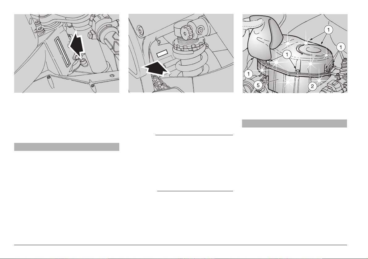
aCAUTION
Before unscrewing and removing the
screws (1), clean the filter cas e cover (2)
and the filter case (5) with a clean cloth.
Prevent any foreign matter from getting
into the inlet tubes. This could cause
severe engine damage.
◆
Unscrew and remove the seven screws
(1) that fasten the filter case cover (2).
◆
Remove the filte r case cover (2).
◆
Extract the air cleaner (3).
aCAU TION
Plug the opening with a clean cloth to
prevent any foreign matter from entering the intake tubes.
CLEANING
aCAUTION
Take great care not to deform the perforated metal outside screen. It is very
fragile and can be easily damaged. Never use a screwdriver or other sharp hard
tool to remove the air cleaner itself.
aWARNING
During this operation, always wear goggles which provide your eyes with 360°
protection. Be very careful using com-
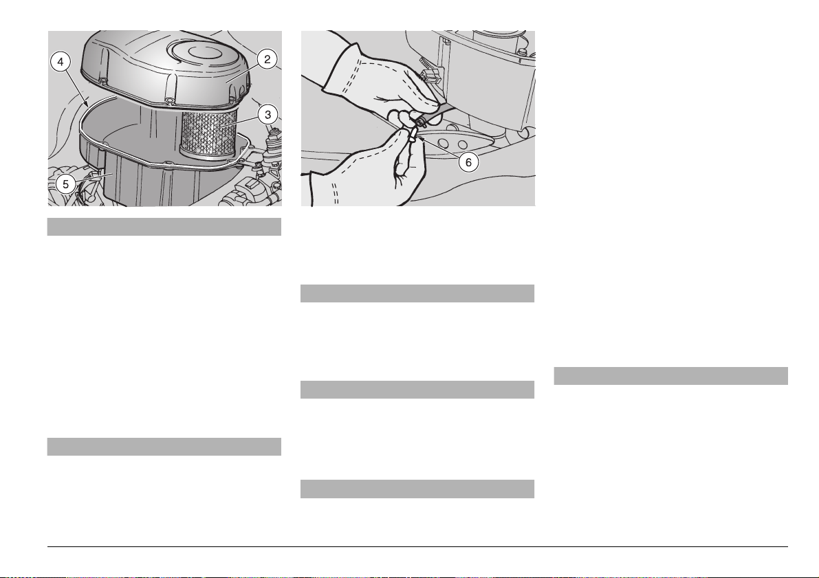
CHANGING
◆
Replace the air cleaner with a new one
of the same type.
◆
Make sure that the gasket (4) of the filter
case (5) is intact; if it is damaged, replace it.
◆
Every 4,687 mi (7,500 km) remove the
plug (6) so that any dirt that may have
accumulated inside the filter case can be
removed.
aCAUTION
When cleaning the air cleaner, make
sure that there are no tears. Otherwise,
replace the air cleaner.
Make sure that the air cleaner is positioned correctly, in such a way as to prevent non-filtered air from entering.
Premature wear of the piston ring s, pistons and cylinders is caused by an improperly installed air cleaner.
use and maintenance RSV mille
-
77
Page 12
#(%#+).'4(%%.').%/),,%6%,
!.$4/00).'50
Carefully read p. 46 (LUBRICANTS),
p. 72 (M AINTENANCE) and p. 122 (LU BRICANT CHART) .
aWARNING
It is critical to the safe operation of your
vehicle that the proper lubricants, mai ntained at the proper levels, are used.
Failure to heed this warning can lead to
an engine seizure wit h subseq uent accident, serious injury or death.
aWARNING
Remember that the tightening torque of
all fasteners on the wheels, brakes, axles, and other components of the suspension system is very important to ensure the safety of the vehicle, and must
be kept at the prescribed values.
Check the tightening torque of the fasteners regularly, and always use a
torque wrench when reinstalling them.
Failure to comply with this warning
could allow one of these compon ents to
be lost which could lock a wheel or
cause other handling pro blems with
consequent overturning and risk of serious injury or even death.
CHECKING
NOTE Positi on the vehicle on firm a nd
flat ground.
aCAUTION
The engine oil level must be checked
with warm engine.
If the check is carried out with cold engine, the oil level may temporarily lower
below the “MIN” mark.
This is not a problem, provided that the
engine oil pressure warning light LED
j” does not come on, see p. 30 (IN-
“
STRUMENTS AND INDICATORS TABLE).
aWAR NING
Exhaust gases co ntain carbon monoxide, which is extremely poisonous if inhaled.
Do not start the engine in closed or badly-ventilated rooms.
Failure to observe this warning may
cause loss of consciousness or even
lead to death by asphyxia.
◆
Check the oil when the engine is warm,
having been ridden for at least 10 mi (16
km).
NOTE If the engine is cold, warm it up
for riding, preferably on a hilly road, for approximately 10 mi (16 km) before checking
the oil.
◆
Stop the engine before checking the oil.
aWARNING
Should your vehicle overturn, it will leak
gasoline, which is extrem ely flamm able.
Flames or sparks may cause a fire,
which could destroy not on ly the vehicle, but also the bu ilding in which it is
located, and cause serious injuries or
even death.
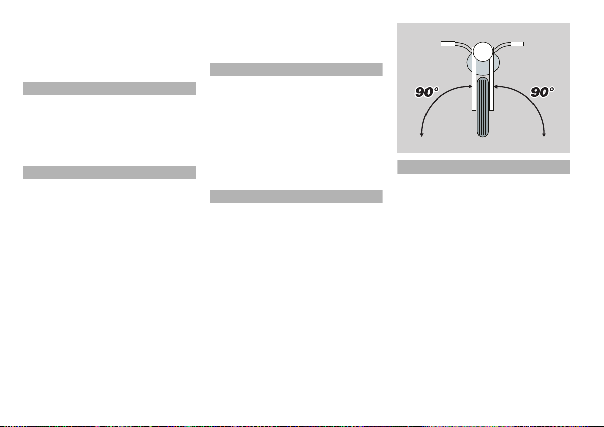
◆
Keep the vehicle in vertical position, with
the two wheels resting on the ground.
NOTE If yo u attemp t to chec k the oil with
the vehicle leaned in either direction from
the vertical, your measurement w ill be inaccurate.
NOTE If the engine oil tank is dirty, wipe
it with a clean c loth s o th at y ou can see the
“MIN” and “MAX” marks.
◆
Look through the appropriate slot (1) in
the left fairing. Check the level of the oil
in the sight gauge (2).
use and maintenance RSV mille
78
-
Page 13
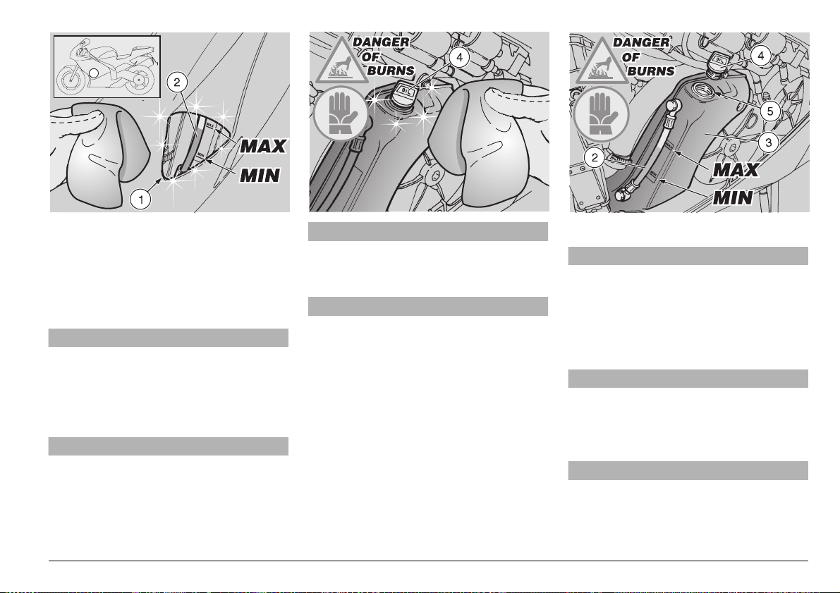
MAX = maximum level
MIN = minimum level
The difference between “MAX” and
“MIN” is about 0.53 US qt (500 cm#).
◆
The level is correct if the oil reaches approx the “MAX” mark.
aWARNING
Never exceed the “MAX” mark, nor
leave the oil below the “MIN” mark, in
order to avoid serious damage to the
engine.
If necessary, top up the engine oil tank:
aWARNING
When warmed up, the engine contains
hot oil and the engine oil tank (3) is
warm; therefore, while carrying out the
operations describe d here below be
particularly careful, in order to avoid
burns.
aCAU TION
Use thick gloves to prevent burns.
◆
Remove the left fairing, see p. 96 (REMOVING THE SIDE FAIRINGS).
aCAU TION
Before unscrewing and removing the
filler cap (4), clean it and the area of the
tank around it with a clean cloth. Prevent any foreign matter from falling into
the oil tank, this could cause serious
engine damage.
Do not use any flammable solvents
such as alcohol or gasoline when wip ing the oil tank. The oil tank is hot
enough to cause igniti on of flammable
solvents.
Use only a nature fiber cloth, i.e. cotton .
Man made fabrics such as polyester,
etc. could ignite.
◆
Unscrew and remove the filler cap (4).
aCAUTION
When topping up, never exceed the
“MAX” level.
◆
Top up the engine oil tank (3) through the
filler neck (5), with high-quality engine oil,
see p. 122 (LUBRICANT CHART).
◆
Replace and tighten the filler cap (4).
aWARNING
Tighten the filler cap (4) snugly to insure no oil leak.
◆
Replace the left fairing, see p. 96 (REMOVING THE SIDE FAIRINGS).
aWARNING
Never ride your vehicle with low engine
oil, or with contaminated oil, or with unapproved oil. Any of these will greatly
accelerate wear of yo ur engine, and
cause irreparable damage.
use and maintenance RSV mille
-
79
Page 14
#(%#+).'4(%3)$%34!.$
Carefully read p. 72 (MAINTENANCE)
and p. 81 (CHECKING THE SWITCHES).
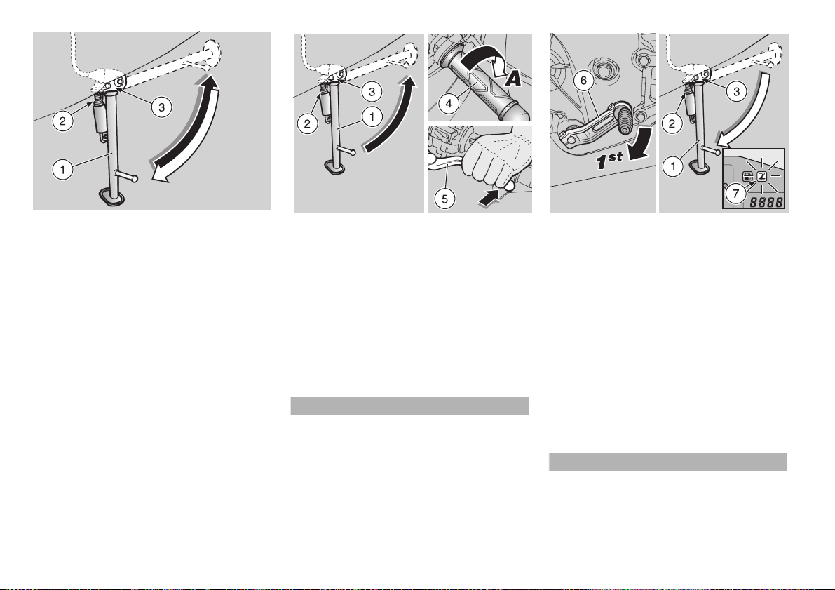
The side stand (1) must rotate about its
pivot smoothly and easily.
Perform the following checks:
◆
The springs (2) must be free from damage, wear, or rust, and must fully and
firmly retract the side st and when the
weight of the vehicle is lifted off of it.
◆
The side stand (1) must rotate freely
about its pivot. If necessary, lubricate
the pivot, see p. 122 (LUBRICANT
CHART).
#(%#+).'4(%&5.#4)/.).'
/&4(%3!&%4937)4#(
/.4(%3)$%34!.$
The side stand (1) is equipped with a safety system, operated by safety switch (3).
use and maintenance RSV mille
80
-
This system prevents the motor from being
started while the stand is extended unless
the transmission is in neutral. It also kills
the engine if the stand is extended while
the engine is running, unless the transmission is in neutral.
T o check the proper funct ioning of th e safety switch (3):
◆
Sit on the vehicle in the normal ridi ng position.
◆
Retract the side stand (1).
aWAR NING
Exhaust gases co ntain carbon monoxide, which is extremely poisonous if inhaled.
Do not start the engine in closed or badly-ventilated rooms.
Failure to observe this warning may
cause loss of consciousness or even
lead to death by asphyxia.
◆
Start the engine, see p. 62 (STARTING).
◆
Release the throttle grip (4) (Pos. A).
With the engine idling, pull in the clutch
lever (5) completely.
◆
Engage first gear, pushing the shift lever
(6) downwards.
◆
Extend the side stand (1).
NOTE Extending the side stand mu st kil l
the engine and the “side stand down” warning light “
gine continues to run:
◆
◆
\” (7) must come on. If the en-
Check the s afety switch (3) o n the side
stand (2), see p. 81 (CHECKING THE
SWITCHES). Perform t he necessary
cleaning or repairs.
Repeat the check.
aWARNING
If the engine does not stop when the
side stand is extended, do not ride your
vehicle. Contact your Local APRILIA
Dealer.
Page 15
#(%#+).'4(%37)4#(%3
Carefully read p. 72 (MAINTENANCE).
Check the switches after the first 625 mi
(1,000 km) and thereafter every 4,687 mi
(7,500 km).
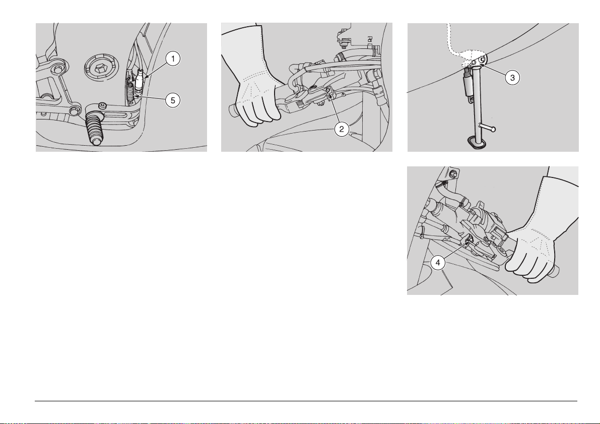
The vehicle is equipped with four switches:
– stoplight switch on the rear brake pedal
(1);
– stoplight switch on the front brake lever
(2);
– safety switch on the side stand (3);
– clutch lever switch (4).
◆
Make sure that there is no dirt or mud on
the switch. The switch pin must move
freely and without interference, returning
automatically to its unapplied position.
◆
Check the spring (5) ; it must not be dam aged, worn or stretched.
use and maintenance RSV mille
-
81
Page 16
).30%#4).'4(%&2/.4
!.$2%!23530%.3)/.3
aCAU TION
The front fork oil change operation
should be entrusted to your L ocal APRIL
IADealer.
Carefully read p. 72 (MAINTENANCE).
Have the front fork oil chan ged after the
4,687 mi (7,500 km) an d thereafter every
14,000 mi (22,500 km).
Every 4,687 mi (7,500 km), carry out the
following checking operations:
◆
Apply the front brake lever and push up
and down on the ha ndlebar repeate dly,
pushing the fork up and down.
The fork must move smoothl y and easily,
there must be no trace of oil on the fork
tubes.
◆
Check the t orque of all th e fasteners on
the front fork and inspect the entire front
fork to make sure that it is in good condition without leaks or dam age. Repeat for
the rear suspension and swinging arm.
aCAUTION
Do not ride your vehicl e if either suspension is damaged in any way, contact
your Local APRILIADealer.
&2/.43530%.3)/.
The front suspension consists of an hydraulic fork connected to the steering column by means of two plates.
For the setting of the vehicle attitude, each
rod of the fork is provided with an upper
screw (1) f or t he ad j us t me nt of t he hy dr a ulic damping on extension, a lower screw (2)
for the adjustment of the hydrauli c damping on compression and an upper nut (3)
for the adjustment of the spring preload.
NOTE It is possible to adj us t the atti tud e
of the vehicle, by changing the height of its
front part.
For this type of adjustment, contact your
Local aprilia Dealer.
use and maintenance RSV mille
82
-
Page 17

ADJUSTING THE FRONT FORK
The front fork is adjusted at the factory to
suit most riding conditions for most riders.
However, it is pos sible to adjust the fork s etting to your preference, and to accommodate the full range of operating conditions
that the vehicle is intended to be used for.
aCAUTION
When adjusting the fr ont fork, always
start from the most rigid setting. Do not
rotate adjusters (1) and (2) beyond their
limit position, to avoid damaging the
threads.
Use the notches (1) and (2) provided on
the adjusters as refere nce ma rks for the
adjustment of hydraulic damping on extension and hydraulic damping on compression.
Turn the adjusters (1) and (2) 1/8 turn at
a time and turn the a djus ting nut (3) one
notch at a time. Then, test the ve hicle
on the road, to ensure you have obtained the optimal adjustment.
Make sure that the spring preload and
hydraulic damping, both on extension
and compression, is the same for both
sides. A different shock absorber setting on the left and right side will decrease the stability of the vehicle.
When the spring preload is increased, it
is necessary to also increase the hydraulic damping, both on extension and
compression, to avoid a jerky unsteady
shock action while riding.
Upper screw adjusters
(1) (2.25 turns in total)
Function Increase of the hydraulic
Recommended kind
of road
Notes Rider and passenger Solo rider
Standard adjustment From the completely clockwise position, 1.5 turns counter-
Lower screw adjusters
(2) (2 turns in total)
Function Increase of the hydraulic
Recommended kind
of road
Notes Rider and passenger Solo rider
Standard adjustment From the completely clockwise position, 1.5 turns counter-
Upper adjusting
nuts (3)
(8 notches in total)
Function Spring preload increase Spring preload decrease
Attitude The vehicle is more rigid The vehicle is less rigid
Recommended kind
of road
Notes Rider and passenger Solo rider
Standard adjustment Turn the adjustin g nut 5 notch es cou nte rcl oc kwis e from the
By rotating them
clockwise (H)
damping on extension
Smooth or normal roads Roads with uneven surface
clockwise
By rotating them clockw ise
(H)
damping on compression
Smooth or normal roads Roads with uneven surface
clockwise
By rotating them clockwise
(screwing)
Smooth or normal roads Roads with uneven surface
fully clockwise setting
By rotating them
counterclockwise (S)
Decrease of the hydraulic
damping on extension
By rotating them
counterclockwise (S)
Decrease of the hydraulic
damping on compression
By rotating them
counterclockwise
(unscrewing)
use and maintenance RSV mille
-
83
Page 18
2%!23530%.3)/.
The rear suspension consists of a hydraulic shock absorber - spring unit, which is
mounted to the frame with a uniball, and to
the swinging arm by means of a system of
levers.
The ride height of the rear of the vehicle
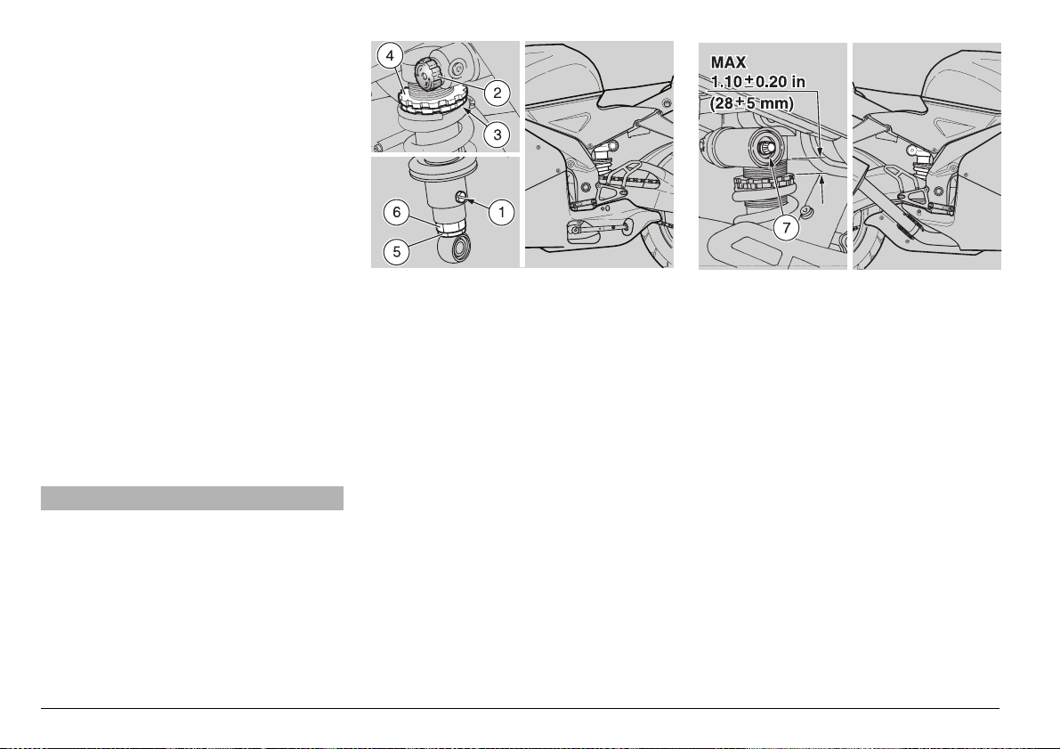
can be set using the spring preload adjusting ring nut (3) and locking ri ng nut, (4).
The rear suspension can be tuned by adjusting the extensi on damping with a spring
adjuster (1), the damping on compression
can be adjusted by a knob (2).
ADJUSTING
THE REAR SHOCK ABSORBER
The rear shock absorber is set at the factory to satisfy most ridin g conditi ons, at either
low or high speed, and with e ithe r a li ght or
full load. However, it is pos sible to tu ne the
suspension to y our prefe rence by u sing the
above mentioned adjustments.
aCAU TION
When adjusting the rear shock absorber,
always start from the stiffest position.
This is the fully clockwise position of the
extension damper adjusti ng screw (1)
and the compression damper knob (2).
Do not rotate the extension damper adjustment screw (1) beyond its limit , this
will damage the screw and destroy your
shock absorber.
Always make sure, when adjusting
screw (1), that it clicks in to an adjustment notch, and is not at a position intermediate between adjustment notches.
The distance between the top of the adjustment ring and the top of the threads
must not exc eed 1.10 ± 0.2 0 in (28 ± 5
mm). Adjusting the nut further down on
the shock will compress the spring excessively, and result in an uneven
bumpy ride. Also, it will be impossible to
adequately adjust the extension damping using screw (1).
◆
Loosen the locking rin g nu t (4) b y m ean s
of the appropriate spanner wrench.
◆
Adjust th e adjus ting ri ng nut (3) (see figure).
◆
If necessary, adjust the extension damping screw (1) (see table p. 85).
◆
Once the ride height has been properly
adjusted, tighten the lock ring nut (4)
completely.
◆
Slightly loosen the lock nut (5).
Rotate the adjuster (6) one tu rn at a time
so that the adjusting screw (1) faces out
to the left side of the vehicle.
◆
Using the appropriate wrench, turn the
adjuster ( 6) (whi ch adjust s the ce nter to
center distance of the shock absorber
unit) (see table p. 85).
use and maintenance RSV mille
84
-
Page 19
NOTE Adjust the spring preload and the
extension damping according to t he vehicle use. When the spring preload is increased, it is also necessary to increase
the extension damping in order to avoid a
bumpy uneven ride.
Especially at hi gher preload setti ngs, it is
advisable to use full extension damping
(screw (1) fully clockwise) or only a couple
of clicks clockwise, to avoid a bumpy uneven ride. If necessa ry, c on tac t y our L oc al
aprilia Dealer.
Never remove the plug (7) o r attempt to adjust the valve covered by it. This may
cause nitrogen to escape which will destroy the function of the shock absorber
and could upset the handling of your vehicle, leading to an ac ciden t with subse quent
injury or even death.
Never exceed 2-3 clicks with the extension
damping adjustment (1) or 5-6 cli cks with
the compression dampi ng a dju stmen t kn ob
(2), or one turn with the preload adjusting
nut (3) at any given ad justment attempt.
Ride the vehicle for more than just a few
miles on the road between each adjustment, to determine the adjustments most
suitable to your use.
Screw adjuster (1)
(27 clicks)
Function Increase of the hydraulic
Recommended kind
of road
Notes Rider and passenger Solo rider
Standard adjustment Turn the screw adjuster 14 clicks counterclockwise from its
Knob adjuster (2)
(40 clicks)
Function Increase of the hydraulic
Recommended kind
of road
Notes Rider and passenger Solo rider
Standard adjustment Turn the knob 10 clicks clockwise f rom its completely open,
Adjusting ring nut (3) By screwing it By unscrewing it
Function Spring preload increase Spring preload decrease
Attitude The vehic le is more rigid The vehicle is less rigid
Recommended kind of
road
Notes Rider and passenger Solo rider
Adjusting nut (6) By unscrewing it By screwing it
Function Increase the cen ter-to-center
Attitude The vehic le is highe r The vehicle is lower
Recommended kind
of road
Notes Rider and passenger Solo rider
By rotating it clockwise (H) By rotating it
damping on extension
Smooth or normal roads Roads with uneven surface
most clockwise position
By rotating it
clockwise ( +)
damping on compression
Smooth or normal roads Roads with uneven surface
most counterclockwise position
Smooth or normal roads Roads with uneven surface
mount distance
Roads with uneven surface Smooth or normal roads
counterclockwise (S)
Decrease of the hydraulic
damping on extension
By rotating it
counterclockwise (–)
Decrease of the hydraulic
damping on compression
Decrease the center-tocenter mount distance
use and maintenance RSV mille
-
85
Page 20

#(%#+).'4(%"2!+%0!$7%!2
Carefully read p. 47 (BRAKES), p. 48
(DISC BRAKES) and p. 72 (MAINTENANCE).
NOTE Your vehicle is equipped with
disc brakes and two separate brake systems.
The front brake system is equipped w ith
two discs, one on the right and one on the
left side of the front wheel.
The rear brake system is equipped with a
single disc on the right side of the wh eel.
The following information may re fer to a
single braking system, but is applicable for
both braking systems.
Check the brake pa d wear after the first
625 mi (1,000 km), before every trip and
thereafter every 4,687 mi (7,500 km).
The amount of wear that the brake pads
experience depends on how the vehicle is
used, how aggressively it is driven, and
the condition of the roads upon which it is
operated. Wear will be faster than no rmal
when the vehicle is driven aggressively, or
on dusty or wet roads.
aWAR NING
Check the wear o f the brake pad s before ever y trip.
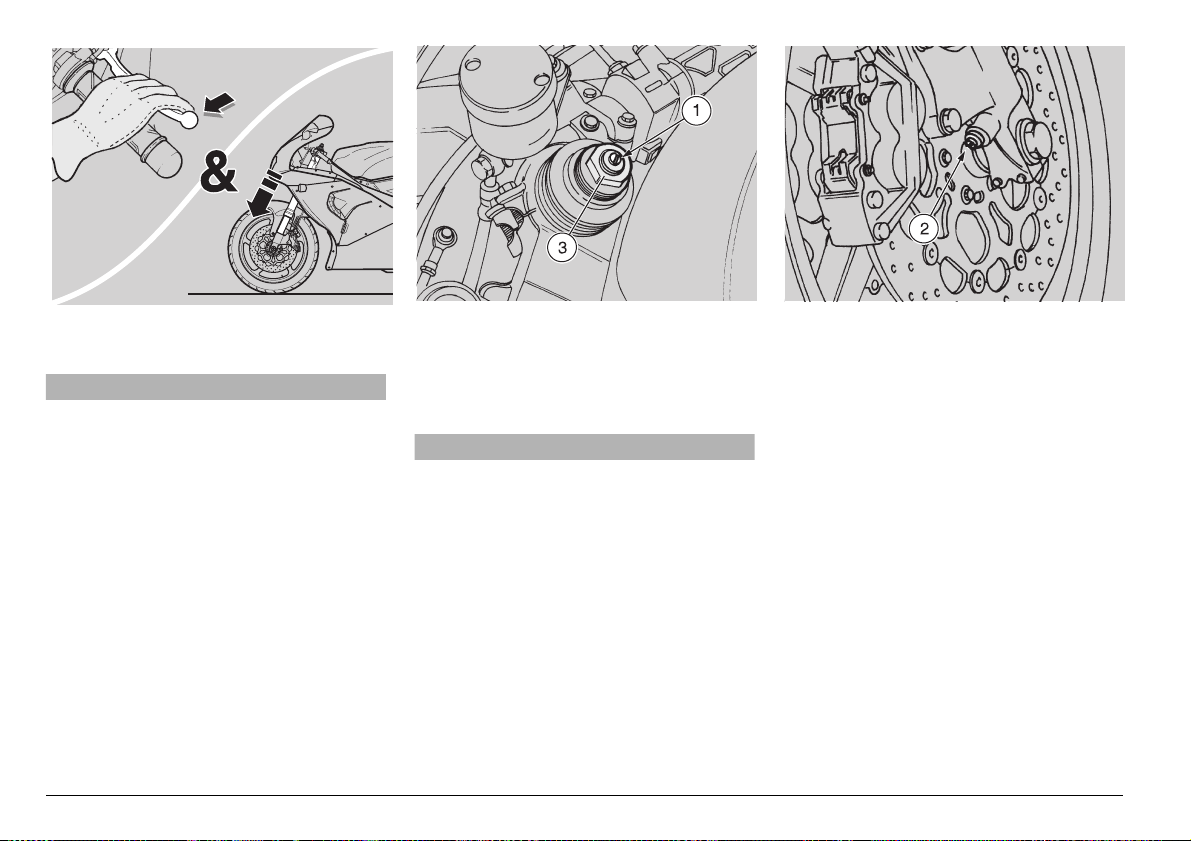
CHECKING WEAR OF T HE BRAKE
PADS
◆
Place the vehicle on the stand, see p. 71
(POSITIONING THE VEHICLE ON THE
STAND).
◆
Perform a visual check of the fric tion material thickness. Use a flashlight. See
the arrows (1) and (2) above.
If the friction material on one pad of a pair,
front (3) or re ar (4) , is w orn to 0.06 in (1.5
mm) or less, replace both pads.
aWARNING
Excessive wear of the friction m aterial
would cause the contact of the pad metal support with th e disc, with consequent metallic noise and production of
sparks from the caliper; braki ng efficiency and safety will be s eriou sly com promised. This could lead to a crash,
with subsequent serious injury or
death.
aWARNING
Have the pads changed by your Local
APRILIADealer.
use and maintenance RSV mille
86
-
Page 21

#(%#+).'4(%34%%2).'
The operations necessary to this check
require specific skills and therefore
should be carried out by your Local
APRILIADealer.
#(%#+).'
4(%37).').'!2-0)6/4
The operations necessary to this check
require specific skills and therefore
should be carried out by your Local
APRILIADealer.
0/3)4)/.).'4(%6%()#,%/.
4(%2%!23500/2434!.$&
NOTE Have so meon e help you kee p the
vehicle in vertical position with the two
wheels on the ground.
aWARNING
Lift the vehicle by grasping the two pins
(1) only.
◆
Lift (Pos. A) the rear part of the stand
(2), insert it from the back of the vehicle
and position it so that the two housings
(3) of the support pins (4) hook the two
pins (1) provided on the vehicle.
If the housings (3) do not a lign with the two
pins (1):
◆
Loosen the two knob (5).
◆
Slide the two support pins (4) so that the
two housings (3) of the support pins (4)
coincide with the two pins (1).
◆
Tighten the two knobs (5).
◆
Lift (Pos. A) the rear part of the stand
(2), insert it from the back of the vehicle
and position it so that the two housings
(3) of the support pins (4) hook the two
pins (1) provided on the vehicle.
◆
Rest one foot on the rear part of the
stand (2).
◆
Push (Pos. B) the stand (2) downwards
until it reaches the end of its stroke (see
figure).
0/3)4)/.).'4(%6%()#,%/.
4(%&2/.43500/2434!.$
◆
Position the vehicle on the appropriate
rear support stand
SITIONING THE VEHICLE ON THE
REAR SUPPORT STAND
◆
Lift (Pos. C) the front part o f the stand (6)
and insert the its two ends of the stand
(7) in the two holes (8) positioned on the
lower ends of the front fork.
◆
Rest one foot on the front part of the
stand (6).
◆
Push (Pos. D) the stand (6) downwards
until it reaches the end of its stroke (see
figure).
use and maintenance RSV mille
&, see beside (PO-
&).
&
-
87
Page 22

&2/.47(%%,
aWARNING
The disassembly and reassembly of the
front wheel can be diffic ult for t hose u nfamiliar with vehicle maintenance. You
may wish to have your Local APRILIA
Dealer car ry out thes e operatio ns.
If you wish to perform these operations
yourself, caref ully read p. 72 (MAINTENANCE).
While disassembling and reassembling
the wheel, pay extra care not to damage
the brake lines, discs or pads.
Before carrying out the following ope rations, let the engine and the exhaust silencer cool down until they reach room
temperature, in order to avoid burns.
NOTE You must use the ap propriate
front and rear support stands to remove
the front wheel.
use and maintenance RSV mille
88
-
DISASSEMBLY
◆
Position the vehicle on the appropriate
rear support stand
(POSITIONING THE VEHICLE ON THE
REAR SUPPORT STAND
◆
Position the vehicle on the appropriate
front support stand & (2), see p. 87
(POSITIONING THE VEHICLE ON THE
FRONT SUPPORT STAND
& (1), see p. 87
&).
&).
aWAR NING
Make sure that the vehicle is stable.
If it falls over, it ma y cause damage to
bystanders and other p roperty, as well
as being damaged itself.
◆
Have a helper steady the handlebar in
the straight ahead position.
◆
Remove the left and right front bra ke caliper (3), see p. 98 (REMOVING THE
FRONT BRAKE CALIPERS).
aCAU TION
Never touch the front brake lever after
removing the brake calipers from the
discs. If you do, the cali per pistons ma y
be pushed out of their seats, and brake
fluid will be spilled. Shou ld you accidentally do this, take you r vehicle to
your Local APRILIADealer who will know
how to repair this damage.
◆
Place a support (4) under the front tire, in
such a way as to keep the wheel in its
position after loosening it.
◆
Hold the axle (5) from rotating with an
appropriate Allen wrench .
Wheel nut (6) tightening torque:
57.86 ftlb (80 Nm).
◆
Remove the nut (6) and washer (7).
Screw (8) tightening torque:
15.91 ftlb (22 Nm).
◆
★ Loosen the two axle c lamp screws (8),
using the appropriate Allen wrench.
Page 23

NOTE Observe the arrangement of the
left spacer ring (9) and of the right spacer
ring (10), in order to be able to reassemble
them correctly.
NOTE To facilitate the extraction of the
axle (5), slightly lift the wheel.
◆
Push the axle (5) partly out of the front
fork by tapping the threaded end with a
rubber hammer or wooden drift.
◆
Support the front wheel and remove the
axle (5) manually by pulling it from the
left side of the vehicle.
◆
Remove the wheel by pulling it forward.
NOTE The left spacer ring (9) and the
right spacer ri ng (10) remain locate d in
their seats on the wheel; but if they have
come out, replace them.
REASSEMBLY
◆
Apply a thin film of lubricating grease,
see p. 122 (LUBRICANT CHART), to the
front axle (5).
NOTE Perform the two follow opera tions
only if the left spa cer ring (9) and/or t he
right spacer ring (10) have come out of
their seats on the wheel:
aCAUTION
The left spac er ring (9) and the ri ght
spacer ring (10) have d ifferent shapes:
do not mix them up and pay extra care
to correctly install them.
◆
Install the right spacer ri ng (10) in its s eat
on the wheel (right sid e) with the larger
diameter towards t he o uts id e of the ve hi-
cle (see figure).
◆
Install th e left spacer ri ng (9) in its se at
on the whell (left side of the wheel).
aCAU TION
The arrow (11) on the wheel side indicates the rotation direction. Upon reassembly, ma ke su re th a t th e wh ee l is po sitioned correctly: the arrow must be
visible on the left side of the vehicle.
◆
Position the wheel between the fork
tubes on the support (4).
aWARNING
The front wheel is heavy and can easily
crush your fingers should you get them
between any part of the wheel and the
front fork. Do not attempt to line up the
wheel and the axle clamps with y our fingers. Failure to heed this warning can
lead to serious personal injury.
◆
Move the wheel around until the axle
hole and the axle clamps are aligned.
◆
From the left side of the vehicle, insert
the axle (5) and push in completely.
◆
Install the washer (7) and nut (6). Tighten finger tight.
◆
Hold the axle (5) from rotating using the
Allen wrench.
◆
Tighten the nut (6) to its appropriate
tightening torque.
Nut (6) tightening torque:
57.86 ftlb (80 Nm).
◆
Replace the left and r igh t fron t bra ke cal iper (3), see p. 98 (REMOVING THE
FRONT BRAKE CALIPERS).
◆
Remove the front support stand & (2),
see p. 87 (POSITIONING THE VEHICLE
ON THE FRONT SUPPORT STAND
&).
◆
Remove the rear support stand & (1),
see p. 87 (POSITIONING THE VEHICLE
ON THE REAR SUPPORT STAND
◆
Apply the front brake lever, and then
push down on the handlebars, compressing the fork springs several times.
This will align the fork tubes.
◆
★ Tighten the two axle clamp screw (8).
Screw (8) tightening torque:
15.91 ftlb (22 Nm).
&).
aWAR NING
After servicing the brakes, always
check them for function. If th e s troke of
the lever or pedal is excessive, or if you
detect that the effecti veness of the
brakes is reduced i n any w ay, ha ve you r
vehicle serviced by your Local APRILIA
Dealer. It may be necessar y to have
your dealer bleed the system, or there
may be some other problem with the
brake system.
Never ride your vehicle in traffic immediately after servicing the brakes. Always
apply the brake pedal or lever several
times before riding your vehicle. Then,
try your vehicle in a parking lot or other
safe area with little traffic to ensure that
the brakes are working properly. Failure
to observe this warning can lead to a serious accident with subseque nt serious
injury or death.
use and maintenance RSV mille
-
89
Page 24

2%!27(%%,
aWARNING
The disassembly and reassembly of the
rear wheel can be difficult for those unfamiliar with vehicle maintenance. You
may wish to have your Local APRILIA
Dealer carry out these operations.
If you wish to per form these oper ations
yourself, car efully read p. 72 (MAINTE NANCE).
While disassembling and reassembling
the wheel, pay extra care not to damage
the brake lines, discs or pads.
Before carrying out the following ope rations, let the engine and the exhaust silencer cool down until they reach room
temperature, in order to avoid burns.
NOTE You must use the appropriate rear
support stands to remove the rear wheel.
DISASSEMBLY
◆
Position the vehicle on the appropriate
use and maintenance RSV mille
90
-
rear support stand & (1), see p. 87
(POSITIONING THE VEHICLE ON THE
REAR SUPPORT STAND
&).
aWAR NING
Make sure that the vehicle is stable.
If it falls over, it may cause injury to bystanders and other property, as well as
being damaged itself.
◆
Place a support (2) under the tire, in
such a way as to keep the wheel in its
position after loosening it.
Wheel nut (3) tightening torque:
86.80 ftlb (120 Nm).
◆
Remove the nut (3) and recover the
washer (4).
NOTE To facilitate the extraction of the
axle (5), slightly lift the wheel.
◆
Remove the axle (5) from the left side of
the vehicl e.
NOTE Observe the arrangement of the
right (6) and left (7) chai n tensioners in or-
der to be able to reassemble them correctly.
◆
Remove the right (6) and left (7) chain
tensioners.
aWARNING
Keep your fingers well away from the
chain and sprocket. You could easily lose
a finger if it becomes pinched between
these two parts. Use heavy work gloves
while installing th e rear wheel. Never at tempt to line the rear wheel up using your
fingers. Failure to heed this warning can
result in serious personal injury.
◆
Remove the drive chain (8) from the rear
sprocket (9) and lay it down outside of
the rear sprocket.
NOTE Place the dr ive chai n (8) ou tsi de
of the rear sprocket (9).
◆
Move the wheel forward and pull the d rive
chain (8) away from the rear sprocket (9).
◆
Pull the wheel backwards, removing it
from the swing arm from behind, carefully
removing the disc from the brake caliper.
Page 25

aCAUTION
Never touch the rear brake pedal after removing the rear wheel . If you do, the caliper pistons may be pushe d out of their
seats, and brake fluid will be spilled.
Should you accidentally do this, take
your vehicle to your Loca l APRILIADealer
who will know how to repair this damage.
NOTE The left spacer ring (10) and the
right spacer ring (11) remain locate in their
seats on the wheel; but if they have come
out of their seats retrieve them.
REASSEMBLY
aCAUTION
While reassembling the rear wheel, be
careful not to damage the brake line , the
disc and the pads.
NOTE Perform the follow operation only
if the left spacer ring (10) and/or the right
spacer ring (11) have come out of their
seats on the wheel:
◆
Install the left (10) and right (11) spacer
rings in their seats on the wheel with the
larger diameter to wards the outside of
the vehicle (see figure).
aCAUTION
Before proceeding with the reasse mbly,
make sure that the torque plate (12) of the
brake caliper (13) is posit ioned corr ectly;
the plate slot mu st be in serted in the appropriate stop pin (14) in the inner part of
the right side of the swinging arm. Insert
the disc in the brake caliper carefully.
◆
Position the wheel centrally in the swinging arm, on the support (2).
aWARNING
Keep your fingers we ll away from the
chain and sprocket. You could easily
lose a finger if it becomes pinched between these two parts. Use heavy work
gloves while installing the rear wheel.
Never attempt to line the rear wheel up
using your fingers. Failure to heed this
warning can result in serious pers onal
injury.
◆
Move the wheel as far forward as possible, to ins tall the driv e chain (8) on the
rear sprocket (9).
◆
Pull the rear wheel backwards unti l the
bearing holes are lined up with the holes
in the swinging arm.
◆
Rotate the torque plate (12), complete with
brake caliper (13), with the stop pin (14) in
proper position until it is appropriately
aligned with the holes in the swing arm.
◆
Install the right (6 ) and left (7) c hain t ighteners in their seats on the swing arm.
◆
Apply a thin film of lubricating grease,
see p. 122 (LUBRICANT CHART), to the
rear axle (5).
NOTE To facilitate the insertion of the
axle (5), slightly lift the wheel.
◆
Install the axle (5) completely through
the wheel from the left side.
NOTE Ensure that the ax le (5) is pushe d
all the way home with the head in the appropriate seat on the left chain tightener.
◆
Install the washer (4) and tighten the nut
(3) finger tight.
◆
Remove the support (2) from under the
rear tire.
◆
Check the chain tension, see p. 92
(DRIVE CHAIN).
◆
Tighten the nut (3).
Wheel nut (3) tightening torque:
86.80 ftlb (120 Nm).
aWAR NING
After servicing the brakes, always
check them for function. If th e s troke of
the lever or pedal is excessive, or if you
detect that the effecti veness of the
brakes is reduced i n any w ay, ha ve you r
vehicle serviced by your Local APRILIA
Dealer. It may be necessar y to have
your dealer bleed the system, or there
may be some other problem with the
brake system.
Never ride your veh i c le in traffic immediately after servicing the brakes.
Always apply the brake pedal or lever
several times before riding your vehicle .
Then, try yo ur v eh i cl e in a park ing lo t or
other safe area with little t raff ic to ens ure
that the brakes are working properly.
Failure to observe this warning can lead
to a serious accident with subsequent serious injury or death.
Check the wheel centering.
Have the tightening torques, centering
and balancing of the wheel checked by
your Local APRILIA Dealer. These are critical safety operations, and failure to observe this warning could lead to an upset
with subsequent serious injury or death.
use and maintenance RSV mille
-
91
Page 26

$2)6%#(!).
Carefully read p. 72 (MAINTENANCE).
Every 312 mi (50 0 km) check the conditions, the wear, the play (tension) and the
lubrication of the drive chain.
The vehicle is equipped with an endle ss
chain. There is no master link used.
aWARNING
An excessively loose chain may cause
noise or make the c hain rattle, with consequent wear of the shoe and of the
chain guide plate.
Do not ride your vehicle with an improperly adjusted chain, see p. 93 (ADJUSTMENT).
To inspect the conditio n of the chain,
grasp the chain where it goes around
the sprocket and try to pull it away from
the sprocket. If you can move it more
than one-eighth of a n inch away from
the sprocket, the chain is worn out and
the chain and both front and rear
use and maintenance RSV mille
92
-
sprockets must be replaced. See your
Local APRILIADealer.
aCAUTION
Lack of maintenance can cause premature wear of the chain an d damage to
the sprockets.
Maintain your chain more often if your
vehicle is used on dusty or muddy roads.
aWAR NING
Before carrying out the following operations, let the engine and the exhaust silencer cool down until they reach room
temperature, in order to avoid burns.
aWAR NING
Keep your fingers well clea r of the chain
and sprocket, especially if you are turning the rear wheel while working on the
vehicle. You can easily be seriously injured if a finger is caught between the
chain and sprocket. Use work-gloves to
carrying out these operations.
CHECKING THE PLAY
To check the play:
◆
Stop the engine.
◆
Place the vehicle on the stand, see p. 71
(POSITIONING THE VEHICLE ON THE
STAND)
◆
Shift to neutral.
◆
Check the chain play. It should be 0.98
in (25 mm) at mid-bottom span as
shown above.
◆
Move the vehicle forward or backward,
or support the rear wheel in the air and
turn the wheel to several positions, to
check the chain slack at several locations. If the slack is markedly different
with the wheel in different positions, the
chain and sprockets must be replaced.
aWARNING
Do not ever operate your vehicle with a
damaged chain. This could cause
wheel seizure which could lead to an
upset with subsequent serious injury or
death. Lubricate your chain frequently
Page 27

to minimize the possibility of this kind
of damage, see p. 93 (CLEANING AND
LUBRICATION).
If the play is the same at several locati ons, but
is more or less than 0.98 in (25 mm), adju st
it, see below (ADJUSTMENT).
ADJUSTMENT
NOTE To adjust the chain it is neces-
sary to use the a ppropriate rear su pport
stand
&.
To adjust the chain tension:
◆
Position the vehicle on the appropriate
rear support stand &, see p. 87 ( POS ITIONING THE VEHICLE ON THE REAR
SUPPORT STAND
Wheel nut (1) tightening torque:
86.80 ftlb (120 Nm).
◆
Loosen the nut (1) to several turns.
&).
NOTE In order to make wheel centering
in the swingi n g a rm ea s ie r, th ere ar e r ef er ence marks (2) and (3) on the swing arm.
See illustration above.
◆
Loosen the two lock nuts (4).
◆
Adjust the tension adjusters (5) to obtain
the appropriate chain play, ensuring that
the edge of tension adjuster is in the
same position with regard to the reference marks (2) and (3) on each side of
your vehicle.
◆
Tighten the two lock nuts (4).
◆
Tighten the nut (1).
Wheel nut (1) tightening torque:
86.80 ftlb (120 Nm).
◆
Check the chain play again, see p. 92
(CHECKING THE PLAY).
CHECKING THE WEAR OF THE CHAIN
AND SPROCKETS
In addition to the check, see p. 92 (CHECKING THE PLAY), inspect the chain an d
sprockets to make sure that there are no:
– damaged rollers;
– loose pins;
– dry, rusty, crushed or seized links;
– excessive wear;
– missing O rings;
– sprocket or teeth excessively worn or
damaged.
You may check the wear of the chain and
sprocket by grasping the chain where it con-
tacts the rear sproc ket, and pull ing it away
from the sprocket as far as you can. If you
are able to pul l the chai n far enough away
from the sprocket so that you can see light
between the side plates of the chain and the
sprocket teeth, the chain and sprocket are
worn out and should be replaced.
NOTE Always replace both sprockets
and the chain wh en any of these co mponents are replaced.
aCAU TION
If chain rollers are d amaged, the pins
and/or the O rings are loose or missing,
both sprockets as well as the chain
must be replaced.
aCAU TION
Lubricate the chain frequently, especially if it displays any rust or if it is dry to
the touch. If, after lubricating the chain,
it still has li nks which ca nnot be tu rned
easily, the chain must be replaced.
◆
Check the wear of U- sha pe d c hai n gu id e
(6).
◆
Finally, check the wear of the rear fork
protection shoe.
CLEANING AND LUBRICATION
aCAUTION
The drive chain is provided with O ri ngs
among the links, in order to keep the
grease inside them.
Carry out chain adjustment, lubrication,
cleaning and replacement with great
care. Remember to keep your fingers
clear of the chain and sprocket.
Never wash the chain with water jets,
steam jets, high-pressure water jets and
highly inflammable solvents.
◆
Wash the chain with a non-flammable
solvent. If your chain rusts quickly, lubri-
cate it more often.
Lubricate the chain every 312 mi (500 km)
or whenever it appears dry.
After washing the chain and letting it dry,
lubricate it exclusively with spray grease
for chains provided with sealing rings, see
p. 122 (LUBRICANT CHART).
aCAUTION
Make sure that the chain lubric ant you
use is appropriate for “O” ring chains.
There are some lub ricants available
which contain subst ances which will
destroy the “O” rings in your chain. If
you have any question , contact yo ur Local APRILIADealer.
NOTE Do not use the vehicle immedi-
ately after lubricat ing the ch ain , gi ve the lubricant a chance to dry, otherwise the
chain will spray the lubricant all over you
and your vehicle.
use and maintenance RSV mille
-
93
Page 28

2%-/6).'4(%2)$%23!$$,%
◆
Position the vehicle on the stand, see
p. 71 (POSITIONING THE VEHICLE ON
THE STAND).
◆
★
Partially lift the rear side edge of the
rider saddle.
◆
★
Unscrew and remove the screw (1)
and take the bushing.
Screw (1) driving torque:
8.68 ftlb (12 Nm).
◆
Lift and remove the saddle (2).
NOTE Upon reassembly, insert the front
tang of the saddle in the appropriate seat.
aCAUTION
Do not leave you r vehicle unat tended
without ensuring that the saddle (2) is
properly positioned and l ocked. Should
you forget and ride away with the saddle loose, you could be injured.
,)&4).'4(%&5%,4!.+
Carefully read p. 44 (FUEL) and p. 72
(MAINTENANCE).
aWAR NING
Risk of fire.
Wait until the engine and the exh aus t silencer have completely cooled down.
Fuel vapours are noxio us for your
health.
Make sure that the room in which you
are working is properly ventilated.
Do not inhale fuel vapours.
Do not smoke and do not use naked
flames.
DISPOSE OF UNWANTED FUEL PRO PERLY.
aCAUTION
Never drain the fuel tank, either partially
or completely. This may cause damage
to the inner components of the fuel tank,
or to other parts of the fuel system.
Always ensure that the fuel filler cap is
correctly closed.
◆
Remove the passenger saddle (or passenger saddle cover o), see p. 41 (UNLOCKING / LOCKING THE PASSENGER SADDLE).
◆
Remove the rider saddle, see beside
(REMOVING THE RIDER SADDLE).
◆
Rotate the handlebars to the straight
ahead position.
◆
Unscrew and remove the tw o screws (3)
that fasten the front part of the fuel tank (4).
◆
Remove the fuel tank support rod (7)
from its seats (5-6).
◆
Lift the front part of the fuel tank (4).
Prop it into position using the rod (7) as
shown in the figure.
use and maintenance RSV mille
94
-
Page 29

2%-/6).'4(%&2/.40!24
/&4(%&!)2).'
Carefully read p. 72 (MAINTENANCE).
◆
Position the vehicle on the stand, see
p. 71 (POSITIONING THE VEHICLE ON
THE STAND).
◆
Turn the ignition switch (1) to “m“ (OFF)
position.
◆
Unscrew and remove the two lower
screws (2).
◆
★
Unscrew and remove the side screw
(3).
aCAUTION
The rear-view mirrors remain attached to
the front part of the fairing, but they will
not be not attached firmly. Do not use
the mirrors to handle the fairing, as you
will damage both mirrors and fairing.
◆
★
Unscrew and remove the two upper
screws (4).
★ NOTE T he position of the plate (5 )
and how it fits with the seat (6) on the support frame on the front part of the fairing for
reassembly.
aCAU TION
Handle the plastic and painted components with care and avoid scraping or
damaging them.
Be very careful not to damage the electrical cables.
◆
Move the front part of the fairing (7)
slightly forward.
◆
Lift the r ubber boot (8).
◆
Disconnect the electric connector (9) of
the headlight.
aWAR NING
Upon reassembly, make sure that the
electric connector (9) is correctly coupled.
◆
Remove the front part of the fairing (7)
completely, together with the headlight
and the rear-view mirrors.
aCAUTION
Upon reassembly, tighten the screws
only moderately. Be careful not to over
tighten the screws, this will damage the
surrounding plas tic and painted components.
use and maintenance RSV mille
-
95
Page 30

2%-/6).'4(%3)$%#/6%23
Carefully read p. 72 (MAINTENANCE).
aWARNING
Before carrying out the following ope rations, let the engine and the exhaust silencer cool down until they reach room
temperature, in order to avoid burns.
◆
Position the vehicle on the stand, see
p. 71 (POSITIONING THE VEHICLE ON
THE STAND).
◆
Unscrew and remove the two screw s (1).
aCAUTION
Handle the plastic and painted components with care and avoid scraping or
damaging them.
◆
Remove the side cover (2).
NOTE Upon reassembly, make sure that
the rear coupling is positioned correctly.
Repeat these operation s to remove the
other side cover.
use and maintenance RSV mille
96
-
aCAUTION
Upon reassembly, tighten the screws
only moderately. Be careful not to over
tighten the screws, this will damage the
surrounding plas tic and painted components.
2%-/6).'
4(%2%!26)%7-)22/23
Carefully read p. 72 (MAINTENANCE).
◆
Position the vehicle on the stand, see
p. 71 (POSITIONING THE VEHICLE ON
THE STAND).
◆
Unscrew and remove the nut (3), remove
the washer (4), the spring (5) and the
half sphere (6).
aCAUTION
Handle the plastic and painted components with care and avoid scraping or
damaging them.
◆
Remove the rear-view mirror (7).
◆
If it has fallen from its seat, retrieve the
cup (8).
NOTE Repeat th ese operations to re -
move the other rear-view mirror.
aWAR NING
After reassembly, correct ly adjust the
rear-view mirrors and tighten the nuts in
such a way that the mirrors are secure.
Failure to heed this wa rning can prev ent
you from seeing danger approaching
from behind and lead to a serious accident.
2%-/6).'4(%3)$%&!)2).'3
Carefully read p. 72 (MAINTENANCE).
aWARNING
Before carrying out the following ope rations, let the engine and the exhaust silencer cool down until they reach room
temperature, in order to avoid burns.
◆
Position the vehicle on the stand, see
p. 71 (POSITIONING THE VEHICLE ON
THE STAND).
◆
Rotate the six quick turn screws (9) by
giving them 1/4 turn counterclockwise.
aCAUTION
Handle the plastic and painted components with care and avoid scraping or
damaging them.
◆
Remove the side fairing (10).
NOTE Re peat these oper ations to r e-
move the other side fairing.
Page 31

2%-/6).'4(%,/7%2&!)2).'
Carefully read p. 72 (MAINTENANCE).
NOTE To remove the lower fairing, it is
necessary to use the appropriate rear support stand
◆
Position the vehicle on the appropriate
rear support stand, see p. 87 (POSITIONING THE VEHICLE ON THE REAR
SUPPORT STAND
◆
Remove the two side fairin gs, see p. 96
(REMOVING THE SIDE FAIRIN GS) .
&.
&).
aWAR NING
Before carrying out the following operations, let the engine and the exhaust silencer cool down until they reach room
temperature, in order to avoid burns.
◆
Unscrew and remove the two front
screws (11).
◆
★
Unscrew and remove the rear screw
(12).
◆
Unscrew and remove the two screws
(13) of the rear right profile (14) (inside
the exhaust silencer).
aCAUTION
Handle the plastic and painted components with care and avoid scraping or
damaging them.
◆
Extend the side stand.
◆
Withdraw the two lines (15) and (16)
from the hole provided on the fairing.
◆
Remove the entire lower fairing (17) by
lowering it and with small movements try
to find the best position to withdraw it
from the side stand.
NOTE Upon reassembly, introduce the
two lines (15) and (16) in the hole provided
in the fairing.
◆
Take the rear right profile (14).
NOTE Upon reassembly, the upper part
of the profile (14) must be fitted between
the lower fairing (17) and the su pport pla te.
aCAUTION
Upon reassembly, tighten the screws
only moderately. Be careful not to over
tighten the screws, this will damage the
surrounding plas tic and painted components.
use and maintenance RSV mille
-
97
Page 32

◆
Remove the brake caliper (2) from the
disc, leaving it attached to its line (3).
aCAU TION
Never touch the front brake lever after
removing the brake caliper from the
disc. If you do, the calipe rs pistons may
be pushed out of their seats, and brake
fluid will be spilled. Shou ld you accidentally do this, take you r vehicle to
your Local APRILIADealer who will know
how to repair this damage.
2%-/6).'
4(%&2/.4"2!+%#!,)0%23
aWARNING
The disassembly and reassembly of the
front brake caliper s can be diffic ult for
those unfamiliar with vehicle maintenance. You may wish to have your Local APRILIADealer carry out these operations.
If you wish to perform these operations
yourself, caref ully read p. 72 (MAINTENANCE).
The front brake system is equipp ed with
two discs, one on the left and one on
the right side of the front wheel.
The following in formation may r efer to
only one brake caliper but is applicable
to both.
While disassembling and reassembling
the front brake calipers, pay extra care
not to damage the brake lines, discs or
pads.
use and maintenance RSV mille
98
-
NOTE You must use the appropriate
front support stand to remove the front
brake calipers.
DISASSEMBLY
◆
Position the vehicle on the appropriate
front support stand &, see p. 87 (POSITIONING THE VEHICLE ON THE
FRONT SUPPORT STAND
&).
aWAR NING
Make sure that the vehicle is stable.
If it falls over, it ma y cause damage to
bystanders and other p roperty, as well
as being damaged itself.
◆
Have a helper steady the handlebar in
the straight ahead position.
Brake caliper screw (1) tightening
torque: 36.16 ftlb (50 Nm).
◆
Remove the two screws (1) that fasten
the front brake caliper (2).
REASSEMBLY
aWARNING
Keep your fingers clear, do not allow
them to become crushed between the
wheel, the caliper or the fork. Do not attempt to align the holes in the caliper
using your fingers. Failure to obey this
warning can cause serious injury.
◆
Insert the brake caliper (2) on the disc
and position it so that its fastening holes
and the holes on the su pport a re a ligned .
aWARNING
When reassembling the bra ke caliper,
replace the caliper screws (1) with two
new screws of the same t ype.
◆
Tighten the two screws (1) to the appropriate torque.
Brake caliper screw (1) tightening
torque: 36.16 ftlb (50 Nm).
Page 33

aWAR NING
After servicing the brakes, always
check them for function. If th e s troke of
the lever or pedal is excessive, or if you
detect that the effecti veness of the
brakes is reduced in any w ay, ha ve you r
vehicle serviced by your Local APRILIA
Dealer. It may be necessar y to have
your dealer bleed the system, or there
may be some other problem with the
brake system.
Never ride your vehicle in traffic immediately after servicing the brakes. Always
apply the brake pedal or lever several
times before riding your vehicle. Then,
try your vehicle in a parking lot or other
safe area with little traffic to ensure that
the brakes are working properly. Failure
to observe this warning can lead to a serious accident with subseque nt serious
injury or death.
)$,).'!$*534-%.4
Carefully read p. 72 (MAINTENANCE).
If the idle becomes irregular, too fast, or
too slow, it must be adjusted.
To adjust the idle:
aWARNING
Exhaust gases contain carbon monoxide, which is extremely poisonous if inhaled.
Do not start the engine in c losed or badly-ventilated rooms.
Failure to observe this warning may
cause loss of consciousness or even
lead to death by asphyxia.
◆
Ride for a few miles until the engine
reaches normal running temperature,
see p. 15 (Coolant temperature indicator
h”).
“
◆
Pull in the clutch lever (1) c ompletely an d
put the shift lever (2) in neutral so that
the green “
q” light (3) is on.
◆
Keep the vehicle in vertical position, with
both wheels resting on the ground.
◆
Observe the tachometer.
The engine must idle 1,250 ± 100 rpm, CO
1% [+ 1% – 0.5% (total range from 0.5%
to 2%)].
If it does not:
◆
Insert a flat-tip screwdriver in the appro-
priate hole (4) provided on the right side
cover (5) and adjust the screw (6).
Rotate the screw cloc kwise to increase
engine rpm.
Rotate the screw counterclockwise to
decrease the engine rpm.
◆
Accelerate and decelerate the engine a
few times to make sure, when the throt tle
returns to idle, that the engine idle speed
is still correct.
NOTE If necessary, contact your Local
aprilia Dealer.
use and maintenance RSV mille
-
99
Page 34

!$*534).'
4(%4(2/44,%#/.42/,
Carefully read p. 72 (MAINTENANCE).
This vehicle is equipped with two throttle
cables.
The following information may refer to just
one throttle cable but should be observed
with regard to both throttle cabl es.
aWARNING
If the throttle sticks open, it may cause
a collision with another ve hicle, or an
upset.
If the throttle sticks, kill the engine with
the engine stop switch located on the
right handlebar.
Do not attempt to restart the engine until the throttle has been repaired and
works perfectly. Failure to obey this
warning can lead to a runaway with se riously injuries or even death.
If any fastener in the throttle system becomes loose, likewise you w ill lose control of your vehicle.
Either si tuation c an lead to an upset or
collision with subsequent serious injury
or death.
Your vehicle is equipped with a double cable throttle. One cable opens the throttle
when you rotate the throttle grip toward
you; the other closes the throttle when you
rotate th e gr ip aw ay from y ou. I t i s es sen tial, when you release the throttle grip, that
it automatically return to the idle position.
This double cable arrangement enhances
safety by providing for positive closing of
the throttle.
aWARNING
In the event of a throttle sticking emergency, always kill the engine using the
engine stop switch located near the
throttle grip on the right handlebar. Never use your vehicl e if the throttl e does
not automatically fully return to the id le
position when the throttle grip is released. Contact your Local APRILIADeal-
er for repairs. Failure to heed this warning can lead to a serious accident and
subsequent injury or even death.
The play of the throttle cable must be between 0.08 – 0.12 in (2 – 3 mm), measured at the edge of the grip, see the illustration above.
use and maintenance RSV mille
100
-
Page 35

To adjust the cable:
◆
Place the vehicle on the stand, see p. 71
(POSITIONING THE VEHICLE ON THE
STAND).
◆
Pull back the rubber boot (1).
◆
Loosen the lock nut (2).
◆
Rotate the adjuste r (3) i n such a way as
to restore the prescribed value.
◆
After the adjustment, tighten the lock nut
(2) and check the play again.
◆
Replace the rubber boot (1).
◆
Repeat the adjustment for the second
cable.
aWARNING
Exhaust gases contain carbon monoxide, which is extremely poisonous if inhaled.
Do not start the engine in c losed or badly-ventilated rooms.
Failure to observe this warning may
cause loss of consciousness or even
lead to death by asphyxia.
aWARNING
After you have adjusted the thro ttle, rotate the handlebars full left and full right
with the engine idling. Check to ensure
that the idle sound is not affe cted by this .
Also check that the throttle smoothly and
fully closes whe n re le as ed .
!$*534).'4(%#/,$34!24
#(/+%#/.42/,
The operations necessary to adjust the
cold start control “
ic skills and therefore should be carried
out by your Loca l APRILIADealer.
e
e” (4) require specif-
use and maintenance RSV mille
-
101
Page 36

30!2+0,5'
Carefully read p. 72 (MAINTENANCE).
NOTE Your vehicle is equipped with two
spark plugs per cylinder (A) (B).
The following information refer to the two
spark plugs of one cylinder only, but are
valid for bo th.
aCAU TION
You must clean and/or ch ange, one by
one, all four spark plugs.
Clean the spark plugs every 4,687 mi
(7,500 km); change them every 9,375 mi
(15,000 km).
If you use your vehic le for competition,
change the spark plugs every 2,343 mi
(3,750 km).
Periodically remove th e spark plugs and
clean them carefully, removing carbon deposits; change them if necessary.
The frequency with which this operation
must be carried out will vary with the use of
use and maintenance RSV mille
102
-
the vehicle. Howe ver, sp ark pl ugs m ust be
cleaned and changed no less often than
described above.
TO REACH THE SPARK PLUG
◆
Lift the fuel tank, see p. 94 (LIFTING
THE FUEL TANK).
aWARNING
Before carrying out the following operations, let the engine and the exhaust silencer cool down until they reach room
temperature, in order to avoid burns.
TO REMOVE THE SPARK PLUG
◆
Remove the spark plug cap (1).
aWARNING
During this operation, always wear goggles which provide your eyes with 360°
protection. Be very careful using compressed air jets, they can cause serious
personal injury if directed towards your
body.
◆
Using compressed air, blow all the dirt
away from the base of the spark plug.
NOTE Using the special wrenches from
the tool kit, see p. 42 (GLOV E/TOOL KIT
COMPARTMENT).
◆
Place the special spark plug socket
wrench (2) completely o ver the spark
plug (3).
◆
Insert the 11 – 13 mm open end wrench
(4) in the hexagonal seat of the special
spark plug socket wrench (2).
aCAU TION
Make sure that no dirt falls into the cylinder through the spark plug hole.
◆
Unscrew the spark plug and extract it
from its seat.
Page 37

TO CHECK AND CLEAN THE SPARK
PLUG
◆
Inspect the spark plug, and insure that
there are no carbon deposits nor corrosion marks on either electrode or the ceramic nose that surrounds the center
electrode. If necessary, clean the spark
plug with a proprietary spark plug cleaner, and a stainless steel brush.
◆
Using compressed air, carefully blow out
the spark plu g after you have cleane d it.
Inspect for cracks on the in sulating material, electrode corrosion or erosion, or
deposits that you cannot remove.
If the spark plug shows any of these defects, it m ust be replaced.
◆
Check the spark plug gap with a thickness gauge.
◆
The gap must be 0.024 – 0.028 in (0.6 –
0.7 mm); if necessary adjust it, carefully
bending the ground (outside) electrode.
TO INSTALL THE SPARK PLUG
◆
Make sure the gasket is in good condition. With the gaske t on, screw th e spark
plug into the head by hand.
◆
Tighten the spark plug with the special
spark plug socket wrenc h, appro ximat ely
one-half turn after it first snugly contacts
the cylinder head.
Spark plug tightening torque:
14.47 ftlb (20 Nm).
aCAU TION
The spark plug must be well tightened,
otherwise the engine may overheat and
be seriously damaged.
Use the recommended type of spark
plug only, see p. 118 (TECHNICAL DATA), in order not to compromise the life
and performance of the engine.
aCAUTION
Do not invert the sp ark plug caps (1) position.
◆
Position the spark plug cap (1) properly,
so that it does not come off due t o the vi-
brations of the engine.
NOTE Repeat th ese operations to re -
move, check and clean the other (second)
spark plug of the same cylinder and the
other two spark plugs of the second cylinder.
◆
Replace the fuel tank, see p. 94 (LIFT-
ING THE FUEL TANK).
use and maintenance RSV mille
-
103
Page 38

#(!.').'&53%3
Carefully read p. 72 (MAINTENANCE).
aCAU TION
Do not repair faulty fuses.
Use only recommended fuses.
Using fuses of an improper capacity
can cause damage to the electrical system or an electrical fire, which could result in total destruction of your vehicle
as well as injury to you.
NOTE If a fuse blows frequently, there
probably is a short circuit or an overload in
the electrical system. If this occurs, take the
vehicle to your Local aprilia Dealer.
If an electric component does not work or
works irregularly, or if the vehicle fails to
start, it is necessary to check the fuses.
Your vehicle is equipped with two group of
fuses:
– the 15A secondary fuses group (1)
placed on the right side of the fairing, see
p. 104 (15A SECONDARY FUSES CIRCUIT);
– the 30A main fu se s grou p (2 ) pla ced un -
der the rider saddle, see p.105 (30A
MAIN FUSES CIRCUIT).
NOTE Check the fuses in the order:
– first the fuses of the 15A secondary fuses
group (1);
– second the fuses of the 30A main fuses
group (2).
To check the fuses of the s econdary
fuses group (1):
◆
Turn the ignition switch (3) in the “-”
(OFF) position.
NOTE Working from the right side of the
fairing:
◆
Loosen the screw (4).
◆
Move the safety clip (5).
◆
Open the cove r of t he bo x (6) co nta i ni ng
the secondary fuses group (1).
15A SECONDARY FUSES CIRCUIT
A) From voltage regulator to:
high beam relay, low beam relay.
B) From voltage regulator to:
coils, engine stop relay, fuel pump.
C) From ignition switch to:
electric fans, clock.
D) From ignition switch to:
parking lights, rear stoplights, horn,
dashboard lights, direction indicators.
E) From ignition switch to:
electronic unit, fuel pump relay, engine
stop relay.
NOTE Three fuses are spare fuse s.
use and maintenance RSV mille
104
-
Page 39

To check the the fuses of the main fuses group (2):
◆
Turn the ignition switch (3) in the “m”
(OFF) position.
◆
Remove the rider saddle, see p. 94 (REMOVING THE RIDER SADDLE).
◆
The fuse carrier (7) contains the main
fuses group (2).
30A MAIN FUSES CIRCUIT
F) From battery to: ignition.
G) From battery to: ignition.
NOTE One fuse is a spare fuse.
aCAU TION
Extract the fuses one by one, in such a
way as to avoid positioning them incorrectly during reassembly.
NOTE If you remove one of the 30A fus-
es, this will set the digital clock and the red
line setting to zero. To reset these functions, see p. 32 (MU LTIFUNCTION COMPUTER).
◆
Remove, one by one, the fuse and inspect the filament (8). If it is open, the
fuse must be replaced.
◆
Replace the bl own fuse with the ap propriate spare fuse or with a new fuse having the same amperage rating.
aWARNING
If you replace the fuse and it blows
again immediately, there is a serious
problem with the electrical system of
your vehicle. Do not attempt to continue using your vehicle. Take it to your
Local APRILIADealer for repair and service.
NOTE If you use th e sp are fus e, rep la ce
it as soon as convenient.
use and maintenance RSV mille
-
105
Page 40

"!44%29
Carefully read p. 72 (MAINTENANCE).
Your vehicle is equipped with a sealed
maintenance free battery. Except for the
tightness of the terminals, and required recharging, this battery does not require any
other maintenance.
Check the tightness of the terminals afte r
the first 625 mi (1,000 km) and successively every 4,687 mi (7,500 km) or 8
months.
aWARNING
Batteries, when charged, give off hydrogen gas, which is highly explosive.
Therefore, do not smoke while working
on or around the battery, and keep naked
flames or sparks away from the battery.
Keep gasoline and ot her fl ammabl e substances well away from the battery, since
a battery spark could easily ignite th em
and cause a devastating fire.
Battery electrol yte is toxic and caustic
and can severely burn your eyes or
skin. Always wear tight fitting goggles
and protecti ve clothi ng when ha ndling
battery electrolyte. It is particularly important for you to protect yo ur eyes
since even a minuscule amount of battery acid could destroy your vision.
Should you accidentally get even the
smallest amount of battery electrolyte
on your skin or eyes, immediately flush
with large quantities of clear cool water
and immediately seek professional
use and maintenance RSV mille
106
-
medical attention.
If someone should accidentall y swallow
battery el ectr olyte, drink a lar ge quan tity of milk or cool clear water and continue with milk of magnesia or vegetable
oil. Seek professional medical assistance immediately.
Since the battery gives off explosive hydrogen gas, especially when it is being
charged, when you are charging a battery, make sure that the room is properly ventilated. Do not inhale the gases
released du ring chargi ng. Do not permit any open flames, sparks or cigarettes or any other source of heat anywhere near the battery while it is
charging.
Do not tip the vehicle too much, or tip
the battery too much, to avoid electrolyte leaking out. Should you accide ntally spill battery electrolyte on any part of
your vehicle, immediately wash it off
with lots of cool clear water. Spills may
be neutralized with a mixture of baking
soda and water, as well. This is particularly important, as the battery electrolyte will severely corrode metallic parts
and destroy the finish of plastic and
painted parts.
aCAUTION
Never inver t the battery cab les. Observe the proper polarity of the battery.
Incorrectly attaching the battery to your
vehicle will irreparably des tr oy the el ectrical system of your vehicle.
Connect and disconnect the battery
only with the ignition switch (1) in the
m” (OFF) position.
“
First connect the positive cable red (+),
then the negative (–).
Disconnect the n egative cable (–) first,
then the positive red (+).
If your battery needs to be charged, use
a constant voltage, or “taper” charger,
with a current rating no greater than
1/10th the capacity of the battery (i.e.,
for a 50 amp hour battery, the max imum
charging cur rent should be 5 amps) .
Use of a more powerful charger can not
only damage the battery irreparably, but
could cause it to overheat and explode.
Page 41

"!44%2934/2!'%
aCAUTION
If this vehicle is not used for more than
twenty days, remove the 30A fuses (2),
see p. 104 (CHANGING FUSES). This
will prevent the discharge of the battery
caused by the slight current co nsumption of the multifunction computer.
NOTE The removal of the 30A fuses will
cause the digital clock and the red line setting to go to zero. To reset these functions,
see p. 32 (MULTIFUNCTION COMPUTER).
Carefully read p. 106 (BATTERY).
If your vehicle remains unused for mor e
than a couple of weeks, it will be necessary to “trickle charge” the ba ttery, to pr event battery damage, see p. 108 (RECHARGING THE BATTERY).
◆
Remove the battery, see p. 107 (REMOVING THE BATTERY ), an d pu t it in a
cool, dry place.
◆
The best way to prevent battery det erioration is to constantly leave a “trickle” charger with a capacity of about 1/10th amp attached. These chargers are very
economically available from your Local
aprilia Dealer, and will ensure that your
battery always remains in tip top condition.
◆
If this cannot be done , charg e the b attery
for about 30 minutes using a battery
charger with a current capacity of no
greater than 1/10th the capacity of the
battery, see p. 108 (RECHARGING THE
BATTERY).
It is important to check the charge periodically (about once a month), during the winter or when the vehicle remains unused, in
order to prevent the deterioration of the
battery.
◆
Recharge it completely with a normal
charge, see p. 108 (RECHARGING THE
BATTERY).
◆
While we recommend removing the battery from t he v eh i cl e, i f yo u mu st l eav e it
in your vehicle, disconnect bo th battery
cables.
#(%#+).'!.$#,%!.).'
4(%4%2-).!,3
Carefully read p. 106 (BATTERY).
◆
Make sure that the ignition switch (1) is
m” (OFF) position.
in “
◆
Remove the rider saddle, see p. 94 (REMOVING THE RIDER SADDLE).
◆
Remove the red protection rubber (3).
◆
Make sure that the cable terminals (4)
(5) and the battery terminals (6) (7) are:
– in good conditions (and not corroded or
covered with deposits);
– covered with neutral grease or Vaseline.
If it is necessary to clean the battery termi-
nals:
◆
Remove the battery, see p. 107 (REMOVING THE BATTERY).
◆
Brush with a wire brush to eliminate any
sign of corrosion.
◆
Install the battery, see p. 108 (INSTALLING THE BATTERY).
2%-/6).'4(%"!44%29
Carefully read p. 106 (BATTERY).
NOTE The r emoval of the b attery will
cause the digital clock and the red line setting to go to zero. To reset these function s,
see p. 32 (MULTIFUNCTION COMPUTER).
◆
Make sure that the ignition switch (1) is
in “m” (OFF) position.
◆
Remove the rider saddle, see p. 94 (RE-
MOVING THE RIDER SADDLE).
◆
Unscrew and remove the screw (8).
◆
Remove the battery braket (9) that locks
the battery.
◆
Remove the red protection rubber (3).
◆
Disconnect first the negative (–) cable
terminal (5) and then the positive red (+)
cable terminal (4).
◆
Remove the battery (10) from its com-
partment and put it on a flat surface, in a
cool and dry place.
use and maintenance RSV mille
-
107
Page 42

aCAUTION
Once it has been removed, store the
battery in a safe place and keep it away
from children. Even a completely
sealed, maintenance free battery can
present a danger of injury.
◆
Replace th e battery braket (9).
◆
Screw the screw (8).
◆
Replace the r ide r sa ddle, see p . 94 (REMOVING THE RIDER SADDLE).
#(%#+).'
4(%%,%#42/,94%,%6%,
Carefully read p. 106 (BATTERY).
Your vehicle is equipped with a sealed
maintenance free battery that does not require the check of the level battery.
2%#(!2').'4(%"!44%29
Carefully read p. 106 (BATTERY).
aWARNING
This battery is completely sealed. Do
not attempt to remove the caps.
There is never any need to add water to
this battery. Attempting to remove the
caps will destroy the battery and could
lead to injury throug h the spillage of
caustic electrolyte. Recharge the battery according to the table below.
◆
Remove the battery, see p.107 (REMOVING THE BATTERY).
aWAR NING
The battery gives off nox ious and ex plosive gases; keep it away from flames,
sparks, cigarettes and any other source
of heat.
During recharging or use, make sure
that the room is properly ventilated and
avoid inhaling the gases released during the recharging.
◆
Connect the battery charger to the battery.
◆
Charge the battery using a battery charger with a current capacity of no greater
than 1/10th the capacity of the battery,
see p. 118 (TECHNICAL DATA).
◆
Charge at voltage at amperage and time
stated below.
Recharge
Voltage
(amp)
Time
(hours)
Normal 1.2 8 – 10
Quick 12 0.5
aWAR NING
Wait for 5 or 10 minutes after you have
finished charging the battery before reinstalling it, the battery continues to
pro-duce gas for a short period of time
after the charger is removed.
).34!,,).'4(%"!44%29
Carefully read p. 106 (BATTERY).
◆
Check the ch a r ge o f t h e ba t t ery , se e b eside (RECHARGING THE BATTERY).
◆
Make sure that the ignition switch (1) is
in the “m” (OFF) position.
◆
Remove the rider saddle, see p. 94 (REMOVING THE RIDER SADDLE).
◆
Unscrew and remove the screw (8).
◆
Remove the battery braket (9).
◆
Put the battery (10) in its container.
◆
Connect, in order, the positive red (+) cable terminal (4) and negative (–) cable
terminal (5).
◆
Cover the terminals of the cables and of
the battery with neutral grease or Vaseline.
◆
Replace the red protection rubber (3).
◆
Replace th e battery braket (9).
◆
Screw and tighten the screw (8).
◆
Replace the r ide r sa ddle, see p . 94 (REMOVING THE RIDER SADDLE).
use and maintenance RSV mille
108
-
Page 43

!$*534).'4(%(%!$,)'(4
"%!-6%24)#!,,9
aWAR NING
Do not use the vehicle if the lights are
not functioning properly.
Do not use the vehicle if the hea dlight is
adjusted incorrectly. This could temporarily blind oncoming cars, and also reduce the rider’s ability to see any obstacle along the road while riding at night.
It is always ad visable to red uce speed
when riding during the night, in such a
way as to have the time necessary to
avoid any obstacle and to adapt to the
poorer visibility that inevitably results
from darkness. Failure to observe this
warning can cause you to collide with
another object, with consequent risk of
serious injury or even death.
NOTE The procedure described here is
in compliance with the Italian standard that
establishes the maximum height of the
headlight beam.
For vehicles used in other countries, you
must conform with the local regulations.
To quickly check the correct adjustment of
the beam, place the vehicle on flat ground,
32.81 ft (10 m) away from a wall.
Turn on the low beam, sit on the vehicle
and make sure that the beam projected on
the wall is slightly under the horizontal line
of the headlight (about 9/10th of the total
height).
To adjust the headlight beam:
◆
Working from the left underside of the
front part of the fairing, adjust the screw
(1) with a short Philips screwdriver.
Turn the screw clockwise to adjust the
beam higher.
Turn the screw countercloc kwise to ad-
just the beam lower.
◆
Make sure that the vertical adjustement
of the headlight beam is correct.
use and maintenance RSV mille
-
109
Page 44

!$*534).'4(%(%!$,)'(4
"%!-(/2):/.4!,,9
NOTE The terms “right” and “left” are re-
ferred to the rid er seated on th e vehicle in
the normal riding position.
It is possible to adjust the horizontal position both to the right and to the left.
To adjust the horizontal headlight beam
your vehicle is equipped with:
– one screw (1) to left side of the dash-
board;
– one screw (2) to right side of the dash -
board.
NOTE Adjust one or the other screw, or
if it is necessary them both.
◆
Working from the rearside of the front
part of the fairing, adjust the screw (or
the screws) with a Philips screwdriver.
With the screw (1) to left side of the
dashboard:
– turn the scr ew cloc kwise to adjust the
beam to the right;
– turn the screw counterclock wi se to a d-
just the beam to the left.
With the screw (2) to right side of the
dashboard:
– turn the sc rew clockwise to ad just the
beam to the left;
– turn the scr ew counterclockwise to ad-
just the beam to the right.
◆
Make sure that the hori zo nta l a dju stm en t
of the headlight beam is correct.
use and maintenance RSV mille
110
-
Page 45

"5,"3
Carefully read p. 72 (MAINTENANCE).
aWARNING
Risk of fire.
Keep fuel and o ther flammable sub-
stances away from the electrical components.
aCAU TION
Before changing a bulb, turn th e ignition switch (1) to the “
and wait a few m inutes so that t he bulb
cools down.
Change the bulb wearing clean gloves
or using a clean and dry cloth.
Do not leave fing erprints on the bu lb,
since these may cause its overheating
and consequent breakage.
If you touch the bulb with your bare fingers, remove any fingerprints w ith alc ohol in order to avoid any damage.
TAKE CARE TO AVOID DAMAGING THE
ELECTRIC CABLES.
NOTE Befor e changing a bulb, ch eck
the fuses, see p. 104 (CHAN GING FUSES).
m” (OFF) position
use and maintenance RSV mille
-
111
Page 46

#(!.').'
4(%(%!$,)'(4"5,"3
Carefully read p. 111 (BULBS).
◆
Place the vehicle on the center stand,
see p. 71 (POSITIONING THE VEHICLE
ON THE STAND).
NOTE Before changing a bulb, check the
fuses, see p. 104 (CHANGING FUSES).
The headlight contains:
– two high beam bu l bs (1 ) (o ne u ppe r righ t
position, one upper left posit ion );
– one parking light bulb (2) (central upper
position);
– one low beam bulb (3) (ce ntr al lo wer po-
sition).
To change the bulbs:
PARKING LIGHT BULB (CENTRAL UP-
PER POSITION)
NOTE The removal of the front part of
the fairing is necessar y when the parking
light bulb and the high beam bu lbs mus t be
changed.
aCAUTION
While removing a bulb socket, do not
pull on the wires.
Working from the central upper position of
the rear part of the fairing.
◆
Grasp the b ulb sock et (4), pull it an d remove it from its seat.
◆
Remove the parking light b ulb (2) and replace it with an identical bulb.
◆
Insert the bulb socket (4) in its seat.
HIGH BEAM BULB (ONE UPPER RIGHT
POSITION, ONE UPPER LEFT POSITION)
NOTE Remove the bulb sockets one by
one in such a way as t o avoid replacing
them incorrectly during reassembly.
If the bulb sockets mus t all be r emoved a t
the same time, take great care to reassemble them in the proper position.
NOTE It is necessary to remove the
front part of the fairing when the par king
bulb and the high beam bulbs are
changed.
◆
Working from the left side (or right side)
of the rear part of the fairing, pull back
the rubber boot (5) with your fingers.
◆
Grasp the electric terminal (6) pull it and
disconnect it from the bulb (1).
◆
Release the clip (7) positioned at the
rear of the bulb socket (8).
◆
Remove the bulb (1) from the seat.
use and maintenance RSV mille
112
-
Page 47

NOTE Be sure to maintain the same ori-
entation as the old bulb when you install
the new bulb. Do not try to force the bulb,
it will go easily if it is properly oriented.
◆
Insert the new bulb into its socket (8), ensuring that the tabs ar e correctly positioned.
◆
Replace the clip (7).
◆
Connect the bulb electric terminal (6).
◆
Replace the rubber boot (5).
LOW BEAM BULB (CENTRAL LOWER
POSITION)
◆
Place the vehicle on the stand, see p. 71
(POSITIONING THE VEHICLE ON THE
STAND).
◆
Working from the central underside of
the front part of the fairing, pull back the
rubber boot (9) with your fingers.
aCAUTION
To extract the bulb electric connector,
do not pull its electric wires.
◆
Grasp the bulb electric connector (10),
pull it and disconnect it from the bulb (3).
◆
Rotate the bulb socket (11) counterclockwise and extract it from the reflector.
◆
Remove the bulb (3) from the seat.
NOTE Be sure to maintain the same ori-
entation as the old bulb when you install
the new bulb. Do not force the bulb, it will
go easily if it is properly oriented.
◆
Correctly install the new bulb (3) into the
bulb socket (11).
◆
Position the bulb socket (11) in the reflector and rotate it clockwise.
◆
Connect the bulb electric connector (10).
◆
Replace the rubber boot (9).
#(!.').'4(%&2/.4!.$2%!2
$)2%#4)/.).$)#!4/2"5,"3
Carefully read p. 111 (BULBS).
NOTE Before changing a bulb, check
the fuses, see p. 104 (CHANGING FUSES).
◆
Place the vehicle on the stand, see p. 71
(POSITIONING THE VEHICLE ON THE
STAND).
◆
Unscrew and remove the screw (12).
NOTE While removing the lens, use ex-
tra care to be sure that you do not break
the key.
◆
Remove the lens (13).
NOTE Upon reassembly, position the
lens correctly in its seat.
aCAUTION
Tighten the screw (12) moderately and
with care to avoid damaging the lens.
◆
Push the bulb (14) in s lig htl y a nd rot ate it
counterclockwise.
◆
Extract the bulb from its seat.
NOTE Insert the bulb in the bulb socket,
carefully aligning the two bulb pins with
their guides in the socket.
◆
Correctly install a new bulb of the same
type.
NOTE If the bulb socket (15) has fallen
out of its seat, repla ce it c orre ctl y, ens uri ng
that the slot in the reflector aligns with the
screw hole in the body of the turn signal
lamp.
use and maintenance RSV mille
-
113
Page 48

#(!.').'
4(%2%!2,)'(4"5,"
Carefully read p. 111 (BULBS).
aWARNING
Do not ride your vehicle if the tail light
and the stoplight are not working properly. The stoplight is particularly imp ortant to preve nt other vehicles from
rearending yo u. Obviously, fail ure to
comply with these instructions could
lead to a serious accident with subsequent injuries or even death.
NOTE Befor e changing a bulb , check
the fuses, see p. 104 (CHAN GING FUSES), also check the operation of the stoplight switches, see p. 81 (CHECKING THE
SWITCHES).
The rear light comprises two units. Each
unit contains:
– one parking li ght / stopli ght / licen se plate
bulb (1).
To change the bulb:
◆
Place the vehicle on the stand, see p. 71
(POSITIONING THE VEHICLE ON THE
STAND).
◆
Unscrew and remove the two screws (2).
◆
Remove the lens (3).
NOTE Upon reassembly, make sure
that the lens seats properly.
aCAUTION
Upon reassembly, do not overtighten
the two screws (2). Overtightening will
crack the lens.
◆
To remove the bulb (1), push the bulb
slightly forward and rotate it counterclockwise.
◆
Pull it from its seat.
◆
Correctly install a new bulb of the same
type.
NOTE Ensure that the orientation of
your replacement bul b is identical to that o f
the original bulb. Do not try to for ce the
bulb, it will fit easily if it is pro perly oriented .
use and maintenance RSV mille
114
-
Page 49

42!.30/24
aCAUTION
Never drain the fuel tank, eith er partia lly
or completely. This may cause damage
to the inner components of the fuel
tank, or to other parts of the fuel system.
Always ensure that the fuel filler cap is
correctly closed.
aWAR NING
Never attempt to tow your vehic le with
another vehicle.
aWAR NING
While your vehicle is being transpo rted,
it must be kept in a vertical position,
firmly tied down, an d with the wheels
blocked.
Transport your vehicle in neutral gear
only.
Failure to heed this warning could
cause serious damage to the transmission due to vibration of the transport
truck.
$2!).).'4(%&5%,4!.+
aCAUTION
Never drain the fuel tank, e ither part ially
or completely. This may cause damage
to the inner components of the fuel
tank, or to other parts of the fuel system.
Always ensure that the fuel filler cap is
correctly closed.
#,%!.).'
Clean your vehicle regularly. Your vehicle
will look better and work better if you keep
it clean. You will find you will need to
clean it more frequen tly if it is used in th e
following conditions:
– Polluted areas (cities and industrial areas).
– Areas characterized by a high percent-
age of salinity and humidity (sea areas,
hot and humid climates).
– Particu lar conditions (use of salt and
anti-ice chemical products on the roads
during the winter).
◆
Do not allow contaminants such as in-
dustrial dust, tar spots, dead insects, bird
droppings, etc. to remain on the painted
portions of your vehicle. They will very
quickly etch into and damage the paint.
◆
Do not park your vehicle under trees,
since some trees ooze resins that contain
chemicals which can damage the paint.
aWARNING
After your vehicle has been was hed, the
brake functioning w ill be temporarily
impaired because of the wetness of the
discs and pads. Do not ride in traffic
until after you have dried the brakes by
repeated braking from slow speed.
Always after washing your vehicle, carry out the preliminary checking operation, see p. 61 (PRELIMINARY CHECKING OPERATIONS ).
use and maintenance RSV mille
-
115
Page 50

To remove dirt and mud from the painted
surfaces, use a low pressure water hose .
Carefully wet the dirty parts and re move
mud and dirt with a soft car spong e. You
may use proprietary car shampoos (2-4%
parts of shampoo in clear water), to make
this easier.
Carefully flush so that no dirt or girt remains on the paintwor k, and dry with a
clean chamois or clean terry towel.
To clean the engine and other non-painted
parts, use a mild solve nt and a bristle
brush, along with plenty of rags.
aCAU TION
Polish with silicone wax only after having carefully wa shed your vehicl e. Do
not wash the vehicle in direct sunlight,
especially during the su mme r , w he n th e
paintwork is still warm, since if the
shampoo dries before bei ng rinsed
away, it can damage the paint.
Do not use solvents or water hotter than
40°C to clean the plastic components of
the vehicle.
Never use a high pre ssure washer, a
steam cleaner, or an air augmented water jet to clean your vehicle, especially
the wheel hubs, handleb ar controls,
brake reservoirs and cylinders, instruments, electrical compon ents or exhaust silencer.
Such cleaning machinery will force water into critical portions of your vehicle,
which could damage your vehicle
through corrosion or short circuiting.
Do not use alcohol or other solvents to
clean the rubber or plastic parts, or the
seat, use only cl ear water with a mild
soap.
aWAR NING
Do not apply any prote ctive coating to
the seat, such coatings tend to make
the seat too slippery.
After washing the vehicle, always:
◆
Lift the fuel tank, see p. 94 (LIFTING
THE FUEL TANK).
◆
Remove the plug (1) to ensure that any
water or other contaminant th at may
have accumulated inside the air cleaner
case is drained.
,/.'0%2)/$3/&).!#4)6)49
aCAU TION
If this vehicle is not used for more than
twenty days, remove the 30A fuses (2),
see p. 104 (CHANGING FUSES). This
will prevent the discharge of the battery
caused by the slight current consumption of the multifunction computer.
NOTE The removal of the 30A fuses will
cause the digital cloc k and the red line setting to go to zero. To reset these functions ,
see p. 32 (MULTIFUNCTION COMPUTER).
If the vehicle is to be stored for a relatively
long period of time, such as over the win ter, some simple pr ecautions will make
putting the vehicle back into service much
easier.
It is much less difficult to prepare the vehicle for storage properly than it is to restore
the vehicle to proper working condition af -
use and maintenance RSV mille
116
-
Page 51

aWARNING
Before carrying out the following operations, let the engine and the exhaust silencer cool down until they reach room
temperature, in order to avoid burns.
◆
Place a plastic bag over the outlet pipe of
the muffler, and tape or tie it tight.
◆
Cover the vehicle with an old sheet or a
light canvas, do not us e a sheet of plastic
or other waterproof material. This will
cause condensation which will result in
corrosion.
ter a storage peri od if you have forgott en
or neglected to do this preparation.
To prepare the vehicle for storage:
◆
Remove the battery, see p. 107 (REMOVING THE BATTERY) and storage it,
see p. 107 (BATTERY STORAGE).
◆
Wash and dry the vehicle, see p. 115
(CLEANING).
◆
Polish the painted surfaces with wax,
see p. 115 (CLEANING).
◆
Inflate the tires, see p. 58 (TIRES).
◆
Do not drain the fuel tank. However, if
available, you may wish to add a proprietary fuel storage additive, available
from your Local aprilia Dealer or auto-
mobile supply st ores . Fo ll ow the in stru ctions on the container of the additive.
NOTE Do not add more than the recom-
mended amount of additive.
aCAUTION
Some fuel additives may damage some
components of your fuel system.
Check with your Local APRILIADealer.
NOTE You must use the ap propriate
front and rear support stands to store your
vehicle so that both tires are raised from
the ground.
◆
Position the vehicle on the appropriate
rear support stand
TIONING THE VEHICLE ON THE REAR
SUPPORT STAND
◆
Position the vehicle on the appropriate
front support stand
TIONING THE VEHICLE ON THE
FRONT SUPPORT STAND
◆
Place the vehicle in a cool, dry room,
away from direct sunlight, with minimum
temperature variation s.
&, see p. 87 (POSI-
&).
&, see p. 87 (POSI-
&).
PUTTING THE VEHICLE BACK INTO
SERVICE
◆
Uncover and clean the vehicle, see
p. 115 (CLEANING).
◆
Check the charge of the battery, see
p. 108 (RECH ARGING THE BATTERY)
and install it, see p. 108 (INSTALLING
THE BATTERY).
◆
Carry out the preliminary checking oper-
ations, see p. 61 (PRELIMINARY
CHECKING OPERATIONS).
aWAR NING
Test ride the veh icle at mod erat e s peed
in a low traffic area before you ride in
heavy traffic.
use and maintenance RSV mille
-
117
Page 52

4%#(.)#!,$!4!
DIMENSIONS Max. length .................................................. 81.89 in (2,080 mm)
Max. length
(rear mudguard extension included)............... 84.25 in (2,140 mm)
Max. width.................................................... 28.35 in (720 mm)
Max. height
(front part of the fairing included)................. 46.06 in (1,170 mm)
Seat height................................................... 32.28 in (820 mm)
Wheelbase................................................... 55.71 in (1,415 mm)
Min. ground clearance................................. 5.12 in (130 mm)
Curb weight ................................................. 486.78 lb (220.80 kg)
ENGINE Type............................................................. 60° longitudinal V-type, two-cylinder, 4-stroke, with 4 valves per cyl-
Number of cylinders..................................... 2
Total displacement............ ...... ..... ................ 60.88 cu in (997.60 cm#)
Bore / stroke................................................. 3.82 in / 2.66 in (97.00 mm / 67.50 mm)
Compression ratio........................................ 11.4 ± 0.5 : 1
Starting......................................................... electric
Engine idling rpm......................................... 1,250 ± 100 rpm CO 1%
Valve clearance (with engine cold) ............. 0.004 in (0.1 mm) [intake] - 0.006 in (0.15 mm) [exhaust]
Clutch...................................................... ..... multidisc in oil bath, with hydraulic con trol on t he left side of the han-
Lubrication system....................................... dry pan with separate oil tank and cooling radiator
Air cleaner.................................................... with dry filter cartridge
Cooling......................................................... liquid-cooled
use and maintenance RSV mille
118
-
inder, DOHC
[+ 1% – 0.5% (total range from 0.5% to 2%)]
dlebar and PPC device
Page 53

CAPACITY Fuel (reserve included)................................. 5.28 US gal (20 L )
Fuel reserve ................................................. 1.19 ± 0.26 US gal (4.5 ± 1 L )
Engine oil..................................................... oil change 3.91 US qt (3,700 cm#) –
oil and oil filter change 4.12 US qt (3,900 cm#)
Fork oil (for each fork leg) ........................... 17.58 ± 0.08 in (520 ± 2.5 cm#)
Coolant......................................................... 0.66 US gal (2.5
L )
(50% water + 50% antifreeze with ethylene glycol)
Seats............................................................ 2
Vehicle max. load
(driver+passenger+luggage)........................ 396.47 lb (180 kg)
Gross weight limit (GVWR) (*)...................... 883.25 lb (400.63 kg)
Permissible wheel loads (GAWR) (*)
– front........................................................... 334.80 lb (151.86 kg)
– rear............................................................ 548.45 lb (248.77 kg)
(*) These two weights: Gross Vehicle Weight Rating (GVWR) and Gross Axle Weight Rating (GAWR); are stamped on the certification
plate positioned on the front part of the frame, see p. 7 (VEHICLE IDENTIFICATION NUMBER (V.I.N.) (FRAME NUMBER)).
TRANSMISSION Type.............................................................. mechanical, 6 gears with foot control on the left side of the engine
GEAR RATIOS Ratio Primary Secondary
st
1
nd
2
rd
3
th
4
th
5
th
6
31/60 = 1 : 1.935 14/35 = 1 : 2.500
16/28 = 1 : 1.750
19/26 = 1 : 1.368
22/24 = 1 : 1.090
23/22 = 1 : 0.956
27/23 = 1 : 0.851
Final ratio Total ratio
16 / 42 = 1 : 2.625 12.698
8.889
6.949
5.537
4.856
4.323
DRIVE CHAIN Type.............................................................. endless (with no master link) with sealed links
Model............................................................ 525
FUEL SUPPLY
SYSTEM
Type.............................................................. electronic injection
Choke........................................................... Ø 2.01 in (Ø 51 mm)
use and maintenance RSV mille
-
119
Page 54

FUEL SUPPLY Fuel.............................................................. unleaded petrol minimum octane rating (R+M) / 2 method 90
FRAME Type ................................................... ..... ..... two-beam, with cas t and stampe d sheet elements
Rake............................................................. 25°
Trail.............................................................. 3.82 in (97 mm)
SUSPENSIONS Front............................................................. u ps ide -do wn tel esc opi c a dju sta bl e fo rk w ith hyd ra ulic operation,
Stroke........................................................... 5.00 in (127 mm)
Rear............................................................. Aluminum a lloy rear swi ngi ng a rm, l ever syst em, and h ydropneu-
Wheel stroke................................................ 5.31 in (135 mm)
BRAKES Front............................................................. with double floati ng disc brak e - Ø 12.60 in (Ø 32 0 mm) - caliper s
Rear............................................................. disc brake - Ø 8.66 in (Ø 220 mm) - caliper with double pin
WHEEL RIMS Type ............................................................. light alloy
Front............................................................. 17” x MT 3.50
Rear............................................................. 17” x MT 6.00
FRONT TIRE Ty pe ............................................................. Pirelli; Metzeler; Michelin
Size.............................................................. 120 / 70 - ZR 17”
- alternative.................................................. 120 / 65 - ZR 17”
Inflation pressure for solo rider .................... 31.90 psi [(220 kPa) (2.20 bar )]
Inflation pressure for rider and passenger... 34.80 psi [(240 kPa) (2.40 bar )]
Inflation pressure for rider,
passenger and luggage ............................... 34.80 psi [(240 kPa) (2.40 bar )]
REAR TIRE Type............................................................. Pirelli; Metzeler; Michelin
Size.............................................................. 180 / 55 - ZR17”
- alternative.................................................. 190 / 50 - ZR17”
Inflation pressure for solo rider .................... 36.25 psi [(250 kPa) (2.50 bar)]
Inflation pressure for rider and passenger... 39.15 psi [(270 kPa) (2.7 bar)]
fork leg Ø 1.69 in (Ø 43 mm)
matic 4-way adjustable mono-shock absorber
with four pins
use and maintenance RSV mille
120
-
Page 55

Inflation pressure for rider,
passenger and luggage................................ 39.15 psi [(270 kPa) (2.70 bar )]
IGNITION Ignition timing............................................... 21.8° ± 2° at 2,800 rpm
SP ARK PLUGS Number per cylinder..................................... 2
Standard....................................................... NGK R DCPR9E
– alternative.................................................. NGK R DCPR8E
Spark plug gap............................................. 0.024 – 0.028 in (0.6 – 0.7 mm)
Resistance.................................................... 5 kΩ
ELECTRIC Battery.......................................................... 12 V - 12 Ah
SYSTEM
BULBS
WARNING LIGHTS Neutral.......................................................... 12 V - 3 W
Main fuses (# 2 fuses) .................................. 30 A
Secondary fuses (# 5 fuses)......................... 15 A
Generator .................................................... 12 V - 350 W
Low beam (halogen)..................................... 12 V - 35 W H3
High beam (halogen).................................... 12 V - 35 + 35 W H3
Front parking light......................................... 12 V - 5 W
Direction indicators....................................... 12 V - 10 W
Rear parking light / stoplight /
license plate light.......................................... 12 V - 5 / 21 W
Tachometer................................................... 12 V - 2 W
Left multifunction display.............................. 12 V - 2 W
Right multifunction display............................ 12 V - 2 W
Direction indicators....................................... 12 V - 3 W
Fuel reserve ................................................. 12 V - 3 W
High beam.................................................... 12 V - 3 W
Side stand down........................................... 12 V - 3 W
Engine oil pressure ...................................... LED
Red line ....................... ...... .......................... LED
use and maintenance RSV mille
-
121
Page 56

,5"2)#!.4#(!24
Engine oil (recommended):
As an alternative to the recommended oil, it is possible to use high-quality oils with characteristics in compliance with or superior to the
CCMC G-4, A.P.I. SG specifications.
Fork oil (recommended):
If you need an oil with intermediate characteristics in comparison with the two recommended products, these can be mixed as indicated
below:
SAE 10W 0 F.A. 5W 67% of the volume, + 0 F.A. 20W 33% of the volume.
SAE 15W 0 F.A. 5W 33% of the volume, + 0 F.A. 20W 67% of the volume.
EXTRA RAID, SAE 15W – 50.
0
F.A. 5W or 0 F.A. 20W fork oil.
0
Bearings and other lubrication points (recommended):
As an alternative to the rec ommende d produc t, use hi gh-qua lit y grease for ro lling b earings , workin g tempe rature ran ge -30°C.... +140°C,
dripping point 150 °C... 230°C, high protection against corrosion, good resistance to water and oxidation.
Protection of the battery poles: neutral grease or vaseline.
Spray grease for chains (recommended):
Brake fluid (recommended): 0 F.F., DOT 5 (DOT 4 compatible).
CHAIN SPRAY.
0
AUTOGREASE MP.
0
aWARNING
Use new brake fluid only.
Clutch fluid (recommended):
F.F., DOT 5 (DOT 4 compatible).
0
aWARNING
Use new clutch fluid only.
Engine coolant (recommended):
ECOBLU - 40°C.
0
aWARNING
Use only antifreeze and anticorrosive without nitrite, ensuring protection at -35°C at least.
use and maintenance RSV mille
122
-
Page 57

./4%
!3+&/2'%.5).%30!2%0!243/.,9
use and maintenance RSV mille
-
123
Page 58

)MPORTERS
use and maintenance RSV mille
124
-
Page 59

)MPORTERS
use and maintenance RSV mille
-
125
Page 60

7)2).'$)!'2!-236MILLE
-
use and maintenance RSV mille
126
-
Page 61

7)2).'$)!'2!-+%9236MILLE
-
1) Electronic unit
2) Cam position sensor
3) Throttle valve position sensor
4) Suction pressure sensor
5) Coolant thermistor
6) Air thermistor
7) Fall sensor
8) Diode module
9) Clutch contro l lever switch
10) Neutral switch
11) Arrangement for the installation
of the anti-theft device
12) Right dimmer switch
13) Left dimmer switch
14) Engine stop relay
15) Fuel pump relay
16) Start relay
17) Starter
18) Battery
19) Main fuses (30A) (ignition)
20) Generator
21) Pick up
22) Voltage regulator
23) Rear cylinder coil
24) Rear cylinder coil
25) Front cylinder coil
26) Front cylinder coil
27) Spark plugs
28) –
29) Secondary fuses (15A)
A - High beam, low beam
B - ISC, coils, fuel pump
C - Electric fans, clock
D - Parking lights, stoplights, horn,
dashboard lights, direction indicators
E - Electronic unit, fuel pump relay, en-
gine stop relay
30) Ignition switch
31) Low beam relay
32) High beam relay
33) Cooling fan relay
34) Front parking light bulb
35) High beam bulbs
36) Low beam bulb
37) Front right direction indicator
38) Front l eft directi on indicator
39) Thermal switch
40) Cooling fans
41) Rear li ght
42) Dashboard
43) Rear left direction indicator
44) Front cylinder injector
45) Rear cylinder injector
46) Front stoplight switch
47) Rear stoplight switch
48) Rear right direction indicator
49) Horn
50) Multi ple connectors
51) Blinking
52) Fuel pump
53) Low fuel sensor
54) Engine oil pressure switch
55) Coolant temperature thermistor
56) Speed sensor
57) Low fuel warning light
58) Side stand down warning light
59) Neutral warning light
60) Direction indicator warning light
61) Engine oil pressure warning light LED
62) High beam warning light
63) Dashboard bulbs
64) Tachometer
65) Multifunction display (right side)
66) Multifunction display (left side)
67) L ight diode / LAP
68) TEST connectors
69) Headlight
70) Side stand switch
71) Red line warning light LED
72) Rear parking light/stoplight bulbs
X) Dashboard connector (20-way)
Y) Electronic un it connector (26-way)
Z) Electronic unit connector ( 16-way)
#!",%#/,/523
Ar Orange M Brown
Az Li ght blu e N Black
B Blue R Red
Bi White V Green
G Yellow Vi Violet
Gr Grey Ro Pink
use and maintenance RSV mille
-
127
Page 62

aprilia s.p.a. wishes to thank its customers for the purchase of this vehicle.
– Do not dispose of oil, fuel, polluting substances and components in the envi-
ronment.
– Do not keep the engine running if it isn’t necessary.
– Avoid dist urbing noises.
– Respect nature.
use and maintenance RSV mille
128
-
 Loading...