

Page 1
K
Service Source
PowerBook 140/145/
145B/170
PowerBook 140, PowerBook 145,
PowerBook 145B, PowerBook 170
Page 2
K
Service Source
Basics
PowerBook 140/145/145B/170
Page 3
Basics Overview - 1
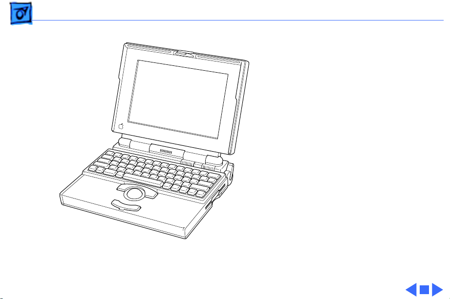
Overview
This manual includes
complete repair procedures
for the PowerBook 140,
PowerBook 145 and 145B,
and the PowerBook 170.
Figure: PowerBook 140, 145, 145B, 170
Page 4
Basics Display Compatibility Matrix - 2
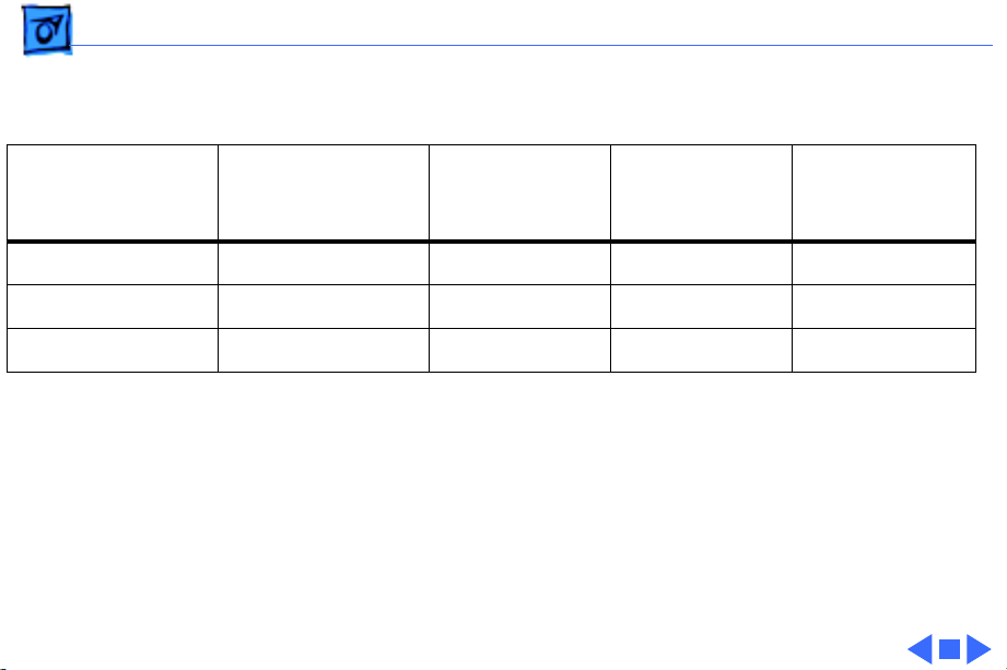
Display Compatibility Matrix
Active Matrix
PB 170
661-0711
Inverter 699-0273 699-0271 699-0272 922-0025
Display Cable 630-6273 922-0820 630-6272 922-0820
Inverter Cable 936-0106 936-0106 936-0106 936-0106
Important:
active matrix and three FSTN displays. Each of these
displays requires a compatible inverter and display cable;
the inverters, display cables, and displays are not
interchangeable. Before ordering a replacement display,
display cable, or inverter, refer to the display matrix.
FSTN, Rev. A
PB 140/145
661-0706
The PowerBook family includes four displays—an
FSTN, Rev. B
PB 140/145
661-0681
FSTN, Rev. C
PB 145/145B
661-0745
Page 5

Basics Displays - 3
Displays
Each of the four displays
requires a compatible
inverter and display cable.
Refer to the following pages
to identify the displays.
Page 6
Basics Displays - 4
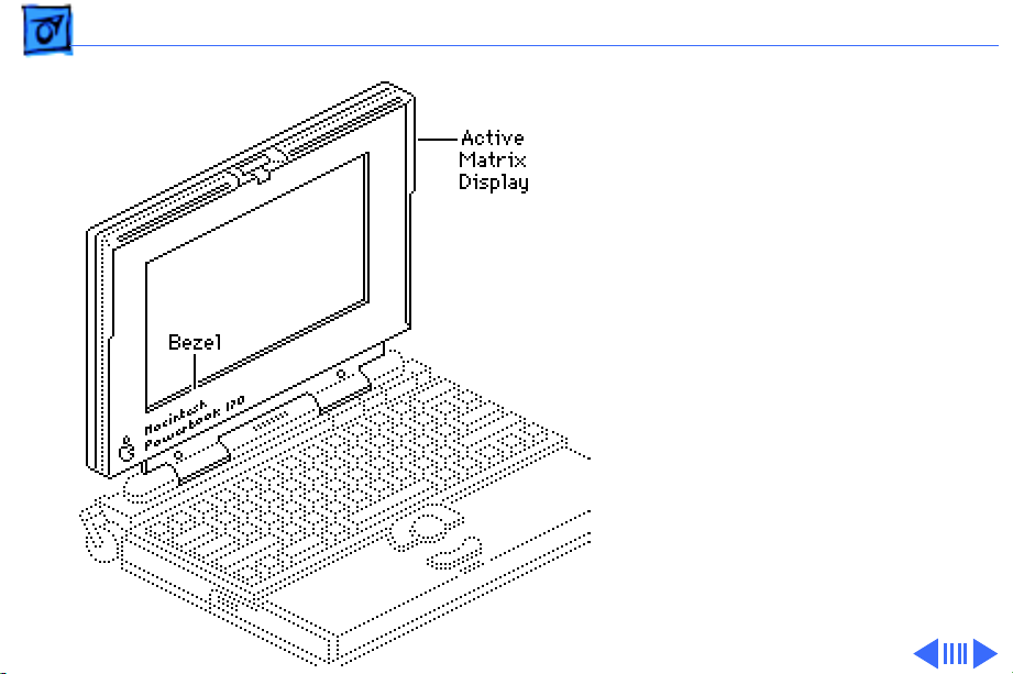
Active-Matrix Display
The active-matrix display is
available for the PowerBook
170 only. Use the following
replacement parts with the
PowerBook 170:
• Active Matrix Display
661-0711
• Inverter (green)
699-0273
• Display Cable
630-6273
• Inverter Cable
936-0106
Page 7
Basics Displays - 5
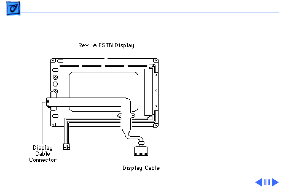
FSTN Display, Rev. A
Rev. A, B, and C FSTN
displays are available for
the PowerBook 140/145/
145B. The Rev. A display
has a plastic rear cover, and
the display cable connector
is located along the outside
edge of the printed circuit
board.
Page 8

Basics Displays - 6
If you are replacing the
inverter, display cable, or
Rev. A display in a
PowerBook 140/145, use
these replacement parts:
• FSTN Display, Rev. A
661-0706
• Inverter (blue)
699-0271
• Display Cable
922-0820
• Inverter Cable
936-0106
Page 9

Basics Displays - 7
FSTN Display, Rev. B
Rev. A, B, and C FSTN
displays are available for
the PowerBook 140/145/
145B. The printed circuit
board is exposed at the rear
of the Rev. B display, and the
display cable connector is
located near the center of the
board.
Page 10

Basics Displays - 8
If you are replacing the
inverter, display cable, or
Rev. B display in a
PowerBook 140/145, use
these replacement parts:
• FSTN Display, Rev. B
661-0681
• Inverter (red)
699-0272
• Display Cable
630-6272
• Inverter Cable
936-0106
Page 11
Basics Displays - 9
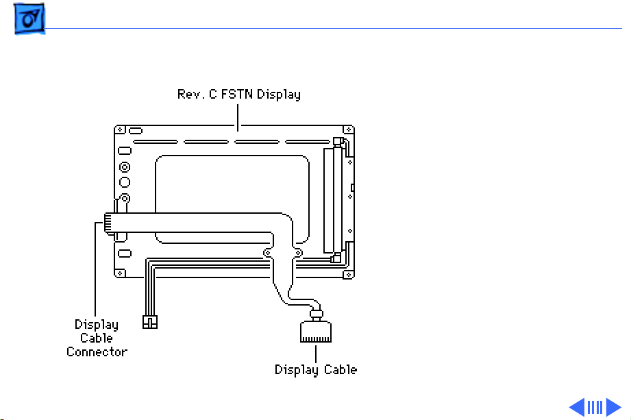
FSTN Display, Rev. C
Rev. A, B, and C FSTN
displays are available for
the PowerBook 140/145/
145B. The Rev. C display
has a plastic rear cover, and
the display cable connector
is located along the outside
edge of the printed circuit
board.
Page 12

Basics Displays - 10
If you are replacing the
inverter, display cable, or
Rev. C display in a
PowerBook 145/145B, use
these replacement parts:
• FSTN Display, Rev. C
661-0745
• Inverter (blue)
922-0025
• Display Cable
922-0820
• Inverter Cable
936-0106
Page 13

K
Service Source
Specifications
PowerBook 140/145/145B/170
Page 14

Specifications Processor - 1
Processor
140 CPU
145/145B/170 CPU
Coprocessor (170 Only)
Addressing
Motorola 68030 microprocessor
16 MHz
Motorola 68030 microprocessor
25 MHz
Motorola 68882 floating-point unit (FPU)
25 MHz
32-bit internal registers
32-bit address bus
32-bit data bus
Page 15

Specifications Memory - 2
Memory
RAM
RAM 145B
ROM
PRAM
VRAM
4 MB, 2 MB installed on the daughterboard and 2 MB on an
expansion card
Expandable to 6 MB by replacing 2 MB expansion card with 4 MB
card
4 MB pseudostatic RAM (PSRAM) installed on the daughterboard
Expandable to 8 MB by installing 4 MB expansion card
1 MB, expandable to 4 MB
256 bytes of parameter memory
256K of static video display memory
Page 16

Specifications Memory - 3
Clock/Calendar
Custom chip with long-life lithium battery
Page 17

Specifications Disk Storage - 4
Disk Storage
Floppy Drive
Hard Drive
19 mm high, 1.4 MB Apple SuperDrive
2.5 in., 40/80/120 MB hard drive
Page 18

Specifications I/O Interfaces - 5
I/O Interfaces
Floppy Drive
SCSI
Apple Desktop Bus
Serial
DB-19 serial port for connecting external floppy drives
HDI-30 SCSI port with 1.5 MB/sec. transfer rate
Supports up to five external SCSI devices
Does not provide termination power
Apple Desktop Bus (ADB) port (maximum of three ADB devices is
recommended)
200 mA maximum current draw for all ADB devices
Two RS-422 serial ports; mini DIN-8 connectors
Page 19

Specifications I/O Interfaces - 6
Sound
Monaural sound-in port
Stereo sound-out headphone jack that plays CD audio tracks in
stereo and computer-generated sounds in mono
Page 20

Specifications I/O Devices - 7
I/O Devices
Keyboard
Trackball
Microphone (140/ 145/170)
Built-in standard Apple keyboard
63 keys domestic; 64 keys ISO
Two-level tilt adjustment
30 mm diameter, dual button
ADB interface
Electret, omnidirectional
Output voltage of 4 mV, peak to peak
Page 21

Specifications Sound and Video - 8
Sound and Video
Video Display 140/ 145/145B
Video Display 170
Sound Generator
10 in. (254 mm) diagonal screen
Flat-panel, film-compensated supertwist nematic (FSTN) liquid
crystal display
CCFL on-demand backlight
640 by 400 pixels
10 in. (254 mm) diagonal screen
Flat-panel, active-matrix liquid crystal display
CCFL on-demand backlight
640 by 400 pixels
Apple sound chip provides 8-bit sound capable of driving stereo
headphones or other stereo equipment through the sound jack
Page 22

Specifications Electrical - 9
Electrical
Main Battery
PRAM Battery
Power Adapter
Nickel cadmium (NiCad), 2.5 Ah
Provides 2-3 hours of usage before recharging
Recharge time: 3 hours
500 power cycles capacity
3 V lithium
110–240 VAC line voltage
50–60 Hz
US, Japanese, United Kingdom, Australian, and European versions
Page 23

Specifications Physical - 10
Physical
Dimensions
Weight
Height: 2.25 in. (5.7 cm)
Width: 11.25 in. (28.6 cm)
Depth: 9.3 in. (23.6 cm)
6.8 lb. (3.1 kg) with battery
Page 24

Specifications Environmental - 11
Environmental
Operating Temperature
Storage Temperature
Relative Humidity
Altitude
50–104° F (10–40° C)
50–140° F (10–60° C)
20–80% noncondensing
0–15,000 ft. (0–4722 m)
Page 25

Specifications Other - 12
Other
Fax/Data Modem
Internal 2400-baud modem with fax send at 9600 baud (includes
fax send software)
300/1200/2400 bps transmission rates
Serial binary and asynchronous protocols
Fax communication: V.29
Error correction: V.42 and MNP 4
Data compression: V.42bis and MNP 5
Page 26

K
Service Source
Troubleshooting
PowerBook 140/145/145B/170
Page 27

Troubleshooting General/ - 1
General
The Symptom Charts included in this chapter will help you
diagnose specific symptoms related to your product. Because cures
are listed on the charts in the order of most likely solution, try
the first cure first. Verify whether or not the product continues to
exhibit the symptom. If the symptom persists, try the next cure.
(Note: If you have replaced a module, reinstall the original module
before you proceed to the next cure.)
If you are not sure what the problem is, or if the Symptom Charts
do not resolve the problem, refer to the Flowchart for the product
family.
For additional assistance, contact Apple Technical Support.
Page 28

Troubleshooting Power Manager Reset/ - 2
Power Manager Reset
Reset the power manager if the battery and power adapter are
proven good, but the computer will not power on. The computer
will not reset after a system crash.
To reset the power manager in a PowerBook 140/145/145B/
170,
• Remove the AC adapter and the battery.
• Let the unit sit without power hooked up for 3-5 minutes.
• Using two paper clips, simultaneously hold down the reset and
interrupt buttons for 5-10 seconds.
• Reinstall the battery and, if necessary, reconnect the AC
adapter.
• Turn on the computer.
Page 29

Troubleshooting Symptom Charts/Startup - 3
Symptom Charts
Startup
RAM failure occurs
(eight-tone error
chord sequence
sounds after startup
chord)
Hardware failure
occurs (four-tone
error chord sequence
sounds after startup
chord)
1 Replace RAM expansion card.
2 Replace daughterboard.
3 Replace motherboard.
1 Disconnect hard drive data cable and reboot system. If
startup sequence is normal, replace hard drive.
2 Disconnect floppy drive cable and reboot system. If startup
sequence is normal, replace floppy drive.
3 Replace motherboard.
Page 30

Troubleshooting Symptom Charts/Startup
(Continued)
- 4
Screen displays
checkerboard pattern;
no startup chime
Startup
1 Reseat RAM expansion card.
2 Replace RAM expansion card.
3 Replace daughterboard.
4 Reseat display cable.
(Continued)
Page 31

Troubleshooting Symptom Charts/Power - 5
Power
Screen is blank;
computer doesn’t
respond
1 Press reset switch.
2 Connect power adapter and reboot computer in 3–4 minutes.
3 Try known-good, charged main battery.
4 Check all interconnect board, daughterboard, and
motherboard connections.
5 Reset the power manager.
6 Replace keyboard.
7 Replace interconnect board.
8 Replace daughterboard.
9 Replace motherboard.
Page 32

Troubleshooting Symptom Charts/Power
(Continued)
- 6
After removing main
battery, some
Control Panel
settings are different
Power adapter is
plugged in, but
battery DA does not
indicate charger is
connected
Power
1 Replace interconnect board.
2 Replace daughterboard.
3 Replace motherboard.
1 Check battery charger connection.
2 Try known-good, charged main battery.
3 Try known-good power adapter.
4 Check battery thermistor cable connection.
5 Replace motherboard.
(Continued)
Page 33

Troubleshooting Symptom Charts/Power
(Continued)
- 7
Low-power warning
appears
Computer runs when
plugged in to wall
outlet but not on
battery power;
battery voltage is
within tolerance
Power
1 Recharge battery or attach power adapter.
2 Verify that peripherals are low-power.
3 Reduce use of power-consuming devices or connect power
4 Try known-good, charged main battery.
5 Try known-good power adapter.
6 Replace motherboard.
1 Reseat battery to make sure it is mating with contacts on
2 If motherboard includes removeable fuse, replace fuse.
3 Replace motherboard.
4 Return computer to Apple.
(Continued)
adapter.
motherboard.
Page 34

Troubleshooting Symptom Charts/Video - 8
Video
Pixel is always white 1 PowerBook 170, active matrix display only: If there are
more than five voids (pixels that are always white), or two
or more voids within one inch of each other, replace display
(CPRC/international repairers only) or return computer to
Apple.
2 PowerBooks 140, 145, and 145B, replace display.
Pixel is always black 1 PowerBook 170, active matrix display only: Replace display
(CPRC/ international repairers only) or return computer to
Apple.
2 PowerBooks 140, 145, and 145B, replace display.
Page 35

Troubleshooting Symptom Charts/Video
(Continued)
- 9
Row or partial row of
pixels never comes
on or is always on
Thin white line is
always on at middle of
screen
Video
1 Add shim to display cable. Refer to Additional Procedures.
2 Replace display cable.
3 Replace FSTN display (all repairers) or replace active-
4 Replace interconnect board.
5 Replace daughterboard.
For FSTN screens (PowerBook 140/145/145B), a thin white
line is normal. For active-matrix screens (PowerBook 170),
return display (CPRC/ international repairers only) or return
computer to Apple.
(Continued)
matrix display (CPRC/ international repairers only).
Page 36

Troubleshooting Symptom Charts/Video
(Continued)
- 10
Display is very light
or totally white
Video
1 Adjust screen contrast (PowerBook 140/145/145B only).
2 Check display cable, inverter board, interconnect board,
3 Replace inverter board.
4 Replace interconnect board.
5 Replace display cable.
6 Replace FSTN display (all repairers) or replace active-
7 Replace daughterboard.
8 Replace motherboard.
(Continued)
daughterboard, and motherboard connections.
matrix display (CPRC/ international repairers only).
Page 37

Troubleshooting Symptom Charts/Video
(Continued)
- 11
No display, but
computer appears to
operate correctly
Video
1 Adjust screen contrast.
2 Check display cable, inverter board, interconnect board,
3 Replace inverter board.
4 Replace interconnect board.
5 Add shim to display cable. Refer to Additional Procedures.
6 Replace power cable.
7 Replace display cable.
8 Replace FSTN display (all repairers) or replace active-
9 Replace daughterboard.
10 Replace motherboard.
(Continued)
daughterboard, and motherboard connections.
matrix display (CPRC/ international repairers only).
Page 38

Troubleshooting Symptom Charts/Video
(Continued)
- 12
Video
Rainbow colors
visible from extreme
viewing angles
Image is not uniform For FSTN screens (PowerBook 140/145/145B), irregularity in
Display stopped
working or dimmed
but is fine now
Such colors are normal for FSTN screens (PowerBook 140/145/
145B).
images is normal. Adjust contrast and brightness to diminish
effect. For active-matrix screens (PowerBook 170), replace
display (CPRC/ international repairers only) or return
computer to Apple.
If temperature is under 5 or over 40 degrees centigrade, this
reaction is normal for FSTN screens (PowerBook 140/145/
145B).
(Continued)
Page 39

Troubleshooting Symptom Charts/Video
(Continued)
- 13
Backlight doesn’t
operate
Video
1 Check cables.
2 Check display cable, inverter board, interconnect board,
3 Replace inverter board.
4 Replace inverter display cable.
5 Replace interconnect board.
6 Add shim to display cable. Refer to Additional Procedures.
7 Replace display cable.
8 Replace FSTN display (all repairers) or replace active-
9 Replace daughterboard.
10 Replace motherboard.
(Continued)
daughterboard, and motherboard connections.
matrix display (CPRC/ international repairers only).
Page 40

Troubleshooting Symptom Charts/Video
(Continued)
- 14
Video
Screen goes blank 1 Press any key to wake computer from system sleep.
2 Check display cable connection.
Two black horizontal
lines appear; screen
intermittently goes
dark
Screen flickers Add shim to display cable. Refer to Additional Procedures.
Add shim to display cable. Refer to Additional Procedures.
(Continued)
Page 41

Troubleshooting Symptom Charts/Floppy Drive - 15
Floppy Drive
Audio and video
present, but internal
drive does not operate
Disk ejects while
booting; display
shows Mac icon with
blinking X
1 Try known-good floppy disk.
2 Check floppy drive cable connection.
3 Replace floppy drive cable.
4 Replace floppy drive.
5 Replace daughterboard.
6 Replace motherboard.
1 Try known-good system disk.
2 Verify that trackball or mouse button is not stuck.
3 Check floppy drive cable connection.
4 Replace floppy drive cable.
5 Replace floppy drive.
6 Replace motherboard.
Page 42

Troubleshooting Symptom Charts/Floppy Drive
(Continued)
- 16
Floppy Drive
Disk does not eject 1 Switch off system and hold mouse button down while you
switch system on.
2 Insert opened paper clip into hole beside drive.
3 Check floppy drive cable connection.
4 Replace floppy drive cable.
5 Replace floppy drive.
6 Replace daughterboard.
7 Replace motherboard.
Disk initialization
fails
1 Verify using correct media.
2 Try known-good floppy disk.
3 Install inverter shield.
4 Check floppy drive cable connection.
5 Replace floppy drive cable.
6 Replace floppy drive.
(Continued)
Page 43

Troubleshooting Symptom Charts/Floppy Drive
(Continued)
- 17
Read/write/copy
error
Floppy Drive
1 Verify using correct media.
2 Try known-good floppy disk.
3 Install inverter shield.
4 Check floppy drive cable connection.
5 Replace floppy drive cable.
6 Replace floppy drive.
(Continued)
Page 44

Troubleshooting Symptom Charts/Hard Drive - 18
Hard Drive
Internal hard drive
does not operate
1 Disconnect external SCSI devices.
2 Check internal hard drive data cable connection.
3 Use HD SC Setup to reinitialize drive.
4 Replace internal hard drive data cable.
5 Replace internal hard drive.
6 Replace motherboard.
Page 45

Troubleshooting Symptom Charts/Peripherals - 19
Peripherals
After connecting
external SCSI device,
computer doesn’t boot
1 Switch on external SCSI device before starting computer.
2 Check cable connections.
3 Verify that standard Apple terminator terminates SCSI chain
at beginning and end.
4 Verify that SCSI select switch setting on external device is
unique.
5 Verify operation of internal hard drive.
6 Try known-good external SCSI device.
7 Replace motherboard.
Page 46

Troubleshooting Symptom Charts/Peripherals
(Continued)
- 20
Cursor does not move
when using trackball
Cursor intermittently
does not move or
moves erratically
Peripherals
1 Press reset switch.
2 Check interconnect board, daughterboard, and motherboard
connections.
3 Try low-power mouse. If cursor moves, replace trackball or
keyboard.
4 Replace interconnect board.
5 Replace daughterboard.
6 Replace motherboard.
1 Clean ball and rollers of trackball.
2 Replace trackball.
3 Replace keyboard.
4 Replace interconnect board.
5 Replace motherboard.
(Continued)
Page 47

Troubleshooting Symptom Charts/Peripherals
(Continued)
- 21
Cursor moves, but
clicking trackball
button has no effect
Cursor does not move
when using mouse
Peripherals
1 Check interconnect board, daughterboard, and motherboard
connections.
2 Replace trackball.
3 Replace keyboard.
4 Replace interconnect board.
5 Replace daughterboard.
6 Replace motherboard.
1 Check mouse connection to ADB port.
2 Press reset switch.
3 Clean mouse ball and inside mouse.
4 Replace mouse.
5 Replace motherboard.
(Continued)
Page 48

Troubleshooting Symptom Charts/Peripherals
(Continued)
- 22
No response to any
key on keyboard
Known-good
ImageWriter,
ImageWriter II, or
LQ does not print
Peripherals
1 Reset power manager.
2 Check connections of keyboard to interconnect board, and
interconnect board to daughterboard.
3 Replace keyboard.
4 Replace interconnect board.
5 Replace daughterboard.
1 Verify that System is 7.0.1 or later.
2 Verify that Chooser and Control Panel settings are correct.
3 Check cables.
4 Replace printer interface cable.
5 Try known-good printer.
6 Replace daughterboard.
7 Replace motherboard.
(Continued)
Page 49

Troubleshooting Symptom Charts/Peripherals
(Continued)
- 23
Known-good
LaserWriter does not
print
Device connected to
external modem port
doesn’t work
Peripherals
1 Verify that System is 7.0.1 or later.
2 Verify that Chooser and Control Panel settings are correct.
3 Check cables.
4 Replace printer interface cable.
5 Try known-good printer. If printer works, troubleshoot
network. Refer to Networks and Communications manual.
6 Replace daughterboard.
7 Replace motherboard.
1 Verify that External Modem is selected in CDEV.
2 Verify that System is 7.0.1 or later.
3 Check cables.
4 Attach device to known-good computer.
5 Replace daughterboard.
6 Replace motherboard.
(Continued)
Page 50

Troubleshooting Symptom Charts/Peripherals
(Continued)
- 24
I/O devices are
unrecognized or
garbage is
transmitted or
received
Peripherals
1 Verify that System is 7.0.1 or later.
2 Check cables.
3 Verify that SCSI device has standard Apple terminator.
4 Verify that SCSI select switch setting on external device is
unique.
5 Attach device to known-good computer.
6 Replace daughterboard.
7 Replace motherboard.
(Continued)
Page 51

Troubleshooting Symptom Charts/Internal Modem - 25
Internal Modem
Internal modem
options do not appear
in CDEV
Modem does not
respond properly to
AT command set
instructions
1 Remove and reseat modem card.
2 Verify that System is 7.0.1 or later.
3 Replace modem card.
4 Replace motherboard.
1 Verify that baud rate and data format settings of
communications application are compatible with internal
modem and remote modem.
2 Check phone cord connection and operation.
3 Remove and reseat modem card.
4 Verify that System is 7.0.1 or later.
5 Replace modem card.
Page 52

Troubleshooting Symptom Charts/Internal Modem
(Continued)
- 26
Strange mix of
characters appears
onscreen
Modem interferes
with system sound
Internal Modem
1 Verify that baud rate and data format settings of
communications application are compatible with internal
modem and remote modem.
2 Check phone cord connection and operation.
3 Remove and reseat modem card.
4 Verify that System is 7.0.1 or later.
5 Replace modem card.
6 Replace daughterboard.
7 Replace motherboard.
1 Remove and reseat modem card.
2 Replace modem board.
3 Replace interconnect card.
4 Replace motherboard.
(Continued)
Page 53

Troubleshooting Symptom Charts/Internal Modem
(Continued)
- 27
Modem does not
respond to incoming
call
Modem has no sound
output
Internal Modem
1 If computer is in sleep mode, verify that Wake On Ring
option in CDEV is selected.
2 Check phone cord connection and operation.
3 Replace modem card.
4 Replace motherboard.
1 Verify that Control Panel volume setting is above 0.
2 Replace modem card.
3 Replace interconnect card.
4 Replace motherboard.
(Continued)
Page 54

Troubleshooting Symptom Charts/Internal Modem
(Continued)
- 28
Modem connects but
does not communicate
with remote modem
Internal Modem
1 Verify that remote modem needs error correction (error
correction is internal modem default).
2 Type &Q0 to disable error correction.
(Continued)
Page 55

Troubleshooting Symptom Charts/Miscellaneous - 29
Miscellaneous
Screen goes blank and
computer shuts down
every few minutes
Application seems to
run slower after few
seconds
Hard disk is slow to
respond, or screen
goes blank too often
Adjust sleep delays in Control Panel or connect power adapter.
Connect power adapter.
Adjust sleep delays in Control Panel or connect power adapter.
Page 56

Troubleshooting Symptom Charts/Miscellaneous
(Continued)
- 30
No sound from
speaker
Miscellaneous
1 Verify that volume setting in Control Panel is 1 or above.
2 Check connections of speaker to interconnect board,
interconnect board to daughterboard, and daughterboard to
motherboard.
3 Replace interconnect board.
4 Replace daughterboard.
5 Replace motherboard.
(Continued)
Page 57

K
Service Source
T ak e Apart
PowerBook 140/145/145B/170
Page 58

Take Apart Main Battery - 1
Main Battery
Before you begin,
disconnect the power
adapter.
Note:
This procedure also
covers removal of the main
battery door.
Main Battery
Important:
the main battery, use the
Macintosh Shut Down
command. Otherwise, all
RAM contents will be lost.
Before removing
Page 59

Take Apart Main Battery - 2
±
Warning:
battery is a NICAD battery
that contains toxic
materials. Send undamaged,
dead batteries to Apple for
recycling—do not discard
dead batteries with other
waste. If the battery is
damaged, do not return it to
Apple. Dispose of damaged
batteries according to local
ordinances. Review battery
handling and disposal
instructions in Bulletins/
Safety.
The main
Page 60

Take Apart Main Battery - 3
1 Slide open the battery
door.
2 Using the battery door as
a handle, pull out the
main battery.
Page 61

Take Apart Main Battery - 4
3 Slide the battery door
completely open.
4 Pull the end tab until it
releases and remove the
door from the battery.
End Tab
Page 62

Take Apart I/O Door - 5
I/O Door
No preliminary steps are
required before you begin
this procedure.
I/O Door
Caution:
PowerBook140/145/170
contains CMOS devices that
are very susceptible to ESD
damage. To prevent damage,
wear a grounding
wriststrap. Review the ESD
precautions in Bulletins/
Safety.
The
Page 63

Take Apart I/O Door - 6
1 Open the I/O door.
2 Carefully bend the door
so that the middle bows
Right Door
Peg
outward and unhinge the
two bottom door pegs.
Page 64

Take Apart Top Case - 7
Top Case
Before you begin, remove
the following:
• Main battery
• I/O door
Top Case
Caution:
PowerBook140/145/170
contains CMOS devices that
are very susceptible to ESD
damage. To prevent damage,
wear a grounding
wriststrap.Review the ESD
precautions in Bulletins/
Safety.
The
Page 65

Take Apart Top Case - 8
1
Note:
Use a T-8 torx
driver to remove the
small screw from the
rear connector panel
and a T-10 torx driver
to remove the other case
screws.
Remove the five torx
screws from the bottom
case.
Page 66

Take Apart Top Case - 9
2 Lift up the top case and
disconnect the
interconnect cable.
3 Lift off the top case and
Interconnect
Ribbon
Cable
unhook the two tab
fasteners from the front
of the bottom case.
Tab Fastener
Replacement Caution:
When
connecting the interconnect
cable, fold the cable as
shown. If it is not folded
correctly, the cable could
short.
Page 67

Take Apart Hard Drive - 10
Hard Drive
Before you begin, remove
the following:
• Main battery
• I/O door
• Top case
• Modem card (if present)
Hard Drive
Caution:
PowerBook140/145/170
contains CMOS devices that
are very susceptible to ESD
damage. To prevent damage,
wear a grounding
wriststrap. Review the ESD
precautions in Bulletins/
Safety.
The
Page 68

Take Apart Hard Drive - 11
1
Caution:
The hard drive
ribbon cable is fragile.
Handle it with care.
Lift the locking tab on
connector J11 and
remove the hard drive
Locking
Tab
ribbon cable from the
motherboard.
J11 Connector
Page 69

Take Apart Hard Drive - 12
2 Using a T-8 torx driver,
remove the five screws
from the drive retainer.
3 Using a jeweler’s
screwdriver, release the
drive retainer latch and
remove the retainer.
Page 70

Take Apart Hard Drive - 13
4 Lift the hard drive out of
the bottom case.
5
Note:
If the hard drive
does not have a release
tab, carefully pry the
cable from the drive
with a screwdriver.
Release Tab
Pull the release tab and
disconnect the hard drive
cable.
Page 71

Take Apart Hard Drive - 14
Replacement Note:
retainers for 17-mm-high
and 19-mm-high hard
drives are not
interchangeable. Check the
height of the replacement
drive and use the
appropriate drive retainer.
For hard drive upgrades,
refer to Upgrades.
Replacement Note:
information on returning
drives, cables, and carriers
to Apple, refer to Additional
Procedures in the Hard
Drives manual.
Drive
For
Page 72

Take Apart Floppy Drive - 15
Floppy Drive
Before you begin, remove
the following:
• Main battery
• I/O door
Floppy Drive
• Top case
• Modem card (if present)
Caution:
140/145/170 contains
CMOS devices that are very
susceptible to ESD damage.
To prevent damage, wear a
grounding wriststrap.
Review the ESD precautions
in Bulletins/Safety.
The PowerBook
Page 73

Take Apart Floppy Drive - 16
1
Caution:
The floppy
drive ribbon cable is
fragile and should be
handled with care.
Lift the locking tab on
Locking
Tab
J9 Connector
connector J9 and remove
the floppy drive ribbon
cable from the
motherboard.
Page 74

Take Apart Floppy Drive - 17
2 Using a T-8 torx driver,
remove the five torx
screws from the drive
retainer.
3 Using a jeweler’s
screwdriver, release the
drive retainer latch and
remove the retainer.
Page 75

Take Apart Floppy Drive - 18
4 Lift the floppy drive out
of the bottom case.
5 Using a jeweler’s
screwdriver, push out
the locking tab and
remove the floppy drive
ribbon cable from the
drive.
Page 76

Take Apart Trackball Assembly - 19
Trackball Assembly
Before you begin, remove
the following:
• Main battery
Trackball
Assembly
• I/O door
• Top case
Caution:
PowerBook140/145/170
contains CMOS devices that
are very susceptible to ESD
damage. To prevent damage,
wear a grounding
wriststrap. Review the ESD
precautions in Bulletins/
Safety.
The
Page 77

Take Apart Trackball Assembly - 20
1
Trackball
Ribbon Cable
Locking
Tab
Caution:
ribbon cable is fragile
and should be handled
with care.
The trackball
Pull out the locking tab on
the trackball connector and
remove the trackball
ribbon cable.
Page 78

Take Apart Trackball Assembly - 21
2 Using a T-8 torx driver,
remove the two mounting
screws and lift the
trackball assembly out
of the top case.
Page 79

Take Apart Keyboard - 22
Keyboard
Before you begin, remove
the following:
• Main battery
• I/O door
Keyboard
• Top case
• Trackball assembly
Caution:
PowerBook140/145/170
contains CMOS devices that
are very susceptible to ESD
damage. To prevent damage,
wear a grounding
wriststrap. Review the ESD
precautions in Bulletins/
Safety.
The
Page 80

Take Apart Keyboard - 23
1
Caution:
The keyboard
ribbon cables are fragile
and should be handled
with care.
Keyboard
Ribbon Cables
Lift up the locking tabs
on the two keyboard
connectors and remove
the keyboard ribbon
cables.
Page 81

Take Apart Keyboard - 24
2 Using a T-8 torx driver,
remove the seven
mounting screws and
lift the keyboard out of
the top case.
Page 82

Take Apart Inverter Board - 25
Inverter Board
Before you begin, remove
the following:
• Main battery
• I/O door
• Top case
Inverter Board
Caution:
140/145/170 contains
CMOS devices that are very
susceptible to ESD damage.
To prevent damage, wear a
grounding wriststrap.
Review the ESD precautions
in Bulletins/Safety.
The PowerBook
Page 83

Take Apart Inverter Board - 26
Important:
matrix and three FSTN
displays are used with the
PowerBook 140/145/170
computers. Each display
requires a matching
inverter. When replacing a
display or inverter board,
refer to the “Display
Compatibility Matrix” in
Basics and to Service
Source parts database for
the correct part number for
each board.
One active-
Page 84

Take Apart Inverter Board - 27
1 If present, remove the
inverter shield.
Inverter Shield
2 Remove the two screws
and pull the inverter
board straight up to
Inverter
Cable
disconnect it from the
interconnect board.
Inverter
Board
3 Disconnect the inverter
cable.
Page 85

Take Apart Inverter Board - 28
Replacement Note:
inverter shields on all
PowerBook 140/145/170
computers. Inverter shields
are available on the Price
Pages. If you are replacing a
defective inverter that has
an inverter shield installed,
order both the inverter
board and the inverter
shield. Do not reuse the
original inverter shield.
Install
Page 86

Take Apart Inverter Board - 29
Brightness Pot Contrast Pot
Actuator Actuator
Inverter
Board
Replacement Note:
For
systems with FSTN displays,
be sure to align the
brightness and contrast pots
on the inverter board with
the plastic actuators on the
top case. It is easiest to align
the pots and actuators if you
set both to their extreme
outer positions.
Page 87

Take Apart Interconnect Board - 30
Interconnect Board
Before you begin, remove
the following:
• Main battery
• I/O door
• Top case
• Inverter board
Interconnect Board
Caution:
PowerBook140/145/170
contains CMOS devices that
are very susceptible to ESD
damage. To prevent damage,
wear a grounding
wriststrap.Review the ESD
precautions in Bulletins/
The
Page 88

Take Apart Interconnect Board - 31
Safety.
±
J3 Connector
J5 Connector
Warning:
interconnect board contains
hazardous materials.
Return bad interconnect
boards to Apple for proper
disposal.
1
Caution:
and display ribbon
cables are fragile.
Handle these cables with
care.
Lift up the locking tabs
on connectors J5 and J3
and remove the
keyboard ribbon cables.
The
The keyboard
Page 89

Take Apart Interconnect Board - 32
2 Pull out the locking tab
on connector J2 and
remove the display
cable.
Note:
If you also plan to
remove the display or the
display cable, separate the
Ferrite
Bead
display cable ferrite bead
from the top case. You may
need to use a small flatblade screwdriver to pry
off the ferrite bead.
J2 Connector
Replacement Note:
Connect
the display cable before
replacing the interconnect
board.
Page 90

Take Apart Interconnect Board - 33
3 Using a T-8 torx driver,
remove the two mounting
screws and lift the
interconnect board from
the top case.
Page 91

Take Apart Actuators - 34
Actuators
Before you begin, remove
the following:
• Main battery
• I/O door
• Top case
• Inverter board
Actuators
Caution:
PowerBook140/145/170
contains CMOS devices that
are very susceptible to ESD
damage. To prevent damage,
wear a grounding
wriststrap. Review the ESD
precautions in Bulletins/
Safety.
The
Page 92

Take Apart Actuators - 35
Note:
The PowerBook 170
has a brightness actuator
only (contrast is preset).
The PowerBook 140 has
both contrast and
brightness actuators.
Pull up and rotate the
actuator toward the display
to remove it from the top
case.
Page 93

Take Apart Elevation Feet - 36
Elevation Feet
Before you begin, remove
the following:
• Main battery
• I/O door
• Top case
Elevation Foot
Elevation Foot
Caution:
140/145/170 contains
CMOS devices that are very
susceptible to ESD damage.
To prevent damage, wear a
grounding wriststrap.
Review the ESD precautions
in Bulletins/Safety.
The PowerBook
Page 94

Take Apart Elevation Feet - 37
1 Using a T-8 torx driver,
remove the torx screw
and washer and the
spring clip from the
inside of the elevation
foot.
2 Pull off the elevation
Spring
Clip
Elevation
Foot
foot.
Page 95

Take Apart Daughterboard - 38
Daughterboard
Before you begin, remove
the following:
• Main battery
• I/O door
• Top case
• RAM expansion card (if
present)
Daughterboard
Page 96

Take Apart Daughterboard - 39
Logic Board
Take-Apart
Tool
Daughterboard
Motherboard
Caution:
The PowerBook
140/145/170 contains
CMOS devices that are very
susceptible to ESD damage.
To prevent damage, wear a
grounding wriststrap.
Review the ESD precautions
in Bulletins/Safety.
1 Using a T-8 torx driver,
remove the four
daughterboard mounting
screws.
Caution: Always use the
logic board take-apart tool
to separate the
daughterboard connector
from the motherboard
Page 97

Take Apart Daughterboard - 40
connector. Trying to
disconnect the
daughterboard from the
motherboard by rocking or
peeling the boards apart
damages the connectors.
2 Using the logic board
take-apart tool,
disconnect the
daughterboard from the
motherboard.
Note: For tools ordering
information, refer to
“Special Tools” in
Bulletins/Service Notices.
Page 98

Take Apart Motherboard - 41
Motherboard
Before you begin, remove
the following:
• Main battery
• I/O door
• Top case
• RAM expansion card (if
present)
• Daughterboard
• Modem board (if present)
Motherboard
Page 99

Take Apart Motherboard - 42
Floppy Drive Cable
Thermistor Cable
Locking Tab
Locking
Tabs
Hard Drive Cable
Caution: The PowerBook
140/145/170 contains
CMOS devices that are very
susceptible to ESD damage.
To prevent damage, wear a
grounding wriststrap.
Review the ESD precautions
in Bulletins/Safety.
1 Caution: The hard drive,
floppy drive, and
thermistor cables are
fragile. Handle them
with care.
Lift up the locking tabs
and remove the hard
drive, floppy drive, and
Page 100

Take Apart Motherboard - 43
Hex Nut Screw
Motherboard
battery thermistor
cables.
2 Remove the two hex nut
screws and lift the
motherboard out of the
bottom case.
 Loading...