

Page 1
Service Source
eMac (ATI Graphics)
Updated 15 July 2003
© 2003 Apple Computer, Inc. All rights reserved.
Page 2

eMac (ATI Graphics)
eMac -
1
Page 3
Service Source
Take Apart
eMac (ATI Graphics)
© 2003 Apple Computer, Inc. All rights reserved.
Page 4

Tools
The following tools are recommended for the take apart procedures.
• 2.5 mm hex (for rear housing)
• Nylon probe tools (922-5065)
• Phillips #1 screwdriver
• Phillips #2 screwdriver
• Jeweler’s screwdriver set
• Needlenose pliers
• ESD wriststrap and mat
• CRT discharge tool
Note:
Do not use a power driver on the rear housing screws.
Tools
eMac (ATI Graphics) Take Apart -
1
Page 5
CRT Neck/Display/Analog Assembly Handling Information
Handling
Important:
when working with the display/analog assembly.
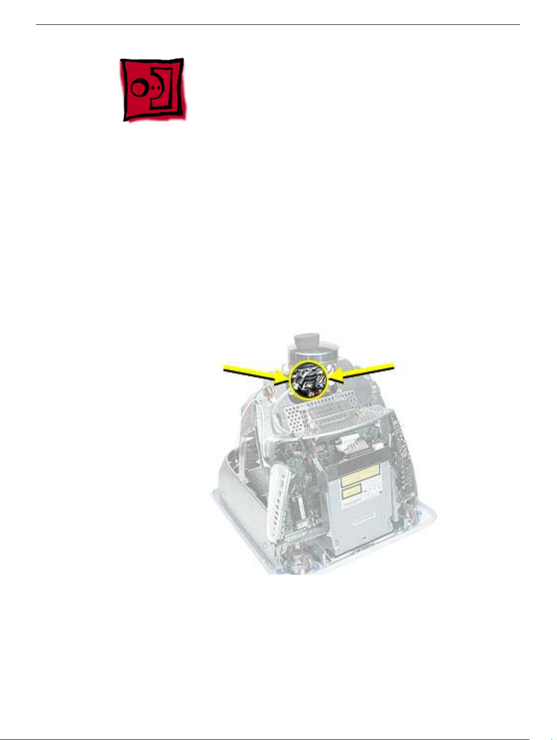
Do NOT lift, handle, bump, or manipulate the CRT neck/neck board (see arrows below) on
the Display/Analog assembly. Modules damaged by mishandling are NOT covered by
Apple Warranty. Apple Authorized Service Providers can be liable for broken CRT necks
due to improper handling.
Caution
handling the assembly. Lift the assembly from the metal chassis; never lift the assembly
from the neck. I
It is imperative that proper handling and packaging guidelines be followed
: The metal chassis has sharp edges, you may want to wear gloves when
Packing a Defective Display/Analog Assembly
The packing procedure is included with the replacement display/analog assembly.
Incorrect packaging can result in damaged eMac (ATI Graphics) displays. Please read and
follow the directions enclosed in the shipping box of the new display prior to packaging the
defective assembly. AASPs can be liable for broken CRT necks due to improper packing
and handling.
2
eMac (ATI Graphics) Take Apart
CRT Neck/Display/Analog Assembly Handling Infor-
Page 6
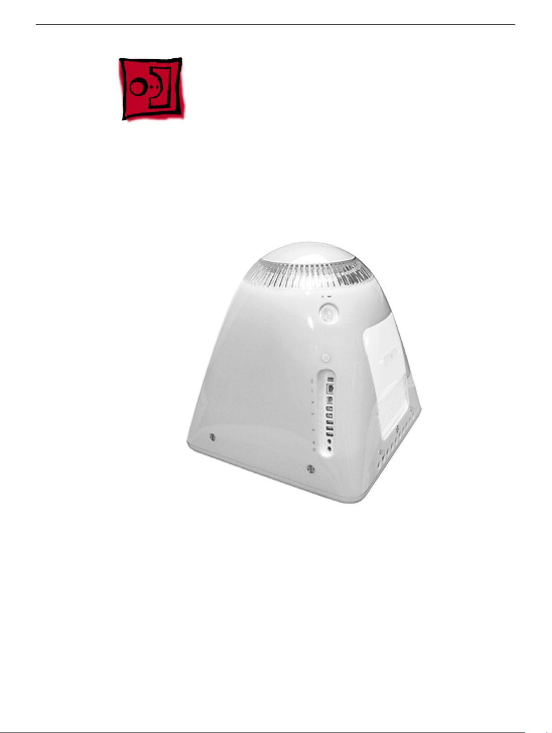
Rear Housing
Tools
• 2.5 mm hex (for the rear housing)
• Phillips #2 screwdriver
Part Location
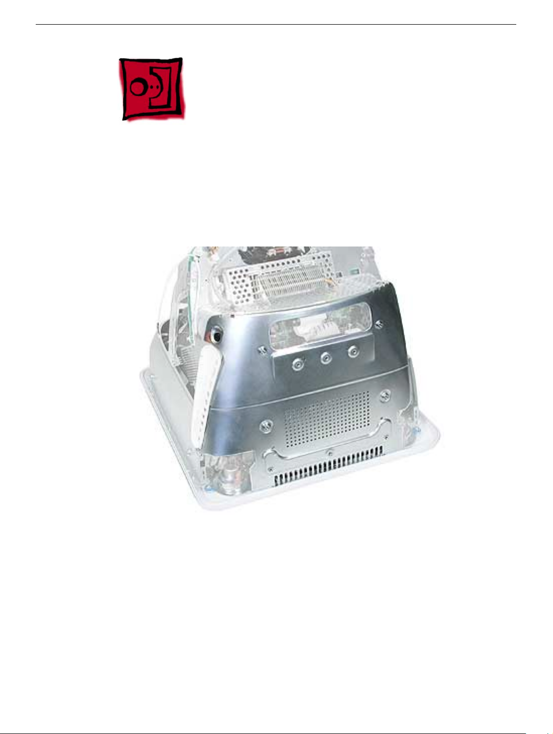
Rear Housing
Preliminary Steps
Before you begin, do the following:
• Place the computer face down on an ESD mat.
eMac (ATI Graphics) Take Apart -
3
Page 7
Procedure
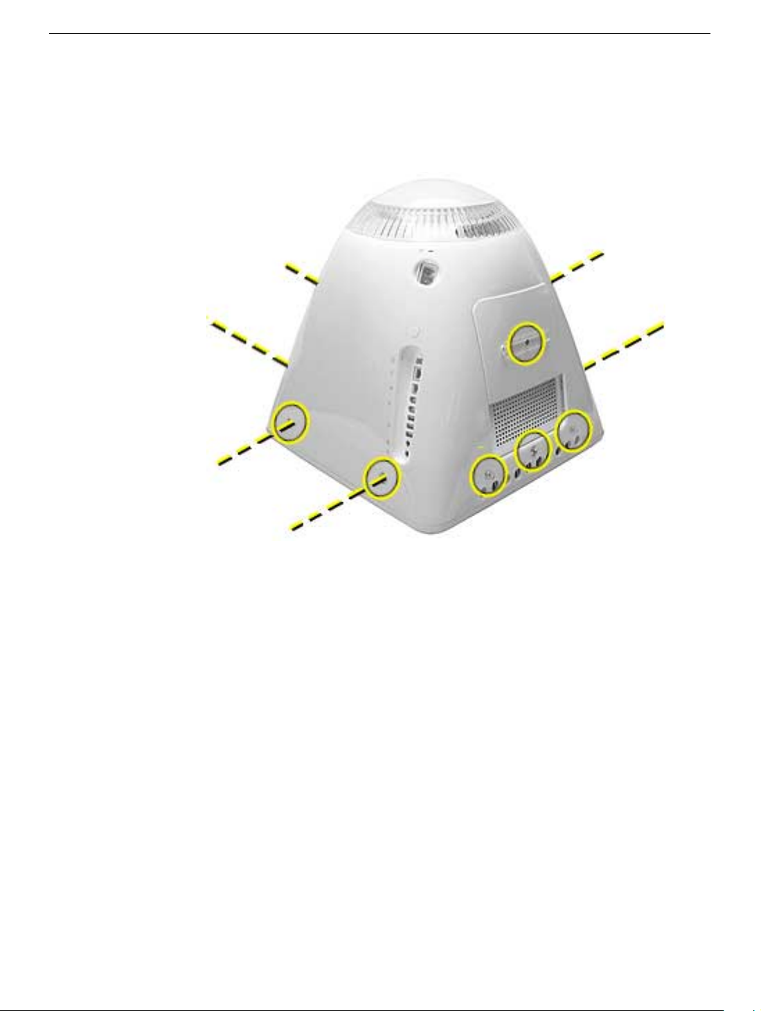
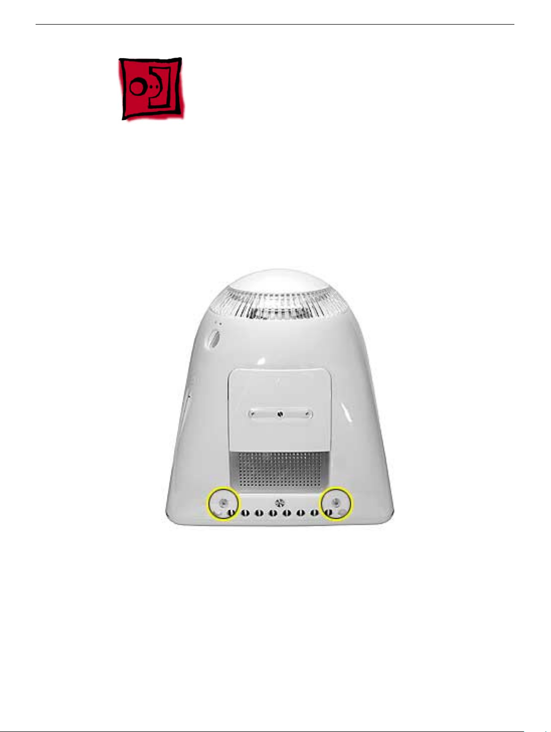
1. Remove ten screws. Seven screws on the rear housing, one screw on the user access
door (requires Phillips screwdriver), and two screws for the feet (requires Phillips
screwdriver).
4
eMac (ATI Graphics) Take Apart
Rear Housing
Page 8
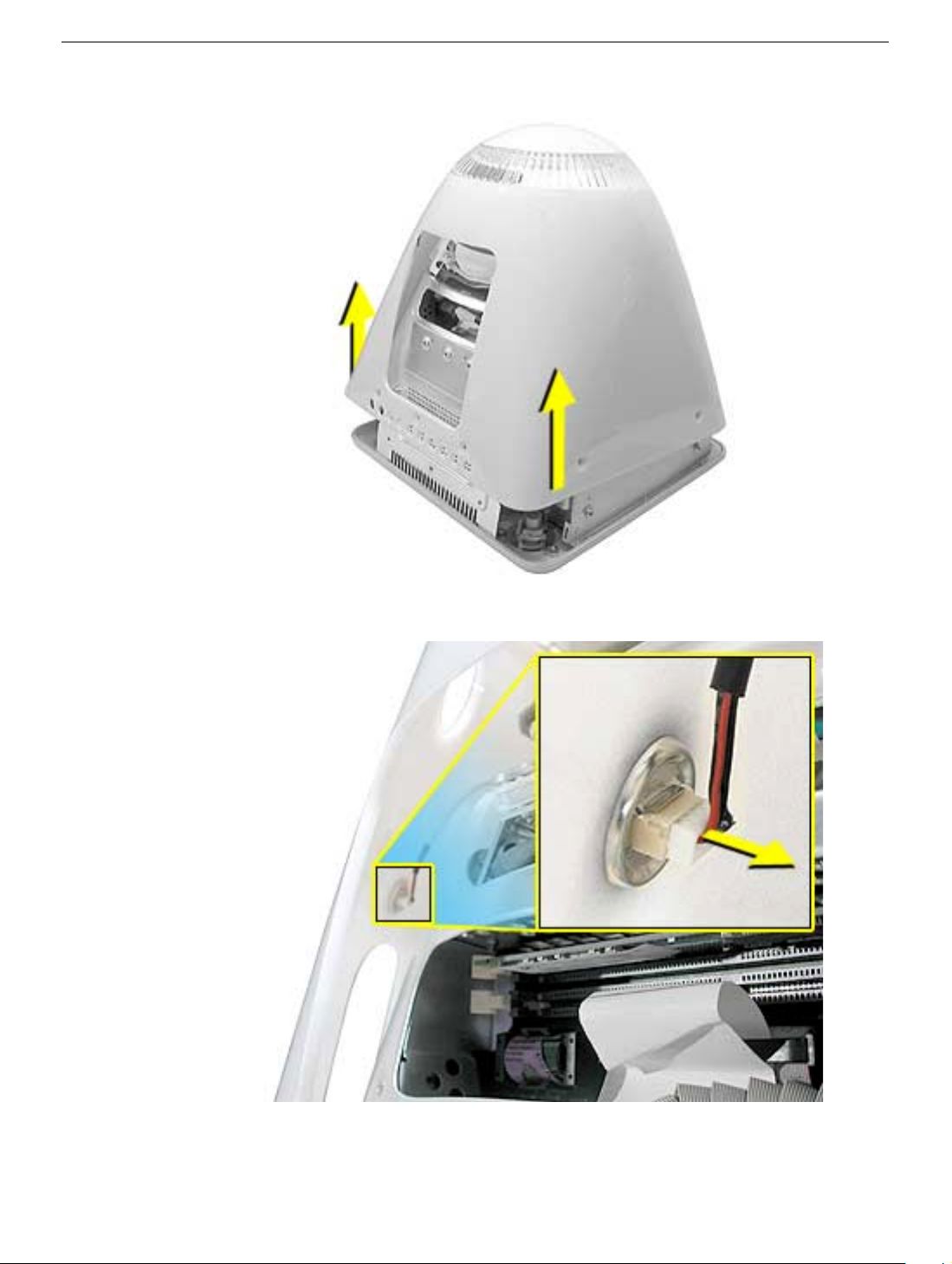
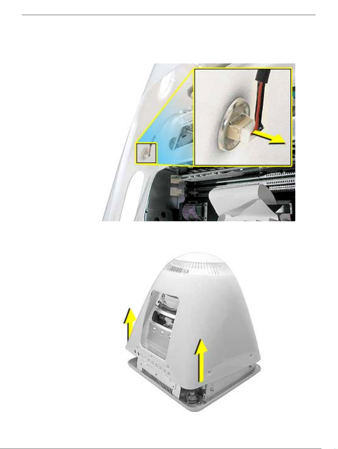
2. Gently lift the rear housing up about four inches.
3. Disconnect the power button cable located on the inside the rear housing.
Rear Housing
4. Lift the rear housing off the computer.
eMac (ATI Graphics) Take Apart -
5
Page 9
User Access Door
Tools
This procedure requires the following tools:
• Phillips #2 screwdriver
Part Location
Preliminary Steps
Before you begin, do the following:
• Place the computer face down on an ESD mat.
6
eMac (ATI Graphics) Take Apart
User Access Door
Page 10
Procedure
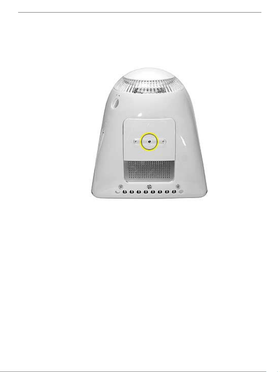
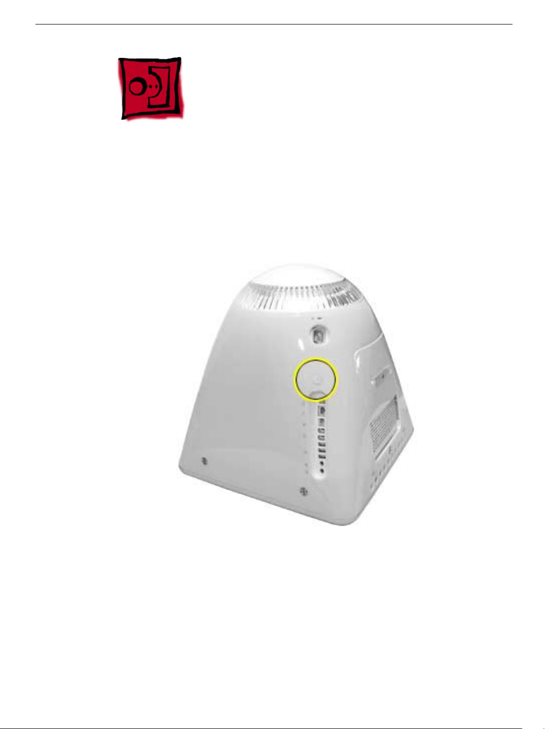
1. Remove the screw on the user access door (shown below).
2. Gently remove the access door.
User Access Door
eMac (ATI Graphics) Take Apart -
7
Page 11
Feet
Tools
This procedure requires the following tools:
• Phillips #2 screwdriver
Part Location
Preliminary Steps
Before you begin, do the following:
• Place the computer face down on an ESD mat.
8
eMac (ATI Graphics) Take Apart
Feet
Page 12
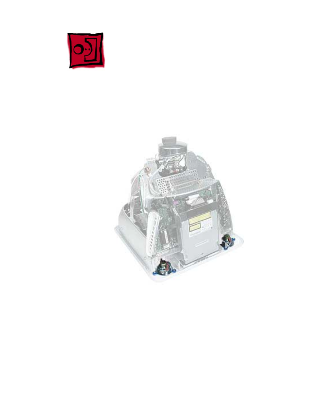
Procedure
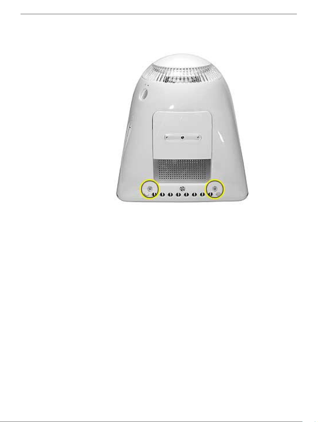
1. Remove the two foot screws. Set the plastic feet aside.
Feet
eMac (ATI Graphics) Take Apart -
9
Page 13
Power Button
Tools
• Needlenose pliers
Note:
Follow the Replacement Note procedure (step 2) only if you are replacing a
defective power button.
Part Location
Preliminary Steps
Before you begin, do the following:
• Place the computer face down on an ESD mat.
• Remove the user access panel.
• Remove the feet.
• Remove the rear housing.
10
eMac (ATI Graphics) Take Apart
Power Button
Page 14
Procedure
1. Disconnect the power button cable from the power button located inside the rear
housing.
2. Lift the rear housing off the bezel.
page, “Power Button Cable Check” before replacing the rear housing.
Replacement Note:
Refer to the topic on the next
Power Button
eMac (ATI Graphics) Take Apart -
11
Page 15
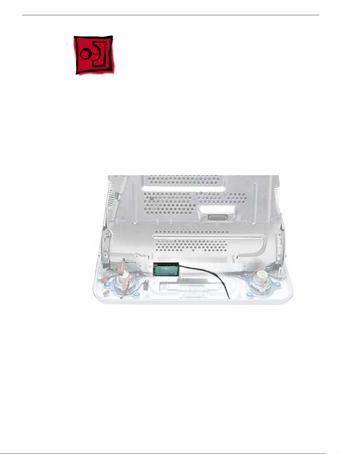
Power Button Cable Check
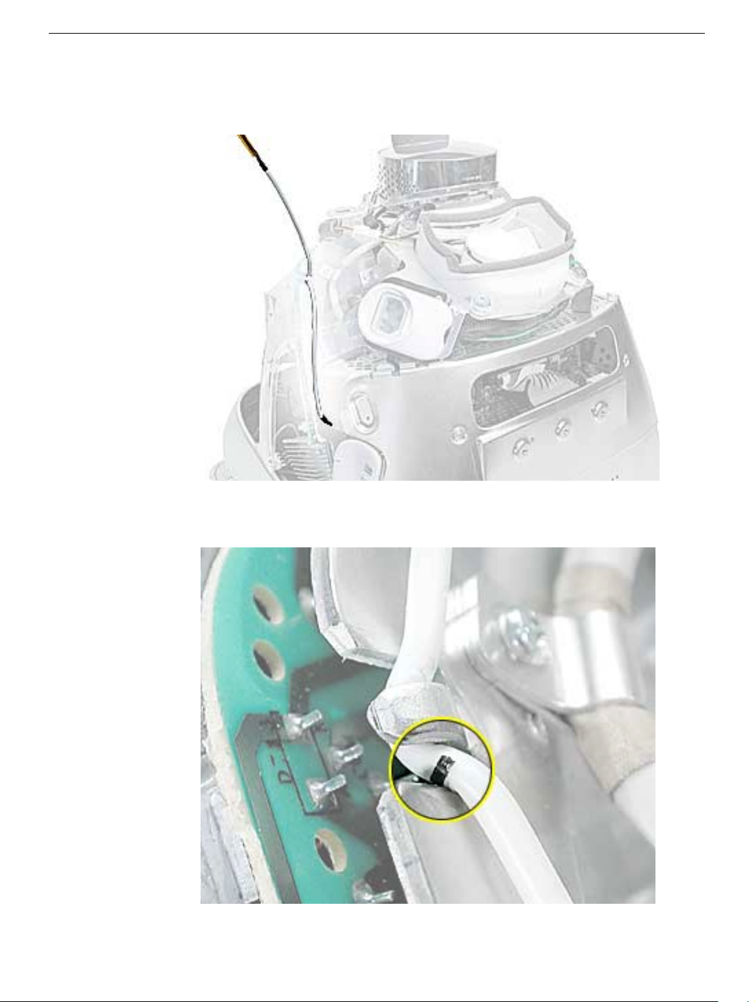
1. Check that the power button cable in drawn tight before you attach the other end of the
cable to the power button (located inside the rear housing).
2. Also, check that the cable is tucked under the chassis tab (as shown) and that the
black mark on the cable lines up with the chassis (circled below).
12
eMac (ATI Graphics) Take Apart
Power Button
Page 16
Power Button Replacement
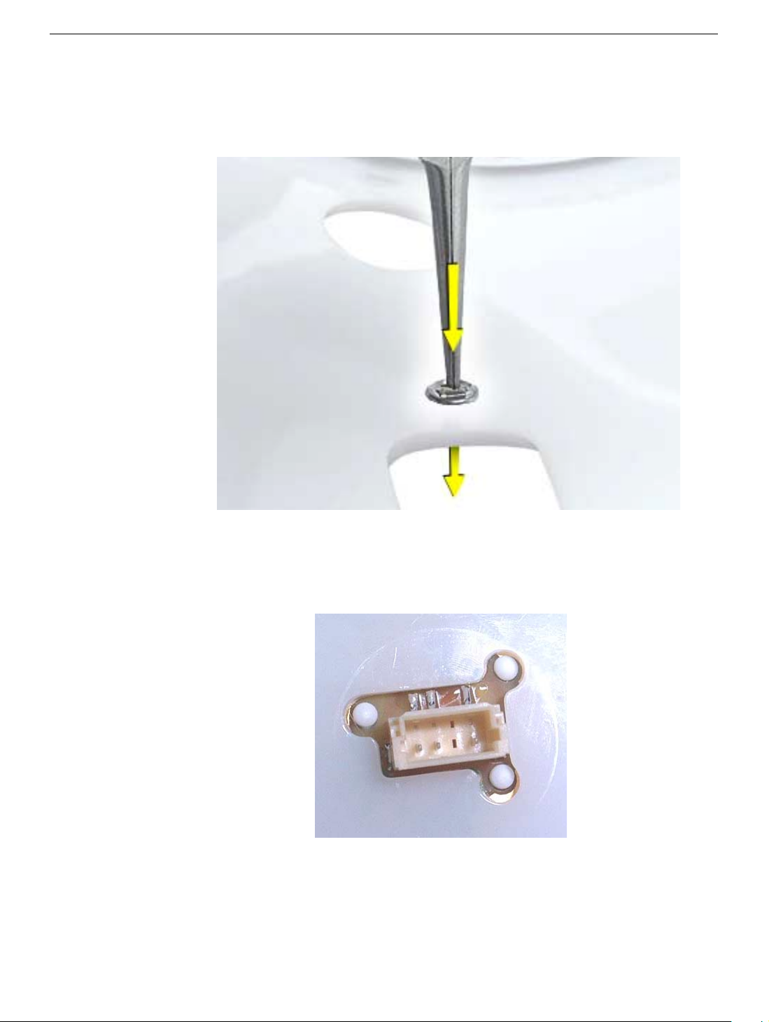
1. Continue with this procedure only if you are replacing a defective power button. With a
needlenose pliers, push the power button through the retaining ring. The power button
will pop off rear housing and the retaining ring may get stuck on the pliers.
2. Obtain the new power button and peel the sticky backing off the power button. Position
the power button into the hole on the rear housing (as shown below).
picture below is looking at the power button from the inside of the rear housing.
3. Place the retaining ring over the power button connector and press down firmly.
Note:
The
Power Button
eMac (ATI Graphics) Take Apart -
13
Page 17
CRT Discharge
Warning:
injury, always review the Service Foundations: CRT Displays course for safety information.
It can be found at: http://service.info.apple.com/service_training/training.html. Click on
Desktop Certification Courses and select the Service Foundations: CRT Displays link.
Warning:
an ongoing ground connection.
This product contains high voltage and a high-vacuum picture tube. To prevent
Never use a grounding wriststrap until after discharging the CRT and setting up
Safety Guidelines:
Whenever the rear housing of the computer is removed and before replacing a module,
you must
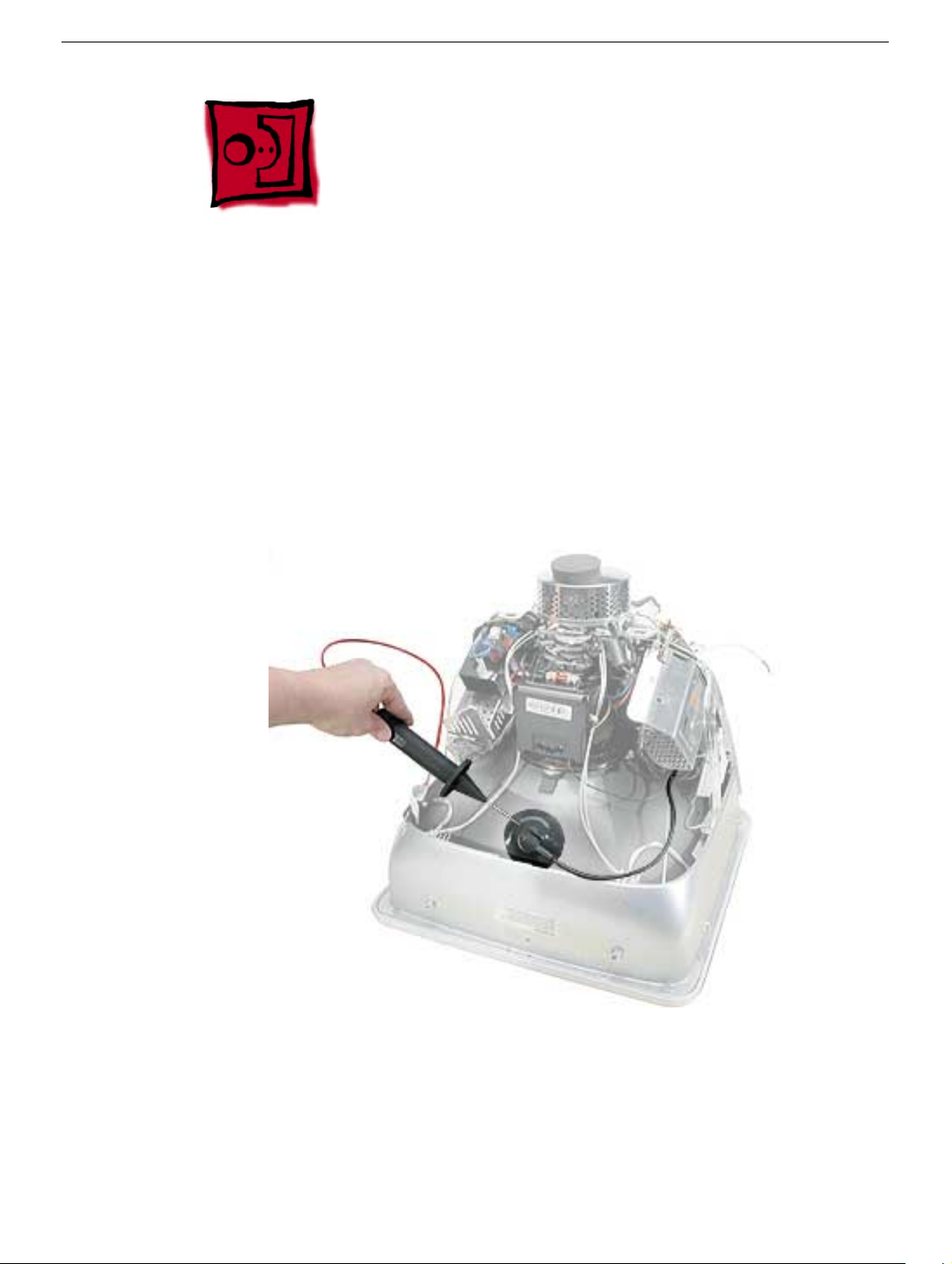
1. Discharge the CRT (shown below) and remove the anode cap.
2. Establish an ongoing ground by using a cable with alligator clips at both ends.
Connect one end to the anode aperture, and connect the other end to the metal CRT
frame (as shown below).
3. With the CRT discharged and the ongoing ground in place wear a grounding
wriststrap to prevent equipment damage from static electricity.
14
eMac (ATI Graphics) Take Apart
CRT Discharge
Page 18
Speakers
Tools
This procedure requires the following tools:
• Phillips #2 screwdriver
Part Location
Speakers
Preliminary Steps
Before you begin, do the following:
• Place the computer face down on an ESD mat.
• Remove the user access door.
• Remove the feet.
• Remove the rear housing.
• Discharge the CRT.
eMac (ATI Graphics) Take Apart -
15
Page 19
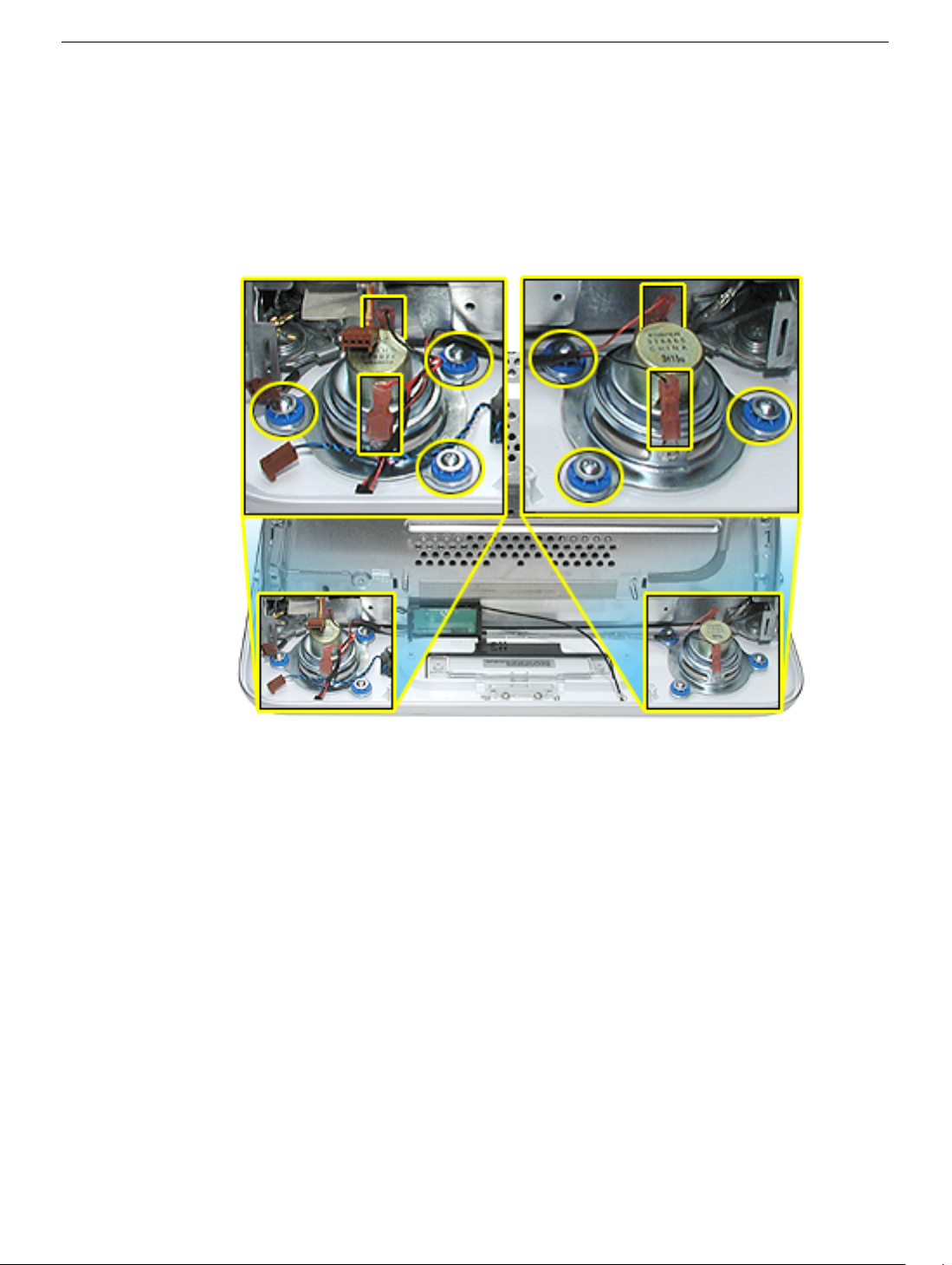
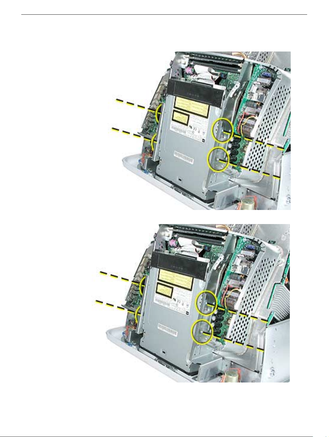
Procedure
1. Remove the left and right speaker screws (circled in the top photos). There are three
screws per speaker.
2. Disconnect the two spade connectors (see rectangles in the top photos) on each
speaker.
3. Lift the speakers out of the front bezel.
16
eMac (ATI Graphics) Take Apart
Speakers
Page 20
Fan
Tools
This procedure requires the following tools:
• Phillips #2
Part Location
Fan
Preliminary Steps
Before you begin, do the following:
• Place the computer face down on an ESD mat.
• Remove the user access door.
• Remove the feet.
• Remove the rear housing.
• Discharge the CRT.
eMac (ATI Graphics) Take Apart -
17
Page 21
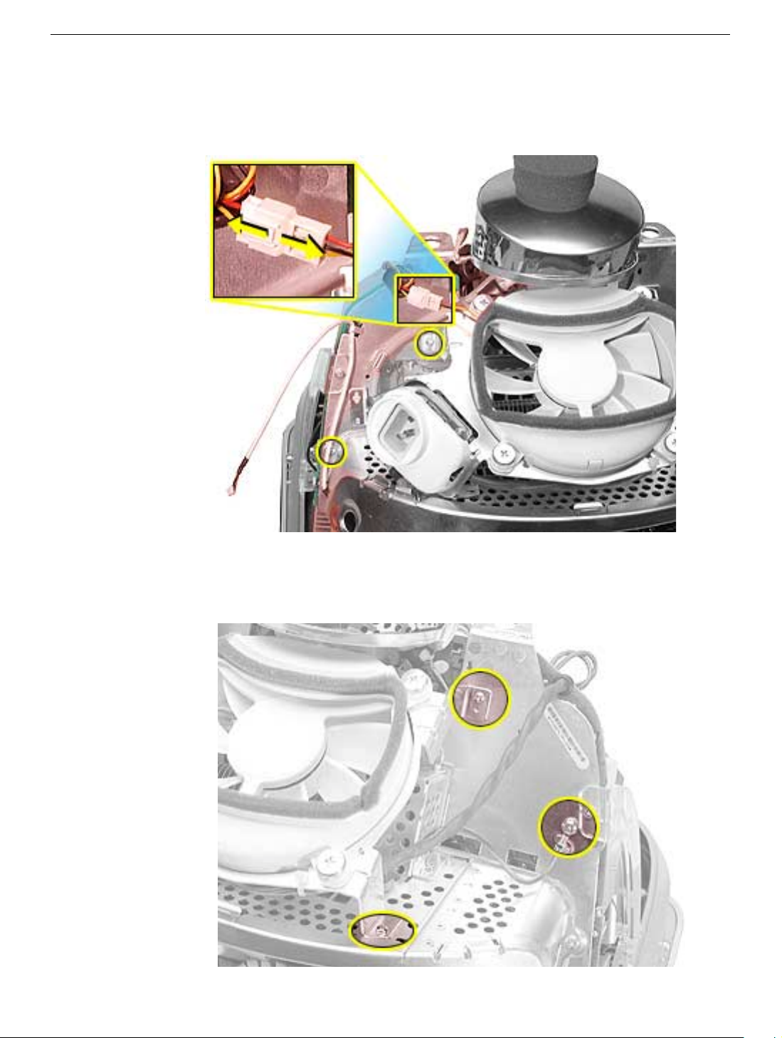
Procedure
1. On the left side of the fan, disconnect the fan cable and remove the two screws
(circled).
2. On the right side of the fan, remove three screws (the green cable goes to the ground
screw).
and the screw on the bottom left is a fine thread screw.
Replacement Note:
The screw circled on the top left is a self-tapping screw,
18
eMac (ATI Graphics) Take Apart
Fan
Page 22
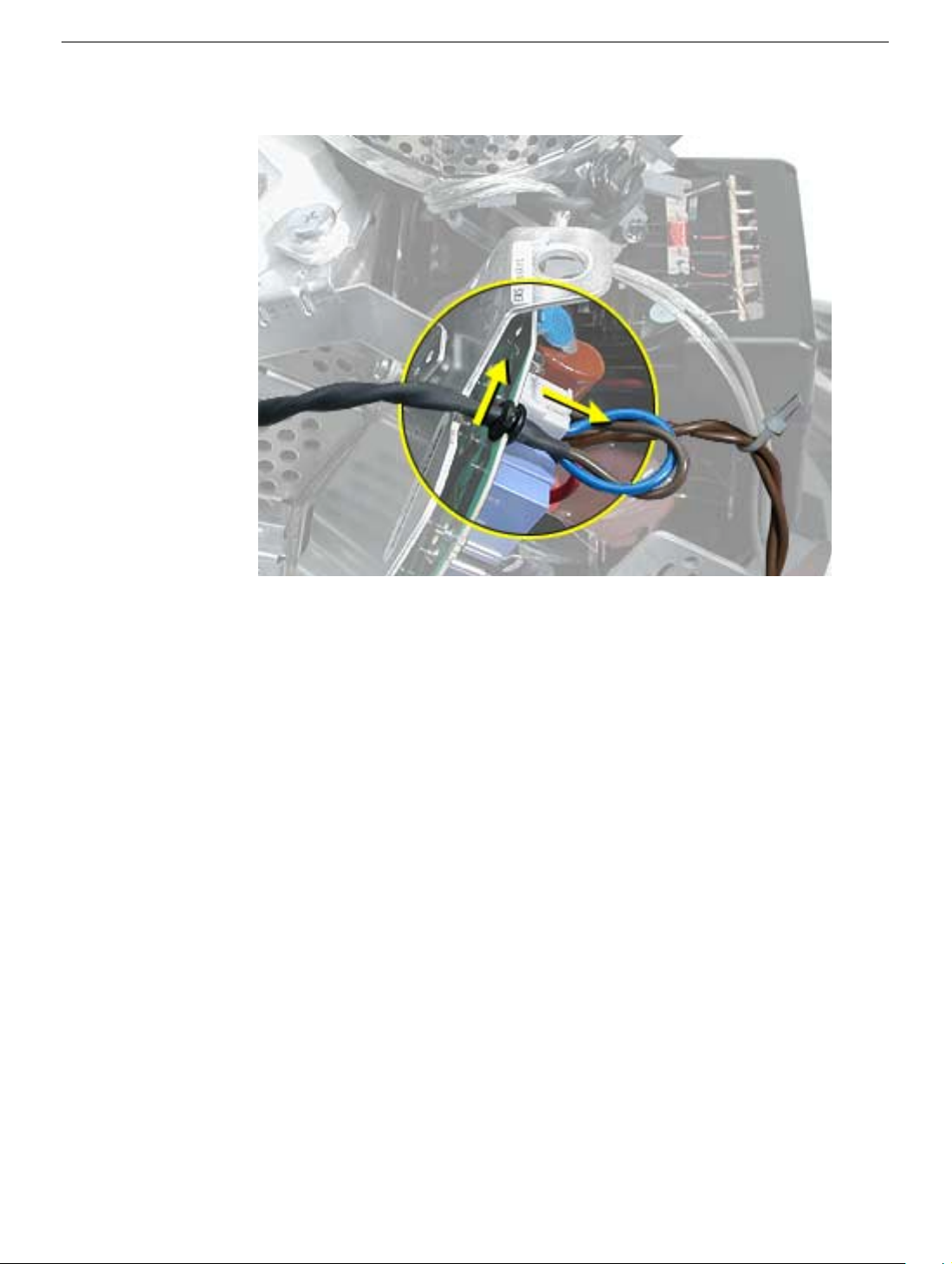
3. Wiggle the fan cable up and out of the groove in the chassis and then disconnect the
fan connector from the board.
4. To remove the fan, turn the computer so the fan is facing you. Grab onto the fan near
the AC plug and the bottom right corner of the fan. Gently pull the fan toward you and
away from the chassis. Be very careful of the CRT neck.
Fan
eMac (ATI Graphics) Take Apart -
19
Page 23
Faraday Plate
Tools
This procedure requires the following tools:
• Phillips #2
Part Location
Preliminary Steps
• Place the computer face down on an ESD mat.
• Remove the user access door.
• Remove the feet.
• Remove the rear housing.
• Discharge the CRT.
20
eMac (ATI Graphics) Take Apart
Faraday Plate
Page 24
Procedure
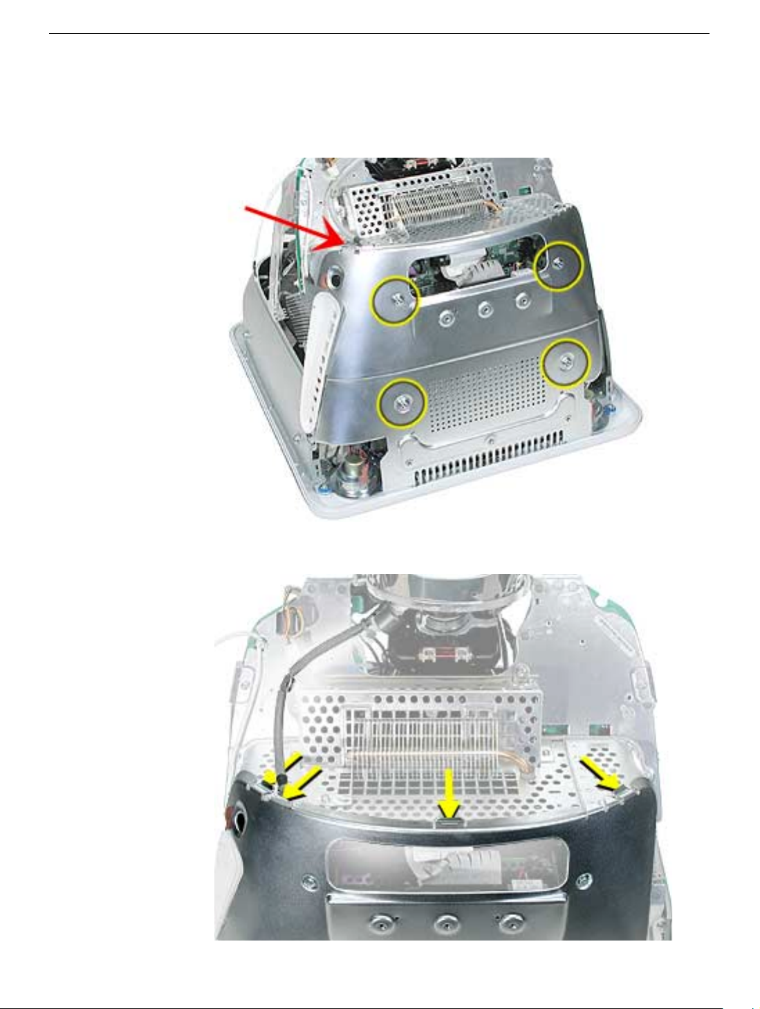
1. Remove the four screws on the Faraday plate.
of the gray cable (see red arrow) on the top left side of the Faraday plate. Be careful
the cable doesn’t get pinched when the Faraday plate is replaced.
Replacement Note:
Note the position
2. Gently pry the top half of the Faraday plate away from the chassis in the direction of
the arrows.
Note:
The gray cable (on left) rests in a groove under the Faraday plate.
Faraday Plate
eMac (ATI Graphics) Take Apart -
21
Page 25
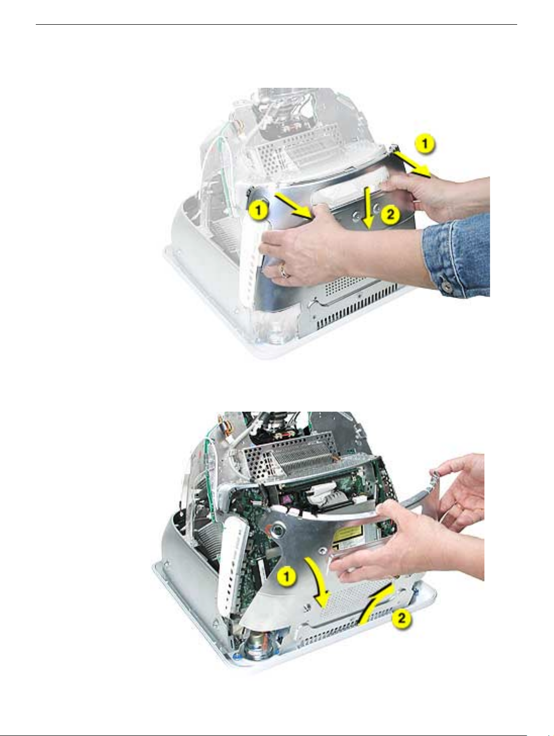
3. Pull the Faraday plate back (#1) and then push it down (#2) to unhook the metal tabs
on the Faraday plate from the cutouts (see graphic on the next page) in the chassis.
4. Continue to pull the Faraday plate back (#1) to unhook the tabs from the chassis. Pull
the Faraday plate up (#2) to remove it from the chassis.
22
eMac (ATI Graphics) Take Apart
Faraday Plate
Page 26
Faraday Replacement
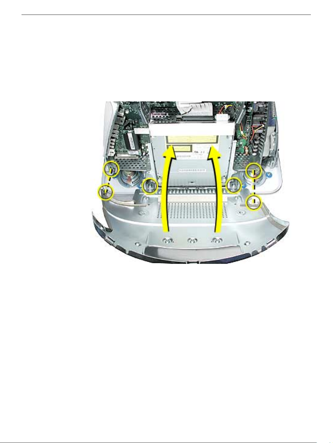
1. Looking from the top down, line up the metal tabs with the cutouts in the chassis
(circled on the right and left) and the slots on the Faraday plate with the white plastic
guides on the bezel (circled on the right and left sides of the optical drive).
2. Raise the Faraday plate up and attach it to the frame on the digital assembly. Be
careful that the gray cable (shown in step 2 on the previous page) does not get
pinched in the Faraday plate.
Faraday Plate
eMac (ATI Graphics) Take Apart -
23
Page 27
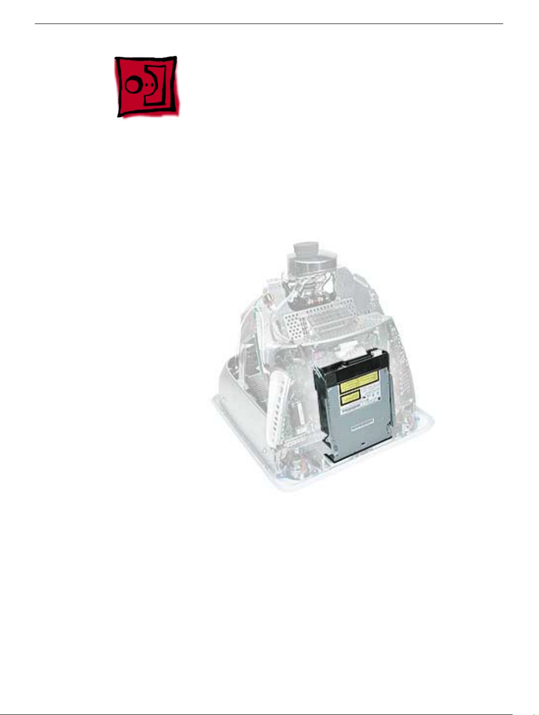
Optical Drive
Tools
This procedure requires the following tools:
• Phillips #2 screwdriver
Part Location
Preliminary Steps
Before you begin, do the following:
• Place the computer face down on an ESD mat.
• Remove the user access door.
• Remove the feet.
• Remove the rear housing.
• Discharge the CRT.
• Remove the Faraday plate.
24
eMac (ATI Graphics) Take Apart
Optical Drive
Page 28
Procedure
1. Disconnect the data cable and the power cable at the top of the optical drive.
2. Remove the four screws connecting the optical drive to the chassis.
3. Holding the optical drive by the top or bottom end, tilt the optical drive out of the
chassis.
Place the EMI shield on the replacement drive.
Replacement Note:
Remove the EMI shield on the end of the optical drive.
Optical Drive
eMac (ATI Graphics) Take Apart -
25
Page 29
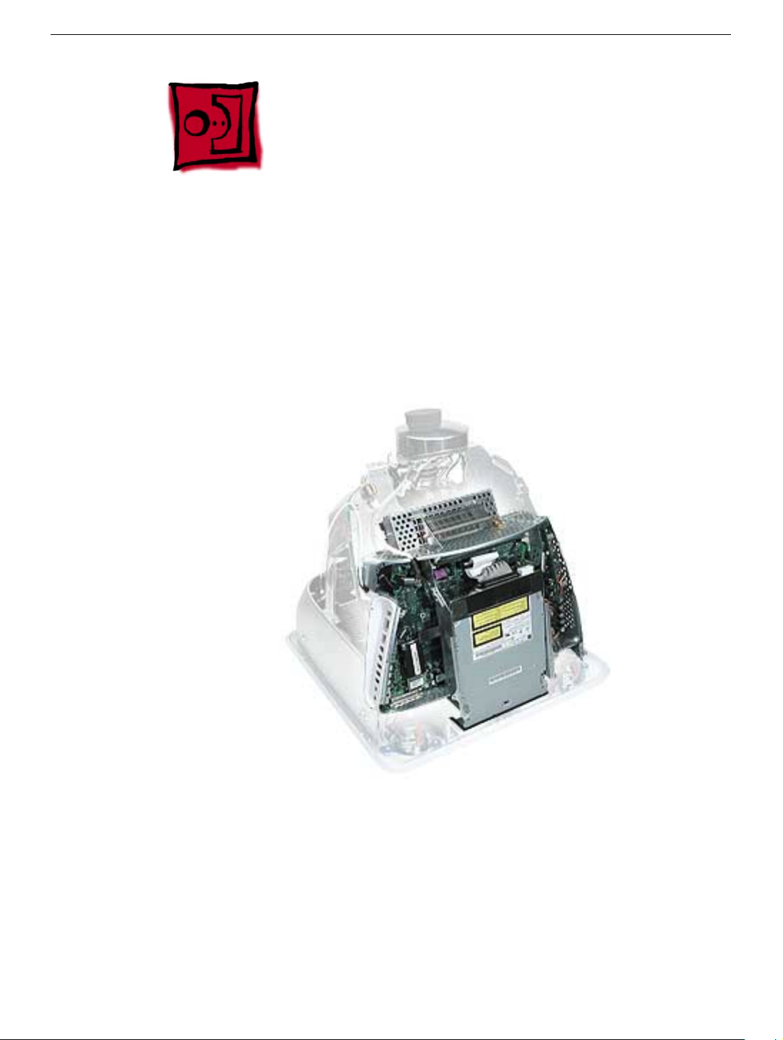
Digital Assembly
Tools
This procedure requires the following tools:
• Phillips #2
Part Location
Preliminary Steps
Before you begin, do the following:
• Place the computer face down on an ESD mat
• Remove the user access door
• Remove the feet
• Remove the rear housing
• Discharge the CRT
26
eMac (ATI Graphics) Take Apart
Digital Assembly
Page 30

• Remove the fan
• Remove the Faraday plate
• Remove the AirPort Extreme Card (if present)
Digital Assembly
eMac (ATI Graphics) Take Apart - 27
Page 31

Procedure
1. With the back of the computer facing you, remove the three screws near the top of the
digital assembly.
2. Disconnect the power button cable and the video cable on the top left side of the
digital assembly.
28 eMac (ATI Graphics) Take Apart
Digital Assembly
Page 32

3. Remove two screws; one on each side of the digital assembly.
4. On the bottom left side of the digital assembly, remove three screws.Note: The two
screws (at the top of this photo) are the same type screw; the third screw is a larger,
self-tapping screw that attaches to the front bezel.
Digital Assembly
eMac (ATI Graphics) Take Apart - 29
Page 33

5. Disconnect the four cable connectors on the bottom left side of the assembly. From left
to right the connectors are: microphone, fan, LED, and speakers.
6. Remove the two screws on the bottom right side of the assembly. Note: The screw
that attaches to the plastic bezel is a larger, self-tapping screw.
30 eMac (ATI Graphics) Take Apart
Digital Assembly
Page 34

7. Hold the digital assembly by the sides and pull the assembly straight back. The digital
assembly disconnects from the blind mate connector (circled) on the chassis. Set the
digital assembly aside.
Digital Assembly
eMac (ATI Graphics) Take Apart - 31
Page 35

Hard Drive
Tools
This procedure requires the following tools:
• Phillips #2
• Phillips #1
Part Location
Preliminary Steps
Before you begin, do the following:
• Place the computer face down on an ESD mat.
• Remove the user access door.
• Remove the feet.
• Remove the rear housing.
• Discharge the CRT.
32 eMac (ATI Graphics) Take Apart
Hard Drive
Page 36

• Remove the fan.
• Remove the Faraday plate.
• Remove the digital assembly.
Hard Drive
eMac (ATI Graphics) Take Apart - 33
Page 37

Procedure
1. Remove the four screws along the back of the metal chassis. Note: The two outer
screws are fine thread screws.
2. Gently unhook (see circle) and lift the hard drive carrier up and off the chassis. Flip the
drive carrier over to access the data and power cables.
34 eMac (ATI Graphics) Take Apart
Hard Drive
Page 38
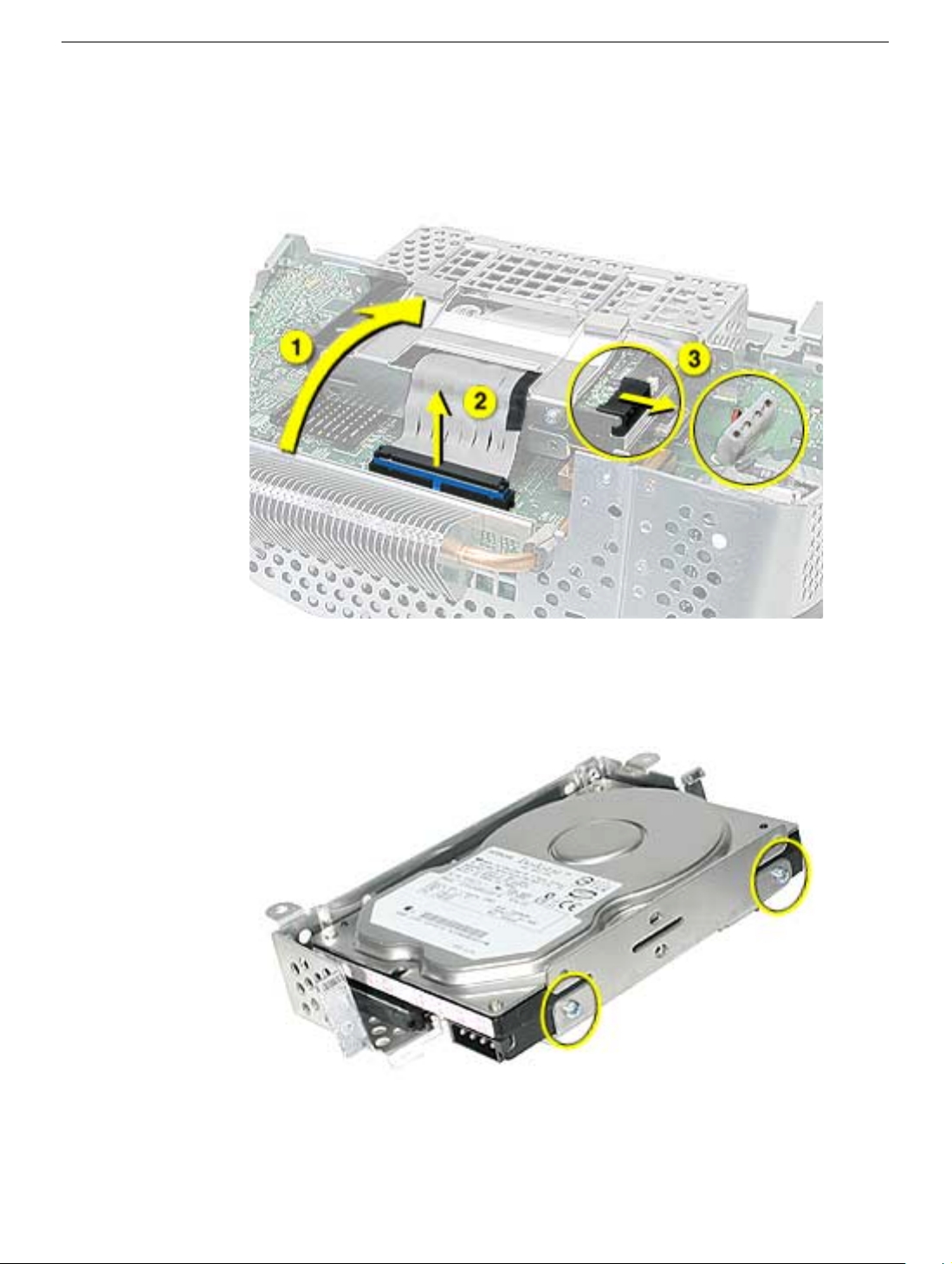
3. With the drive carrier flipped over (#1), disconnect the data cable (#2) and the power
cable (#3) from the hard drive.
4. To remove the hard drive from the carrier, remove two screws on the side of the
carrier.
Hard Drive
eMac (ATI Graphics) Take Apart - 35
Page 39

5. Tilt the drive to access the cable. Disconnect the cable from the hard drive. Note: If
you are replacing the drive carrier, review the procedure “Thermal Pad and EMI
Replacement” below.
Thermal Pad and EMI Replacement
1. If you are replacing the hard drive carrier, attach the thermal pad, and two rubber
bumpers to the top side of the carrier. Note: These pieces come with the replacement
carrier. Then, go on to the next step.
36 eMac (ATI Graphics) Take Apart
Hard Drive
Page 40

2. Attach two the EMI pads to the bottom side of the carrier.
Hard Drive
eMac (ATI Graphics) Take Apart - 37
Page 41

Logic Board Heatsink
Tools
This procedure requires the following tools:
• Screwdriver to pry the heatsink clip
Part Location
Preliminary Steps
Before you begin, do the following:
• Place the computer face down on an ESD mat.
• Remove the user access door.
• Remove the feet.
• Remove the rear housing.
• Discharge the CRT.
• Remove the fan.
• Remove the Faraday plate.
• Remove the digital assembly.
• Remove the hard drive carrier.
38 eMac (ATI Graphics) Take Apart
Logic Board Heatsink
Page 42

Procedure
1. Remove the one screw attaching to the chassis (on the top left side). Next, with a
nylon probe tool (922-5065), push the heatsink clip through the hole in the logic board.
The clip will come loose on the top side of the logic board.
2. Unclip the other end of the heatsink clip on the top side of the logic board.
Logic Board Heatsink
eMac (ATI Graphics) Take Apart - 39
Page 43

3. Lift the heatsink from the logic board. Warning: The the CPU heatsink should have
minimum handling of the fins. Be very careful when handling this part.
Replacement Note: Whenever the heatsink is removed, the bottom side of the
heatsink and the top of the microprocessor must be cleaned and new thermal paste
must be applied to the microprocessor. If the mating surfaces are not cleaned and
thermal paste is not applied, the CPU may overheat and become damaged. Refer to
the next topic, “Thermal Paste Application”.
40 eMac (ATI Graphics) Take Apart
Logic Board Heatsink
Page 44

Thermal Paste Application
The microprocessor uses a heatsink/thermal pipe to transfer heat away. Whenever the
heatsink is removed, the bottom side of the heatsink and the top of the microprocessor
must be cleaned and thermal paste must be applied. If the mating surfaces are not
cleaned and thermal paste is not applied, the CPU may overheat and become damaged.
Tools
This procedure requires the following tools:
• Plastic stylus or nylon probe tool (922-5065) to remove the old thermal paste
• Thermal paste (922-4757), each tube contains 4-5 applications
Procedure
1. Thoroughly clean the thermal film from the heatsink surface with a plastic stylus or the
nylon probe tool. Do not use an abrasive material or liquid cleaner. Important: Be
extremely careful not to bend the fins on the heatsink.
Thermal Paste Application
eMac (ATI Graphics) Take Apart - 41
Page 45

2. Carefully remove the old thermal paste from the surface of the microprocessor. Gently
remove the paste with a plastic stylus or nylon probe tool.
3. Squeeze a drop of thermal paste onto the middle of the microprocessor as
shown.
42 eMac (ATI Graphics) Take Apart
Thermal Paste Application
Page 46

4. Spread the paste evenly over the processor. Important: On this product, it is critical
to spread the paste over the processor, or the chip could overheat.
5. Reinstall the heatsink and the heatsink clip.
Thermal Paste Application
eMac (ATI Graphics) Take Apart - 43
Page 47

Logic Board
Tools
This procedure requires the following tools:
• Phillips #2 screwdriver
Part Location
Preliminary Steps
Before you begin, do the following:
• Place the computer face down on an ESD mat.
• Remove the user access door.
• Remove the feet.
• Remove the rear housing.
• Discharge the CRT.
• Remove the fan.
• Remove the Faraday plate.
44 eMac (ATI Graphics) Take Apart
Logic Board
Page 48

• Remove the digital assembly.
• Remove the hard drive carrier
• Remove the AirPort Extreme Card (if present)
Logic Board
eMac (ATI Graphics) Take Apart - 45
Page 49

Procedure
1. Disconnect the optical data cable, the optical power cable and release the heatsink
clip.
2. Remove the down converter screw that attaches to the chassis frame.
46 eMac (ATI Graphics) Take Apart
Logic Board
Page 50

3. On the left side, disconnect the power button cable and the modem cable.
4. Turn the assembly so the logic board is facing up. Remove the heatsink.
Logic Board
eMac (ATI Graphics) Take Apart - 47
Page 51

5. Remove the four screws on the logic board.
6. To remove the logic board from the chassis frame, unhook the chassis clips under the
I/O panel and on the top right side of the chassis frame.
48 eMac (ATI Graphics) Take Apart
Logic Board
Page 52

7. Hold the board by the down converter (#1) and gently pull the chassis frame (#2) on
the bottom right corner away from the board. Remove the logic board (#3) out of the
chassis frame. Carefully maneuver the board out of the frame.
Important: The microprocessor uses a heatsink/thermal pipe to transfer heat away.
Whenever the heatsink is removed, the bottom side of the heatsink and the top of the
microprocessor must be cleaned and thermal paste must be applied to the
microprocessor. If the mating surfaces are not cleaned and thermal paste is not
applied, the CPU may overheat and become damaged. Refer to “Thermal Paste
Application” in this chapter.
Logic Board
Replacement Note: Before returning the logic board to Apple, remove the following items:
• I/O panel frame
• RJ-11 connector (if present)
• Modem board
• Memory
• Heatsink
• Down converter
• AirPort Extreme Card (if present)
eMac (ATI Graphics) Take Apart - 49
Page 53

Down Converter
Tools
This procedure requires the following tools:
• Phillips #2
Part Location
Preliminary Steps
Before you begin, do the following:
• Place the computer face down on an ESD mat.
• Remove the user access door.
• Remove the feet.
• Remove the rear housing.
• Discharge the CRT.
• Remove the fan.
• Remove the Faraday plate.
• Remove the digital assembly.
50 eMac (ATI Graphics) Take Apart
Down Converter
Page 54

Procedure
1. Remove the screw attaching the down converter to the chassis frame.
2. Turn the logic board right side up. Hold the board by the down converter (#1) and
gently pull the chassis frame (#2) on the bottom right corner away from the board.
Remove the logic board (#3) out of the chassis frame. Carefully maneuver the board
out of the frame.
Down Converter
eMac (ATI Graphics) Take Apart - 51
Page 55

3. Now you can access the down converter board
4. Turn the logic board over so you can see the logic board-to-down converter connector.
Pull the down converter in the direction of the arrow to disconnect it from the logic
board.
52 eMac (ATI Graphics) Take Apart
Down Converter
Page 56

5. Slide the down converter off the logic board in the direction of the arrow.
Replacement Note: Note how the cables are routed for reassembly.
Down Converter
eMac (ATI Graphics) Take Apart - 53
Page 57

I/O Panel
Tools
This procedure requires the following tools:
• Phillips #2 screwdriver
Part Location
Preliminary Steps
Before you begin, do the following:
• Place the computer face down on an ESD mat.
• Remove the user access door.
• Remove the feet.
• Remove the rear housing.
• Discharge the CRT.
• Remove the fan.
• Remove the Faraday plate.
54 eMac (ATI Graphics) Take Apart
I/O Panel
Page 58

• Remove the digital assembly.
• Remove the logic board.
I/O Panel
eMac (ATI Graphics) Take Apart - 55
Page 59

Procedure
1. Remove the logic board from the chassis frame to access the I/O panel.
2. Remove the two I/O panel screws.
56 eMac (ATI Graphics) Take Apart
I/O Panel
Page 60

3. First, pull the I/O panel away from the ports (#1) on the logic board. Next, carefully pull
the I/O fence away from the connectors on the end of the board (#2).
I/O Panel
eMac (ATI Graphics) Take Apart - 57
Page 61

RJ-11 Cable
Tools
• Nylon probe tool (922-5065)
Part Location
Preliminary Steps
Before you begin, do the following:
• Place the computer face down on an ESD mat.
• Remove the user access door.
• Remove the feet.
• Remove the rear housing.
• Discharge the CRT.
• Remove the fan.
• Remove the Faraday plate.
• Remove the digital assembly.
• Remove the logic board
• Remove the I/O panel
58 eMac (ATI Graphics) Take Apart
RJ-11 Cable
Page 62

Procedure
1. Disconnect the RJ-11 cable from the modem.
2. Turn over the logic board. There is a small pry slot on the board for a screwdriver blade
to get behind the connector. See the next step.
RJ-11 Cable
eMac (ATI Graphics) Take Apart - 59
Page 63

3. Carefully push the RJ-11 port connector off the logic board with a nylon probe tool or
screwdriver.
60 eMac (ATI Graphics) Take Apart
RJ-11 Cable
Page 64

AirPort Extreme Card
Tools
This procedure requires the following tools:
• Phillips #2
Part Location
Preliminary Steps
Before you begin, do the following:
• Place the computer so that the front of the computer faces you.
AirPort Extreme Card
eMac (ATI Graphics) Take Apart - 61
Page 65

Procedure
1. Press the optical door in on one side and pull the door open on the other side to
access the AirPort access panel.
62 eMac (ATI Graphics) Take Apart
AirPort Extreme Card
Page 66

2. Loosen the two captive screws on the access panel. Remove the access panel.
3. Remove the access panel.
AirPort Extreme Card
eMac (ATI Graphics) Take Apart - 63
Page 67

4. Untuck the clear tab attached to the AirPort Extreme Card.
5. Pull the AirPort Extreme Card out of the slot a little bit to access the antenna
connected to the card.
64 eMac (ATI Graphics) Take Apart
AirPort Extreme Card
Page 68

6. Disconnect the antenna cable from the AirPort Extreme card.
7. Pull the tab to remove the AirPort Extreme card from the slot.
AirPort Extreme Card
eMac (ATI Graphics) Take Apart - 65
Page 69

LED
Tools
This procedure requires the following tools:
• Phillips #2
Part Location
Preliminary Steps
Before you begin, do the following:
• Place the computer face down on an ESD mat.
• Remove the user access door.
• Remove the feet.
• Remove the rear housing.
• Discharge the CRT.
66 eMac (ATI Graphics) Take Apart
LED
Page 70

• Remove the fan.
• Remove the Faraday plate.
LED
eMac (ATI Graphics) Take Apart - 67
Page 71

Procedure
1. Remove one screw and disconnect the LED cable. Important: The connector is very
fragile, remove it gently. Lift the LED board off the front bezel.
68 eMac (ATI Graphics) Take Apart
LED
Page 72

Front Bezel
Tools
This procedure requires the following tools:
• Phillips #2
Part Location
Front Bezel
Preliminary Steps
Before you begin, do the following:
• Place the computer face down on an ESD mat.
• Remove the user access door.
• Remove the feet.
• Remove the rear housing.
• Discharge the CRT.
• Remove the fan.
eMac (ATI Graphics) Take Apart - 69
Page 73

• Remove the Faraday plate.
• Remove the digital assembly
• Remove the display/analog assembly
70 eMac (ATI Graphics) Take Apart
Front Bezel
Page 74

Procedure
1. Remove the eight bezel screws. There are three on each side and two at the top of the
bezel.
Important: DO NOT remove the two larger screws circled below, or the two screws
shown in the next photo. If they are removed, the CRT will be out of alignment and
the entire display/analog assembly will need to be replaced.
2. Note: DO NOT remove the CRT screws (circled) near the speakers either.
3. Carefully lift the display/analog assembly off the bezel.
Front Bezel
eMac (ATI Graphics) Take Apart - 71
Page 75

4. Remove the microphone, speakers, and LED from the bezel.
5. Note: Remove the antenna board from the display/analog assembly before returning
the display/analog assembly to Apple. Refer to the next procedure, “Antenna Board”
for details.
72 eMac (ATI Graphics) Take Apart
Front Bezel
Page 76
Antenna Board
Tools
This procedure requires the following tools:
• Phillips #2 screwdriver
• Needlenose pliers or flat blade screwdriver
Part Location
Antenna Board
Preliminary Steps
Before you begin, do the following:
• Remove the AirPort Extreme card
• Place the computer face down on an ESD mat.
• Remove the user access door.
• Remove the feet.
• Remove the rear housing.
• Discharge the CRT.
• Remove the fan.
eMac (ATI Graphics) Take Apart - 73
Page 77

• Remove the Faraday plate.
• Remove the digital assembly.
• Remove the digital/analog assembly.
74 eMac (ATI Graphics) Take Apart
Antenna Board
Page 78

Procedure
1. Remove one screw on the antenna board.
Next, peel back the masking tape and pull the unused end of the antenna through the
hole in the digital/analog chassis.
2. Carefully position the computer so that the CRT faces you.
Locate the metal antenna bracket at the top of the CRT. Remove the screw on the
bracket, then pry the antenna cable from the two clips on the side of the CRT.
Antenna Board
eMac (ATI Graphics) Take Apart - 75
Page 79

Microphone
Tools
This procedure requires the following tools:
• Phillips #2
Part Location
Preliminary Steps
Before you begin, do the following:
• Place the computer face down on an ESD mat.
• Remove the user access door.
• Remove the feet.
• Remove the rear housing.
• Discharge the CRT.
• Remove the fan.
76 eMac (ATI Graphics) Take Apart
Microphone
Page 80

• Remove the Faraday plate.
• Remove the digital assembly.
• Remove the display/analog assembly.
Procedure
1. Carefully lift the display/analog assembly from the bezel to access the microphone.
2. Remove the microphone cable from the bezel.
Microphone
eMac (ATI Graphics) Take Apart - 77
Page 81

Door Assembly
Tools
This procedure requires the following tools:
• Phillips #2
Part Location
Preliminary Steps
Before you begin, do the following:
• Place the computer face down on an ESD mat.
• Remove the user access door.
• Remove the feet.
• Remove the rear housing.
• Discharge the CRT.
• Remove the fan.
78 eMac (ATI Graphics) Take Apart
Door Assembly
Page 82

• Remove the Faraday plate.
• Remove the digital assembly.
Procedure
1. Remove the two screws connecting the door to the front bezel. Remove the door from
the front bezel.
2. Replacement Note: Transfer the serial number label on the inside of the door to the
replacement door.
Door Assembly
eMac (ATI Graphics) Take Apart - 79
Page 83

Memory
Tools
• No tools are required for this procedure
Part Location
Preliminary Steps
Before you begin, do the following:
• Place the computer face down on an ESD mat.
• Unplug all cables except the power cord, from the computer.
• Remove the user access door.
80 eMac (ATI Graphics) Take Apart
Memory
Page 84

Procedure
1. Touch a metal surface inside the computer. Then unplug the computer.
Important: Always ground yourself before you touch any parts, or remove/install any
components inside the computer. To avoid generating static electricity, do not walk
around until you have finished removing or installing the memory and closed the
computer.
Memory
eMac (ATI Graphics) Take Apart - 81
Page 85

2. Push the ejectors on the memory slot outward and down so they are in the open
position. Remove the memory module. Replacement Note: The memory is designed
to fit into the slot only one way. Be sure to align the notches on the module with the
small notches inside the slot.
82 eMac (ATI Graphics) Take Apart
Memory
Page 86
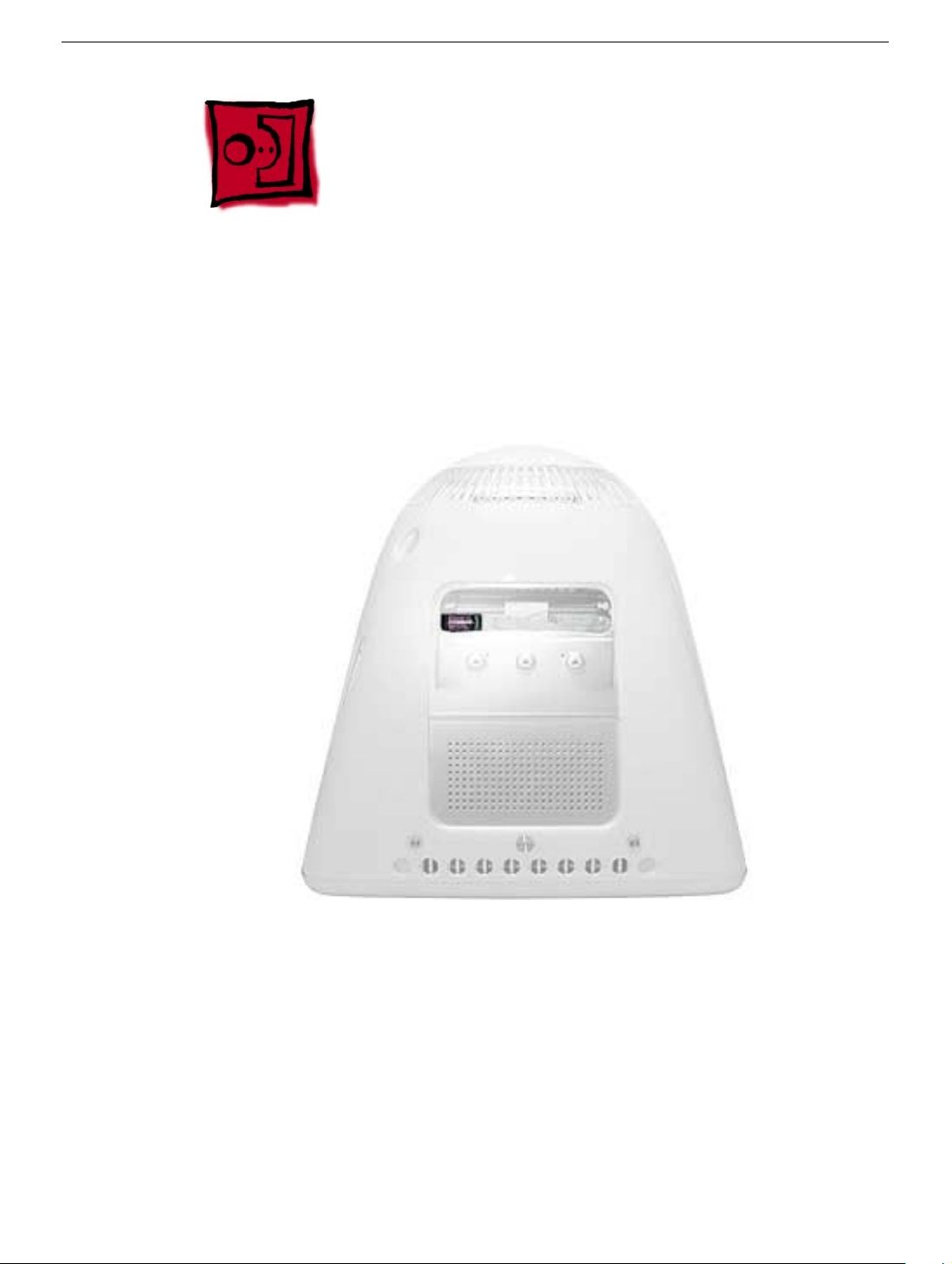
Battery
Tools
• No tools are required for this procedure
Part Location
Note: The battery can be accessed through the user access door on the back of the
computer.
Battery
Preliminary Steps
Before you begin, do the following:
• Place the computer face down on an ESD mat.
• Unplug all cables except the power cord, from the computer.
• Remove the user access door.
eMac (ATI Graphics) Take Apart - 83
Page 87

Procedure
1. Touch a metal surface inside the computer. Then unplug the computer. Important:
Always do this before you touch any parts, or remove/install any components inside
the computer. To avoid generating static electricity, do not walk around until you have
finished removing or installing the battery and closed the computer.
2. WIth the nylon probe tool, carefully pry the battery out of the battery holder.
84 eMac (ATI Graphics) Take Apart
Battery
Page 88

Modem
Tools
This procedure requires the following tools:
• Phillips #1 or jeweler’s screwdriver
Part Location
Modem
Preliminary Steps
Before you begin, do the following:
• Place the computer face down on an ESD mat.
• Remove the user access door.
• Remove the feet.
• Remove the rear housing.
• Discharge the CRT.
• Remove the fan.
• Remove the Faraday plate.
eMac (ATI Graphics) Take Apart - 85
Page 89

Procedure
1. Remove the two modem screws and disconnect the RJ-11 cable from the modem.
2. Lift the modem from the connector on the logic board.
86 eMac (ATI Graphics) Take Apart
Modem
Page 90

Display/Analog Assembly
Tools
This procedure requires the following tools:
• No tools are required
Warning: This product contains high voltage and a high-vacuum picture tube. To prevent
injury, always review CRT Safety on Service Source online. This link can be found under
the list of topics under the iMac icon. Remember, never use a grounding wriststrap until
after discharging the CRT and setting up an ongoing ground connection.
Note: The eMac (ATI Graphics) display/analog assembly requires no voltage calibration or
geometry adjustment. Should the display require adjustment (focus, color, or brightness)
use the “Displays” pane under System Preferences if using Mac OS X. If using Mac OS 9,
use the Monitor Control Panel to make adjustments. If you can not make satisfactory
corrections with these tools, replace the display/analog assembly.
Part Location
Display/Analog Assembly
eMac (ATI Graphics) Take Apart - 87
Page 91

Preliminary Steps
Before you begin, do the following:
• Place the computer face down on an ESD mat
• Remove the user access door
• Remove the feet
• Remove the rear housing
• Discharge the CRT.
• Remove the fan
• Remove the Faraday plate
• Remove the digital assembly
• Remove the AirPort Extreme Card
• Remove the front bezel
• Remove the antenna.
If you remove everything listed in the steps above, you are left with the display/analog
module. There is nothing more to remove from this module.
Note: The display/analog assembly contains a non-switching power supply which is preset
at a 220V configuration.The voltage selection needs to be manually set by the way of a
voltage jumper. This means if you are operating the computer in a 110V environment, you
will have to install the voltage jumper. Refer to the Troubleshooting chapter, “Digital/
Analog”
Replacement Note: If you are returning a defective display/analog module, it is imperative
that proper packaging guidelines be followed. The packing procedure is included with the
replacement assembly. Incorrect packaging can result in damaged eMac (ATI Graphics)
displays. Please read and follow the directions enclosed in the shipping box of the new
display prior to packaging the defective module.
Failure to package the defective module according to the instructions may result in liability
for the cost of the damaged display.
88 eMac (ATI Graphics) Take Apart
Display/Analog Assembly
Page 92

LHR Coil
Tools
This procedure requires the following tools:
• Phillips #2 AirPort Extreme Card screwdriver
Part Location
Note: This part is used in Europe for line conditioning. If your computer does not have the
LHR coil, skip this procedure.
LHR Coil
Preliminary Steps
Before you begin, do the following:
• Place the computer face down on an ESD mat.
• Remove the user access door.
• Remove the feet.
• Remove the rear housing.
• Discharge the CRT.
eMac (ATI Graphics) Take Apart - 89
Page 93

Procedure
1. Remove the screw located at the top of the LHR coil.
2. Disconnect the LHR connector located next to the fuse.
3. Lift the LHR coil from the display/analog frame.
90 eMac (ATI Graphics) Take Apart
LHR Coil
Page 94

LHR Coil
eMac (ATI Graphics) Take Apart - 91
Page 95

Service Source
Troubleshooting
eMac (ATI Graphics)
© 2003 Apple Computer, Inc. All rights reserved.
Page 96

General Information
What’s New
1. To quickly identify the eMac (ATI Graphics) computer from t he original eMac, look at the user access
door on the back of the computer. The user access door on the eMac (ATI Graphics) computer is white.
The original eMac has a silver user access door.
2. There are two new logic boards with faster processors: 661-2854 (1GHZ) and 661-2853 (800 MHz).
3. The eMac (ATI Graphics) uses the AirPort Extreme Card for wireless networking. The original AirPort
card can not be used in this computer. Previous models of eMac used the original AirPort card. For
compatibility information, see AppleCare Knowledge Base article 107440: AirPort Extreme Card:
Compatible Macintosh Computers.
4. Note: The AirPort Extreme Card can not be used under Mac OS 9.
5. The
6. The digital module assembly has been redesigned allowing easier removal and access to the optical
7. The heatsink has been redesigned.
8. The voltage jumper and LHR jumper are in new locations on the digital/analog assembly. Refer to
9. The hard drive carrier has one thermal pad and two rubber bumpers on the top side of the carrier. On the
10. The power button of the eMac (ATI Graphics) replaces the power reset button and programmer's switch
PMU reset button is in a new location. Refer to the topic, “The PMU Chip” or “Resetting
the PMU on the Logic Board” in this chapter.
drive without removing the digital module.
“Display/Analog Voltage Setting and LHR Module Instructions” in this chapter for more information.
underside of the carrier there are two EMI pads. If you replace the carrier, these pieces come with the
replacement carrier and need to be attached before inserting the hard drive.
(NMI button, also known as a NMI or nonmaskable interrupt button). You can use the power button for the
following functions:
Sleep
Press the power button for 1 second to put the computer to sleep. To wake the computer from
sleep, press the power button for less than one second or press any key on the keyboard.
Shut down
To shut down the computer, select Shut Down from the Apple menu (Mac OS X) or from the
Special menu (Mac OS 9). You will be prompted to save any unsaved documents.
If the computer is unresponsive, you can force the computer to shut down by pressing the
power button and holding it for at least 5 seconds. Important: Information in any unsaved
documents may be lost.
General Information
eMac (ATI Graphics) Troubleshooting - 1
Page 97

Firmware updates
From time to time, Apple has provided firmware updates to address certain issues that
cannot be addressed in updates to software. On earlier computers, the programmer's switch
was used to install a firmware update.
Follow these steps in the event that a firmware update is needed for these computers:
1. Shut down the computer.
2. Wait until the computer is shut down and the power button light is off.
3. Press and hold the power button for several seconds.
4. The computer will signal that a firmware update is ready to be installed by a making a
steady tone and the power button light will quickly flash several times for several seconds.
What’s Important
1. Important: The display/analog (service module) contains a non-switching power supply which is
preset at a 220V configuration. The voltage selection is manually set by way of a voltage jumper. This
means if you are replacing the display/analog assembly and you will be operating the computer in a
110V environment, you will have to install the voltage jumper on the replacement module. Refer to the
inbox instruction included with the display/analog service module, or refer to “Display/Analog Voltage
Setting and LHR Module Instructions” discussed later in this chapter.
Note: The LHR coil (line conditioning module) is used in some international countries. Refer to the
Take Apart chapter, LHR topic, for take-apart information.
2. Important: If you are returning a defective display/analog assembly, it is imperative that proper
packaging guidelines be followed. The packing procedure is included with the replacement assembly.
Incorrect packaging can result in damaged eMac displays. Please read and follow the directions
enclosed in the shipping box of the new display prior to packaging the defective module.Failure to
package the defective module according to the instructions may result in liability for the cost of the
damaged display.
3. Important: Do NOT lift, handle, bump, or manipulate the CRT neck/neck board on the Display/Analog
assembly. Modules damaged by mishandling are NOT covered by Apple Warranty. Apple Authorized
Service Providers can be liable for broken CRT necks due to improper handling. Refer to “CRT Neck/
Display/Analog Assembly Handling Information” topic in this chapter for more information.
4. The eMac (ATI Graphics) display/analog assembly requires no voltage calibration or geometry
adjustment. Should the display appear to require adjustment (focus, color, or brightness) use the
“Displays” pane under System Preferences if using Mac OS X. If using Mac OS 9, use the Monitor
Control Panel. If you can not make satisfactory corrections with these tools, replace the display/analog
assembly.
5. Important: The microprocessor uses a heatsink/thermal pipe to transfer heat away. Whenever the
heatsink is removed, the bottom side of the heatsink and the top of the microprocessor must be
cleaned and thermal paste must be applied to the microprocessor. If the mating surfaces are not
cleaned and thermal paste is not applied, the CPU may overheat and become damaged. Refer to
“Thermal Paste Application” in this chapter.
2 - eMac (ATI Graphics) Troubleshooting
General Information
Page 98

Logic Board, Top Side
Sound Output Port
Microphone
Connector
Fan Power
Connector
LED
Connector
Speaker
Connector
Sound Input Port
USB Ports
FireWire Ports
RJ-11 (Modem Not Shown)
Ethernet Port
Video Output Port
Power Button
Connector
Video
Connector
Battery
Optical
Connector
SDRAM
Memory
Slots
PMU
General Information
eMac (ATI Graphics) Troubleshooting - 3
Page 99

Logic Board, Bottom Side
Video
Processor
Hard
Drive
Connector
AirPort
Extreme
Connector
Blind Mate
Connector
G4
Microprocessor
4 - eMac (ATI Graphics) Troubleshooting
General Information
Page 100

I/O Ports
The ports listed from left to right are:
• Headphone
• Sound out port
• USB ports (3)
• FireWire ports (2)
• Modem
• Ethernet
• Video out port
General Information
eMac (ATI Graphics) Troubleshooting - 5
 Loading...