

Page 1
Service Source
eMac
© 2002 Apple Computer, Inc. All rights reserved.
Page 2

eMac
eMac -
1
Page 3
Service Source
Take Apart
eMac
© 2002 Apple Computer, Inc. All rights reserved.
Page 4

Tools
The following tools are recommended for the take apart procedures.
• 2.5 mm hex (for rear housing)
• phillips #2 screwdriver
• jeweler’s screwdriver set
• needlenose pliers
• ESD wriststrap and mat
• CRT discharge tool
Note:
Do not use a power driver on the rear housing screws.
Tools
eMac Take Apart -
1
Page 5

CRT Neck/Display/Analog Assembly Handling Information
Handling
Important:
when working with the display/analog assembly.
Do NOT lift, handle, bump, or manipulate the CRT neck/neck board (see red arrows
below) on the Display/Analog assembly. Modules damaged by mishandling are NOT
covered by Apple Warranty. Apple Authorized Service Providers can be liable for broken
CRT necks due to improper handling.
Caution
handling the assembly. Lift the assembly from the metal chassis; never lift the assembly
from the neck. I
It is imperative that proper handling and packaging guidelines be followed
: The metal chassis has sharp edges, you may want to wear gloves when
2
eMac Take Apart
Packing a Defective Display/Analog Assembly
The packing procedure is included with the replacement display/analog assembly.
Incorrect packaging can result in damaged eMac displays. Please read and follow the
directions enclosed in the shipping box of the new display prior to packaging the defective
assembly. AASPs can be liable for broken CRT necks due to improper packing and
handling.
CRT Neck/Display/Analog Assembly Handling Infor-
Page 6
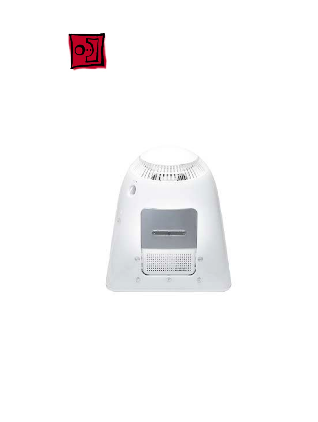
User Access Door
Tools
This procedure requires the following tools:
• Phillips #2 screwdriver
Part Location
User Access Door
Preliminary Steps
Before you begin, do the following:
• Place the computer face down on an ESD mat.
eMac Take Apart -
3
Page 7
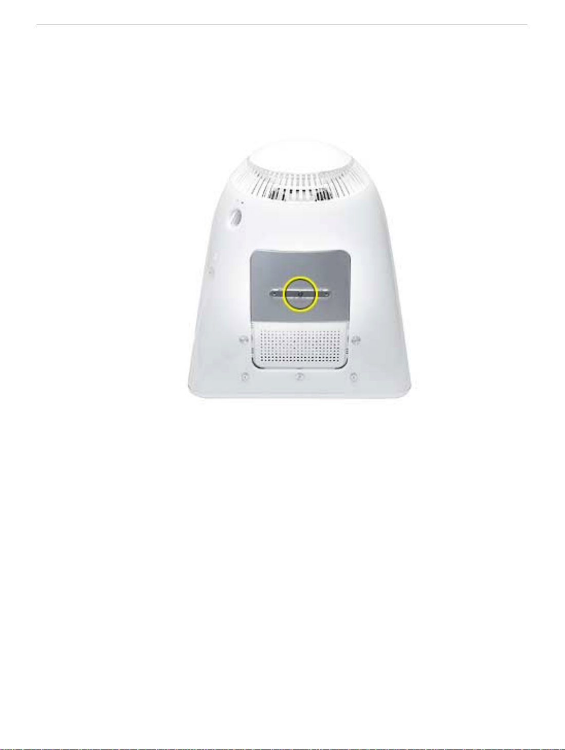
Procedure
1. Remove the screw on the user access door
2. Gently remove the access door.
4
eMac Take Apart
User Access Door
Page 8
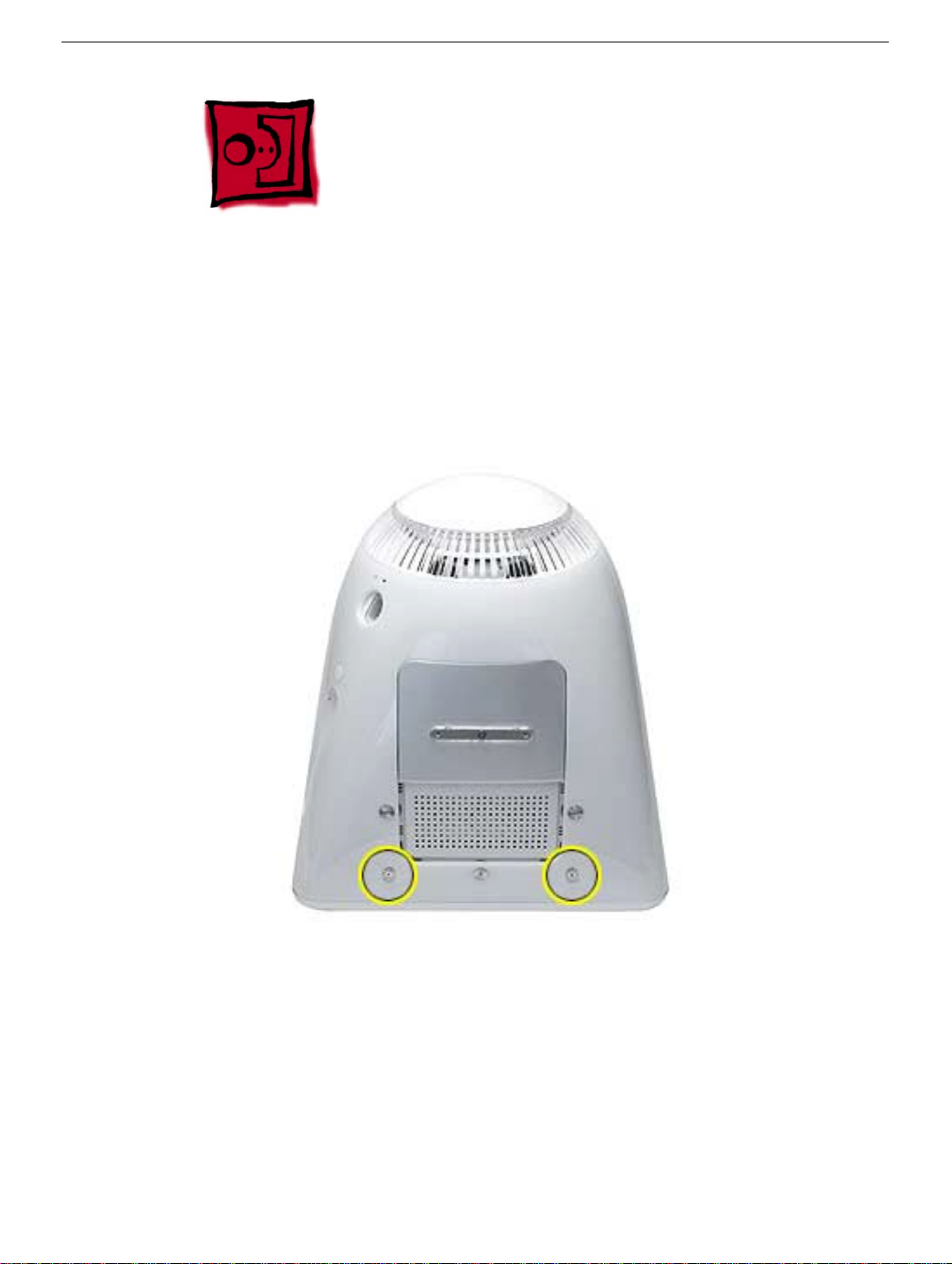
Feet
Tools
This procedure requires the following tools:
• Phillips #2 screwdriver
Part Location
Feet
Preliminary Steps
Before you begin, do the following:
• Place the computer face down on an ESD mat.
eMac Take Apart -
5
Page 9
Procedure
1. Remove the two screws. Set the plastic feet aside.
6
eMac Take Apart
Feet
Page 10
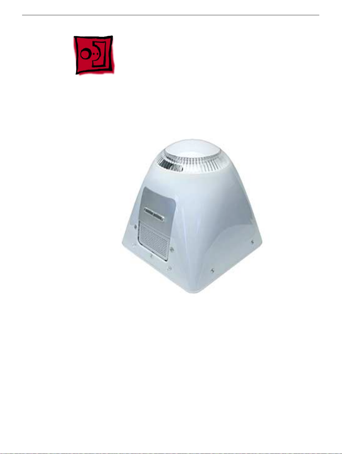
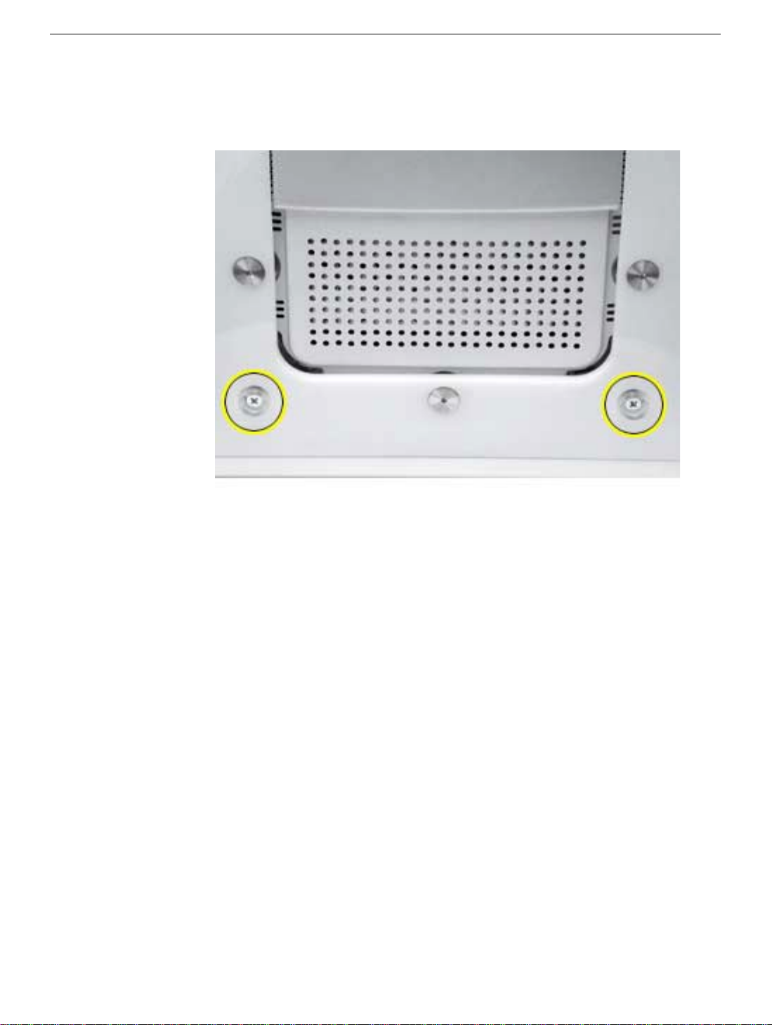
Rear Housing
Tools
• 2.5 mm hex.
Part Location
Rear Housing
Preliminary Steps
Before you begin, do the following:
• Place the computer face down on an ESD mat.
• Remove the feet.
eMac Take Apart -
7
Page 11
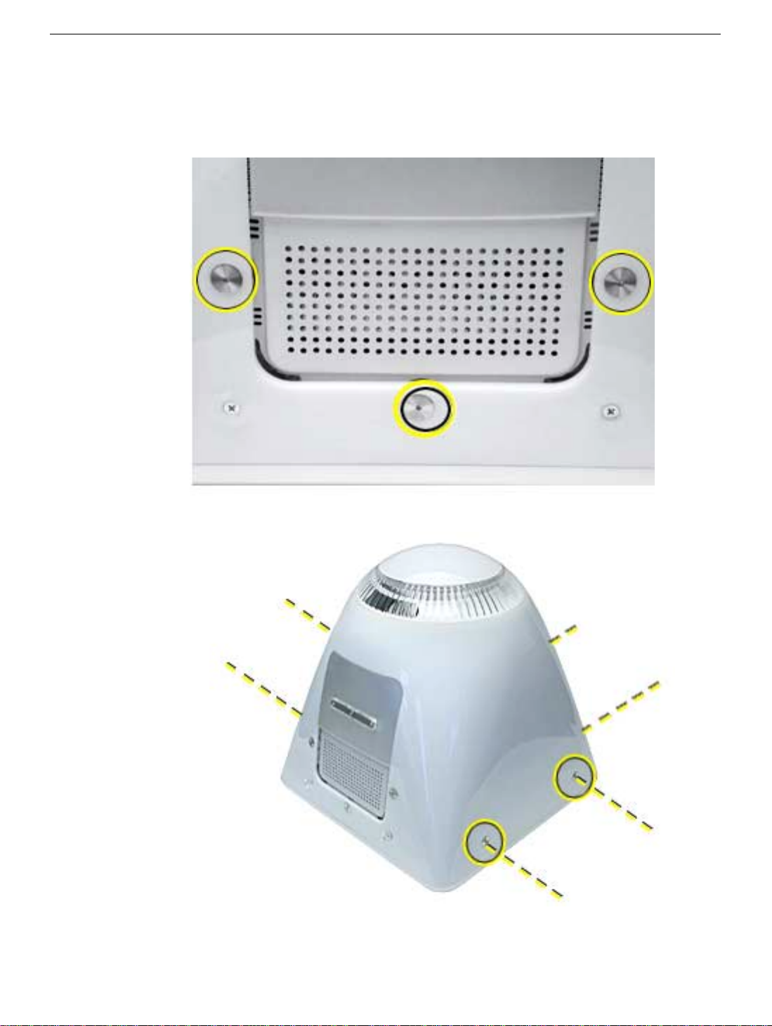
Procedure
1. Remove three screws located below the user access door (these three screws are
longer that the rest of the rear housing screws).
2. Remove the six remaining rear housing screws.
8
eMac Take Apart
Rear Housing
Page 12
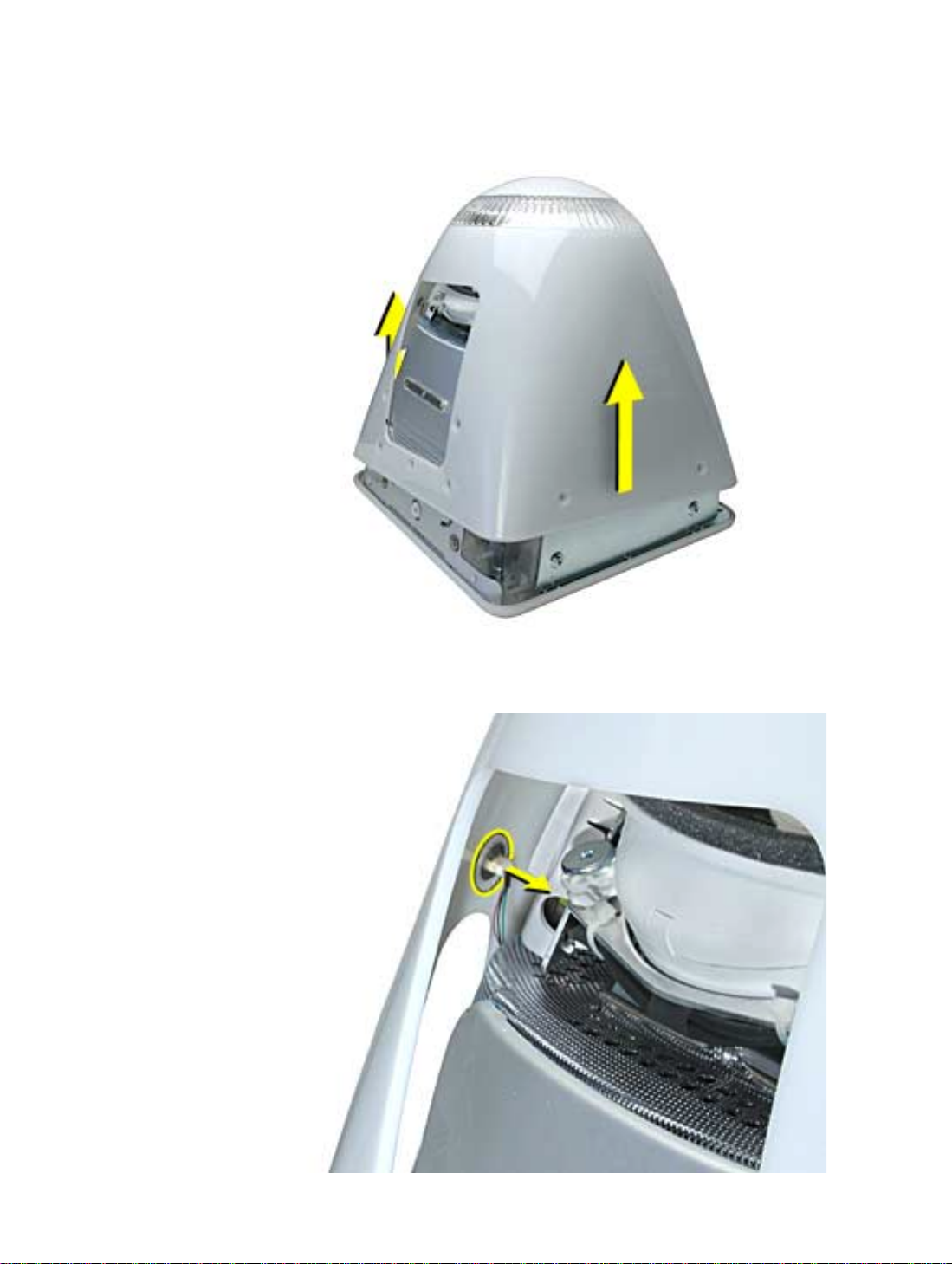
3. Gently lift the rear housing up about 2 inches.
the power button (on the inside of the housing) can become permanently damaged or
the machine may not power on.
Warning:
If you lift the housing too fast,
4. Carefully disconnect the power cable from the power button located inside the rear
housing. Lift the rear housing off the computer.
Rear Housing
eMac Take Apart -
9
Page 13
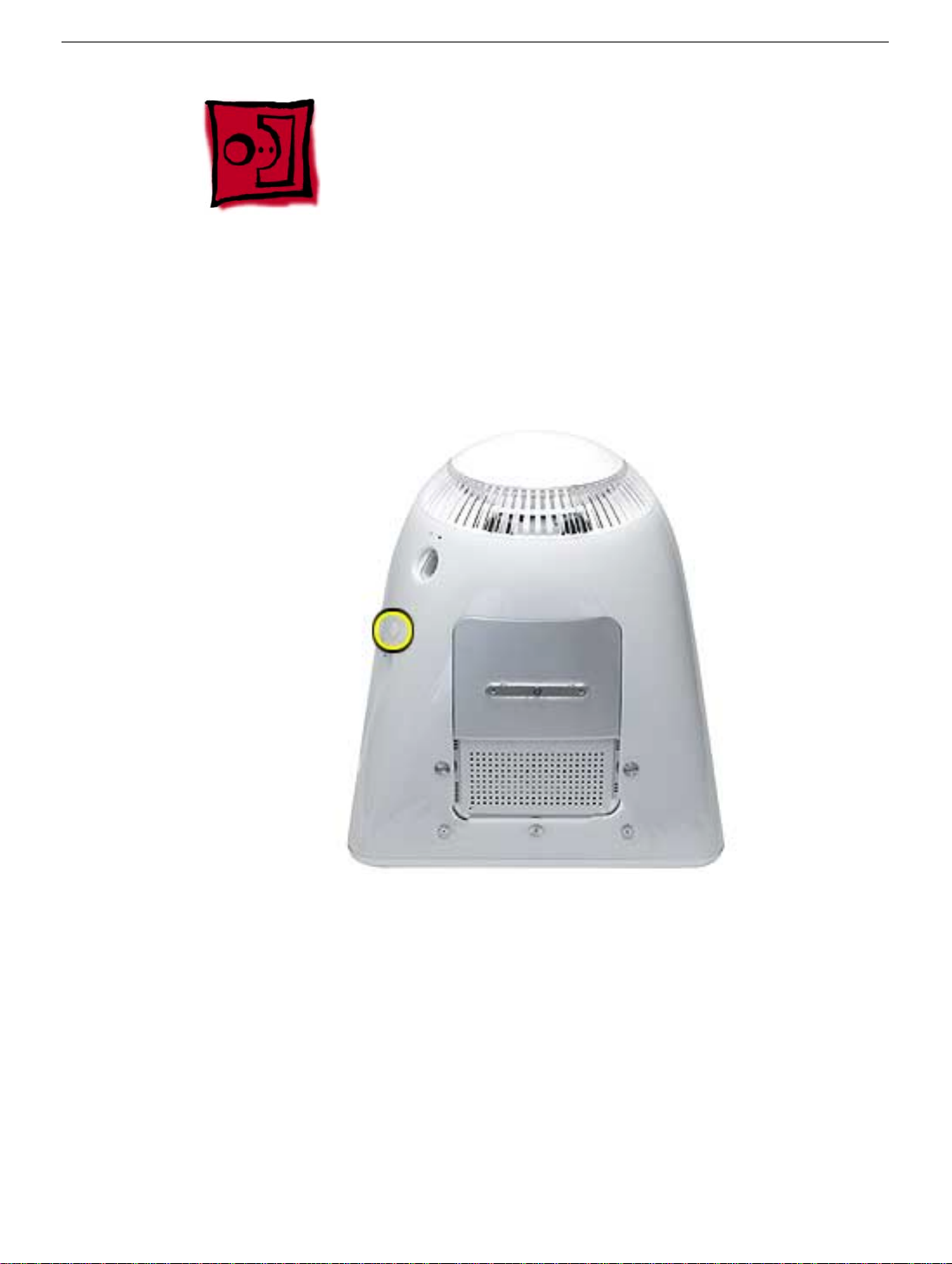
Power Button
Tools
• needlenose pliers
•
Note:
Follow this take-apart procedure only if you are replacing a defective power
button.
Part Location
10
eMac Take Apart
Preliminary Steps
Before you begin, do the following:
• Place the computer face down on an ESD mat.
• Remove the feet.
• Remove the rear housing.
Power Button
Page 14
Procedure
1. Disconnect the power cable from the power button located inside the rear housing. Lift
the rear housing off the computer.
2.
Note:
Continue with this procedure only if you are replacing a defective power button.
With a needlenose pliers, push the power button through the retaining ring. The power
button will pop off rear housing and the retaining ring may get stuck on the pliers.
Power Button
eMac Take Apart -
11
Page 15
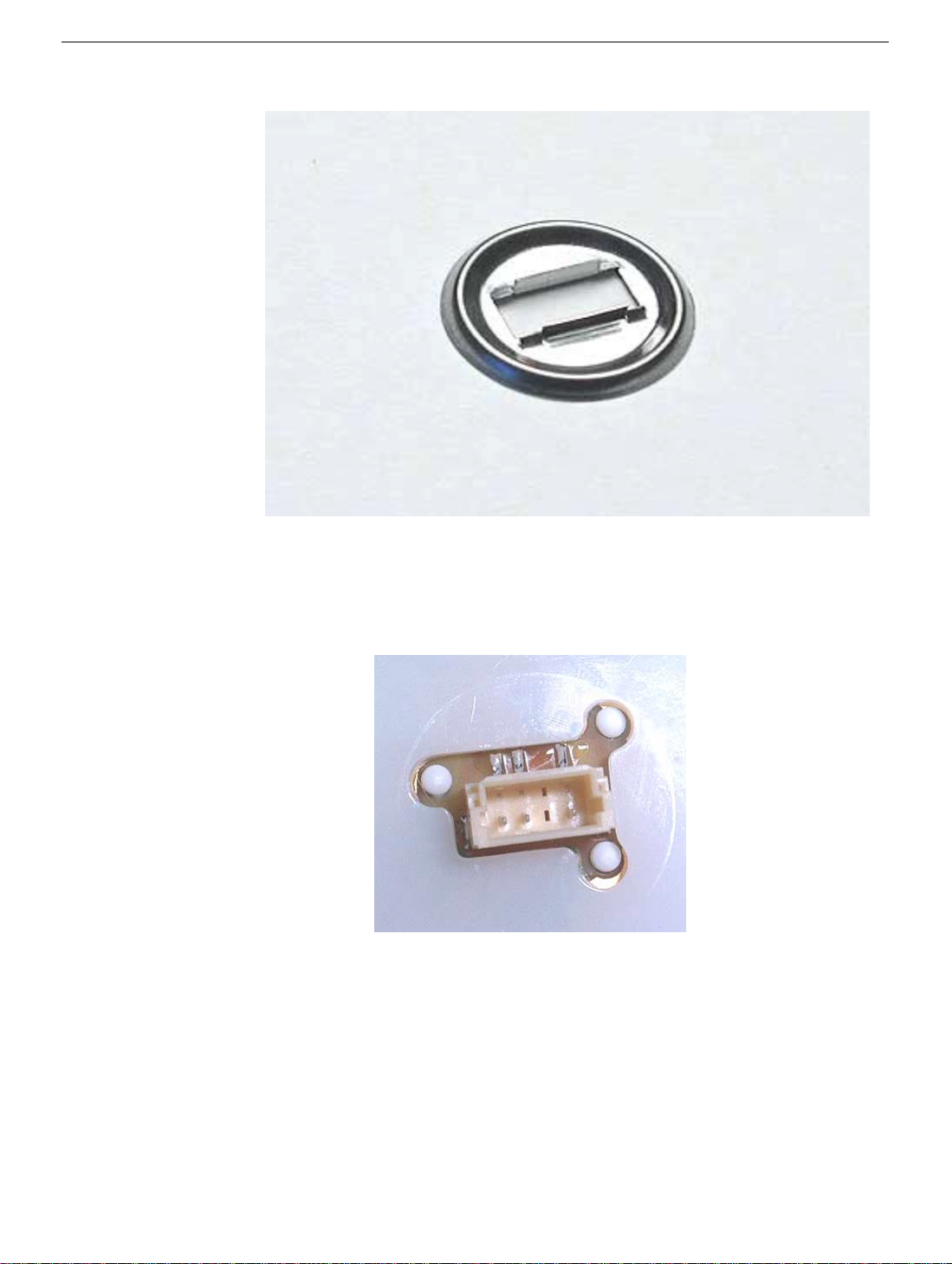
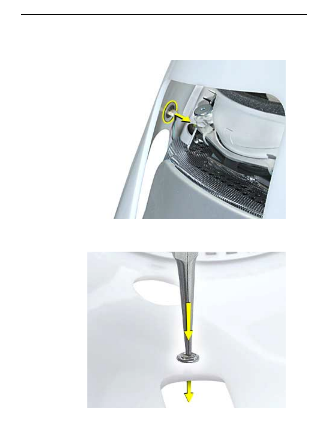
3. Save the retaining ring (shown below)
4.
Replacement Note:
power button. Position the power button into the hole on the rear housing (as shown
below).
rear housing.
Note:
The picture below is looking at the power button from the inside of the
Obtain a new power button and peel the sticky backing off the
12
eMac Take Apart
5. Place the retaining ring over the power button connector and press down firmly.
Power Button
Page 16
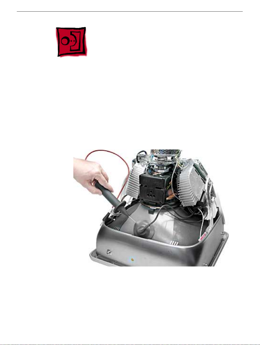
CRT Discharge
Warning:
injury, always review the Service Foundations: CRT Displays course for safety information.
It can be found at: http://service.info.apple.com/service_training/training.html. Click on
Desktop Certification Courses and select the Service Foundations: CRT Displays link.
Warning:
an ongoing ground connection.
This product contains high voltage and a high-vacuum picture tube. To prevent
Never use a grounding wriststrap until after discharging the CRT and setting up
Safety Guidelines:
Whenever the rear housing of the computer is removed and before replacing a module,
you must
1. Discharge the CRT (shown below) and remove the anode cap.
CRT Discharge
2. Establish an ongoing ground by using a cable with alligator clips at both ends.
Connect one end to the anode aperture, and connect the other end to the metal CRT
frame (as shown below).
3. With the CRT discharged and the ongoing ground in place wear a grounding
wriststrap to prevent equipment damage from static electricity.
eMac Take Apart -
13
Page 17
Speakers
Tools
This procedure requires the following tools:
• Jeweler’s #1 screwdriver (for removing metal plate on speaker assembly)
Part Location
14
eMac Take Apart
Preliminary Steps
Before you begin, do the following:
• Place the computer face down on an ESD mat.
• Remove the user access door.
• Remove the feet.
• Remove the rear housing.
• Discharge the CRT.
Speakers
Page 18
Procedure
1.
Note:
The speaker assembly is not screwed down. Gently pull the speaker assembly
in the direction of the arrow.
2. Disconnect the speaker cable on the left side. Lift the speaker assembly out of the
computer.
Speakers
eMac Take Apart -
15
Page 19
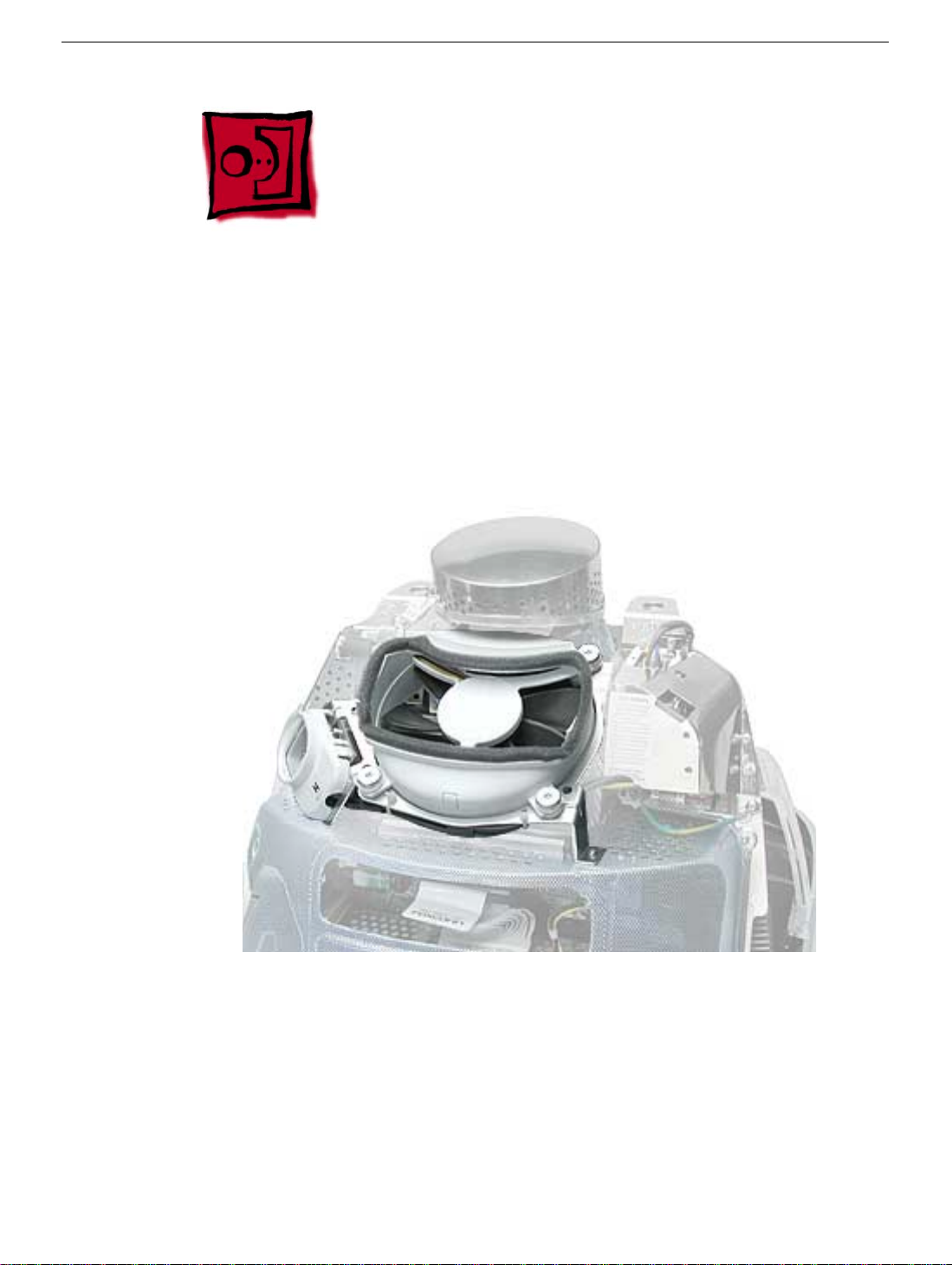
Fan
Tools
This procedure requires the following tools:
• Phillips #2
Part Location
16
eMac Take Apart
Preliminary Steps
Before you begin, do the following:
• Place the computer face down on an ESD mat.
• Remove the user access door.
• Remove the feet.
• Remove the rear housing.
• Discharge the CRT.
Fan
Page 20

Procedure
1. With the fan facing you, disconnect the two circled screws and disconnect the fan
cable.
2. On the right side of the fan, remove two screws (one of which is the ground screw),
and disconnect the fan power cable
.
Fan
eMac Take Apart -
17
Page 21
3. To locate the last fan screw, turn the computer so the anode socket is facing you. You’ll
see two screws. Remove the top screw.
4. To remove the fan, turn the computer so the fan is facing you. Grab onto the fan near
the AC plug and the bottom right corner of the fan. Gently pull the fan toward you and
away from the chassis. Be very careful of the CRT neck.
18
eMac Take Apart
Fan
Page 22
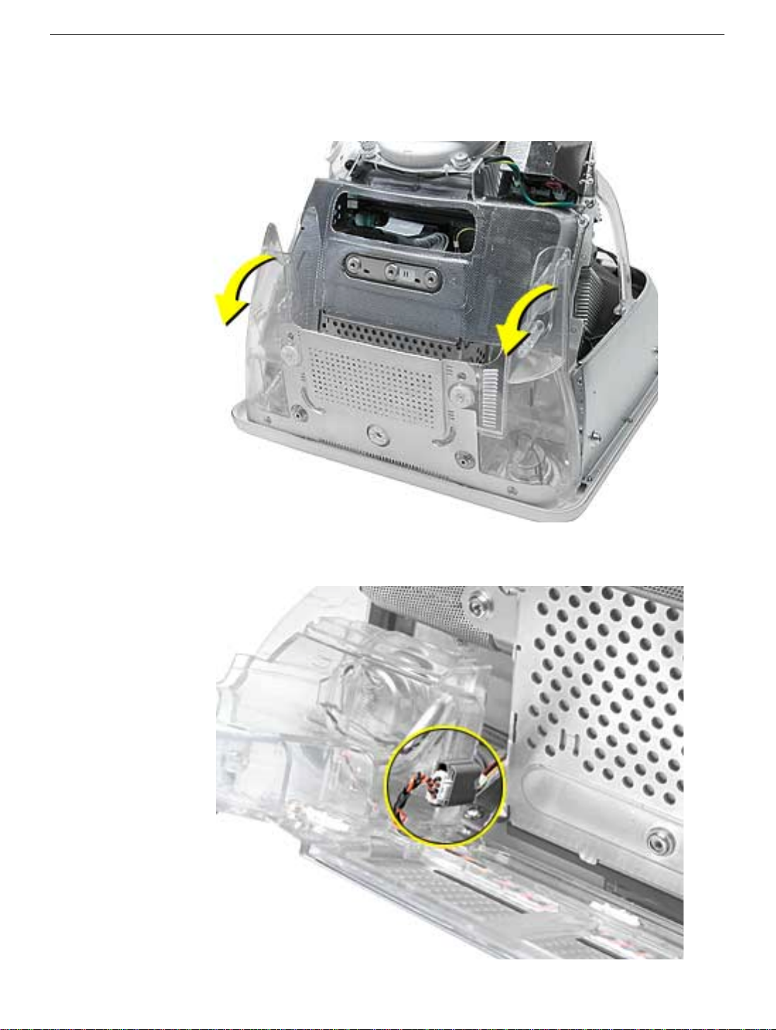
Faraday Cage
Tools
This procedure requires the following tools:
• Phillips #2
Part Location
Faraday Cage
Preliminary Steps
• Place the computer face down on an ESD mat.
• Remove the user access door.
• Remove the feet.
• Remove the rear housing.
• Discharge the CRT.
• Remove the fan.
eMac Take Apart -
19
Page 23
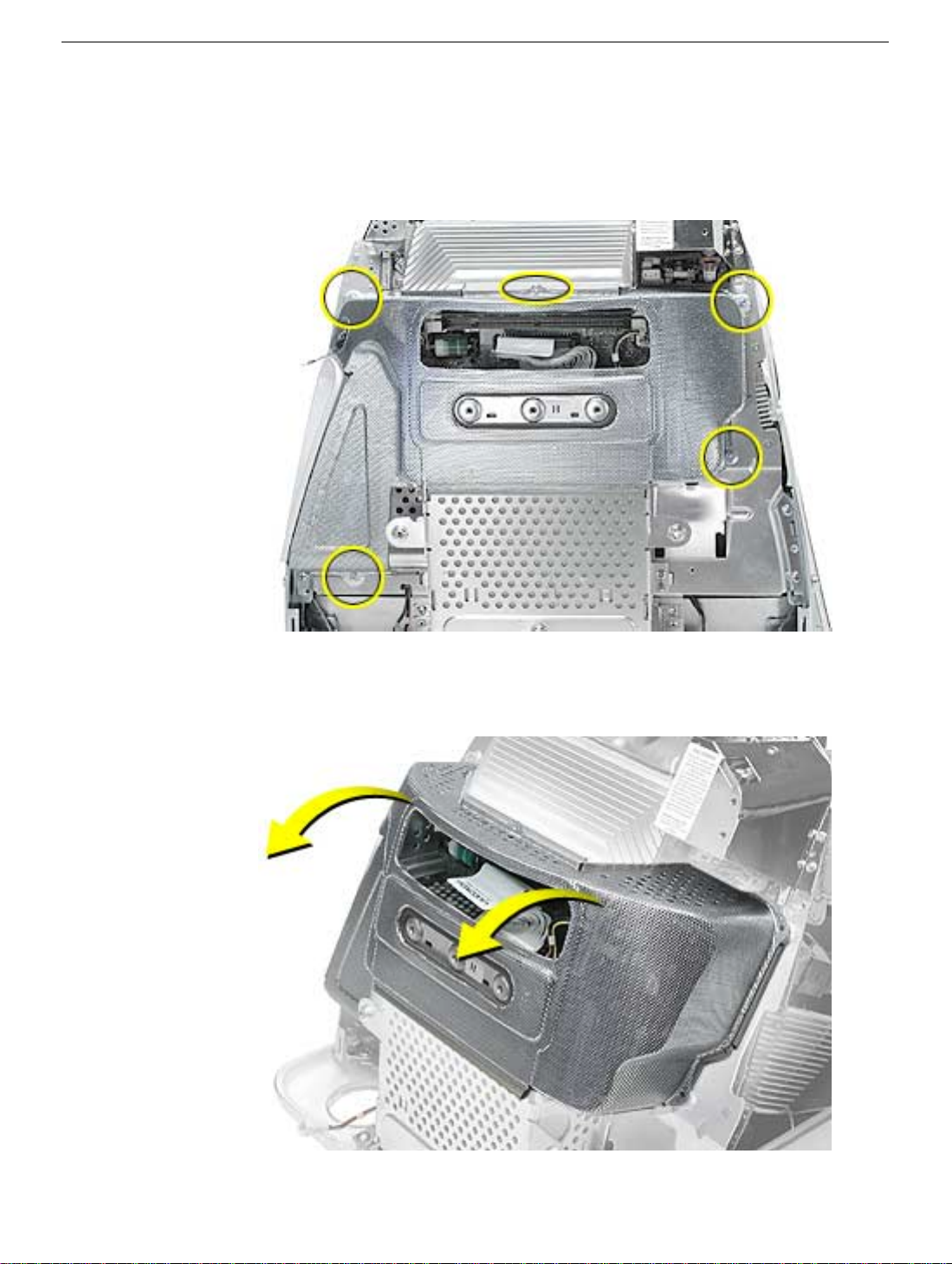
Procedure
1. Remove the five screws.
cage so it doesn’t get caught when you remove the Faraday cage.
Important:
Push the power button cable inside the Faraday
2. Gently pry the Faraday cage away from the chassis in the direction of the arrows.
20
eMac Take Apart
Faraday Cage
Page 24
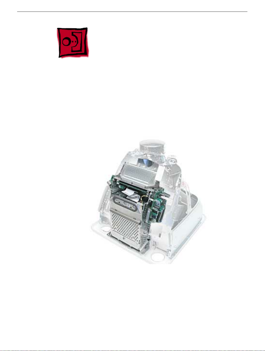
Digital Module Assembly
Tools
This procedure requires the following tools:
• Phillips #2
Part Location
Preliminary Steps
Before you begin, do the following:
• Place the computer face down on an ESD mat.
• Remove the user access door.
• Remove the feet.
• Remove the rear housing.
• Discharge the CRT.
Digital Module Assembly
eMac Take Apart -
21
Page 25

• Remove the fan.
• Remove the Faraday cage.
• Remove the AirPort Card if installed.
22
eMac Take Apart
Digital Module Assembly
Page 26
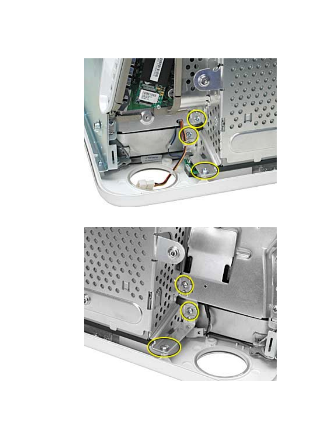
Procedure
1. With the digital module facing you, remove the four screws on the left side of the digital
module.
2. Next, remove the three screws on the right side.
Digital Module Assembly
eMac Take Apart -
23
Page 27
3. On the top right side of the digital module, remove one screw.
4. On the top left side of the digital module, remove one screw.
24
eMac Take Apart
Digital Module Assembly
Page 28
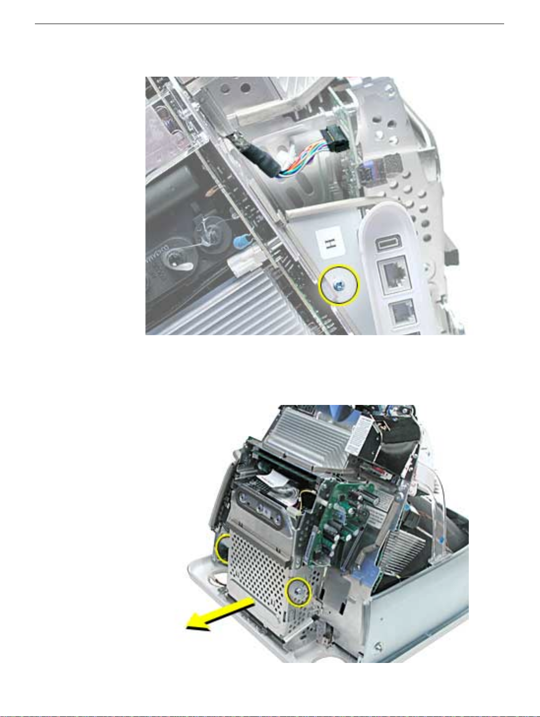
5. Remove one screw on the I/O panel and disconnect the video cable located above the
screw. Squeeze the tabs to disconnect the video cable.
6.
Note:
Remove the AirPort card if it’s installed. Grab onto the digital module at the tabs
circled below. Pull in the direction of arrow. The digital module is connected to blindmate connectors. It’s a tight fit, so pull hard.
Digital Module Assembly
eMac Take Apart -
25
Page 29
IVAD Cable
Important: Take Apart Note: Replace the IVAD cable if the eMac raster shifts upward
from the bottom of the display or the raster is jumpy, otherwise leave the cable alone.
Refer to Knowledge Base article 95168 for more information.
Tools
This procedure requires the following tools:
• 2.5 mm hex tool
• Phillips #2 screwdriver
• Hot-melt glue gun (recommended)
• Nylon probe tool (922-5065)
Procedure
1. Remove the rear housing from the eMac.
Discharge the CRT. Warning: This product contains high voltage and a high-vacuum
2.
picture tube. To prevent injury, review the Service Foundations course: “CRT Displays”
for safety information.
3. Locate the IVAD assembly shown below.
26
eMac Take Apart
IVAD Cable
Page 30
4. Note: The screws on IVAD assembly need to be removed to access one end of the
IVAD cable. Remove the screw (circled below) and then remove the metal
cable cover.
5. Remove the remaining two screws on the IVAD assembly.
IVAD Cable
eMac Take Apart - 27
Page 31

6. With the nylon probe tool or needlenose pliers, remove the glue from the
connector.
Note: If you find it difficult removing the glue use a heat gun to
soften the glue a bit and then remove it. Disconnect the cable after removing
the glue.
7. Locate the other end of the IVAD cable.
28 eMac Take Apart
IVAD Cable
Page 32

8. With the nylon probe tool or needlenose pliers, remove the glue from the
cable connector.
Note: If you find it difficult removing the glue use a heat gun
to soften the glue a bit and then remove it.
9. Clip the cable tie. Disconnect the IVAD cable from the board.
IVAD Cable
eMac Take Apart - 29
Page 33

IVAD Cable Replacement Procedure
1. Install the replacement IVAD cable.
2. Replace the cable tie (shown on the previous page).
3. Place hot glue on each end of the IVAD connector.
4. Reassemble the computer and test the system.
30 eMac Take Apart
IVAD Cable
Page 34

AirPort Card Guide
Tools
This procedure requires the following tools:
• Phillips #2
Part Location
AirPort Card Guide
Preliminary Steps
Before you begin, do the following:
• Place the computer face down on an ESD mat.
• Remove the user access door.
• Remove the feet.
• Remove the rear housing.
eMac Take Apart - 31
Page 35

• Discharge the CRT.
• Remove the fan.
• Remove the Faraday cage.
• Remove the digital module assembly.
Procedure
1. Remove the two screws connecting the guide to the chassis.
32 eMac Take Apart
AirPort Card Guide
Page 36

2. Lift the AirPort card guide in the direction of the arrow to unhook the metal tabs
(circled) on the chassis. Disconnect the antenna from the AirPort card guide Note:
Tape the antenna to the bottom of the unit while in for service.
AirPort Card Guide
eMac Take Apart - 33
Page 37

LED
Tools
This procedure requires the following tools:
• Phillips #2
Part Location
Preliminary Steps
Before you begin, do the following:
• Place the computer face down on an ESD mat.
• Remove the user access door.
• Remove the feet.
• Remove the rear housing.
• Discharge the CRT.
34 eMac Take Apart
LED
Page 38

• Remove the fan.
• Remove the Faraday cage.
• Remove the digital module assembly.
Procedure
1. Remove one screw and disconnect the LED cable. Important: The connector is very
fragile, remove it gently. Lift the LED board off the LED reflector.
LED
eMac Take Apart - 35
Page 39

2. Note: The LED consists of two parts; the LED board and the LED reflector (black
plastic piece shown below). Remove the LED reflector from the bezel.
36 eMac Take Apart
LED
Page 40

Front Bezel
Tools
This procedure requires the following tools:
• Phillips #2
Part Location
Front Bezel
Preliminary Steps
Before you begin, do the following:
• Place the computer face down on an ESD mat.
• Remove the user access door.
• Remove the feet.
• Remove the rear housing.
• Discharge the CRT.
• Remove the fan.
eMac Take Apart - 37
Page 41

• Remove the Faraday cage.
• Remove the digital module assembly.
38 eMac Take Apart
Front Bezel
Page 42

Procedure
1. Remove the eight bezel screws. There are three on each side and two at the top of the
bezel.
2. Important: DO NOT remove the two larger screws shown below, or the two screws
shown in the next photo. DO NOT remove these larger screws. If they are removed,
the CRT will be out of alignment and the entire display/analog assembly will need to
be replaced.
Front Bezel
eMac Take Apart - 39
Page 43

3. Do Not remove these CRT screws either.
4. Disconnect the microphone cable.
5. Carefully lift the display/analog assembly off the bezel.
40 eMac Take Apart
Front Bezel
Page 44

Antenna Board
Tools
This procedure requires the following tools:
• Phillips #2 screwdriver
• Needlenose pliers
Part Location
Antenna Board
Preliminary Steps
Before you begin, do the following:
• Place the computer face down on an ESD mat.
• Remove the user access door.
• Remove the feet.
• Remove the rear housing.
• Discharge the CRT.
• Remove the fan.
• Remove the Faraday cage.
eMac Take Apart - 41
Page 45

• Remove the front bezel.
• Remove the digital module assembly.
Procedure
1. Remove one screw and pinch the standoff with a needlenose pliers to release the
antenna board from the divider panel.
42 eMac Take Apart
Antenna Board
Page 46

2. Carefully position the computer on it’s base. Facing the CRT, locate the metal antenna
bracket at the top of the CRT. Remove the screw attached to the bracket.
3. Carefully pry the antenna cable from the two clips on the side of the CRT.
Antenna Board
eMac Take Apart - 43
Page 47

Microphone
Tools
This procedure requires the following tools:
• Phillips #2
Part Location
Preliminary Steps
Before you begin, do the following:
• Place the computer face down on an ESD mat.
• Remove the user access door.
• Remove the feet.
• Remove the rear housing.
• Discharge the CRT.
• Remove the fan.
44 eMac Take Apart
Microphone
Page 48

• Remove the Faraday cage.
• Remove the digital module assembly.
• Remove the front bezel.
Procedure
1. Remove the microphone cable from the bezel. Replacement Note: When replacing
the microphone into the bezel, the metal faces down, the dimple faces up.
Microphone
eMac Take Apart - 45
Page 49

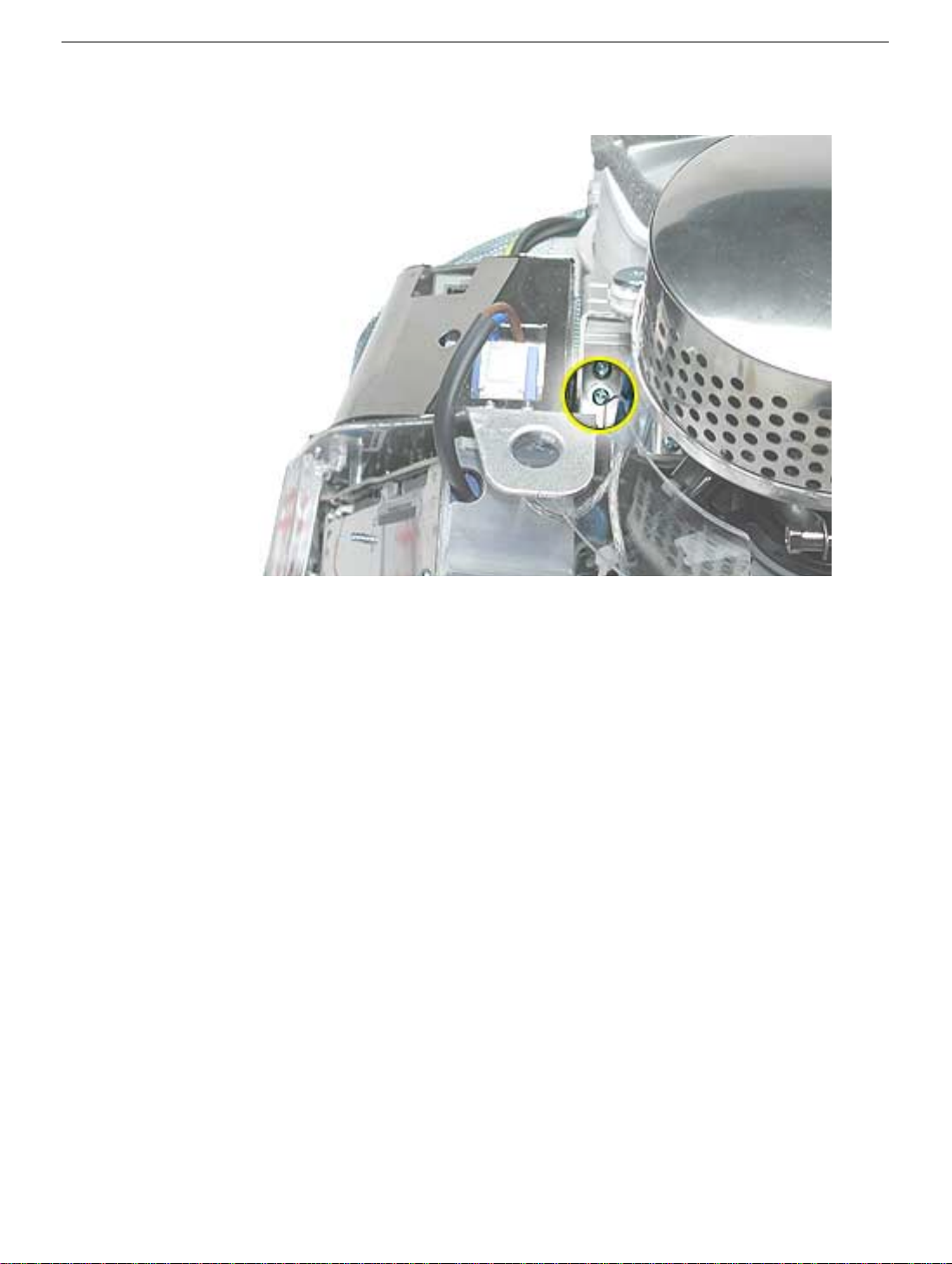
Down Converter
Tools
This procedure requires the following tools:
• Phillips #2
Part Location
Preliminary Steps
Before you begin, do the following:
• Place the computer face down on an ESD mat.
• Remove the user access door.
• Remove the feet.
• Remove the rear housing.
• Discharge the CRT.
• Remove the fan.
• Remove the Faraday cage.
46 eMac Take Apart
Down Converter
Page 50

Procedure
1. With the down converter still attached to the digital module, remove the screw shown
below.
2. Looking at the digital module from the back, remove the second screw.
Down Converter
eMac Take Apart - 47
Page 51

3. Disconnect the down converter from the logic board by holding the board at the top
and the bottom and gently rock the board in the direction of the arrow.
48 eMac Take Apart
Down Converter
Page 52

Door Assembly
Tools
This procedure requires the following tools:
• Phillips #2
Part Location
Preliminary Steps
Before you begin, do the following:
• Place the computer face down on an ESD mat.
• Remove the user access door.
• Remove the feet.
• Remove the rear housing.
• Discharge the CRT.
• Remove the fan.
Door Assembly
eMac Take Apart - 49
Page 53

• Remove the Faraday cage.
• Remove the digital module assembly.
Procedure
1. Remove the two screws connecting the door to the front bezel.
2. Remove the door from the front bezel. Replacement Note: Transfer the serial number
label on the inside of the door to the replacement door.
50 eMac Take Apart
Door Assembly
Page 54

Hard Drive
Tools
This procedure requires the following tools:
• Phillips #2
• Jeweler’s #1 screwdriver
Part Location
Preliminary Steps
Before you begin, do the following:
• Place the computer face down on an ESD mat.
• Remove the user access door.
• Remove the feet.
• Remove the rear housing.
• Discharge the CRT.
Hard Drive
eMac Take Apart - 51
Page 55

• Remove the fan.
• Remove the Faraday cage.
• Remove the digital module assembly.
Procedure
1. Remove the three screws along the back of the hard drive.
52 eMac Take Apart
Hard Drive
Page 56

2. WIth a screwdriver or plastic tool, pry the hard drive out of the hard drive carrier to
access the power and data cables.
Hard Drive
eMac Take Apart - 53
Page 57

3. Disconnect the hard drive power cable and the hard drive data cable. Remove the
drive from the carrier. Notice the three thermal pads on the hard drive; two on the top
and one along the side of the drive. Replace the thermal pads if they are damaged.
54 eMac Take Apart
Hard Drive
Page 58

4. Turn the hard drive over. WIth a jeweler’s screwdriver, remove the two screws on the
black plastic cover and the two screws on the metal bracket. Note: These two pieces
need to be removed when returning the hard drive to Apple service.
Hard Drive
eMac Take Apart - 55
Page 59

Hard Drive Carrier
Tools
This procedure requires the following tools:
• Phillips #2 screwdriver
Part Location
Preliminary Steps
Before you begin, do the following:
• Place the computer face down on an ESD mat.
• Remove the user access door.
• Remove the feet.
• Remove the rear housing.
• Discharge the CRT.
• Remove the fan.
56 eMac Take Apart
Hard Drive Carrier
Page 60

• Remove the Faraday cage.
• Remove the digital module assembly.
• Remove the hard drive.
Procedure
1. Remove the seven carrier screws. Peel back the EMI tape on the on both sides of the
carrier.
2. Lift the carrier off the logic board.
Hard Drive Carrier
eMac Take Apart - 57
Page 61

Logic Board Heatsink
Tools
This procedure requires the following tools:
• Screwdriver to pry the heatsink clip
Part Location
Preliminary Steps
Before you begin, do the following:
• Place the computer face down on an ESD mat.
• Remove the user access door.
• Remove the feet.
• Remove the rear housing.
• Discharge the CRT.
• Remove the fan.
• Remove the Faraday cage.
• Remove the digital module assembly.
58 eMac Take Apart
Logic Board Heatsink
Page 62

• Remove the hard drive.
• Remove the hard drive carrier.
Procedure
1. With a screwdriver, pry the heatsink clip out of the hole on the logic board.
2. Lift the heatsink off the logic board. Replacement Note: Whenever the heatsink is
removed, the bottom side of the heatsink and the top of the microprocessor must be
cleaned and thermal paste must be applied to the microprocessor. If the mating
surfaces are not cleaned and thermal paste is not applied, the CPU may overheat and
become damaged. Refer to the next topic, “Thermal Paste Application”.
Logic Board Heatsink
eMac Take Apart - 59
Page 63

Thermal Paste Application
The microprocessor uses a heatsink/thermal pipe to transfer heat away. Whenever the
heatsink is removed, the bottom side of the heatsink and the top of the microprocessor
must be cleaned and thermal paste must be applied. If the mating surfaces are not
cleaned and thermal paste is not applied, the CPU may overheat and become damaged.
Tools
This procedure requires the following tools:
• Plastic stylus or nylon probe tool (922-5065) to remove the old thermal paste
• Thermal paste (922-4757), each tube contains 4-5 applications
Procedure
1. Thoroughly clean the thermal film from the heatsink surface with a plastic stylus or the
nylon probe tool. Do not use an abrasive material or liquid cleaner. Important: Be
extremely careful not to bend the heatpipes on the heatsink.
60 eMac Take Apart
Logic Board Heatsink
Page 64

2. Carefully clean the surface of the microprocessor with a plastic stylus or nylon probe
tool (922-5065) to remove the old thermal paste.
3.
Squeeze a drop of thermal paste onto the middle of the microprocessor as
shown.
Logic Board Heatsink
eMac Take Apart - 61
Page 65

4. Spread the paste evenly over the processor. Important: On this product, it is critical
to spread the paste over the processor , or the chip could overheat.
5. Reinstall the heatsink and heatsink clip.
62 eMac Take Apart
Logic Board Heatsink
Page 66

Logic Board
Tools
This procedure requires the following tools:
• Phillips #2 screwdriver
Part Location
Preliminary Steps
Before you begin, do the following:
• Place the computer face down on an ESD mat.
• Remove the user access door.
• Remove the feet.
• Remove the rear housing.
• Discharge the CRT.
• Remove the fan.
• Remove the Faraday cage.
Logic Board
eMac Take Apart - 63
Page 67

• Remove the digital module assembly.
• Remove the hard drive.
• Remove the down converter.
• Remove the hard drive carrier.
• Remove the logic board heatsink.
Procedure
1. Carefully position the assembly on the optical drive door. Disconnect the optical data
cable and the optical power cable.
64 eMac Take Apart
Logic Board
Page 68

2. Turn the assembly so the logic board is facing up. Remove the four screws on the logic
board. Note: The screw in the bottom left corner is different from the other three
screws. It is self-tapping with no collar.
3. Lift the logic board off the optical assembly. Before returning the board to Apple,
remove the following items:
• I/O panel
• RJ-11 connector (if present)
• Modem board
• SDRAM
• Warning: The microprocessor uses a heatsink/thermal pipe to transfer heat away.
Whenever the heatsink is removed, the bottom side of the heatsink and the top of
the microprocessor must be cleaned and thermal paste must be applied to the
microprocessor. If the mating surfaces are not cleaned and thermal paste is not
applied, the CPU may overheat and become damaged. Refer to “Thermal Paste
Application” in this chapter.
Logic Board
eMac Take Apart - 65
Page 69

Memory
Tools
• No tools are required for this procedure
Part Location
Note: Memory can be accessed through the user access door on the back of the
computer.
Preliminary Steps
Before you begin, do the following:
• Place the computer face down on an ESD mat.
• Unplug all cables except the power cord, from the computer.
• Remove the user access door.
66 eMac Take Apart
Memory
Page 70

Procedure
1. Touch a metal surface inside the computer. Then unplug the computer. Important:
Always do this before you touch any parts, or remove/install any components inside
the computer. To avoid generating static electricity, do not walk around until you have
finished removing or installing the memory and closed the computer.
Memory
eMac Take Apart - 67
Page 71

2. Locate the memory module.
3. Push the ejectors on the memory slot outward and down (#1) so they are in the open
position. Remove the memory module (#2). Replacement Note: The memory is
designed to fit into the slot only one way. Be sure to align the notches on the module
with the small notches inside the slot.
68 eMac Take Apart
Memory
Page 72

Battery
Tools
• No tools are required for this procedure
Part Location
Note: The battery can be accessed through the user access door on the back of the
computer.
Battery
Preliminary Steps
Before you begin, do the following:
• Place the computer face down on an ESD mat.
• Unplug all cables except the power cord, from the computer.
• Remove the user access door.
eMac Take Apart - 69
Page 73

Procedure
1. Touch a metal surface inside the computer. Then unplug the computer. Important:
Always do this before you touch any parts, or remove/install any components inside
the computer. To avoid generating static electricity, do not walk around until you have
finished removing or installing the battery and closed the computer.
2. WIth a screwdriver or anti-static tool, carefully pry the battery out of the battery holder.
70 eMac Take Apart
Battery
Page 74

I/O Panel
Tools
This procedure requires the following tools:
• Phillips #2 screwdriver
Part Location
I/O Panel
Preliminary Steps
Before you begin, do the following:
• Place the computer face down on an ESD mat.
• Remove the user access door.
• Remove the feet.
• Remove the rear housing.
• Discharge the CRT.
• Remove the fan.
• Remove the Faraday cage.
• Remove the digital module assembly.
eMac Take Apart - 71
Page 75

Procedure
1. Remove the two I/O panel screws.
2. Remove the I/O panel off the logic board.
72 eMac Take Apart
I/O Panel
Page 76

Modem
Tools
This procedure requires the following tools:
• Phillips #1 or jeweler’s screwdriver
Part Location
Modem
Preliminary Steps
Before you begin, do the following:
• Place the computer face down on an ESD mat.
• Remove the user access door.
• Remove the feet.
• Remove the rear housing.
• Discharge the CRT.
• Remove the fan.
• Remove the Faraday cage.
• Remove the digital module assembly.
eMac Take Apart - 73
Page 77

Procedure
1. Remove the two modem screws.
2. Disconnect the RJ-11 cable from the modem. Remove the modem.
74 eMac Take Apart
Modem
Page 78

RJ-11 cable
Tools
No tools are required for this procedure
Part Location
RJ-11 cable
Preliminary Steps
Before you begin, do the following:
• Place the computer face down on an ESD mat.
• Remove the user access door.
• Remove the feet.
• Remove the rear housing.
• Discharge the CRT.
• Remove the fan.
• Remove the Faraday cage.
eMac Take Apart - 75
Page 79

• Remove the digital module assembly.
• Remove the I/O panel
Procedure
1. Disconnect the RJ-11 cable from the modem.
2. With an anti-static tool, push and then pull the RJ-11 port off the logic board.
76 eMac Take Apart
RJ-11 cable
Page 80

Optical Drive
Tools
This procedure requires the following tools:
• Phillips #2 screwdriver
Part Location
Optical Drive
Preliminary Steps
Before you begin, do the following:
• Place the computer face down on an ESD mat.
• Remove the user access door.
• Remove the feet.
• Remove the rear housing.
• Discharge the CRT.
• Remove the fan.
• Remove the Faraday cage.
• Remove the digital module assembly.
• Remove the hard drive.
• Remove the heatsink.
• Remove the logic board.
eMac Take Apart - 77
Page 81

Procedure
1. Remove two screws on the right side of the optical carrier.
2. Remove two screws on the left side of the optical carrier.
78 eMac Take Apart
Optical Drive
Page 82

3. Flip the optical carrier over and disconnect the optical power cable and the optical
data cable.
4. Remove the cotter pin (#1) from the carrier. Next, lift the heatshield by the metal fence
(#2), and lastly remove the heatshield in the direction of the arrow (#3) to detach it
from the carrier.
Optical Drive
eMac Take Apart - 79
Page 83

5. Slide the optical drive out of the carrier by pushing it from the back end where the EMI
cap is located. Note: The EMI cap is not attached to the carrier or the optical drive.
80 eMac Take Apart
Optical Drive
Page 84

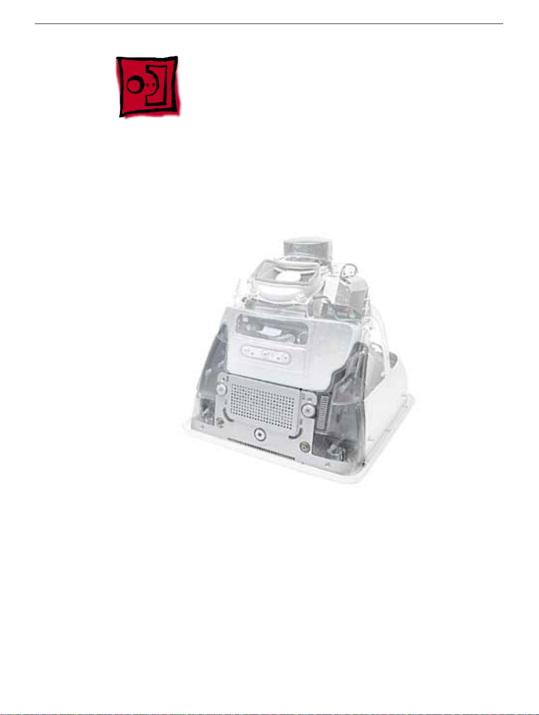
Display/Analog Assembly
Tools
This procedure requires the following tools:
• No tools are required
Warning: This product contains high voltage and a high-vacuum picture tube. To prevent
injury, always review CRT Safety on Service Source online. This link can be found under
the list of topics under the iMac icon. Remember, never use a grounding wriststrap until
after discharging the CRT and setting up an ongoing ground connection.
Note: The eMac display/analog assembly requires no voltage calibration or geometry
adjustment. Should the display require adjustment (focus, color, or brightness) use the
“Displays” pane under System Preferences if using Mac OS X. If using Mac OS 9, use the
Monitor Control Panel to make adjustments. If you can not make satisfactory corrections
with these tools, replace the display/analog assembly.
Part Location
Display/Analog Assembly
eMac Take Apart - 81
Page 85

Preliminary Steps
Before you begin, do the following:
• Place the computer face down on an ESD mat.
• Remove the user access door.
• Remove the feet.
• Remove the rear housing.
• Discharge the CRT.
• Remove the fan.
• Remove the Faraday cage.
• Remove the digital module assembly.
• Remove the AirPort card guide.
• Remove the front bezel
• Remove the antenna.
If you remove everything listed in the preliminary steps above, you are left with the display/
analog module. There is nothing more to remove from this module.
Note: The display/analog assembly contains a non-switching power supply which is preset
at a 220V configuration.The voltage selection needs to be manually set by the way of a
voltage jumper. This means if you are operating the computer in a 110V environment, you
will have to install the voltage jumper. Refer to the Troubleshooting chapter, “Digital/
Analog”
Replacement Note: If you are returning a defective display/analog module, it is imperative
that proper packaging guidelines be followed. The packing procedure is included with the
replacement assembly. Incorrect packaging can result in damaged eMac displays. Please
read and follow the directions enclosed in the shipping box of the new display prior to
packaging the defective module.
Failure to package the defective module according to the instructions may result in liability
for the cost of the damaged display.
82 eMac Take Apart
Display/Analog Assembly
Page 86

LHR Coil
Tools
This procedure requires the following tools:
• Phillips #2 screwdriver
Part Location
Note: This part is used in Europe for line conditioning. If your computer does not have the
LHR, skip this procedure.
LHR Coil
Preliminary Steps
Before you begin, do the following:
• Place the computer face down on an ESD mat.
• Remove the user access door.
• Remove the feet.
• Remove the rear housing.
• Discharge the CRT.
eMac Take Apart - 83
Page 87

Procedure
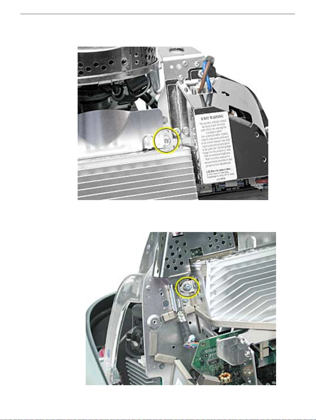
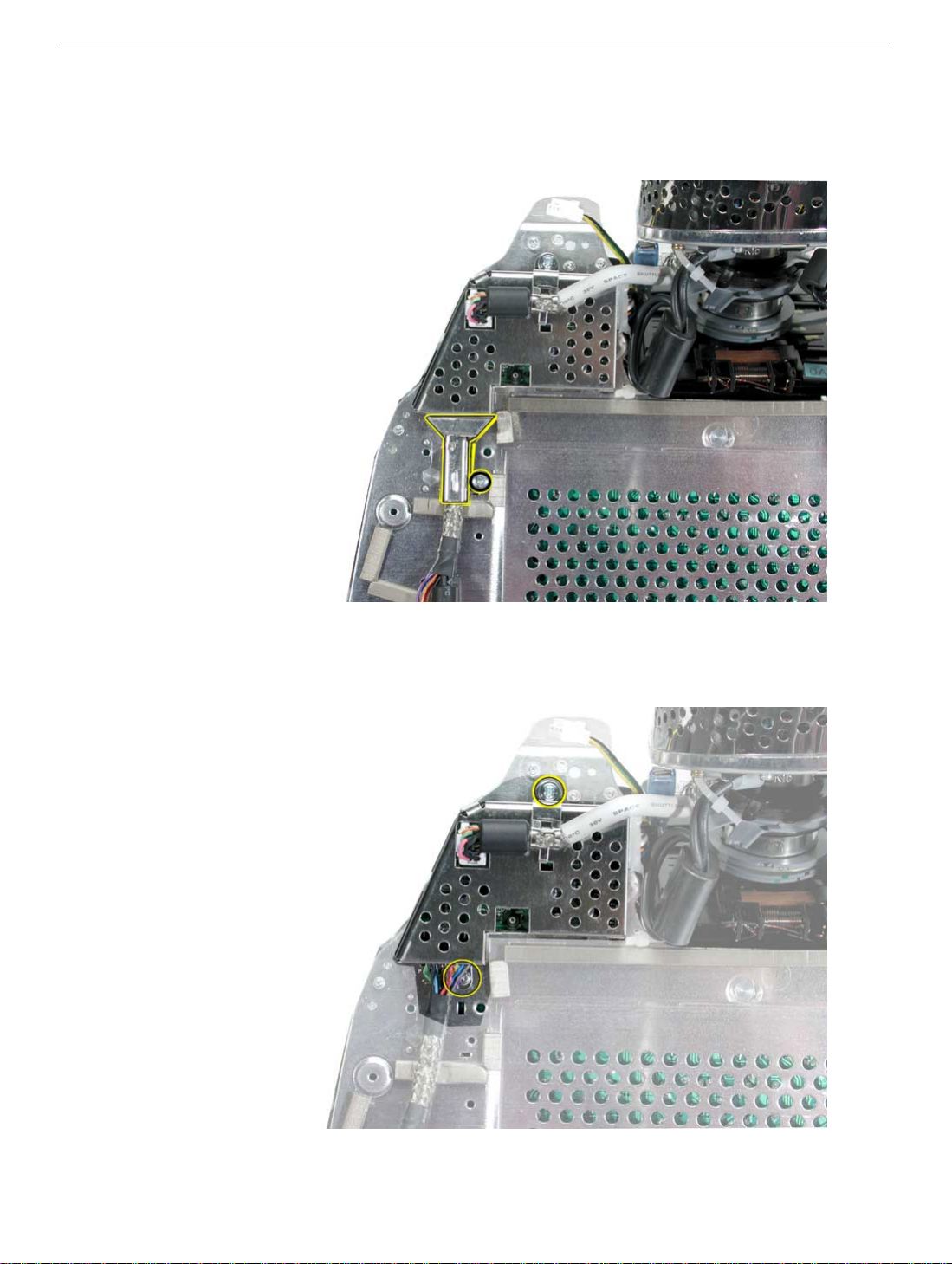
1. Remove the screw located at the bottom of the LHR module.
2. Disconnect the LHR connector located next to the fuse and to the right of the fan.
84 eMac Take Apart
LHR Coil
Page 88

3. Disengage the tabs on the LHR. Note: The tabs (circled below) clip into the divider
panel. Remove the LHR from the divider panel.
LHR Coil
eMac Take Apart - 85
Page 89

Service Source
Troubleshooting
eMac
© 2002 Apple Computer, Inc. All rights reserved.
Page 90

General Information
What’s New
1. Important: The display/analog assembly contains a non-switching power supply preset at a 220V
configuration. The voltage selection needs to be manually set by the way of a voltage jumper. If you are
operating the computer in a 110V environment, you will have to install the voltage jumper. Refer to
“Display/Analog Voltage Setting and LHR Module Instructions” discussed later in this chapter.
Note: The LHR coil (line conditioning module) is used in some international countries. Refer to the Take
Apart chapter, LHR topic, for take-apart information.
2. Important: If you are returning a defective display/analog assembly, it is imperative that proper
packaging guidelines be followed. The packing procedure is included with the replacement assembly.
Incorrect packaging can result in damaged eMac displays. Please read and follow the directions
enclosed in the shipping box of the new display prior to packaging the defective module.Failure to
package the defective module according to the instructions may result in liability for the cost of the
damaged display.
3. Important: Do NOT lift, handle, bump, or manipulate the CRT neck/neck board on the Display/Analog
assembly. Modules damaged by mishandling are NOT covered by Apple Warranty. Apple Authorized
Service Providers can be liable for broken CRT necks due to improper handling. Refer to “CRT Neck/
Display/Analog Assembly Handling Information” topic in this chapter for more information.
4. The eMac display/analog assembly requires no voltage calibration or geometry adjustment. Should the
display appear to require adjustment (focus, color, or brightness) use the “Displays” pane under System
Preferences if using Mac OS X. If using Mac OS 9, use the Monitor Control Panel. If you can not make
satisfactory corrections with these tools, replace the display/analog assembly.
5. Important: The microprocessor uses a heatsink/thermal pipe to transfer heat away. Whenever the
heatsink is removed, the bottom side of the heatsink and the top of the microprocessor must be cleaned
and thermal paste must be applied to the microprocessor. If the mating surfaces are not cleaned and
thermal paste is not applied, the CPU may overheat and become damaged. Refer to “Thermal Paste
Application” in this chapter.
6. The hard drive has 3 thermal pads. If the thermal pads become damaged, replace them.
7. The eMac has an optional stand. Refer to the Upgrades chapter or the CIP procedures for instructions
on how to install the stand.
8. The computer has a Power PC G4 microprocessor, running at a clock speed of 700 MHz.
9. The computer comes with 128 MB of SDRAM installed. Two DIMM slots support up to 1 GB using 128
MB, 256 MB, or 512 MB DIMMs. The SDRAM modules are PC-100, 168-pin DIMMs.
10. The computer comes with either tray-loading CD-ROM or DVD-ROM/CD-RW (combo drive).
General Information
eMac Troubleshooting - 1
Page 91

11. The 56K fax modem is only available on the DVD-ROM/CD-RW (combo drive) model.
12. The eMac uses a different A/C power cord; power cords from older iMac models may not fit into the A/
C socket.
2 - eMac Troubleshooting
General Information
Page 92

Logic Board, Top
Slots
SDRAM
PMU Reset Button Battery Hard Drive Connector
General Information
VGA Output Port
Ethernet Port
Internal Modem Port
(Not Shown)
FireWire Ports
USB Ports
Sound Input
Port
Sound Output
Port
eMac Troubleshooting - 3
Page 93

Logic Board, Bottom
Video Processor
Blind Mate Connector
G4 Microprocessor
4 - eMac Troubleshooting
AirPort Slot
Blind Mate Connector
General Information
Page 94

I/O Ports
General Information
eMac Troubleshooting - 5
Page 95

The PMU Chip
The PMU (Power Management Unit) is a micro controller chip that controls all power functions
for the computer. The PMU is a computer within a computer. It has memory, software,
firmware, I/O, two crystals, and a CPU. Its function is to:
• Tell the computer to turn on, turn off, sleep, wake, idle, etc.
• Manage system resets from various commands.
• Maintain parameter RAM (PRAM).
• Manage the real-time clock.
Important: The PMU is very sensitive and touching the circuitry on the logic board can cause the
PMU to crash. If the PMU crashes, the battery life goes from about five years to about two days if
the PMU is not reset. Refer to the next topic, “Resetting the PMU on the Logic Board” for the
procedure.
Many system problems can be resolved by resetting the PMU chip. The PMU reset button is
located behind the user access door, refer to the graphic below.
Location of the PMU Reset Button
6 - eMac Troubleshooting
General Information
Page 96

Resetting the PMU on the Logic Board
Resetting the PMU (Power Management Unit) on the logic board can resolve many system
problems. Whenever you have a unit that fails to power up, you should follow this procedure
before replacing any modules.
1. Save open documents and quit all open applications.
2. Turn the computer off by choosing Shut Down from the Special menu (if using Mac OS 9), or choose
Shut Down from the Apple menu if using OS X.
3. Remove the user access door.
General Information
eMac Troubleshooting - 7
Page 97

4 Unplug all cables, except the power cord, from the computer.
5 Touch a metal surface inside the computer. Then unplug the power cord.This helps protect the
computer from damage caused by electrostatic discharge. Important: To avoid electrostatic
discharge, always ground yourself by touching metal before you touch any parts or install components
inside the computer. To avoid generating static electricity, do not walk around the room until you have
finished the procedure and closed the computer.
8 - eMac Troubleshooting
General Information
Page 98

6 Press the PMU reset button (shown below) once and then proceed to step 7. Do NOT press the
PMU reset button a second time because it could crash the PMU chip.
7 WAIT ten seconds before connecting the power cord and powering the computer on. If the
computer powers on, go to the next step. If the computer does not power on, there is something
else wrong with the computer, refer to the symptom/cure, “No Power” in this chapter.
8 Run MacTest Pro and return the computer to the customer.
Note: This entire procedure resets the computer’s PRAM. Be sure to reset the computer’s time,
date and other system parameter settings before returning the computer to the customer.
General Information
eMac Troubleshooting - 9
Page 99

Power-On Self Test
There is a power-on self test that resides in the ROM of the eMac. This test automatically runs
whenever the eMac is powered on after being fully shut down (the power-on self test does not
run if the machine is only restarted).
If a problem is detected during the test, you will not hear a normal startup chime. Instead, the
system will beep as explained below. Refer to “Error Beeps” later in this chapter for
instructions on how to troubleshoot and repair an eMac that sounds error beeps at startup time.
Following is a definition of what the error beeps at startup time signify.
One Beep: No RAM is installed or detected.
Two Beeps: Incompatible memory is installed. (The slots accept standard PC-100 or PC-
133, 168-pin DIMMs).
Three Beeps: No RAM banks passed memory testing.
Four or Five Beeps: Bad checksum for the remainder of the boot ROM. The ROM is bad.
10 - eMac Troubleshooting
General Information
Page 100

Logic Board Battery
Important: Apple highly recommends removing the battery when handling the logic board. Make
sure to use proper ESD protection when handling modules.
The battery on the logic board controls the stored system settings, such as date and time. It is only
necessary to test the battery when you can’t power on the computer, or the date and time are reset
every time the AC power is removed.
The battery is also used to power the PMU chip (because the PMU chip keeps time and must always
be running) when the computer is unplugged from the wall (AC power). The PMU is
and touching any circuitry that is connected to the PMU can cause it to crash. If the PMU crashes,
the battery life goes from about five years to about two days if the PMU is not reset. Once the
battery goes dead, the PMU will reset the time and date every time the AC power is removed. To fix
this situation, replace the battery and reset the PMU (refer to “Resetting the PMU on the Logic
Board” mentioned earlier in this chapter).
very sensitive
Testing the Battery
If the computer has a “No Power” situation, check the battery before replacing modules. A drained
battery may be indicative of a crashed Power Management Unit.
With the battery in the battery holder (under load), measure the voltage across the battery’s
positive and ground terminals.
Does the battery measure at least +3.5v? If not, replace the battery and reset the PMU. If the
battery does measure over +3.5v, reinstall the battery and reset the PMU as above
Connect the power cord and power up the system again.
General Information
eMac Troubleshooting - 11
 Loading...