

Page 1

Service Source
Apple Cinema Display 22" LCD
(ADC)
11 April 2003
© 2003 Apple Computer, Inc. All rights reserved.
Page 2

Service Source
Take Apart
Apple Cinema Display 22" LCD (ADC)
© 2003 Apple Computer, Inc. All rights reserved.
Page 3

Tools
The following tools are recommended for the take apart procedures.
• 2 mm hex key
• #2 Phillips screwdriver
• jeweler’s #1 Phillips screwdriver
• ESD wriststrap and mat
• white cotton gloves (922-1592)
• nylon probe tool (922-5065)
Important:
Be very careful with tools, lay the display and plastic parts only on a clean soft surface,
and wear clean white cotton gloves when handling and servicing the display.
The display plastics, inside and out, retain fingerprints and can scratch easily.
Tools
Apple Cinema Display 22" (ADC) Take Apart -
1
Page 4
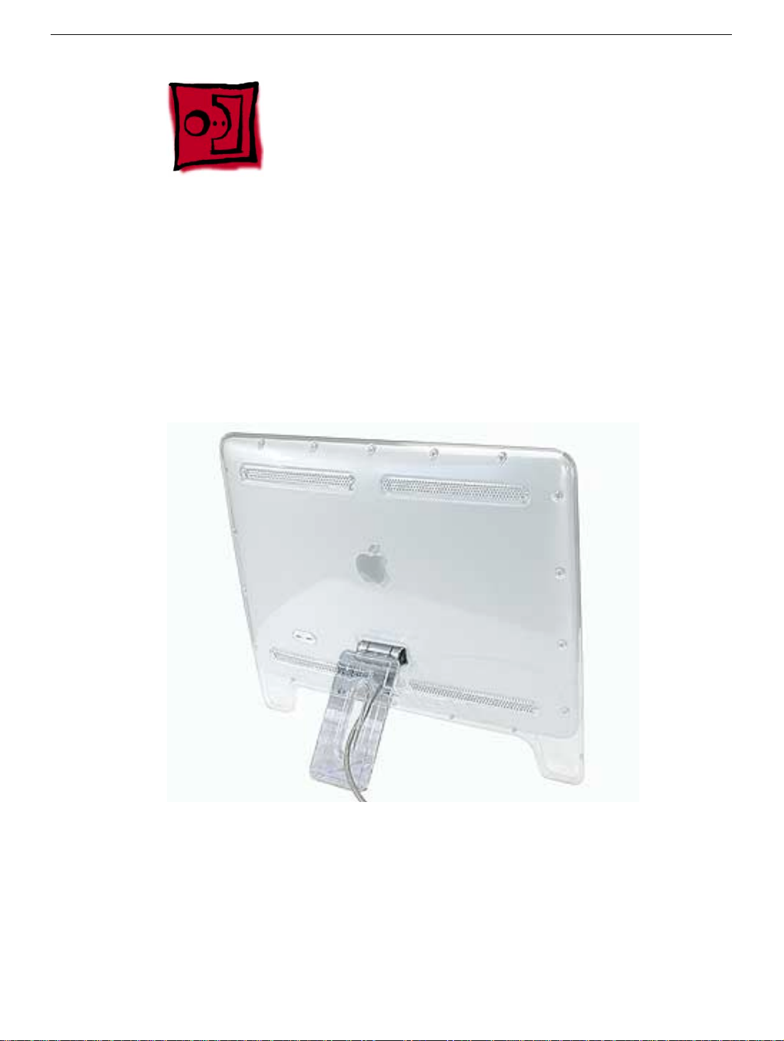
Foot Assembly
Tools
This procedure requires the following tools:
• 2 mm hex key
• White gloves for handling plastics
Part Location
Preliminary Steps
Before you begin, do the following:
• Place the display face down on an ESD mat or soft cloth
Note:
Plastics are easily damaged. The white gloves prevent fingerprints.
2 -
Apple Cinema Display 22" (ADC) Take Apart
Foot Assembly
Page 5
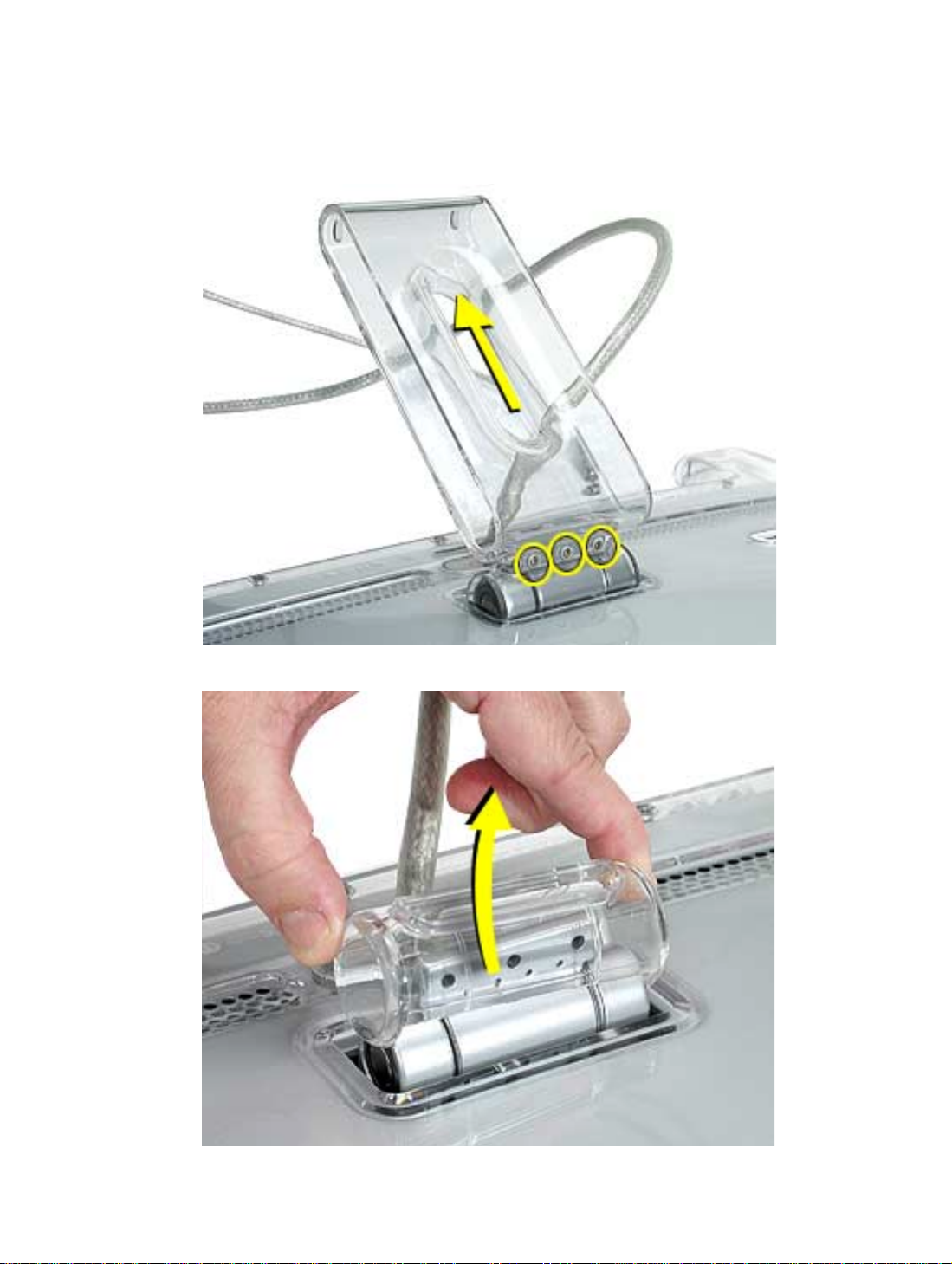
Procedure
1. Remove three hex screws.
2. Lift the foot off the hinge.
3. The clear hinge cap may fall off the foot. If it doesn’t, remove it from the foot.
4. Pull the ADC (Apple Display Connector) cable through the opening in the foot to
separate the foot and the cable.
Foot Assembly
Apple Cinema Display 22" (ADC) Take Apart -
3
Page 6
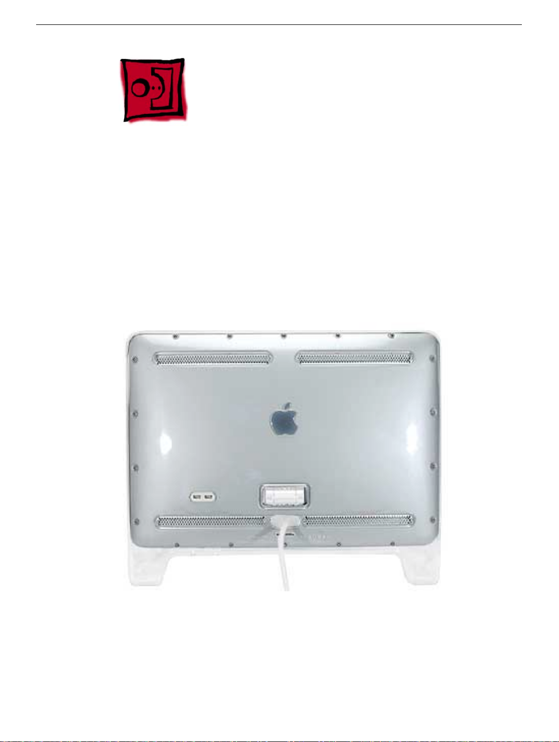
Rear Cover
Tools
This procedure requires the following tools:
• 2 mm hex key
• White gloves for handling plastics
Note:
Plastics are easily damaged. The white gloves prevent fingerprints.
Part Location
Preliminary Steps
Before you begin, do the following:
• Place the display face down on an ESD mat
• Remove the foot assembly
4 -
Apple Cinema Display 22" (ADC) Take Apart
Rear Cover
Page 7
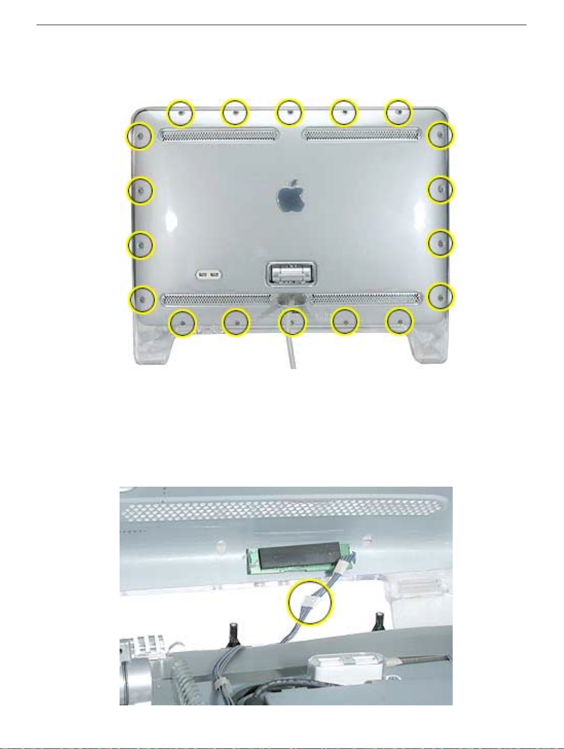
Procedure
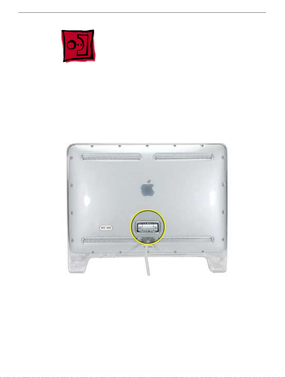
1. Remove eighteen hex screws on the rear cover.
2. Lift the rear cover slightly and disconnect the power/brightness switch cable
connector, shown below. Carefully pull the ADC cable through the rear cover.
Note:
The power/brightness switch board is permanently attached to the rear cover
and cannot be removed.
Replacement Note:
socket, and that the USB icon arrows point up.
Verify that the clear plastic USB cover is in place over the USB
Rear Cover
Apple Cinema Display 22" (ADC) Take Apart -
5
Page 8
Hinge
Tools
This procedure requires the following tools:
• #2 Phillips screwdriver
Part Location
Preliminary Steps
Before you begin, do the following:
• Place the display face down on an ESD mat
• Remove the foot assembly
• Remove the rear cover
6 -
Apple Cinema Display 22" (ADC) Take Apart
Hinge
Page 9
Procedure
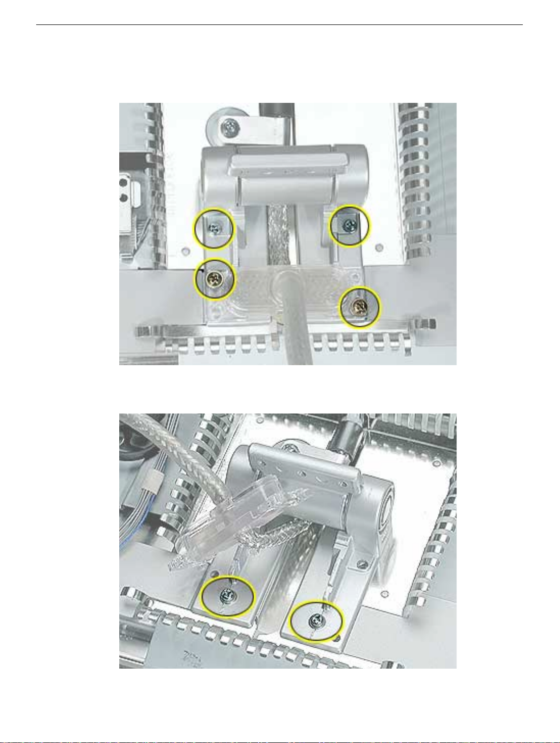
1. Remove four screws.
ADC cable.
Note:
Two of the screws are yellow. These screws are for the
2. Pull the ADC cable out of the way and remove two more hinge screws.
3. Lift the hinge up and off the chassis.
Hinge
Replacement Note:
The hinge has locators on it, so it seats correctly in the chassis.
Apple Cinema Display 22" (ADC) Take Apart -
7
Page 10
Main Board Shield
Tools
This procedure requires the following tools:
• #2 Phillips screwdriver
Part Location
Preliminary Steps
Before you begin, do the following:
• Place the display face down on an ESD mat
• Remove the foot assembly and hinge cover
• Remove the rear cover
8 -
Apple Cinema Display 22" (ADC) Take Apart
Main Board Shield
Page 11
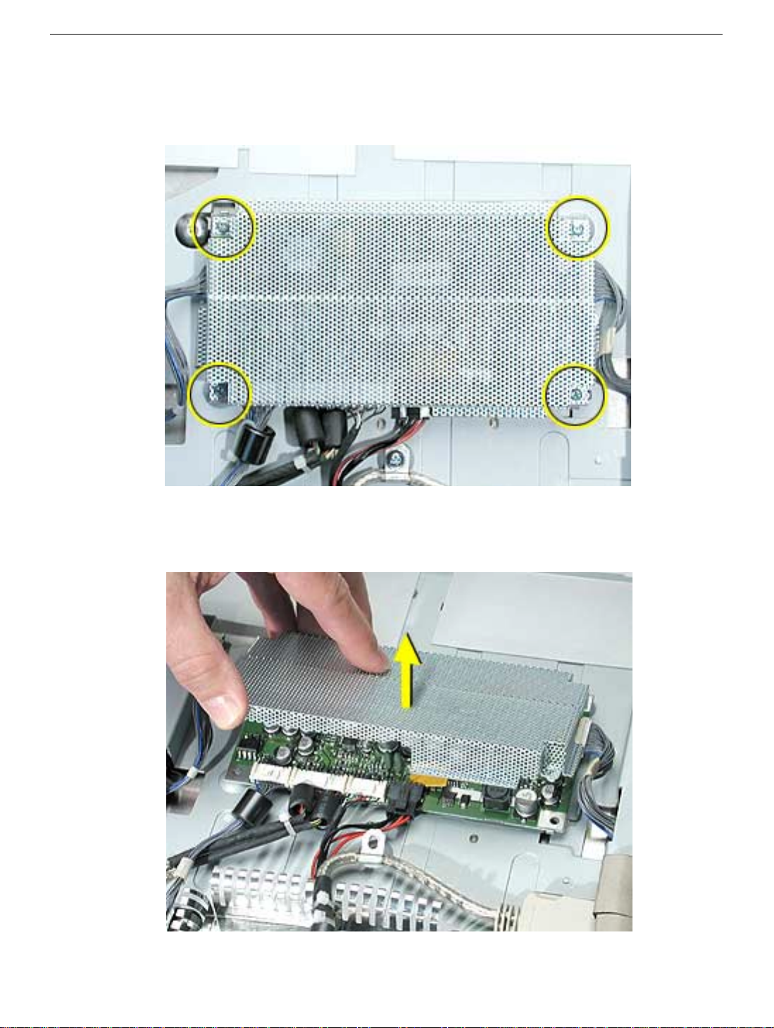
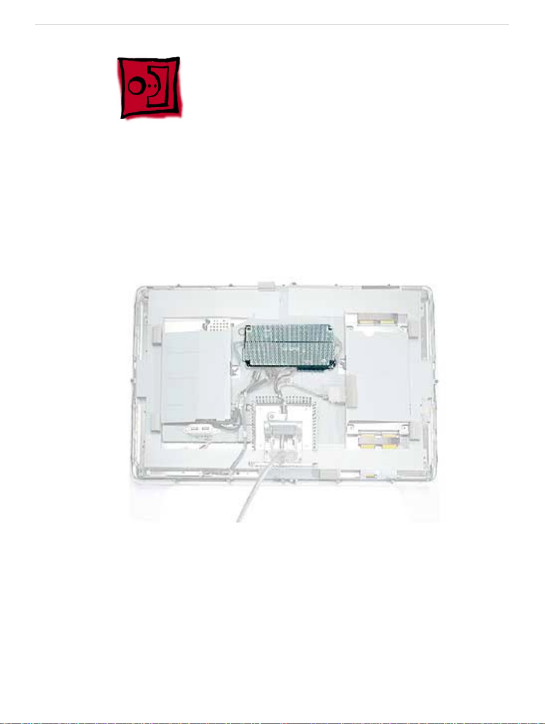
Procedure
1. Remove four screws holding the main board shield.
2. Lift the shield from the main board.
Main Board Shield
Apple Cinema Display 22" (ADC) Take Apart -
9
Page 12
ADC Cable
Tools
This procedure requires the following tools:
• #2 Phillips screwdriver
Part Location
Preliminary Steps
Before you begin, do the following:
• Place the display face down on an ESD mat
• Remove the foot assembly and hinge cover
• Remove the rear cover
• Remove the hinge
• Remove the main board shield
10 -
Apple Cinema Display 22" (ADC) Take Apart
ADC Cable
Page 13

Procedure
1. Remove two screws holding the ADC cable clips.
2. Disconnect the connectors from the ADC cable at the main board and to the display
panel, then remove the ADC cable.
ADC Cable
Apple Cinema Display 22" (ADC) Take Apart -
11
Page 14

USB Cable
Tools
This procedure requires the following tools:
• #2 Phillips screwdriver
Preliminary Steps
Before you begin, do the following:
• Place the display face down on an ESD mat
• Remove the foot assembly and hinge cover
• Remove the rear cover
• Remove the main board shield
Procedure
1. Remove the clear plastic USB cover from the USB socket for transfer to the
replacement cable.
2. Remove the two USB socket screws.
3. Remove the USB cable clip screw.
4. Disconnect the USB cable from the main board, and remove the USB cable.
Note:
When replacing, verify that the USB icon arrows point up.
12 -
Apple Cinema Display 22" (ADC) Take Apart
USB Cable
Page 15

Main Board
Tools
This procedure requires the following tools:
• #2 Phillips screwdriver
Part Location
Main Board
Preliminary Steps
Before you begin, do the following:
• Place the display face down on an ESD mat
• Remove the foot assembly and hinge cover
• Remove the rear cover
• Remove the main board shield
Apple Cinema Display 22" (ADC) Take Apart -
13
Page 16

Procedure
1. Disconnect the six connectors attached to the main board and remove the board.
14 -
Apple Cinema Display 22" (ADC) Take Apart
Main Board
Page 17

Front Bezel
Tools
This procedure requires the following tools:
• #2 Phillips screwdriver
Preliminary Steps
Before you begin, do the following:
• Place the display face down on an ESD mat
• Remove the foot assembly and hinge cover
• Remove the rear cover
Procedure
1. Remove the four bezel screws.
Front Bezel
Apple Cinema Display 22" (ADC) Take Apart -
15
Page 18

2. Lift the panel and chassis assembly off the bezel.
Important:
the bezel.
Note:
remove the items not shown.
The display panel is very heavy. Use caution when lifting the panel out of
The picture below illustrates removal of the display panel, you do not need to
16 -
Apple Cinema Display 22" (ADC) Take Apart
Front Bezel
Page 19

Chassis
Tools
This procedure requires the following tools:
• #2 Phillips screwdriver
Part Location
Chassis
Preliminary Steps
Before you begin, do the following:
• Place the display face down on an ESD mat
• Remove the foot assembly and hinge cover
• Remove the rear cover
• Remove the hinge
• Remove the main board and shield
• Remove the ADC cable and shield
• Remove the USB cable
• Remove the front bezel.
Apple Cinema Display 22" (ADC) Take Apart -
17
Page 20

Procedure
1. Remove the two side screws located at the top and bottom of the display.
2. Remove the four corner screws.
3. Hold the metal chassis on each side and lift it straight up.
18 -
Apple Cinema Display 22" (ADC) Take Apart
Chassis
Page 21

Inverter Board
Tools
This procedure requires the following tools:
• #2 Phillips screwdriver
Preliminary Steps
Before you begin, do the following:
• Place the display face down on an ESD mat
• Remove the foot assembly and hinge cover
• Remove the rear cover
• Remove the front bezel.
• Disconnect the cable connector from the main board to the inverter board
• Disconnect the cable connector from the main board to the display panel
• Disconnect the cable connector from the ADC cable to the display panel
• Remove the chassis from the display panel
Inverter Board
Apple Cinema Display 22" (ADC) Take Apart -
19
Page 22

Procedure
1. Disconnect the backlight bulb wire connectors from the inverter board.
2. Remove the three screws from the inverter shield.
3. The inverter shield has small catches inside that secure the inverter board. Pull back
slightly on the sides of the shield to release the board.
Replacement Note:
shield.
Make sure that the board is secured by the four catches on the
20 -
Apple Cinema Display 22" (ADC) Take Apart
Inverter Board
Page 23

Display Panel
Tools
This procedure requires the following tools:
• #2 Phillips screwdriver
• nylon probe tool (922-5065)
Preliminary Steps
Before you begin, do the following:
• Place the display face down on an ESD mat
• Remove the foot assembly and hinge cover
• Remove the rear cover
• Remove the front bezel.
• Disconnect the cable connector from the main board to the inverter board
• Disconnect the cable connector from the main board to the display panel
• Disconnect the cable connector from the ADC cable to the display panel
• Remove the chassis from the display panel
• Disconnect the backlight bulb wire connectors (top and bottom) from the inverter board
• Remove the inverter board
Display Panel
Apple Cinema Display 22" (ADC) Take Apart -
21
Page 24

Procedure
1. Remove the two screws on the inverter board bracket and remove the bracket.
2. Use the nylon probe tool to carefully spread the securing clip and remove the power/
brightness switch cable.
Replacement Note:
Install the inverter board bracket with the arrow up.
Important:
22 -
Apple Cinema Display 22" (ADC) Take Apart
The backlight bulbs must be returned with the display panel.
Display Panel
Page 25

Top Backlight Bulb
Tools
This procedure requires the following tools:
• jeweler’s #1 Phillips screwdriver
• white cotton gloves (to prevent fingerprints on the bulbs and reflector)
Part Location
Top Backlight Bulb
Preliminary Steps
Before you begin, do the following:
• Place the display face down on an ESD mat
• Remove the foot assembly and hinge cover
• Remove the rear cover
• Remove the front bezel.
Apple Cinema Display 22" (ADC) Take Apart - 23
Page 26

Procedure
1. Peel the gray Mylar tape back on the chassis to expose the backlight bulb wires.
2. Disconnect the two top bulb wire connectors from the inverter board and peel back the
tape to release the wires.
3. Remove the bulb screw.
4. Put on cotton gloves, then carefully slide the bulb tray out of the panel.
Important: The bulbs are very fragile. Handle with care.
Note: The bulbs are interchangeable top and bottom.
24 - Apple Cinema Display 22" (ADC) Take Apart
Top Backlight Bulb
Page 27

Bottom Backlight Bulb
Tools
This procedure requires the following tools:
• jeweler’s #1 Phillips screwdriver
• white cotton gloves (to prevent fingerprints on the bulbs and reflector)
Part Location
Bottom Backlight Bulb
Apple Cinema Display 22" (ADC) Take Apart - 25
Page 28

Preliminary Steps
Before you begin, do the following:
• Place the display face down on an ESD mat
• Remove the foot assembly and hinge cover
• Remove the rear cover
• Remove the front bezel.
• Disconnect the cable connector from the main board to the inverter board
• Disconnect the cable connector from the main board to the display panel
• Disconnect the cable connector from the ADC cable to the display panel
• Remove the chassis from the display panel
26 - Apple Cinema Display 22" (ADC) Take Apart
Bottom Backlight Bulb
Page 29

Procedure
1. Disconnect the two bottom bulb wire connectors from the inverter board and peel back
the tape to release the wires.
2. Remove the bulb screw.
3. Put on cotton gloves, then carefully slide the bulb tray out of the panel.
Important: The bulbs are very fragile. Handle with care.
Note: The bulbs are interchangeable top and bottom
Bottom Backlight Bulb
Apple Cinema Display 22" (ADC) Take Apart - 27
Page 30

Service Source
Troubleshooting
Apple Cinema Display 22" LCD (ADC)
© 2003 Apple Computer, Inc. All rights reserved.
Page 31

Symptom Charts
How to Use the Symptom Charts
The Symptom Charts included in this chapter will help you diagnose specific symptoms
related to the product. Because cures are listed on the charts in the order of most likely
solution, try the cures in the order presented. Verify whether or not the product continues
to exhibit the symptom. If the symptom persists, try the next cure.
Note: If you have replaced a module, reinstall the original module before you proceed to
the next cure.
Note: Referring to the Block Diagram in this manual may be helpful.
Blank screen
This symptom may indicate a problem with the LCD panel, backlight bulbs, inverter, main
board, or related cables or connectors.
1. Check ADC cable. Replace cable if damaged.
2. Check for bent pins in the ADC connector (note, it is normal for two of the pins to be
slightly longer than the others). If pins are slightly bent, carefully straighten. If pins are
severely bent, replace cable. Also, inspect or have the customer inspect the display
port on the computer for broken pin dividers. If the display port is damaged it must be
repaired before inserting the ADC connector.
3. Plug the display into a known-good computer with a known-good video card and ADC
display port. Boot the computer and allow enough time to finish booting.
4. If the power button on the display is flashing, two short flashes then a long flash, in a
delayed repeating pattern, this indicates trouble with either the inverter, backlight
bulbs or related cables or connectors. With this in mind, continue with the
troubleshooting steps to determine the problem.
Symptom Charts
Apple Cinema Display 22" (ADC) Troubleshooting - 1
Page 32

5. To check whether the LCD is working, make sure that the display’s power light is on
(glows white). Shine a bright light such as sunlight or a high intensity lamp (see
Important note, below) into the screen and at the same time notice whether you can
see faint images of desktop items on the screen.
• If desktop items can be seen, the LCD panel is working. The problem may be with
the inverter or backlight bulbs or related cables or connectors. Continue with the
troubleshooting steps.
• If no desktop items can be seen, the problem may be with the LCD panel or the
main board or related cables or connectors.
Important: Lights get very hot and can quickly damage the display; be extremely
careful not to allow too much heat next to the screen or other parts of the display and
do not allow the light fixture to touch the screen, or damage can result.
6. Warning: The inverter board generates high voltage when the display is plugged
in. Do not touch the inverter board components, pins or connectors, when the
display is connected to the computer.
Disconnect the display from the computer, then open the display and check for
secure connections at J2, J5, J6, J4, J3 and the ADC cable connection to the panel.
Note: Refer to the Block Diagram in this manual for connector locations.
7. Plug the display into a known-good computer, then boot the computer.
8. Verify +24-28V at pin 1 of J4. If not, replace ADC cable.
9. Verify +15V at pin 1 of J2. If not, replace the main board.
10. Verify +5V at pin 1 of J5. If not, replace the main board.
2 - Apple Cinema Display 22" (ADC) Troubleshooting
Symptom Charts
Page 33

Partially dim screen
This symptom indicates a problem with the inverter or backlight bulbs (on the side of the
display that is dim), or related cables or connectors. This may be caused by the backlight
bulbs or the inverter not working properly.
1. Plug the display into a known-good computer with a known-good video card and ADC
display port. Boot the computer.
2. Notice whether the power button on the display is flashing, two short flashes then a
long flash, in a delayed repeating pattern. This indicates trouble with either the
inverter, backlight bulbs or related cables or connectors (this indicator may not always
be exhibited). With this in mind, continue with the troubleshooting steps to determine
the problem.
3. Warning: The inverter board generates high voltage when the display is plugged
in. Do not touch the inverter board components, pins or connectors, when the
display is connected to the computer.
Disconnect the display from the computer, then open the display and check for
secure connections where the backlight bulbs plug into the inverter.
Note: Refer to the Block Diagram in this manual for connector locations.
4. Important: The backlight bulbs are extremely delicate. Handle with care.
To determine whether the problem is with the backlight bulbs or the inverter board,
disconnect the two CN connectors to the backlight bulbs on the side that is dim.
Connect the CN connectors to a known good backlight bulb tray (the bulb tray from
the other side of the display can be removed and plugged in to test, if known good).
Connect the display’s ADC connector to a known-good computer, then boot the
computer. If one or more of the bulbs does not light, replace the inverter. If the bulbs
light correctly, the original backlight bulb tray is bad, replace the bulb tray.
Note: The top and bottom backlight bulb trays are interchangeable. The bulb trays
are not specific to the top or bottom.
Symptom Charts
Apple Cinema Display 22" (ADC) Troubleshooting - 3
Page 34

USB device not working
1. Check for bent pins in the ADC connector (note, it is normal for two of the pins to be
slightly longer than the others). If pins are slightly bent, carefully straighten. If pins are
severely bent, replace cable. Also, inspect or have the customer inspect the display
port on the computer for broken pin dividers. If the display port is damaged it must be
repaired before inserting the ADC connector.
2. Plug the display into a computer with a known-good ADC display port, then boot the
computer. On the back of the display, connect a known-good USB device into one of
the USB ports, then check Apple System Profiler to see if it is recognized. Check both
USB ports.
Note: x+R, refreshes the Apple System Profiler list when USB devices are changed.
• If the device is recognized, the customer’s USB device may be the issue.
• If not, check the J1 USB connections and cables. If not that, replace the main
board.
Power/brightness switch not working
1. Check J5 connection and verify that the cable is connected to the power/brightness
switch cable connector.
2. Replace the rear cover (includes power/brightness switch board).
Note: The power/brightness switch board is permanently attached to the rear cover.
3. Replace main board.
4 - Apple Cinema Display 22" (ADC) Troubleshooting
Symptom Charts
Page 35

When displaying a single color over the screen ar ea, the LCD panel shows one
or more pixels that are not properly lit
Active-matrix LCD technology uses rows and columns of addressable locations (pixels)
that render text and images on screen. Each pixel location has three separate subpixels
(red, green, and blue) that allow the image to be rendered in full color. Each subpixel has a
corresponding transistor responsible for turning the subpixel on or off.
There are typically millions of these subpixels on an LCD display. For example, the LCD
panel used in the Apple Cinema HD display is made up of 2.3 million pixels and 6.9 million
red, green, and blue subpixels. Occasionally, a transistor does not work perfectly, which
may result in the affected subpixel being turned on (bright) or turned off (dark). With the
millions of subpixels on a display, it is quite possible to have a low number of faulty
transistors on an LCD. Therefore, a certain number of subpixel anomalies is considered
acceptable. Rejecting all but perfect LCD panels would significantly increase the retail
price for products using LCD displays. These factors apply to all manufacturers using LCD
technology—not just Apple products.
To determine whether or not the display has an acceptable number of pixel anomalies,
follow the steps below:
1. Set the display image to one of the following colors: all-white display, all-red display,
all-green display, or all-blue display.
Note: Knowledge Base article 112125: Service Diagnostics Matrix, has the LCD
Tester Diagnostic Utility that will generate these patterns on the screen.
2. Using a jeweler’s loupe, pocket microscope, or other magnifying device, identify and
count each subpixel anomaly:
• Bright subpixel anomaly = subpixel that is always on
• Dark subpixel anomaly = subpixel that is always off
3. Important: Check the number of subpixel anomalies with the following chart:
Acceptable Number of Subpixel
Anomalies
Replace the Display
Bright Dark Combination Bright Dark Combination
up to 8 up to10 up to 15 8 or more 11 or more 16 or more
4. If the number of subpixel anomalies exceeds the acceptable number listed in the
chart, replace the display panel.
5. If the number of subpixel anomalies is acceptable, explain to the customer that the
pixel anomalies are within specifications, and no repair is necessary.
Important: Do not release the specifications to customers. Instead, inform them that
a certain number of subpixel anomalies is considered acceptable, and these factors
apply to all manufacturers using LCD technology—not just Apple products.
Symptom Charts
Apple Cinema Display 22" (ADC) Troubleshooting - 5
Page 36

Service Source
Views
Apple Cinema Display 22" LCD (ADC)
© 2003 Apple Computer, Inc. All rights reserved.
Page 37

Block Diagram
Block Diagram
Backlight Bulb
Connectors
Inverter
Board
Backlight Bulb
Connectors
Power/Brightness
Switch Board
J2
J5
Main Board
USB Socket
ADC Cable
J3
J4J1 J6
Panel Signal Input
LCD Display Panel
Block Diagram
Apple Cinema Display 22" (ADC) Views - 1
Page 38

Exploded View
Exploded View
Hinge Cover 922-3945
Main Board Shield 922-5673
Foot 922-3941
Rear Cover 922-5666 (includes
power/brightness switch board)
Hinge 922-5670
USB Cover 922-5674
Main Board 661-2810
Chassis 922-5667
Inverter Shield 922-5671
Inverter Board 661-2809
LCD Display Assembly
661-2801
ADC Cable Assembly
922-5669
USB Cable Assembly
922-5677
Backlight Bulb Assembly
922-5675
Front Bezel Assembly
922-5668
2 - Apple Cinema Display 22" (ADC) Views
Exploded View
Page 39

Screw Matrix
13 mm Hex 922-5679 Foot (3)
Screw Matrix
10 mm Hex 922-5680 Rear Cover (18)
10 mm Phillips (black) 922-3541 Chassis to Bezel (4)
8 mm Phillips (flat head) 922-5681 Chassis sides (2)
10 mm Phillips (washer) 922-5682 Chassis corners (4)
6 mm Phillips 922-5135 Main board shield (4)
5 mm Phillips (flat head) 922-5640 USB socket (2)
8 mm Phillips (lock washer) 922-5683 ADC cable clips (2)
6 mm Phillips (yellow, lockhead) 922-5684 USB cable clip (1)
10 mm Phillips (yellow, lockhead) 922-5641 ADC cable bracket (2)
6 mm Phillips 922-5685 Hinge to chassis (4)
4 mm Phillips 922-5605 Inverter board shield (3)
5 mm Phillips 922-5686 Inverter board bracket (2)
Screw Matrix
Apple Cinema Display 22" (ADC)
 Loading...