

Page 1
K
Service Source
Apple AudioVision 14
Display
Page 2
K
Service Source
Basics
Apple AudioVision 14 Display
Page 3

Basics Self-Threading Screws - 1
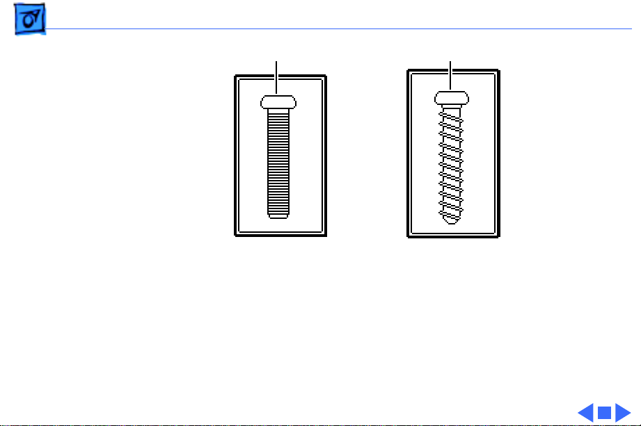
Self-Threading Screws
Caution:
damage the AudioVision 14 Display. Thread the screws
properly and do not overtighten them.
The AudioVision 14 Display uses both machine screws and
self-threading screws. Be aware of the following guidelines
when you are replacing a self-threading screw:
• Never overtighten self-threading screws.
• Before tightening a self-threading screw, back the screw
Improperly installed self-threading screws could
off slightly to be sure it is threaded properly.
Page 4
Basics Self-Threading Screws - 2
Machine Screw
Self-Threading Screw
Page 5
K
Service Source
Specifications
Apple AudioVision 14 Display
Page 6

Specifications Characteristics - 1
Characteristics
Picture Tube
Screen Resolution
Scan Rates
Active V ideo Display Area
14-inch diagonal, 13-inch viewable screen
Trinitron CRT
.26-mm pitch aperture grille
640x480
Horizontal scan rate: 35.0 kHz
Vertical refresh rate: 66.7 Hz
9.3 in. by 6.9 in.
(235 mm by 176 mm)
Page 7

Specifications Characteristics - 2
Video Input Signals
Audio Input Signals
Microphone
Speakers
Red, green, and blue video signals;.714 V peak to peak; white
positive
Composite synchronization, negative-going TTL
Accepts audio signal of up to 6 Vpp (line level—low sensitivity) or
as low as 20 mVpp (microphone level—high sensitivity)
without clipping the signal, depending upon the level and
sensitivity setting
Directional, optimized for use in speech recognition and other
voice-related applications
Stereo, with ported (base reflex) chamber design
Minimum loudness: 90 dB SPL at 1 kHz at 0.5 m
Frequency response: 100 Hz–15 kHz ± 3dB
Page 8

Specifications Characteristics - 3
Headphone Jack
Output level: 1.75 Vpp into 4 ohm load and 2 Vpp into 10 k ohm
load
Page 9

Specifications Controls - 4
Controls
User Controls
Front Keypad: Contrast, brightness, and volume keys; mute
button; microphone button
Back panel: On/off switch
Page 10

Specifications Electrical - 5
Electrical
Voltage
Frequency
Power
100–240 VAC ± 10%
50–60 Hz ± 3%
55 W maximum, all line conditions
The monitor contains internal power-line fuse protection.
This fuse should be replaced with the same type by a qualified
service technician.
Page 11

Specifications Physical - 6
Physical
Size
Weight
W arm-Up Time
Height: 13 in. (330 mm)
Width: 13.5 in. (344 mm)
Depth: 15.5 in. (394 mm)
33 lb. (15 kg)
20 minutes required to meet all specifications
Page 12

Specifications Environmental - 7
Environmental
Operating Temperature
Relative Humidity
50–104°F (10–40°C)
90% maximum, noncondensing
Page 13

K
Service Source
Troubleshooting
Apple AudioVision 14 Display
Page 14

Troubleshooting General - 1
General
The Symptom Charts included in this chapter will help you
diagnose specific symptoms related to your product. Because cures
are listed on the charts in the order of most likely solution, try
the first cure first. Verify whether or not the product continues to
exhibit the symptom. If the symptom persists, try the next cure.
(Note: If you have replaced a module, reinstall the original module
before you proceed to the next cure.)
If you are not sure what the problem is, or if the Symptom Charts
do not resolve the problem, refer to the Flowchart for the product
family.
For additional assistance, contact Apple Technical Support.
Page 15

Troubleshooting Symptom Charts/No Raster - 2
Symptom Charts
No Raster
No raster, LED off 1 Ensure monitor’s video cable is connected to the computer or
the video card in the computer.
2 Check power cable connections and power switch.
3 Check all connections on main board.
4 Replace blown fuse.
5 Replace main board.
No raster, LED on,
CRT filament on
1 Ensure monitor’s video cable is connected to the computer or
the video card in the computer.
2 Adjust contrast and brightness knobs.
3 Connect known-good monitor and verify that built-in video
signal or video card is working properly.
4 Check all connections on main board. Make sure video
connector is secure and wires are inside plastic connector.
5 Perform video adjustments. Refer to “Video” in Adjustments
chapter.
6 Replace main board.
7 Replace CRT.
Page 16

Troubleshooting Symptom Charts/Geometry - 3
Geometry
Raster too short, tall,
narrow, or wide
Raster not centered 1 Move unit away from monitors, fluorescent lights, or other
Horizontal linearity
bad (size of text
differs at sides of
screen)
1 Adjust vertical or horizontal size controls. Refer to
“Geometry” in Adjustments chapter.
2 Replace main board.
electrical equipment.
2 Adjust vertical or horizontal center controls. Refer to
“Geometry” in Adjustments chapter.
3 Replace main board.
Replace main board.
Page 17

Troubleshooting Symptom Charts/Geometry
(Continued) - 4
Vertical linearity bad
(size of text differs at
top vs. bottom of
screen)
Abnormal or
distorted raster
Geometry
Replace main board.
1 Move unit away from monitors, fluorescent lights, or other
electrical equipment.
2 Perform geometry adjustments. Refer to “Geometry” in
Adjustments chapter.
3 Replace main board.
4 Replace CRT (rarely required).
(Continued)
Page 18

Troubleshooting Symptom Charts/Geometry
(Continued)
- 5
Geometry
Entire raster is tilted 1 Move unit away from monitors, fluorescent lights, or other
electrical equipment.
2 Perform geometry adjustments. Refer to “Geometry” in
Adjustments chapter.
3 Perform geometric distortion adjustments. Refer to
“Geometric Distortion” in Adjustments chapter.
4 Replace main board.
(Continued)
Page 19

Troubleshooting Symptom Charts/Synchronization - 6
Synchronization
Picture breaks into
diagonal lines
Picture rolls
vertically
Picture breaks and
rolls horizontally
1 Connect known-good monitor and verify that built-in video
signal or video card is working properly.
2 Replace main board.
1 Connect known-good monitor and verify that built-in video
signal or video card is working properly.
2 Replace main board.
1 Connect known-good monitor and verify that built-in video
signal or video card is working properly.
2 Replace main board.
Page 20

Troubleshooting Symptom Charts/Synchronization
(Continued)
- 7
Black raster with
single vertical or
horizontal line
Synchronization
1 Replace main board.
2 Replace CRT.
(Continued)
Page 21

Troubleshooting Symptom Charts/Video - 8
Video
Raster too dark, too
bright, or washed out
Out of focus 1 Perform focus adjustment. Refer to “Video” in Adjustments
1 Adjust external contrast and brightness controls.
2 Connect known-good monitor and verify that built-in video
signal or video card is working properly.
3 Perform video adjustments. Refer to “Video” in Adjustments
chapter.
4 Replace main board.
5 Replace CRT (rarely required).
chapter.
2 Replace main board.
3 Adjust focus controls to their limits. If bad focus remains on
one part of display, replace CRT.
Page 22

Troubleshooting Symptom Charts/Video
(Continued)
- 9
Predominant color
tint
Out of convergence
(color bleeding out
from text or lines)
Video
1 Check video card in computer.
2 Perform video adjustments. Refer to “Video” in Adjustments
3 Replace main board.
4 Replace CRT (if you cannot eliminate red, green, or blue
1 Connect known-good monitor and verify that built-in video
2 Perform convergence adjustments. Refer to “Video” in
3 Replace main board.
4 Replace CRT.
(Continued)
chapter.
tint).
signal or video card is working properly.
Adjustments chapter.
Page 23

Troubleshooting Symptom Charts/Audio - 10
Audio
Sound comes out of
only one speaker
Internal microphone
doesn’t record
No sound or volume is
too low
One of sound output options may be set to Stereo when your
computer is only capable of Mono sound output.
1 To turn on microphone, press microphone button on keypad.
Microphone-on LED lights up when microphone is on.
2 Make sure that monitor is selected as sound input and
playback source.
1 Verify that external sound sources are securely connected to
monitor’s sound-out port.
2 Press volume key on keypad.
3 Press mute button to turn mute off.
4 Press microphone button to turn microphone off.
Page 24

Troubleshooting Symptom Charts/Miscellaneous - 11
Miscellaneous
Picture jitters or
flashes
Intermittently shuts
down
Flashing or wavy
screen
Black screen spots
(burnt phosphor)
1 Move unit away from monitors, fluorescent lights, or other
electrical equipment.
2 Check that all ground cables are secure.
3 Replace main board.
Replace main board.
Replace main board.
Replace CRT.
Page 25

Troubleshooting Symptom Charts/Miscellaneous
(Continued)
- 12
Miscellaneous
Monitor emits highpitched noise
Does not degauss Replace main board.
Erratic or no
communication with
ADB device
Moving and clicking a
Logitech mouse has no
effect on screen, but
keyboard input is
accepted
Replace main board.
Replace keyboard cable, keyboard, mouse, or other ADB device.
Some models of Logitech mice are incompatible with this display.
Refer customers to Logitech for information on mouse
compatibility and upgrades. The display is not at fault; do not
replace it.
(Continued)
Page 26

Troubleshooting Symptom Charts/Miscellaneous
(Continued)
- 13
Thin horizontal line
on screen
Miscellaneous
Displays smaller than 15 inches with tron-style CRTs typically
have a single horizontal grid wire about one-third of the way from
the bottom of the display image. This supporting wire, which is
thinner than a human hair, stabilizes the aperture grill against
shocks. The line is common to all tron-style displays and is not a
screen defect. It cannot be adjusted out or eliminated by repairing
or replacing display modules.
(Continued)
Page 27

K
Service Source
T ak e Apart
Apple AudioVision 14 Display
Page 28
Take Apart Rear Cover - 1
Rear Cover
Rear Cover
No preliminary steps are
r equired before you begin
this procedure.
1 With the monitor face-
down on a protective pad,
swivel the monitor
stand to access the two
rear cover screws.
2 Using a T-15 torx
driver, remove the
screws.
Page 29
Take Apart Rear Cover - 2
Bezel
Rear Cover
Microphone
Locking Tab
Pull-Apart Tool
Locking Tab
3 Move the monitor so
that the microphone is
toward you.
4
Note:
The locking tabs
are located 1.5 inches in
from the sides of the
rear cover.
Press down on the
locking tabs. Using the
pull-apart tool, pry
apart the sides of the
rear cover.
Page 30
Take Apart Rear Cover - 3
5 Lift off the rear cover.
Rear
Cover
Groove
Guide
Replacement Note:
Line
up the rear cover
grooves with the base
assembly guides and
slide on the rear cover.
Page 31

Take Apart Audio Enclosure & Speakers - 4
Audio Enclosure & Speakers
Before you begin,
• Remove the rear cover
• Discharge the CRT
• Remove the anode cap
±
Warning:
contains high voltage and a
high-vacuum picture tube.
To prevent serious injury,
review CRT safety in
Bulletins/Safety.
Audio Enclosure
This product
Page 32

Take Apart Audio Enclosure & Speakers - 5
±
Tie Wrap
Degauss Panel
Ground Cable
Warning:
grounding wriststrap until
after discharging the CRT.
1 Cut the tie wrap from
the yoke and two ground
cables.
2 Disconnect the two
ground cables from the
degauss panels.
3 Disconnect the 4-pin,
4-wire CRT cable from
connector BD1.
Never use a
BD1
Ground Cable
Page 33

Take Apart Audio Enclosure & Speakers - 6
Video Board Assembly
Caution:
Twisting,
4
bending, or applying
force to the video board
assembly could damage
the neck of the CRT. Be
sure to pull the video
board assembly straight
off the CRT.
Cable Tie
BP2
Pull the video board
assembly straight off the
neck of the CRT.
5 Cut the tie wrap that
connects cables BP2 and
BP3.
6 Undo the cable tie that
connects cables BP2 and
BP4.
Page 34

Take Apart Audio Enclosure & Speakers - 7
Cable Tie
BP2
Video Board Assembly
7 D isconnect the degauss
cable from connector
BP2.
Page 35

Take Apart Audio Enclosure & Speakers - 8
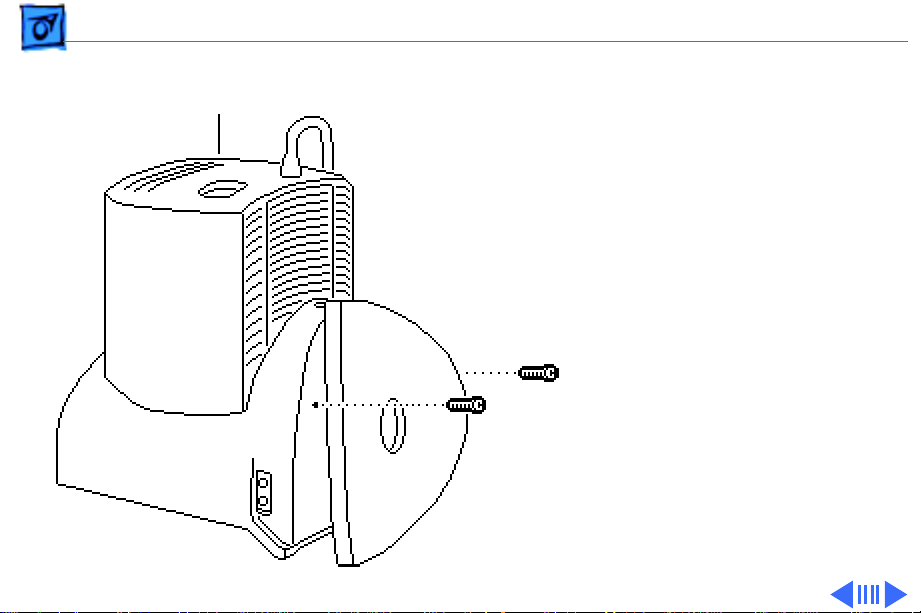
8 Using a T-15 torx
Bezel
driver, remove the four
self-threading screws
that secure the base
assembly to the bezel.
Base Assembly
Replacement Caution:
Do not overtighten the
four self-threading
screws. See Basics
section for more
information regarding
self-threading screws.
Page 36

Take Apart Audio Enclosure & Speakers - 9
CRT Assembly
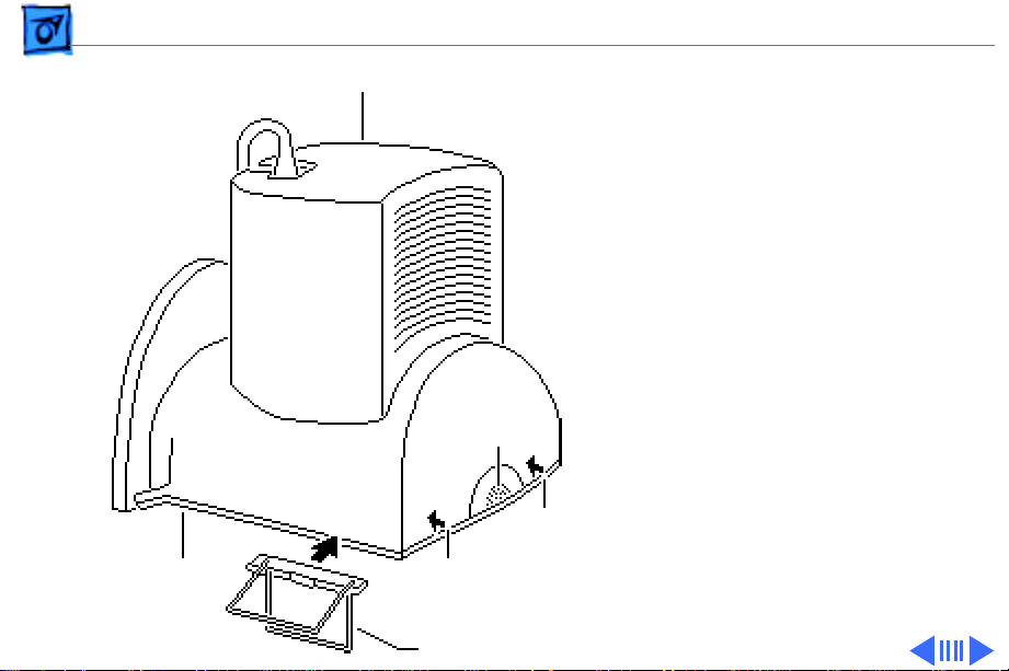
Caution:
assembly is connected to
The CRT
9
the base by LED and
microphone cables. Be
careful not to tear these
cables when separating
the CRT from the base
assembly.
Lift the CRT assembly off
the base and place it
face-down on a
protective workbench
pad.
Base Assembly
LED Assembly
Page 37

Take Apart Audio Enclosure & Speakers - 10
10
Note:
Perform this step
if you are replacing the
speakers only.
Using a T-15 torx
Audio Enclosure
driver, remove the
eight self-threading
screws that secure the
speakers to the audio
enclosure.
11 Disconnect both speaker
cables.
12 Remove the speakers.
Speakers
Page 38

Take Apart Audio Enclosure & Speakers - 11
Replacement Caution:
Do not overtighten the
self-threading screws.
See Basics section for
more information
regarding self-threading
screws.
Page 39

Take Apart Audio Enclosure & Speakers - 12
13 Using a jeweler’s
Audio Board
screwdriver, release the
latches and disconnect
these cables from the
B5
B8
B3
B10
B4
audio board:
• Microphone cable
from B5
• Front panel controls
and LEDs cable from
B3
• Video cable from B4
• Video cable from B10
• Four-wire cable from
B8
14 Undo the cable tie that
connects the video cable
to the audio enclosure.
Page 40

Take Apart Audio Enclosure & Speakers - 13
HP6
HP5
Main Board
Tie Wrap
BP5
BV4
15 Cut the tie wrap that
secures the cables to
connectors BP5, BV4,
HP5, and HP6.
16 Disconnect the audio
ground cables from
connectors HP5 and HP6
on the main board.
Page 41

Take Apart Audio Enclosure & Speakers - 14
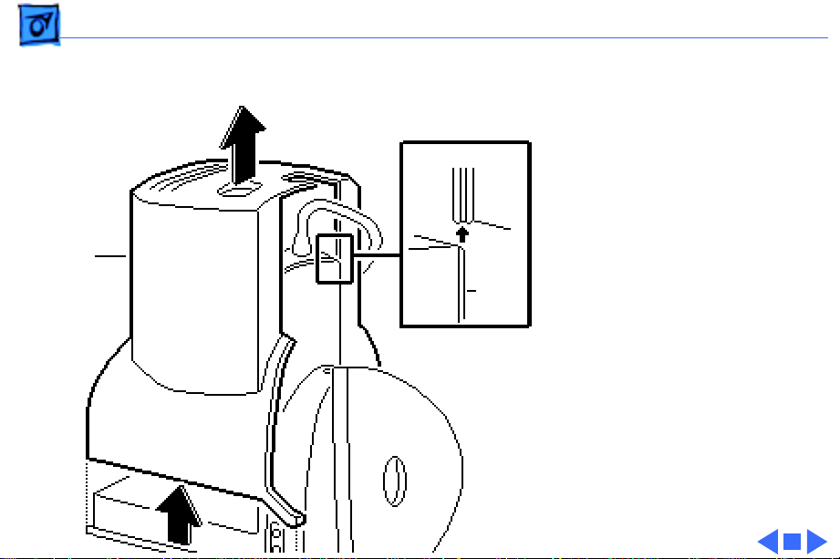
Audio Enclosure
Inner Guide
Base Assembly
17 Using a flat-blade
screwdriver, loosen the
two screws that secure
the base assembly to the
audio enclosure.
18 Using pliers, pull out
the two screws.
19 Slide out and remove the
audio enclosure
assembly.
Page 42

Take Apart Video Cable & Strain Relief - 15
Video Cable & Strain Relief
Before you begin,
• Remove the rear cover
• Discharge CRT
• Remove the anode cap
• Remove the audio
enclosure & speakers
±
Warning:
contains high voltage and a
high-vacuum picture tube.
To prevent serious injury,
review CRT safety in
Bulletins/Safety.
Video Cable
This product
Page 43

Take Apart Video Cable & Strain Relief - 16
±
Main Board
Warning:
grounding wriststrap until
after discharging the CRT.
1 Remove the screw that
secures the video cable
to the EMI shield on the
main board.
2 Remove the video cable
from connector BV1.
Video Cable
Never use a
Page 44

Take Apart Video Cable & Strain Relief - 17
Base Assembly
Strain Relief Plate
Video Cable
3 Press in the two tabs to
release the strain relief
plate from the base
assembly.
4 Lift and remove the
strain relief plate with
the attached video cables
off the base assembly.
5 Remove the video cable
from the strain relief
plate.
Replacement Note:
Be
sure to secure the video
cable onto the strain
relief plate before you
replace the strain relief
plate.
Page 45

Take Apart Main Board - 18
Main Board
Before you begin,
• Remove the rear cover
• Discharge CRT
• Remove the anode cap
• Remove the audio
enclosure & speakers
• Remove the video cable
±
Main Board
Warning:
contains high voltage and a
high-vacuum picture tube.
To prevent serious injury,
review CRT safety in
Bulletins/Safety.
This product
Page 46

Take Apart Main Board - 19
±
Base Assembly
Main Board
Warning:
grounding wriststrap until
after discharging the CRT.
1 Remove the two
mounting screws that
secure the main board to
the base assembly.
Never use a
Page 47

Take Apart Main Board - 20
2 Press the release latches
BV4
BP5
and disconnect the
following cables from
the main board:
• Two-pin, 2-wire on/
off switch cable from
connector BP3
• Two-pin, 2-wire on/
off switch cable from
connector BP4
• Two-pin, 2-wire
audio cable from
connector BP5
• Four-pin, 4-wire
audio cable from
connector BV4
BP3 BP4
Main Board
Page 48

Take Apart Main Board - 21
3 Push out on the two rear
release latches and lift
the main board slightly.
4 Push out the two front
release latches. Lift up
and slide the main board
back to clear the
mounting tabs.
5 Remove the main board
from the assembly.
Replacement Note:
the board under the
mounting tabs before you
snap the latches into
place.
Slide
Page 49

Take Apart Main Board - 22
Replacement Note:
the cutoff adjustment
whenever you replace the
main board. See “Video” in
the adjustments chapter.
Perform
Page 50

Take Apart On/Off Switch Assembly - 23
On/Off Switch Assembly
Before you begin,
• Remove the rear cover
• Discharge the CRT
• Remove the anode cap
• Remove the audio
enclosure & speakers
• Remove the video cable
• Remove the main board
±
Warning:
contains high voltage and a
high-vacuum picture tube.
To prevent serious injury,
review CRT safety in
Bulletins/Safety.
On/Off Switch Assembly
This product
Page 51

Take Apart On/Off Switch Assembly - 24
±
Clip
Base
Assembly
On/Off Switch Assembly
Warning:
grounding wriststrap until
after discharging the CRT.
1 Lift the clip and remove
the on/off switch
assembly from the base
assembly.
Never use a
Page 52

Take Apart Monitor Stand - 25
Monitor Stand
Before you begin,
• Remove the rear cover
• Discharge the CRT
• Remove the anode cap
• Remove the audio
enclosure & speakers
• Remove the video cable
• Remove the main board
• Remove the on/off switch
assembly
Monitor Stand
Page 53

Take Apart Monitor Stand - 26
±
Latch
Monitor Stand
Latch
Base Assembly
Monitor Stand
Support
Warning:
contains high voltage and a
high-vacuum picture tube.
To prevent serious injury,
review CRT safety in
Bulletins/Safety.
±
Warning:
grounding wriststrap until
after discharging the CRT.
1 Swivel the base
assembly to align the
monitor stand support
latches with the opening
of the base assembly.
Press down on the two
monitor stand support
latches.
This product
Never use a
Page 54

Take Apart Monitor Stand - 27
Latch
Monitor Stand
Latch
Base Assembly
Monitor Stand
Support
2 Hold up the base
assembly and monitor
stand. Press down on the
two monitor stand
support latches and pull
off the monitor stand
support.
3 Turn the base assembly
and remove the monitor
stand.
Page 55

Take Apart Base Assembly - 28
Base Assembly
Before you begin,
• Remove the rear cover
• Discharge the CRT
• Remove the anode cap
• Remove the audio
enclosure & speakers
• Remove the video cable
• Remove the main board
• Remove the on/off switch
assembly
• Remove the monitor stand
Base Assembly
Page 56

Take Apart Base Assembly - 29
±
Warning:
contains high voltage and a
high-vacuum picture tube.
To prevent serious injury,
review CRT safety in
Bulletins/Safety.
±
Warning:
grounding wriststrap until
after discharging the CRT.
Complete all the steps on the
previous page.
This product
Never use a
Page 57

Take Apart Front Panel Controls & LEDs - 30
Front Panel Controls & LEDs
Before you begin,
• Remove the rear cover
• Discharge the CRT
• Remove the anode cap
±
Warning:
contains high voltage and a
high-vacuum picture tube.
To prevent serious injury,
review CRT safety in
Bulletins/Safety.
Front Panel Controls & LEDs
This product
Page 58

Take Apart Front Panel Controls & LEDs - 31
±
BD1
Degauss Panel
Ground Cable
Ground Cable
Warning:
grounding wriststrap until
after discharging the CRT.
1 Cut the tie wrap and
disconnect the two
ground cables from the
degauss panels and the
4-pin, 4-wire CRT
cable from connector
BD1.
Never use a
Page 59

Take Apart Front Panel Controls & LEDs - 32
Video Board Assembly
Caution:
bending, or applying
Twisting,
2
force to the video board
assembly could damage
the neck of the CRT. Be
sure to pull the video
board assembly straight
off the CRT.
Remove the video board
Cable Tie
assembly from the neck
of the CRT.
3 Cut the tie wrap that
connects cables BP2 and
BP3.
4 Undo the cable tie that
connects cables BP2 and
BP2
BP4.
Page 60

Take Apart Front Panel Controls & LEDs - 33
Cable Tie
BP2
Video Board Assembly
5 Disconnect the degauss
cable from connector
BP2.
Page 61

Take Apart Front Panel Controls & LEDs - 34
6 Remove the four screws
Bezel
that secure the base
assembly to the bezel.
Base Assembly
Replacement Caution:
Do not overtighten the
four screws.
Page 62

Take Apart Front Panel Controls & LEDs - 35
7 Carefully lower the
front of the monitor
CRT Assembly
until it lies face-down
on the workbench.
Bezel
Base Assembly
Page 63

Take Apart Front Panel Controls & LEDs - 36
8 Disconnect the cable
from connector B3 on
the audio enclosure
board.
9 Using a T-10 torx
Front Panel
Controls Board
Audio
Enclosure Board
Audio Board
B3
driver, remove the two
screws that secure the
front panel controls
board to the bezel.
Page 64

Take Apart Front Panel Controls & LEDs - 37
10 Remove the front panel
controls board.
Front Panel
Controls Board
Audio
Enclosure Board
Page 65

Take Apart CRT Assembly - 38
CRT Assembly
Before you begin,
• Remove the rear cover
CRT Assembly
• Discharge the CRT
• Remove the anode cap
±Warning: This product
contains high voltage and a
high-vacuum picture tube.
To prevent serious injury,
review CRT safety in
Bulletins/Safety.
±Warning: Never use a
grounding wriststrap until
after discharging the CRT.
Page 66

Take Apart CRT Assembly - 39
1 Cut the tie wrap and
Degauss
Panel
Two-Wire
Connector
disconnect the two
ground cables from the
degauss panels and the
4-pin, 4-wire CRT
cable from connector
BD1.
2 Disconnect the two-
wire (black/white)
Ground
Cable
Ground Cable
BD1
cable.
Page 67

Take Apart CRT Assembly - 40
Cable Tie
BP2
Video Board Assembly
3 Caution: Twisting,
bending, or applying
force to the video board
assembly could damage
the neck of the CRT. Be
sure to pull the video
board assembly straight
off the CRT.
Remove the video board
assembly from the neck
of the CRT.
4 Cut the tie wrap that
connects cables BP2 and
BP3.
5 Undo the cable tie that
connects cables BP2 and
BP4.
Page 68

Take Apart CRT Assembly - 41
Cable Tie
BP2
Video Board Assembly
6 Disconnect the degauss
cable from connector
BP2.
Page 69

Take Apart CRT Assembly - 42
7 Remove the four screws
Bezel
that secure the base
assembly to the bezel.
Base Assembly
Page 70

Take Apart CRT Assembly - 43
8 Carefully lower the
front of the monitor
CRT Assembly
until it lies face-down
on the workbench.
Bezel
Base Assembly
Page 71

Take Apart CRT Assembly - 44
Microphone Assembly Clip
Bezel
Tab
Bezel
CRT
Assembly
Degauss
Panel
9 Remove the four self-
threading bolts that
secure the degauss
panels and CRT to the
bezel.
10 Push the top degauss
panel towards the CRT
and release the
microphone assembly
clip.
11 Remove the degauss
panels.
Page 72

Take Apart CRT Assembly - 45
Replacement Note:
CRT Assembly
When replacing the top
degauss panel, make sure
the microphone
assembly clip is attached
to the panel and the two
bezel tabs are inserted
into the holes.
12 Carefully lift the CRT
Washer
assembly out of the
bezel.
Replacement Note:
Replace the washers
between the CRT and the
bezel if they are damaged
or missing.
Bezel
Page 73

Take Apart Microphone Assembly - 46
Microphone Assembly
Microphone
Assembly
Before you begin,
• Remove the rear cover
• Discharge the CRT
• Remove the anode cap
• Remove the CRT assembly
±Warning: This product
contains high voltage and a
high-vacuum picture tube.
To prevent serious injury,
review CRT safety in
Bulletins/Safety.
Page 74

Take Apart Microphone Assembly - 47
B5
Audio Board
±Warning: Never use a
grounding wriststrap until
after discharging the CRT.
1 Disconnect the
microphone cable from
connector B5 on the
audio board.
Page 75

Take Apart Microphone Assembly - 48
2 Remove the microphone
cable from its guides
along the bezel.
Bezel
Microphone Assembly
3 Using a T-20 torx
driver, remove the two
screws that secure the
microphone assembly to
the bezel.
4 Remove the microphone
assembly.
Page 76

Take Apart Microphone Assembly - 49
Bezel
Microphone Assembly
Replacement Caution:
When reattaching the
bezel to the base
assembly, be careful not
to pinch the microphone
assembly cable.
Page 77

Take Apart Bezel - 50
Bezel
Bezel
Before you begin,
• Remove the rear cover
• Discharge the CRT
• Remove the anode cap
• Remove the front panel
controls & LEDs
• Remove the CRT assembly
• Remove the microphone
assembly
±Warning: This product
contains high voltage and a
high-vacuum picture tube.
To prevent serious injury,
review CRT safety in
Bulletins/Safety.
Page 78

Take Apart Bezel - 51
±Warning: Never use a
CRT
Washer
Bezel
grounding wriststrap until
after discharging the CRT.
Complete all the steps on the
previous page.
Replacement Note: Install
the four washers included
with the new bezel.
Page 79

Take Apart Fuse - 52
Fuse
Before you begin,
• Remove the rear cover
• Discharge the CRT
• Remove the anode cap
±Warning: This product
contains high voltage and a
high-vacuum picture tube.
To prevent serious injury,
review CRT safety in
Bulletins/Safety.
±Warning: Never use a
grounding wriststrap until
after discharging the CRT.
Fuse
Page 80

Take Apart Fuse - 53
Using a small, longstemmed screwdriver, pry
up one end of the fuse and
remove it from the main
board.
Page 81

K
Service Source
Adjustments
Apple AudioVision 14 Display
Page 82

Adjustments Geometry - 1
Geometry
Before you begin, remove
the rear cover.
±
Warning:
contains high voltage and a
high-vacuum picture tube.
To prevent serious injury,
review CRT safety in
Bulletins/Safety.
WARNING:
High Voltage Areas
Adjustment
Controls
This product
Page 83

Adjustments Geometry - 2
Note:
The controls on this
monitor require a small
hex-head plastic tool to
make adjustments. If the tool
is long, it will be too
flexible, which will make
fine adjustments difficult.
Use a short hex-head
plastic tool to minimize
flexing. Do not use metal
alignment tools—they are a
shock hazard.
Caution:
should be performed only
after a 15-minute warm-up
period.
Adjustments
Page 84

Adjustments Geometry - 3
Vertical Center
1 Use Display Service
Utility to display the
All-White Screen test
pattern.
2 Using a hex-head plastic
adjustment tool, adjust
the vertical center
control until the raster
is centered (top to
bottom) in the display
area.
Vertical
Center
All-White Screen
Page 85

Adjustments Geometry - 4
Horizontal Center
Using a hex-head plastic
adjustment tool, adjust the
All-White Screen
Horizontal
Center
horizontal center control
until the raster is centered
(side to side) in the display
area.
Page 86

Adjustments Geometry - 5
Vertical Size
1 Using a hex-head plastic
adjustment tool, adjust
All-White Screen
Vertical
Height
the vertical height
control until the raster
height is 7 in. (± 1/8
in.) or 176 mm (± 2
mm).
2 Verify this height. If it
is off, repeat the
vertical size adjustment
and, if necessary, the
vertical center
adjustment.
Ê
Page 87

Adjustments Geometry - 6
Horizontal Size
Note:
Due to video features
and timing differences
All-White Screen
Horizontal
Width
across the Apple line of
Macintosh computers, the
width of the raster/image
area on the AudioVision 14Inch Display may vary up to
3/16 inch at each side of the
display. Perform the
horizontal size adjustment
to set the display to its
proper width.
Page 88

Adjustments Geometry - 7
Using a hex-head plastic
adjustment tool, adjust the
horizontal width control
until the raster is 9 1/4 in.
(± 1/8 in.) or 235 mm (±
2 mm).
Page 89

Adjustments Geometry - 8
Focus
1 Use Display Service
Utility to display the
Focus test pattern.
Focus
Focus
2 Using a hex-head plastic
adjustment tool, adjust
the focus control until
the Focus test pattern is
as clear as possible.
Page 90

Adjustments Video - 9
Video
Before you begin, remove
the rear cover.
±
Warning:
contains high voltage and a
high-vacuum picture tube.
To prevent serious injury,
review CRT safety in
Bulletins/Safety.
Note:
Perform the cutoff
adjustment prior to
adjusting the white balance.
This product
Adjustment
Controls
WARNING:
High Voltage Areas
Page 91

Adjustments Video - 10
Replacement Note:
the cutoff adjustment
whenever you replace the
CRT assembly or the main
board.
Perform
Page 92

Adjustments Video - 11
Cutoff
Note:
Perform the cutoff
and white balance
adjustments after the
Gray Bars
Brightness
Contrast
monitor has been on for at
least 10 minutes.
1 Use Display Service
Utility to display the
Gray Bars test pattern.
2 Set the contrast control
to maximum contrast and
the brightness control
to a medium brightness
level.
Page 93

Adjustments Video - 12
3 Using a hex-head plastic
adjustment tool, set the
red, green, and blue
background controls to
full counterclockwise
Red Background
Green Background
Blue Background
positions.
Page 94

Adjustments Video - 13
Note:
To set the green and
blue drive controls to their
Sub-Contrast
Green
Drive
3/4 position, turn the
controls to their full
clockwise position and then
turn back 1/4 turn
counterclockwise.
Blue Drive
4 Set the green and blue
drive controls clockwise
to their 3/4 position.
5 Set the sub-contrast
control to its full
clockwise position.
Page 95

Adjustments Video - 14
6 Using a hex-head plastic
adjustment tool, adjust
G2 until the first bar in
the test pattern is
Gray Bars
completely black and the
second bar is barely
Sub-Contrast
visible.
7 Set the sub-contrast
control to the center
position.
G2
Page 96

Adjustments Video - 15
White Balance
1
Note:
Perform the
cutoff and white balance
adjustments after the
monitor has been on for
at least 10 minutes.
2 Use Display Service
Utility to display the
Gray Bars test pattern.
3 Set the contrast control
to maximum contrast and
the brightness control
to a medium brightness
level.
Brightness
Contrast
Page 97

Adjustments Video - 16
4 Note the predominant
color.
5 Using a hex-head plastic
adjustment tool,
Gray Bars
alternately adjust the
red, green, and blue
background controls
Red Background
Green Background
until there is no
predominant color in
the four darkest bars.
Blue Background
Page 98

Adjustments Video - 17
Note:
The darkest bar
must remain completely
black throughout the
rest of the procedure. If
you notice a predominant
color in the darkest bar,
readjust the
appropriate background
control.
Page 99

Adjustments Video - 18
6 If necessary, adjust the
blue and green drive
controls until there is no
Green Drive
Gray Bars
Blue Drive
predominant color in
the four brightest bars.
Page 100

Adjustments Video - 19
7 Check the four darkest
bars, and if necessary,
adjust the red, green,
and blue background
Gray Bars
controls until there is no
predominant color.
Red Background
Green Background
Blue Background
 Loading...