


A.O. Smith BTR-120, BTR-154, BTR-180, BTR-197, BTR-198 Installation Manual
...Instruction Manual
COMMERCIAL GAS WATER HEATERS
500 Tennessee Waltz Parkway |
Ashland City, TN 37015 |
LOW LEAD |
CONTENT |
WARNING: If the information in these instructions is not followed exactly, a fire or explosion may result causing property damage, personal injury or death.
Do not store or use gasoline or other flammable vapors and liquids in the vicinity of this or any other appliance.
WHAT TO DO IF YOU SMELL GAS:
•Do not try to light any appliance.
•Do not touch any electrical switch; do not use any phone in your building.
•Immediately call your gas supplier from a neighbor’s phone. Follow the gas supplier’s instructions.
•If you cannot reach your gas supplier, call the fire department.
Installation and service must be performed by a qualified installer, service agency or the gas supplier.
Thankyouforbuyingthisenergyefficientwaterheater. We appreciate your confidence in our products.
MODELS BTR 120 - 400(A) BTRC 120 - 400(A)
SERIES 118/119
INSTALLATION - OPERATION - SERVICE - MAINTENANCE - LIMITED WARRANTY
Read and understand this instruction manual and the safety messages herein before installing, operating or servicing this water heater.
Failure to follow these instructions and safety messages could result in death or serious injury.
This manual must remain with the water heater.
PLACE THESE INSTRUCTIONS ADJACENT TO HEATER AND NOTIFY OWNER TO KEEP FOR FUTURE REFERENCE.
PRINTED 0115 |
197288-004 |

TABLE OF CONTENTS
SAFE INSTALLATION, USE AND SERVICE |
3 |
APPROVALS |
3 |
GENERAL SAFETY INFORMATION |
4-5 |
Precautions |
5 |
Grounding Instructions |
5 |
Hydrogen Gas Flammable |
5 |
INTRODUCTION |
6 |
Abbreviations Used |
6 |
Qualifications |
6 |
Preparing for the Installation |
6 |
FEATURES AND COMPONENTS |
7 |
The Eliminator (Self Cleaning System) |
7 |
High Limit Switch |
7 |
Electronic Ignition Control |
7 |
Automatic Flue Damper |
7 |
Uncrating |
7 |
INSTALLATION CONSIDERATIONS |
8-12 |
Rough In Dimensions |
8 |
Locating The Water Heater |
10 |
Clearances |
10 |
NSF Leg Kit |
11 |
Insulation Blanket |
11 |
Hard Water |
11 |
Circulation Pumps |
11-12 |
High Altitude Installations................................................................ |
12 |
INSTALLATION REQUIREMENTS |
13 |
Gas Supply Systems....................................................................... |
13 |
Supply Gas Regulator |
13 |
Power Supply |
13 |
Water Temperature Control and Mixing Valves |
13 |
Dishwashing Machines |
14 |
Closed Water Systems |
14 |
Thermal Expansion |
14 |
Temperature-Pressure Relief Valve |
14-15 |
Contaminated Air |
15 |
Air Requirements |
15 |
Unconfined Space |
16 |
Confined Space |
16 |
VENTING INSTALLATION |
16 |
Venting |
16 |
Vent Reducer |
16 |
Multiple Heater Manifold |
17 |
Fresh Air Opening for Confined Spaces |
17 |
Outdoor Air Through Two Openings |
17 |
Outdoor Air Through One Opening |
17 |
Outdoor Air Through Two Horizontal Ducts |
17 |
Outdoor Air Through Two Vertical Ducts |
18 |
Air From Other Indoor Spaces |
18 |
Technical Data Venting |
19-20 |
Mechanical Venting |
21 |
WATER HEATER INSTALLATION |
21-24 |
Water Line Connections |
21 |
T&P Valve Discharge Pipe |
21 |
Installation Diagrams - Top Inlet/Outlet Usage |
22 |
Heater Wiring |
23 |
Gas Piping |
24 |
Gas Line Leak Testing |
24 |
Purging |
24 |
OPERATION |
25 |
Prior to Start Up |
25 |
SEQUENCE OF OPERATION |
25 |
Sequence of Operation Flow Chart |
26 |
Lighting & Operation Labels |
27-28 |
Adjustments |
29 |
Checking Venting |
29 |
Checking the Input |
29 |
MAINTENANCE |
31 |
Venting System |
31 |
Remote Storage Tank Temperature Control |
31 |
Temperature-Pressure Relief Valve Test |
31 |
Anode Rod Inspection |
31-32 |
Draining and Flushing |
32 |
Recommended Procedure for Periodic Removal or Lime Deposits |
|
from the Tank Type Commercial Water Heaters |
32 |
DeLiming Solvents |
33 |
Tank Cleanout Procedure |
33 |
Deliming Using Flo-Jug Method................................................. |
33-34 |
Pilot Burner...................................................................................... |
34 |
Main Burner..................................................................................... |
35 |
Gas Control Valve............................................................................ |
35 |
SERVICE |
35 |
Electrical Servicing |
35 |
TROUBLESHOOTING |
36 |
Ignition Module................................................................................ |
36 |
Flue Damper.................................................................................... |
36 |
Effikal RVGP-KSF Series Flue Damper Trouble Shooting Guide........ |
37 |
Troubleshooting Checklist |
38 |
FOR YOUR INFORMATION |
39 |
Start up Conditions |
39 |
Operational Conditions |
39 |
WATER PIPING DIAGRAMS |
40-54 |
MANIFOLD KITS |
55 |
NOTES............................................................................................. |
56-58 |
WARRANTY |
59 |
2
SAFE INSTALLATION, USE AND SERVICE
The proper installation, use and servicing of this water heater is extremely important to your safety and the safety of others.
Many safety-related messages and instructions have been provided in this manual and on your own water heater to warn you and others of a potential injury hazard. Read and obey all safety messages and instructions throughout this manual. It is very important that the meaning of each safety message is understood by you and others who install, use, or service this water heater.
This is the safety alert symbol. It is used to alert you to potential personal injury hazards. Obey all safety messages that follow this symbol to avoid possible injury or death.
DANGER indicates an imminently
DANGER hazardous situation which, if not avoided, will result in injury or death.
WARNING indicates a potentially hazardous
WARNING situation which, if not avoided, could result in injury or death.
CAUTION indicates a potentially hazardous
CAUTION situation which, if not avoided, could result in minor or moderate injury.
CAUTION used without the safety alert CAUTION symbol indicates a potentially hazardous
situation which, if not avoided, could result in property damage.
All safety messages will generally tell you about the type of hazard, what can happen if you do not follow the safety message, and how to avoid the risk of injury.
The California Safe Drinking Water and Toxic Enforcement Act requires the Governor of California to publish a list of substances known to the State of California to cause cancer, birth defects, or other reproductive harm, and requires businesses to warn of potential exposure to such substances.
This product contains a chemical known to the State of California to cause cancer, birth defects, or other reproductive harm. This water heater can cause low level exposure to some of the substances listed in the Act.
APPROVALS
LOW LEAD
CONTENT
Note: ASME construction is optional on the water heaters covered in this manual.
3
GENERAL SAFETY INFORMATION
Fire or Explosion Hazard
 Do not store or use gasoline or other flammable vapors and liquids in the vicinity of this or any other appliance.
 Avoid all ignition sources if you smell gas.
 Do not expose water heater controls to excessive gas pressure.
 Use only the gas shown on the water heater rating label.
 Maintain required clearances to combustibles.
 Keep ignition sources away from faucets after extended periods of non-use.
Read instruction manual before installing, using or servicing water heater.
Fire Hazard
For continued protection against risk of fire:
• Do not install water heater on carpeted floor.
• Do not operate water heater if any part has been exposed to flooding or water damage.
Fire and Explosion Hazard
 Use joint compound or Teflon tape compatible with propane gas.
 Leak test before placing the water heater in operation.
 Disconnect gas piping and main gas shutoff valve before leak testing.
 Install sediment trap in accordance with NFPA 54.
CAUTION
Property Damage Hazard
•All water heaters eventually leak.
•Do not install without adequate drainage.
Electrical Shock Hazard
•Turn off power to the water heater before performing any service.
•Label all wires prior to disconnecting when performing service. Wiring errors can cause improper and dangerous operation.
•Verify proper operation after servicing.
•Failure to follow these instructions can result in personal injury or death.
Fire and Explosion Hazard
 Do not use water heater with any gas other than the gas shown on the rating label.
 Excessive gas pressure to gas valve can cause serious injury or death.
 Turn off gas lines during installation.
 Contact a qualified installer or service technician for installation and service.
Jumping out control circuits or components can result in property damage, personal injury or death.
•Service should only be performed by a qualified service technician using proper test equipment.
•Altering the water heater controls and/or wiring in any way could result in permanent damage to the controls or water heater and is not covered under the limited warranty.
•Altering the water heater controls and/or wiring in any way could result in altering the ignition sequence allowing gas to flow to the main burner before the hot surface igniter is at ignition temperature causing delayed ignition which can cause a fire or explosion.
Any bypass or alteration of the water heater controls and/or wiring will result in voiding the water heater warranty.
4
GENERAL SAFETY INFORMATION
Read and understand this instruction manual and the safety messages herein before installing, operating or servicing this water heater.
Failure to follow these instructions and safety messages could result in death or serious injury.
This manual must remain with the water heater.
Water temperature over 125°F (52°C) can cause severe burns instantly resulting in severe injury or death.
Children, the elderly and the physically or mentally disabled are at highest risk for scald injury.
Feel water before bathing or showering.
Temperature limiting devices such as mixing valves must be installed when required by codes and to ensure safe temperatures at fixtures.
Explosion Hazard
 Overheated water can cause water tank explosion.
 Properly sized temperature and pressure relief valve must be installed in the opening provided.
CAUTION
Improper installation, use and service may result in property damage.
•Do not operate water heater if any part has been exposed to flooding or water damage.
•Inspect anode rods regularly, replace if damaged.
•Install in location with drainage.
•Fill tank with water before operation.
•Properly sized thermal expansion tanks are required on all closed water systems.
Refer to this manual for installation and service.
Verify the power to the water heater is turned off before performing any service procedures.
GENERAL SAFETY INFORMATION
PRECAUTIONS
DO NOT USE THIS WATER HEATER IF ANY PART HAS
BEEN EXPOSED TO FLOODING OR WATER DAMAGE. Immediately call a qualified service technician to inspect the water heater and to make a determination on what steps should be taken next.
If the unit is exposed to the following, do not operate heater until all corrective steps have been made by a qualified service technician.
1.External fire.
2.Damage.
3.Firing without water.
GROUNDING INSTRUCTIONS
This water heater must be grounded in accordance with the National Electrical Code and/or local codes. These must be followed in all cases.
This water heater must be connected to a grounded, permanent wiring system; or an equipment grounding conductor must be run with the circuit conductors and connected to the equipment grounding terminal or lead on the water heater, see Figure 20.
HYDROGEN GAS FLAMMABLE
Explosion Hazard
 Flammable hydrogen gases may be present.
 Keep all ignition sources away from faucet when turning on hot water.
Hydrogen gas can be produced in a hot water system served by this water heater that has not been used for a long period of time (generally two weeks or more). Hydrogen gas is extremely flammable. To reduce the risk of injury under these conditions, it is recommended that a hot water faucet served by this water heater be opened for several minutes before using any electrical appliance connected to the hot water system. If hydrogen is present there will probably be an unusual sound such as air escaping through the pipe as the water begins to flow. THERE SHOULD BE NO SMOKING OR OPEN FLAME NEAR THE FAUCET AT THE TIME IT IS OPEN.
5

INTRODUCTION
Thank You for purchasing this water heater. Properly installed and maintained, it should give you years of trouble free service.
ABBREVIATIONS USED
Abbreviations found in this Instruction Manual include :
•ANSI - American National Standards Institute
•ASME - American Society of Mechanical Engineers
•AHRI - Air-Conditioning, Heating and Refrigeration Institute
•NEC - National Electrical Code
•NFPA - National Fire Protection Association
•UL - Underwriters Laboratory
•CSA - Canadian Standards Association
QUALIFICATIONS
QUALIFIED INSTALLER OR SERVICE AGENCY
Installation and service of this water heater requires ability equivalent to that of a Qualified Agency (as defined by ANSI below) in the field involved. Installation skills such as plumbing, air supply, venting, gas supply and electrical supply are required in addition to electrical testing skills when performing service.
ANSI Z223.1 2006 Sec. 3.3.83: “Qualified Agency” - “Any individual, firm, corporation or company that either in person or through a representative is engaged in and is responsible for (a) the installation, testing or replacement of gas piping or (b) the connection, installation, testing, repair or servicing of appliances and equipment; that is experienced in such work; that is familiar with all precautions required; and that has complied with all the requirements of the authority having jurisdiction.”
If you are not qualified (as defined by ANSI above) and licensed or certified as required by the authority having jurisdiction to perform a given task do not attempt to perform any of the procedures described in this manual. If you do not understand the instructions given in this manual do not attempt to perform any procedures outlined in this manual.
PREPARING FOR THE INSTALLATION
1.Read the “General Safety” section, page 4-5 of this manual first and then the entire manual carefully. If you don’t follow
the safety rules, the water heater will not operate properly. It could cause DEATH, SERIOUS BODILY INJURY AND/OR PROPERTY DAMAGE.
This manual contains instructions for the installation, operation, and maintenance of the gas-fired water heater. It also contains warnings throughout the manual that you must read and be aware of. All warnings and all instructions are essential to the proper operation of the water heater and your safety. Since we cannot put everything on the first few pages, READTHE ENTIRE
MANUAL BEFORE ATTEMPTING TO INSTALL OR OPERATE
THE WATER HEATER.
2.The installation must conform with these instructions and the local code authority having jurisdiction. In the absence of local codes, the installation must comply with the current editions of the National Fuel Gas Code, ANSI Z223.1/NFPA 54 or CAN/ CSA-B149.1 the Natural Gas and Propane Installation Code. All documents are available from the Canadian Standards Association, 8501 East Pleasant Valley Road, Cleveland, OH 44131. NFPA documents are also available from the National Fire Protection Association, 1 Batterymarch Park, Quincy, MA 02269.
3.If after reading this manual you have any questions or do not understand any portion of the instructions, call the local gas utility or the manufacturer whose name appears on the rating plate.
4.Carefully plan the place where you are going to put the water heater. Correct combustion, vent action, and vent pipe installation are very important in preventing death from possible carbon monoxide poisoning and fires.
Examine the location to ensure the water heater complies with the “Locating the New Water Heater” section in this manual.
5.For California installation this water heater must be braced, anchored, or strapped to avoid falling or moving during an earthquake. See instructions for correct installation procedures. Instructions may be obtained from California Office of the State Architect, 400 P Street, Sacramento, CA 95814.
6.Massachusetts Code requires this water heater to be installed in accordance with Massachusetts 248-CMR 2.00: State Plumbing Code and 248-CMR 5.00.
6

FEATURES AND COMPONENTS
THE ELIMINATOR (SELF-CLEANING SYSTEM)
TheseunitsincludeTheEliminator(Self-CleaningSystem)installed in the front water inlet, See Figure 1. The Eliminator inlet tube can only be used in the front water inlet connection. Do not install the Eliminatorinlettubeineitherthetoporbackinletwaterconnection. TheEliminatormustbeorientedcorrectlyforproperfunction.There is a marked range on pipe nipple portion of the Eliminator, that must be aligned with top of inlet spud.Alabel above the jacket hole has an arrow that will point to marked portion of pipe nipple if the orientation is correct. If the arrow does not point within the marked range on pipe nipple, adjust the pipe nipple to correct.Apipe union is supplied with the Eliminator to reduce probability of misaligning the Eliminator accidentally while tightening the connection to inlet water supply line. Improper orientation of the Eliminator can cause poorperformanceofheaterandcansignificantlyreduceoutletwater temperatures during heavy draws.
Note: The Eliminator may have 1, 3 or 7 cross tubes.
FIGURE 1.
HIGH LIMIT SWITCH
The digital thermostat (Figure 2) contains the high limit (energy cutout) switch. The high limit switch interrupts main burner gas flow should the water temperature reach 203°F (95°C).
Intheeventofhighlimitswitchoperation,thewaterheatercannotbe restarted unless the water temperature is reduced to approximately 120°F (49°C). The high limit reset button on the front of the control then needs to be depressed.
Continued manual resetting of high limit control, preceded by higher thanusualwatertemperatureisevidenceofhighlimitswitchoperation. The following is a possible reason for high limit switch operation:
•Amalfunction in the thermostatic controls would allow the gas control valve to remain open causing water temperature to exceed the thermostat setting. The water temperature would continue to rise until high limit switch operation.
Contact your dealer or service agent if continued high limit switch operation occurs.
burns during each running cycle. The main burner and pilot gases arecut offduringthe OFF cycle.Pilotgas ignition is proven by the pilot sensor. Main burner ignition will not occur if the pilot sensor does not first sense pilot ignition.
IGNITION MODULE
FIGURE 3.
AUTOMATIC FLUE DAMPER
All units are equipped with an automatic flue damper that reduces heat loss during the OFF cycles. The automatic flue damper drive assembly is a field replaceable part and may be obtained by contacting A. O. Smith Corporation at 500 Tennessee Waltz Parkway, Ashland City, TN 37015, 1-800-433-2545. In Canada, contact A.O. Smith Enterprises LTD., P.O. Box, 310 - 768 Erie Street, Stratford, Ontario, Canada N5A 6T3, 1-800-265-8520.
Each automatic flue damper drive assembly is equipped with a “Service Switch”, as shown in Figure 4
The “Service Switch” has 2 positions:AUTOMATIC OPERATION and HOLD OPEN DAMPER. For normal operation the switch should be in the AUTOMATIC OPERATION position.
If there is a problem with the damper the “Service Switch” can be placed in the HOLD OPEN DAMPER position. When the switch is placed in the HOLD OPEN DAMPER position the damper disc will rotate to the open position and the heater may be used until vent assembly is repaired or replaced. DO NOT turn the damper discmanually;damagewilloccurtothedriveassemblyifoperated manually. Refer to TESTING DAMPER OPERATION section of this manual for additional information.
DIGITAL THERMOSTAT
FIGURE 2.
ELECTRONIC IGNITION CONTROL
Each heater is equipped with a Honeywell ignition module. The solidstateignitioncontrolignitesthepilotburnergasbycreatinga spark at the pilot assembly. See Figure 3. Pilot gas is ignited and
FLUE DAMPER
FIGURE 4.
UNCRATING
The heater is shipped with the flue damper already installed. The wiring conduit runs from the thermostat to the damper drive cover. Before turning unit on, check to make sure the wiring conduit is securely plugged into damper drive.
7
INSTALLATION CONSIDERATIONS
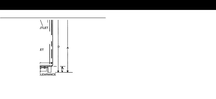
ROUGH IN DIMENSIONS
MODELS BTR(C) 120 THROUGH 400
|
|
|
|
|
|
|
|
|
|
|
|
|
|
|
|
|
|
|
|
|
|
|
|
|
|
|
|
|
|
|
|
|
|
|
|
|
|
See Models Below |
|
|
|
|
|
|
|||||||
|
|
|
|
|
* BTR(C) - 120 Models are approved for 5” (13 cm) venting using a 6” (15 cm) to 5” (13 cm) reducer. |
|
|
|
|
||||||||||||||||||||||||||||||||||||||||||
|
|
|
|
|
|
|
|
|
|
|
|
|
|
|
|
|
|
|
|
|
|
|
|
FIGURE 5. |
|
|
|
|
|
|
|
|
|
|
|
|
|
|
|
|
|
|
|
|
|||||||
|
|
|
|
|
|
|
|
|
|
|
|
|
|
|
TABLE 1A . BTR MODELS 120 THROUGH 400A |
|
|
|
|
|
|
|
|
|
|
|
|||||||||||||||||||||||||
|
|
|
|
|
|
|
|
|
|
|
|
|
|
|
|
|
|
|
|
|
|
|
|
|
|
|
|
|
|
|
|
|
|
|
|
|
|
|
|
|
|
|
|
|
|
|
|
||||
|
|
INPUT |
|
|
APPROX |
|
|
|
|
|
|
|
|
|
|
|
|
|
|
|
|
|
|
GAS |
|
|
|
VENT |
|
|
|
|
|
|
|
CONNECTIONS |
|
Approximate |
|||||||||||||
MODEL |
|
RATE |
|
|
TANK |
|
|
A |
|
|
B |
|
C |
|
|
D |
|
E |
|
F |
|
INLET |
H |
|
DIA |
|
J |
|
|
|
|
INLET |
|
|
|
OUTLET |
|
ship. Weight |
|||||||||||||
|
|
BTU/Hr. |
|
|
CAP. |
|
|
|
|
|
|
|
|
|
|
|
|
|
|
|
|
|
|
|
|
G |
|
|
|
|
|
I |
|
|
|
|
TOP |
FRONT |
BACK |
TOP |
FRONT |
|
BACK |
STD. |
|
ASME |
|||||
BTR120 |
|
120,000 BTU/Hr. |
|
71 Gal |
|
|
69.75” |
|
4.25” |
|
59.50” |
|
|
50.87” |
|
19.69” |
19” |
|
1/2” |
|
51.88” |
6” |
|
27.75” |
|
1.50” |
1.50” |
1.50” |
1.50” |
1.50” |
|
1.50” |
400 Lbs |
|
NA |
||||||||||||||||
|
|
35 Kw/Hr |
|
|
268 L |
|
|
177 cm |
11 cm |
|
151 cm |
|
|
129 cm |
50 cm |
48 cm |
|
1/2” |
|
132 cm |
15 cm |
71 cm |
|
1.50” |
1.50” |
1.50” |
1.50” |
1.50” |
|
1.50” |
182 Kg |
|
NA |
||||||||||||||||||
BTR154 |
|
154,000 BTU/Hr |
|
81 Gal |
|
|
73.00” |
|
4.25” |
|
66.50” |
|
|
57.87” |
|
19.69” |
19” |
|
1/2” |
|
59.00” |
6” |
|
27.75” |
|
1.50” |
1.50” |
1.50” |
1.50” |
1.50” |
|
1.50” |
470 Lbs |
|
NA |
||||||||||||||||
|
45 Kw/Hr |
|
|
307 L |
|
|
185 cm |
11 cm |
|
169 cm |
|
147 cm |
50 cm |
48 cm |
|
1/2” |
|
150 cm |
15 cm |
71 cm |
|
1.50” |
1.50” |
1.50” |
1.50” |
1.50” |
|
1.50” |
21 3 Kg |
|
NA |
||||||||||||||||||||
|
|
|
|
|
|
|
|
|
|
|
|
|
|||||||||||||||||||||||||||||||||||||||
BTR180 |
|
180,000 BTU/Hr |
|
81Gal |
|
|
67.50” |
|
4.50” |
|
62.00” |
|
|
53.62” |
|
20.50” |
21” |
|
1/2” |
|
54.62” |
6” |
|
27.75” |
|
1.50” |
1.50” |
1.50” |
1.50” |
1.50” |
|
1.50” |
470 Lbs |
|
NA |
||||||||||||||||
|
53 Kw/Hr |
|
|
307 L |
|
|
171 cm |
12 cm |
|
157 cm |
|
136 cm |
52 cm |
53 cm |
|
1/2” |
|
139 cm |
15 cm |
71 cm |
|
1.50” |
1.50” |
1.50” |
1.50” |
1.50” |
|
1.50” |
21 3 Kg |
|
NA |
||||||||||||||||||||
|
|
|
|
|
|
|
|
|
|
|
|
|
|||||||||||||||||||||||||||||||||||||||
BTR197 |
|
199,000 BTU/Hr |
|
100 Gal |
|
75.00” |
|
4.50” |
|
70.00” |
|
|
61.62” |
|
20.50” |
21” |
|
1/2” |
|
62.62” |
6” |
|
27.75” |
|
1.50” |
1.50” |
1.50” |
1.50” |
1.50” |
|
1.50” |
603 Lbs |
|
NA |
|||||||||||||||||
|
58 kW/Hr |
|
|
379 L |
|
|
192 cm |
12 cm |
|
178 cm |
|
157 cm |
52 cm |
53 cm |
|
1/2” |
|
159 cm |
15 cm |
71 cm |
|
1.50” |
1.50” |
1.50” |
1.50” |
1.50” |
|
1.50” |
273 Kg |
|
NA |
||||||||||||||||||||
|
|
|
|
|
|
|
|
|
|
|
|
|
|||||||||||||||||||||||||||||||||||||||
BTR198 |
|
199,000 BTU/Hr. |
|
100 Gal |
|
75.00” |
|
4.50” |
|
70.00” |
|
|
61.62” |
|
20.50” |
21” |
|
1/2” |
|
61.50” |
6” |
|
27.75” |
|
1.50” |
1.50” |
2.00” |
1.50” |
1.50” |
|
2.00” |
603 Lbs |
|
NA |
|||||||||||||||||
|
|
58 Kw/Hr |
|
|
379 L |
|
|
192 cm |
12 cm |
|
178 cm |
|
157 cm |
52 cm |
53 cm |
|
1/2” |
|
150 cm |
15 cm |
71 cm |
|
1.50” |
1.50” |
2.00” |
1.50” |
1.50” |
|
2.00” |
273 Kg |
|
NA |
|||||||||||||||||||
BTR199 |
|
199,000 BTU/Hr |
|
81 Gal |
|
|
67.50” |
|
4.50” |
|
62.00” |
|
|
53.62” |
|
20.50” |
21” |
|
1/2” |
|
54.62” |
6” |
|
27.75” |
|
1.50” |
1.50” |
1.50” |
1.50” |
1.50” |
|
1.50” |
470 Lbs |
|
NA |
||||||||||||||||
|
58 kW/Hr |
|
|
307 L |
|
|
171 cm |
12 cm |
|
157 cm |
|
136 cm |
52 cm |
53 cm |
|
1/2” |
|
139 cm |
15 cm |
71 cm |
|
1.50” |
1.50” |
1.50” |
1.50” |
1.50” |
|
1.50” |
21 3 Kg |
|
NA |
||||||||||||||||||||
|
|
|
|
|
|
|
|
|
|
|
|
|
|||||||||||||||||||||||||||||||||||||||
BTR 200 |
|
199,000 BTU/Hr |
|
100 Gal |
|
72.00” |
|
4.50” |
|
65.13” |
|
|
55.87” |
|
19.75” |
23” |
|
1/2” |
|
56.38” |
6” |
|
30.25” |
|
1.50” |
2.00” |
2.00” |
1.50” |
2.00” |
|
2.00” |
630 Lbs |
|
725 Lbs |
|||||||||||||||||
|
58 kW/Hr |
|
|
379 L |
|
|
183 cm |
12 cm |
|
165 cm |
|
142 cm |
50 cm |
58 cm |
|
1/2” |
|
143 cm |
15 cm |
77 cm |
|
1.50” |
2.00” |
2.00” |
1.50” |
2.00” |
|
2.00” |
286 Kg |
|
329 Kg |
||||||||||||||||||||
|
|
|
|
|
|
|
|
|
|
|
|
|
|||||||||||||||||||||||||||||||||||||||
BTR 250 |
|
250,000 BTU/Hr |
|
100 Gal |
|
72.00” |
|
4.50” |
|
65.13” |
|
|
55.87” |
|
19.75” |
23” |
|
1/2” |
|
56.38” |
8” |
|
30.25” |
|
1.50” |
2.00” |
2.00” |
1.50” |
2.00” |
|
2.00” |
630 Lbs |
|
725 Lbs |
|||||||||||||||||
|
72 kW/Hr |
|
|
379 L |
|
|
183 cm |
12 cm |
|
165 cm |
|
142 cm |
50 cm |
58 cm |
|
1/2” |
|
143 cm |
20 cm |
77 cm |
|
1.50” |
2.00” |
2.00” |
1.50” |
2.00” |
|
2.00” |
286 Kg |
|
329 Kg |
||||||||||||||||||||
|
|
|
|
|
|
|
|
|
|
|
|
|
|||||||||||||||||||||||||||||||||||||||
BTR 251 |
|
251,000 BTU/Hr |
|
65 Gal |
|
|
75.00” |
|
4.50” |
|
65.75” |
|
|
57.25” |
|
20.00” |
NA |
|
1/2” |
|
58.75 |
|
8” |
|
27.75” |
|
NA |
1.50” |
1.50” |
NA |
1.50” |
|
1.50” |
750Lbs |
|
862 Lbs |
|||||||||||||||
|
73 kW/Hr |
|
|
246 L |
|
|
191 cm |
12 cm |
|
167 cm |
|
145 cm |
51 cm |
NA |
|
1/2” |
|
149 cm |
20 cm |
70 cm |
|
NA |
1.50” |
1.50” |
NA |
1.50” |
|
1.50” |
341 Kg |
|
391 Kg |
||||||||||||||||||||
|
|
|
|
|
|
|
|
|
|
|
|
|
|||||||||||||||||||||||||||||||||||||||
BTR 275 |
|
275,000 BTU/Hr |
|
100 Gal |
|
72.00” |
|
4.50” |
|
65.13” |
|
|
55.87” |
|
19.75” |
23” |
|
1/2” |
|
56.38” |
8” |
|
30.25” |
|
1.50” |
2.00” |
2.00” |
1.50” |
2.00” |
|
2.00” |
630 Lbs |
|
725 Lbs |
|||||||||||||||||
|
80 kW/Hr |
|
|
379 L |
|
|
183 cm |
12 cm |
|
165 cm |
|
142 cm |
50 cm |
58 cm |
|
1/2” |
|
143 cm |
20 cm |
77 cm |
|
1.50” |
2.00” |
2.00” |
1.50” |
2.00” |
|
2.00” |
286 Kg |
|
329 Kg |
||||||||||||||||||||
|
|
|
|
|
|
|
|
|
|
|
|
|
|||||||||||||||||||||||||||||||||||||||
BTR 305 |
|
305,000 BTU/Hr |
|
65 Gal |
|
|
75.00” |
|
4.50” |
|
65.75” |
|
|
57.25” |
|
20.00” |
NA |
|
1/2” |
|
58.75 |
|
8” |
|
27.75” |
|
NA |
1.50” |
1.50” |
NA |
1.50” |
|
1.50” |
750 Lbs |
|
862 Lbs |
|||||||||||||||
|
89 kW/Hr |
|
|
246 L |
|
|
191 cm |
12 cm |
|
167 cm |
|
145 cm |
51 cm |
NA |
|
1/2” |
|
149 cm |
20 cm |
70 cm |
|
NA |
1.50” |
1.50” |
NA |
1.50” |
|
1.50” |
341 Kg |
|
391 Kg |
||||||||||||||||||||
|
|
|
|
|
|
|
|
|
|
|
|
|
|||||||||||||||||||||||||||||||||||||||
BTR 365 |
|
365,000 BTU/Hr |
|
85 Gal |
|
|
79.50” |
|
4.50” |
|
70.25” |
|
|
62.50” |
|
22.50” |
23” |
|
3/4” |
|
63.00 |
|
8” |
|
27.75” |
|
1.50” |
1.50” |
1.50” |
1.50” |
1.50” |
|
1.50” |
725 Lbs |
|
833 Lbs |
|||||||||||||||
|
107kW/Hr |
|
|
322 L |
|
|
202 cm |
12 cm |
|
178 cm |
|
159 cm |
57 cm |
58 cm |
|
3/4” |
|
160 cm |
20 cm |
70 cm |
|
1.50” |
1.50” |
1.50” |
1.50” |
1.50” |
|
1.50” |
329 Kg |
|
379 Kg |
||||||||||||||||||||
|
|
|
|
|
|
|
|
|
|
|
|
|
|||||||||||||||||||||||||||||||||||||||
BTR 400 |
|
390,000 BTU/Hr |
|
100 Gal |
|
75.50” |
|
4.50” |
|
67.50” |
|
|
58.25” |
|
26.75” |
23” |
|
3/4” |
|
59.00” |
8” |
|
30.25” |
|
1.50” |
2.00” |
2.00” |
1.50” |
2.00” |
|
2.00” |
760 Lbs |
|
874 Lbs |
|||||||||||||||||
|
114kW/Hr |
|
|
379 L |
|
|
192 cm |
12 cm |
|
171 cm |
|
|
148 cm |
68 cm |
58 cm |
|
3/4” |
|
150 cm |
20 cm |
77 cm |
|
1.50” |
2.00” |
2.00” |
1.50” |
2.00” |
|
2.00” |
345 Kg |
|
396 Kg |
|||||||||||||||||||
|
|
|
|
|
|
|
|
|
|
|
|
|
|
||||||||||||||||||||||||||||||||||||||
|
|
|
|
|
|
|
|
|
|
|
|
|
|
TABLE 1B. BTRC MODELS 120 THROUGH 400/A |
|
|
|
|
|
|
|
|
|
|
|
||||||||||||||||||||||||||
|
|
|
|
|
|
|
|
|
|
|
|
|
|
|
|
|
|
|
|
|
|
|
|
|
|
|
|
|
|
|
|
|
|
|
|
|
|
|
|
|
|
|
|
||||||||
|
|
INPUT |
APPROX. |
|
|
|
|
|
|
|
|
|
|
|
|
|
|
|
|
|
|
|
GAS |
|
|
|
|
VENT |
|
|
|
|
|
|
|
|
CONNECTIONS |
|
Approximate |
||||||||||||
MODEL |
|
RATE |
|
TANK |
|
|
|
A |
|
|
B |
|
|
C |
|
|
|
D |
|
|
E |
|
F |
INLET |
|
|
H |
|
|
DIA |
|
|
J |
|
|
|
|
INLET |
|
|
|
OUTLET |
|
ship. Weight |
|||||||
|
|
BTU/Hr. |
|
|
CAP. |
|
|
|
|
|
|
|
|
|
|
|
|
|
|
|
|
|
|
|
|
|
G |
|
|
|
|
|
I |
|
|
|
|
TOP |
FRONT |
|
BACK |
|
TOP |
FRONT |
|
BACK |
STD. |
|
ASME |
||
BTRC120 |
120,000 BTU/Hr. |
|
71 Gal |
|
|
69.75” |
|
4.25” |
|
59.50” |
|
|
50.87” |
|
19.69” |
|
19” |
|
1/2” |
|
51.88” |
|
|
6” |
|
27.75” |
1.50” |
|
1.50” |
|
1.50” |
|
1.50” |
1.50” |
|
1.50” |
400 LBS |
|
NA |
||||||||||||
|
|
35 Kw/Hr |
|
|
268 L |
|
177 cm |
|
11 cm |
|
151 cm |
|
129 cm |
|
50 cm |
48 cm |
|
1/2” |
|
132 cm |
|
15 cm |
|
71 cm |
1.50” |
|
1.50” |
|
1.50” |
|
1.50” |
1.50” |
|
1.50” |
182 Kg |
|
NA |
||||||||||||||
BTRC154 |
|
154,000 BTU/Hr |
|
81 Gal |
|
|
73.00” |
|
4.25” |
|
66.50” |
|
|
57.87” |
|
19.69” |
|
19” |
|
1/2” |
|
59.00” |
|
|
6” |
|
27.75” |
1.50” |
|
1.50” |
|
1.50” |
|
1.50” |
1.50” |
|
1.50” |
470 LBS |
|
NA |
|||||||||||
|
|
45 Kw/Hr |
|
|
307 L |
|
185 cm |
|
11 cm |
|
169 cm |
|
147 cm |
|
50 cm |
48 cm |
|
1/2” |
|
150 cm |
|
15 cm |
|
71 cm |
1.50” |
|
1.50” |
|
1.50” |
|
1.50” |
1.50” |
|
1.50” |
213Kq |
|
NA |
||||||||||||||
BTRC180 |
|
180,000 BTU/Hr |
|
76 Gal |
|
|
70.50” |
|
4.25” |
|
63.75” |
|
|
55.13” |
|
17.75” |
|
19” |
|
1/2” |
|
56.50” |
|
|
6” |
|
27.75” |
1.50” |
|
1.50” |
|
1.50” |
|
1.50” |
1.50” |
|
1.50” |
470 LBS |
|
NA |
|||||||||||
|
|
53 Kw/Hr |
|
|
288 L |
|
179 cm |
|
11 cm |
|
162 cm |
|
140 cm |
|
45 cm |
48 cm |
|
1/2” |
|
144 cm |
|
15 cm |
|
71 cm |
1.50” |
|
1.50” |
|
1.50” |
|
1.50” |
1.50” |
|
1.50” |
213Kq |
|
NA |
||||||||||||||
BTRC197 |
|
199,000 BTU/Hr |
|
94 Gal |
|
|
81.50” |
|
4.25” |
|
74.75” |
|
|
66.13” |
|
17.75” |
|
19” |
|
1/2” |
|
67.50” |
|
|
6” |
|
27.75” |
1.50” |
|
1.50” |
|
1.50” |
|
1.50” |
1.50” |
|
1.50” |
603 LBS |
|
NA |
|||||||||||
|
|
58 kW/Hr |
|
|
356 L |
|
207 cm |
|
11 cm |
|
190 cm |
|
168 cm |
|
45 cm |
48 cm |
|
1/2” |
|
171 cm |
|
15 cm |
|
71 cm |
1.50” |
|
1.50” |
|
1.50” |
|
1.50” |
1.50” |
|
1.50” |
273 Kg |
|
NA |
||||||||||||||
BTRC199 |
|
199,000 BTU/Hr |
|
76 Gal |
|
|
70.50” |
|
4.25” |
|
63.75” |
|
|
55.13” |
|
17.75” |
|
19” |
|
1/2” |
|
56.50” |
|
|
6” |
|
27.75” |
1.50” |
|
1.50” |
|
1.50” |
|
1.50” |
1.50” |
|
1.50” |
470 LBS |
|
NA |
|||||||||||
|
|
58 kW/Hr |
|
|
288 L |
|
179 cm |
|
11 cm |
|
162 cm |
|
140 cm |
|
45 cm |
48 cm |
|
1/2” |
|
144 cm |
|
15 cm |
|
71 cm |
1.50” |
|
1.50” |
|
1.50” |
|
1.50” |
1.50” |
|
1.50” |
213Kq |
|
NA |
||||||||||||||
BTRC200 |
|
199,000 BTU/Hr |
|
100 Gal |
|
|
72.00” |
|
4.50” |
|
65.13” |
|
|
55.87” |
|
19.75” |
|
23” |
|
1/2” |
|
56.38” |
|
|
6” |
|
30.25” |
1.50” |
|
2.00” |
|
2.00” |
|
1.50” |
2.00” |
|
2.00” |
630 Ibs |
|
725 Ibs |
|||||||||||
|
|
58 kW/Hr |
|
379 L |
|
183 cm |
12 cm |
|
165 cm |
|
142 cm |
|
50 cm |
58 cm |
|
1/2” |
|
143 cm |
|
15 cm |
|
77 cm |
1.50” |
|
2.00” |
|
2.00” |
|
1.50” |
2.00” |
|
2.00” |
286 Kg |
|
329 Kg |
||||||||||||||||
BTRC250 |
|
250,000 BTU/Hr |
|
100 Gal |
|
|
72.00” |
|
4.50” |
|
65.13” |
|
|
55.87” |
|
19.75” |
|
23” |
|
1/2” |
|
56.38” |
|
|
8” |
|
30.25” |
1.50” |
|
2.00” |
|
2.00” |
|
1.50” |
2.00” |
|
2.00” |
630 Ibs |
|
725 Ibs |
|||||||||||
|
|
72 kW/Hr |
|
379 L |
|
183 cm |
12 cm |
|
165 cm |
|
142 cm |
|
50 cm |
58 cm |
|
1/2” |
|
143 cm |
|
20 cm |
|
77 cm |
1.50” |
|
2.00” |
|
2.00” |
|
1.50” |
2.00” |
|
2.00” |
286 Kg |
|
329 Kg |
||||||||||||||||
BTRC251 |
|
251,000 BTU/Hr |
|
65 Gal |
|
|
75.00” |
|
4.50” |
|
65.75” |
|
|
57.25” |
|
20.00” |
|
NA |
|
1/2” |
58.8 149 |
|
|
8” |
|
27.75” |
|
NA |
|
1.50” |
|
1.50” |
|
NA |
1.50” |
|
1.50” |
750 Ibs |
|
862 Ibs |
|||||||||||
|
|
73 kW/Hr |
|
|
246 L |
|
191 cm |
12 cm |
|
167 cm |
|
145 cm |
|
51 cm |
|
NA |
|
1/2” |
|
|
cm |
|
20 cm |
|
70 cm |
|
NA |
|
1.50” |
|
1.50” |
|
NA |
1.50” |
|
1.50” |
341 Kg |
|
391 Kg |
||||||||||||
BTRC275 |
|
275,000 BTU/Hr |
|
100 Gal |
|
|
72.00” |
|
4.50” |
|
65.13” |
|
|
55.87” |
|
19.75” |
|
23” |
|
1/2” |
|
56.38” |
|
|
8” |
|
30.25” |
1.50” |
|
2.00” |
|
2.00” |
|
1.50” |
2.00” |
|
2.00” |
630 Ibs |
|
725 Ibs |
|||||||||||
|
|
80 kW/Hr |
|
379 L |
|
183 cm |
12 cm |
|
165 cm |
|
142 cm |
|
50 cm |
58 cm |
|
1/2” |
|
143 cm |
|
20 cm |
|
77 cm |
1.50” |
|
2.00” |
|
2.00” |
|
1.50” |
2.00” |
|
2.00” |
286 Kg |
|
329 Kg |
||||||||||||||||
BTRC305 |
|
305,000 BTU/Hr |
|
65 Gal |
|
|
75.00” |
|
4.50” |
|
65.75” |
|
|
57.25” |
|
20.00” |
|
NA |
|
1/2” |
58.8 149 |
|
|
8” |
|
27.75” |
|
NA |
|
1.50” |
|
1.50” |
|
NA |
1.50” |
|
1.50” |
750 Ibs |
|
862 Ibs |
|||||||||||
|
|
89 kW/Hr |
|
|
246 L |
|
191 cm |
12 cm |
|
167 cm |
|
145 cm |
|
51 cm |
|
NA |
|
1/2” |
|
|
cm |
|
20 cm |
|
70 cm |
|
NA |
|
1.50” |
|
1.50” |
|
NA |
1.50” |
|
1.50” |
341 Kg |
|
391 Kg |
||||||||||||
BTRC365 |
|
365,000 BTU/Hr |
|
65 Gal |
|
|
75.00” |
|
4.50” |
|
65.75” |
|
|
57.25” |
|
20.00” |
|
NA |
|
3/4” |
|
|
58.8 |
|
|
8” |
|
27.75” |
|
NA |
|
1.50” |
|
1.50” |
|
NA |
1.50” |
|
1.50” |
750 Ibs |
|
862 Ibs |
|||||||||
|
|
107kW/Hr |
|
|
246 L |
|
191 cm |
12 cm |
|
167 cm |
|
145 cm |
|
51 cm |
|
NA |
|
3/4” |
|
149cm |
|
20 cm |
|
70 cm |
|
NA |
|
1.50” |
|
1.50” |
|
NA |
1.50” |
|
1.50” |
341 Kg |
|
391 Kg |
|||||||||||||
BTRC400 |
|
390,000 BTU/Hr |
|
100 Gal |
|
|
75.50” |
|
4.50” |
|
67.50” |
|
|
58.25” |
|
26.75” |
|
23” |
|
3/4” |
|
59.00” |
|
|
8” |
|
30.25” |
1.50” |
|
2.00” |
|
2.00” |
|
1.50” |
2.00” |
|
2.00” |
760 Ibs |
|
874 Ibs |
|||||||||||
|
|
114kW/Hr |
|
379 L |
|
192 cm |
12 cm |
|
171 cm |
|
148 cm |
|
68 cm |
58 cm |
|
3/4” |
|
150 cm |
|
20 cm |
|
77 cm |
1.50” |
|
2.00” |
|
2.00” |
|
1.50” |
2.00” |
|
2.00” |
345 Kg |
|
396 Kg |
||||||||||||||||
8

INSTALLATION CONSIDERATIONS
TABLE 2. HEATER PERFORMANCE DATA BTR MODELS
|
|
|
|
INPUT |
APPROX. |
EFF. |
|
|
|
|
|
|
|
RECOVERY RATING CAPACITIES (GPHAND LPH) |
|
|
|||||||||||||||||||||
MODEL |
|
|
|
RATE |
GAL. |
|
|
|
|
|
|
|
|
|
|
|
|
|
|
|
|
|
|
|
|
|
|
|
|
|
|
|
|
|
|
||
|
30°F |
40°F |
50°F |
|
60°F |
|
70°F |
80°F |
90°F |
|
100°F |
110°F |
|
120°F |
|
130°F |
|
140°F |
|||||||||||||||||||
|
|
|
|
BTUH |
CAP. |
|
% |
|
|
|
|
|
|
|
|
|
|
|
|
|
|
|
|
|
|
|
|
|
|
|
|
|
|
|
|
|
|
|
|
|
|
|
17°C |
22° C |
28°C |
|
33°C |
|
39° C |
44°C |
50°C |
|
56°C |
61°C |
|
67°C |
|
|
72°C |
|
78°C |
||||||||||||||
|
|
|
|
|
|
|
|
|
|
|
|
|
|||||||||||||||||||||||||
BTR |
|
|
120,000 BTUH |
71Gal |
|
80 |
388 |
291 |
233 |
|
|
194 |
|
166 |
|
145 |
|
129 |
|
|
116 |
|
106 |
|
|
97 |
|
|
90 |
|
|
83 |
|||||
120 |
|
|
|
35Kw/Hr |
268L |
|
1469 |
1102 |
882 |
|
|
734 |
|
628 |
|
549 |
|
488 |
|
|
439 |
|
401 |
|
|
367 |
|
|
341 |
|
|
314 |
|||||
|
|
|
|
|
|
|
|
|
|
|
|
|
|
|
|
|
|
|
|||||||||||||||||||
BTR |
|
|
154,000 BTUH |
81Gal |
|
80 |
498 |
373 |
299 |
|
|
249 |
|
213 |
|
187 |
|
166 |
|
|
149 |
|
136 |
|
|
124 |
|
|
115 |
|
|
107 |
|||||
154 |
|
|
|
45Kw/Hr |
306L |
|
1885 |
1412 |
1132 |
|
|
943 |
|
806 |
|
708 |
|
628 |
|
|
564 |
|
515 |
|
|
469 |
|
|
435 |
|
|
405 |
|||||
|
|
|
|
|
|
|
|
|
|
|
|
|
|
|
|
|
|
|
|||||||||||||||||||
BTR |
|
|
180,000 BTUH |
81Gal |
|
80 |
579 |
434 |
347 |
|
|
289 |
|
248 |
|
217 |
|
193 |
|
|
174 |
|
158 |
|
|
145 |
|
|
134 |
|
|
124 |
|||||
180 |
|
|
|
53Kw/Hr |
306L |
|
2192 |
1643 |
1314 |
|
|
1094 |
|
939 |
|
821 |
|
731 |
|
|
659 |
|
598 |
|
|
549 |
|
|
507 |
|
|
469 |
|||||
|
|
|
|
|
|
|
|
|
|
|
|
|
|
|
|
|
|
|
|||||||||||||||||||
BTR |
|
|
199,000 BTUH |
100Gal |
|
80 |
643 |
482 |
386 |
|
|
322 |
|
276 |
|
241 |
|
214 |
|
|
193 |
|
175 |
|
|
161 |
|
|
148 |
|
|
132 |
|||||
197 |
|
|
|
58Kw/Hr |
379L |
|
2434 |
1825 |
1461 |
|
|
1219 |
|
1045 |
|
912 |
|
810 |
|
|
731 |
|
662 |
|
|
609 |
|
|
560 |
|
|
500 |
|||||
|
|
|
|
|
|
|
|
|
|
|
|
|
|
|
|
|
|
|
|||||||||||||||||||
BTR |
|
|
199,000 BTUH |
100Gal |
|
80 |
643 |
482 |
386 |
|
|
322 |
|
276 |
|
241 |
|
214 |
|
|
193 |
|
175 |
|
|
161 |
|
|
148 |
|
|
132 |
|||||
198 |
|
|
|
58Kw/Hr |
379L |
|
2434 |
1825 |
1461 |
|
|
1219 |
|
1045 |
|
912 |
|
810 |
|
|
731 |
|
662 |
|
|
609 |
|
|
560 |
|
|
500 |
|||||
|
|
|
|
|
|
|
|
|
|
|
|
|
|
|
|
|
|
|
|||||||||||||||||||
BTR |
|
|
199,000 BTUH |
81Gal |
|
80 |
614 |
461 |
368 |
|
|
307 |
|
263 |
|
230 |
|
205 |
|
|
184 |
|
167 |
|
|
154 |
|
|
142 |
|
|
132 |
|||||
199 |
|
|
|
58Kw/Hr |
306L |
|
2324 |
1745 |
1393 |
|
|
1162 |
|
996 |
|
871 |
|
776 |
|
|
697 |
|
632 |
|
|
583 |
|
|
538 |
|
|
500 |
|||||
|
|
|
|
|
|
|
|
|
|
|
|
|
|
|
|
|
|
|
|||||||||||||||||||
BTR |
|
|
199,000 BTUH |
100Gal |
|
80 |
643 |
482 |
386 |
|
|
322 |
|
276 |
|
241 |
|
214 |
|
|
193 |
|
175 |
|
|
161 |
|
|
148 |
|
|
132 |
|||||
200 |
|
|
|
58Kw/Hr |
379L |
|
2434 |
1825 |
1461 |
|
|
1219 |
|
1045 |
|
912 |
|
810 |
|
|
731 |
|
662 |
|
|
609 |
|
|
560 |
|
|
500 |
|||||
|
|
|
|
|
|
|
|
|
|
|
|
|
|
|
|
|
|
|
|||||||||||||||||||
BTR |
|
|
250,000 BTUH |
100Gal |
|
80 |
808 |
606 |
485 |
|
|
404 |
|
346 |
|
303 |
|
269 |
|
|
242 |
|
220 |
|
|
202 |
|
|
186 |
|
|
173 |
|||||
250 |
|
|
|
73Kw/Hr |
379L |
|
3059 |
2294 |
1835 |
|
|
1529 |
|
1311 |
|
1147 |
|
1020 |
|
918 |
|
834 |
|
|
765 |
|
|
706 |
|
|
655 |
||||||
|
|
|
|
|
|
|
|
|
|
|
|
|
|
|
|
|
|
||||||||||||||||||||
BTR |
|
|
251,000BTUH |
65Gal |
|
80 |
811 |
608 |
487 |
|
|
406 |
|
348 |
|
304 |
|
270 |
|
|
243 |
|
221 |
|
|
203 |
|
|
187 |
|
|
174 |
|||||
251 |
|
|
|
73Kw/Hr |
246L |
|
3071 |
2303 |
1843 |
|
|
1536 |
|
1316 |
|
1152 |
|
1024 |
|
921 |
|
838 |
|
|
768 |
|
|
709 |
|
|
658 |
||||||
|
|
|
|
|
|
|
|
|
|
|
|
|
|
|
|
|
|
||||||||||||||||||||
BTR |
|
|
275,000 BTUH |
100Gal |
|
80 |
889 |
667 |
533 |
|
|
444 |
|
381 |
|
333 |
|
296 |
|
|
267 |
|
242 |
|
|
222 |
|
|
205 |
|
|
190 |
|||||
275 |
|
|
|
80Kw/Hr |
379L |
|
3365 |
2524 |
2019 |
|
|
1682 |
|
1442 |
|
1262 |
|
1122 |
|
|
1009 |
918 |
|
|
841 |
|
|
776 |
|
|
721 |
||||||
|
|
|
|
|
|
|
|
|
|
|
|
|
|
|
|
|
|
||||||||||||||||||||
BTR |
|
|
305,000 BTUH |
65Gal |
|
80 |
986 |
739 |
592 |
|
|
493 |
|
423 |
|
370 |
|
329 |
|
|
296 |
|
269 |
|
|
246 |
|
|
228 |
|
|
211 |
|||||
305 |
|
|
|
89Kw/Hr |
246L |
|
3732 |
2799 |
2239 |
|
|
1866 |
|
1599 |
|
1399 |
|
1244 |
|
1120 |
|
1018 |
|
|
933 |
|
|
861 |
|
|
800 |
||||||
|
|
|
|
|
|
|
|
|
|
|
|
|
|
|
|
|
|
||||||||||||||||||||
BTR |
|
|
365,000 |
85Gal |
|
80 |
1180 |
885 |
708 |
|
|
590 |
|
506 |
|
442 |
|
393 |
|
|
354 |
|
322 |
|
|
295 |
|
|
272 |
|
|
253 |
|||||
365 |
|
|
|
107Kw/Hr |
322L |
|
4466 |
3349 |
2680 |
|
|
2233 |
|
1914 |
|
1675 |
|
1489 |
|
1340 |
1218 |
|
|
1116 |
|
|
1031 |
|
|
957 |
|||||||
|
|
|
|
|
|
|
|
|
|
|
|
|
|
|
|
|
|||||||||||||||||||||
BTR |
|
|
390,000 BTUH 1 |
100Gal |
|
80 |
1293 |
970 |
|
776 |
|
|
646 |
|
554 |
|
485 |
|
431 |
|
|
388 |
|
353 |
|
|
323 |
|
|
298 |
|
|
277 |
||||
400 |
|
|
|
14Kw/Hr |
379L |
|
4894 |
3671 |
2936 |
|
|
2447 |
|
2097 |
|
1835 |
|
1631 |
|
|
1468 |
1335 |
|
|
1224 |
|
|
1129 |
|
|
1049 |
||||||
|
|
|
|
|
|
|
|
|
|
|
|
|
|
|
|
|
|
||||||||||||||||||||
|
|
|
|
|
TABLE 3. HEATER PERFORMANCE DATA BTRC MODELS |
|
|
|
|
|
|
|
|
|
|
|
|
||||||||||||||||||||
|
|
|
|
|
|
|
|
|
|
|
|
|
|
|
|
|
|
|
|
|
|
|
|
|
|
|
|
|
|
|
|
||||||
MODEL |
|
INPUT RATE |
APPROX. |
EFF. |
|
|
|
|
|
|
RECOVERY RATING CAPACITIES (GPHAND LPH) |
|
|
|
|
|
|
|
|
|
|||||||||||||||||
|
|
BTUH |
GAL. |
|
% |
30°F |
40°F |
50°F |
|
60°F |
|
70°F |
|
80°F |
|
90°F |
|
100° F |
|
110°F |
|
|
120°F |
|
130° F |
|
|
140°F |
|||||||||
|
|
|
|
|
CAP. |
|
|
17°C |
22° C |
28°C |
|
33°C |
|
39° C |
|
44°C |
|
50°C |
|
|
56°C |
|
61°C |
|
|
67°C |
|
|
72°C |
|
|
78°C |
|||||
BTRC |
|
120,000 BTUH |
71Gal |
|
80 |
388 |
291 |
|
233 |
|
|
194 |
166 |
|
145 |
|
129 |
|
116 |
|
106 |
|
|
97 |
|
90 |
|
83 |
|||||||||
120 |
|
|
|
35Kw/Hr |
268L |
|
1469 |
1102 |
|
882 |
|
|
734 |
628 |
|
549 |
|
488 |
|
439 |
|
401 |
|
|
367 |
|
341 |
|
314 |
||||||||
|
|
|
|
|
|
|
|
|
|
|
|
|
|
|
|
||||||||||||||||||||||
BTRC |
|
154,000 BTUH |
81Gal |
|
80 |
498 |
373 |
|
299 |
|
|
249 |
213 |
|
187 |
|
166 |
|
149 |
|
136 |
|
|
124 |
|
115 |
|
107 |
|||||||||
154 |
|
|
|
45Kw/Hr |
306L |
|
1885 |
1412 |
1132 |
|
|
943 |
806 |
|
708 |
|
628 |
|
564 |
|
515 |
|
|
469 |
|
435 |
|
405 |
|||||||||
|
|
|
|
|
|
|
|
|
|
|
|
|
|
|
|||||||||||||||||||||||
BTRC |
|
180,000 BTUH |
76Gal |
|
80 |
579 |
434 |
|
347 |
|
|
289 |
248 |
|
217 |
|
193 |
|
174 |
|
158 |
|
|
145 |
|
134 |
|
124 |
|||||||||
180 |
|
|
|
53Kw/Hr |
288L |
|
2192 |
1643 |
1314 |
|
|
1094 |
939 |
|
821 |
|
731 |
|
659 |
|
598 |
|
|
549 |
|
507 |
|
469 |
|||||||||
|
|
|
|
|
|
|
|
|
|
|
|
|
|
|
|||||||||||||||||||||||
BTRC |
|
199,000 BTUH |
94Gal |
|
80 |
643 |
482 |
|
386 |
|
|
322 |
276 |
|
241 |
|
214 |
|
193 |
|
175 |
|
|
161 |
|
148 |
|
132 |
|||||||||
197 |
|
|
|
58Kw/Hr |
356L |
|
2434 |
1825 |
1461 |
|
|
1219 |
1045 |
|
912 |
|
810 |
|
731 |
|
662 |
|
|
609 |
|
560 |
|
500 |
|||||||||
|
|
|
|
|
|
|
|
|
|
|
|
|
|
|
|||||||||||||||||||||||
BTRC |
|
199,000 BTUH |
76Gal |
|
80 |
614 |
461 |
|
368 |
|
|
307 |
263 |
|
230 |
|
205 |
|
184 |
|
167 |
|
|
154 |
|
142 |
|
132 |
|||||||||
199 |
|
|
|
58Kw/Hr |
288L |
|
2324 |
1745 |
1393 |
|
|
1162 |
996 |
|
871 |
|
776 |
|
697 |
|
632 |
|
|
583 |
|
538 |
|
500 |
|||||||||
|
|
|
|
|
|
|
|
|
|
|
|
|
|
|
|||||||||||||||||||||||
BTRC |
|
199,000 BTUH |
100Gal |
|
80 |
643 |
482 |
|
386 |
|
|
322 |
276 |
|
241 |
|
214 |
|
193 |
|
175 |
|
|
161 |
|
148 |
|
132 |
|||||||||
200 |
|
|
|
58Kw/Hr |
379L |
|
2434 |
1825 |
1461 |
|
|
1219 |
1045 |
|
912 |
|
810 |
|
731 |
|
662 |
|
|
609 |
|
560 |
|
500 |
|||||||||
|
|
|
|
|
|
|
|
|
|
|
|
|
|
|
|||||||||||||||||||||||
BTRC |
|
250,000 BTUH |
100Gal |
|
80 |
808 |
606 |
|
485 |
|
|
404 |
346 |
|
303 |
|
269 |
|
242 |
|
220 |
|
|
202 |
|
186 |
|
173 |
|||||||||
250 |
|
|
|
73Kw/Hr |
379L |
|
3059 |
2294 |
1835 |
|
|
1529 |
1311 |
|
1147 |
|
1020 |
|
918 |
|
834 |
|
|
765 |
|
706 |
|
655 |
|||||||||
|
|
|
|
|
|
|
|
|
|
|
|
|
|
|
|||||||||||||||||||||||
BTRC |
|
251,000BTUH |
65Gal |
|
80 |
811 |
608 |
|
487 |
|
|
406 |
348 |
|
304 |
|
270 |
|
243 |
|
221 |
|
|
203 |
|
187 |
|
174 |
|||||||||
251 |
|
|
|
73Kw/Hr |
246L |
|
3071 |
2303 |
1843 |
|
|
1536 |
1316 |
|
1152 |
|
1024 |
|
921 |
|
838 |
|
|
768 |
|
709 |
|
658 |
|||||||||
|
|
|
|
|
|
|
|
|
|
|
|
|
|
|
|||||||||||||||||||||||
BTRC |
|
275,000 BTUH |
100Gal |
|
80 |
889 |
667 |
|
533 |
|
|
444 |
381 |
|
333 |
|
296 |
|
267 |
|
242 |
|
|
222 |
|
205 |
|
190 |
|||||||||
275 |
|
|
|
80Kw/Hr |
379L |
|
3365 |
2524 |
2019 |
|
|
1682 |
1442 |
|
1262 |
|
1122 |
|
1009 |
|
918 |
|
|
841 |
|
776 |
|
721 |
|||||||||
|
|
|
|
|
|
|
|
|
|
|
|
|
|
|
|||||||||||||||||||||||
BTRC |
|
305,000 BTUH |
65Gal |
|
80 |
986 |
739 |
|
592 |
|
|
493 |
423 |
|
370 |
|
329 |
|
296 |
|
269 |
|
|
246 |
|
228 |
|
211 |
|||||||||
305 |
|
|
|
89Kw/Hr |
246L |
|
3732 |
2799 |
2239 |
|
|
1866 |
1599 |
|
1399 |
|
1244 |
|
1120 |
|
1018 |
|
|
933 |
|
861 |
|
800 |
|||||||||
|
|
|
|
|
|
|
|
|
|
|
|
|
|
|
|||||||||||||||||||||||
BTRC |
|
360,000 BTUH |
65Gal |
|
80 |
1164 |
873 |
|
698 |
|
|
582 |
499 |
|
436 |
|
388 |
|
349 |
|
317 |
|
|
291 |
|
269 |
|
249 |
|||||||||
365 |
|
|
|
105Kw/Hr |
246L |
|
4405 |
3304 |
2643 |
|
|
2202 |
1888 |
|
1652 |
|
1468 |
|
1321 |
|
1201 |
|
|
1101 |
|
1016 |
|
944 |
|||||||||
|
|
|
|
|
|
|
|
|
|
|
|
|
|
|
|||||||||||||||||||||||
BTRC |
|
390,000 BTUH |
100Gal |
|
80 |
1293 |
970 |
|
776 |
|
|
646 |
554 |
|
485 |
|
431 |
|
388 |
|
353 |
|
|
323 |
|
298 |
|
277 |
|||||||||
400 |
|
|
|
114Kw/Hr |
379L |
|
4894 |
3671 |
2936 |
|
|
2447 |
2097 |
|
1835 |
|
1631 |
|
1468 |
|
1335 |
|
|
1224 |
|
1129 |
|
1049 |
|||||||||
|
|
|
|
|
|
|
|
|
|
|
|
|
|
|
|||||||||||||||||||||||
|
|
|
|
|
|
TABLE 4. GAS AND ELECTRICAL CHARACTERISTICS |
|
|
|
|
|
|
|
|
|
|
|
|
|
|
|
||||||||||||||||
|
|
|
|
|
|
|
|
|
|
|
|
|
|
|
|
|
|
|
|
|
|
|
|
|
|
|
|
|
|
|
|
|
|
||||
|
|
|
|
|
|
|
|
|
Gas Supply Pressure |
|
|
|
|
|
|
|
|
|
|
|
|
|
|
|
|
|
|
|
|
|
|
|
|||||
Model |
|
Type of Gas |
|
|
Minimum |
|
|
Maximum |
Gas Manifold Pressure |
|
|
Volts/Hz |
|
|
Amperes |
||||||||||||||||||||||
All Models |
|
Natural |
|
|
4.5" W.C. (1.12 kPa) |
|
14" W.C. (3.48 kPa) |
3.5" W.C. (0.87 kPa) |
|
|
120/60 |
|
|
|
|
<5 |
|||||||||||||||||||||
All Models |
|
Propane |
|
11.0" W.C. (2.74kPa) |
|
14" W.C. (3.48kPa) |
10.0" W.C. (2.49 kPa) |
|
|
120/60 |
|
|
|
|
<5 |
||||||||||||||||||||||
9
INSTALLATION CONSIDERATIONS
LOCATING THE WATER HEATER
CAUTION
Property Damage Hazard
•All water heaters eventually leak.
•Do not install without adequate drainage.
When installing the heater, consideration must be given to proper location. Location selected should be as close to the stack or chimney as practicable, with adequate air supply and as centralized with the piping system as possible.
Fire or Explosion Hazard
 Do not store or use gasoline or other flammable vapors and liquids in the vicinity of this or any other appliance.
 Avoid all ignition sources if you smell gas.
 Do not expose water heater controls to excessive gas pressure.
 Use only the gas shown on the water heater rating label.
 Maintain required clearances to combustibles.
 Keep ignition sources away from faucets after extended periods of non-use.
Read instruction manual before installing, using or servicing water heater.
There is a risk in using fuel burning appliances such as gas water heaters in rooms, garages or other areas where gasoline, other flammable liquids or engine driven equipment or vehicles are stored, operated or repaired. Flammable vapors are heavy and travel along the floor and may be ignited by the heater’s igniter or main burner flames causing fire or explosion. Some local codes permit operation of gas appliances in such areas if they are installed 18” or more above the floor. This may reduce the risk if location in such an area cannot be avoided.
Do not install this water heater directly on a carpeted floor. A fire hazard may result. Instead the water heater must be placed on a metal or wood panel extending beyond the full width and depth by at least 3 inches in any direction. If the heater is installed in a carpeted alcove, the entire floor shall be covered by the panel. Also, see the DRAINING requirements in MAINTENANCE Section.
The heater shall be located or protected so it is not subject to physical damage by a moving vehicle.
Flammable items, pressurized containers or any other potential fire hazardous articles must never be placed on or adjacent to the heater. Open containers or flammable material should not be stored or used in the same room with the heater.
The heater must not be located in an area where it will be subject to freezing.
Locate it near a floor drain. The heater should be located in an area where leakage from heater or connections will not result in damage to adjacent area or to lower floors of the structure.
When such locations cannot be avoided, a suitable metal drain pan should be installed under heater. Such pans should be fabricated with sides at least 2” deep, with length and width at least 2” greater than diameter of heater and must be piped to an adequate drain. Pan must not restrict combustion air flow.
CLEARANCES
These heaters are approved for installation on combustible flooring in an alcove when the minimum clearance from combustion or non-combustible construction are followed as indicated in Figure 6 and Table 5.
In all installations the minimum combustible clearances from draft hood surface or vent piping shall be 6” (152mm). Vent piping passing through a combustible wall or ceiling must be a continuous run (no joints) and retain 6” (152mm) clearance unless an approved reducing thimble is used.
A service clearance of 24” (610mm) should be maintained from serviceableparts,suchasreliefvalves,baffles,thermostats,cleanout openings or drain valves.
TABLE 5. INSTALLATION CLEARANCES
|
A |
B |
C |
D |
|
(RIGHT SIDE) |
(LEFTSIDE) |
(BACK) |
(CEILING) |
|
|
|
|
|
120 |
1” (2.54 cm) |
1” (2.54 cm) |
1” (2.54 cm) |
12” (30.48 cm) |
|
|
|
|
|
154 |
1” (2.54 cm) |
1” (2.54 cm) |
1” (2.54 cm) |
12” (30.48 cm) |
|
|
|
|
|
*180 |
1” (2.54 cm) |
1” (2.54 cm) |
1” (2.54 cm) |
12” (30.48 cm) |
|
|
|
|
|
*197 |
1” (2.54 cm) |
1” (2. 54 cm) |
1” (2.54 cm) |
12” (30.48 cm) |
198 |
1” (2.54 cm) |
1” (2. 54 cm) |
1” (2.54 cm) |
12” (30.48 cm) |
|
|
|
|
|
*199 |
1” (2. 54 cm) |
1” (2. 54 cm) |
1” (2. 54 cm) |
12” (30.48 cm) |
|
|
|
|
|
200 |
1” (2. 54 cm) |
1” (2. 54 cm) |
1” (2. 54 cm) |
12” (30.48 cm) |
|
|
|
|
|
250 |
2” (5.08 cm) |
2” (5.08 cm) |
2” (5.08 cm) |
12” (30.48 cm) |
251 |
2” (5.08 cm) |
2” (5.08 cm) |
2” (5.08 cm) |
12” (30.48 cm) |
|
|
|
|
|
275 |
2” (5.08 cm) |
2” (5.08 cm) |
2” (5.08 cm) |
12” (30.48 cm) |
305 |
2” (5.08 cm) |
2” (5.08 cm) |
2” (5.08 cm) |
12” (30.48 cm) |
|
|
|
|
|
**365 |
3” (7.75 cm) |
3” (7.75 cm) |
3” (7.75 cm) |
12” (30.48 cm) |
|
|
|
|
|
400 |
3” (7.75 cm) |
3” (7.75 cm) |
3” (7.75 cm) |
12” (30.48 cm) |
|
|
|
|
|
* The BTRC version has a 2” (5.08cm) to sides and rear clearance. ** The BTRC version has a 4” (10.16cm) to sides and rear clearance.
10
FIGURE 6.
NSF LEG KIT
The NSF Leg Kit (part number 9003425205) is needed only for applications that must conform to NSF/ANSI Standard 5. Installation of the NSF leg kit will increase the height of the unit and all connection points by 3 inches. See Figure 7.
Follow these steps to install the Leg Kit:
1.Unit needs to be lifted in a way not to damage unit or laid on it’s side to access the bottom of the legs.
2.Slide leg extension under leg and the bolt up through the bottom hole located in the bottom of the leg.
3.Once in place, screw nut down and secure.
4.Front of leg should line up with front of leg extension as shown to make sure weight of unit is distributed through the leg extension.
FIGURE 7.
INSULATION BLANKET
Breathing Hazard - Carbon Monoxide Gas
 Do not obstruct water heater air intake
with insulating blanket.
 Gas and carbon monoxide detectors
are available.
 Install water heater in accordance with
the instruction manual.
Breathing carbon monoxide can cause brain damage or death. Always read and understand instruction manual.
Insulation blankets are available to the general public for external use on gas water heaters but are not necessary with these products. The purpose of an insulation blanket is to reduce the standby heat loss encountered with storage tank heaters. The water heaters covered by this manual meet or exceed the Energy Policy Act standards with respect to insulation and standby heat loss requirements, making an insulation blanket unnecessary.
Should you choose to apply an insulation blanket to this heater, you should follow these instructions. See the Features and Components section of this manual for identification of components mentionedbelow.Failure tofollow theseinstructions canrestricttheairflowrequiredforpropercombustion,potentially resulting in fire, asphyxiation, serious personal injury or death.
•DO NOT apply insulation to the top of the water heater, as this will interfere with safe operation of the draft hood.
•DO NOT cover the gas control valve, thermostat or the Temperature-Pressure Relief Valve.
•DO NOT allow insulation to come within 2” (5 cm) of the burners, to prevent blockage of combustion air flow to the burners.
•DO NOT allow insulation to come within 9 inches (23 cm) of floor, (within 2 inches (5 cm) of bottom cover) to prevent blockage of combustion air flow to the burners..
•DO NOT cover the instruction manual. Keep it on the side of the water heater or nearby for future reference.
•DO obtain new warning and instruction labels from the manufacturer for placement on the blanket directly over the existing labels.
•DO inspect the insulation blanket frequently to make certain it does not sag, thereby obstructing combustion air flow.
HARD WATER
Where hard water conditions exist, water softening or the threshold type of water treatment is recommended. This will protect the dishwashers, coffee urns, water heaters, water piping and other equipment.
See the Maintenance Section in this manual for sediment and lime scale removal procedures.
CIRCULATION PUMPS
A circulating pump is used when a system requires a circulating loop or there is a storage tank used in conjunction with the water heater. See Water Piping Diagrams in this manual for installation location of circulating pumps.
See the Circulation Pump Wiring Diagrams in this manual for electrical hookup information. Install in accordance with the current edition of the National Electrical Code, NFPA 70 or the Canadian Electrical Code, CSA C22.1.
All-bronze circulating pumps are recommended for used with commercial water heaters.
Some circulating pumps are manufactured with sealed bearings and do not require further lubrication. Some circulating pumps
11
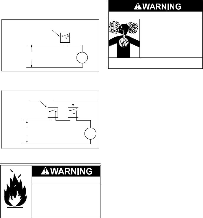
must be periodically oiled. Refer to the pump manufacturer’s instructions for lubrication requirements.
CIRCULATING PUMP WIRING DIAGRAM
STORAGE TANK OR BUILDING RECIRCULATION
FIELD SUPPLIED TEMPERATURE CONTROL INSTALLED IN THE STORAGE TANK
OR CIRCULATING LOOP RETURN LINE
NOTE: USE SEPARATE 120 VAC POWER
SUPPLY FOR PUMP CIRCUIT. DO NOT
SHARE POWER WITH WATER HEATER AS THIS MAY CAUSE ELECTRICAL LINE NOISE AND LEAD TO ERRATIC CONTROL SYSTEM OPERATION.
L1 HOT
120 VAC |
CIRC |
POWER |
PUMP |
|
MOTOR |
L2 NEUTRAL
FIGURE 8.
CIRCULATING PUMP WIRING DIAGRAM
DISHWASHER LOOP WITH TOGGLE SWITCH
DISHWASHER
TOGGLE
SWITCH
NOTE: USE SEPARATE 120 VAC POWER SUPPLY FOR PUMP CIRCUIT. DO NOT SHARE POWER WITH WATER HEATER AS THIS MAY CAUSE ELECTRICAL LINE NOISE AND LEAD TO ERRATIC CONTROL SYSTEM OPERATION.
L1 HOT
120 VAC POWER
L2 NEUTRAL
FIELD SUPPLIED TEMPERATURE CONTROL INSTALLED IN THE CIRCULATING LOOP RETURN LINE
CIRC
PUMP
MOTOR
FIGURE 9.
HIGH ALTITUDE INSTALLATIONS
Fire and Explosion Hazard
 Under no circumstances should the input exceed the rate shown on the water heater’s rating label.
 Overfiring could result in fire or explosion.
 Gas and carbon monoxide detectors are available.
Breathing Hazard - Carbon Monoxide Gas
 Under no circumstances should the input exceed the rate shown on the water heater’s rating label.
 Overfiring could result in damage to the water heater and sooting.
 Gas and carbon monoxide detectors are available.
Breathing carbon monoxide can cause brain damage or death. Always read and understand instruction manual.
Installations above 2000 feet (610 meters) require replacement of burner orifices in accordance with current edition of the National Fuel Gas Code (ANSI Z223.1). For Canadian installations consult Canadian Installations Code CAN/CSA B149.1. Failure to replace orifices will result in improper and inefficient operation of the water heater resulting in the production of increased levels of carbon monoxide gas in excess of safe limits which could result in serious personal injury or death.
You should contact your gas supplier for any specific changes which may be required in your area.
As the elevation above sea level is increased, there is less oxygen per cubic foot of air. Therefore, the heater input rate should be reduced at high altitudes for satisfactory operation with the reduced oxygen supply. Failure to make this reduction would result in an over firing of the heater causing sooting, poor combustion and/or unsatisfactory heater performance.
Ratings specified by manufacturers for most appliances apply for elevations up to 2000 feet (610m). For elevations above 2000 feet (610), ratings must be reduced at the rate of 4% for each 1000 feet (305m) above sea level. For example, if a heater is rated at 78,000 Btuh (22.9 Kwh) at sea level, to rate the heater at 4000 feet (1219m), you subtract 4 (once for each thousand feet) x.04 (4% input reduction) x 78,000 (original rating) from the original rating.
Therefore, to calculate the input rating at 4,000 feet (1219m): 4 x .04 x 78,000 = 12,480 Btuh (3.7 Kwh), 78,000 (22.9 Kwh) - 12,480 (3.7 Kwh) = 65,520 Btuh (19.2 Kwh). At 6000 feet (1829m) the correct input rating should be 59,280 Btuh (17.4 Kwh).
12
INSTALLATION REQUIREMENTS
GAS SUPPLY SYSTEMS
Low pressure building gas supply systems are defined as those systems that cannot under any circumstances exceed 14” W.C. (1/2 PSI Gauge). These systems do not require pressure regulation. Measurements should be taken to insure that gas pressures are stable and fall within the requirements stated on the water heater rating plate. Readings should be taken with all gas burning equipment off (static pressure) and with all gas burning equipment running at maximum rate (dynamic pressure). The gas supply pressure must be stable within 1.5” W.C. from static to dynamic pressure to provide good performance. Pressure drops that exceed 1.5” W.C. may cause rough starting, noisy combustion or nuisance outages. Increases or spikes in static pressure during off cycles may cause failure to ignite or in severe cases damage to appliance gas valves. If your low pressure system does NOT meet these requirements, the installer is responsible for the corrections.
High Pressure building supply systems use pressures that exceed 14” W.C. (1/2 PSI Gauge). These systems must use field supplied regulators to lower the gas pressure to less than 14” W.C. (1/2 PSI Gauge). Water heaters require gas regulators that are properly sized for the water heater input and deliver the rating plate specified pressures. Gas supply systems where pressure exceeds 5 PSI often require multiple regulators to achieve desired pressures. Systems in excess of 5 PSI building pressure should be designed by gas delivery professionals for best performance. Water heaters connected to gas supply systems that exceed 14” W.C. (1/2 PSI Gauge) at any time must be equipped with a gas supply regulator.
All models require a minimum gas supply pressure of 4.5" W.C. for natural gas and 11.0" W.C. for propane gas. The minimum supply pressure is measured while gas is flowing (dynamic pressure). The supply pressure should never fall below 4.5" W.C. for natural gas and 11.0" W.C. for propane gas. The supply pressure should be measured with all gas fired appliances connected to the common main firing at full capacity. If the supply pressure drops more than 1.5” W.C. as gas begins to flow to the water heater then the supply gas system including the gas line and/or the gas regulator may be restricted or undersized. See Supply Gas Regulator section and Gas Piping section of this manual. The gas valve on all models has a maximum gas supply pressure limit of 14” W.C. The maximum supply pressure is measured while gas is not flowing (static pressure).
SUPPLY GAS REGULATOR
The maximum allowable gas supply pressure for this water heater is 14 inches W.C. (3.48 kPa). Install a positive lock-up gas pressure regulator in the gas supply line if inlet gas pressure can exceed 14 inches W.C. (3.48 kPa) at any time. Regulators must be sized/used according to manufacturer’s specifications.
If a positive lock-up regulator is required follow these instructions:
1.Positivelock-upgaspressureregulatorsmustberatedatorabove the input Btu/hr rating of the water heater they supply.
2.Positive lock-up gas pressure regulator(s) should be installed no closer than 3 equivalent feet (1 meter) and no farther than 8 equivalent feet (2.4 meters) from water heater’s inlet gas connection.
3.After installing the positive lock-up gas pressure regulator(s) an initial nominal supply pressure setting of 7.0” W.C. while the water heater is operating is recommended and will generally provide good water heater operation. Some addition adjustment maybe required later to maintain a steady gas supply pressure.
4.When installing multiple water heaters in the same gas supply system it is recommended that individual positive lock-up gas pressure regulators be installed at each unit.
POWER SUPPLY
The water heaters covered in this manual require a 120 VAC,
1Ø (single phase), 60Hz, 15 amp power supply and must also be electrically grounded in accordance with local codes or, in the absence of local codes, with the National Electrical Code, ANSI/ NFPA 70 or the Canadian Electrical Code, CSA C22.1.
WATER TEMPERATURE CONTROL AND MIXING VALVES
Water temperature over 125°F (52°C) can cause severe burns instantly resulting in severe injury or death.
Children, the elderly and the physically or mentally disabled are at highest risk for scald injury.
Feel water before bathing or showering.
Temperature limiting devices such as mixing valves must be installed when required by codes and to ensure safe temperatures at fixtures.
Waterheatedtoatemperaturewhichwillsatisfyclotheswashing,dish washing, and other sanitizing needs can scald and cause permanent injury upon contact. Short repeated heating cycles caused by small hot water uses can cause temperatures at the point of use to exceed the water heater’s temperature setting by up to 20°F (11°C).
Some people are more likely to be permanently injured by hot water than others. These include the elderly, children, the infirm and the physically/mentally disabled. Table 6 shows approximate time-to-burn relationship for normal adult skin. If anyone using hot water provided by the water heater being installed fits into one of these groups or if there is a local code or state law requiring a certain water temperature at the point of use, then special precautions must be taken.
In addition to using the lowest possible temperature setting that satisfies the demand of the application a Mixing Valve should be installed at the water heater (see Figure 10) or at the hot water taps to further reduce system water temperature.
Mixing valves are available at plumbing supply stores. Consult a QualifiedInstallerorServiceAgency.Followmixingvalvemanufacturer’s instructions for installation of the valves.
TABLE 6.
|
Time for 1st Degree Burn |
Time for Permanent Burns |
Water Temperature °F |
(Less Severe Burns) |
2nd & 3rd Degree |
|
|
(Most Severe Burns) |
110 |
(normal shower temp.) |
|
116 |
(pain threshold) |
|
116 |
35 minutes |
45 minutes |
122 |
1 minute |
5 minutes |
131 |
5 seconds |
25 seconds |
140 |
2 seconds |
5 seconds |
149 |
1 second |
2 seconds |
154 |
instantaneous |
1 second |
(U.S. Government Memorandum, C.P.S.C., Peter L. Armstrong, Sept. 15,1978)
13
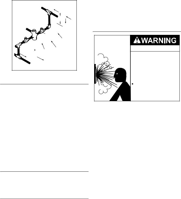
HOT WATER
OUTLET
12” TO 15” (30-38 cm)
TEMPERED WATER
OUTLET
COLD |
|
CHECK |
WATER |
|
VALVE |
INLET |
|
MIXING |
|
CHECK |
|
|
VALVE |
|
|
VALVE |
|
|
|
|
|
TO TANK |
|
|
INLET |
|
FIGURE 10.
DISHWASHING MACHINES
All dishwashing machines meeting the National Sanitation Foundation requirements are designed to operate with water flow pressures between 15 and 25 pounds per square inch (103 kPa and 173 kPa). Flow pressures above 25 pounds per square inch (173 kPa), or below 15 pounds per square inch (103 kPa), will result in improperly sanitized dishes. Where pressures are high, a water pressure reducing or flow regulating control valve should be used in the 180°F (82°C) line to the dishwashing machine and should be adjusted to deliver water pressure between these limits.
The National Sanitation Foundation also recommends circulation of 180°F (82°C) water. The circulation flow rate should be just enough to provide 180°F (82°C) water at the point of take-off to the dishwashing machine.
Adjust flow by throttling a full port ball valve installed in the circulating line on the outlet side of the pump. Never throttle flow on the suction side of a pump. See Water Piping Diagrams in this manual.
NOTE: These water heaters meet the NSF Standard 5 for sanitary installations when used with the leg kit part number
9003425205.
CLOSED WATER SYSTEMS
Water supply systems may, because of code requirements or such conditions as high line pressure, among others, have installed devices such as pressure reducing valves, check valves, and back flow preventers. Devices such as these cause the water system to be a closed system.
THERMAL EXPANSION
As water is heated, it expands (thermal expansion). In a closed system the volume of water will grow when it is heated. As the volume of water grows there will be a corresponding increase in water pressure due to thermal expansion. Thermal expansion can cause premature tank failure (leakage). This type of failure is not covered under the limited warranty. Thermal expansion can also cause intermittent Temperature-Pressure Relief Valve operation: water discharged from the valve due to excessive pressure build up. This condition is not covered under the limited warranty. The Temperature-Pressure Relief Valve is not intended for the constant relief of thermal expansion.
A properly sized thermal expansion tank must be installed on all closed systems to control the harmful effects of thermal expansion. Contact a local plumbing service technician to have a thermal expansion tank installed.
See Water Line Connections on page 21 and the Water Piping Diagrams beginning on page 40.
TEMPERATURE-PRESSURE RELIEF VALVE
Explosion Hazard
 Temperature-Pressure Relief Valve must comply with ANSI Z21.22CSA 4.4 and ASME code.
 Properly sized temperaturepressure relief valve must be installed in opening provided.
Can result in overheating and excessive tank pressure.
 Can cause serious injury or death.
Thiswaterheaterisprovidedwithaproperlyrated/sizedandcertified combination Temperature-Pressure Relief Valve (T&P valve) by the manufacturer. The valve is certified by a nationally recognized testing laboratory that maintains periodic inspection of production of listed equipment of materials as meeting the requirements for
Pressure Relief Valves for Hot Water Supply Systems,ANSI Z21.22
• CSA 4.4, and the code requirements of ASME.
If replaced, the new T&P valve must meet the requirements of local codes, but not less than a combination TemperaturePressure Relief Valve rated/sized and certified as indicated in the above paragraph. The new valve must be marked with a maximum set pressure not to exceed the marked hydrostatic working pressure of the water heater (150 psi = 1,035 kPa) and a discharge capacity not less than the water heater Btu/hr or kW input rate as shown on the water heater’s model rating label.
NOTE: In addition to the factory installed Temperature-Pressure Relief Valve on the water heater, each remote storage tank that maybeinstalledandpipedtoawaterheatingappliancemustalso have its own properly sized, rated and approved TemperaturePressure Relief Valve installed. Call the toll free technical support phone number listed on the back cover of this manual for technical assistance in sizing a Temperature-Pressure Relief Valve for remote storage tanks.
For safe operation of the water heater, the Temperature-Pressure
Relief Valve must not be removed from its designated opening nor plugged. The Temperature-Pressure Relief Valve must be installed directly into the fitting of the water heater designed for the pressure relief valve . Install discharge piping so that any discharge will exit the pipe within 6 inches (15.2 cm) above an adequate floor drain, or external to the building. In cold climates it is recommended that it be terminated at an adequate drain inside the building. Be certain that no contact is made with any live electrical part. The discharge opening must not be blocked or reduced in size under any circumstances. Excessive length, over 30 feet (9.14 m), or use of more than four elbows can cause restriction and reduce the discharge capacity of the valve.
14
No valve or other obstruction is to be placed between the Temperature-Pressure Relief Valve and the tank. Do not connect discharge piping directly to the drain unless a 6” (15.2 cm) air gap is provided. To prevent bodily injury, hazard to life, or property damage, the relief valve must be allowed to discharge water in adequate quantities should circumstances demand. If the discharge pipe is not connected to a drain or other suitable means, the water flow may cause property damage.
CAUTION
Water Damage Hazard
•Temperature-Pressure Relief Valve discharge pipe must terminate at adequate drain.
T&P Valve Discharge Pipe Requirements:
•Shall not be smaller in size than the outlet pipe size of the valve, or have any reducing couplings or other restrictions.
•Shall not be plugged or blocked.
•Shall not be exposed to freezing temperatures.
•Shall be of material listed for hot water distribution.
•Shall be installed so as to allow complete drainage of both the Temperature-Pressure Relief Valve and the discharge pipe.
•Must terminate a maximum of six inches above a floor drain or external to the building. In cold climates, it is recommended that the discharge pipe be terminated at an adequate drain inside the building.
•Shall not have any valve or other obstruction between the pressure relief valve and the drain.

 Burn hazard.
 Hot water discharge.
 Keep clear of TemperaturePressure Relief Valve discharge outlet.
TheTemperature-PressureReliefValvemustbemanuallyoperated at least twice a year. Caution should be taken to ensure that (1) no one is in front of or around the outlet of the Temperature-Pressure
Relief Valve discharge line, and (2) the water manually discharged will not cause any bodily injury or property damage because the water may be extremely hot. If after manually operating the valve, it fails to completely reset and continues to release water, immediately close the cold water inlet to the water heater, follow the draining instructions in this manual, and replace the TemperaturePressure Relief Valve with a properly rated/sized new one.
NOTE: The purpose of a Temperature-Pressure Relief Valve is to prevent excessive temperatures and pressures in the storage tank. The T&P valve is not intended for the constant relief of thermal expansion. A properly sized thermal expansion tank must be installed on all closed systems to control thermal expansion, see Closed Water Systems and Thermal Expansion on page 14.
If you do not understand these instructions or have any questions regarding the Temperature-Pressure Relief Valve call the toll free number listed on the back cover of this manual for technical assistance.
CONTAMINATED AIR
Breathing Hazard - Carbon Monoxide Gas
 Install water heater in accordance with the Instruction Manual and NFPA 54 or CAN/CSA-B149.1.
 To avoid injury, combustion and ventilation air must be taken from outdoors.
 Do not place chemical vapor emitting products near water heater.
Breathing carbon monoxide can cause brain damage or death. Always read and understand instruction manual.
Corrosion of the flue ways and vent system may occur if air for combustion contains certain chemical vapors. Such corrosion may result in failure and risk of asphyxiation.
Combustion air that is contaminated can greatly diminish the life span of the water heater and water heater components such as hot surface igniters and burners. Propellants of aerosol sprays, beauty shop supplies, water softener chemicals and chemicals usedindrycleaningprocessesthatarepresentinthecombustion, ventilation or ambient air can cause such damage.
Do not store products of this sort near the water heater.Air which is brought in contact with the water heater should not contain any of these chemicals. If necessary, uncontaminated air should be obtained from remote or outdoor sources. The limited warranty is voided when failure of water heater is due to a corrosive atmosphere. (See limited warranty for complete terms and conditions).
AIR REQUIREMENTS
Breathing Hazard - Carbon Monoxide Gas
 Install water heater in accordance with the Instruction Manual and NFPA 54 or CAN/CSA-B149.1.
 To avoid injury, combustion and ventilation air must be taken from outdoors.
 Do not place chemical vapor emitting products near water heater.
Breathing carbon monoxide can cause brain damage or death. Always read and understand instruction manual.
For safe operation an adequate supply of fresh uncontaminated air for combustion and ventilation must be provided.
An insufficient supply of air can cause recirculation of combustion products resulting in contamination that may be hazardous to life. Such a condition often will result in a yellow, luminous burner flame, causing sooting of the combustion chamber, burners and flue tubes and creates a risk of asphyxiation.
Do not install the water heater in a confined space unless an adequate supply of air for combustion and ventilation is brought in to that space using the methods described in the Confined Space section that follows.
Never obstruct the flow of ventilation air. If you have any doubts or questions at all, call your gas supplier. Failure to provide the proper amount of combustion air can result in a fire or explosion and cause property damage, serious bodily injury or death.
15

UNCONFINED SPACE
An Unconfined Space is one whose volume IS NOT LESS THAN 50 cubic feet per 1,000 Btu/hr (4.8 cubic meters per kW) of the total input rating of all appliances installed in the space. Rooms communicating directly with the space, in which the appliances are installed, through openings not furnished with doors, are considered a part of the unconfined space.
Makeup air requirements for the operation of exhaust fans, kitchen ventilation systems, clothes dryers and fireplaces shall also be considered in determining the adequacy of a space to provide combustion, ventilation and dilution air.
UNUSUALLY TIGHT CONSTRUCTION
In unconfined spaces in buildings, infiltration may be adequate to provide air for combustion, ventilation and dilution of flue gases. However, in buildings of unusually tight construction (for example, weather stripping, heavily insulated, caulked, vapor barrier, etc.) additional air must be provided using the methods described in the Confined Space section that follows.
CONFINED SPACE
A Confined Space is one whose volume is less than 50 cubic feet per 1,000 Btu/hr (4.8 cubic meters per kW) of the total input rating of all appliances installed in the space.
Openings must be installed to provide fresh air for combustion, ventilation and dilution in confined spaces. The required size for the openings is dependent on the method used to provide fresh air to the confined space and the total Btu/hr input rating of all appliances installed in the space.
DIRECT VENT APPLIANCES
Appliances installed in a Direct Vent configuration that derive all air for combustion from the outdoor atmosphere through sealed intake air piping are not factored in the total appliance input Btu/ hr calculations used to determine the size of openings providing fresh air into confined spaces.
EXHAUST FANS
Where exhaust fans are installed, additional air shall be provided to replace the exhausted air. When an exhaust fan is installed in the same space with a water heater, sufficient openings to provide fresh air must be provided that accommodate the requirements for all appliances in the room and the exhaust fan. Undersized openings will cause air to be drawn into the room throughthewaterheater’sventsystemcausing poor combustion. Sooting, serious damage to the water heater and the risk of fire or explosion may result. It can also create a risk of asphyxiation.
LOUVERS AND GRILLES
The free areas of the fresh air openings in the instructions that follow do not take in to account the presence of louvers, grilles or screens in the openings.
The required size of openings for combustion, ventilation and dilution air shall be based on the “net free area” of each opening. Where the free area through a design of louver or grille or screen is known, it shall be used in calculating the size of opening required to provide the free area specified. Where the louver and grille design and free area are not known, it shall be assumed that wood louvers will have 25% free area and metal louvers and grilles will have 75% free area. Non motorized louvers and grilles shall be fixed in the open position.
VENTING INSTALLATION
VENTING
THE INSTRUCTIONS IN THIS SECTION ON VENTING MUST BE FOLLOWED TO AVOID CHOKED COMBUSTION OR RECIRCULATIONOFFLUEGASES. SUCHCONDITIONSCAUSE SOOTING OR RISKS OF FIREANDASPHYXIATION.
Heater must be protected from freezing downdrafts.
Removeallsootorotherobstructionsfromthechimneythatwillretard a free draft.
TypeBventingisrecommendedwiththeseheaters.Fortypicalventing application see TECHNICAL DATAVENTING on pages 19 and 20.
This water heater must be vented in compliance with all local codes, thecurrentrevisionoftheNationalFuelGasCode(ANSI-Z223.1)and with the Category I Venting Tables.
If any part of the vent system are exposed to ambient temperatures below 40°F it must be insulated to prevent condensation.
•Do not connect the heater to a common vent or chimney with solid fuel burning equipment. This practice is prohibited by many local building codes as is the practice of venting gas fired equipment to the duct work of ventilation systems.
•Whereaseparateventconnectionisnotavailableandtheventpipe from the heater must be connected to a common vent with an oil burning furnace, the vent pipe should enter the smaller common vent or chimney at a point above the large vent pipe.
VENT REDUCER
Model BTR 120 is shipped with a 6" to 5" flue outlet adapter. Models BTR 250, 251 and 275 are shipped with a 8" to 6" flue outlet adapter.
Each adapter fits on top of the installed flue damper. Use only vent reducers supplied with the unit. The venting must comply with the current editions of the NATIONAL FUEL GAS CODE, ANSI Z223.1/
NFPA 54 or NATURAL GAS AND PROPANE INSTALLATION CODE
CAN/CSA-B149.1
FIGURE 11.
FIGURE 12.
16
MULTIPLE HEATER MANIFOLD
Figure 13 and tables on pages 19 and 20 should be used for horizontally manifolding two or more heaters.
FIGURE 13.
FRESH AIR OPENINGS FOR CONFINED SPACES
The following instructions shall be used to calculate the size, number and placement of openings providing fresh air for combustion, ventilation and dilution in confined spaces. The illustrations shown in this section of the manual are a reference for the openings that provide fresh air into confined spaces only. DO NOT refer to these illustrations for the purpose of vent installation. See Venting Installation on page 16 for complete venting installation instructions.
OUTDOOR AIR THROUGH TWO OPENINGS
FIGURE 14.
The confined space shall be provided with two permanent openings, one commencing within 12 inches (300 mm) of the top and one commencing within 12 inches (300 mm) of the bottom of the enclosure. The openings shall communicate directly with the outdoors. See Figure 14.
Each opening shall have a minimum free area of 1 square inch per 4,000 Btu/hr (550 mm2 per kW) of the aggregate input rating of all appliances installed in the enclosure. Each opening shall not be less than 100 square inches (645 cm2).
OUTDOOR AIR THROUGH ONE OPENING
FIGURE 15.
Alternatively a single permanent opening, commencing within 12 inches (300 mm) of the top of the enclosure, shall be provided. See Figure 14. The water heater shall have clearances of at least 1 inch (25 mm) from the sides and back and 6 inches (l50 mm) from the front of the water heater. The opening shall directly communicate with the outdoors or shall communicate through a vertical or horizontal duct to the outdoors or spaces that freely communicate with the outdoors and shall have a minimum free area of the following:
1.1 square inch per 3000 Btu/hr (733 mm2 per kW) of the total input rating of all appliances located in the enclosure, and
2.Not less than the sum of the areas of all vent connectors in the space.
OUTDOOR AIR THROUGH TWO HORIZONTAL DUCTS
FIGURE 16.
The confined space shall be provided with two permanent horizontal ducts, one commencing within 12 inches (300 mm) of the top and one commencing within 12 inches (300 mm) of the bottom of the enclosure. The horizontal ducts shall communicate directly with the outdoors. See Figure 16.
Each duct opening shall have a minimum free area of 1 square inch per 2,000 Btu/hr (1100 mm2 per kW) of the aggregate input rating of all appliances installed in the enclosure.
When ducts are used, they shall be of the same cross sectional area as the free area of the openings to which they connect. The minimum dimension of rectangular air ducts shall be not less than 3 inches.
17
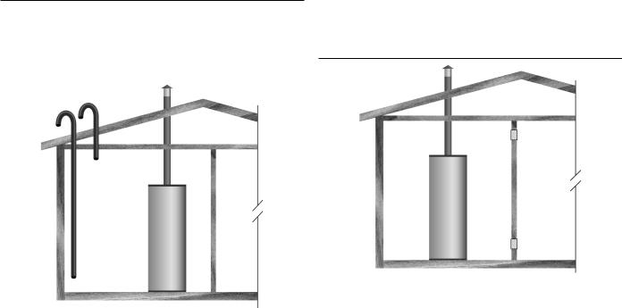
OUTDOOR AIR THROUGH TWO VERTICAL DUCTS
The illustrations shown in this section of the manual are a reference for the openings that provide fresh air into confined spaces only.
DO NOT refer to these illustrations for the purpose of vent installation. See Venting Installation on page 14 for complete venting installation instructions.
FIGURE 17.
The confined space shall be provided with two permanent vertical ducts, one commencing within 12 inches (300 mm) of the top and one commencing within 12 inches (300 mm) of the bottom of the enclosure. The vertical ducts shall communicate directly with the outdoors. See Figure 17.
Each duct opening shall have a minimum free area of 1 square inch per 4,000 Btu/hr (550 mm2 per kW) of the aggregate input rating of all appliances installed in the enclosure.
When ducts are used, they shall be of the same cross sectional area as the free area of the openings to which they connect. The minimum dimension of rectangular air ducts shall be not less than 3 inches.
AIR FROM OTHER INDOOR SPACES
FIGURE 18.
The confined space shall be provided with two permanent openings, one commencing within 12 inches (300 mm) of the top and one commencing within 12 inches (300 mm) of the bottom of the enclosure. See Figure 18.
Each opening shall communicate directly with an additional room(s) of sufficient volume so that the combined volume of all spaces meets the criteria for an Unconfined Space.
Each opening shall have a minimum free area of 1 square inch per 1,000 Btu/hr (2200 mm2 per kW) of the aggregate input rating of all appliances installed in the enclosure. Each opening shall not be less than 100 square inches (645 cm2).
18

TABLE 7. TECHNICAL DATA VENTING
TYPE B GAS VENT
Multiple Gas Fired Tank-Type Heaters
When venting multiple tank type heaters using Type B vent pipe, follow the installation diagram (figure 13) and tables below which give sizing and data based upon NFPA 54/ANSI
Z223. 1992.
MODEL BTR(C)-120 |
|
|
|
|
|
|
|
|
|
|
|
|
|
|
Input: 120,000 Btuh |
|
Total Vent Height (Feet) |
|
|
|
|
|
|
|
|||||
Draft Hood: 5” |
|
|
|
6 |
|
8 |
|
10 |
15 |
20 |
30 |
50 |
100 |
|
|
|
Input Btuh |
Rise |
|
|
|
|
Vent Connector Diameter (inches) |
|
|
||||
|
|
120,000 |
1 Ft. |
|
7 |
|
7 |
|
7 |
6 |
6 |
6 |
6 |
6 |
|
|
120,000 |
2 Ft. |
|
6 |
|
6 |
|
6 |
6 |
6 |
6 |
6 |
5 |
|
|
120,000 |
3 Ft. |
|
6 |
|
6 |
|
6 |
6 |
6 |
5 |
5 |
5 |
Number of |
|
Combined Input in |
|
Manifold and Common Vent Diameter (In inches) |
|
|
||||||||
Heaters |
|
Thousands of Btuh |
|
|
|
|||||||||
|
|
|
|
|
|
|
|
|
|
|
|
|
||
2 |
|
240 |
|
|
10 |
|
8 |
|
8 |
7 |
7 |
7 |
6 |
7 |
3 |
|
360 |
|
|
10 |
|
10 |
|
10 |
10 |
8 |
8 |
7 |
7 |
4 |
|
480 |
|
|
12 |
|
12 |
|
12 |
10 |
10 |
10 |
8 |
8 |
MODEL BTR(C)-154 |
|
|
|
|
|
|
|
|
|
|
|
|
|
|
Input: 154,000 Btuh |
|
|
|
Total Vent Height (Feet) |
|
|
|
|
|
|||||
Draft Hood: 6” |
|
|
|
6 |
|
8 |
|
10 |
15 |
20 |
30 |
50 |
100 |
|
|
|
Input Btuh |
Rise |
|
|
Vent Connector Diameter (in inches) |
|
|
||||||
|
|
154,000 |
1 Ft. |
|
8 |
|
8 |
|
7 |
7 |
7 |
7 |
7 |
7 |
|
|
154,000 |
2 Ft. |
|
7 |
|
7 |
|
7 |
7 |
7 |
6 |
6 |
6 |
|
|
154,000 |
3 Ft. |
|
7 |
|
7 |
|
7 |
6 |
6 |
6 |
6 |
6 |
Numbers of |
|
Combined Input in |
|
Manifold and Common Vent Diameter (in inches) |
|
|
||||||||
Heaters |
|
Thousands of Btuh |
|
|
|
|||||||||
|
|
|
|
|
|
|
|
|
|
|
|
|
||
2 |
|
308 |
|
|
10 |
|
10 |
|
10 |
8 |
8 |
7 |
7 |
7 |
3 |
|
462 |
|
|
12 |
|
12 |
|
12 |
10 |
10 |
10 |
8 |
8 |
4 |
|
616 |
|
|
14 |
|
14 |
|
12 |
12 |
12 |
10 |
1 |
10 |
|
|
|
|
|
|
|
|
|
|
|
|
|
|
|
MODEL BTR(C)-180, 197, 198, 199, |
200 |
|
|
|
|
|
|
|
|
|
|
|
|
|
Input: 180,000, 199,000 Btuh |
|
|
Total Vent Height (Feet) |
|
|
|
|
|
|
|
||||
Draft Hood: 6” |
|
|
|
6 |
|
8 |
|
10 |
15 |
20 |
30 |
50 |
100 |
|
|
|
Input Btuh |
Rise |
|
|
Vent Connector Diameter (in inches) |
|
|
||||||
|
|
180,000 |
1 Ft. |
|
8 |
|
8 |
|
8 |
8 |
8 |
7 |
7 |
7 |
|
|
199,000 |
|
|
- |
|
- |
|
8 |
8 |
8 |
8 |
8 |
7 |
|
|
180,000 |
2 Ft. |
|
8 |
|
8 |
|
7 |
7 |
7 |
7 |
7 |
7 |
|
|
199,000 |
|
|
8 |
|
8 |
|
8 |
8 |
7 |
7 |
7 |
7 |
|
|
180,000 |
3 Ft. |
|
7 |
|
7 |
|
7 |
7 |
7 |
7 |
6 |
6 |
|
|
199,000 |
|
|
8 |
|
8 |
|
7 |
7 |
7 |
7 |
7 |
6 |
Number of |
|
Combined Input in |
|
|
|
|
Manifold & Common Vent Diameter |
|
|
|||||
Heaters |
|
Thousands of Btuh |
|
|
|
|
|
|
||||||
|
|
|
|
|
|
|
|
|
|
|
|
|
||
2 |
|
360 |
|
|
10 |
|
10 |
|
10 |
10 |
8 |
8 |
7 |
7 |
|
398 |
|
|
12 |
|
10 |
|
10 |
10 |
10 |
8 |
8 |
7 |
|
|
|
|
|
|
|
|||||||||
3 |
|
540 |
|
|
14 |
|
12 |
|
12 |
12 |
10 |
10 |
10 |
8 |
|
597 |
|
|
14 |
|
14 |
|
12 |
12 |
12 |
10 |
10 |
10 |
|
|
|
|
|
|
|
|||||||||
4 |
|
720 |
|
|
14 |
|
14 |
|
14 |
12 |
12 |
12 |
10 |
10 |
|
796 |
|
|
16 |
|
14 |
|
14 |
14 |
12 |
12 |
12 |
10 |
|
|
|
|
|
|
|
|||||||||
19

20
MECHANICAL VENTING
SINGLE UNIT INSTALLATION
When mechanical venting of these heaters is desired, the following kits are available.
Models 120 through the 200/A
A. O. Smith part number 9005381205
Models 250/A through the 400/A
A. O. Smith part number 9003434205
Where an approved power venter is to be installed to operate in conjunction with the water heater thermostat, the following codes must be adhered to. Field wiring should conform to the current edition of the National Electrical Code NFPA 70. For Canadian installations the electrical connections and grounding shall be done in accordance with the current edition of the Canadian Electrical Code CSAC22.1 and/or local codes.
VENT INSTALLATION
Seal all joints between the power venter and the vent termination. This is to prevent leakage of exhaust products into the room(s) due to positive pressure of blower.
The “Sequence of Operation” description will be the same with mechanical venting except;
When the water heater thermostat calls for heat:
Thermostat contacts “Close” and the power venter blower (120 VAC) is energized. Sufficient draft must be established for the “Draft Prover Switch (N.O.)” to “Close”. When the draft prover switch “Closes” the relay coil of the flue damper is energized.
MULTIPLE UNIT INSTALLATION
For multiple unit installations, contact A. O. Smith, Technical Support Center at 1-800-527-1953.
WATER HEATER INSTALLATION
WATER LINE CONNECTIONS
The water piping installation must conform to these instructions and to all local code authority having jurisdiction. Good practice requires that all heavy piping be supported.
Read and observe all requirements in the following sections before installation of the water piping begins:
WATER PIPING DIAGRAMS
This manual provides detailed water piping diagrams for typical methods of application for the water heaters, see Water Piping Diagrams beginning on page 40.
The water heater may be installed by itself, or with a separate storage tank. When used with a separate storage tank, the circulation may be either by gravity or by means of circulating
1.Water Temperature Control and Mixing Valves on page 13. pump. Adjust flow by throttling a full port ball valve installed in the
2.Dishwashing Machines on page 14.
3.Temperature-Pressure Relief Valve on page 14-15.
circulating line on the outlet side of the pump. Never throttle flow on the suction side of a pump. See the Water Piping Diagrams beginning on page 40.
4.Closed Systems and Thermal Expansion on page 14. NOTE: In addition to the factory installed Temperature-Pressure
5.For multiple water heater installations see Water Piping
Diagrams beginning on page 40.
WATER (POTABLE) HEATING AND SPACE HEATING
1.All piping components connected to this unit for space heating applications shall be suitable for use with potable water.
2.Toxic chemicals, such as those used for boiler treatment, shall NEVER be introduced into this system.
3.This unit may NEVER be connected to any existing heating system or component(s) previously used with a non-potable water heating appliance.
4.When the system requires water for space heating at temperatures higher than required for domestic water purposes, a tempering valve must be installed. Please refer to installation diagrams beginning on page 40 of this manual for suggested piping arrangements.
5.These water heaters cannot be used in space heating applications only
THERMOMETERS (NOT SUPPLIED)
Thermometers should be obtained and field installed as shown in the installation diagrams.
Thermometers are installed in the system as a means of detecting the temperature of the outlet water supply.
Relief Valve (T&P valve) on the water heater, each remote storage tank that may be installed and piped to a water heating appliance must also have its own properly sized, rated and approved Temperature-Pressure Relief Valve installed.
Call the toll free technical support phone number listed on the back cover of this manual for further assistance in sizing a T&P valve for remote storage tanks.
T&P VALVE DISCHARGE PIPE
Explosion Hazard
 Temperature-Pressure Relief Valve must comply with ANSI Z21.22CSA 4.4 and ASME code.
 Properly sized temperaturepressure relief valve must be installed in opening provided.
Can result in overheating and excessive tank pressure.
 Can cause serious injury or death.
21

This water heater is provided with a properly rated/sized and certified combination temperature - pressure (T&P) relief valve by themanufacturer.SeeTemperature-PressureReliefValveonpages 14-15 for information on replacement and other requirements.
CAUTION
Water Damage Hazard
•Temperature-Pressure Relief Valve discharge pipe must terminate at adequate drain.
Install a discharge pipe between the T&P valve discharge opening and a suitable floor drain. Do not connect discharge piping directly to the drain unless a 6” (15.2 cm) air gap is provided. To prevent bodily injury, hazard to life, or property damage, the relief valve must be allowed to discharge water in adequate quantities should circumstances demand. If the discharge pipe is not connected to a drain or other suitable means, the water flow may cause property damage.
T&P VALVE DISCHARGE PIPE REQUIREMENTS:
•Shall not be smaller in size than the outlet pipe size of the valve, or have any reducing couplings or other restrictions.
•Shall not be plugged or blocked.
•Shall not be exposed to freezing temperatures.
•Shall be of material listed for hot water distribution.
•Shall be installed so as to allow complete drainage of both Temperature-Pressure Relief Valve and the discharge pipe.
•Must terminate a maximum of six inches above a floor drain or external to the building. In cold climates, it is recommended that the discharge pipe be terminated at an adequate drain inside the building.
•Shall not have any valve or other obstruction between the relief valve and the drain.
INSTALLATION DIAGRAMS - TOP INLET/OUTLET USAGE
Use of the top inlet water connection requires an inlet dip tube (refer to figure 19). The tube is supplied in the heater. Follow caution labels if applying heat to this fitting. Do not allow pipe dope to contact the plastic tube during installation.
TUBE INLET INSTALLATION
FIGURE 19.
22
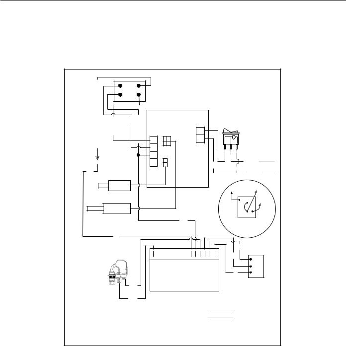
HEATER WIRING
All electrical work must be installed in accordance with the current edition of the National Electrical Code ANSI/NFPA No. 70 or Canadian Electrical
Code CSAC22.1 and must conform to all local code authority having jurisdiction. AN ELECTRICAL GROUND IS REQUIRED TO REDUCE RISK OF ELECTRICAL SHOCK OR POSSIBLE ELECTROCUTION.
If any of the original wire as supplied with the water heater must be replaced, use only type 105°C thermoplastic or equivalent 2500C type F must be used for the flame sensor and igniter leads.
The controls of this water heater are polarity sensitive. Be certain to properly wire the hot and neutral connections.
24VA |
|
1 |
3 |
|
|
|
|
||
C |
|
4 |
2 |
|
TO |
|
DAMPER DRIVE |
|
NEUTRAL24 |
CONTROLIGNITION |
24VA |
|
||
|
|
BLK |
|
|
|
C |
|
|
|
|
Y |
|
|
|
RLOWER PROBE
UPPER
PROBE/ECO
R
LEGEND:
W--WHITE
BLK--BLACK BL--BLUE
R--RED W Y--YELLOW
BL
DAMPER
DRIVE
|
|
11E79 |
LINE |
|
ON/OFF |
|
|
|
|
|
|
|
|
|
|||
|
|
|
IN |
|
|
|
||
|
|
|
|
SWITCH |
|
|
||
|
|
|
|
|
|
|
||
|
4 |
|
|
|
|
X |
|
|
|
|
|
|
|
|
|
|
|
|
3 |
|
|
|
|
|
|
|
|
2 |
|
|
BLK |
BLK |
|
|
|
|
|
|
|
|
|
120 vac |
||
|
1 |
|
|
|
|
|
||
|
|
|
W |
|
|
|
||
|
|
|
|
|
W |
|
||
|
|
|
|
|
|
NEUTRAL |
||
|
|
|
|
|
|
|
|
|
|
|
|
|
|
|
PV |
|
MV/PV |
|
|
|
|
|
|
|
|
|
|
|
|
|
|
|
|
PV |
MV |
|
|
|
|
|
|
|
|
|
|
|
|
|
|
|
|
|
MV |
|
|
|
|
|
|
|
|
TH TR |
|
|
|
W |
|
|
|
PROPANE |
|
|
|
|
|
|
|
|
GAS |
|
|
|
|
|
|
|
|
VALVE |
|
|
|
|
D |
|
|
|
BL |
|
|
|
|
|
|
|
BLK |
|
C |
SPARKER |
|
|
MV MV/PV PV BURNER-GND GNV24 V24 |
|
|
|
||
|
|
|
Y |
|
P |
|||
|
|
|
|
|
|
|
||
|
|
|
|
|
|
|
M |
|
|
|
|
|
|
|
|
|
NATURAL |
|
|
|
|
|
|
|
|
GAS |
|
|
HONEYWELL IGNITION |
|
|
|
|
VALVE |
|
FACTORY WIRED
BY INSTALLER
IF ANY OF THE ORIGINAL WIRE AS SUPPLIED MUST BE REPLACED, USE ONLY TYPE 105O C THERMOPLASTIC OR EQUIVALENT. FLAME SENSOR IGNITION CABLE MUST BE 250O C TYPE F.
197287-000 REV 02
FIGURE 20.
23
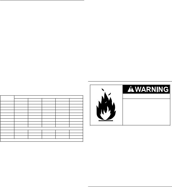
GAS PIPING
Contact your local gas service company to ensure that adequate gas service is available and to review applicable installation codes for your area.
Size the main gas line in accordance with Table 8. The figures shown are for straight lengths of pipe at 0.5 in. W.C. pressure drop, which is considered normal for low pressure systems. Note: Fittings such as elbows, tees and line regulators will add to the pipe pressure drop. Also refer to the latest version of the National Fuel Gas Code.
Schedule 40 Steel or Wrought Iron Pipe is the preferred material for the gas line of this water heater. It is imperative to follow the sizing recommendations in the latest version of the National Fuel
Gas Code if Corrugated Stainless Steel Tubing (CSST) is used as the gas line for this water heater.
The heater is not intended for operation at higher than 14.0" W.C.- natural gas, (1/2 pound per square inch gage) supply gas pressure. Exposure to higher supply pressure may cause damage to the gas valve which could result in fire or explosion. If overpressure has occurred such as through improper testing of gas lines or emergency malfunction of the supply system, the gas valve must be checked for safe operation. Make sure that the outside vents on the supply regulators and the safety vent valves are protected against blockage. These are parts of the gas supply system, not the heater. Vent blockage may occur during ice storms.
TABLE 8. GAS SUPPLY PIPE LENGTHS (IN FEET) Maximum Equivalent Pipe Length - Natural Gas Only
Input rate |
|
Schedule 40 Steel or Wrought Iron Pipe |
|
||
(BTU/HR) |
1/2" |
3/4" |
1" |
1 1/4" |
1 1/2" |
120,000 |
20 |
70 |
200 |
200 |
200 |
154,000 |
10 |
40 |
150 |
200 |
200 |
180,000 |
- |
30 |
100 |
200 |
200 |
199,000 |
- |
30 |
90 |
200 |
200 |
250,000 |
- |
20 |
60 |
200 |
200 |
275,000 |
- |
10 |
50 |
200 |
200 |
310,000 |
- |
10 |
40 |
150 |
200 |
366,000 |
- |
- |
30 |
100 |
200 |
390,000 |
- |
- |
20 |
100 |
200 |
Fitting Type* |
|
Equivalent length in feet |
|
||
45°Ell |
0.7 |
1.0 |
1.2 |
1.6 |
1.9 |
90°Ell |
1.6 |
2.1 |
2.6 |
3.5 |
4.0 |
Tee |
3.1 |
4.1 |
5.2 |
6.9 |
8.0 |
Natural Gas 0.60 Specific Gravity, 0.50" W.C. Pressure Drop |
|
||||
*Screwed Fittings |
|
|
|
|
|
It is important to guard against gas valve fouling from contaminants in gas ways. Such fouling may cause improper operation, fire or explosion.
If copper supply lines are used they must be internally tinned and certified for gas service. Before attaching the gas line, be sure that all gas pipe is clean on the inside.
To trap any dirt or foreign material in the gas supply line, a sediment trap must be incorporated in the piping (see Figure 21).The sediment trapmustbereadilyaccessibleandnotsubjecttofreezingconditions. Install in accordance with recommendations of serving gas suppliers. Refer to the latest version of the National Fuel Gas Code.
To prevent damage, care must be taken not to apply too much torque when attaching gas supply pipe to gas valve inlet.
Apply joint compounds (pipe dope) sparingly and only to the male threadsofpipejoints.Donotapplycompoundstothefirsttwothreads. Use compounds resistant to the action of liquefied petroleum gases.
GAS METER SIZE – NATURAL GASES ONLY
Be sure the gas meter has sufficient capacity to supply the full rated gas input of the water heater as well as the requirements of all other gasfiredequipmentsuppliedbythemeter.Ifgasmeteristoosmall,ask the gas company to install a larger meter having adequate capacity.
GAS PIPING AND SEDIMENT TRAP INSTALLATION
FIGURE 21.
GAS LINE LEAK TESTING
Fire and Explosion Hazard
 Use joint compound or Teflon tape compatible with propane gas.
 Leak test before placing the water heater in operation.
 Disconnect gas piping and main gas shutoff valve before leak testing.
 Install sediment trap in accordance with NFPA 54.
Any time work is done on the gas supply system perform a leak test to avoid the possibility of fire or explosion.
1.For test pressures exceeding 1/2 psi (3.45 kPa) disconnect the water heater and its Main Gas Shutoff Valve from the gas supply piping system during testing, see Figure 21. The gas supply line must be capped when disconnected from the water heater.
2.For test pressures of 1/2 psi (3.45 kpa) or less, the water heater need not be disconnected, but must be isolated from the supply gas line by closing the Main Gas Shutoff Valve during testing.
3.Coat all supply gas line joints and connections upstream of the water heater with a non-corrosive soap and water solution to test for leaks. Bubbles indicate a gas leak. Do not use matches, candles, flame or other sources of ignition for this purpose.
4.Repair any leaks before placing the water heater in operation.
PURGING
Gas line purging is required with new piping or systems in which air has entered.
Purging should be performed per the current edition of NFPA 54 the National Fuel Gas Code.
24
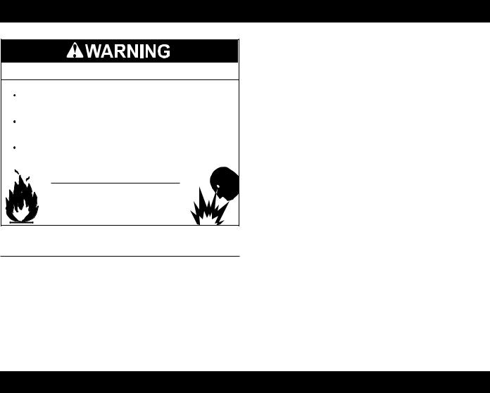
OPERATION
Fire or Explosion Hazard
Gas line purging is required with new piping or systems in which air has entered.
To avoid risk of fire or explosion purge discharge must not enter into confined areas or spaces where ignition can occur.
The area must be well ventilated and all sources of ignition must be deactivated or removed.
Read instruction manual before installing, using or servicing water heater.
PRIOR TO START UP
Installation and start up of this water heater requires abilities and skills equivalent to that of a licensed tradesman in the field involved, see Qualifications on page 6.
Do not place the water heater in operation if any part has been under water. Immediately call a qualified service technician to inspect the water heater and to replace any part of the control system and any gas control which has been under water.
Light the water heater in accordance with the Lighting and Operation Instruction label on the water heater and in this manual on pages 27 and 28.
The water heaters covered by this manual are equipped with an electronic control system that automatically sequences the Igniter, the 24 VAC Gas Valve, the Burner ignition, and flame sensing.
Before attempting start up, thoroughly study and know the exact Sequence Of Operation. See written Sequence Of Operation on page 25 and Sequence Of Operation Flow Chart on page 26.
Be certain that the water heater is full of water, that air is purged from the gas and water lines and that there are no leaks in the gas and water lines. Ensure all inlet water valves are open.
FILLING THE WATER HEATER
Follow these steps to fill the water heater prior to start up.
1.Close the heater drain valve.
2.Open a nearby hot water faucet to permit air in system to escape.
3.Fully open the cold water inlet valve allowing the piping and water heater to fill with water.
4.Close hot water faucet opened in Step 2 as water starts to flow.
Read SEQUENCE OF OPERATION section of this manual prior to lighting and operating this water heater.
With above conditions satisfied, start the unit in accordance with the instructions on the operating label attached to the heater. For your convenience a copy of the instructions are shown on pages 27 and 28.
SEQUENCE OF OPERATION
The following information will describe the Sequence of Operation for this water heater.
1.Switch power on to unit.
2.Thermostat calls for heat.
3.Ignition Control performs diagnostic self check on system components.
4.The Ignition Control begins the trial for ignition.
5.TheIgnitionControlturnsontheSparkIgniterandopensthePilot Gas Valve.
6.TheIgnitionControlmonitorstheFlameSensorduringtheignition trial period.
7.If the Ignition Control does not sense the pilot flame during the ignition trial period, the Ignition Control shuts the Pilot Gas
Valve and turns off the Spark Igniter. Depending on the water heater model, the Ignition Control will either retry the ignition trial at step 4 or lockout the ignition sequence. If the ignition sequence
is locked out, the power to the unit must be cycled to restart the Ignition Control.
8.If the pilot flame is proved during the ignition trial period, the
Ignition Control turns off the Spark Ignitor and opens the Main
Gas Valve.
9.The Ignition Control allows a 2 second pilot flame stabilization period to insure that the pilot flame is not extinguished by the main burner light-off process.
10.The Ignition Control monitors the Flame Sensor during the heating cycle. If the flame signal is lost, the Ignition Control shuts the Main Gas Valve and Pilot Gas Valve and re-starts the ignition process at step 4.
11.Once the unit is satisfied, the Ignition Control will shut off the Main Gas Valve and the Pilot Gas Valve and the unit will be in
standby mode until another call for heat is initiated by the thermostat.
See the flow chart on page 26 for more information.
25
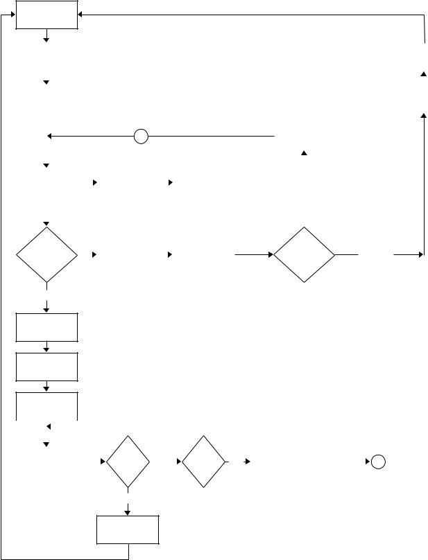
SEQUENCE OF OPERATION FLOW CHART
Description of this flow chart can be found in the “SEQUENCE OF OPERATION” section found on page 25.
IDLE
(NOT POWERED)
“CALL FOR HEAT” |
|
|
|
|
|
|
|
|
|
|
|
WAIT FOR |
||
RECEIVED FROM |
|
|
|
|
|
|
|
|
|
|
|
“CALL FOR HEAT” |
||
THERMOSTAT |
|
|
|
|
|
|
|
|
|
|
|
TO BE REMOVED |
||
|
|
|
|
|
|
|
|
|
|
|
|
|
|
|
|
|
|
|
|
|
|
|
|
|
|
|
|
|
|
POWER TO |
|
|
|
|
|
|
|
|
|
|
|
ACTIVATE |
ALARM |
|
MODULE AND |
|
|
|
|
|
|
|
|
|
|
|
CONTACT(S) |
||
SELF CHECK |
|
|
|
|
|
|
|
|
|
|
|
(OPTIONAL) |
||
|
|
|
|
|
|
|
|
|
|
|
|
|
|
|
|
|
|
|
A |
|
|
|
|
|
RETRY DELAY |
|
|
|
|
|
|
|
|
|
|
|
|
|
(5 MINUTES) |
|
|
|
||
|
|
|
|
|
|
|
|
|
|
|
|
|||
|
|
|
|
|
|
|
|
|
|
|
|
|
|
|
|
|
|
|
|
|
|
|
|
|
|
|
|
|
|
|
|
|
|
|
|
|
|
|
|
|
|
|
|
|
|
|
|
|
|
|
|
|
|
|
|
|
|
|
|
TRIAL FOR |
|
|
|
|
|
OPEN PILOT GAS |
|
|
|
|
|
|
||
IGNITION |
|
|
SPARK ON |
|
|
|
|
|
|
|
|
|||
|
|
|
|
VALVE |
|
|
|
|
|
|
||||
(TIMER STARTED) |
|
|
|
|
|
|
RETRY |
|||||||
|
|
|
|
|
|
|
|
|||||||
|
|
|
|
|
|
|
|
|
|
|
|
|
|
|
|
|
|
|
|
|
|
|
|
|
|
|
|
|
|
|
|
|
|
|
|
|
|
|
|
|
|
|
|
|
FLAME |
|
NO |
|
|
CLOSE PILOT |
|
|
SPARK OFF |
RETRY OR |
LOCKOUT |
PROVED? |
|
|
|
|
|
LOCKOUT |
||||
|
|
|
|
|||||||
|
|
|
|
GAS VALVE |
|
|
|
|
||
|
|
|
|
|
|
|
|
|
MODEL? |
|
(BEFORE TRIAL FOR IGNITION TIMER EXPIRES)
YES
SPARK OFF
OPEN MAIN GAS
VALVE
FLAME
STABILIZATION (2 SECONDS)
|
|
|
|
|
|
|
NO |
|
|
|
|
|
|
|
|
|
|
|
|
“CALL |
|
|
|
|
|
|
|
|
|
||
|
|
|
|
|
|
|
|
|
|
|
|
|
|
|
|
|
|
|
|
|
|
|
|
|
|
|
|
|
|
|
|
|
|
|
|
|
|
|
|
|
|
|
|
|
|
|
|
|
|
|
|
|
|
|
|
|
FLAME |
|
CLOSE MAIN GAS |
|
|
||
RUN |
|
FOR HEAT” |
|
NO |
|
|
YES |
VALVE AND PILOT |
|
A |
|||||
|
|
|
|
LOST? |
|
||||||||||
|
|
|
|
ENDS? |
|
|
|
|
|
|
GAS VALVE |
|
|
||
|
|
|
|
|
|
|
|
|
|
|
|
|
|
||
YES
CLOSE MAIN GAS
VALVE AND PILOT
GAS VALVE
FLOW CHART 1.
26
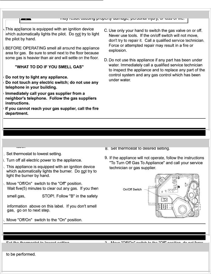
LIGHTING & OPERATION LABEL
FOR YOUR SAFETY READ BEFORE OPERATING
OPERATING INSTRUCTIONS
FOR YOUR SAFETY READ BEFORE OPERATING
FIGURE 22. LABEL FOR NATURAL GAS MODELS
27
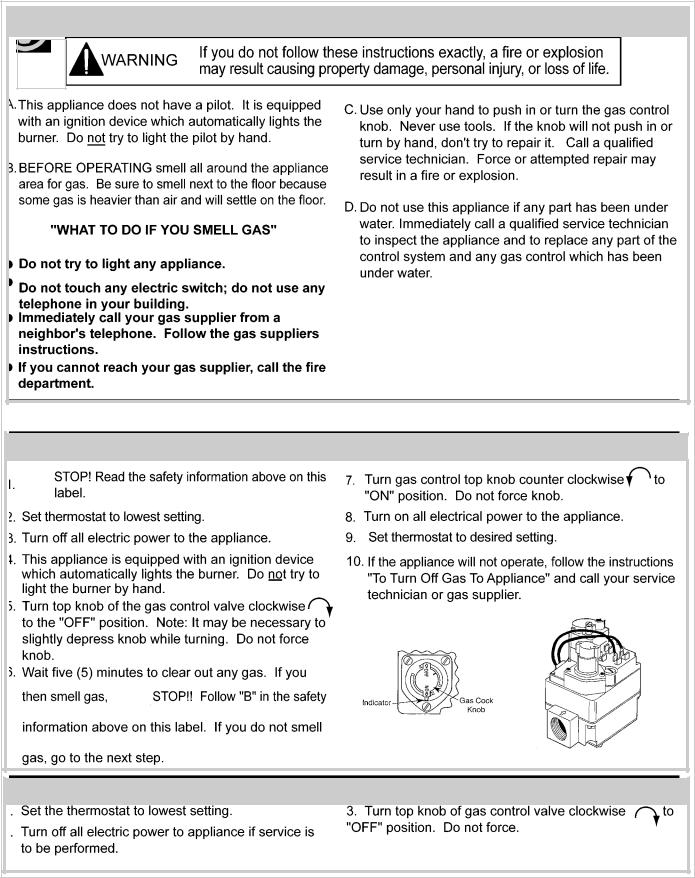
FOR YOUR SAFETY READ BEFORE OPERATING
OPERATING INSTRUCTIONS
TO TURN OFF GAS TO APPLIANCE
FIGURE 23. LABEL FOR PROPANE GAS MODELS
28

ADJUSTMENTS
ON INITIALSTARTUPSOMEADJUSTMENTS MAYBE NECESSARY.
Check Manifold and inlet gas pressures (see GAS SUPPLY SYSTEMSonpage13andCHECKINGTHEINPUTonpage29-30.)
Check Pilot Burner (See Pilot Burner section on page 34.)
TESTING DAMPER OPERATION
With the Service Switch in the AUTOMATIC OPERATION position, check the operation of the flue damper three (3) times with the water operating controls for proper operating sequence:
•The damper disc must be open (in the vertical position) before the ignition and combustion process begins.
•The damper disc must be in the open position when the main burner is firing.
•The gas control valve must close and the main burner must have ceased firing before the damper disc begins its return to the closed (horizontal) position.
If during testing of the operation of the damper you find that there is a problem with the operation of the water heater when the Service Switch is in the AUTOMATIC OPERATION position: Reset the Service Switch to the HOLD OPEN DAMPER position and check operation again.
If the water heater does operate when placed in the HOLD OPEN DAMPER position:
•Refer to the EFFIKALRVGP-FSF-SERIES TROUBLESHOOTING GUIDE on page 37.
If the water heater does not operate with the Service Switch in either position:
•Refer to the Troubleshooting Sections and Troubleshooting Checklist.
CHECKING VENTING
Thefollowingstepsshallbefollowedwitheachapplianceconnected totheventingsystemplacedinoperation,whileanyotherappliances connected to the venting system are not in operation.
1.Seal any unused openings in the venting system.
2.Inspecttheventingsystemforpropersizeandhorizontalpitch,as requiredintheNationalFuelGasCode,ANSIZ223.1ortheCAN/ CGAB149InstallationCodesandtheseinstructions. Determine that there is no blockage or restriction, leakage, corrosion and other deficiencies which could cause an unsafe condition.
3.So far as is practical, close all building doors and windows and all doors between the space in which the water heater(s) connected to the venting system are located and other spaces of the building. Turn on all appliances not connected to the venting system.Turn on all exhaust fans, such as range hoods and bathroom exhausts, so they shall operate at maximum speed. Close fireplace dampers.
4.Follow the lighting instruction. Place the water heater being inspected in operation.Adjust thermostat so water heater shall operate continuously.
5.Test for draft hood spillage at the relief opening after 5 minutes of main burner operation.
6.After it has been determined that each appliance connected to theventingsystemproperlyventswhentestedasoutlinedabove, returndoors,windows,exhaustfans,fireplacedampersandany other gas burning appliance to their previous conditions of use.
7.If improper venting is observed during any of the above tests, the venting system must be corrected.
FAILURE TO CORRECT BACK DRAFTS MAY CAUSE AIR CONTAMINATION AND UNSAFE CONDITIONS.
•If the back draft cannot be corrected by the normal method or if a suitable draft cannot be obtained, a blower type flue gas exhauster must be employed to assure proper venting and correct combustion.
CHECKING THE INPUT
For installation locations with elevations above 2000 feet, refer to HIGH ALTITUDE INSTALLATIONS section of this manual for input reduction procedure.
1.Attach a pressure gauge or a manometer to the manifold pressure tap on the gas control valve and refer to Table 9, for correct manifold pressure.
2.Use this formula to “clock” the meter. Be sure that other gas consuming appliances are not operating during this interval.
(3600/T) x H = Btuh
T = Time in seconds to burn one cubic foot of gas. H = Btu’s per cubic foot of gas.
Btuh = Actual heater input. Example: (Using BTR-250 heater) T = 15.1 seconds
H = 1050 Btu Btuh = ?
(3600/15.1) x 1050 = 250,000 (Compare with BTR-250 model and rating.)
TABLE 9.
APPROXIMATE TIME REQUIRED TO CONSUME 1 CU. FT. OF GAS AT FULL CAPACITY
INPUT |
TYPE |
BTUH |
TIME REQ’D TO |
|
RATE |
OF |
PER |
CONSUME 1 CU. |
|
(BTUH) |
GAS |
CU. FT. |
FT. OF GAS |
|
120,000 |
NATURAL |
1050 |
31. 5 SEC. |
|
PROPANE |
2500 |
75.0 SEC. |
||
|
||||
154,000 |
NATURAL |
1050 |
24.5 SEC. |
|
PROPANE |
2500 |
58.4 SEC. |
||
|
||||
180,000 |
NATURAL |
1050 |
21.0 SEC. |
|
PROPANE |
2500 |
50.0 SEC. |
||
|
||||
199,000 |
NATURAL |
1050 |
19.0 SEC. |
|
PROPANE |
2500 |
45.2 SEC. |
||
|
||||
250,000 |
NATURAL |
1050 |
15.1 SEC. |
|
PROPANE |
2500 |
36.0 SEC. |
||
|
||||
251,000 |
NATURAL |
1050 |
15.1 SEC. |
|
PROPANE |
2500 |
35.9 SEC. |
||
|
||||
275,000 |
NATURAL |
1050 |
13.7 SEC. |
|
PROPANE |
2500 |
32.7 SEC. |
||
|
||||
|
|
|
|
|
305,000 |
NATURAL |
1050 |
12.4 SEC. |
|
PROPANE |
2500 |
29.5 SEC. |
||
|
||||
|
|
|
|
|
365,000 |
NATURAL |
1050 |
10.4 SEC. |
|
PROPANE |
2500 |
24.7 SEC. |
||
|
||||
|
|
|
|
|
390,000 |
NATURAL |
1050 |
9.7 SEC. |
|
PROPANE |
2500 |
23.1 SEC. |
||
|
||||
|
|
|
|
29
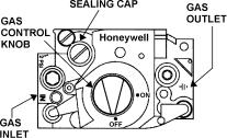
Should it be necessary to adjust the gas pressure to the burners to obtain the full input rate, the steps below should be followed:
3.Remove the regulator adjustment sealing cap and adjust the pressure by turning the adjusting screw with a screwdriver. See Figure 24.
 Clockwise to increase gas pressure and input rate.
  Counterclockwisetodecreasegaspressureandinputrate.
4.“Clock” the meter as in step 2 above.
5.Repeat steps 3 and 4 until the specified input rate is achieved.
6.Turn the gas control knob to PILOT. Remove the pressure gauge and replace the sealing cap and the Allen wrench set screw in the pressure tap opening.
FIGURE 24.
UNDER NO CIRCUMSTANCES SHOULD THE GAS INPUT EXCEED THE INPUT SHOWN ON THE HEATER MODEL AND RATING
PLATE. OVERFIRING COULD RESULT IN DAMAGE OR SOOTING OF THE HEATER.
30
 Loading...