

ANRITSU MU196020A, PAM4 PPG, MU196040A, PAM4 ED, MU196040B Operation Manual

MU196020A
Operation Manual
●
For safety and warning information, please read this
●
Additional safety and warning information is provided
before using
●
PAM4 PPG
MU196040A
PAM4 ED
MU196040B
PAM4 ED
Sixth Edition
manual before attempting to use the equipment.
within the MP1900A Signal Quality Analyzer-R
Operation Manual. Please also refer to it
the equipment.
Keep this manual with the equipment.
ANRITSU CORPORATION
Document No.: M-W3976AE-6.0
Safety Symbols
DANGER
WARNING
CAUTION
To prevent the risk of personal injury or loss related to equipment malfunction, Anritsu Corporation uses the
following safety symbols to indicate safety-related information. Ensure that you clearly understand the meanings of
the symbols BEFORE using the equipment. Some or all of the following symbols may be used on all Anritsu
equipment. In addition, there may be other labels attached to products that are not shown in the diagrams in this
manual.
Symbols used in manual
This indicates a very dangerous procedure that could result in serious injury or
death if not performed properly.
This indicates a hazardous procedure that could result in serious injury or death if
not performed properly.
This indicates a hazardous procedure or danger that could result in light-to-severe
injury, or loss related to equipment malfunction, if proper precautions are not taken.
Safety Symbols Used on Equipment and in Manual
The following safety symbols are used inside or on the equipment near operation locations to provide information
about safety items and operation precautions. Ensure that you clearly understand the meanings of the symbols and
take the necessary precautions BEFORE using the equipment.
This indicates an obligatory safety precaution. The obligatory operation is
This indicates a warning or caution. The contents are indicated symbolically in or
This indicates a note. The contents are described in the box.
These indicate that the marked part should be recycled.
This indicates a prohibited operation. The prohibited operation is indicated
symbolically in or near the barred circle.
indicated symbolically in or near the circle.
near the triangle.
MU196020A PAM4 PPG
MU196040A PAM4 ED
MU196040B PAM4 ED
Operation Manual
1 December 2018 (First Edition)
30 September 2020 (Sixth Edition)
Copyright © 2018-2020, ANRITSU CORPORATION.
All rights reserved. No part of this manual may be reproduced without the prior written permission of the
publisher.
The operational instructions of this manual may be changed without prior notice.
Printed in Japan
ii

Equipment Certificate
Anritsu Corporation certifies that this equipment was tested before shipment
using calibrated measuring instruments with direct traceability to public
testing organizations recognized by national research laboratories, including
the National Institute of Advanced Industrial Science and Technology, and
the National Institute of Information and Communications Technology, and
was found to meet the published specifications.
Anritsu Warranty
Anritsu Corporation will repair this equipment free-of-charge if a malfunction
occurs within one year after shipment due to a manufacturing fault, and
software bug fixes will be performed in accordance with the separate
Software End-User License Agreement, provide, however, that Anritsu
Corporation will deem this warranty void when:
●
The fault is outside the scope of the warranty conditions separately
described in the operation manual.
●
The fault is due to mishandling, misuse, or unauthorized modification or
repair of the equipment by the customer.
●
The fault is due to severe usage clearly exceeding normal usage.
●
The fault is due to improper or insufficient maintenance by the customer.
●
The fault is due to natural disaster, including fire, wind or flood,
earthquake, lightning strike, or volcanic ash, etc.
●
The fault is due to damage caused by acts of destruction, including civil
disturbance, riot, or war, etc.
●
The fault is due to explosion, accident, or breakdown of any other
machinery, facility, or plant, etc.
●
The fault is due to use of non-specified peripheral or applied equipment
or parts, or consumables, etc.
●
The fault is due to use of a non-specified power supply or in a
non-specified installation location.
●
The fault is due to use in unusual environments
●
The fault is due to activities or ingress of living organisms, such as
insects, spiders, fungus, pollen, or seeds.
In addition, this warranty is valid only for the original equipment purchaser. It
is not transferable if the equipment is resold.
Anritsu Corporation shall assume no liability for damage or financial loss of
the customer due to the use of or a failure to use this equipment, unless the
damage or loss is caused due to Anritsu Corporation’s intentional or gross
negligence.
(Note)
.
iii

Note:
For the purpose of this Warranty, "unusual environments" means use:
●
In places of direct sunlight
●
In dusty places
●
Outdoors
●
In liquids, such as water, oil, or organic solvents, and medical fluids, or
places where these liquids may adhere
●
In salty air or in place chemically active gases (sulfur dioxide, hydrogen
sulfide, chlorine, ammonia, nitrogen dioxide, or hydrogen chloride etc.)
are present
●
In places where high-intensity static electric charges or electromagnetic
fields are present
●
In places where abnormal power voltages (high or low) or instantaneous
power failures occur
●
In places where condensation occurs
●
In the presence of lubricating oil mists
●
In places at an altitude of more than 2,000 m
●
In the presence of frequent vibration or mechanical shock, such as in
cars, ships, or airplanes
Anritsu Corporation Contact
In the event of this equipment malfunctions, please contact an Anritsu
Service and Sales office. Contact information can be found on the last page
of the printed version of this manual, and is available in a separate file on the
PDF version.
iv

This product and its manuals may require an Export License/Approval by
the Government of the product's country of origin for re
country.
Before re-exporting the product or manuals, please contact us to confirm
whether
When you dispose of export
to be broken/shredded so as not to be unlawfully used for military
purpose.
Notes On Export Management
-export from your
they are export-controlled items or not.
-controlled items, the products/manuals need
v

Crossed-out Wheeled Bin Symbol
Equipment marked with the Crossed-out Wheeled Bin Symbol complies with
council directive 2012/19/EU (the “WEEE Directive”) in European Union.
For Products placed on the EU market after August 13, 2005, please contact
your local Anritsu representative at the end of the product's useful life to
arrange disposal in accordance with your initial contract and the local law.
vi

Software End-User License Agreement (EULA)
Please carefully read and accept this Software End-User License Agreement (hereafter this EULA)
before using (includes executing, copying, installing, registering, etc.) this Software (includes programs,
databases, scenarios, etc., used to operate, set, etc., Anritsu electronic equipment, etc.). By using this
Software, you shall be deemed to have agreed to be bound by the terms of this EULA, and Anritsu
Corporation (hereafter Anritsu) hereby grants you the right to use this Software with the Anritsu
specified equipment (hereafter Equipment) for the purposes set out in this EULA.
Article 1. Grant of License and Limitations
1. You may not to sell, transfer, rent, lease,
lend, disclose, sublicense, or otherwise
distribute this Software to third parties,
whether or not paid therefor.
2. You may make one copy of this Software for
backup purposes only.
3. You are not permitted to reverse engineer,
disassemble, decompile, modify or create
derivative works of this Software.
4. This EULA allows you to install one copy of
this Software on one piece of Equipment.
Article 2. Disclaimers
To the extent not prohibited by law, in no
event shall Anritsu be liable for direct, or
any incidental, special, indirect or
consequential damages whatsoever,
including, without limitation, damages for
loss of profits, loss of data, business
interruption or any other commercial
damages or losses, and damages claimed by
third parties, arising out of or related to your
use or inability to use this Software, unless
the damages are caused due to Anritsu’s
intentional or gross negligence.
Article 3. Limitation of Liability
1. If a fault (bug) is discovered in this Software,
failing this Software to operate as described
in the operation manual or specifications
even though you have used this Software as
described in the manual, Anritsu shall at its
own discretion, fix the bug, or replace the
software, or suggest a workaround,
free-of-charge, provided, however, that the
faults caused by the following items and any
of your lost or damaged data whatsoever
shall be excluded from repair and the
warranty.
i) If this Software is deemed to be used
for purposes not described in the
operation manual or specifications.
ii) If this Software has been used in
conjunction with other
non-Anritsu-approved software.
iii) If this Software or the Equipment has
been modified, repaired, or otherwise
altered without Anritsu's prior
approval.
iv) For any other reasons out of Anritsu's
direct control and responsibility, such
as but not limited to, natural disasters,
software virus infections, or any
devices other than this Equipment, etc.
2. Expenses incurred for transport, hotel, daily
allowance, etc., for on-site repairs or
replacement by Anritsu engineers
necessitated by the above faults shall be
borne by you.
3. The warranty period for faults listed in
Section 1 of this Article shall be either 6
months from the date of purchase of this
Software or 30 days after the date of repair
or replacement, whichever is longer.
vii

Article 4. Export Restrictions
You shall not use or otherwise export or
re-export directly or indirectly this Software
except as authorized by the laws and
regulations of Japan and the United States,
etc. In particular, this Software shall not be
exported or re-exported (a) into any Japan or
US embargoed countries or (b) to anyone
restricted by the Japanese export control
regulations, or the US Treasury
Department's list of Specially Designated
Nationals or the US Department of
Commerce Denied Persons List or Entity
List. In using this Software, you warrant
that you are not located in any such
embargoed countries or on any such lists.
You also agree that you will not use or
otherwise export or re-export this Software
for any purposes prohibited by the Japanese
and US laws and regulations, including,
without limitation, the development, design
and manufacture or production of missiles or
nuclear, chemical or biological weapons of
mass destruction, and conventional
weapons.
Article 5. Change of Terms
Anritsu may change without your approval
the terms of this EULA if the changes are for
the benefit of general customers, or are
reasonable in light of the purpose of this
EULA and circumstances of the changes. At
the time of change, Anritsu will inform you
of those changes and its effective date, as a
general rule 45
website, or in writing or by e-mail.
days, in advance on its
Article 6. Termination
1. Anritsu may terminate this EULA
immediately if you violate any conditions
described herein. This EULA shall also be
terminated immediately by Anritsu if there
is any good reason that it is deemed difficult
to continue this EULA, such as your
violation of Anritsu copyrights, patents, etc.
or any laws and ordinances, or if it turns out
that you belong to an antisocial organization
or has a socially inappropriate relationship
with members of such organization.
2. Yo u and Anritsu may terminate this EULA
by a written notice to the other party 30
days in advance.
Article 7. Damages
If Anritsu suffers any damages or loss,
financial or otherwise, due to your violation
of the terms of this EULA, Anritsu shall
have the right to seek proportional damages
from you.
Article 8. Responsibility after Termination
Upon termination of this EULA in
accordance with Article 6, you shall cease all
uses of this Software immediately and shall
as directed by Anritsu either destroy or
return this Software and any backup copies,
full or partial, to Anritsu.
Article 9. Negotiation for Dispute
Resolution
If matters of interpretational dispute or
items not covered under this EULA arise,
they shall be resolved by negotiations in
good faith between you and Anritsu.
Article 10. Governing Law and Court of
Jurisdiction
This EULA shall be governed by and
interpreted in accordance with the laws of
Japan without regard to the principles of the
conflict of laws thereof, and any disputes
arising from or in relation to this EULA that
cannot be resolved by negotiation described
in Article 9 shall be subject to and be settled
by the exclusive agreed jurisdiction of the
Tokyo District Court of Japan.
Revision History:
February 29th, 2020
viii

CE Conformity Marking
Anritsu affixes the CE conformity marking on the following product(s) in
accordance with the Decision 768/2008/EC to indicate that they conform to
the EMC, LVD and RoHS directive of the European Union (EU).
CE marking
1. Product Model
Plug-in Units: MU196020A PAM4 PPG
MU196040A PAM4 ED
MU196040B PAM4 ED
2. Applied Directive and Standards
When the MU196020A PAM4 PPG, MU196040A PAM4 ED and
MU196040B PAM4 ED are installed in the MP1900A, the applied directive
and standards of this unit conform to those of the MP1900A main frame.
PS: About main frame
Please contact Anritsu for the latest information on the main frame
types that MU196020A, MU196040A and MU196040B can be used
with.
ix

RCM Conformity Marking
Anritsu affixes the RCM mark on the following product(s) in accordance with
the regulation to indicate that they conform to the EMC framework of
Australia/New Zealand.
RCM marking
1. Product Model
Plug-in Units: MU196020A PAM4 PPG
MU196040A PAM4 ED
MU196040B PAM4 ED
2. Applied Directive and Standards
When the MU196020A PAM4 PPG, MU196040A PAM4 ED and
MU196040B PAM4 ED are installed in the MP1900A, the applied directive
and standards of this unit conform to those of the MP1900A main frame.
PS: About main frame
Please contact Anritsu for the latest information on the main frame
types that MU196020A, MU196040A and MU196040B can be used
with.
x
Configuration of Signal Quality Analyzer-R Series Operation
Describes the basic operations, panel details, and maintenance of the MP1900A, as
well as the steps from module installation to the start of use.
indicates this document.
Describes the panel details, how to operate, performance test, maintenance, and
troubleshooting of the
Operation Manual
Describes the panel details, how to operate, performance test, maintenance, and
troubleshooting of the MU181000A
Describes the panel details, how to operate, performance test and maintenance of the
MU181500B.
Describes the panel details, how to operate, performance test, maintenance, and
Operation Manual
Describes the panel details, performance test, maintenance, and troubleshooting of
Describes the panel details, performance test, maintenance, and troubleshooting of
the
About This Manual
A testing system combining an MP1900A Signal Quality Analyzer-R,
module(s), and control software is called a Signal Quality Analyzer-R
Series. The operation manuals of the Signal Quality Analyzer-R Series
consist of separate documents for the MP1900A, module(s), and control
software, as shown below.
MP1900A Signal Quality Analyzer-R Operation Manual
Module Operation Manual
MU195020A 21G/32G bit/s SI PPG MU195040A 21G/32G bit/s SI ED
MU195050A Noise Generator Operation Manual
module to be installed on the MP1900A.
MU196020A PAM4 PPG MU196040A PAM4 ED MU196040B PAM4 ED
Operation Manual
MU196020A, MU196040A, and MU196040B.
MU181000A 12.5GHz Synthesizer MU181000B 12.5GHz 4 port Synthesizer
and MU181000B.
MU181500B Jitter Modulation Source Operation Manual
MU183020A 28G/32G bit/s PPG MU183021A 28G/32G bit/s 4ch PPG
the MU183020A and MU183021A.
MU183040A 28G/32G bit/s ED MU183041A 28G/32G bit/s 4ch ED
MU183040B 28G/32G bit/s High Sensitivity ED
MU183041B 28G/32G bit/s 4ch High Sensitivity ED Operation Manual
troubleshooting of the MU183040A, MU183041A, MU183040B, and MU183041B.
I

Describes the setup and operating procedure of MX183000A.
Describes the operation of the extended application for the Signal Quality Analyzer-R
Series.
Configuration of Signal Quality Analyzer-R Series Operation Manuals (Cont’d)
indicates this document.
MX190000A Signal Quality Analyzer-R Control Software Operation Manual
Describes the operation of the software that controls the Signal Quality Analyzer-R
Series
.
Extended Application Operation Manual
MX183000A High-Speed Serial Data Test Software Operation Manual
II

2 3 4
Table of Contents
1
About This Manual ................................................. I
Chapter 1
1.1 Product Overview........................................................ 1-2
1.2 Product Configuration ................................................. 1-4
1.3 Specifications.............................................................. 1-9
Chapter 2
2.1 Installation to MP1900A .............................................. 2-2
2.2 How to Operate Application ......................................... 2-2
2.3 Preventing Damage .................................................... 2-3
Chapter 3
3.1 Panel Layout ............................................................... 3-2
3.2 Inter-Module Connection ............................................. 3-5
Overview ............................................ 1-1
Before Use ......................................... 2-1
Panel Layout and Connectors......... 3-1
5
6
Chapter 4
4.1 Evaluating Optical Components in 400GbE
4.2 Evaluating Devices for 400GbE Transceiver ................ 4-5
Usage Examples ............................... 4-1
Transceiver ................................................................. 4-2
Chapter 5 Performance Test ............................. 5-1
5.1 Timing of Performance Tests ...................................... 5-2
5.2 Devices Required for Performance Tests .................... 5-3
5.3 Performance Test Items .............................................. 5-5
Chapter 6
6.1 Daily Maintenance ...................................................... 6-2
6.2 Cautions on Storage ................................................... 6-2
6.3 Transportation............................................................. 6-3
6.4 Calibration .................................................................. 6-3
Maintenance ...................................... 6-1
7
Appendix
Index
III

Chapter 7
7.1 Problems That Occur When Replacing Modules .......... 7-2
7.2 Problems That Occur During Output Waveform
7.3 Problems That Occur During Error Rate Measurement 7-4
7.4 Synchronization Failures ............................................. 7-5
Troubleshooting ............................... 7-1
Observation ................................................................ 7-3
Appendix A Pseudo-Random Pattern ............. A-1
Appendix B List of Default Settings ................ B-1
Appendix C Performance Test Record Sheet
....................................................... C-1
Index ................................................... Index-1
IV.

Overview
Overview
This chapter describes the overview of the following modules.
● MU196020A PAM4 PPG (hereafter, MU196020A)
● MU196040A PAM4 ED (hereafter, MU196040A)
● MU196040B PAM4 ED (hereafter, MU196040B)
1.1
Product Overview........................................................ 1-2
1.2 Product Configuration ................................................. 1-4
1.2.1 Standard configuration .................................... 1-4
1.2.2 Options ........................................................... 1-5
1.2.3 Optional Accessories....................................... 1-7
1.3 Specifications.............................................................. 1-9
1.3.1 Specifications for MU196020A ........................ 1-9
1.3.2 Specifications for MU196040A ...................... 1-42
1.3.3 Specifications for MU196040B ...................... 1-58
1
1-1

Chapter 1 Overview
1.1 Product Overview
The MU196020A, MU196040A, and MU196040B (hereinafter “MP1900A
modules”) are plug-in modules that can be built into the MP1900A Signal
Quality Analyzer-R. MP1900A supports error measurement with PRBS
patterns, DATA patterns and various PAM4 test patterns at the following
bit rates or baud rates:
MU196020A: Max. 64.2 Gbit/s or 64.2 Gbaud
•
MU196040A: Max. 32.1 Gbit/s or 32.1 Gbaud
•
MU196040B: Max. 64.2 Gbit/s or 58.2 Gbaud
•
Combination of MU196020A and MU195050A Noise Generator
(hereinafter, MU195050A) supports generation of data which common
mode noise, differential mode noise and white noise are applied to and
which is optimal for signal integrity evaluation of up to 32.1 Gbaud.
Various option configurations are available for the MP1900A modules.
This module is therefore useful for research, development, and production
of various types of digital communication equipment, modules, and
devices.
The features of the MP1900A modules are as follows:
MU196020A features
Capable of generating one channel of NRZ or PAM4 signal at up to 64.2
•
Gbit/s or 64.2 Gbaud. (MU196020A-003)
Capable of independently adjusting the amplitude of each eye of PAM4
•
signal.
Capable of generating signals of PRBS pattern, DATA pattern and
•
various PAM4 patterns.
Capable of signal integrity evaluation using 4TAP Emphasis
•
(MU196020A-x11)
Capable of adding intersymbol interference (ISI) using 4TAP Emphasis.
•
(MU196020A-x40)
Capable of generating patterns and inserting errors, which support
•
RS-FEC(544,514) and RS-FEC(528,514). (MU196020A-x42)
Capable of synchronizing operations among channels using multiple
•
MU196020As that are installed in MP1900A.
This function allows generating synchronous data supported by the
application that requires Multi Channel. (MU196020A-x50)
1-2

Overview
1.1 Product Overview
MU196040A features
Supporting symbol measurement of one channel of PAM4 signal at up
•
to 32.1 Gbaud using the built-in PAM4 Decoder circuit.
Capable of measuring signals of PRBS pattern, DATA pattern and
•
various PAM4 patterns.
Long user-programmable patterns (256 Mbits, 256 Msymbol)
•
Capable of evaluating serial communication by selecting
•
MU196040A-001 that has one data input channel each for NRZ (32.1
Gbit/s) and PAM4 (32.1 Gbaud).
Having the input sensitivity (typical values) of NRZ 23 mV (32.1 Gbit/s,
•
Eye Height) and PAM4 23 mV (32.1 Gbaud, Eye Height, per eye) and
optimal for signal evaluation.
Capable of clock recovery on 25.5 to 32.1 Gbaud signals by installing
•
MU196040A-x22.
Capable of evaluating PAM4 signals by Symbol Error Rate (SER) by
•
installing MU196040A-x41.
MU196040B features
Supporting symbol measurement of one channel of PAM4 signal at up
•
to 58.2 Gbaud using the built-in PAM4 Decoder circuit.
Capable of measuring signals of PRBS pattern, DATA pattern and
•
various PAM4 patterns.
Long user-programmable patterns (256 Mbits, 256 Msymbols)
•
Capable of capturing the data pattern of up to 8 Mbits or 4 Msymbols.
•
Capable of capturing the data pattern, in which RS-FEC Symbol
•
Error(s) occurred, and counting FEC Symbol Errors.
Capable of evaluating serial communication by selecting
•
MU196040B-002 or x12 that has one data input channel each for NRZ
(64.2 Gbit/s) and PAM4 (58.2 Gbaud).
Having the input sensitivity (typical values) of NRZ 23 mV (32.1 Gbit/s,
•
Eye Height) and PAM4 23 mV (32.1 Gbaud, Eye Height, per eye) and
optimal for signal evaluation.
Capable of using the Equalizer function by adding the
•
MU196040B-x11.
Capable of clock recovery on 2.4 to 29.0 Gbaud signals by installing
•
MU196040B-x21.
Capable of clock recovery on 2.4 to 32.1 Gbaud signals by installing
•
MU196040B-x22.
Capable of clock recovery on 51.0 to 58.2 Gbaud signals by installing
•
MU196040B-x23.
Capable of evaluating PAM4 signals by Symbol Error Rate (SER) by
•
installing MU196040B-x41.
1
1-3
Mainframe
MU196020A
PAM4 PPG
1
Accessories
J1632A
Terminator
4
Clock Output,
Gating Output
V210
Terminator
2
Data Output × 2
J1341A
Open
2
Ext Clock Input,
AUX Input
J1359A
Coaxial Adaptor (K-P.K-J, SMA)
1
Clock Output
J1717A
Coaxial Adaptor (SMA-P, SAM-J)
5
Ext Clock Input,
Mainframe
MU196040A
PAM4 ED
1
Accessories
J1632A
Terminator
2
Aux Output × 2,
J1341A
Open
2
Ext Clock Input,
AUX Input
J1359A
Coaxial Adaptor (K-P.K-J, SMA)
1
Ext Clock Input
J1717A
Coaxial Adaptor (SMA-P, SAM-J)
3
Aux Output × 2,
AUX Input
When the MU196040A-001 is installed:
J1341A
Open
2
Data Input × 2
J1359A
Coaxial Adaptor (K-P.K-J, SMA)
2
Data Input × 2
Mainframe
MU196040B
PAM4 ED
1 Accessories
V210
Terminator
2
Data Input × 2
J1341A
Open
2
Ext Clock Input,
AUX Input
J1359A
Coaxial Adaptor (K-P.K-J, SMA)
1
Ext Clock Input
J1632A
Terminator
2
Aux Output × 2,
J1717A
Coaxial Adaptor (SMA-P, SAM-J)
3
Aux Output × 2,
41V-6
Precision Fixed Attenuator
2
Data Input × 2
Chapter 1 Overview
1.2 Product Configuration
1.2.1 Standard configuration
Table 1.2.1-1 and Table 1.2.1-2 below show the standard configurations of
the three MP1900A modules respectively.
Table 1.2.1-1 Standard Configuration of MU196020A
Item Model Name Product Name Q'ty Remarks
Aux Output × 2,
Aux Output × 2,
Gating Output,
AUX Input
Table 1.2.1-2 Standard Configuration of MU196040A
Item Model Name Product Name Q'ty Remarks
Table 1.2.1-3 Standard Configuration of MU196040B
Item Model Name Product Name Q'ty Remarks
1-4
AUX Input
Overview
1.2.2 Options
MU196020A-001
32G baud
*1
MU196020A-002
58G baud
*
MU196020A-003
64G baud
*1
MU196020A-y12
32G to 58G baud Extension Retrofit
*2,*
MU196020A-y13
32G to 64G baud Extension Retrofit
*2,*3
MU196020A-y23
58G to 64G baud Extension Retrofit
*2,*4
MU196020A-x11
4Tap Emphasis
*5
MU196020A-x30
Data Delay
*5
MU196020A-x40
Adjustable ISI
*
MU196020A-x42
FEC Pattern Generation
*5
MU196020A-x50
Inter-Module Synchronization
*
Indicates function.
Anritsu management number.
MU196020A-x x x
1.2 Product Configuration
Table 1.2.2-1 and Table 1.2.2-2 show the options for the MP1900A
modules. All options are sold separately.
Note:
Option name format is as follows:
This value is recognized by the MP1900A.
This value is not recognized by the mainframe.
0: Factory-installed option
1: Retrofit option.
(Must be returned to Anritsu (Japan) when
installing.)
2: Retrofit option.
(Must be returned to Anritsu Service and
Sales office when installing.)
3: Software option.
License registration is required when
installing
1
Model Name Product Name Remarks
Table 1.2.2-1 Options of MU196020A
1
3
5, *6
5, *7
*1: Factory-installed hardware option. Select one from among them.
*2: Hardware retrofit options, which can be selected after shipping from
our factory. (y = 1 or 2)
*3: It can be retrofitted when the Option 001 is installed.
*4: It can be retrofitted when the Option 002 is installed.
1-5
MU196040A-001
32.1G baud Decoder
*1
MU196040A-x22
25.5G to 32.1G baud Clock Recovery
*2,*
MU196040A-x41
SER Measurement
*2,*4
MU196040B-001
32G baud
*1,*2
MU196040B-002
58G baud
*1,*2 MU196040B-z11
Equalizer
*2,*11
MU196040B-y12
32G to 58G baud Extension
*2,*5,*6
MU196040B-x21
29G baud Clock Recovery
*3,*4,*7,*8
MU196040B-x22
32G baud Clock Recovery
*3,*4,*7,*8
MU196040B-x23
58G baud Clock Recovery Extension
*2,*4,*9
MU196040B-y24
32G baud Clock Recovery Extension
*3,*5,*10
MU196040B-z41
SER Measurement
*2,*11
Chapter 1 Overview
Model Name Product Name Remarks
*5: Software option (x = 0, 1, or 2)
*6: It can be retrofitted when the Option x11 is installed.
*7: It can be retrofitted when the Option x30 is installed.
Table 1.2.2-2 Options of MU196040A
3
*1: Factory-installed hardware option
*2: x = 0, 1, or 2
*3: Hardware option
*4: Software option
Table 1.2.2-3 Options of MU196040B
Model Name Product Name Remarks
*1: Factory-installed
*2: Software option
*3: Hardware option
*4: x = 0, 1, or 2
*5: y = 1 or 2
*6: MU196040B-001 must be installed.
1-6
*7: This option can be installed together with MU196040B-x23.
*8: One of MU196040B-x21 and MU196040B-x22 can be installed.
*9: MU196040B-002 or MU196040B-y12 must be installed.
MU196040B-x21 or MU196040B-x22 must be installed.
*10: MU196040B-x21 must be installed.
*11: z = 0, 1, 2, or 3

Overview
1.2.3 Optional Accessories
34VFK50
Precision Adapter
Conversion connector (V-F K-M)
34VKF50
Precision Adapter
Conversion connector (V-M K-F)
41KC-3
Precision Fixed Attenuator 3 dB
K connector
41KC-6
Precision Fixed Attenuator 6 dB
K connector
41KC-10
Precision Fixed Attenuator 10 dB
K connector
41KC-20
Precision Fixed Attenuator 20 dB
K connector
41V-3
Precision Fixed Attenuator 3 dB
V connector
41V-6
Precision Fixed Attenuator 6 dB
V connector
41V-10
Precision Fixed Attenuator 10 dB
V connector
41V-20
Precision Fixed Attenuator 20 dB
V connector
J1342A
Coaxial Cable 0.8 m
APC3.5 connector
J1359A
Coaxial Adaptor (K-P.K-J, SMA)
J1439A
Coaxial Cable 0.8 m (K connector)
J1510A
Pick OFF Tee
K connector
J1624A
Coaxial Cable 0.3 m (SMA connector)
J1625A
Coaxial Cable 1 m (SMA connector)
J1632A
Terminator
SMA connector
J1678A
ESD Protection Adapter-K
K connector
J1679A
ESD Protection Adapter-V
V connector
J1728A
Electrical Length Specified Coaxial Cable
(0.4 m, K connector)
1.2 Product Configuration
Table 1.2.3-1 shows the optional accessories for the MP1900A modules.
All optional accessories are sold separately.
Table 1.2.3-1 Optional Accessories
Model Name Product Name Remarks
1
1-7

J1748A
Power Splitter (1.5G-18GHz)
J1758A
ISI Board
J1789A
Electrical Length Specified Coaxial Cable
(0.4m, V connector)
J1790A
Electrical Length Specified Coaxial Cable
(0.8m, V connector)
J1792A
Skew match pair semirigid cable
(V-K connector, Data Input1)
For connecting to the Data
Input1 connector of MU195050A
J1793A
Pick OFF Tee
V connector
J1800A
ISI Board V
V connector
K240C
Precision Power Divider
K connector
V210
Terminator
V connector
V240C
Precision Power Divider
V connector
W3976AE
MU196020A/40A/40B Operation Manual
Printed version, English
Z0306A
Wrist strap
Z1964A
Torque Wrench (Right Angle)
Chapter 1 Overview
Table 1.2.3-1 Optional Accessories (Cont’d)
Model Name Product Name Remarks
1-8

Overview
1.3 Specifications
Operating Baud/Bit Rate
When the Option 001 is installed.
output) is common. Only the baud rate is described hereafter.
Setting Range / Step
The setting range of the baud rate is determined by the linking module
When linking with
2.400 000 to 25.000 000 Gbaud, 0.000 002 Gbaud step*1, *2, *3
50.000 008 to 64.200 000 Gbaud, 0.000 008 Gbaud step*3
When linking with
2.400 000 to 3.125 000 Gbaud, 0.000 002 Gbaud step*1, *2, *3
51.200 008 to 64.200 000 Gbaud, 0.000 008 Gbaud step*3
1.3.1 Specifications for MU196020A
Table 1.3.1-1 Operating Baud/Bit Rate
Item Specifications
PAM4: 2.4 to 32.1 Gbaud
NRZ: 2.4 to 32.1 Gbit/s
When the Option 002 or y12 is installed.
PAM4: 2.4 to 58.2 Gbaud
NRZ: 2.4 to 58.2 Gbit/s
When the Option 003, y13, or y23 is installed.
PAM4: 2.4 to 64.2 Gbaud
NRZ: 2.4 to 64.2 Gbit/s
The setting range of the baud rate (PAM4 output) and bit rate (NRZ
1.3 Specifications
1
MU181000A/B *4
MU181000A/B and
MU181500B *
4
(valid only when installing to the same frame as MU196020A) and the
Frequency in
25.000 004 to 32.100 000 Gbaud, 0.000 004 Gbaud step*1, *2, *3
25.000 004 to 50.000 000 Gbaud, 0.000 004 Gbaud step*
50.000 008 to 58.200 000 Gbaud, 0.000 008 Gbaud step*
3.200 002 to 6.250 000 Gbaud, 0.000 002 Gbaud step*1, *2, *3
6.400 002 to 12.500 000 Gbaud, 0.000 002 Gbaud step*
12.800 002 to 25.000 000 Gbaud, 0.000 002 Gbaud step*
25.600 004 to 32.100 000 Gbaud, 0.000 004 Gbaud step*
25.600 004 to 50.000 000 Gbaud, 0.000 004 Gbaud step*
51.200 008 to 58.200 000 Gbaud, 0.000 008 Gbaud step*
*1: When the Option 001 is installed.
*2: When the Option 002 or y12 is installed.
*3: When the Option 003, y13, or y23 is installed.
Linking is not available when Unit Sync is ON.
*4:
Table 1.3.1-12 Clock Output.
2, *3
2
1, *2, *3
1, *2, *3
1, *2, *3
2, *3
2
1-9
When linking with
external clock
Clock Output Rate Full
Clock Output Rate Half
2.4 to 15.0 Gbaud*1,*2,*3
2.4 to 15.0 GHz
1/1 Clock Input
15.0 to 30.0 Gbaud*1,*2,*3
7.5 to 15.0 GHz
1/2 Clock Input
25.0 to 32.1 Gbaud*1,*2,*3
6.25 to 8.025 GHz
1/4 Clock Input
2.4 to 30.0 Gbaud*1,*2,*3
1.2 to 15.0 GHz
1/2 Clock Input
30.0 to 32.1 Gbaud*1
7.5 to 8.025 GHz
1/4 Clock Input
30.0 to 58.2 Gbaud*2
7.5 to 14.55 GHz
1/4 Clock Input
30.0 to 60.0 Gbaud*3
7.5 to 15.0 GHz
1/4 Clock Input
60.0 to 64.2 Gbaud*3
7.5 to 8.025 GHz
1/8 Clock Input
Chapter 1 Overview
Item Specifications
MU181500B and using
Table 1.3.1-1 Operating Baud/Bit Rate (Cont'd)
Rate
Rate, Quarter Rate
Baud Rate Setting Range
Baud Rate Setting Range
Input Clock
Frequency
Input Clock
Frequency
Relationship
Between Baud
Rate and Input
Clock Frequency
Relationship
Between Baud
Rate and Input
Clock Frequency
1-10
Overview
Table 1.3.1-1 Operating Baud/Bit Rate (Cont'd)
External Clock
When the Output Clock
When the Output Clock
Offset Setting Range / Step
–1000 to +1000 ppm, 1 ppm step
25.000 000 Gbaud, 50.000 000 Gbaud
2.4 to 16.05 Gbaud*1,*2,*3
2.4 to 16.05 GHz
1/1 Clock Input
16.05 to 32.1 Gbaud*1,*2,*3
8.025 to 16.05 GHz
1/2 Clock Input
25.0 to 32.1 Gbaud*1,*2,*3
6.25 to 8.025 GHz
1/4 Clock Input
2.4 to 32.1 Gbaud*1,*2,*3
1.2 to 16.05 GHz
1/2 Clock Input
25.0 to 32.1 Gbaud*1
6.25 to 8.025 GHz
1/4 Clock Input
25.0 to 50.0 Gbaud*2,*3
6.25 to 12.50 GHz
1/4 Clock Input
32.1 to 58.2 Gbaud*2
8.025 to 14.55 GHz
1/4 Clock Input
32.1 to 64.2 Gbaud*3
8.025 to 16.05 GHz
1/4 Clock Input
50.0 to 58.2 Gbaud*2
6.25 to 7.275 GHz
1/8 Clock Input
50.0 to 64.2 Gbaud*3
6.25 to 8.025 GHz
1/8 Clock Input
1.3 Specifications
Item Specifications
Rate is set to Full Rate
Rate is set to Half Rate,
Quarter Rate
Baud Rate Setting
Range
Baud Rate Setting
Range
Input Clock
Frequency
Input Clock
Frequency
Relationship
Between Baud
Rate and Input
Clock Frequency
Relationship
Between Baud
Rate and Input
Clock Frequency
1
This is available only when linking with MU181000A/B.
The setting range is, however, –1000 to 0 ppm when the bit rate is set
as follows:
Clock Output Rate Full Rate
12.500 000 Gbaud, 25.000 000 Gbaud
Clock Output Rate Half Rate, Quarter Rate
1-11
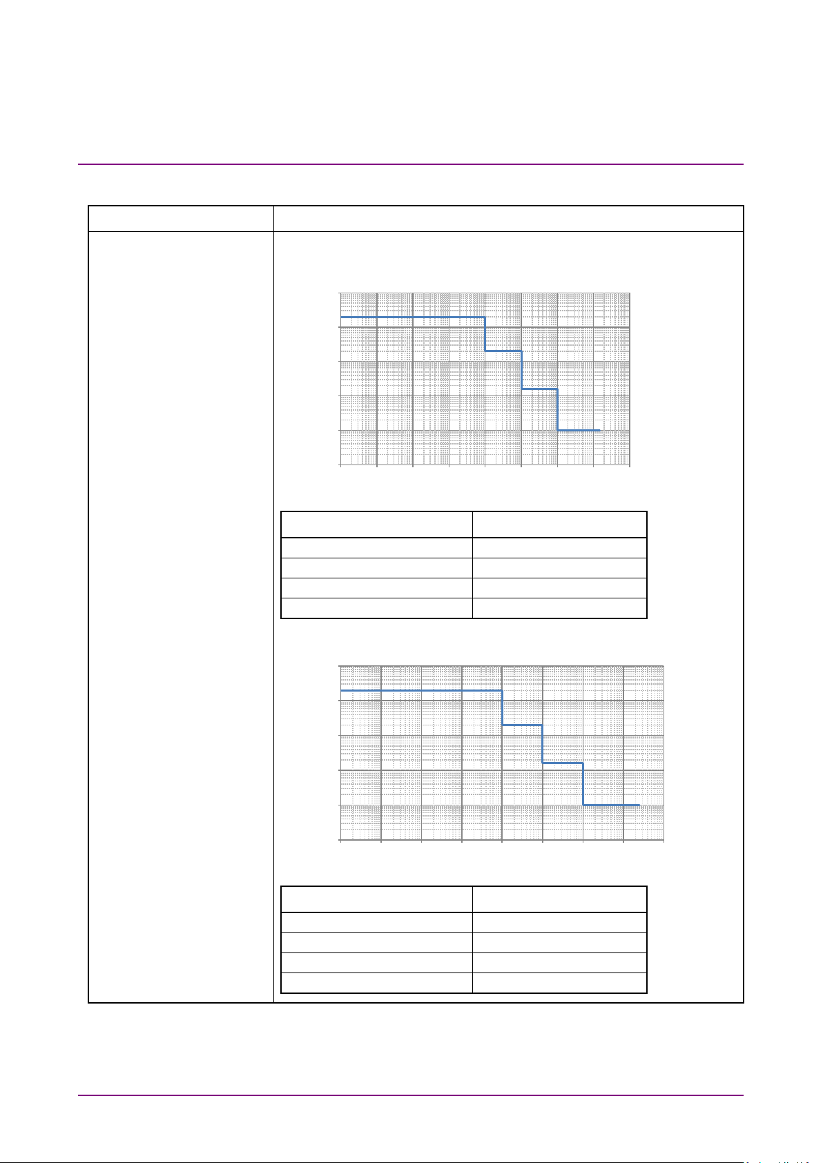
SJ1 Setting Range
When SJ2 switch is the built-in SJ2, the settable Jitter Amplitude is
halved.
SJ1 Clock Output Rate
30 < Baud rate ≤ 32.1 Gbaud, 15 < Baud rate ≤ 17 Gbaud
10 to 100k
0 to 2000
100.1k to 1M
0 to 200
1.001M to 10M
0 to 16
10.01M to 150M
0 to 1
17 < Baud rate ≤ 30 Gbaud
10 to 100k
0 to 2000
100.1k to 1M
0 to 200
1.001M to 10M
0 to 16
10.01M to 250M
0 to 1
10000
10000
Chapter 1 Overview
Item Specifications*
At Full Rate
Table 1.3.1-2 Jitter Setting Range
1000
100
1
10
Jitter Amplitude [UI p-p]
1
0.1
10 100 1k 10k 100k 1M 10M 100M 1000M
Modulation Frequency (Hz) Jitter Amplitude (UIp-p)
1000
100
10
Jitter Amplitude [UI p-p]
1
Modulation Frequency [Hz]
0.1
10 100 1k 10k 100k 1M 10M 100M 1000M
Modulation Frequency (Hz) Jitter Amplitude (UIp-p)
*1: When linking with MU181000A/B and MU181500B
1-12
Modulation Frequency [Hz]
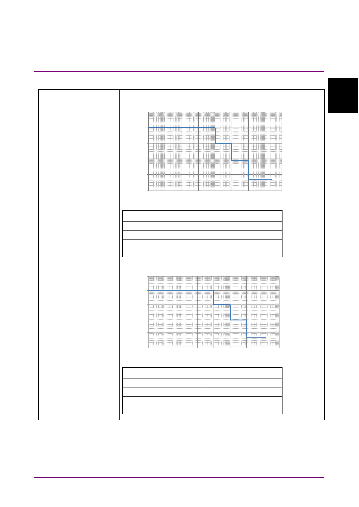
Overview
Item Specifications*
SJ1 Clock Output Rate
8.5 < Baud rate ≤ 15 Gbaud
10 to 100k
0 to 1000
100.1k to 1M
0 to 100
1.001M to 10M
0 to 8
10.01M to 250M
0 to 0.5
4 < Baud rate ≤ 8.5 Gbaud
10 to 100k
0 to 1000
100.1k to 1M
0 to 100
1.001M to 10M
0 to 8
10.01M to 150M
0 to 0.5
10000
10000
At Full Rate (Cont'd)
Table 1.3.1-2 Jitter Setting Range (Cont’d)
1000
100
1.3 Specifications
1
1
10
Jitter Amplitude [UI p-p]
1
0.1
10 100 1k 10k 100k 1M 10M 100M 1000M
Modulation Frequency [Hz ]
Modulation Frequency (Hz) Jitter Amplitude (UIp-p)
1000
100
10
Jitter Amplitude [UIp-p]
1
0.1
10 100 1k 10k 100k 1M 10M 100M 1000M
Modulation Frequency [Hz ]
Modulation Frequency (Hz) Jitter Amplitude (UIp-p)
1-13
SJ1 Clock Output Rate
2.4 ≤ Baud rate ≤ 4 Gbaud
10 to 100k
0 to 500
100.1k to 1M
0 to 50
1.001M to 10M
0 to 8
10.01M to 100M
0 to 0.5
10000
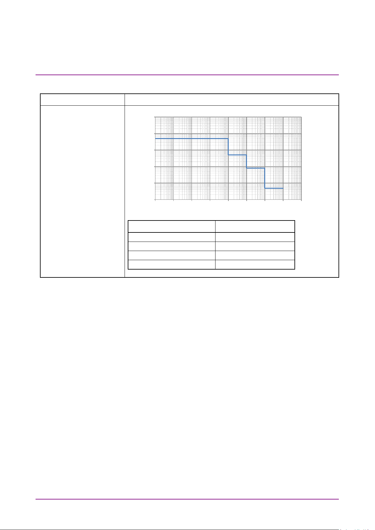
Chapter 1 Overview
Item Specifications*
At Full Rate (Cont'd)
Table 1.3.1-2 Jitter Setting Range (Cont’d)
1000
100
1
10
Jitter Amplitude [UIp-p]
1
0.1
10 100 1k 10k 100k 1M 10M 100M 1000M
Modulation Frequency [Hz ]
Modulation Frequency (Hz) Jitter Amplitude (UIp-p)
1-14
Overview
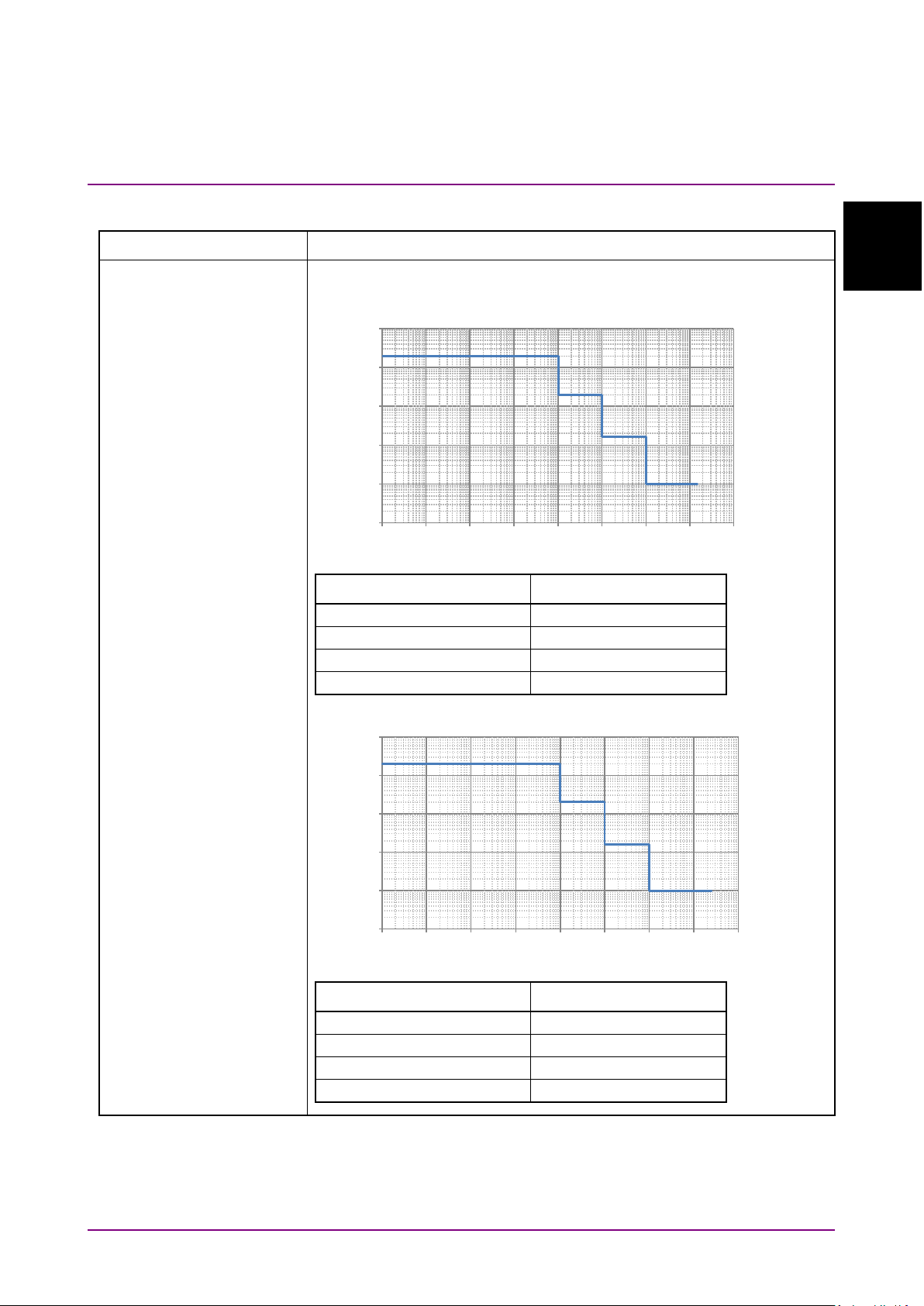
Table 1.3.1-2 Jitter Setting Range (Cont’d)
SJ1 Clock Output Rate
60 < Baud rate ≤ 64.2 Gbaud,
10 to 100k
0 to 2000
100.1k to 1M
0 to 200
1.001M to 10M
0 to 16
10.01M to 150M
0 to 1
34 < Baud rate ≤ 60 Gbaud, 17 < Baud rate ≤ 30 Gbaud
10 to 100k
0 to 2000
100.1k to 1M
0 to 200
1.001M to 10M
0 to 16
10.01M to 250M
0 to 1
10000
10000
Item Specifications*
1.3 Specifications
1
1
At Half Rate, Quarter
Rate
30 < Baud rate ≤ 34 Gbaud,
8 < Baud rate ≤ 17 Gbaud
1000
100
10
Jitter Amplitude [UIp-p]
1
0.1
10 100 1k 10k 100k 1M 10M 100M 1000M
Modulation Frequency [Hz ]
Modulation Frequency (Hz) Jitter Amplitude (UIp-p)
1000
100
10
Jitter Amplitude [UI p-p]
1
0.1
10 100 1k 10k 100k 1M 10M 100M 1000M
Modulation Frequency (Hz) Jitter Amplitude (UIp-p)
Modulation Frequency [Hz]
1-15
SJ1 Clock Output Rate
2.4 < Baud rate ≤ 8 Gbaud
10 to 100k
0 to 2000
100.1k to 1M
0 to 200
1.001M to 10M
0 to 16
10.01M to 100M
0 to 1
Baud rate 2.4 Gbaud
10 to 100k
0 to 2000
100.1k to 1M
0 to 200
1.001M to 10M
0 to 16
10.01M to 50M
0 to 1
10000
10000
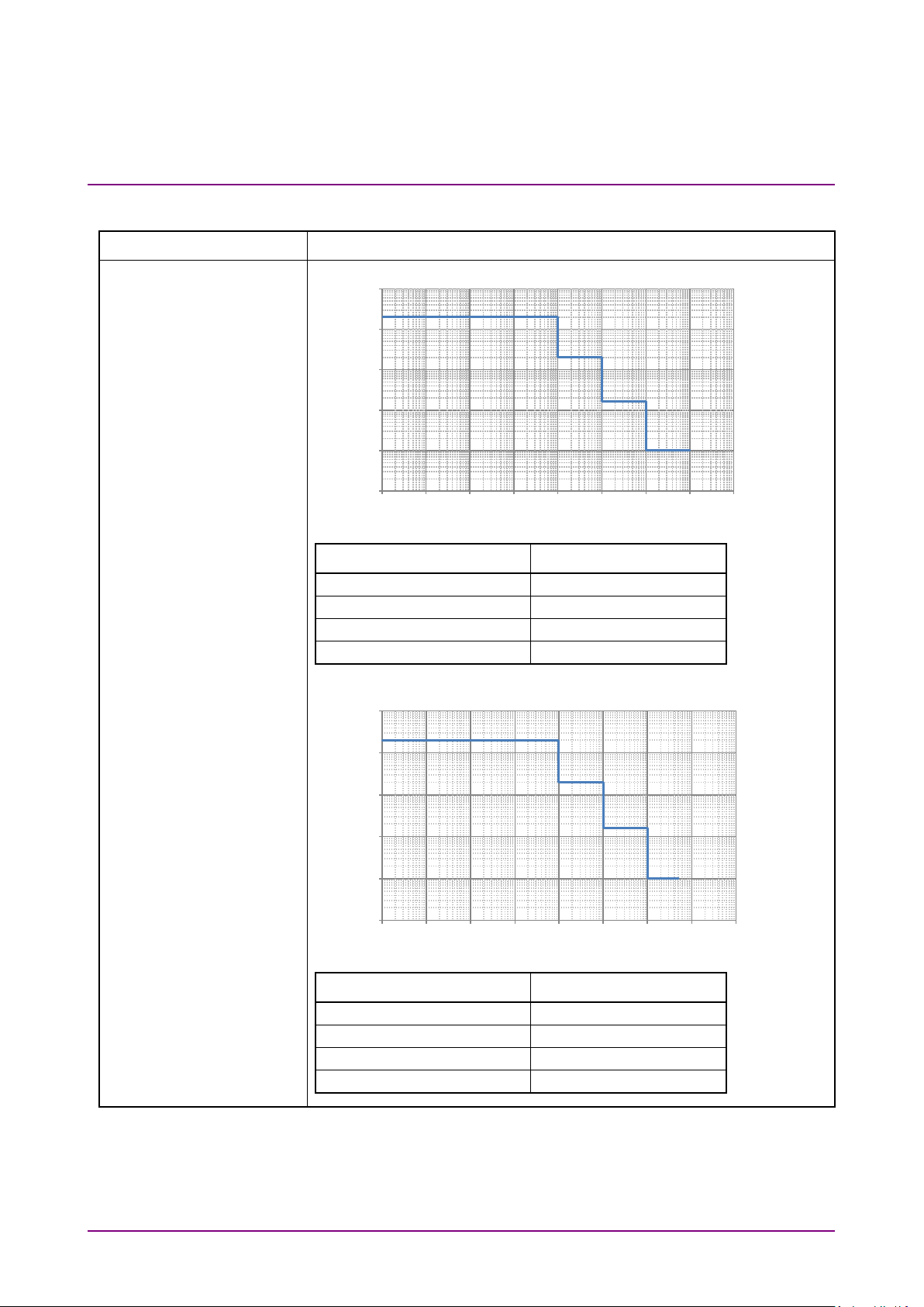
Chapter 1 Overview
Item Specifications*
At Half Rate, Quarter
Rate (Cont'd)
Table 1.3.1-2 Jitter Setting Range (Cont’d)
1000
100
1
10
Jitter Amplitude [UIp-p]
1
0.1
10 100 1k 10k 100k 1M 10M 100M 1000M
Modulation Frequency [Hz ]
Modulation Frequency (Hz) Jitter Amplitude (UIp-p)
1000
100
10
Jitter Amplitude [UIp-p]
1
0.1
10 100 1k 10k 100k 1M 10M 100M 1000M
Modulation Frequency [Hz ]
1-16
Modulation Frequency (Hz) Jitter Amplitude (UIp-p)
 Loading...