

MAINTENANCE MANUAL
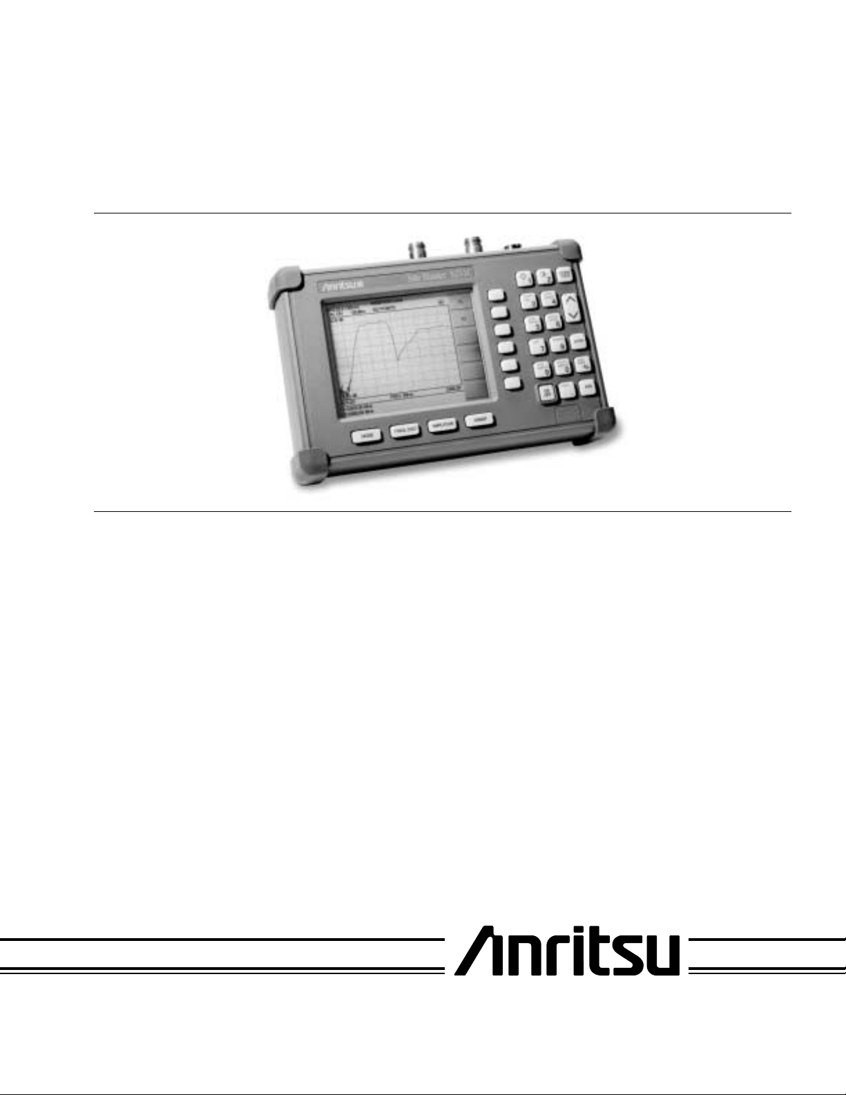
Site Master™ Model S251C
Antenna and Cable Analyzer
Figure 1. Site Master Model S251C
1. INTRODUCTION
This manual provides maintenance instructions for
the Site Master S251C Antenna and Cable Analyzer.
It describes the product and provides performance
verification procedures, parts replacement proce
-
dures, and a replaceable parts list.
2. DESCRIPTION
The Site Master (Figure 1) is a hand held S
mission gain or loss), SWR/RL (standing wave ra
21
(trans
tio/return loss), and Distance-To-Fault measurement
instrument. It combines a synthesized source, VSWR
Bridge, and receiver on a single printed circuit board
(PCB). An optional power monitor is also available. A
block diagram is shown in Figure 2.
3. PERFORMANCE VERIFICATION
Paragraphs 4 through 10 contain tests that can be
used to verify the performance of the Site Master
model S251C having any version of firmware.
3.1. Initial Setup for Testing
1. Press and hold the
press the
-
ter. (This sets the instrument to the factory
ON/OFF key to turn on the Site Mas
ESCAPE/CLEAR key, then
preset state.)
2. If necessary, use the Up/Down arrow key to
adjust the contrast to give a readable display.
Press
ENTER to accept.
-
490 JARVIS DRIVE ¨ MORGAN HILL, CA 95037-2809
P/N: 10580-00067
REVISION B
PRINTED: FEBRUARY 2003
COPYRIGHT 2001-2003 ANRITSU CO.
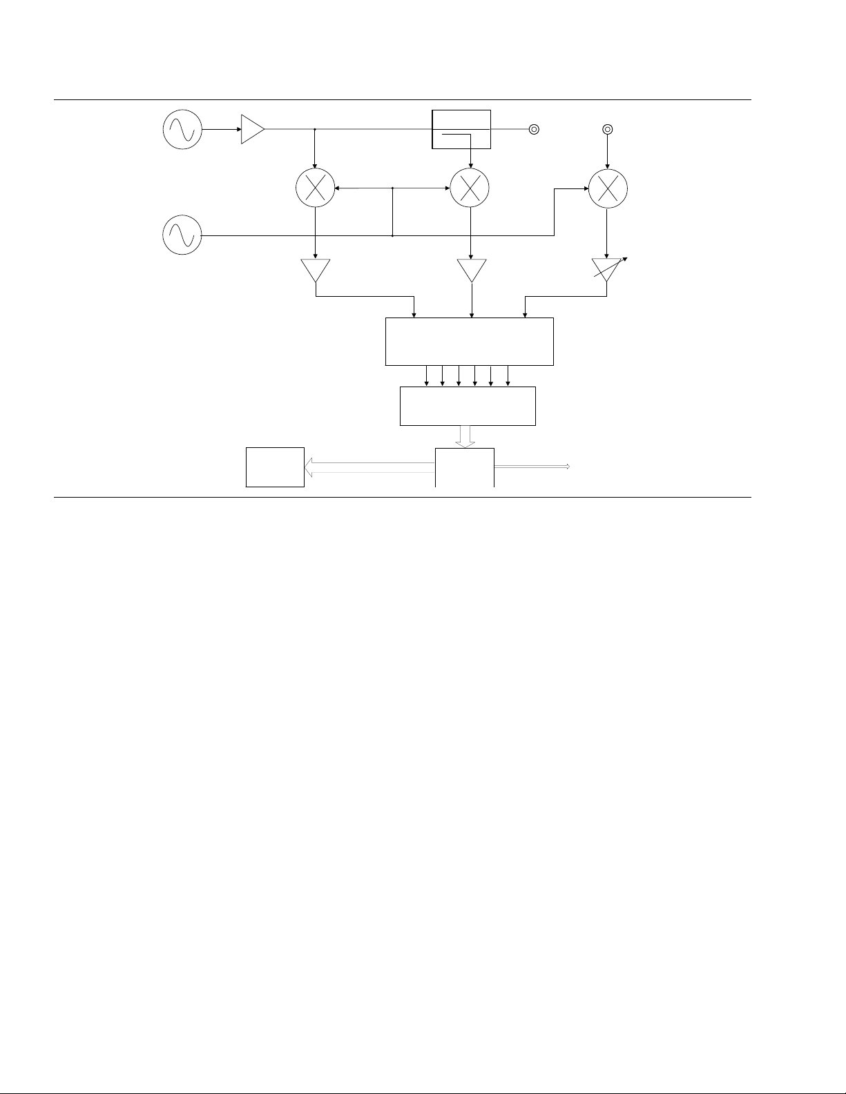
R F
S o u r c e
C o u p l e r
R F O u t
P o r t
R F I n
P o r t
I n c i d e n t
L o c a l
O s c i l l a t o r
D i s p l a y
Figure 2. Site Master Block Diagram
4. FREQUENCY ACCURACY
The following test can be used to verify the CW frequency accuracy of the Site Master. Measurement
calibration of the Site Master is not required for this
test.
a. Equipment Required:
·
Spectrum Analyzer
Anritsu Model MS2668C or equivalent
b. Procedure:
1. Press and hold the
press the
ON/OFF key to turn on the Site Mas
ESCAPE/CLEAR key, then
ter. (This sets the instrument to the factory
preset state.)
NOTE
Before continuing, allow a five minute
warm up for the internal circuitry to
stabilize.
2. Press the
3. Use the Up/Down Arrow key to highlight
SOURCE
4. Press the
MODE key.
RF
, then press ENTER.
FREQ soft key.
R e f l e c t e d
S y n c h r o n o u s
D e t e c t o r
A / D C o n v e r t e r
C P U
T r a n s m i t t e d
S e r i a l
P o r t
5. Using the keypad or Up/Down Arrow key enter 1000.0 MHz then press the
ENTER key.
6. Connect the RF cable from the Site Master
RF Out Test Port to the RF Input on the Spectrum Analyzer.
7. Set up the Spectrum Analyzer as follows:
(a) Press
Preset
(b) Press the PRESET ALL soft key
(c) Press
(d) Press
-
(e) Press
Frequency and enter 1 GHz
Span and enter 200 kHz
Amplitude
(f) Press the REFERENCE LEVEL soft key and
enter 10 dB
8. If the Site Master has gone into the hold
mode, press the
RUN/HOLD key to make the
measurement.
9. On the Spectrum Analyzer:
(a) Press
Marker
(b) Press PEAK SEARCH. The frequency
should be 1000 MHz ±75 kHz.
2 Site Master S251C MM
5. TRANSMISSION/ISOLATION
VERIFICATION
The following test can be used to verify transmission
test port isolation and the accuracy of transmission
measurements. Measurement calibration of the Site
Master is required for this test.
TransTest Port
TestPort
Extension Cable
Refl Test Port
a. Equipment Required:
10 dB Attenuator, Weinshel 1-10
·
30 dB Attenuator, Weinshel 1-30
·
Open/Short, Anritsu 22NF50
·
50 Ohm Terminations,
·
Anritsu SM/PL or 28N50-2
Anritsu SM/PLNF or 28NF50-2
Armored Test Port Extension Cable,
·
1.5 Meter, N(m) to N(m),
Anritsu 15NN50-1.5A
b. Procedure:
1. Press and hold the
press the
ON/OFF key to turn on the Site Mas-
ESCAPE/CLEAR key, then
ter. (This sets the instrument to the factory
preset state.)
NOTE
Before continuing, allow a five minute
warm up for the internal circuitry to
stabilize.
2. Press the
MODE key.
3. Use the Up/Down Arrow key to highlight
SERTION LOSS
4. Press the
5. Press the
, then press ENTER.
AMPLITUDE key.
TOP soft key.
6. On the keypad, press “0”, then press
(Verify the bottom limit is set to –120 dB.)
7. Press the
LIMIT key.
IN
ENTER.
Site Master S251C
MODE
FREQ/DIST
SWEEP
AMPLITUDE
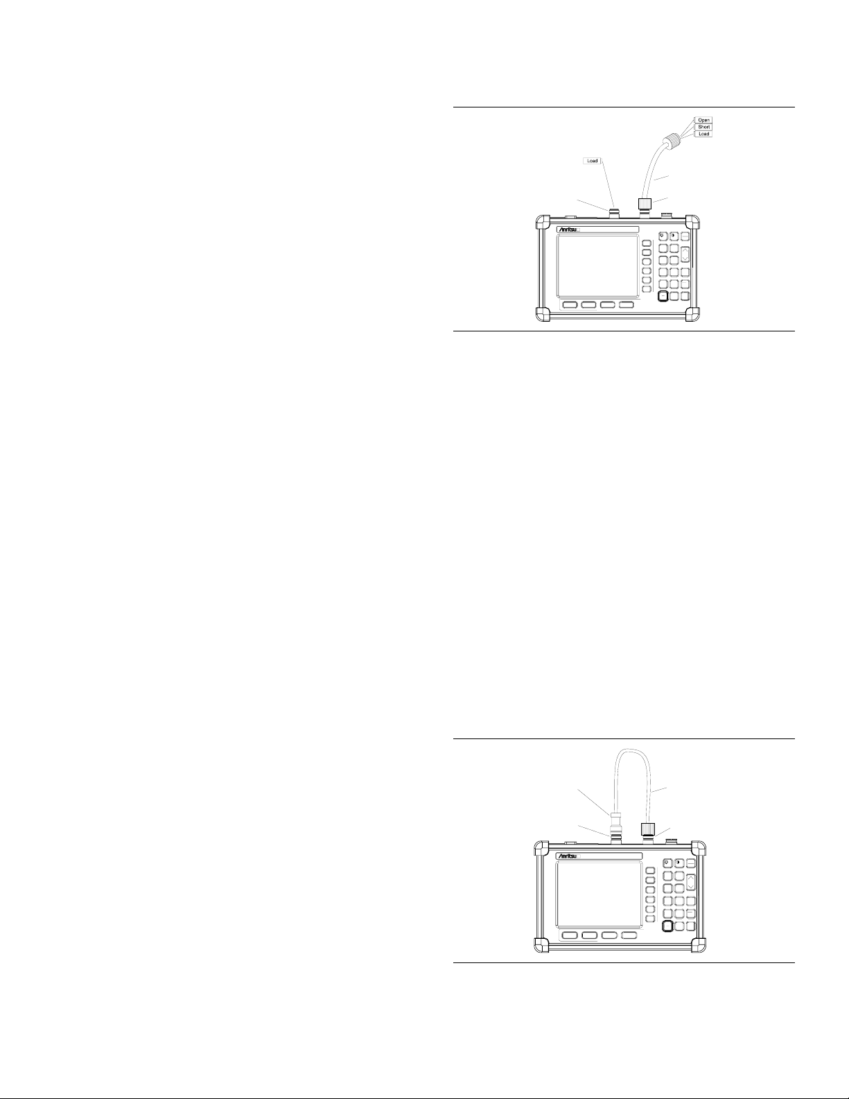
Figure 3. OSL-THRU-ISOL Calibration Setup
12. Connect a Load (28N50-2 or SM/PL) to the
RF In Test Port and verify that the noise floor
(isolation) is below –80 dB.
13. Press the
14. Press the
MARKER key.
M1 soft key, then the EDIT soft key.
15. Using the keypad or the Up/Down Arrow key,
enter 1000.0 MHz, and press
NOTE
For the following steps in the procedure,
use only attenuators that have Type N
connectors. The use of attenuators with
other type connectors and adapters will
cause measurement errors.
16. Connect the 10 dB attenuator to the RF In
-
Test Port (refer to Figure 4) and verify that
the reading is –10 dB ±2.25 dB @ 1000 MHz.
17. Connect the 10 dB and 30 dB attenuators in
series to the RF In Test Port and verify that
the reading is –40 dB ±3.25 dB @ 1000 MHz.
Attenuator
ESCAPE
CLEAR
2
1
START
AUTO
CAL
SCALE
3
4
SAVE
RECALL
SETUP
SETUP
6
5
LIMIT
MARKER
ENTER
8
7
RECALL
RUN
SAVE
DISPLAY
DISPLAY
HOLD
+
9
0
-
/
PRINT
ON
SYS
OFF
.
ENTER.
TestPort
Extension Cable
8. Press the
9. Press the
the
10. Press the
11. Follow the instructions on the display to per
form a OSL-THRU-ISOL calibration using a
22NF50 Open/Short, 28NF50-2 or SM/PLNF
Terminations, and 15NN50-1.5ATest Port Ex
tension Cable (refer to Figure 3).
SINGLE LIMIT soft key.
EDIT soft key, enter –80, and press
ENTER key.
START CAL key.
-
-
Figure 4. Test Setup
TransTest Port
Refl Test Port
Site Master S251C
MODE
FREQ/DIST
AMPLITUDE
SWEEP
ESCAPE
CLEAR
2
1
START
AUTO
CAL
SCALE
3
4
SAVE
RECALL
SETUP
SETUP
6
5
LIMIT
MARKER
ENTER
8
7
RECALL
RUN
SAVE
DISPLAY
DISPLAY
HOLD
+
9
0
-
/
PRINT
ON
SYS
OFF
.
Site Master S251C MM 3
6. RETURN LOSS VERIFICATION
The following test can be used to verify the accuracy
of return loss measurements. Measurement calibra
tion of the Site Master is required for this test.
a. Equipment Required:
5. Follow the instructions on the screen to per
-
form a calibration using a 22N50 Open/Short
-
and 28N50-2 or SM/PL Termination.
6. Connect the 20 dB offset to the RF Out Test
Port and verify that the reading is 20 dB
±1.7 dB
20 dB offset, Anritsu SC5270
·
6 dB offset, Anritsu SC5237
·
Open/Short, Anritsu 22N50
·
50 Ohm Termination,
·
Anritsu 28N50-2 or SM/PL
b. Procedure:
1. Press and hold the
press the
ON/OFF key to turn on the Site Mas
ESCAPE/CLEAR key, then
ter. (This sets the instrument to the factory
preset state.)
NOTE
Before continuing, allow a five minute
warm up for the internal circuitry to
stabilize
2. Press the
MODE key.
3. Use the Up/Down Arrow key to highlight
TURN LOSS
4. Press the
, then press ENTER.
START CAL key.
RE-
7. Connect the 6 dB offset to the RF Out Test
Port and verify that the reading is 6 dB
±1.2 dB
7. POWER MONITOR VERIFICATION
If the Power Monitor (Option 5) is installed in the
Site Master, the following test can be used to verify
the accuracy of the power measurements. Measure
ment calibration of the Site Master is not required
for this test.
-
a. Equipment Required:
RF Detector, 10 MHz to 20 GHz,
·
Anritsu 560-7N50B
· 10 dB Attenuator, Weinschel 1-10
· 30 dB Attenuator, Weinschel 1-30
· RF Reference Source, 0.050 GHz,
Anritsu MA2418A
· DC Power Supply, Anritsu 2000-933
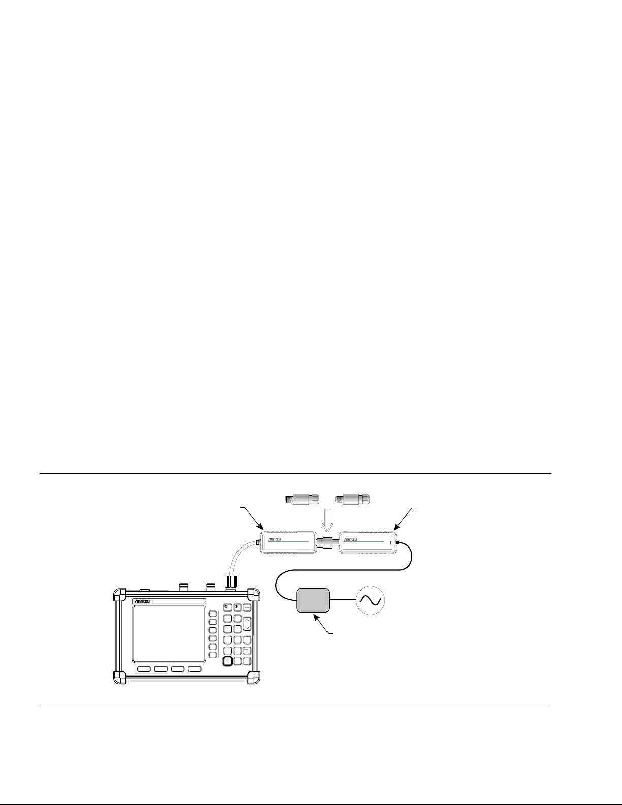
-
Attenuators
560-7N50B
RF Detector
MA2418AReference Source
W
50MHz, 50
0dBm
Site Master S251C
MODE
FREQ/DIST
AMPLITUDE
SWEEP
ESCAPE
CLEAR
2
1
START
AUTO
CAL
SCALE
3
4
SAVE
RECALL
SETUP
SETUP
6
5
LIMIT
MARKER
ENTER
8
7
RECALL
RUN
SAVE
DISPLAY
DISPLAY
HOLD
+
9
0
-
/
PRINT
ON
SYS
OFF
.
DC Power Supply 2000-933
20mA
15-24VDC
MA2418A
Reference Source
Site Master w/ Option 5 Installed
Figure 5. Power Monitor Verification
4 Site Master S251C MM

b. Procedure
1. Connect the DC power supply to the
MA2418A Reference Source. (Refer to Figure
5.)
2. Connect the MA2418A Reference Source to
the input of the 560-7N50B RF detector.
3. Connect the RF Detector output to the RF De
tector input of the Site Master.
(Option 10A only works with the AC-DC
Adapter).
2. Apply AC power to the power supply.
3. Press and hold the
press the
ON/OFF key to turn on the Site Mas
ESCAPE/CLEAR key, then
-
ter. (This sets the instrument to the factory
-
preset state.)
4. Press the
SYS key.
4. Connect the DC power supply to the appropri
ate line voltage to supply power to the
MA2418A Reference Source.
5. Press and hold the
press the
ON/OFF key to turn on the Site Mas
ESCAPE/CLEAR key, then
ter. (This sets the instrument to the factory
preset state.)
6. Press the
MODE key.
7. Use the Up/Down Arrow key to highlight
POWER MONITOR, then press ENTER.
8. Press the
ZERO soft key to zero the power
monitor.
When complete,
ZERO ADJ:ON is displayed in
the message area.
9. Verify that the power monitor reading is
0.0 dBm ±1 dB.
10. Connect the output of the MA2418A Reference Source to the two attenuators so as to
add 40 dB of attenuation (Figure 5).
11. Connect the MA2418A Reference Source and
the attenuators to the input of the 560-7N50B
RF detector.
-
5. Press the
6. Press the
OPTIONS soft key.
BIAS-T soft key to activate the Bias
Tee option.
-
7. Verify that the display shows
15.0V, 0 mA.
8. Connect the 22NF50 short to the RF In test
port.
9. Verify the test port voltage relay clicks on and
off, and
FAULT is shown in the upper left cor
ner of the display.
10. Remove the short and install the 100 Ohm
load.
CAUTION
The 100 Ohm resistor will get hot. Verify the readings and remove the 100
Ohm load immediately.
11. Verify that the display shows
BIAS, with a
reading of 14.8 to 15.3 Volts, and 120 to 160
milliamps.
9. BIAS T (OPTION 10B) VERIFICATION
a. Equipment Required:
-
·
12. Verify that the power monitor reading is now
–40.0 dBm ±2 dB.
8. BIAS T (OPTION 10A) VERIFICATION
a. Equipment Required:
·
AC-DC Adapter Power Supply 40-115
·
Open/Short, Anritsu 22N50
·
100 Ohm, 1 Watt load (100 Ohm, 1 Watt re
sistor soldered from the center pin to ground
of an N-type connector.)
b. Procedure:
1. Connect the AC-DC Adapter Power Supply to
the battery charging port on the Site Master
-
Open/Short, Anritsu 22N50
·
100 Ohm, 1 Watt load (100 Ohm, 1 watt resis
tor soldered from the center pin to ground of
a N-type connector)
·
Anritsu T2904
b. Procedure:
1. Ensure the battery is fully charged. (Option
10B only works with the battery).
2. Press and hold the
press the
ON/OFF key to turn on the Site Mas
ESCAPE/CLEAR key, then
ter. (This sets the instrument to the factory
preset state.)
3. Press the
4. Press the
SYS key.
OPTIONS soft key.
Site Master S251C MM 5
-
-

5. Press the BIAS-T soft key to activate the Bias
Tee option.
NOTE
When the Bias Tee option is selected,
the unit is automatically forced into sin
-
gle sweep mode.
6. Press the
ON/OFF soft key.
7. Verify that 15.1V, 0 mA is shown in the upper
left corner of the display.
10. TERMINATION VERIFICATION
This test verifies the accuracy of the Site Master
SM/PL termination using the precision return loss
mode of the 541XXA Scalar Measurement System.
Measurements of terminations using this mode pro
vide results that are traceable to the NIST (National
Institute of Standards and Technology) standards for
the precision airline.
a. Equipment Required:
8. Connect the 22N50 SHORT to the RF In test
port.
9. Press the
RUN/HOLD key.
NOTE
The message “
displayed whenever the
Powering up TMA…” will be
RUN/HOLD key
is pressed.
10. Verify the test port voltage relay clicks on and
off, and
FAULT is shown in the upper left cor
-
ner of the display.
11. Remove the 22N50.
12. Select LOW VOLTAGE (12V) and LOW CURRENT (460 mA(), 244 mA(–)) by pressing
LOW/HIGH VOLTAGE soft key.
the
13. Connect the 100 Ohm load to the
RF In test
port.
14. Press the
RUN/HOLD key and verify the read-
ing displayed in upper left corner is
approximately 11.9V to 12.9V, 120 mA to 160
mA.
15. Remove the 100 Ohm load.
16. Select HIGH VOLTAGE (15V) and HIGH
CURRENT (1A(), 650 mA(–)) by pressing the
LOW/HIGH VOLTAGE and LOW/HIGH CURRENT
soft keys.
17. Connect the T2904 to the
18. Press the
RUN/HOLD key and verify the read
ing displayed in upper left corner is approxi
RF In test port.
-
-
mately 14.8V to 15.3V, 343 mA to 379 mA.
Scalar Measurement System,
·
Anritsu 541XXA
Offset SWR Autotester,
·
Anritsu 560-97A50-20
Precision Airline, Anritsu 18N50
·
Open/Short, Anritsu 22N50
·
50 Ohm Termination, Anritsu 26N50
·
Source Adapter, Anritsu 34NN50A
·
b. Procedure
1. Connect the test equipment as shown in Figure 6.
2. Press the
3. Press the
Power key on the 541XXA to On.
System Menu key.
4. Using the Menu up-down keys: Highlight
SET
, then press the Select key.
5. At the
up-down keys to highlight
DEFAULTS
RESET MENU display, use the Menu
RESET TO FACTORY
, then press the Select key.
6. Set the signal source for the frequency range
as follows:
(a) Press the
Frequency key.
(b) Using the Data Entry Keypad or Data
Entry Knob, set the Start frequency to
0.01 GHz. Press the
Enter key.
(c) Using the Data Entry Keypad or Data
Entry Knob, set the Stop frequency to
4.0 GHz. Press the
Enter key.
RE-
7. Press the Channel 2 Display On/Off key to
Off.
8. Press the Channel 1 Menu key.
9. Using the Menu up-down keys: Highlight
PRECISION RL, then press the Select key.
6 Site Master S251C MM

10. At the PRECISION RETURN LOSS menu
display, use the Menu up-down keys to high
light
FINAL, then press the Select key.
11. Press the
12. At the CALIBRATION menu display, use the
Menu up-down keys to highlight
then press the
13. At the PRECISION RETURN LOSS CALI
BRATION menu display prompt, connect the
Offset SWR Autotester to Input A, if you have
not done so yet.
14. Connect the precision air line to the Offset
SWR Autotester test port. Position the air
line pointing vertically upward. Downward or
horizontal positions make connector pin
alignment difficult.
Calibration key.
START CAL,
Select key.
-
16. At the PRECISION RETURN LOSS CALI
-
BRATION menu prompt, connect the Open to
the beadless end of the airline. Press the
lect
key to start the calibration.
17. Verify that the display resembles that shown
in Figure 8.
CAUTION
During both calibration and measure
ment, be sure to properly align the
beadless connector of the airline. When
the connectors are mis-aligned, a spike
will usually be visible on the display.
18. At the next menu prompt, remove the Open
and connect the Short to the beadless end of
the airline. Press the
calibration process.
Select key to start the
-
Se
-
-
NOTE
Ensure that the beadless end of the pre
cision airline is at the measurement con
nection point.
15. Press the
Select key when ready.
50 Ohm
Termination
541XXA Scalar Measurement System
-
-
Open/Short
Precision
Air Line
19. At the next menu prompt, remove the Short
and connect the 50 Ohm Termination to the
beadless end of the air line. Press the
key to start the calibration process.
20. When the calibration is complete, remove the
50 Ohm Termination.
Select
Termination
under Test
Beadless
End
Connect Dashed Line Connections
When Directed By Procedure
B
A
Source
Adapter
Figure 6. 541XXA Precision Return Loss Setup
Offset SWR
Autotester
Site Master S251C MM 7

2: OFF
10.0 dB/DIV OFFSET1: PRECSN RL (A)
2: OFF
+0.0dB
2 GHz/DIV
START: 0.0100 GHz
401 pts
STOP: 20.0000 GHz
LEVEL +7.0 dBm
54147A
CURSOR
1: -46.02 dB
PRESS SELECT
FOR
CURSOR MENU
10.0050 GHz
1
10.0 dB/DIV OFFSET1: PRECSN RL (A)
+0.0dB
54147A
PRECISION
RETURN LOSS
CALIBRATION
bles that shown in Figure 7.
22. Observe that the waveform displayed resem
-
1
START: 0.0100 GHz
401 pts
2 GHz/DIV
Figure 7. Example of a Good Connection
21. Connect the SM/PL termination to the
beadless end of the air line and press the Select key to begin the measurement.
STOP: 20.0000 GHz
LEVEL +7.0 dBm
CONNECT OPEN
TO AIRLINE
PRESS SELECT
WHEN READY
Figure 8. Direct Readout of the Precision Return Loss
23. Press the
Cursor On/Off key to On.
24. Observe the Cursor menu readout. The minimum return loss reading for the SM/PL termination should be 42 dB.
8 Site Master S251C MM

11. BATTERY PACK REMOVAL AND
REPLACEMENT
This procedure provides instructions for removing
and replacing the Site Master battery pack.
1. With the Site Master standing upright on a
stable surface, locate the battery access door
(Figure 9).
BATTERYACCESS DOOR
Figure 9. Battery Access Door Location
Figure 11. Removing the Battery Access Door
2. Lift up the access door handle and rotate it
90 degrees counterclockwise, as illustrated in
Figure 10.
Figure 10. Rotate the Battery Access Door Handle
3. Lift the door and remove, as illustrated in
Figure 11.
4. Grasp the battery lanyard and pull the bat
tery straight up and out of the unit, as illus
trated in Figure 12.
Figure 12. Removing the Battery
5. Replacement is the opposite of removal. Note
the orientation of the battery contacts, and
be sure to insert the new battery with the
contacts facing the rear of the unit (Figure
13).
BATTERYCONTACTS
-
-
Figure 13. Battery Orientation
Site Master S251C MM 9

12. BATTERY INFORMATION
The following information relates to the care and
handling of the Site Master battery, and NiMH bat
teries in general.
Figure 14. Site Master Battery
The Nickel Metal Hydride (NiMH) battery sup
·
plied with the Site Master is shipped in a dis
charged state. Before using the Site Master, the
internal battery must first be charged for three
hours, either in the Site Master or in the optional battery charger (Anritsu part number:
2000-1029).
The battery may need to be replaced when the
·
operating time between charging becomes no
-
-
-
ticeably shorter than normal.
Never use a damaged or worn out charger or
·
battery.
Storing the battery in extreme hot or cold
·
places will reduce the capacity and lifetime of
the battery.
Never short-circuit the battery terminals.
·
Do not drop, mutilate or attempt to disassemble
·
the battery.
Do not dispose of batteries in a fire!
·
Batteries must be recycled or disposed of prop
·
erly. Do not place batteries in household gar
bage.
Always use the battery for its intended purpose
·
only.
-
-
-
· Use only Anritsu approved battery packs.
· Recharge the battery only in the Site Master or
in an Anritsu approved charger.
· With a new NiMH battery, full performance is
achieved after three to five complete charge and
discharge cycles.
·
When the Site Master or the charger is not in
use, disconnect it from the power source.
·
Do not charge batteries for longer than 24
hours; overcharging may shorten battery life.
·
If left unused a fully charged battery will dis
charge itself over time.
·
Temperature extremes will affect the ability of
the battery to charge: allow the battery to cool
down or warm up as necessary before use or
charging.
·
Discharge an NiMH battery from time to time
to improve battery performance and battery
life.
·
The battery can be charged and discharged
hundreds of times, but it will eventually wear
out.
-
10 Site Master S251C MM

13. FRONT PANEL ASSEMBLY REMOVAL AND
REPLACEMENT
This procedure provides instructions for removing
and replacing the Site Master front panel assembly.
With the front panel assembly removed, the LCD
display, keypad PCB, keypad membrane, and main
PCB assemblies can be removed and replaced.
1. Place the Site Master face up on a work sur
-
face.
2. Remove the four rubber corner bumpers by
carefully sliding the bumpers off of the case
corners (Figure 15).
7. Carefully disconnect the LCD display
backlight cable from J15 on the main PCB.
J15
J1
J12
Figure 16. Site Master Front Panel Cable Connections
8. Remove the front panel assembly.
9. Reverse the above steps to replace the front
panel assembly.
Figure 15. Removing the Corner Bumpers
3. With the bumpers removed, the access holes
for the case screws are revealed. Use a Phillips screwdriver to remove the four screws
securing the two halves of the Site Master
case together.
4. Carefully lift up on the right side (as viewed
from the front) of the front half of the case
and begin to separate the two halves.
CAUTION
Do not force or pull the two halves of the
case apart as there are delicate cables
attached between the two halves that
must be disconnected first.
5. Carefully depress the latch tab and discon
nect the LCD display cable from J12 on the
main PCB.
The corner bumpers only mount one
way. That is, the raised area inside one
end of the bumper (Figure 17) is made
to conform to the contour of the front
cover only.
-
Figure 17. Corner Bumper Detail
NOTE
RAISED AREA
6. Carefully disconnect the keypad interface ca
-
ble from J1 on the main PCB.
Site Master S251C MM 11
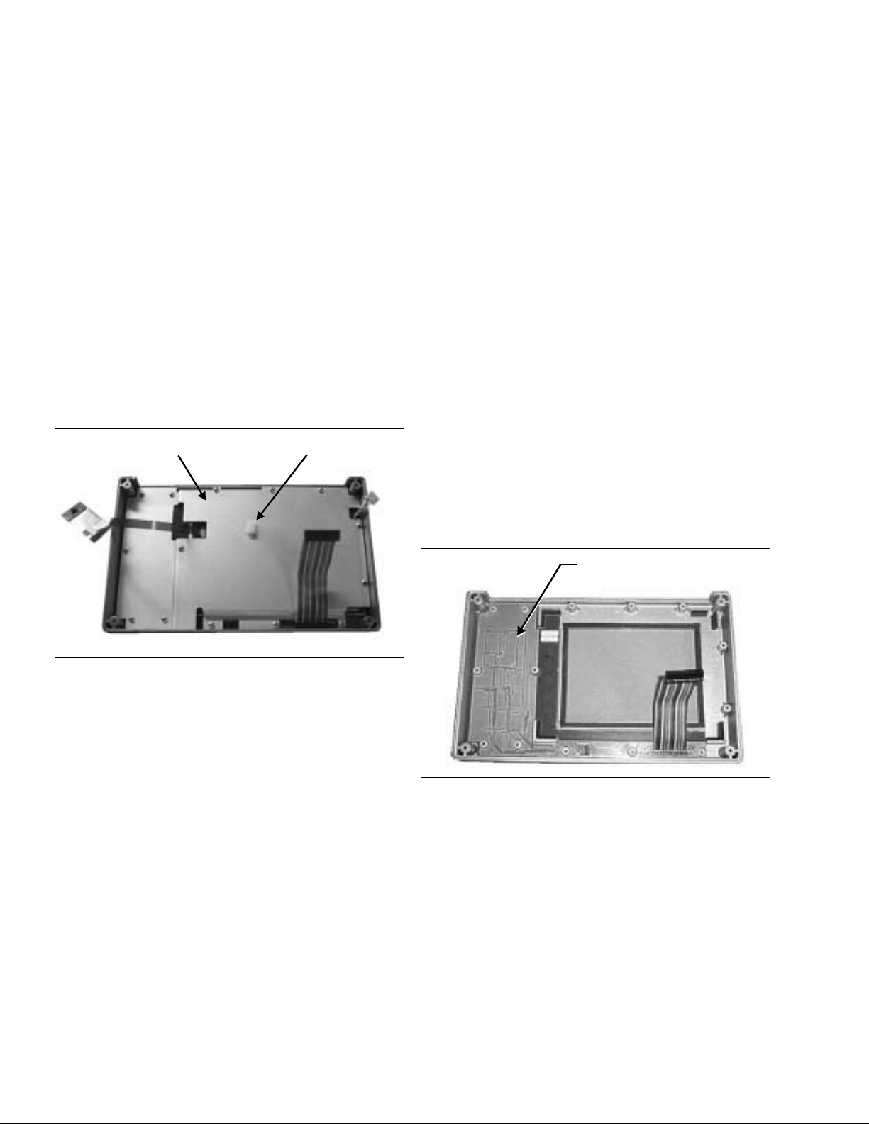
14. LCD ASSEMBLY REPLACEMENT
15. KEY PAD PCB REPLACEMENT
This procedure provides instructions for removing
and replacing the Liquid Crystal Display (LCD) once
the front panel assembly has been separated from
the Site Master.
1. Remove the front panel assembly as directed
in section 13.
2. Place the front panel assembly face down on
a protected work surface.
3. Remove the 14 Phillips screws that attach
the LCD retainer plate to the front panel as
sembly.
4. Release the LCD display cable from the cable
clamp on the LCD retainer plate.
LCD RETAINER PLATE LCD CABLE CLAMP
This procedure provides instructions for removing
and replacing the key pad PCB.
1. Remove the front panel assembly as directed
in section 13.
2. Place the front panel assembly face down on
a protected work surface.
3. Remove the 14 Phillips screws that attach
the backing plate to the front panel assem
bly.
-
4. Release the LCD display cable from the re
taining clip on the front panel backing plate
(Figure 19).
5. Remove the front panel backing plate, care
fully feeding the LCD cable through the ac
cess hole to avoid damage to the cable or con
nector.
6. Remove the rubber cushion pad from the key
pad PCB and remove the PCB.
-
-
-
-
-
Figure 18. Front Panel Backing Plate
5. Remove the LCD retainer plate, carefully
feeding the LCD cable through the access
hole to avoid damage to the cable or
connector.
6. Remove the rubber cushion pad from the
LCD assembly and remove the assembly.
7. Reverse the above steps to install the re
placement assembly.
KEYPAD PCB
Figure 19. Front Panel Keypad PCB Location
7. Reverse the above steps to install the re
-
placement assembly.
-
12 Site Master S251C MM

16. KEY PAD MEMBRANE REPLACEMENT
C
17. MAIN PCB ASSEMBLY REPLACEMENT
This procedure provides instructions for replacing
the key pad membrane.
1. Remove the front panel assembly as directed
in section 13.
2. Remove the key pad PCB as directed in sec
tion 15.
3. Remove the keypad membrane by gently
pulling the membrane up and out of the
holes in the front panel.
KEYPAD MEMBRANE
This procedure provides instructions for replacing
the main PCB assembly with the connector panel at
tached.
1. Remove the front panel assembly as directed
in section 13.
-
2. Disconnect the battery connector from J13
on the main PCB.
3. Remove the three PCB mounting screws and
remove the PCB assembly with the connector
panel attached.
BATTERY
ONNECTOR
-
Figure 20. Front Panel Keypad Membrane
4. Reverse the above steps to install the replacement membrane.
PCB MOUNTING
SCREWS (3)
Figure 21. Main PCB
OPTION 10A
4. If Option 10A is installed (Figure 21) remove
the option PCB by gently squeezing the
standoff mounts to release the option PCB
and disconnect it from the main board. Re
move the standoffs and install them on the
new main PCB, then install the Option 10A
PCB on the new main PCB.
5. Reverse the above steps to install the new
main PCB.
NOTE
The main PCB connector panel fits into
grooves in the two halves of the Site
Master case. Make sure the panel is cor
rectly aligned with the grooves before
reassembling the two halves together.
-
-
Site Master S251C MM 13

18. REPLACEABLE PARTS
Replaceable parts for the Site Master Model S251C
are listed below.
Table 1. Replaceable Parts List
Part Number Description Qty
Accessories
10580-00065
10580-00066
2300-347 Software Tools, Site Master 1
40-115 Power Supply 1
2000-1029 Battery Charger
22N50 Precision Short/Open, N Male 1
SM/PL Connector, RF Termination 1
806-62 Cable Assy, Cig Plug, Female 1
800-441 Serial Interface Cable Assembly 1
48258 Soft Carrying Case 1
510-87 N-Connector 2
ND57371 Opt. 05 Input Connector w/cable 1
15-102 Liquid Crystal Display Assy 1
633-27 Rechargeable Battery, NiMH 1
ND57372 Main PCB Assembly,S251C 1
ND57373
ND57374
ND57375
ND60688
ND60690
52737-3 Keypad PCB Assembly 1
46649-1 Membrane Keypad, Main 1
User's Guide, Site Master
S251C
Programming Manual, Site Mas
ter S251C
(available on disk only)
Replaceable Parts
Main PCB Assembly,S251C with
Option 05
Main PCB Assembly,S251C with
Option 10A
Main PCB Assembly,S251C with
Option 05 and Option 10A
Main PCB Assembly,S251C with
Option 10B
Main PCB Assembly,S251C with
Option 05 and Option 10B
-
Part Number Description Qty
Hardware
1
1
1
1
900-160 Pan Head Screw, 4-40, 0.875 4
900-861 Pan Head Screw, 4-20, 0.365 15
900-869 Screw, 4-40, 0.875 4
900-720 Screw, 4-40, 0.187 3
900-754 Pan Head Screw, 4-40, 0.750 4
900-697 Screw, 4-40, 0.312 3
785-929 M-F Stand off, 4-40, 11/16 3
900-326 Kep Nut, 4-40, 0.187 8
790-516 Hole Plug, 0.6875L 1
790-42 Hole Plug, 0.625 1
761-79 Cap Vinyl, Black, round 1
Case Parts
46652-1 Top Case only 1
46653-1 Bottom Case only 1
48231-1 Battery Door 1
790-509
790-510
790-511
46655 Case Corner Bumpers 4
46662 LCD Retainer Plate 1
48241 Foam, LCD Corners 8
48278 Foam, LCD Window 1
46659 Foam, LCD Backing 1
46661 Foam, Keypad Backing 1
48246 Foam, Battery Door 1
48271 Foam, Battery Compartment 1
720-19 Cable Clamp 1
790-515 Spring, Battery Compartment 1
55217 ID Label, Model S251C 1
Battery Door Latch (3 pieces)
1
14 Site Master S251C MM

Table 2. Anritsu Service Centers
UNITED STATES
ANRITSU COMPANY
490 Jarvis Drive
Morgan Hill, CA 95037-2809
Telephone: (408) 776-8300
FAX: 408-776-1744
ANRITSU COMPANY
10 NewMaple Ave., Suite 305
Pine Brook, NJ 07058
Telephone: 973-227-8999
FAX: 973-575-0092
ANRITSU COMPANY
1155E. Collins Blvd
Richardson, TX 75081
Telephone: 1-800-ANRITSU
FAX: 972-671-1877
AUSTRALIA
ANRITSU PTY. LTD.
Unit 3, 170 Foster Road
Mt Waverley, VIC 3149
Australia
Telephone: 03-9558-8177
FAX: 03-9558-8255
BRAZIL
ANRITSU ELECTRONICA LTDA.
Praia de Botafogo 440. Sala 2401
CEP22250-040,Rio de Janeiro,RJ, Brasil
Telephone: 021-527-6922
FAX: 021-53-71-456
CANADA
ANRITSU INSTRUMENTS LTD.
700 Silver Seven Road, Suite 120
Kanata, Ontario K2V 1C3
Telephone: (613) 591-2003
FAX: (613) 591-1006
CHINA (SHANGHAI)
ANRITSU ELECTRONICS CO LTD
2F,Rm.B, 52 Section Factory Bldg.
NO 516 Fu Te Road (N)
Waigaoqiao Free Trade Zone
Pudong, Shanghai 200131
PR CHINA
Telephone: 86-21-58680226
FAX: 86-21-58680588
FRANCE
ANRITSU S.A
9 Avenue du Quebec
Zone de Courtaboeuf
91951 Les Ulis Cedex
Telephone: 016-09-21-550
FAX: 016-44-61-065
GERMANY
ANRITSU GmbH
Grafenberger Allee 54-56
D-40237 Dusseldorf
Germany
Telephone: 0211-968550
FAX: 0211-9685555
INDIA
MEERA AGENCIES (P) LTD
23 Community Centre
Zamroodpur, Kailash Colony Extension
New Delhi, India 110 048
Telephone: 011-644-2700
FAX: 011-644-2500
ISRAEL
TECH-CENT, LTD
4 Raul ValenbergSt.
Tel-Aviv, Israel 69719
Telephone: 972-36-478563
FAX: 972-36-478334
ITALY
ANRITSU Sp.A
Rome Office
Via E. Vittorini, 129
00144 Roma EUR
Telephone: (06) 50-2299-711
FAX: 06-50-22-4252
JAPAN
ANRITSU CUSTOMER SERVICES LTD.
1800 Onna Atsugi—shi
Kanagawa-Prf. 243 Japan
Telephone: 0462-96-6688
FAX: 0462-25-8379
KOREA
ANRITSU SERVICE CENTER
8F Hyunjuk-Bldg, 832-41
Yeoksam-Dong
Kangnam-Gu
Seoul, 135-080, Korea
Telephone: 82-2-553-6603
FAX: 82-2-553-6605
SINGAPORE
ANRITSU (SINGAPORE) PTE LTD
10, Hoe Chiang Road
#07-01/02
Keppel Towers
Singapore 089315
Telephone:65-282-2400
FAX:65-282-2533
SOUTH AFRICA
ETESCSA
12 Surrey Square Office Park
330 Surrey Avenue
Ferndale, Randburt, 2194
South Africa
Telephone: 011-27-11-787-7200
Fax: 011-27-11-787-0446
SWEDEN
ANRITSU AB
Botvid Center
Fittja Backe 13A
145 84
Stockholm, Sweden
Telephone: (08) 534-707-00
FAX: (08)534-707-30
TAIWAN
ANRITSU COMPANY
7F, NO.316, Sec.1,
Nei Hu Road
Taipei, Taiwan, R.O.C.
Telephone: 886-2-8751-2126
FAX: 886-2-8751-1817
UNITED KINGDOM
ANRITSU LTD.
200 Capability Green
Luton, Bedfordshire
LU1 3LU, England
Telephone: 015-82-43-3200
FAX: 015-82-73-1303

 Loading...