

Site Master is the preferred cable and antenna analyzer of
wireless providers, contractors and installers.
Site Master
™
S331D/S332D
Cable and Antenna Analyzer
User’s Guide
MS2712
MS2712
MS2712
SiteMaster
SpectrumMaster
CellMaster
MS2711D
Spectrum Master
S331D
Site Master
SiteMaster
SpectrumMaster
MT8212A
Cell Master
CellMaster
Color display option shown
www.valuetronics.com

WARRANTY
The Anritsu product(s) listed on the title page is (are) warranted against defects in
materials and workmanship for one year from the date of shipment.
Anritsu's obligation covers repairing or replacing products which prove to be defec
tive during the warranty period. Buyers shall prepay transportation charges for
equipment returned to Anritsu for warranty repairs. Obligation is limited to the origi
nal purchaser. Anritsu is not liable for consequential damages.
LIMITATION OF WARRANTY
The foregoing warranty does not apply to Anritsu connectors that have failed due to
normal wear. Also, the warranty does not apply to defects resulting from improper or
inadequate maintenance by the Buyer, unauthorized modification or misuse, or op
eration outside the environmental specifications of the product. No other warranty is
expressed or implied, and the remedies provided herein are the Buyer's sole and
exclusive remedies.
TRADEMARK ACKNOWLEDGMENTS
Windows, Windows 95, Windows NT, Windows 98, Windows 2000, Windows ME
and Windows XP are registered trademarks of the Microsoft Corporation.
Anritsu, FlexCal, InstaCal and Site Master are trademarks of Anritsu Company.
NOTICE
Anritsu Company has prepared this manual for use by Anritsu Company personnel
and customers as a guide for the proper installation, operation and maintenance of
Anritsu Company equipment and computer programs. The drawings, specifications,
and information contained herein are the property of Anritsu Company, and any unauthorized use or disclosure of these drawings, specifications, and information is
prohibited; they shall not be reproduced, copied, or used in whole or in part as the
basis for manufacture or sale of the equipment or software programs without the
prior written consent of Anritsu Company.
UPDATES
Updates to this manual, if any, may be downloaded from the Anritsu internet site at:
http://www.us.anritsu.com.
Equipment marked with the Crossed-out Wheelie
Bin symbol complies with the European
Parliament and Council Directive 2002/96/EC (the
“WEEE Directive”) in European Union.the
For Products placed on the EU market after
August 13, 2005, please contact your local Anritsu
representative at the end of the product's useful
life to arrange disposal in accordance with your
initial contract and the local law.
June 2007 10580-00079
Copyright ã 2003-2007 Anritsu Co. Revision: H
www.valuetronics.com
www.valuetronics.com

Table of Contents
Chapter 1 - General Information
Introduction ..................................1-1
Description ...................................1-1
Standard Accessories .............................1-1
Options .....................................1-2
Printers .....................................1-3
External Detectors ...............................1-3
Optional Accessories..............................1-4
Performance Specifications ..........................1-6
Preventive Maintenance ...........................1-12
Calibration ..................................1-12
InstaCal Module ..............................1-13
Annual Verification..............................1-13
ESD Precautions ...............................1-13
Mode References ...............................1-13
Chapter 2 - Functions and Operations
Introduction ..................................2-1
Test Connector Panel .............................2-1
Display Overview ...............................2-3
Front Panel Overview .............................2-4
Function Hard Keys ..............................2-5
Keypad Hard Keys ...............................2-6
Soft Keys....................................2-8
Power Monitor, External Detector (Option 5) ................2-38
Transmission Measurement (Option 21) ...................2-39
Interference Analyzer Mode (Option 25)...................2-46
Channel Scanner Mode (Option 27) .....................2-55
CW Signal Generator Mode (Option 28) ...................2-58
Power Meter Menus (Option 29) .......................2-61
T1 Tester Mode Menus (Option 50) .....................2-63
E1 Tester Mode Menus (Option 50) .....................2-66
Symbols....................................2-68
Self Test ...................................2-69
Error Messages ................................2-70
Battery Information..............................2-75
Charging a New Battery ..........................2-75
Determining Remaining Battery Life....................2-76
Important Battery Information .......................2-79
Chapter 3 - Getting Started
Introduction ..................................3-1
Power On Procedure .............................3-1
Cable and Antenna Analyzer Mode ......................3-2
Spectrum Analyzer Mode ..........................3-11
All Modes...................................3-15
Save and Recall a Setup ..........................3-15
Save and Recall a Display .........................3-15
www.valuetronics.com
i

Changing the Units .............................3-16
Changing the Language...........................3-16
Adjusting Markers .............................3-16
Adjusting Limits ..............................3-17
Adjusting the Display Brightness......................3-18
Printing ....................................3-19
Using the Soft Carrying Case.........................3-20
Chapter 4 - Cable and Antenna Analyzer Measurements
Introduction ..................................4-1
Line Sweep Fundamentals ...........................4-1
CW Mode/RF Immunity ...........................4-2
Information Required for a Line Sweep ...................4-3
Typical Line Sweep Test Procedures ....................4-3
Chapter 5 - Spectrum Analyzer Measurements
Introduction ..................................5-1
Measurement Fundamentals ..........................5-1
Preamplifier ..................................5-3
Preamplifier Operation............................5-3
Preamplifier Measurement Example.....................5-4
Dynamic Attenuation Control .........................5-6
Frequency Converter Interface (Option 6)...................5-7
Introduction .................................5-7
Selecting the Signal Standard and Channel ..................5-8
Field Strength Measurements ........................5-9
Occupied Bandwidth .............................5-10
Channel Power Measurement........................5-12
Adjacent Channel Power Ratio .......................5-14
Interference Analysis .............................5-16
AM/FM Demodulation ............................5-17
Demodulation Procedure ..........................5-17
Carrier to Interference Ratio (C/I) ......................5-19
Procedure ..................................5-19
Chapter 6 - Internal Power Meter Mode
Introduction ..................................6-1
Power Measurement ..............................6-1
Offset Calibration ..............................6-2
Chapter 7 - Power Monitor Mode
Introduction ..................................7-1
Power Measurement ..............................7-1
Chapter 8 - High Accuracy Power Meter
Introduction ..................................8-1
Power Measurement ..............................8-2
ii
www.valuetronics.com

Chapter 9 - T1 Measurements
Introduction ..................................9-1
T1 Fundamentals................................9-1
G.821 Measurement Definitions ........................9-2
Network Equipment ..............................9-2
Testing T1 Circuits...............................9-4
In Service Testing ..............................9-4
Out-Of-Service Testing ...........................9-7
DS0 Testing.................................9-12
Chapter 10 - E1 Measurements
Introduction ..................................10-1
E1 Fundamentals ...............................10-1
G.821 Measurement Definitions ......................10-2
Network Equipment .............................10-2
Testing E1 Circuits ..............................10-3
In Service Testing .............................10-3
Out-Of-Service Testing ...........................10-8
VF Channel Access Testing ........................10-11
Chapter 11 - Transmission Measurement
Introduction .................................11-1
Measuring Active Devices .........................11-1
Calibration .................................11-1
Transmission Measurement Procedure ...................11-3
Bias Tee (Option 10A) ...........................11-4
Chapter 12 - GPS Feature
Introduction .................................12-1
Activating the GPS Feature.........................12-1
Saving with GPS Information .......................12-3
Recalling GPS Information .........................12-3
Chapter 13 - Interference Analyzer Mode
Introduction .................................13-1
Interference Analysis ............................13-1
Spectrogram ................................13-1
Signal Strength ...............................13-3
RSSI ....................................13-4
Signal ID ..................................13-5
Chapter 14 - Channel Scanner Mode
Introduction .................................14-1
Channel Scanner ..............................14-1
Chapter 15 - Signal Generator Mode
Introduction .................................15-1
Required Equipment ............................15-1
Procedure ..................................15-1
Softkeys...................................15-2
www.valuetronics.com
iii
Chapter 16 - Handheld Software Tools
F
Introduction ..................................16-1
Features ....................................16-1
System Requirements.............................16-1
Installation ..................................16-2
Using Handheld Software Tools .......................16-3
Downloading Traces ............................16-3
Plot Capture to the PC ...........................16-4
Plot Upload to the Instrument .......................16-4
Plot Properties ...............................16-4
Signal Standards Editor ..........................16-11
Appendix A - Reference Data
Coaxial Cable Technical Data.........................A-1
Appendix B - Windowing
Introduction .................................B-1
Examples ..................................B-1
Appendix C - Signal Standards
Introduction .................................C-1
Index
ѻકЁ᳝↦᳝ᆇ⠽䋼ܗ㋴ⱘৡ⿄ঞ䞣
䪙
∲
3E
+J
ࠋ㒓䏃ᵓ
3&$
ᴎǃᬃᶊ
&KDVVLV
/&'hhhhƻƻ
݊Ҫ˄⬉㓚ǃ亢ǃ
䖲఼ㄝ˅
$SSHQGHGJRRGV
ƻ˖㸼⼎䆹᳝↦᳝ᆇ⠽䋼䆹䚼ӊ᠔᳝ഛ䋼ᴤ᭭Ёⱘ䞣ഛ6-7ޚ㾘
ᅮⱘ䰤䞣㽕∖ҹϟDŽ
h˖㸼⼎䆹᳝↦᳝ᆇ⠽䋼㟇ᇥ䆹䚼ӊⱘᶤϔഛ䋼ᴤ᭭Ёⱘ䞣䍙ߎ6-7
ޚ㾘ᅮⱘ䰤䞣㽕∖DŽ
⦃ֱՓ⫼ᳳ䰤
䖭Ͼ䆄ᰃḍ݀ᏗⱘNj⬉ᄤֵᙃѻક∵ᶧࠊㅵ⧚ࡲ⊩njҹঞ
6-7Nj⬉ᄤֵᙃѻક∵ᶧࠊ䆚㽕∖njⱘ㾘ᅮˈ䗖⫼ѢЁ
䫔ଂⱘ⬉ᄤֵᙃѻકⱘ⦃ֱՓ⫼ᳳ䰤DŽҙ䰤Ѣ䙉ᅜ䆹ѻકⱘᅝܼ㾘㣗ঞՓ⫼
⊼ᛣџ乍ⱘ⸔ϞˈҢ⫳ѻ᮹䍋ㅫⱘ䆹ᑈ䰤ݙˈϡӮѻક᠔᳝ᆇ⠽䋼ⱘ⊘
ⓣさথᗻবᓖˈ㗠ᇍ⦃๗∵ᶧˈҎ䑿ঞ䋶ѻѻ⫳⏅ࠏഄᕅડDŽ
⊼˅⬉∴ⱘ⦃ֱՓ⫼ᳳ䰤ᰃᑈDŽ⫳ѻ᮹ᳳѢѻકᑣোⱘࠡಯⷕ
བ61;;;;
hƻ
h
ƻhhƻƻ
hƻhhƻƻ
Ў
᳝↦᳝ᆇ⠽䋼ܗ㋴䚼ӊৡ⿄
䬝
&G
hhƻƻ
ᑈ⫳ѻDŽ
or Chinese Customers Only YLYB
݁Ӌ䫀
>&UĎ@
⒈㘨㣃
3%%
⒈Ѡ㣃䝮
3%'(
iv
www.valuetronics.com

Chapter 1
General Information
Introduction
This chapter provides a description, performance specifications, optional accessories, pre
ventive maintenance, and calibration requirements for the Site Master™ models S331D and
S332D. Throughout this manual, the term Site Master will refer to the S331D and S332D.
Model
S331D
S332D
Frequency Range
Cable and Antenna Analyzer Mode: 25 to 4000 MHz
Cable and Antenna Analyzer Mode: 25 to 4000 MHz
Spectrum Analyzer Mode: 100 kHz to 3000 MHz
Description
The Site Master model S331D is a hand held cable and antenna analyzer. The Site Master
model S332D is a handheld cable, antenna, and spectrum analyzer. Both models include a
keypad to enter data and a standard daylight-viewable color TFT display to provide graphic
indications of various measurements.
The Site Master is capable of up to 1.5 hours of continuous operation from a fully charged
field-replaceable battery and can be operated from a 12.5 Vdc source. Built-in energy conservation features can be used to extend battery life.
The Site Master is designed for measuring Return Loss, SWR, and Cable Loss of cable and
antenna systems from 25 MHz to 4 GHz. Option 2 and Option 16 extend the frequency
range of the cable and antenna analyzer to 2 MHz and 6 GHz respectively. Dis
tance-To-Fault (DTF) measurements can be used to locate the precise location of a fault
within the feedline system. The Site Master model S332D includes Spectrum Analysis (100
kHz - 3 GHz) and has dedicated routines for common one-button measurements. Options
available with the S331D or S332D include 2-port Transmission Measurements, Bias Tee,
narrow band or wide band power meter, Channel Scanner, Interference Analyzer, GPS, and
T1/E1 Analyzer measurements.
-
-
The displayed trace can be scaled or enhanced with frequency markers or limit lines. A
menu option provides for an audible “beep” when the limit value is exceeded. To permit
use in low-light environments, the LCD contrast and backlight intensity can be adjusted.
Standard Accessories
The Handheld Software Tools PC-based software program provides a database record for
storing measurement data. Software Tools can also convert the Site Master display to a
Microsoft Windowsä 95/98/NT4/2000/ME/XP workstation graphic. Measurements stored
in the Site Master internal memory can be downloaded to the PC using the included
null-modem serial cable. Once stored, the graphic trace can be displayed, scaled, or en
hanced with markers and limit lines. Historical graphs can be overlaid with current data,
and underlying data can be extracted and used in spreadsheets or for other analytical tasks.
www.valuetronics.com
-
1-1

Chapter 1 General Information
The Handheld Software Tools program can display measurements made with the Site Mas
ter (SWR, return loss, cable loss, distance-to-fault, field strength, occupied bandwidth,
channel power, adjacent channel power and interference analysis) as well as providing
other functions, such as converting display modes and Smith charts. Refer to Chapter 11,
Handheld Software Tools, for more information.
The following items are supplied with the basic hardware:
10580-00079 S331D/S332D Site Master User's Guide
·
2300-347 Anritsu Handheld Software Tools CDROM
·
48258 Soft Carrying Case
·
633-27 Rechargeable NiMH Battery
·
40-168 AC-DC Adapter with Power Cord
·
806-141 Automotive Cigarette Lighter/12 Volt DC Adapter
·
800-441 Serial Interface Cable (null modem type)
·
551-1691-R USB to RS232 Adapter Cable
·
One year Warranty (includes battery, firmware, and software)
·
Options
· Option 2 2 MHz Frequency Extension (S331D/S332D)
· Option 5 Power Monitor - (S331D/S332D, requires external detector)
· Option 6 Frequency Converter Control Module Interface (S332D)
· Option 10A Bias Tee (S332D)
·
Option 16 6 GHz Frequency Extension, Cable and Antenna Analyzer
(S331D/S332D)
·
Option 19 High Accuracy Power Meter (S331D/S332D, sensor not included)
·
Option 21 Transmission Measurement (S332D)
·
Option 25 Interference Analyzer - (S332D, requires directional antenna)
·
Option 27 Channel Scanner (S332D)
·
Option 28 CW Signal Generator - (S332D, requires CW Signal Generator
Kit)
·
Option 29 Power Meter, Internal (S331D/S332D)
·
Option 31 GPS - Requires GPS Antenna (S331D/S332D)
·
Option 50 T1/E1 Analyzer (S331D)
-
NOTE: For the Site Master S331D, Options 5 and 50 are mutually exclusive.
That is, the Site Master S331D can be configured with either Option 5, Power
Monitor, or Option 50, T1/E1, but not both.
For the Site Master S332D, Options 5 and 6 are mutually exclusive. That is, the
Site Master S332D can be configured with either Option 5, Power Monitor, or
Option 6, Frequency Converter Interface, but not both.
1-2
www.valuetronics.com

Chapter 1 General Information
Printers
The following printer and accessories are available for use with the Site Master S33xD.
2000-1214 HP DeskJet Printer, Model 450 w/Interface Cable, Black Print
·
Cartridge, and U.S. Power Cable
2000-1215 Color Print Cartridge for HP450 DeskJet
·
2000-1216 Black Print Cartridge for HP450 DeskJet
·
2000-1217 Rechargeable Battery Pack for HP450 DeskJet
·
2000-1218 Power Cable (U.K.) for DeskJet Printer
·
2000-663 Power Cable (Europe) for DeskJet Printer
·
2000-664 Power Cable (Australia) for DeskJet Printer
·
2000-667 Power Cable (S. Africa) for DeskJet Printer
·
2000-753 Serial-to-Parallel Converter Cable, DB9 (f) to Centronics (m)
·
External Detectors
The following Anritsu detectors can be used with the Site Master S33xD when equipped
with Option 5, Power Monitor.
Model
5400-71N50 0.001 to 3 GHz 50W 26 dB N(m)
5400-71N75 0.001 to 3 GHz 75W
560-7N50B 0.01 to 20 GHz 50W
560-7S50B 0.01 to 20 GHz 50W
560-7K50 0.01 to 40 GHz 50W
560-7VA50 0.01 to 50 GHz 50W
Frequency
Range
Impedance Return Loss
26 dB, <2 GHz
20 dB, <3 GHz
15 dB, <0.04 GHz
22 dB, <8.00 GHz
17 dB, <18.0 GHz
14 dB, <20.0 GHz
15 dB, <0.04 GHz
22 dB, <8.00 GHz
17 dB, <18.0 GHz
14 dB, <20.0 GHz
12 dB, <0.04 GHz
22 dB, <8.00 GHz
17 dB, <18.0 GHz
15 dB, <26.5 GHz
14 dB, <32.0 GHz
13 dB, <40.0 GHz
12 dB, <0.04 GHz
19 dB, <20.0 GHz
15 dB, <40.0 GHz
10 dB, <50.0 GHz
Input
Conn.
N(m)
N(m)
WSMA
(m)
K(m)
V(m)
Frequency Response
±0.2 dB, <1 GHz
±0.3 dB, <3 GHz
±0.2 dB, <1 GHz
±0.5 dB, <3 GHz
±0.5 dB, <18 GHz
±1.25 dB, <20 GHz
±0.5 dB, <18 GHz
±2.0 dB, <20 GHz
±0.5 dB, <18 GHz
±1.25 dB, <26.5 GHz
±2.2 dB, <32 GHz
±2.5 dB, <40 GHz
±0.8 dB, <20 GHz
±2.5 dB, <40 GHz
±3.0 dB, <50 GHz
www.valuetronics.com
1-3

Chapter 1 General Information
Optional Accessories
Part Number Description
10580-00100 S33xD Programming Manual (available on disk or at www.us.anritsu.com)
10580-00101 S331D Maintenance Manual
10580-00102 S332D Maintenance Manual
760-243-R Transit Case
633-27 Rechargeable Battery, NiMH
2000-1029 Battery Charger with universal power supply, NiMH only
48258 Soft Carrying Case
40-168 AC-DC Adapter Power Supply
806-141 Automotive Cigarette Lighter 12 Volt DC Adapter
800-441 Serial Interface Cable Assembly
551-1691-R USB Adapter Cable
2300-347 Handheld Software Tools CD
FCN4760 4.7 GHz to 6 GHz Frequency converter for S332D only
ICN50 InstaCal™ Calibration Module, 50W, 25 MHz to 4 GHz, N (m)
65701 Offset Cal Kit consisting of one each:
3-1010-119, 10 dB Attenuator, DC to 6 GHz, 2W
3-806-151, 4 GHz Cable, 18" (46 cm)
OSLN50-1 Anritsu Precision N (m) Open/Short/Load, 42 dB, 6 GHz
OSLNF50-1 Anritsu Precision N (f) Open/Short/Load, 42 dB, 6 GHz
22N50 Anritsu Precision N (m) Short/Open
22NF50 Anritsu Precision N (f) Short/Open
SM/PL-1 Anritsu Precision N (m) Load, 42 dB, 6 GHz
SM/PLNF-1 Anritsu Precision N (f) Load, 42 dB, 6 GHz
2000-767 7/16 (m) Precision Open/Short/Load
2000-768 7/16 (f) Precision Open/Short/Load
12N50-75B Matching Pad, DC to 3 GHz, 50 Ohm N(m) to 75 Ohm N(f)
22N75 Open/Short, DC to 3 GHz, N(m) 75 Ohm
22NF75 Open/Short, DC to 3 GHz, N(f) 75 Ohm
26N75A Precision Termination, DC to 3 GHz, N(m)
26NF75A Precision Termination, DC to 3 GHz, N(f) 75 Ohm
510-90 Adapter, 7/16 (f) to N (m) 6.0 GHz
510-91 Adapter, 7/16 (f) to N (f) 6.0 GHz
510-92 Adapter, 7/16 (m) to N (m) 6.0 GHz
510-93 Adapter, 7/16 (m) to N (f) 6.0 GHz
510-96 Adapter, 7/16 DIN (m) to 7/16 DIN (m) 6.0 GHz
510-97 Adapter, 7/16 DIN (f) to 7/16 DIN (f) 6.0 GHz
1091-27 Adapter, Type-N male to SMA(f)
1091-26 Adapter, Type-N male to SMA(n)
1091-80 Adapter, N(f) to SMA(m), DC to 18 GHz, 50 Ohm
1091-81 Adapter, N(f) to SMA(f), DC to 18 GHz, 50 Ohm
1091-172 Adapter, N(m) to BNC(f), DC to 1.3 GHz, 50 Ohm
34NN50A Adapter, Precision N (m) to N (m) 18 GHz
34NFNF50 Adapter, Precision N (f) to N (f) 18 GHz
15NNF50-1.5C Armored Test Port Extension Cable, 1.5 meter, N (m) to N (f) 6 GHz
15NNF50-3.0C Armored Test Port Extension Cable, 3.0 meter, N (m) to N (f) 6 GHz
15NNF50-5.0C Armored Test Port Extension Cable, 5.0 meter, N (m) to N (f) 6 GHz
15NN50-1.5C Armored Test Port Extension Cable, 1.5 meter, N (m) to N (m) 6 GHz
15NN50-3.0C Armored Test Port Extension Cable, 3.0 meter, N (m) to N (m) 6 GHz
15NN50-5.0C Armored Test Port Extension Cable, 5.0 meter, N (m) to N (m) 6 GHz
1-4
www.valuetronics.com

Chapter 1 General Information
Part Number
15NDF50-1.5C Armored Test Port Extension Cable, 1.5 meter, N (m) to 7/16 DIN (f) 6 GHz
15ND50-1.5C Armored Test Port Extension Cable, 1.5 meter, N (m) to 7/16 DIN (m) 6 GHz
2000-1030 Portable Antenna SMA (m), 50W, 1.71 to 1.88 GHz
2000-1031 Portable Antenna SMA (m), 50W, 1.85 to 1.99 GHz
2000-1032 Portable Antenna SMA (m), 50W, 2.4 to 2.5 GHz
2000-1035 Portable Antenna SMA (m), 50W, 896 to 941 MHz
2000-1200 Portable Antenna SMA (m), 50W, 806 to 866 MHz
2000-1361 Portable Antenna SMA(m), 50W, 5725-5825 MHz
2000-1410 Magnet Mount GPS Antenna with 15 ft. cable
61532 Antenna Kit, consisting of one each:
2000-1030, 2000-1031, 2000-1032,
2000-1035, 2000-1200, and 2000-1361
2000-1411 Portable YAGI Antenna, N(f), 822-900 MHz, 10 dBd
2000-1412 Portable YAGI Antenna, N(f), 885-975 MHz, 10 dBd
2000-1413 Portable YAGI Antenna, N(f), 1.71-1.88 GHz, 10 dBd
2000-1414 Portable YAGI Antenna, N(f), 1.85-1.99 GHz, 9.3 dBd
2000-1415 Portable YAGI Antenna, N(f), 2.4-2.5 GHz, 12 dBd
2000-1416 Portable YAGI Antenna, N(f), 1.92-2.23 GHz, 12 dBd
806-16 Bantam Plug to Bantam Plug
806-116 Bantam Plug to BNC
806-117 Bantam “Y” Plug to RJ48
1030-86 Band Pass Filter, 806-869 MHz, 1.7 dB loss, N(m) to SMA(f), 50W
1030-87 Band Pass Filter, 902-960 MHz, 1.7 dB loss, N(m) to SMA(f), 50W
1030-88 Band Pass Filter, 1.85-1.99 GHz, 1.8 dB loss, N(m) to SMA(f), 50W
1030-89 Band Pass Filter, 2.4-2.5 GHz, 1.4 dB loss, N(m) to SMA(f), 50W
PSN50 High Accuracy Power Sensor, 50 MHz to 6 GHz
3-1010-122 Attenuator, 20dB, 5 Watt, DC to 12.4 GHz, N(m)-N(f)
3-1010-123 Attenuator, 30 dB, 50 Watt, DC to 8.5 GHz, N(m)-N(f)
3-1010-124 Attenuator (Uni-directional), 40 dB, 100 Watt, DC to 8.5 GHz, N(m)-N(f)
42N50-20 20 dB, 5W, DC to 18 GHz, N(m)-N(f)
42N50A-30 30 dB, 50W, DC to 18 GHz, N(m)-N(f)
1010-121 40 dB, 100W, DC to 18 GHz, N(m)-N(f)
Description
www.valuetronics.com
1-5

Chapter 1 General Information
Performance Specifications
Performance specifications are provided in Table 1-1. All specifications apply when cali
brated at ambient temperature after a five minute warm up. Typical values are given for ref
erence, and are not guaranteed.
Table 1-1. Performance Specifications (1 of 6)
Cable and Antenna Analyzer
Frequency Range: 25 MHz to 4000 MHz
Frequency Accuracy: £±75 ppm @ +25°C
Frequency Resolution: 100 kHz
Output Power: < 0 dBm (–10 dBm nominal)
Immunity to Interfering Signals: on-channel +17 dBm
on-frequency –5 dBm
Measurement speed: £ 3.5 msec / data point (CW ON)
Number of data points: 130 or 259 or 517
Return Loss:
Range: 0.00 to 60.00 dB
Resolution: 0.01 dB
VSWR:
Range: 1.00 to 65.00
Resolution: 0.01
Cable Loss:
Range: 0.00 to 30.00 dB
Resolution: 0.01 dB
Measurement Accuracy: > 42 dB corrected directivity after calibration
Distance-To-Fault
Vertical Range:
Return Loss: 0.00 to 60.00 dB
VSWR: 1.00 to 65.00
Horizontal Range: 0 to (# of data pts –1) x Resolution to a maximum of
1197m (3929 ft)
# of data pts = 130 or 259 or 517
Horizontal Resolution (rectangular windowing):
Resolution (meters) = (1.5 x 10
Where Vp is the relative propagation velocity of the cable and DF is the stop frequency minus the
start frequency (in Hz).
8
) x (Vp)/DF
-
-
Spectrum Analyzer (S332D only)
Frequency Range: 100 kHz to 3000 MHz (tunable to 9 kHz)
Frequency Reference (internal timebase):
Aging: ± 1 ppm/yr
Accuracy: ± 2 ppm
Frequency Span: 10 Hz to 2.99 GHz in 1, 2, 5 step selections in auto mode,
1-6
www.valuetronics.com
plus zero span

Chapter 1 General Information
Table 1-1. Performance Specifications (2 of 6)
Sweep Time: £1.1 seconds, full span;
£ 50 mseconds to 20 seconds, zero span
Resolution Bandwidth (–3 dB): 100 Hz to 1 MHz in 1-3 sequence ± 5% Accuracy
Video Bandwidth (–3 dB): 3 Hz to 1 MHz in 1-3 sequence ± 5% Accuracy
SSB Phase Noise (1 GHz)
@ 30 kHz Offset: £ –75 dBc/Hz
Spurious Responses: £ –45 dBc
Spurious Residual Responses: £ –90 dBm >10 MHz, £–80 dBm £10 MHz
(10 kHz RBW, pre-amp on)
Amplitude
Total Level Accuracy: ± 1 dB typical (±1.5 dBm), ³10MHz to 3 GHz
± 2 dB, typical <10 MHz
for input signal levels ³ –60 dBm
(excludes input VSWR mismatch)
Measurement Range: +20 dBm to –135 dBm
Input Attenuator Range: 0 to 51 dB, selected manually or automatically coupled to
the reference level. Resolution in 1 dB steps.
Displayed Average Noise Level: £ –135 dBm typical, ³10 MHz (preamp on)
£–115 dBm typical, <10 MHz (preamp on) for input terminated,
0 dB attenuation, RMS detection, 100 Hz RBW
Dynamic Range: >65 dB
Display Range: 1 to 15 dB/division, in 1 dB steps, 10 divisions displayed
Scale Units: dBm, dBV, dBmV, dBmV, V, W
RF Input VSWR: 1.5:1 typical (10 MHz to 2.4 GHz with ³20 dB attenuation),
10 MHz to 2.4 GHz)
2 MHz Frequency Extension (Option 2)
Cable and Antenna Analyzer
Frequency Range: 2 MHz to 4 GHz
(All other specifications remain the same as standard S33XD)
Power Monitor (Option 5, with external detector)
Detector Range: 1A peak 150 ms, 300 mA max steady state
Offset Range: –50 to +20 dBm, 10 nW to 100 nW
Display Range: –80 to 80 dBm
Resolution: 0.1 dB, 0.1 xW
Measurement Accuracy: ±1 dB maximum for >–40 dBm and <18 GHz using 560-7N50B
(see uncertainty curves)
6 GHz Frequency Extension, Cable and Antenna Analyzer (Option 16)
Cable and Antenna Analyzer
Frequency Range: 25 MHz to 6 GHz
(All other specifications remain the same as standard S33XD)
1-7
www.valuetronics.com

Chapter 1 General Information
Table 1-1. Performance Specifications (3 of 6)
High Accuracy Power Meter (Option 19, with PSN50 Power Sensor)
Sensor:
Measurement Range: –30 to +20 dBm
Frequency Range: 50 MHz to 6 GHz
Input Connector: Type N, male, 50W
Max Input Without Damage: +33 dBm, ± 25 VDC
Input Return Loss : 50 MHz to 2 GHz: ³26 dB
2 GHz to 6 GHz: ³20 dB
Accuracy:
Total RSS Meas. Uncertainty: CW signals: ± 0.16 dB (0 to 50°C)*
Noise: 20 nW max
Zero Set: 20 nW
Zero Drift: 10 nW max**
Instrumentation Accuracy: 0.00 dB
Sensor Linearity: ± 0.13 dB max
Sensor Cal Factor Uncertainty: ± 0.06 dB
Temperature Compensation: ± 0.06 dB max
Continuous digital modulation uncertainty:
+0.06 dB (+17 to +20 dBm)
System:
Measurement Resolution: 0.01 dB
Offset Range: ± 60dB
Power Requirements:
Supply Voltage: 8 to 18 Vdc
Supply Current: <100 mA
*Excludes mismatch errors. Excludes noise, zero set, zero drift for levels <-20 dBm. Excludes digital modula
tion uncertainty between +17 and +20 dBm.
**After 30 min warm-up
Transmission Measurement (Option 21)
RF Source:
Frequency Range: 25 MHz to 3 GHz
Frequency Resolution: 10 Hz
Output Power Level: –10 dBm typical
Dynamic Range: 80 dB, 25 MHz to 2 GHz
60 dB, >2 GHz to 3 GHz
Output Impedance: 50W
Interference Analysis (Option 25)
Audible tone - identify interference type
Strength of the Interferer
RSSI
Spectrogram
-
1-8
www.valuetronics.com

Chapter 1 General Information
Table 1-1. Performance Specifications (4 of 6)
Channel Scanner (Option 27)
Frequency Range: 100 kHz to 3.0 GHz
Frequency Accuracy: ± 10 Hz + Time base error, 99% confidence level|
Measurement Range: +20 dBm to –110 dBm
Channel Power: ± 1 dB typical (± 1.5 dB max)
Adjacent Channel Pwr Accuracy: ± 0.75 dBc
Power Meter (Option 29)
Frequency Range: 3 MHz to 3000 MHz
Detection Range: –80 dBm to +80 dBm
Offset Range: 0 to +60 dB
Accuracy: ± 1 dB typical (± 1.5 dBm max), ³10 MHz to 3 GHz
±2 dB, typical, 3 MHz to <10 MHz
VSWR: 1.5:1 typical (P
Maximum Input Power
without damage: +43 dBm without external attenuator
> –30 dBm, 10 MHz to 2.4 GHz)
in
GPS (Option 31)
GPS Location Indicator
Latitude, Longitude and Altitude on Display
Latitude, Longitude and Altitude with Trace Storage
T1 Analyzer (Option 50, S331D only)
Line Coding: AMI, B8ZS
Framing Modes: D4 (Superframe), ESF (Extended Superframe)
Connection Configurations: Terminate (100W)
Bridge (³ 1000W)
Monitor (Connect via 20 dB pad in DSX)
Receiver Sensitivity: 0 to –36 dBdsx
Transmit Level: 0 dB, –7.5 dB, and –15 dB
Clock Sources: External
Internal: 1.544 MHz ± 30 ppm
Pulse Shapes: Conform to ANSI T1.403
Pattern Generation & Detection: PRBS: 2-9, 2-11, 2-15, 2-20, 2-23 Inverted and non-inverted,
QRSS, 1-in-8 (1-in-7), 2-in-8, 3-in-24, All ones, All zeros,
T1-Daly, User defined (£ 32 bits)
Circuit Status Reports: Carrier present, Frame ID and Sync., Pattern ID and Sync.
Alarm Detection: AIS (Blue Alarm), RAI (Yellow Alarm)
Error Detection: Frame Bits, Bit, BER, BPV, CRC, Error secretary
Error Insertion: Bit, BPV, Framing Bits, RAI, AIS
Loopback Modes: Self loop, CSU, NIU, user defined, In-band or Data Link
Level Measurements: Vp-p (± 5%), dBdsx
Data Log: Continuous, up to 48 hrs
www.valuetronics.com
1-9

Chapter 1 General Information
Table 1-1. Performance Specifications (5 of 6)
E1 Analyzer (Option 50, S331D only)
Line Coding: AMI, HDB3
Framing Modes: PCM30, PCM30CRC, PCM31, PCM31CRC
Connection Configurations: Terminate (75W, 120W)
Bridge (³1000W)
Monitor (Connect via 20 dB pad in DSX)
Receiver Sensitivity: 0 to –43 dB
Clock Sources: External
Internal, 2.048 MHz ± 30 ppm
Pulse Shapes: Conform to ITU G.703
Pattern Generation and Detection:
PRBS: 2-9, 2-11, 2-15, 2-20, 2-23 Inverted and
non-inverted, QRSS, 1-in-8 (1-in-7), 2-in-8, 3-in-24,
All ones, All zeros, T1-Daly, User defined (£ 32 bits)
Circuit Status Reports: Carrier present, Frame ID and Sync., Pattern ID and Sync.
Alarm Detection: AIS, RAI, MMF
Error Detection: Frame Bits, Bit, BER, BPV, CRC, E-Bits, Error secretary
Error Insertion: Bit, BPV, Framing Bits, RAI, AIS
Loopback Modes: Self loopback
Level Measurements: Vp-p (± 5%), dBdsx
Data Log: Continuous, up to 48 hrs
FCN4760 Frequency Converter (for use with Option 6, S332D only)
Frequency Range 4.7 GHz to 6.0 GHz
Frequency Resolution* 10 Hz
Frequency Reference Aging: ± 1 ppm/yr
Accuracy: ± 2 ppm
SSB Phase Noise £–65 dBc/Hz
(6 GHz) @ 30 kHz Offset
Spurious Responses £–45 dBc
Input Related
Spurious Residual £–90 dBm
Responses*
Measurement Range –40 dBm to –100 dBm
Sensitivity* (displayed £–100 dBm
average noise level)
Accuracy ± 1.75 dBm typ. (± 2.25 dBm max.)*
Maximum Input Level –5 dBm
without damage
Input and Output Ports:
RF In Type N, female, 50W
RF Out Type N, male, 50W
1-10
www.valuetronics.com

Chapter 1 General Information
Table 1-1. Performance Specifications (6 of 6)
Electromagnetic Meets European community requirements for CE marking
Compatibility
Safety Conforms to EN 61010-1 for Class 1 portable equipment
Temperature:
Operating –10°C to 50°C, 85% humidity or less
Storage –50°C to +80°C
Power Dissipation 850 mW maximum
Dimensions
WxHxD 6.6cmx10.9 cm x 3.3 cm
(2.6 in x 4.3 in x 1.3 in)
Weight <0.45 kg (< 1 lb.)
* Specifications apply when connected to the Site Master.
General
Language Support: English, Spanish, French, German, Chinese, Japanese
Internal Trace Memory: Up to 300 traces
Setup Configurations: S331D: 10 to 30 setups (VNA-10, T1-5, E1-5, High Accuracy
Power Meter-5, Power Meter-5)
S332D: 15 to 40 setups (VNA-10, SPA/TM-5, Power Meter-5,
High Accuracy Power Meter-5, IA-5, Channel Scanner-5)
Display: Standard color TFT (640x480) display with
variable brightness control
Inputs and Outputs Ports:
RF Out: Type N, female, 50W
Maximum Input without Damage: +23 dBm, ± 50 VDC
RF In: Type N, female, 50W
Maximum Input without Damage: +43 dBm (Peak), ± 50 VDC
Ext. Trig In: BNC, female (5 V TTL)
Ext. Freq Ref In (2 to 20 MHz): Shared BNC, female, 50W, (–15 dBm to +10 dBm)
Serial Interface: RS-232 9 pin D-sub, three wire serial
Electromagnetic Compatibility: Meets European Community requirements for CE marking
Safety: Conforms to EN 61010-1 for Class 1 portable equipment
Temperature:
Operating: -10°C to 55°C, humidity 85% or less
Non-operating: –51°C to +71°C (store battery separately between 0°C and
+40°C for any prolonged non-operating storage period)
Power Supply:
External DC Input: +12.5 to +15 volt dc, 3A maximum
Internal: NiMH battery: 10.8 volts, 1800 mAh
Dimensions:
Size (wxhxd): 25.4 cm x 17.8 cm x 6.1 cm (10.0 in x 7.0 in x 2.4 in)
Weight: < 2.28 kg (< 5 lbs) including battery
www.valuetronics.com
1-11

Chapter 1 General Information
Preventive Maintenance
Site Master preventive maintenance consists of cleaning the unit and inspecting and clean
ing the RF connectors on the instrument and all accessories.
Clean the Site Master with a soft, lint-free cloth dampened with water or water and a mild
cleaning solution.
CAUTION: To avoid damaging the display or case, do not use solvents or abra
sive cleaners.
Clean the RF connectors and center pins with a cotton swab dampened with denatured alco
hol. Visually inspect the connectors. The fingers of the N (f) connectors and the pins of the
N (m) connectors should be unbroken and uniform in appearance. If you are unsure whether
the connectors are good, gauge the connectors to confirm that the dimensions are correct.
Visually inspect the test port cable(s). The test port cable should be uniform in appearance,
not stretched, kinked, dented, or broken.
Calibration
The Site Master is a field portable unit operating in the rigors of the test environment. An
Open-Short-Load (OSL) calibration, InstaCal calibration, FlexCal calibration with
open-short-load, or FlexCal calibration with an InstaCal module should be performed prior
to making a measurement in the field (see Calibration, page 3-2). Note that the frequency
range of the InstaCal module, 25 MHz to 4 GHz, makes it not suitable for use with Option 2
or Option 16. A built-in temperature sensor in the Site Master advises the user when the internal temperature has exceeded a measurement accuracy window, and the user is advised
to perform another calibration in order to maintain the integrity of the measurement.
-
-
-
NOTES:
For best calibration results—compensation for all measurement uncertain
ties—ensure that the Open/Short/Load is at the end of the test port or optional
extension cable; that is, at the same point that you will connect the antenna or
device to be tested.
For best results, use a phase stable Test Port Extension Cable (see Optional
Accessories). If you use a typical laboratory cable to extend the Site Master test
port to the device under test, cable bending subsequent to the OSL calibration
will cause uncompensated phase reflections inside the cable. Thus, cables
which are NOT phase stable may cause measurement errors that are more pro
nounced as the test frequency increases.
For optimum calibration, Anritsu recommends using precision calibration com
ponents.
1-12
-
-
-
www.valuetronics.com

Chapter 1 General Information
InstaCal Module
The Anritsu InstaCal module can be used in place of discrete components to calibrate the
Site Master. The InstaCal module can be used to perform an Open, Short and Load (OSL)
or a FlexCal calibration procedure. Calibration of the Site Master with the InstaCal takes
approximately 45 seconds (see Calibration, page 3-2). Unlike a discrete calibration compo
nent, the InstaCal module can not be used at the top of the tower to conduct load or inser
tion loss measurements. The module operates from 25 MHz to 4 GHz and weighs eight
ounces.
Anritsu recommends annual verification of the InstaCal module to verify performance with
precision instrument data. The verification may be performed at a local Anritsu Service
Center or at the Anritsu factory.
Annual Verification
Anritsu recommends an annual calibration and performance verification of the Site Master
and the OSL calibration components and InstaCal module by local Anritsu service centers.
Anritsu service centers are listed in Table 1-2 on the following page.
-
-
The Site Master itself is self-calibrating, meaning that there are no field-adjustable compo
nents. However, the OSL calibration components are crucial to the integrity of the calibration and therefore, must be verified periodically to ensure performance conformity. This is
especially important if the OSL calibration components have been accidentally dropped or
over-torqued.
ESD Precautions
The Site Master, like other high performance instruments, is susceptible to ESD damage.
Very often, coaxial cables and antennas build up a static charge, which, if allowed to discharge by connecting to the Site Master, may damage the Site Master input circuitry. Site
Master operators should be aware of the potential for ESD damage and take all necessary
precautions. Operators should exercise practices outlined within industry standards like
JEDEC-625 (EIA-625), MIL-HDBK-263, and MIL-STD-1686, which pertain to ESD and
ESDS devices, equipment, and practices.
As these apply to the Site Master, it is recommended to dissipate any static charges that
may be present before connecting the coaxial cables or antennas to the Site Master. This
may be as simple as temporarily attaching a short or load device to the cable or antenna
prior to attaching to the Site Master. It is important to remember that the operator may also
carry a static charge that can cause damage. Following the practices outlined in the above
standards will insure a safe environment for both personnel and equipment.
Mode References
-
The term “VNA” in reference to the Site Master denotes cable and antenna analyzer modes.
The term “SPA” in reference to the Site Master denotes Spectrum Analyzer mode. All other
modes are referenced individually.
www.valuetronics.com
1-13

Chapter 1 General Information
Table 1-2. Anritsu Service Centers
UNITED STATES
ANRITSU COMPANY
490 Jarvis Drive
Morgan Hill, CA 95037-2809
Telephone: (408) 776-8300
1-800-ANRITSU
FAX: 408-776-1744
ANRITSU COMPANY
10 New Maple Ave., Unit 305
Pine Brook, NJ 07058
Telephone: (973) 227-8999
1-800-ANRITSU
FAX: 973-575-0092
ANRITSU COMPANY
1155 E. Collins Blvd
Richardson, TX 75081
Telephone: 1-800-ANRITSU
FAX: 972-671-1877
AUSTRALIA
ANRITSU PTY. LTD.
Unit 3, 170 Foster Road
Mt Waverley, VIC 3149
Australia
Telephone: 03-9558-8177
FAX: 03-9558-8255
FRANCE
ANRITSU S.A
9 Avenue du Quebec
Zone de Courtaboeuf
91951 Les Ulis Cedex
Telephone: 016-09-21-550
FAX: 016-44-61-065
GERMANY
ANRITSU GmbH
Grafenberger Allee 54-56
D-40237 Dusseldorf, Germany
Telephone: 0211-968550
FAX: 0211-9685555
INDIA
MEERA AGENCIES PVT. LTD.
23 Community Centre
Zamroodpur, Kailash Colony Extension,
New Delhi, India 110 048
Phone: 011-2-6442700/6442800
FAX : 011-2-644250023
ISRAEL
TECH-CENT, LTD.
4 Raul Valenberg St
Tel-Aviv 69719
Telephone: (03) 64-78-563
FAX: (03) 64-78-334
KOREA
ANRITSU CORPORATION LTD.
Service Center:
8F Hyunjuk Building
832-41, Yeoksam Dong
Kangnam-Gu
Seoul, South Korea 135-080
Telephone: 82-2-553-6603
FAX: 82-2-553-6605
SINGAPORE
ANRITSU (SINGAPORE) PTE LTD.
10, Hoe Chiang Road
#07-01/02 Keppel Towers
Singapore 089315
Telephone: 282-2400
FAX: 6282-2533
SOUTH AFRICA
ETECSA
12 Surrey Square Office Park
330 Surrey Avenue
Ferndale, Randburg, 2194
South Africa
Telephone: 27-11-787-7200
FAX: 27-11-787-0446
SWEDEN
ANRITSU AB
Fagelviksvagen 9A
145 84 Stockholmn
Telephone: (08) 534-707-00
FAX: (08) 534-707-30
BRAZIL
ANRITSU ELECTRONICA LTDA.
Praia de Botafogo, 440, Sala 2401
CEP22250-040, Rio de Janeiro, RJ
Brasil
Telephone: 021-527-6922
FAX: 021-53-71-456
CANADA
ANRITSU INSTRUMENTS LTD.
700 Silver Seven Road, Suite 120
Kanata, Ontario K2V 1C3
Telephone: (613) 591-2003
FAX: (613) 591-1006
CHINA
ANRITSU ELECTRONICS (SHANGHAI)
CO. LTD.
2F, Rm B, 52 Section Factory Building
No. 516 Fu Te Rd (N)
Shanghai 200131 P.R. China
Telephone:21-58680226, 58680227,
58680228
FAX: 21-58680588
ITALY
ANRITSU Sp.A
Roma Office
Via E. Vittorini, 129
00144 Roma EUR
Telephone: (06) 50-99-711
FAX: (06) 50-22-4252
JAPAN
ANRITSU CUSTOMER SERVICE LTD.
1800 Onna Atsugi-shi
Kanagawa-Prf. 243 Japan
Telephone: 0462-96-6688
FAX: 0462-25-8379
TAIWAN
ANRITSU CO., INC.
7F, No. 316, Section 1
NeiHu Road
Taipei, Taiwan, R.O.C.
Telephone: 886-2-8751-1816
FAX: 886-2-8751-2126
UNITED KINGDOM
ANRITSU LTD.
200 Capability Green
Luton, Bedfordshire
LU1 3LU, England
Telephone: 015-82-433200
FAX: 015-82-731303
1-14
www.valuetronics.com
Chapter 2
S
Functions and Operations
Introduction
This chapter provides a brief overview of the Site Master functions and operations, provid
ing the user with a starting point for making basic measurements. For more detailed infor
mation, refer to the specific chapters for the measurements being made.
The Site Master is designed specifically for field environments and applications requiring
mobility. As such, it is a lightweight, handheld, battery operated unit which can be easily
carried to any location, and is capable of up to 1.5 hours of continuous operation from a
field replaceable battery for extended time in the field. Built-in energy conservation fea
tures allow battery life to be further extended. The Site Master can also be powered by a
12.5 Vdc external source. The external source can be either the Anritsu AC-DC Adapter
(P/N 40-168) or 12.5 Vdc Automotive Cigarette Lighter Adapter (P/N 806-141). Both items
are standard accessories.
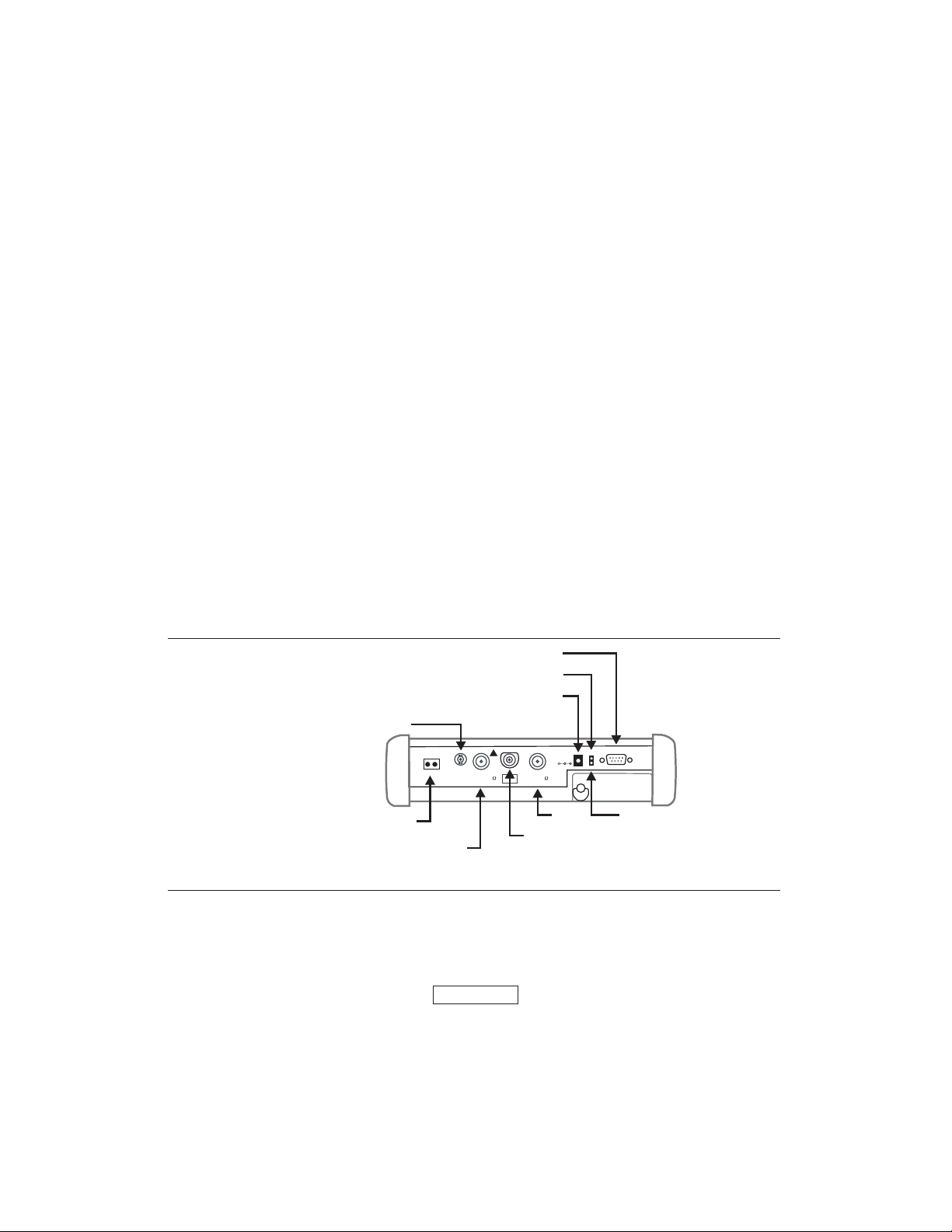
Test Connector Panel
The connectors and indicators located on the test panel (Figure 2-1) are listed and described
below. The illustration depicts an S331D with Option 50, T1/E1 installed.
ERIAL INTERFACE
EXTERNAL POWER LED
EXTERNAL POWER
EXTERNAL FREQ REF /
EXT TRIGGER
RECEIVE TRANSMIT
T1/E1
ExtFreq Ref / Ex t Trigger
+23dBm MAX 50VDC MAX
RF Out /
GPSAntenna
!
CAUTION
AVOIDSTATIC
DISCHARGE
SpectrumAnalyzer
RF In 50Reflection 50
+43dBm MAX 50VDC MAX
12.5- 15V DC
(1350mA)
ExternalPower
BatteryCharging
Serial
Interface
-
-
-
T1/E1 (S331D OPTION 50) or
FREQUENCY CONVERTER
POWER MONITOR DETECTOR
Figure 2-1. S331D Test Connector Panel (with Option 50)
12.5-15VDC
12.5 to 15 Vdc @ 3A input to power the unit or for battery charging.
(3A)
When using the AC-DC Adapter, always use a three-wire power cable connected
to a three-wire power line outlet. If power is supplied without grounding the equip
ment in this manner, there is a risk of receiving a severe or fatal electric shock, or
damaging the equipment.
www.valuetronics.com
(S332DOPTION6)or
(OPTION 5)
CONNECTOR
RF OUT
WARNING
RF IN
GPS ANTENNA
BATTERY
CHARGING
LED
-
2-1

Chapter 2 Functions and Operations
Battery
Charging
External
Power
Serial
Interface
RF Out/
Reflection 50W
Spectrum
Analyzer
RF In 50W
Ext Freq
Ref/Ext Trigger
GPS Antenna
(Option 31)
T1/E1
Receive/
Transmit
(Option 50)
Illuminates when the battery is being charged. The indicator automatically shuts
off when the battery is fully charged.
Illuminates when the Site Master is being powered by the external charging unit.
RS232 DB9 interface to a COM port on a personal computer (for use with the
Anritsu Handheld Software Tools program) or to a supported printer.
RF output, 50 W impedance, for reflection measurements. Maximum input is
+23 dBm at ±50 Vdc.
RF input, 50 W impedance, for spectrum analysis measurements. Maximum in
put is +43 dBm at ±50 Vdc.
Input for an external reference signal or trigger in Spectrum Analyzer mode.
GPS antenna connection. Do not connect anything other than the Anritsu GPS
antenna to this port.
Transmit and Receive connectors for T1 and E1 measurements (S331D only)
-
RF Detector
(Option 5)
Frequency
Converter
Interface
(Option 6)
Headphone
Jack
NOTE: For the Site Master S331D, Options 5 and 50 are mutually exclusive.
That is, the Site Master S331D can be configured with either Option 5, Power
Monitor, or Option 50, T1/E1, but not both.
For the Site Master S332D, Options 5 and 6 are mutually exclusive. That is, the
Site Master S332D can be configured with either Option 5, Power Monitor, or
Option 6, Frequency Converter Interface, but not both.
RF detector connector for Power Monitor measurements using an external
detector. Refer to the table of available RF Detectors on page 1-3.
Ten pin D-style connector providing an interface to control and communicate
with an Anritsu frequency conversion module (S332D only).
Provides audio output for the built-in AM/FM demodulator for testing and trou
bleshooting wireless communication systems.
-
2-2
www.valuetronics.com
Chapter 2 Functions and Operations
TITLE BAR
SSAG
TITLE BAR
SSAG
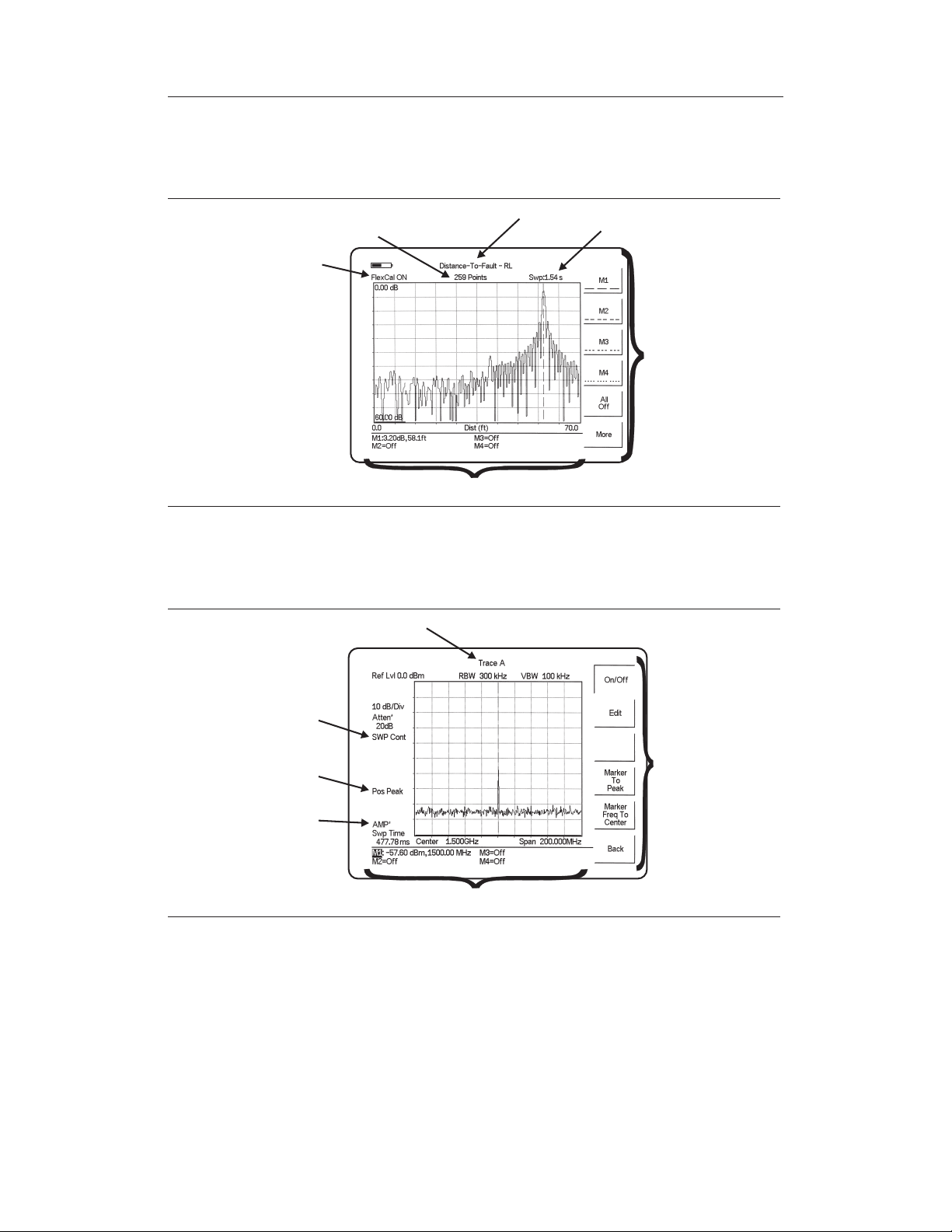
Display Overview
Figure 2-2 illustrates some of the key information areas of the S331D display.
DATA
POINTS
CALIBRATION
STATUS
ME
EAREA
Figure 2-2. S331D Display Overview
Figure 2-3 illustrates some of the key information areas of the S332D display.
SWEEP
TIME
CURRENT
MENU
SWEEP
MODE
DETECTION
METHOD
PREAMPLIFIER
STATE
Figure 2-3. S332D Display Overview
ME
CURRENT
MENU
EAREA
2-3
www.valuetronics.com
Chapter 2 Functions and Operations
Sof
y
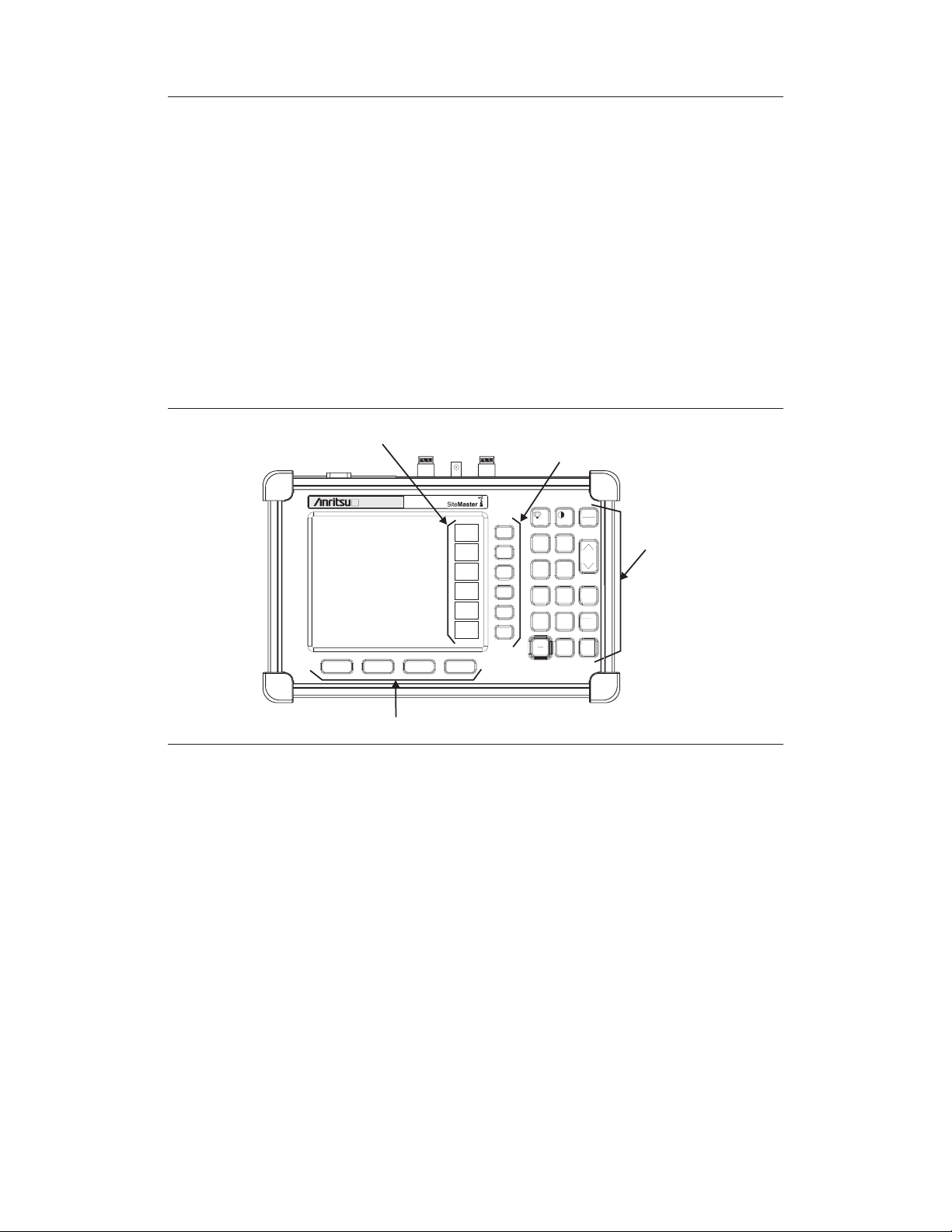
Front Panel Overview
The Site Master menu-driven user interface is easy to use and requires little training. Hard
keys on the front panel are used to initiate function-specific menus. There are four function
hard keys located below the status window: Mode, Frequency/Distance, Amplitude and
Measure/Display.
There are seventeen keypad hard keys located to the right of the status window. Twelve of
the keypad hard keys perform more than one function, depending on the current mode of
operation. The dual purpose keys are labeled with one function in black, the other in blue.
There are also six soft keys that change function depending upon the current mode selec
tion. The current soft key function is indicated in the soft key menu area to the right of the
status window. The locations of the different keys are illustrated in Figure 2-4.
tKey
Menu
Soft Keys
S332D
FREQ/DIST
MODE
Function Hard Ke
Figure 2-4. Site Master Front Panel
AMPLITUDE
MEAS/DISP
s
START
CAL
SAVE
SETUP
LIMIT
SAVE
DISPLAY
ESCAPE
CLEAR
2
1
AUTO
SCALE
3
4
RECALL
SETUP
6
5
MARKER
ENTER
8
7
RECALL
RUN
DISPLAY
HOLD
9
ON
OFF
+
0
-
/
PRINT
SYS
.
Keypad
Hard
Keys
-
The following sections describe the various key functions.
2-4
www.valuetronics.com

Chapter 2 Functions and Operations
Function Hard Keys
MODE Opens the mode selection box (below). Use the Up/Down arrow key to select a
mode. Press the ENTER key to implement.
o Measurement Mode
Freq - SWR
Return Loss
Cable Loss - One Port
DTF - SWR
Return Loss
Power Monitor (External Detector)
Power Meter (Internal)
High Accuracy Power Meter
Spectrum Analyzer
Interference Analyzer
T1 Tester
E1 Tester
Transmission Measurement
Channel Scanner
CW Signal Generator
Figure 2-5. Mode Selection Box
NOTE: Available mode selections will vary according to model number and op
tions installed.
FREQ/DIST Displays the Frequency or Distance to Fault soft key menus depending on the
measurement mode (see page 2-18).
AMPLITUDE Displays the amplitude soft key menu for the current operating mode (see page
2-20).
MEAS/DISP Displays the measurement and display soft key menus for the current operating
mode (see page 2-21).
-
www.valuetronics.com
2-5

Chapter 2 Functions and Operations
Keypad Hard Keys
This section contains an alphabetical listing of the Site Master front panel keypad controls
along with a brief description of each. More detailed descriptions of the major function
keys follow.
The following keypad hard key functions are printed in black on the keypad keys.
0-9 These keys are used to enter numerical data as required to setup or per
form measurements.
+/–
·
ESCAPE
CLEAR
Up/Down
Arrows
ENTER Implements the current action or parameter selection.
ON
OFF
The plus/minus key is used to enter positive or negative values as required
to setup or perform measurements.
The decimal point is used to enter decimal values as required to setup or
perform measurements.
Exits the present operation or clears the status window. If a parameter is
being edited, pressing this key will clear the value currently being entered
and restore the last valid entry. Pressing this key again will close the pa
rameter. During normal sweeping, pressing this key will move up one
menu level.
Increments or decrements a parameter value. The specific parameter value
affected typically appears in the message area of the LCD.
Turns the Anritsu Site Master on or off. When turned on, the saved system
state at the last turn-off is restored. If the ESCAPE/CLEAR key is held
down while the ON/OFF key is pressed, the factory preset state will be
restored.
-
-
SYS Allows selection of system and application setup parameters and the dis
play language.
2-6
-
www.valuetronics.com

Chapter 2 Functions and Operations
The following keypad hard key functions are printed in blue on the keypad keys.
This key is used to adust the display brightness. Use the Up/Down arrow
key and ENTER to adjust the brightness.
AUTO
SCALE
LIMIT Displays the limit line menu for the current operating mode when in cable,
MARKER Displays the marker menu of the current operating mode when in cable,
PRINT Prints the current display to the selected printer via the RS232 serial port.
RECALL
DISPLAY
RECALL
SETUP
RUN
HOLD
Automatically scales the status window for optimum resolution in cable
and antenna analyzer mode.
antenna analyzer or spectrum analyzer mode.
antenna analyzer or spectrum analyzer mode.
Recalls a previously saved trace from memory. When the key is pressed, a
Recall Trace selection box appears on the display. Select a trace using the
Up/Down arrow key and press the ENTER key to implement.
Recalls a previously saved setup from a memory location. When the key
is pressed, a Recall Setup selection box appears on the display. Select a
setup using the Up/Down arrow key and press the ENTER key to implement. Setup 0 recalls the factory preset state for the current mode.
When in the Hold mode, this key starts the Site Master sweeping and provides a Single Sweep Mode trigger; when in the Run mode, it pauses the
sweep. When in the Hold mode, the hold symbol (page 2-68) appears on
the display. Hold mode can be used to conserve battery power.
SAVE
DISPLAY
SAVE
SETUP
START
CAL
Saves up to 300 displayed traces to non-volatile memory. When the key is
pressed, the Trace Name: box appears. Use the soft keys to enter up to 16
alphanumeric characters for that trace name and press the ENTER key to
save the trace.
Saves the current system setup to an internal non-volatile memory loca
tion. The number of locations available varies with the model number and
installed options. There are ten available locations in cable and antenna
analyzer mode (S331D and S332D), and five in SPA mode (S332D only).
There are five available locations in Power Meter mode (Option 29,
S331D and S332D) and five each in T1/E1 modes (Option 50, S331D
only). When the key is pressed, a
status window. Use the Up/Down arrow key to select a setup and press the
ENTER key to implement.
Starts the calibration in SWR, Return Loss, Cable Loss, or DTF measure
ment modes (not available in Spectrum Analyzer or Power Meter modes).
Save Setup selection box appears on the
-
-
www.valuetronics.com
2-7
Chapter 2 Functions and Operations
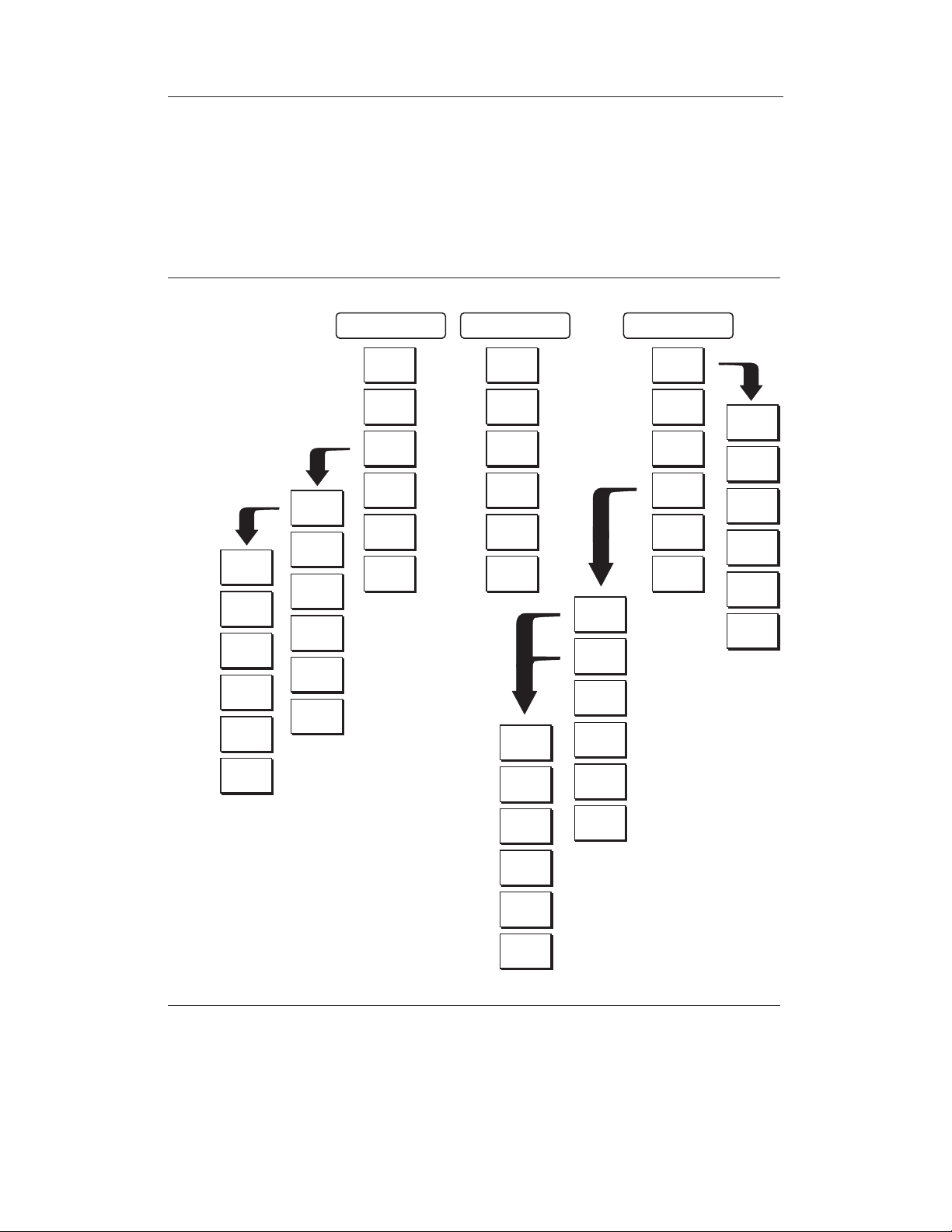
Soft Keys
Each keypad key opens a set of soft key selections. Each of the soft keys has a correspond
ing soft key label area on the status window. The label identifies the function of the soft key
for the current Mode selection.
The following figures show the soft key labels for each Mode selection.
ODE=Return Loss:
SOFTKEYS:
Standard
To p
of
List
Page
Up
Page
Down
Bottom
of
List
Select/
Deselect
Show
Selected
Downlink
Up+Down
FREQ/DIST
F1
F2
Signal
Standard
Select
Uplink
link
Back
AMPLITUDE
To p
Bottom
To p
of
List
Page
Up
MEAS/DISP
Resolution
Single
Sweep
Trace
Math
Trace
Overlay
Fixed
CW
On/Off
Select
Trace
-
130
259
517
Figure 2-6. Return Loss Mode Soft Key Labels
2-8
www.valuetronics.com
Page
Down
Bottom
of
List
Delete
Trace
Delete
All
Traces
Back
Chapter 2 Functions and Operations
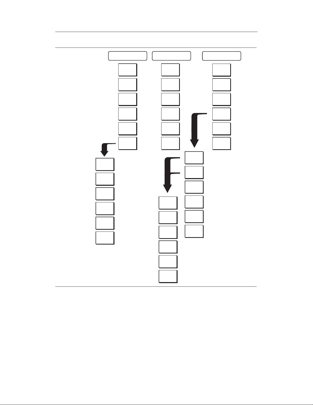
MODE=DTF:
SOFTKEYS:
Window
Loss
Prop
Vel
Cable
FREQ/DIST
D1
D2
DTF Aid
More
AMPLITUDE
Top
Bottom
Top
of
List
MEAS/DISP
Resolution
Single
Sweep
Trace
Math
Trace
Overlay
Fixed
CW
On/Off
Select
Trace
Back
Figure 2-7. Distance to Fault Mode Soft Key Labels
Page Up
Page
Down
Bottom
of
List
Delete
Trace
Delete
All
Traces
Back
www.valuetronics.com
2-9

Chapter 2 Functions and Operations
ODE=SPECTRUM ANALYZER:
SOFTKEYS:
Edit
Full
Zero
Span
Up
1-2-5
Span
Down
1-2-5
Back
Top
of
List
Page
Up
Page
Down
Bottom
of
List
Select/
Deselect
Increment
Select
Stan dard
Select
Channel
Uplink
Downlink
Channel
Back
FREQ/DIST
Center
Span
Star t
Stop
Signal
Stan da rd
dBm
dBV
dBmV
dBuV
BACK
AMPLITUDE
Ref
Level
Scale
Atten/
Preamp
Units
Ref
Level
Offset
Auto
Manual
Dynamic
Preamp
Control
Manual
Back
Auto
Manual
Dynamic
Figure 2-8. Spectrum Analyzer Mode Soft Key Labels (S332D only)
2-10
www.valuetronics.com
Show
Selected
Preamp
On/Off
Preamp
Auto
Back

Chapter 2 Functions and Operations
On/Off
MODE = SPECTRUM ANALYZER:
SOFTKEYS:
RBW
Auto
RBW
Manual
VBW
Auto
VBW
Manual
Back
Positive
Peak
RMS
Average
Negative
Peak
Sampling
Mode
Back
Max
Hold
Detec-
tion
Average
(2-25)
Trac e
Math
Min
Hold
Back
Recall
Trac e
-> B
View B /
Clear B
A-> B
A-B
->
A
A+B
->
A
Back
MEAS/DISP
Bandwidth
Trace
Measure
Trigg er
Min
Sweep
Time
Ref
Level
On/Off
Demod
Type
Demod
Freq
Volu me
Demod
Time
Back
Free
Run
Single
Recovered
Video
Change
Trig ger
Position
Back
Narrow
Band
FHSS
Wide
Band
FHSS
Broadband
Field
Strngt h
OBW
Channel
Power
ACPR
More
Back
Signal
Type
Center
Span
Min
Sweep
Time
Measure
Select
Standard
Antenna
Select
Custom
Antenna
Back
AM/FM
Demod
C/I
Back
Method
%
dBc
Measure
Back
Center
Freq
Main
Channel
BW
Adj
Channel
BW
Channel
Spacing
Measure
Back
Center
Freq
Int
BW
Channel
Span
Zoom
One
Channel
Measure
Back
Figure 2-9. Spectrum Analyzer Mode Soft Key Labels (S332D only) (continued)
www.valuetronics.com
Back
Back
2-11

Chapter 2 Functions and Operations
Auto
ODE=T1 Tester:
SOFTKEYS:
Start /
Stop
Measure
Terminate/
Bridged
Transmit
Vpp/
dBdsx
Back
Frequency
Transmit
Volume
Select
Channel
On/Off
Transmit
Level
Back
Setup
BERT
Vpp
VF
Channel
Access
(If Histogram
is selected)
Self
Loop
Up
Self
Loop
Down
Remote
Loop
Up
Remote
Loop
Down
Display
Raw Data/
Histogram
Start /
Stop
Measure
Insert
Errors
Measure
Duration
Time
Scale
More
Framing
Mode
Receive
Input
Pattern
Line
Coding
More
Back
0dB
-7.5 dB
D4 SF
ESF
Back
Clock
Source
Setup
Error
Insert
Loop
Code
Transmit
Level
ANSI CRC/
Japan CRC
Back
Terminate
Bridged
Monitor
+20 dB
Back
CSU
NIU
User 1
B8ZS
AMI
Back
Bit
BPV
Framing
Bits
RAI
Internal
External
Figure 2-10. T1 Tester Mode Soft Keys
2-12
www.valuetronics.com
Back
-15 dB
Back
User 2
In Band/
Data Link
Back
AIS
Back
Back

Chapter 2 Functions and Operations
Auto
ODE=T1 Tester:
SOFTKEYS:
Star t /
Stop
Measure
Terminate/
Bridged
75
120
Vpp/
dBdsx
Back
Volume
Select
Channel
Transmit
On/Off
Transmit
Frequency
Transmit
Level
Back
Setup
BERT
Vpp
VF
Channel
Access
(If Histogram
is selected)
Self
Loop
Up
Self
Loop
Down
Display
Raw Data/
Histogram
Star t /
Stop
Measure
Insert
Errors
Measure
Duration
Time
Scale
More
Framing
Mode
Receive
Input
Pattern
Line
Coding
More
Back
PCM30
PCM30
CRC
PCM31
PCM31
CRC
Back
Clock
Source
Setup
Error
Insert
Impedance
Terminate
Bridged
Monitor
+20 dB
Back
75
HDB3
AMI
Back
Bit
BPV
Internal
External
Figure 2-11. E1 Tester Mode Soft Keys
www.valuetronics.com
Back
Back
120
Back
Framing
Bits
RAI
AIS
Back
Back
2-13

Chapter 2 Functions and Operations
MODE = TRANSMISSIONMEASUREMENT
SOFTKEYS:
FREQ/SPAN
Center
Span
Start
Stop
Signal
Standar d
Select
Channel
AMPLITUDE
Edit
Full
Min
Span
Up
1-2-5
Span
Down
1-2-5
Back
Ref
Level
Scale
Atten/
Preamp
Auto
Manual
Dynamic
Preamp
Control
Manual
Back
MEAS/DISP
Bandwidth
Trace
Calibrate
TM
Auto
RBW
Auto
RBW
Manual
VBW
Auto
VBW
Manual
Back
Figure 2-12. Transmission Measurement Mode Soft Keys
2-14
Manual
Dynamic
Preamp
On/Off
Preamp
Auto
Back
www.valuetronics.com
Chapter 2 Functions and Operations
MODE=POWER METER:
SOFTKEYS:
Edit
Full
Zero
Span
Up
1-2-5
Span
Down
1-2-5
Back
Top
of
List
Page
Up
Page
Down
Bottom
of
List
Select/
Deselect
Show
Selected
Select
Standard
Select
Channel
Uplink
Downlink
Channel
Increment
Back
FREQ/DIST
Center
Span
Signal
Standard
AMPLITUDE
Figure 2-13. Power Meter Mode Soft Key Labels (Option 29)
Units
Rel
Offset
dB
Zero
Edit
Calibrate
Offset
Recall
Offset
CAL
Back
MEAS/DISP
RMS
Acquisition
Off
Low
Medium
High
Back
SOFTKEYS:
Top
of
List
Page
Up
Page
Down
Bottom
of
List
Select/
Deselect
Show
Selected
Select
Standard
Select
Channel
Uplink
Downlink
Back
FREQ/DIST
Center
Signal
Standard
AMPLITUDE
Rel
Offset
dB
Zero
MEAS/DISP
Figure 2-14. High Accuracy Power Sensor Mode (Option 19) Soft Keys
Running
Averages
Max
Hold
Limit
ON/OFF
Lower
Limit
Upper
Limit
Limit
Units
www.valuetronics.com
2-15

Chapter 2 Functions and Operations
Hour
Minute
Month
Day
Year
Back
Clock
Printer
Units
Change
Date
Format
Back
GPS
On/Off
Location
Quality
Reset
Back
System
Options
Application
Options
Self
Test
Status
GPS
Language
English
CAL
Mode
Back
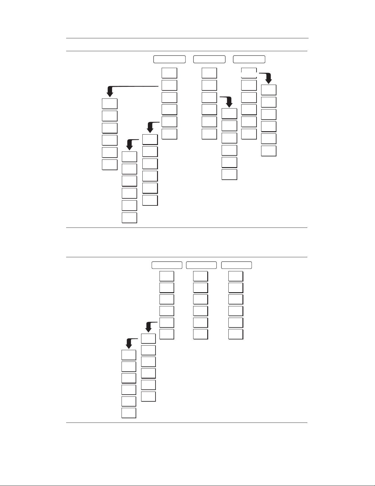
Figure 2-16. SYS Key Menu in Cable and Antenna Analyzer Mode
System
Options
Application
GPS
Back
Options
Self
Test
Stat us
GPS
Language
English
External
Freq
Bias
Impedance
Back
Hour
Minute
Month
Day
Yea r
Back
Clock
Printer
Units
Change
Date
Format
Back
On/Off
Location
Quality
Reset
Ref
Tee
50
75
__
Anritsu
12N50-75B
Other
Adapter
Offset
Back
Figure 2-15. SYS Key Menu in Spectrum Analyzer and Transmission Measurement Modes
2-16
www.valuetronics.com

Hour
Minute
Month
Day
Yea r
Back
Clock
Printer
Units
Change
Date
Format
Back
GPS
On/Off
Location
Quality
Reset
System
Options
Application
Options
Self
Test
Stat us
GPS
Language
English
Chapter 2 Functions and Operations
External
Ref
Freq
Bias
Tee
Impedance
50
75
__
Anritsu
12N50-75B
Back
Other
Adapter
Offset
Back
Figure 2-18. SYS Key Menu in Power Meter Mode (Option 29)
System
Options
Application
GPS
Options
Self
Test
Stat us
GPS
Language
English
Hour
Minute
Month
Day
Yea r
Back
Clock
Printer
Units
Change
Date
Format
Back
On/Off
Location
Quality
Log
Data
Back
Back
Figure 2-17. SYS Key in T1/E1 Mode (Option 50)
www.valuetronics.com
Reset
Back
2-17

Chapter 2 Functions and Operations
FREQ/DIST Displays the frequency and distance menu depending on the measurement mode.
Frequency
Menu
Distance
Menu
The frequency and distance menu for cable and antenna analyzer measurements
provides for setting sweep frequency end points when Freq mode is selected. Se
lected frequency values may be changed using the keypad or Up/Down arrow
key.
F1 — Opens the F1 parameter for data entry. This is the start value for the
q
frequency sweep. Press ENTER when data entry is complete.
F2 — Opens the F2 parameter for data entry. This is the stop value for the
q
frequency sweep. Press ENTER when data entry is complete.
Signal Standard — Allows selection of the signal standard to be used. Select
q
from the available international standards (Appendix C).
Provides for setting Distance to Fault parameters when a DTF mode is selected.
Choosing DIST causes the soft keys, below, to be displayed and the correspond
ing values to be shown in the message area. Selected distance values may be
changed using the keypad or Up/Down arrow key.
D1 — Opens the start distance (D1) parameter for data entry. This is the start
q
value for the distance range (D1 default = 0). Press ENTER when data entry
is complete.
D2 — Opens the end distance (D2) parameter for data entry. This is the end
q
value for the distance range. Press ENTER when data entry is complete.
q DTF Aid — Provides interactive help to optimize DTF set up parameters. Use
the Up/Down arrow key to select a parameter to edit. Press ENTER when
data entry is complete.
-
-
q More — Selects the Distance Sub-Menu, detailed below.
q
Loss — Opens the Cable Loss parameter for data entry. Enter the loss per
meter (or foot) for the type of transmission line being tested. Press
ENTER when data entry is complete. (Range is 0.5 to 5.0 dB/m, 1.524
dB/ft)
q
Prop Vel (relative propagation velocity) — Opens the Propagation Veloc
ity parameter for data entry. Enter the propagation velocity for the type of
transmission line being tested. Press ENTER when data entry is com
plete. (Range is 0.010 to 1.000)
q
Cable — Opens a list of cable three common coaxial folders (1000 MHz,
2000 MHz, and 2500 MHz) and one custom folder. Select either folder
and use the Up/Down arrow key and ENTER to make a selection. This
feature provides a rapid means of setting both cable loss and propagation
velocity. (Refer to Appendix A for a listing of common coaxial cables
showing values for Relative Propagation Velocity and Nominal Attenua
tion in dB/m or dB/ft @ 1000 MHz, 2000 MHz and 2500 MHz.) The cus
tom cable folder can consist of up to 49 user-defined cable parameters
uploaded via the Handheld Software Tools program.
q
Window — Opens a menu of FFT windowing types for the DTF calcula
tion. Scroll the menu using the Up/Down arrow key and make a selection
with the ENTER key. Refer to Appendix B for more details on window
ing.
-
-
-
-
-
-
2-18
www.valuetronics.com

Back — Returns to the Distance Menu.
q
Chapter 2 Functions and Operations
Choosing FREQ/DIST in Spectrum Analyzer mode causes the soft keys, below, to be dis
played and the corresponding values to be shown in the message area.
Center ¾ Sets the center frequency of the Spectrum Analyzer. Enter a value
q
using the Up/Down arrow key or keypad, press ENTER to accept, ESCAPE
to restore previous value.
Span ¾ Sets the user-defined frequency span. Use the Up/Down arrow key
q
or keypad to enter a value in MHz. Also brings up Full and Zero soft keys.
Edit allows editing of the frequency span. Enter a value using the number
q
keys.
Full span sets the Spectrum Analyzer to its maximum frequency span.
q
Zero span sets the span to 0 Hz. This displays the input signal in an ampli
q
tude versus time mode, which is useful for viewing modulation.
Span Up 1-2-5 activates the span function so that the span may be in
q
-
creased quickly in a 1-2-5 sequence.
Span Down 1-2-5 activates the span function so that the span may be re
q
duced quickly in a 1-2-5 sequence.
Back returns to the previous menu level.
q
q Start ¾ Sets the Spectrum Analyzer in the START-STOP mode. Enter a
start frequency value (in kHz, MHz, or GHz) using the Up/Down arrow key
or keypad, press ENTER to accept, ESCAPE to restore.
-
-
-
q Stop ¾ Sets the Spectrum Analyzer in the START-STOP mode. Enter a stop
frequency value (in kHz, MHz, or GHz) using the Up/Down arrow key or
keypad, press ENTER to accept, ESCAPE to restore.
q
Signal Standard ¾ Allows selection of the signal standard to be used. Select
from the available international standards. For more information, refer to Appendix C.
q
Select Channel ¾ Sets the channel information for the available standard
from a minimum of 0 to a maximum of 1199.
www.valuetronics.com
2-19

Chapter 2 Functions and Operations
AMPLITUDE Displays the amplitude or scale menu depending on the measurement mode.
Amplitude
Menu
Provides for changing the status window scale. Selected values may be changed
using the Up/Down arrow key or keypad.
Choosing AMPLITUDE in cable and antenna analyzer measurement modes
causes the soft keys, below, to be displayed and the corresponding values to be
shown in the message area.
Top — Opens the top parameter for data entry and provides for setting the
q
top scale value. Press ENTER when data entry is complete.
Bottom — Opens the bottom parameter for data entry and provides for setting
q
the bottom scale value. Press ENTER when data entry is complete.
Choosing AMPLITUDE in Spectrum Analyzer mode causes the soft keys, below,
to be displayed and the corresponding values to be shown in the message area.
Ref Level — Activates the amplitude reference level function. Valid refer
q
-
ence levels are from +20 to –120 dBm.
Scale — Activates the scale function in a 1 through 15 dB logarithmic ampli
q
tude scale. This soft key is not active if the units are set to linear.
Atten/Preamp — Sets the internal input attenuator so that it is either coupled
q
automatically to the reference level (Auto), manually adjustable (Manual), dynamically coupled to the input signal (Dynamic) and provides control for the
preamplifier.
q Auto — Sets the input attenuator so that it is coupled automatically to the
reference level.
-
q Manual — Sets the input attenuator manually from 0 to 51 dB.
q
Dynamic — Sets the input attenuator so that it is dynamically coupled to
the input signal and turns the preamp on or off as necessary.
q
Preamp Control Manual — Activates the preamp menu.
q
Preamp On/Off — Sets the preamplifier on or off.
q
Preamp Auto — Automatically adjusts the preamplifier according to
the reference level.
q
Back — Returns to the previous menu level.
q
Units — Choose from the menu of amplitude related units. When Linear is
selected, the available selections are Volts or Watts. When Log is selected,
the selection of dBm sets absolute decibels relative to 1 mW as the amplitude
unit. Selection of dBV, dBmV or dBmV sets absolute decibels relative to 1
volt, 1 millivolt, or 1 microvolt respectively as the amplitude unit.
q
Ref Level Offset — Sets the reference level offset. This feature allows mea
surement of high gain devices in combination with an attenuator. It is used to
offset the reference level to view the correct output level. For example, to
measure a high gain amplifier with an output of 70 dBm, an external 50 dB
attenuator must be inserted between the Site Master and the device. To com
pensate, set the reference level offset to –50 dB.
-
-
2-20
www.valuetronics.com

Chapter 2 Functions and Operations
MEAS/DISP Displays the Meas/Disp soft key menu for the current operating mode.
Meas/Disp
Menu
Provides for changing the status window resolution, single or continuous sweep,
and access to the Trace Math functions.
Choosing MEAS/DISP in cable and antenna analyzer freq or DTF measurement
modes causes the soft keys below to be displayed.
Resolution — Opens the status window to change the resolution. Choose 130,
q
259, or 517 data points. (In DTF mode, resolution can only be adjusted
through the DTF Aid table.)
Single Sweep — Toggles the sweep between single sweep and continuous
q
sweep. In single sweep mode, each sweep must be activated by the
RUN/HOLD button.
Trace Math — Opens up the Trace Math functions (trace-memory or
q
trace+memory) for comparison of the real time trace in the status window
with any of the traces from memory. (Not available in DTF mode.)
Trace Overlay — Opens up the Trace Overlay functions menu to allow the
q
current trace to be displayed with a trace in memory overlaid on it. Choose
On or Off and Select Trace to select the trace from memory to be overlaid.
Fixed CW — Toggles the fixed CW function ON or OFF. When OFF, a nar
q
row band of frequencies around the selected frequency is generated. This enhances the immunity of the Site Master to an interfering signal. When CW is
ON, only a single frequency with a very narrow band width is generated by
the Site Master. The sweep speed is somewhat faster in CW ON mode. If CW
is ON during normal RL or SWR measurements, it will be more susceptible
to interfering signals, so use this feature with caution. Interfering signals can
make the measurement look better or worse than it really is.
Choosing MEAS/DISP in
Spectrum Analyzer mode causes the soft keys below
to be displayed.
q
Bandwidth — Activates a menu that allows the resolution and video
bandwidths to be either coupled automatically to the span (Auto) or manually
adjustable (Manual).
q
RBW Auto — Sets the resolution bandwidth so that it is automatically
coupled to the span.
q
RBW Manual — Sets the resolution bandwidth manually, independent of
the span.
q
VBW Auto — Sets the video bandwidth so that it is automatically coupled
to the RBW.
q
VBW Manual — Sets the video bandwidth manually, independent of the
RBW.
q
Back — Returns to the previous menu level.
q
Trace — Activates a menu of trace related functions. Use the corresponding
soft key to select the desired trace function.
q
Max Hold — Displays and holds the maximum responses of the input sig
nal.
q
Detection — Accesses a menu of detector modes including Positive Peak
detection, RMS Average detection, Negative Peak detection, and Sam
pling Mode.
-
-
www.valuetronics.com
2-21

Chapter 2 Functions and Operations
Positive Peak — The unit reads and displays the highest measured
q
data point within a display point.
RMS Average — The unit reads and displays the RMS average of the
q
measured data. RMS average is calculated by taking the log of the av
erage power within a display point and the power is calculated from
the voltage.
Negative Peak — The unit reads and displays the lowest measured
q
data point within a display point.
Sampling Mode — The unit reads and displays a sampled measured
q
point at each display point.
Average (2-25) — The display will be an average of the number of sweeps
q
specified here. For example, if the number four is entered here, the data
displayed will be an average of the four most recent sweeps.
Trace Math — Opens up the Trace Math functions for comparison of the
q
real time trace in the graph with any of the traces from memory.
Recall Trace –> B — Recalls the selected saved trace to trace B.
q
View B / Clear B — Views the recalled trace as trace B, or clears trace
q
B from the status window.
A–>B— Moves trace A to trace B.
q
A–B–>A— Moves the results of trace A minus trace B to trace A.
q
A+B–>A— Moves the results of trace A plus trace B to trace A.
q
q Back — Returns to the previous menu level.
-
q Min Hold — Displays and holds the minimum responses of the input sig-
nal.
q Back — Returns to the previous menu level.
q Measure — Activates a menu of measurement related functions. Use the cor-
responding soft key to select the measurement function.
q
Field Strength — Accesses a menu of field strength measurement options.
q
On/Off — Turns field strength measurements on or off.
q
Select Standard Antenna — Select from the list of antenna profiles
provided.
q
Select Custom Antenna — Select a custom antenna profile as up
-
loaded to the Site Master using the Handheld Software Tools program.
q
Back — Returns to the previous menu.
q
OBW — Activates the occupied bandwidth menu.
q
Method — Allows selection of either % of power or dB Down.
q
% — Allows entry of the desired % of occupied bandwidth to be mea
sured.
q
dBc — Allows entry of the desired power level (dBc) to be measured.
q
Measure — Enables and disables the OBW measurement.
q
Back — Returns to the previous menu level.
q
Channel Power — Activates Channel Power measurement. Channel
power is measured in dBm. Channel Power density is measured in
dBm/Hz. The displayed units is determined by the setting of the Units soft
key in the AMPLITUDE menu.
-
2-22
www.valuetronics.com

Chapter 2 Functions and Operations
Center Freq - Activates the center frequency function and sets the Site
q
Master to the center frequency. A specific center frequency can be en
tered using the keypad or Up/Down arrow key.
Int BW — Enter the integration bandwidth frequency appropriate for
q
the application. Integration bandwidth must be at least one tenth of the
channel span.
Channel Span — Sets the channel span to a value appropriate for the
q
application.
Zoom One Channel — Automatically sets the span to cover one chan
q
nel as defined by the selected signal standard.
Measure — Enables and disables the channel power measurement.
q
Back — Returns to the previous menu level.
q
ACPR — Accesses a menu of Adjacent Channel Power Ratio measure
q
ment options:
Center Freq - Activates the center frequency function and sets the Site
q
Master to the center frequency. A specific center frequency can be en
tered using the keypad or Up/Down arrow key.
Main Channel BW - Sets the bandwidth of the main channel.
q
Adjacent Channel BW - Sets the bandwidth of the adjacent channel.
q
Channel Spacing - Sets the channel spacing.
q
Measure -Enables and disables the ACPR measurement.
q
Back - Returns to the previous menu.
q
q More — Opens more measurement menus in spectrum analyzer mode.
-
-
-
-
q Int. Analysis — Opens the interference analysis measurement menu.
q Set IA Freq. — Set the interference analysis frequency from 9 kHz
to 3000 MHz to measure the interference.
q
Measure — Measures the interference.
q
IA Freq. To Center — Set the interference analysis frequency to
the center of the interference frequency.
q
IA Freq as Marker M1 — Set the interference analysis frequency as
marker M1.
q
Back — Returns to the previous menu.
q
AM/FM Demod — Select AM, Narrow Band FM (300 ms de-empha
sis), Wide Band FM (50 ms de-emphasis), USB or LSB.
q
On/Off — Turns AM/FM Demodulation on or off.
q
Demod Type — Select either AM, FM Wide Band, FM Narrow
Band, SSB Lower or SSB Upper demodulation.
q
Demod Freq — Use the Up/Down arrow key or the keypad to in
crease or decrease the demodulation frequency. Select the GHz,
MHz, kHz,orHz soft key to accept the frequency input.
q
Volume — The current volume setting is displayed at the lower
right of the screen. Use the Up/Down arrow key to increase or de
crease the volume, and press the ENTER key to select.
q
Demod Time — Use the Up/Down arrow key or the keypad to in
crease or decrease the demodulation time, and press the ENTER
key to select.
q
Back — Returns to the previous menu.
-
-
-
-
www.valuetronics.com
2-23

Chapter 2 Functions and Operations
C/I — Opens carrier to interference measurement menu.
q
Signal Type - Opens a menu to select the signal type. Selections
q
are narrow band FHSS, wide band FHSS or a broadband signal.
Center - Activates the center frequency function and sets the Site
q
Master to the center frequency. A specific center frequency can be
entered using the keypad or Up/Down arrow key.
Span - Sets the user-defined frequency span. Use the Up/Down ar
q
row key or keypad to enter a value in MHz.
Min Sweep Time - Sets a sweep time of one second or more to im
q
prove the ability to capture instances of the interfering signal.
Measure - Starts the carrier to interference measurement.
q
Back - Returns to the previous menu.
q
Back — Returns to the previous menu.
q
Trigger — Select the method used to trigger the sweep.
q
Free Run — The sweep is continuous.
q
Single — A single sweep will be performed with each press of the
q
Run/Hold key.
Video — Sets the video trigger level if the span is set to zero.
q
Change Trigger Position — Changes the trigger sweep position from
q
5 msec to 2000 msec.
-
-
MARKER
q Back - Returns to the previous menu.
Choosing MARKER in cable and antenna analyzer freq and dist mode causes
the soft keys, below, to be displayed and the corresponding values to be shown
in the message area. Selected frequency marker or distance marker locations
may be changed using the keypad or Up/Down arrow key.
q
M1 — Selects the M1 marker parameter and opens the M1 marker second
level menu.
q
On/Off — Turns the selected marker on or off.
q
Edit — Opens the selected marker parameter for data entry. Press
ENTER when data entry is complete or ESCAPE to restore the previous
value.
q
Marker To Peak — Places the selected marker at the frequency or dis
-
tance with the maximum amplitude value.
q
Marker To Valley — Places the selected marker at the frequency or dis
-
tance with the minimum amplitude value.
q
Back — Returns to the Main Markers Menu.
q
M2 through M4 — Selects the marker parameter and opens the marker second
level menu.
q
On/Off — Turns the selected marker on or off.
q
Edit — Opens the selected marker parameter for data entry. Press
ENTER when data entry is complete or ESCAPE to restore the previous
value.
q
2-24
www.valuetronics.com
Delta (Mx-M1) — Displays delta amplitude value as well as delta fre
-
quency or distance for the selected marker with respect to the M1 marker.

Chapter 2 Functions and Operations
Marker To Peak — Places the selected marker at the frequency or dis
q
tance with the maximum amplitude value.
Marker To Valley — Places the selected marker at the frequency or dis
q
tance with the minimum amplitude value.
Back — Returns to the Main Markers Menu.
q
All Off — Turns all markers off.
q
More — Opens the continuation of the Marker Menus.
q
M5 — Selects the M5 marker parameter and opens the M5 second level
q
menu.
On/Off — Turns the selected marker on or off.
q
Edit — Opens the selected marker parameter for data entry. Press
q
ENTER when data entry is complete or ESCAPE to restore the pre
vious value.
Peak Between M1 & M2 — Places the selected marker at the fre
q
quency or distance with the maximum amplitude value between
marker M1 and marker M2.
Valley Between M1 & M2 — Places the selected marker at the fre
q
quency or distance with the minimum amplitude value between
marker M1 and marker M2.
Back — Returns to the Main Markers Menu.
q
M6 — Selects the M6 marker parameter and opens the M6 second level
q
menu.
-
-
-
-
-
q On/Off — Turns the selected marker on or off.
q Edit — Opens the selected marker parameter for data entry. Press
ENTER when data entry is complete or ESCAPE to restore the previous value.
q
Peak Between M3 & M4 — Places the selected marker at the peak be-
tween marker M3 and marker M4.
q
Valley Between M3 & M4 — Places the selected marker at the valley
between marker M3 and marker M4.
q
Back — Returns to the Main Markers Menu.
q
All Off —Turns all markers off
q
Back — Returns to the Main Markers Menu.
Choosing MARKER in Spectrum Analyzer mode causes the soft keys, below, to
be displayed and the corresponding values to be shown in the message area.
q
M1 — Selects the M1 marker parameter and opens the M1 marker second
level menu.
q
On/Off — Turns the selected marker on or off.
q
Edit — Opens the selected marker parameter for data entry. Press
ENTER when data entry is complete or ESCAPE to restore the previous
value.
q
q
www.valuetronics.com
Marker To Peak — Places the selected marker at the frequency with the
maximum amplitude value.
Marker Freq To Center — Makes the center frequency of the Site Master
equal to the frequency of the selected marker.
2-25

Chapter 2 Functions and Operations
Back — Returns to the Main Markers Menu.
q
M2 through M4 — Selects the marker parameter and opens the marker second
q
level menu.
On/Off — Turns the selected marker on or off.
q
Edit — Opens the selected marker parameter for data entry. Press
q
ENTER when data entry is complete or ESCAPE to restore the previous
value.
Delta (Mx-M1) — Displays delta amplitude value as well as delta fre
q
quency for the selected marker with respect to the M1 marker.
Marker To Peak — Places the selected marker at the frequency with the
q
maximum amplitude value.
Marker Freq To Center — Makes the center frequency of the Site Master
q
equal to the frequency of the selected marker.
Back — Returns to the Main Markers Menu.
q
All Off — Turns all markers off.
q
More — Opens the continuation of the Marker Menus.
q
M5 — Selects the M5 marker parameter and opens the M5 second level
q
menu.
On/Off — Turns the selected marker on or off.
q
q Edit — Opens the selected marker parameter for data entry. Press
ENTER when data entry is complete or ESCAPE to restore the previous value.
q Marker Freq To Center — Makes the center frequency of the Site
Master equal to the frequency of the selected marker.
q Peak Between M1 & M2 — Places the selected marker at the fre-
quency with the maximum amplitude value between marker M1 and
marker M2.
q
Valley Between M1 & M2 — Places the selected marker at the fre
quency with the minimum amplitude value between marker M1 and
marker M2.
q
Back — Returns to the Main Markers Menu.
-
-
q
2-26
www.valuetronics.com
M6 — Selects the M6 marker parameter and opens the M6 second level
menu.
q
On/Off — Turns the selected marker on or off.
q
Edit — Opens the selected marker parameter for data entry. Press
ENTER when data entry is complete or ESCAPE to restore the pre
vious value.
q
Marker Freq To Center — Makes the center frequency of the Site
Master equal to the frequency of the selected marker.
q
Peak Between M3 & M4 — Places the selected marker at the fre
quency with the maximum amplitude value between marker M3 and
marker M4.
q
Valley Between M3 & M4 — Places the selected marker at the fre
quency with the minimum amplitude value between marker M3 and
marker M4.
q
Back — Returns to the Main Markers Menu.
-

Chapter 2 Functions and Operations
Regular Marker — Measures the signal level at the point of the marker in
q
the unit type selected in the Amplitude - Units menu. When the regular
marker option is selected, all markers are regular markers.
Noise Marker — Measures noise level normalized toa1Hzbandwidth.
q
The unit of measure is dBm/Hz only. When Noise Marker is selected, the
detection type is automatically changed to RMS average. When the Noise
Marker option is selected, all markers are noise markers.
All Off — Turns all markers off.
q
Back — Returns to the Main Markers Menu.
q
LIMIT
Pressing LIMIT in cable and antenna analyzer frequency and distance mode acti
vates a menu of limit related functions. Use the corresponding soft key to select
the desired limit function. Then use the Up/Down arrow key to change its value,
which is displayed in the message area at the bottom of the status window.
Choosing LIMIT in
Freq or DTF measurement modes causes the soft keys below
to be displayed.
Single Limit — Sets a single limit value in dBm. Menu choices are:
q
On/Off — Turns the single limit function on or off
q
Edit — Allows entry of the limit amplitude.
q
Back — Returns to the previous menu.
q
q Multiple Limits — Sets multiple user defined limits, and can be used to create
a limit mask for quick pass/fail measurements.
q Segment 1 through Segment 5 — Opens the segment menu.
q On/Off — Turns the segment on or off.
q Edit — Opens the parameter for data entry.
q
Prev Segment — Edit or view the parameters of the previous seg-
ment.
q
Next Segment — Edit or view the parameters of the next segment. If
the next segment is off when this button is pressed, the starting point
of the next segment will be set equal to the ending point of the current
segment.
q
Back — Returns to the previous menu.
q
Back — Returns to the previous menu.
q
Limit Beep — Turns the audible limit beep indicator on or off.
-
Choosing LIMIT in Spectrum Analyzer measurement mode causes the soft keys
below to be displayed.
q
Single Limit — Sets a single limit value in dBm. Menu choices are:
q
q
q
q
www.valuetronics.com
On/Off — Turns the limit on or off.
Edit — Opens the parameter for data entry.
Upper / Lower Limit — Activate the upper and lower limit lines by tog
gling this soft key. The unit beeps if the data is above or below the set
limit lines and the status is displayed in the message area.
Back — Returns to the previous menu.
2-27
-

Chapter 2 Functions and Operations
Multiple Upper Limits — Sets multiple user-defined upper limits, and can be
q
used to create an upper limit mask for quick pass/fail measurements. An up
per limit will result in a failure when the data falls above the limit line. Menu
choices are:
Segment 1 through Segment 5 — Opens the segment menu.
q
On/Off — Turns the segment on or off.
q
Edit — Opens the parameter for data entry.
q
Prev Segment — Edit or view the parameters of the previous seg
q
ment.
Next Segment — Edit or view the parameters of the next segment. If
q
the next segment is off when this button is pressed, the starting point
of the next segment will be set equal to the ending point of the current
segment.
Back — Returns to the previous menu.
q
Back — Returns to the previous menu.
q
Multiple Lower Limits — Set multiple user defined lower limits, and can be
q
used to create a lower limit mask for quick pass/fail measurements. A lower
limit will result in a failure when the data falls below the limit line. Menu
choices are:
Segment 1 through Segment 5 — Opens the segment menu.
q
On/Off — Turns the segment on or off.
q
q Edit — Opens the parameter for data entry.
q Prev Segment — Edit or view the parameters of the previous seg-
ment.
q Next Segment — Edit or view the parameters of the next segment. If
the next segment is off when this button is pressed, the starting point
of the next segment will be set equal to the ending point of the current
segment.
q
Back — Returns to the previous menu.
-
-
2-28
q
Back — Returns to the previous menu.
q
Limit Beep — Turns the audible limit beep indicator on or off.
www.valuetronics.com

Chapter 2 Functions and Operations
SYS
In cable and antenna analyzer or optional power meter mode, pressing the SYS
key displays the following System menu soft key selections:
System Options — Displays a second level of system option functions:
q
Clock — Displays a second level of functions:
q
Hour — Enter the hour (0-23) using the Up/Down arrow key or the
q
keypad. Press ENTER when data entry is complete or ESCAPE to
restore the previous value.
Minute — Enter the minute (0-59) using the Up/Down arrow key or
q
the keypad. Press ENTER when data entry is complete or ESCAPE
to restore the previous value.
Month — Enter the month (1-12) using the Up/Down arrow key or the
q
keypad. Press ENTER when data entry is complete or ESCAPE to
restore the previous value.
Day — Enter the day using the Up/Down arrow key or the keypad.
q
Press ENTER when data entry is complete or ESCAPE to restore the
previous value.
Year — Enter the year (2003-2036) using the Up/Down arrow key or
q
the keypad. Press ENTER when data entry is complete or ESCAPE
to restore the previous value.
Back — Returns to the top-level SYS menu.
q
Printer — Displays a menu of supported printers. Use the Up/Down arrow
q
key and ENTER key to make the selection.
Units — Select the unit of measurement (metric or English).
q
q Change Date Format — Toggles the date format between
MM/DD/YYYY, DD/MM/YYYY, and YYYY/MM/DD.
q Back — Returns to the top-level SYS menu.
q Application Options — Application options displays options applicable to par-
ticular mode.
q
CAL Mode — In cable and antenna analyzer modes, selects either OSL
Cal or FlexCalä. FlexCal is a broadband frequency calibration valid from
25 MHz to 4 GHz. Refer to Calibration, page 3-2, for more information.
q
Back — Returns to the top-level SYS menu.
q
Self Test — Start an instrument self test.
q
Status — In cable and antenna analyzer freq or dist measurement mode, dis
-
plays the current instrument status, including calibration status, temperature,
and battery charge state. Press ESCAPE to return to operation.
q
GPS — Opens the GPS soft key menu.
q
Press the GPS On/Off soft key to turn the GPS feature on or off.
q
Press the Location soft key to view the latitude, longitude and altitude in
-
formation and UTC timing.
q
Press the Quality soft key to display the number of tracked satellites and
the GPS quality.
q
Press the Reset soft key to reset the GPS.
q
q
Language — Pressing this soft key immediately changes the language used to
display messages on the Site Master status window. Choices are English,
www.valuetronics.com
Back — Returns to the previous menu.
2-29

Chapter 2 Functions and Operations
French, German, Spanish, Chinese, and Japanese. The default language is
English.
In Spectrum Analyzer mode, pressing the SYS key displays the following Sys
tem menu soft key selections:
System Options — Displays a second level of system option functions:
q
Clock — Displays a second level of functions:
q
Hour — Enter the hour (0-23) using the Up/Down arrow key or the
q
keypad. Press ENTER when data entry is complete or ESCAPE to
restore the previous value.
Minute — Enter the minute (0-59) using the Up/Down arrow key or
q
the keypad. Press ENTER when data entry is complete or ESCAPE
to restore the previous value.
Month — Enter the month (1-12) using the Up/Down arrow key or the
q
keypad. Press ENTER when data entry is complete or ESCAPE to
restore the previous value.
Day — Enter the day using the Up/Down arrow key or the keypad.
q
Press ENTER when data entry is complete or ESCAPE to restore the
previous value.
Year — Enter the year (2003-2036) using the Up/Down arrow key or
q
the keypad. Press ENTER when data entry is complete or ESCAPE
to restore the previous value.
q Back — Returns to the top-level SYS menu.
q Printer — Displays a menu of supported printers. Use the Up/Down arrow
key and ENTER key to make the selection.
q Units — Select the unit of measurement (metric or English).
-
q Change Date Format — Toggles the date format between
MM/DD/YYYY, DD/MM/YYYY, and YYYY/MM/DD.
q
Back — Returns to the top-level SYS menu.
q
Application Options — Application options displays options applicable to par
ticular mode.
q
External Ref Freq — Set the external reference frequency from 2 MHz to
20 MHz.
q
Bias Tee — Selects Bias Tee on or off.
q
Impedance — Sets the input impedance of the instrument
q
50W — Sets the input impedance of the instrument to 50W, which is
the default setting.
q
75W Anritsu 12N50-75B — Displays measurements as if the input
impedance was 75W. The actual input impedance is still 50W, but the
displayed information is transformed to the equivalent 75W value
based on the offset value specified by the adapter used in the measure
ment. This setting is commonly used for cable TV-related measure
ments. Pressing this soft key will also compensate 7.5 dB for the loss
of the Anritsu 12N50-75B adapter.
q
Other adapter Offset — This key allows the user to enter other adapter
offset values. Enter the desired loss using the keypad or Up/Down ar
row key and press the ENTER key to accept.
q
Back — Returns to the previous menu.
-
-
-
-
q
2-30
www.valuetronics.com
Back — Returns to the top-level SYS menu.

Chapter 2 Functions and Operations
Self Test — Start an instrument self test.
q
Status — In cable and antenna analyzer freq or dist measurement mode, dis
q
plays the current instrument status, including calibration status, temperature,
and battery charge state. Press ESCAPE to return to operation.
GPS — Opens the GPS soft key menu.
q
Press the GPS On/Off soft key to turn the GPS feature on or off.
q
Press the Location soft key to view the latitude, longitude and altitude in
q
formation and UTC timing.
Press the Quality soft key to display the number of tracked satellites and
q
the GPS quality.
Press the Reset soft key to reset the GPS.
q
Back — Returns to the previous menu.
q
Language — Pressing this soft key immediately changes the language used to
q
display messages on the Site Master status window. Choices are English,
French, German, Spanish, Chinese, and Japanese. The default language is
English.
-
-
In Transmission Measurement mode, pressing the SYS key displays the follow
ing System menu soft key selections:
System Options — Displays a second level of system option functions:
q
Clock — Displays a second level of functions:
q
q Hour — Enter the hour (0-23) using the Up/Down arrow key or the
keypad. Press ENTER when data entry is complete or ESCAPE to
restore the previous value.
q Minute — Enter the minute (0-59) using the Up/Down arrow key or
the keypad. Press ENTER when data entry is complete or ESCAPE
to restore the previous value.
q
Month — Enter the month (1-12) using the Up/Down arrow key or the
keypad. Press ENTER when data entry is complete or ESCAPE to
restore the previous value.
q
Day — Enter the day using the Up/Down arrow key or the keypad.
Press ENTER when data entry is complete or ESCAPE to restore the
previous value.
q
Year — Enter the year (2003-2036) using the Up/Down arrow key or
the keypad. Press ENTER when data entry is complete or ESCAPE
to restore the previous value.
q
Back — Returns to the top-level SYS menu.
q
Printer — Displays a menu of supported printers. Use the Up/Down arrow
key and ENTER key to make the selection.
q
Units — Select the unit of measurement (metric or English).
-
q
q
q
Application Options — Application options displays options applicable to par
ticular mode.
q
www.valuetronics.com
Change Date Format — Toggles the date format between
MM/DD/YYYY, DD/MM/YYYY, and YYYY/MM/DD.
Back — Returns to the top-level SYS menu.
-
External Ref Freq — Set the external reference frequency from 2 MHz to
20 MHz.
2-31

Chapter 2 Functions and Operations
Bias Tee — Selects Bias Tee on or off.
q
Impedance — Sets the input impedance of the instrument
q
50W — Sets the input impedance of the instrument to 50W, which is
q
the default setting.
75W Anritsu 12N50-75B — Displays measurements as if the input
q
impedance was 75W. The actual input impedance is still 50W, but the
displayed information is transformed to the equivalent 75W value
based on the offset value specified by the adapter used in the measure
ment. This setting is commonly used for cable TV-related measure
ments. Pressing this soft key will also compensate 7.5 dB for the loss
of the Anritsu 12N50-75B adapter.
Other adapter Offset — This key allows the user to enter other adapter
q
offset values. Enter the desired loss using the keypad or Up/Down ar
row key and press the ENTER key to accept.
Back — Returns to the previous menu.
q
Back — Returns to the top-level SYS menu.
q
Self Test — Start an instrument self test.
q
-
-
-
Status — In cable and antenna analyzer freq or dist measurement mode, dis
q
plays the current instrument status, including calibration status, temperature,
and battery charge state. Press ESCAPE to return to operation.
GPS — Opens the GPS soft key menu.
q
Press the GPS On/Off soft key to turn the GPS feature on or off.
q
q Press the Location soft key to view the latitude, longitude and altitude in-
formation and UTC timing.
q Press the Quality soft key to display the number of tracked satellites and
the GPS quality.
q
Press the Reset soft key to reset the GPS.
q
Back — Returns to the previous menu.
q
Language — Pressing this soft key immediately changes the language used to
display messages on the Site Master status window. Choices are English,
French, German, Spanish, Chinese, and Japanese. The default language is
English.
In T1/E1 measurement mode, pressing the SYS key displays the following Sys
tem menu soft key selections:
q
System Options — Displays a second level of system option functions:
q
Clock — Displays a second level of functions:
q
Hour — Enter the hour (0-23) using the Up/Down arrow key or the
keypad. Press ENTER when data entry is complete or ESCAPE to
restore the previous value.
q
Minute — Enter the minute (0-59) using the Up/Down arrow key or
the keypad. Press ENTER when data entry is complete or ESCAPE
to restore the previous value.
q
Month — Enter the month (1-12) using the Up/Down arrow key or the
keypad. Press ENTER when data entry is complete or ESCAPE to
restore the previous value.
q
Day — Enter the day using the Up/Down arrow key or the keypad.
Press ENTER when data entry is complete or ESCAPE to restore the
previous value.
-
-
2-32
www.valuetronics.com

Chapter 2 Functions and Operations
Year — Enter the year (2003-2036) using the Up/Down arrow key or
q
the keypad. Press ENTER when data entry is complete or ESCAPE
to restore the previous value.
Back — Returns to the top-level SYS menu.
q
Printer — Displays a menu of supported printers. Use the Up/Down arrow
q
key and ENTER key to make the selection.
Units — Select the unit of measurement (metric or English).
q
Change Date Format — Toggles the date format between
q
MM/DD/YYYY, DD/MM/YYYY, and YYYY/MM/DD.
Back — Returns to the top-level SYS menu.
q
Application Options — Application options displays options applicable to par
q
ticular mode.
Log Data — Logs the data.
q
Back — Returns to the top-level SYS menu.
q
Self Test — Start an instrument self test.
q
-
Status — In cable and antenna analyzer freq or dist measurement mode, dis
q
plays the current instrument status, including calibration status, temperature,
and battery charge state. Press ESCAPE to return to operation.
GPS — Opens the GPS soft key menu.
q
q Press the GPS On/Off soft key to turn the GPS feature on or off.
q Press the Location soft key to view the latitude, longitude and altitude in-
formation and UTC timing.
q Press the Quality soft key to display the number of tracked satellites and
the GPS quality.
q Press the Reset soft key to reset the GPS.
q
Back — Returns to the previous menu.
q
Language — Pressing this soft key immediately changes the language used to
display messages on the Site Master status window. Choices are English,
French, German, Spanish, Chinese, and Japanese. The default language is
English.
In Power Monitor mode, pressing the SYS key displays the following System
menu soft key selections:
q
System Options — Displays a second level of system option functions:
q
Clock — Displays a second level of functions:
q
Hour — Enter the hour (0-23) using the Up/Down arrow key or the
keypad. Press ENTER when data entry is complete or ESCAPE to
restore the previous value.
q
Minute — Enter the minute (0-59) using the Up/Down arrow key or
the keypad. Press ENTER when data entry is complete or ESCAPE
to restore the previous value.
q
Month — Enter the month (1-12) using the Up/Down arrow key or the
keypad. Press ENTER when data entry is complete or ESCAPE to
restore the previous value.
q
Day — Enter the day using the Up/Down arrow key or the keypad.
Press ENTER when data entry is complete or ESCAPE to restore the
previous value.
-
www.valuetronics.com
2-33

Chapter 2 Functions and Operations
Year — Enter the year (2003-2036) using the Up/Down arrow key or
q
the keypad. Press ENTER when data entry is complete or ESCAPE
to restore the previous value.
Back — Returns to the top-level SYS menu.
q
Printer — Displays a menu of supported printers. Use the Up/Down arrow
q
key and ENTER key to make the selection.
Units — Select the unit of measurement (metric or English).
q
Change Date Format — Toggles the date format between
q
MM/DD/YYYY, DD/MM/YYYY, and YYYY/MM/DD.
Back — Returns to the top-level SYS menu.
q
Self Test — Start an instrument self test.
q
Status — In cable and antenna analyzer freq or dist measurement mode, dis
q
-
plays the current instrument status, including calibration status, temperature,
and battery charge state. Press ESCAPE to return to operation.
GPS — Opens the GPS soft key menu.
q
Press the GPS On/Off soft key to turn the GPS feature on or off.
q
Press the Location soft key to view the latitude, longitude and altitude in
q
-
formation and UTC timing.
Press the Quality soft key to display the number of tracked satellites and
q
the GPS quality.
q Press the Reset soft key to reset the GPS.
q Back — Returns to the previous menu.
q Language — Pressing this soft key immediately changes the language used to
display messages on the Site Master status window. Choices are English,
French, German, Spanish, Chinese, and Japanese. The default language is
English.
In Interference Analyzer mode, pressing the SYS key displays the following
System menu soft key selections:
q
System Options — Displays a second level of system option functions:
q
Clock — Displays a second level of functions:
q
Hour — Enter the hour (0-23) using the Up/Down arrow key or the
keypad. Press ENTER when data entry is complete or ESCAPE to
restore the previous value.
q
Minute — Enter the minute (0-59) using the Up/Down arrow key or
the keypad. Press ENTER when data entry is complete or ESCAPE
to restore the previous value.
q
Month — Enter the month (1-12) using the Up/Down arrow key or the
keypad. Press ENTER when data entry is complete or ESCAPE to
restore the previous value.
q
Day — Enter the day using the Up/Down arrow key or the keypad.
Press ENTER when data entry is complete or ESCAPE to restore the
previous value.
q
Year — Enter the year (2003-2036) using the Up/Down arrow key or
the keypad. Press ENTER when data entry is complete or ESCAPE
to restore the previous value.
q
Back — Returns to the top-level SYS menu.
2-34
www.valuetronics.com

Chapter 2 Functions and Operations
Printer — Displays a menu of supported printers. Use the Up/Down arrow
q
key and ENTER key to make the selection.
Units — Select the unit of measurement (metric or English).
q
Change Date Format — Toggles the date format between
q
MM/DD/YYYY, DD/MM/YYYY, and YYYY/MM/DD.
Back — Returns to the top-level SYS menu.
q
Application Options — Application options displays options applicable to par
q
ticular mode.
External Ref Freq — Set the external reference frequency from 2 MHz to
q
20 MHz.
Bias Tee — Selects Bias Tee on or off.
q
Impedance — Sets the input impedance of the instrument
q
50W — Sets the input impedance of the instrument to 50W, which is
q
the default setting.
75W Anritsu 12N50-75B — Displays measurements as if the input
q
impedance was 75W. The actual input impedance is still 50W, but the
displayed information is transformed to the equivalent 75W value
based on the offset value specified by the adapter used in the measure
ment. This setting is commonly used for cable TV-related measurements. Pressing this soft key will also compensate 7.5 dB for the loss
of the Anritsu 12N50-75B adapter.
q Other adapter Offset — This key allows the user to enter other adapter
offset values. Enter the desired loss using the keypad or Up/Down arrow key and press the ENTER key to accept.
q Back — Returns to the previous menu.
q Back — Returns to the top-level SYS menu.
q
Self Test — Start an instrument self test.
-
-
q
Status — In cable and antenna analyzer freq or dist measurement mode, dis-
plays the current instrument status, including calibration status, temperature,
and battery charge state. Press ESCAPE to return to operation.
q
GPS — Opens the GPS soft key menu.
q
Press the GPS On/Off soft key to turn the GPS feature on or off.
q
Press the Location soft key to view the latitude, longitude and altitude in
formation and UTC timing.
q
Press the Quality soft key to display the number of tracked satellites and
the GPS quality.
q
Press the Reset soft key to reset the GPS.
q
Back — Returns to the previous menu.
q
Language — Pressing this soft key immediately changes the language used to
display messages on the Site Master status window. Choices are English,
French, German, Spanish, Chinese, and Japanese. The default language is
English.
2-35
-
www.valuetronics.com

Chapter 2 Functions and Operations
In Channel Scanner mode, pressing the SYS key displays the following System menu soft
key selections:
System Options — Displays a second level of system option functions:
q
Clock — Displays a second level of functions:
q
Hour — Enter the hour (0-23) using the Up/Down arrow key or the
q
keypad. Press ENTER when data entry is complete or ESCAPE to
restore the previous value.
Minute — Enter the minute (0-59) using the Up/Down arrow key or
q
the keypad. Press ENTER when data entry is complete or ESCAPE
to restore the previous value.
Month — Enter the month (1-12) using the Up/Down arrow key or the
q
keypad. Press ENTER when data entry is complete or ESCAPE to
restore the previous value.
Day — Enter the day using the Up/Down arrow key or the keypad.
q
Press ENTER when data entry is complete or ESCAPE to restore the
previous value.
Year — Enter the year (2003-2036) using the Up/Down arrow key or
q
the keypad. Press ENTER when data entry is complete or ESCAPE
to restore the previous value.
Back — Returns to the top-level SYS menu.
q
Printer — Displays a menu of supported printers. Use the Up/Down arrow
q
key and ENTER key to make the selection.
q Units — Select the unit of measurement (metric or English).
q Change Date Format — Toggles the date format between
MM/DD/YYYY, DD/MM/YYYY, and YYYY/MM/DD.
q Back — Returns to the top-level SYS menu.
q Application Options — Application options displays options applicable to par-
ticular mode.
q
External Ref Freq — Set the external reference frequency from 2 MHz to
20 MHz.
q
Impedance — Sets the input impedance of the instrument
q
50W — Sets the input impedance of the instrument to 50W, which is
the default setting.
q
75W Anritsu 12N50-75B — Displays measurements as if the input
impedance was 75W. The actual input impedance is still 50W, but the
displayed information is transformed to the equivalent 75W value
based on the offset value specified by the adapter used in the measure
ment. This setting is commonly used for cable TV-related measure
ments. Pressing this soft key will also compensate 7.5 dB for the loss
of the Anritsu 12N50-75B adapter.
q
Other adapter Offset — This key allows the user to enter other adapter
offset values. Enter the desired loss using the keypad or Up/Down ar
row key and press the ENTER key to accept.
q
Back — Returns to the previous menu.
-
-
q
q
Self Test — Start an instrument self test.
q
Status — In cable and antenna analyzer freq or dist measurement mode, dis
plays the current instrument status, including calibration status, temperature,
and battery charge state. Press ESCAPE to return to operation.
2-36
www.valuetronics.com
Back — Returns to the top-level SYS menu.
-

Chapter 2 Functions and Operations
GPS — Opens the GPS soft key menu.
q
Press the GPS On/Off soft key to turn the GPS feature on or off.
q
Press the Location soft key to view the latitude, longitude and altitude in
q
formation and UTC timing.
Press the Quality soft key to display the number of tracked satellites and
q
the GPS quality.
Press the Reset soft key to reset the GPS.
q
Back — Returns to the previous menu.
q
Language — Pressing this soft key immediately changes the language used to
q
display messages on the Site Master status window. Choices are English,
French, German, Spanish, Chinese, and Japanese. The default language is
English.
-
www.valuetronics.com
2-37

Chapter 2 Functions and Operations
Power Monitor, External Detector (Option 5)
Selecting Power Monitor (External Detector) from the mode menu causes the soft keys, de
scribed below, to be displayed and the corresponding values shown in the message area.
Units — Toggles between dBm and Watts.
q
Rel — Turns relative mode OFF, if currently ON. If relative mode is cur
q
rently OFF, turns it ON and causes the power level to be measured and saved
as the base level. Subsequent measurements are then displayed relative to this
saved value. With units of dBm, relative mode displays dBr; with units of
Watts, relative mode displays % (percent).
Offset dB — Turns Offset OFF, if currently ON. If Offset is currently OFF,
q
turns it ON and opens the Offset parameter for data entry (0-60). Press
ENTER when data entry is complete.
Offset is the attenuation (in dB) inserted in the line between the DUT and the
RF detector. The attenuation is added to the measured input level prior to dis
play.
Zero — Turns Zero OFF, if currently ON. If Zero is currently OFF, this soft
q
key turns it ON and initiates collection of a series of power level samples,
which are averaged and saved. This saved value is then subtracted from subsequent measurements prior to display.
-
-
-
2-38
www.valuetronics.com

Chapter 2 Functions and Operations
Transmission Measurement (Option 21)
Selecting Transmission Measurement from the mode menu causes the soft keys, described
below, to be displayed and the corresponding values shown in the message area.
FREQ/DIST
Pressing the FREQ/DIST key in Transmission Measurement mode activates a
menu of frequency-related choices in the active function block. Use the corre
sponding soft key to select the desired function, explained below. Use the key
pad or Up/Down arrow key to change or enter values shown in the edit box.
Complete the entry by pressing the appropriate soft key frequency terminator.
Center — Sets the center frequency. A specific center frequency can be en
q
tered using the Up/Down arrow key, or the keypad and the GHz, MHz, kHz,
or Hz soft keys.
Span — Pressing the Span soft key activates a menu of span related choices
q
in the active function block.
Edit — Allows direct entry of a specific frequency span. Use the keypad
q
or Up/Down arrow key to select the span.
Full — Sets the Anritsu Spectrum Master to its maximum frequency span,
q
2.975 GHz.
Min — Sets the span to the minimum frequency.
q
Span Up 1-2-5 — Activates the span function so that the span may be in-
q
creased quickly in a 1-2-5 sequence.
q Span Down 1-2-5 — Activates the span function so that the span may be
reduced quickly in a 1-2-5 sequence.
q Back — Returns to the previous menu level.
q
Start — Activates the start frequency and sets the Anritsu Spectrum Master in
the Start/Stop mode. Use the keypad to enter the desired start frequency and
complete the entry by pressing the GHz, MHz, kHz,orHz soft key to accept
the start frequency input.
-
-
-
AMPLITUDE
q
Stop — Activates the stop frequency and sets the Anritsu Spectrum Master in
the Start/Stop mode. Use the keypad to enter the desired stop frequency and
complete the entry by pressing the GHz, MHz, kHz,orHz soft key to accept
the stop frequency input.
q
Signal Standard — Allows selection of the signal standard to be used. Select
a standard using the Up/Down arrow key and press the ENTER key to imple
ment.
q
Select Channel — Sets the channel for the selected signal standard. Select a
channel using the Up/Down arrow key and press the ENTER key to imple
-
ment.
Pressing AMPLITUDE in Transmission Measurement mode activates a menu of
amplitude-related functions.
q
Ref Level — Activates the amplitude reference level function. A specific ref
erence level can be entered using the keypad or Up/Down arrow key. Press
ENTER to accept the reference level value. Valid reference levels are +100
dBm to –120 dBm.
2-39
-
-
www.valuetronics.com

Chapter 2 Functions and Operations
Scale — Activates the scale function in a 1 through 15 dB per division loga
q
rithmic amplitude scale. Enter the desired scale using the keypad or
Up/Down arrow key. Press ENTER to accept.
Atten/Preamp — Sets the Anritsu Spectrum Master input attenuator so that it
q
is either coupled automatically to the reference level (Auto), manually adjust
able (Manual), or dynamically controlled (Dynamic).
Auto — Press this soft key to automatically couple the attenuation to the
q
reference level. The automatic attenuation value is displayed to the left of
the display below the Atten.
Manual — Sets the attenuation to manual mode. The attenuation can be
q
adjusted from 0 to 51 dB, in 1 dB increments, using the keypad or
Up/Down arrow key. Press ENTER to accept the selected value. The
value is displayed to the left of the display below the Atten*.
IMPORTANT! Attenuation is normally a coupled function and is automatically
adjusted when the reference level changes. The reference level will not change
however, when the attenuator changes. The attenuator should be adjusted so
that the maximum signal amplitude at the input mixer is –30 dBm or less. For
example, if the reference level is + 20 dBm, the attenuation should be 50 dB for
an input signal of –30 dBm at the mixer (+20 – 50 = –30). This prevents signal
compression. (This is with the preamplifier off.)
-
-
MEAS/DISP
q Dynamic — Turns on the dynamic attenuation control feature. Dynamic
attenuation tracks the input signal level, automatically adjusting the attenuation and preamp to give the maximum dynamic range without compressing the input mixer.
Dynamic attenuation is based on a broadband detector. This means that an
out of band signal may interfere and force the need to use a bandpass filter to eliminate the out of band interference and enable accurate measurements.
q
Preamp Control Manual — Allows manual control of the preamplifier
on/off state. The Preamp On/Off soft key turns the preamplifier on or off.
The Preamp Auto soft key returns to automatic control of the
preamplifier.
q
Back — Returns to the previous menu level.
Pressing MEAS/DISP in Transmission Measurement mode activates a menu of
bandwidth- and sweep-related functions. Use the corresponding soft key to se
-
lect the desired function.
q
Bandwidth — Activates a menu that allows the resolution and video
bandwidths to be either coupled automatically to the span (Auto) or manually
adjustable (Manual).
q
RBW Auto — Sets the resolution bandwidth so that it is automatically
coupled to the span.
q
RBW Manual — Sets the resolution bandwidth manually, independent of
the span.
q
2-40
www.valuetronics.com
VBW Auto — Sets the video bandwidth so that it is automatically coupled
to the RBW.

Chapter 2 Functions and Operations
VBW Manual — Sets the video bandwidth manually, independent of the
q
RBW.
Back — Returns to the previous menu level.
q
Trace — Activates a menu of trace related functions. Use the corresponding
q
soft key to select the desired trace function.
Max Hold — Displays and holds the maximum responses of the input sig
q
nal.
Average (2-25) — Sets the number of the sweeps to be averaged. The
q
number of the sweeps can be adjusted from 2 to 25 using the Up/Down
arrow key, or entered directly with the keypad number keys. Select OFF,
or enter 1 to turn off averaging. Press ENTER to accept the selected
value.
This feature uses a measurement routine that averages samples over a
user-defined number of successive sweeps. The averaging is done on a
point-by-point basis. Each displayed point reflects the current measure
ment associated with that point averaged with the measurements associ
ated with that point from previous sweeps. This feature can be used to
minimize the impact of transients on the displayed signal and noise.
-
-
-
Min Hold — Displays and holds the minimum responses of the input sig
q
nal over multiple sweeps. This feature is useful for detecting small, dis
crete, stable signals in the presence of noise.
q Trace Math — Pressing the Trace Math key in Transmission Measure-
ment mode activates a menu of trace-related functions. Use the corresponding soft key to select the desired trace function.
NOTE: For this function, Trace A is always the runtime trace, and Trace B is always a saved trace. Trace A is displayed as a yellow trace, and Trace B is displayed as a magenta trace. Some adjustment of the display brightness may be
required for optimal viewing. Refer to page 3-15 for information on saving and
recalling traces.
q
Recall Trace ® B — Recalls a stored trace into the Trace B buffer.
q
View B /Clear B — Overlays a stored trace over the current trace. If
there is no trace in the Trace B buffer, the Recall Trace list will dis
play. Select a trace from the menu of saved traces to recall to the
Trace B buffer. Pressing the soft key again turns off the trace overlay.
q
A ® B — Moves the currently displayed trace into the Trace B
buffer.
q
A-B ® A — Subtracts Trace B from Trace A and displays the result
as Trace A.
q
A+B ® A — Adds Trace B to Trace A and displays the result as
Trace A.
q
Calibrate TM — Calibrates the Spectrum Master for transmission measure
ments.
-
-
-
-
www.valuetronics.com
2-41

Chapter 2 Functions and Operations
SYS
Pressing SYS on the data keypad in Transmission Measurement mode activates
a menu of system-related functions. Use the corresponding soft key to select the
system function.
System Options — Displays a second level of system option functions:
q
Clock — Displays a second level of functions:
q
Hour — Enter the hour (0-23) using the Up/Down arrow key or the
q
keypad. Press ENTER when data entry is complete or ESCAPE to
restore the previous value.
Minute — Enter the minute (0-59) using the Up/Down arrow key or
q
the keypad. Press ENTER when data entry is complete or ESCAPE
to restore the previous value.
Month — Enter the month (1-12) using the Up/Down arrow key or the
q
keypad. Press ENTER when data entry is complete or ESCAPE to
restore the previous value.
Day — Enter the day using the Up/Down arrow key or the keypad.
q
Press ENTER when data entry is complete or ESCAPE to restore the
previous value.
Year — Enter the year (2003-2036) using the Up/Down arrow key or
q
the keypad. Press ENTER when data entry is complete or ESCAPE
to restore the previous value.
Back — Returns to the top-level SYS menu.
q
q Printer — Displays a menu of supported printers. Use the Up/Down arrow
key and ENTER key to make the selection.
q Units — Select the unit of measurement (metric or English).
q Change Date Format — Toggles the date format between
MM/DD/YYYY, DD/MM/YYYY, and YYYY/MM/DD.
q
Back — Returns to the top-level SYS menu.
q
Application Options — Application options displays options applicable to par-
ticular mode.
q
External Ref Freq — Set the external reference frequency from 2 MHz to
20 MHz.
q
Bias Tee — Selects Bias Tee on or off.
q
Impedance — Sets the input impedance of the instrument
q
50W — Sets the input impedance of the instrument to 50W, which is
the default setting.
q
75W Anritsu 12N50-75B — Displays measurements as if the input
impedance was 75W. The actual input impedance is still 50W, but the
displayed information is transformed to the equivalent 75W value
based on the offset value specified by the adapter used in the measure
ment. This setting is commonly used for cable TV-related measure
ments. Pressing this soft key will also compensate 7.5 dB for the loss
of the Anritsu 12N50-75B adapter.
q
Other adapter Offset — This key allows the user to enter other adapter
offset values. Enter the desired loss using the keypad or Up/Down ar
row key and press the ENTER key to accept.
q
Back — Returns to the previous menu.
-
-
-
q
q
Self Test — Start an instrument self test.
2-42
www.valuetronics.com
Back — Returns to the top-level SYS menu.

Chapter 2 Functions and Operations
Status — In cable and antenna analyzer freq or dist measurement mode, dis
q
plays the current instrument status, including calibration status, temperature,
and battery charge state. Press ESCAPE to return to operation.
GPS — Opens the GPS soft key menu.
q
Press the GPS On/Off soft key to turn the GPS feature on or off.
q
Press the Location soft key to view the latitude, longitude and altitude in
q
formation and UTC timing.
Press the Quality soft key to display the number of tracked satellites and
q
the GPS quality.
Press the Reset soft key to reset the GPS.
q
Back — Returns to the previous menu.
q
Language — Pressing this soft key immediately changes the language used to
q
display messages on the Site Master status window. Choices are English,
French, German, Spanish, Chinese, and Japanese. The default language is
English.
-
-
LIMIT
Pressing LIMIT on the data keypad in Transmission Measurement mode acti
vates a menu of limit-related functions. Use the corresponding soft key to select
the desired limit function. Then use the Up/Down arrow key to change its value,
which is displayed in the message area at the bottom of the display.
q Single Limit — Sets a single limit value. Menu choices are:
q On/Off — Turns the single limit function on or off.
q Edit — Allows entry of the limit amplitude using the keypad or Up/Down
arrow key. Press ENTER to accept the entered value.
q Upper / Lower Limit — Selects whether the measurement will fail if the
data is above the limit line or below the limit line, as indicated in the message area of the display.
q
Back — Returns to the previous menu level.
q
Multiple Upper Limits — Sets multiple user-defined upper limits, and can be
used to create an upper limit mask for quick pass/fail measurements. An up
per limit will result in a failure when the data falls above the limit line. Menu
choices are:
q
Segment 1-5 — View/edit upper limit segment 1-5.
q
On/Off — Turns the segment on or off.
q
Edit — Opens the segment parameters for editing (see Adjusting Seg
mented Limits, page 3-17).
q
Prev Segment — Edit or view the parameters of the previous segment.
q
Next Segment — Edit or view the parameters of the next segment. If
the next segment is off when this button is pressed, the starting point
of the next segment will be set equal to the ending point of the current
segment (if the current segment is on).
q
Back — Returns to the previous menu level
q
Back — Returns to the previous menu level
q
Multiple Lower Limits — Set multiple user-defined lower limits, and can be
used to create a lower limit mask for quick pass/fail measurements. A lower
limit will result in a failure when the data falls below the limit line. Menu
choices are:
-
www.valuetronics.com
2-43

Chapter 2 Functions and Operations
Segment 1-5 — View/edit lower limit segment 1-5.
q
On/Off — Turns the segment on or off.
q
Edit — Opens the segment parameters for editing (see Adjusting Seg
q
mented Limits, page 3-17).
Prev Segment — Edit or view the parameters of the previous segment.
q
Next Segment — Edit or view the parameters of the next segment. If
q
the next segment is off when this button is pressed, the starting point
of the next segment will be set equal to the ending point of the current
segment (if the current segment is on).
Back — Returns to the previous menu level
q
Back — Returns to the previous menu level.
q
Limit Beep — Turns the audible limit beep indicator on or off. When the
q
limit beep indicator is on, an audible beep will occur at every data point that
appears above the upper limit or below the lower limit.
-
MARKER
Pressing MARKER on the data keypad in Transmission Measurement mode ac
tivates a menu for the six different markers. Use the corresponding soft key to
select the desired marker. Then use the marker second level menu to turn the
markers on or off, and to edit marker parameters and values.
M1 — Selects the M1 marker parameter and opens the Markers second level
q
menu with M1 highlighted.
q On/Off — Turns the selected marker on or off.
q Edit — Opens the selected marker parameter for data entry. Enter the de-
sired marker frequency using the keypad or Up/Down arrow key. Select
the GHz, MHz, kHz,orHz soft key to accept the marker frequency input.
q Delta (Mx-M1) — Displays delta frequency and amplitude for the selected
marker Mx (M2, M3 or M4) with respect to the M1 marker.
q
Marker To Peak — Places the selected marker at the maximum amplitude
of a trace (M1 - M4 only).
q
Marker Freq To Center — Makes the center frequency equal to the fre
quency of the selected marker.
q
Back — Returns to the previous menu level.
NOTE: The markers second-level menu above is identical for markers M2-M4.
-
-
q
M2 — Selects the M2 marker parameter and opens the Markers second level
menu with M2 highlighted.
q
M3 — Selects the M3 marker parameter and opens the Markers second level
menu with M3 highlighted.
q
M4 — Selects the M4 marker parameter and opens the Markers second level
menu with M4 highlighted.
q
All Off — Turns off all markers.
q
More — Press to access additional marker functions:
q
2-44
www.valuetronics.com
M5 — Selects the M5 marker parameter and opens the M5 marker second
level menu with M5 highlighted.

Chapter 2 Functions and Operations
On/Off — Turns the selected marker on or off.
q
Edit — Opens the selected marker parameter for data entry. Enter the
q
desired marker frequency using the keypad or Up/Down arrow key.
Select the GHz, MHz, kHz,orHz soft key to accept the marker fre
quency input.
Marker Freq To Center — Makes the center frequency equal to the
q
frequency of the selected marker.
Peak Between M1& M2 — Places the selected marker at the frequency
q
with maximum amplitude value between marker M1 and M2.
Valley Between M1& M2 — Places the selected marker at the fre
q
quency with minimum amplitude value between marker M1 and M2.
Back — Returns to the previous menu level.
q
NOTE: If markers M1 and/or M2 are off, the Peak and Valley functions above
are executed across the entire span.
M6 — Selects the M6 marker parameter and opens the M6 marker second
q
level menu with M6 highlighted.
On/Off — Turns the selected marker on or off.
q
Edit — Opens the selected marker parameter for data entry. Enter the
q
desired marker frequency using the keypad or Up/Down arrow key.
Select the GHz, MHz, kHz,orHz soft key to accept the marker frequency input.
q Marker Freq To Center — Makes the center frequency equal to the
frequency of the selected marker.
q Peak Between M3 & M4 — Places the selected marker at the fre-
quency with maximum amplitude value between marker M1 and M2.
q
Valley Between M3 & M4 — Places the selected marker at the fre-
quency with minimum amplitude value between marker M1 and M2.
q
Back — Returns to the previous menu level.
q
Regular Marker — Measures the signal level at the point of the marker in
the unit type selected in the Amplitude - Units menu. When the regular
marker option is selected, all markers are regular markers.
-
-
q
q
q
NOTE: If either marker M3 or marker M4 is off, the Peak and Valley functions
above are executed across the entire span.
www.valuetronics.com
Noise Marker — Measures noise level normalized toa1Hzbandwidth.
The unit of measure is dBm/Hz only. When Noise Marker is selected, the
detection type is automatically changed to RMS average. When the Noise
Marker option is selected, all markers are noise markers.
All Off — Turns off all markers.
Back — Returns to the previous menu level.
2-45

Chapter 2 Functions and Operations
Interference Analyzer Mode (Option 25)
The Interference Analyzer option provides several different ways to determine the nature
and source of an interfering signal. Selecting Interference Analyzer from the mode menu
causes the soft keys, described below, to be displayed and the corresponding values shown
in the message area.
FREQ/DIST
Center — Sets the frequency at the center of the display. Frequencies can be
q
entered in units of GHz, MHz, kHz or Hz. When the center frequency is en
tered, the labeling below the grid shows the center frequency and the span in
the most appropriate units based on the value.
Span — Sets the width of the measurement window in GHz, MHz, kHz or
q
Hz. The center frequency and span are displayed in the message area at the
bottom of the status window.
Start ¾ Enter a start frequency value (in GHz, MHz, kHz or Hz) using the
q
Up/Down arrow key or keypad, press ENTER to accept, ESCAPE to re
store. If the entered start frequency is greater than the current stop frequency,
the stop frequency is automatically adjusted to be the same as the start fre
-
quency (zero span).
Stop ¾ Enter a stop frequency value (in GHz, MHz, kHz or Hz) using the
q
Up/Down arrow key or keypad, press ENTER to accept, ESCAPE to restore. If the entered stop frequency is lower than the current start frequency,
the start frequency is automatically adjusted to be the same as the stop frequency (zero span).
q Signal Standard ¾ Opens a menu of soft keys used to select the signal stan-
dard to be used.
q Select Standard ¾ Opens the signal standard menu, showing the cur-
rently selected signal standards. Use the soft keys to navigate the list.
Press the Show All soft key to show the complete signal standard list.
When the complete list is displayed, the currently selected signal stan
dards are marked with an asterisk. Press the Show Selected soft key to
show only the currently selected signal standards.
-
q
q
q
q
AMPLITUDE
Choosing AMPLITUDE causes the soft keys, below, to be displayed and the
corresponding values to be shown in the message area.
q
Ref Level — Activates the amplitude reference level function which sets the
amplitude at the top of the display. Valid reference levels are from +20 to
–120 dBm.
2-46
www.valuetronics.com
Select Channel ¾ Sets the channel information for the available standard.
If the particular standard has not been used before, the channel number
will default to the lowest legal channel number for that standard. If that
standard has been used before, the last used channel will be the default.
Uplink ¾ Selects the bank of frequencies that correspond to signals sent
from the client transmitter to the base station.
Downlink ¾ Selects the bank of frequencies that correspond to the signals
sent from the base station to the client receivers.
Back ¾ Returns to the previous menu.

Chapter 2 Functions and Operations
Scale — Activates the scale function which sets the dB/division value from 1
q
dB/div to 15 dB/div in 1 dB steps. This soft key is not active if the units are
set to linear.
Atten/Preamp — Sets the internal input attenuator so that it is either coupled
q
automatically to the reference level (Auto), manually adjustable (Manual)or
dynamically coupled to the input signal (Dynamic) and provides control for
the preamplifier.
Auto — Sets the input attenuator so that it is coupled automatically to the
q
reference level.
Manual — Sets the input attenuator manually from 0 to 51 dB. Choose a
q
value that does not overload the instrument.
Dynamic — Sets the value of the input attenuator so that it is dynamically
q
coupled to the input signal and turns the preamp on or off based on the
overall signal conditions across the entire frequency range of the instru
ment. The instrument will set the lowest input attenuation consistent with
the need to not saturate the front end.
NOTE: A large signal that is not displayed on-screen can sometimes cause the
instrument to turn off the preamplifier or add input attenuation, causing the
noise floor to jump up or down suddenly as the large signal turns on or off.
-
MEAS/DISP
q Preamp Control Manual — Activates the preamp menu for manual control
of the preamplifier.
q Preamp On/Off — Sets the preamplifier on or off.
q Preamp Auto — Automatically adjusts the preamplifier according to
the reference level.
q
Back — Returns to the previous menu level.
q
Units — Choose from the menu of amplitude related units. When Linear is
selected, the available selections are Volts or Watts. When Log is selected,
the selection of dBm sets absolute decibels relative to 1 mW as the amplitude
unit. Selection of dBV, dBmV or dBmV sets absolute decibels relative to 1
volt, 1 millivolt, or 1 microvolt respectively as the amplitude unit.
q
Ref Level Offset — Sets the reference level offset, which is a value, in dB, of
gain or loss external to the instrument. Negative values represent external at
tenuation. This feature allows measurement of high gain devices in combina
tion with an attenuator, and is used to offset the reference level to view the
correct output level. For example, to measure a high gain amplifier with an
output of 70 dBm, an external 50 dB attenuator must be inserted between the
instrument and the device. To compensate, set the reference level offset to
–50 dB.
Pressing MEAS/DISP activates a menu of bandwidth and sweep-related func
tions. Use the corresponding soft key to select the desired function.
q
Spectrum — Spectrum selects a traditional spectrum analyzer display.
-
-
-
q
Spectrogram — Selecting Spectrogram provides a three dimensional repre
sentation of frequency, time and power to aid in the identification of intermit
tent signals. The bottom portion of the display shows a traditional spectrum
analyzer plot while the upper portion shows the power level in color with the
most recent trace placed at the bottom of the display. A color scale on the left
www.valuetronics.com
-
-
2-47

Chapter 2 Functions and Operations
side of the display translates color into power level. The highest power level
is displayed in red with the lowest power levels in dark blue and black.
Sweep Interval — Sweep Interval allows for the amount of time between
q
sweeps to be set from a minimum of zero seconds up to 660 seconds (11
minutes). Enter the number using the Up/Down arrow key or use the key
pad and select the appropriate soft key for minutes, seconds, milliseconds
or microseconds. The current setting will be displayed in the message
area. A sweep interval of 0 seconds will display as Auto and the instru
ment will sweep as fast as possible. Setting this value also determines the
time span.
Time Span — Time Span sets the total time that will be taken to fill the
q
waterfall display, from 0 to 4320 minutes (72 hours). Enter the number
using the Up/Down arrow key or use the keypad and select the appropri
ate soft key for days, hours, minutes, seconds, milliseconds or microsec
onds. The current setting will be displayed in the message area. A time
span of 0 seconds will display as Auto and the instrument will sweep as
fast as possible. Setting this value also determines the sweep interval.
Auto Save — Auto Save saves the screen when the waterfall display is
q
full. Select the RECALL DISPLAY (0) key to view and recall the saved
displays (page 3-15).
Cursor — The cursor controls enable the user to look through the water-
q
fall display and read the power level at a selected frequency and time. The
time, frequency and power level at the measurement point are shown in
the message block at the bottom of the screen. Selecting the Cursor soft
key turns the cursors on.
q Time Cursor — The Time Cursor is a white horizontal line that can be
positioned anywhere in the waterfall display. Select Time Cursor and
use the Up/Down arrow key to move the cursor to the desired time.
The time the trace was taken is shown in the bottom message block. If
the cursor is moved into a portion of the display where there is no
data, the date is shown as January 1, 1970 at midnight.
q
Freq Cursor — The Frequency Cursor is a vertical white line that can
be positioned at any frequency in the span range using the Up/Down
arrow key. Pressing the Up arrow key moves the cursor to a higher
frequency while pressing the Down arrow key moves the cursor to a
lower frequency. The frequency is shown in the bottom message
block.
q
Back — Returns to the previous menu level.
-
-
-
-
q
q
Signal Strength — Selecting Signal Strength displays the power at a single
frequency (in dBm) along with an optional audible indicator. The frequency
of the audible indicator increases as the measured signal strength increases.
This mode is especially useful when attempting to locate an emitter using a
directional antenna.
q
q
q
2-48
www.valuetronics.com
Spectrum — Selecting Spectrum returns to the traditional spectrum ana
-
lyzer display and MEAS/DISP soft key menu.
Volume — Select the Volume soft key to adjust the sound level of the au
dible signal strength indicator using the Up/Down arrow key. The current
volume setting is shown in the lower measurement block.
Speaker Tone On/Off — The Speaker Tone On/Off soft key toggles the
audible indicator on or off. The default is On.
Back — Returns to the previous menu level.
-

Chapter 2 Functions and Operations
RSSI — RSSI provides a way to see the scrolling display of received signal
q
strength in zero span. Once a full screen of data has been acquired, the oldest
data disappears off the left edge of the display.
Time Interval — Time Interval sets the time between data points. The in
q
terval can be set from 150 ms to 1 minute. Enter the number using the
Up/Down arrow key or use the keypad and select the appropriate soft key
for minutes, seconds, or milliseconds.
Time Span — Time Span sets the total duration of measurements. This
q
value can be set from 1 minute to 7 days. A setting of zero (MANUAL )
can also be entered if no limit on the time span is desired.
Auto Scale Data — Auto Scale Data sets the reference level and scale fac
q
tor to values that spread the data vertically over as much of the screen as
possible, with the reference level set in 0.1 dB steps and vertical scaling
set in 1 dB steps from 1 dB to 15 dB per division.
Log Data Off/On — Log Data Off/On selects if data will be automatically
q
logged. When data logging is on, information is stored after each full
screen of data has been captured. Saved data is named by using the word
"LOG" and a dash followed by the time to the nearest second in 24-hour
clock format, such as "LOG - 14:43:01. Select the RECALL DISPLAY
(0) key to view and recall the saved data (page 3-15).
Back — Returns to the previous menu level.
q
Signal ID — Signal Identification is used to determine, if possible, the air in-
q
terface standard of a signal. If the instrument is unable to determine the modulation format, it will display the estimated bandwidth of the signal.
q Set IA Freq — Set IA Freq is used to enter the center frequency of the in-
terfering signal to be identified. Enter the frequency using the Up/Down
arrow key or use the keypad and select the appropriate soft key for GHz,
MHz, kHz, or Hz.
-
-
q
Measure — Pressing the Measure soft key starts the signal identification
process. This process takes approximately one minute to complete. At the
end of the measurement process, a dialog box displays the results. The re
sults are also shown in the message area at the bottom of the display.
q
IA Freq to Center — The IA Freq to Center soft key moves the interfer
ence analysis frequency to the center of the screen.
q
IA Freq As Marker M1 — The IA Freq As Marker M1 soft key sets the in
terference analysis frequency to be the frequency of marker M1. This is
the easiest way to enter the measurement frequency. Refer to the Marker
key section on the next page for information on setting the markers.
q
Back — Returns to the previous menu level.
q
Setup — Sets the parameters for IA measurements.
q
Bandwidth — Activates a menu that allows the resolution and video
bandwidths to be either coupled automatically to the span (Auto) or man
ually adjustable (Manual).
q
RBW Auto — Sets the resolution bandwidth so that it is automatically
coupled to the span.
q
RBW Manual — Sets the resolution bandwidth manually, independent
of the span, from 30 kHz to 1 MHz in zero span mode, 100 Hz to 1
MHz for a span greater than zero.
-
-
-
-
2-49
www.valuetronics.com

Chapter 2 Functions and Operations
VBW Auto — Sets the video bandwidth so that it is automatically cou
q
pled to the RBW.
VBW Manual — Sets the video bandwidth manually, independent of
q
the RBW, from 3 Hz to 1 MHz.
Back — Returns to the previous menu level.
q
Detection — Detection brings up a group of choices that change how the
q
instrument deals with the multiple RF measurements that are made for
each display point.
Positive Peak — Positive Peak displays the largest signal in each dis
q
play point.
RMS Average — RMS Average causes the instrument to calculate the
q
RMS average of all measurements done for each display point and
display that average.
Negative Peak — Negative Peak displays the smallest value for each
q
display point.
Sampling Mode — Sampling Mode displays a single frequency point
q
for each display point. This is the fastest mode, but may miss display
ing narrow signals.
Back — Returns to the previous menu level.
q
Volume — Select the Volume soft key to adjust the sound level of the au-
q
dible signal strength indicator using the Up/Down arrow key. The current
volume setting is shown in the lower measurement block.
-
-
-
MARKER
Pressing MARKER on the data keypad activates a menu for the six different
markers. Use the corresponding soft key to select the desired marker. Then use
the marker second level menu to turn the markers on or off, and to edit marker
parameters and values.
NOTE: Markers are only available in IA-Spectrum mode.
q
M1 — Selects the M1 marker parameter and opens the Markers second level
menu with M1 highlighted.
q
On/Off — Turns the selected marker on or off.
q
Edit — Opens the selected marker parameter for data entry. Enter the de
sired marker frequency using the keypad or Up/Down arrow key. Select
the GHz, MHz, kHz,orHz soft key to accept the marker frequency input.
q
Delta (Mx-M1) — Displays delta frequency and amplitude for the selected
marker Mx (M2, M3 or M4) with respect to the M1 marker.
q
Marker To Peak — Places the selected marker at the maximum amplitude
of a trace (M1 - M4 only).
q
Marker Freq To Center — Makes the center frequency equal to the fre
quency of the selected marker.
q
Back — Returns to the previous menu level.
-
-
NOTE: The markers second-level menu above is identical for markers M2-M4.
q
M2 — Selects the M2 marker parameter and opens the Markers second level
menu with M2 highlighted.
2-50
www.valuetronics.com

Chapter 2 Functions and Operations
M3 — Selects the M3 marker parameter and opens the Markers second level
q
menu with M3 highlighted.
M4 — Selects the M4 marker parameter and opens the Markers second level
q
menu with M4 highlighted.
All Off — Turns off all markers.
q
More — Press to access additional marker functions:
q
M5 — Selects the M5 marker parameter and opens the M5 marker second
q
level menu with M5 highlighted.
On/Off — Turns the selected marker on or off.
q
Edit — Opens the selected marker parameter for data entry. Enter the
q
desired marker frequency using the keypad or Up/Down arrow key.
Select the GHz, MHz, kHz,orHz soft key to accept the marker fre
quency input.
Marker Freq To Center — Makes the center frequency equal to the
q
frequency of the selected marker.
Peak Between M1 & M2 — Places the selected marker at the fre
q
quency with maximum amplitude value between marker M1 and M2.
Valley Between M1 & M2 — Places the selected marker at the fre
q
quency with minimum amplitude value between marker M1 and M2.
Back — Returns to the previous menu level.
q
-
-
-
NOTE: If markers M1 and/or M2 are off, the Peak and Valley functions above
are executed across the entire span.
q M6 — Selects the M6 marker parameter and opens the M6 marker second
level menu with M6 highlighted.
q
On/Off — Turns the selected marker on or off.
q
Edit — Opens the selected marker parameter for data entry. Enter the
desired marker frequency using the keypad or Up/Down arrow key.
Select the GHz, MHz, kHz,orHz soft key to accept the marker fre
quency input.
q
Marker Freq To Center — Makes the center frequency equal to the
frequency of the selected marker.
q
Peak Between M3 & M4 — Places the selected marker at the fre
quency with maximum amplitude value between marker M1 and M2.
q
Valley Between M3 & M4 — Places the selected marker at the fre
quency with minimum amplitude value between marker M1 and M2.
q
Back — Returns to the previous menu level.
q
Regular Marker — Measures the signal level at the point of the marker in
the unit type selected in the Amplitude - Units menu. When the regular
marker option is selected, all markers are regular markers.
q
Noise Marker — Measures noise level normalized toa1Hzbandwidth.
The unit of measure is dBm/Hz only. When Noise Marker is selected, the
detection type is automatically changed to RMS average. When the Noise
Marker option is selected, all markers are noise markers.
-
-
-
q
q
www.valuetronics.com
All Off — Turns off all markers.
Back — Returns to the previous menu level.
2-51

Chapter 2 Functions and Operations
NOTE: If either marker M3 or marker M4 is off, the Peak and Valley functions
above are executed across the entire span.
LIMIT
Pressing the LIMIT key activates a menu of limit related functions. Use the cor
responding soft key to select the desired limit function. Then use the Up/Down
arrow key to change its value, which is displayed in the message area at the bot
tom of the status window.
NOTE: Limit is only available in IA-Spectrum mode.
Single Limit — Sets a single limit value. Menu choices are:
q
On/Off — Turns the single limit function on or off.
q
Edit — Allows entry of the limit amplitude using the keypad or Up/Down
q
arrow key. Press ENTER to accept the entered value.
Upper / Lower Limit — Selects whether the measurement will fail if the
q
data is above the limit line or below the limit line, as indicated in the mes
sage area of the display.
Back — Returns to the previous menu level.
q
Multiple Upper Limits — Sets multiple user-defined upper limits, and can be
q
used to create an upper limit mask for quick pass/fail measurements. An upper limit will result in a failure when the data falls above the limit line. Menu
choices are:
q Segment 1-5 — View/edit upper limit segment 1-5.
q On/Off — Turns the segment on or off.
q Edit — Opens the segment parameters for editing (see Adjusting Seg-
mented Limits, page 3-17).
q
Prev Segment — Edit or view the parameters of the previous segment.
q
Next Segment — Edit or view the parameters of the next segment. If
the next segment is off when this button is pressed, the starting point
of the next segment will be set equal to the ending point of the current
segment (if the current segment is on).
q
Back — Returns to the previous menu level
-
-
-
q
q
Multiple Lower Limits — Set multiple user-defined lower limits, and can be
used to create a lower limit mask for quick pass/fail measurements. A lower
limit will result in a failure when the data falls below the limit line. Menu
choices are:
q
2-52
www.valuetronics.com
Back — Returns to the previous menu level
Segment 1-5 — View/edit lower limit segment 1-5.
q
On/Off — Turns the segment on or off.
q
Edit — Opens the segment parameters for editing (see Adjusting Seg
mented Limits, page 3-17).
q
Prev Segment — Edit or view the parameters of the previous segment.
q
Next Segment — Edit or view the parameters of the next segment. If
the next segment is off when this button is pressed, the starting point
of the next segment will be set equal to the ending point of the current
segment (if the current segment is on).
q
Back — Returns to the previous menu level
-

Chapter 2 Functions and Operations
Back — Returns to the previous menu level.
q
Limit Beep — Turns the audible limit beep indicator on or off. When the limit beep indica
tor is on, an audible beep will occur at every data point that appears above the upper limit
or below the lower limit.
-
SYS
In Interference Analyzer mode, pressing the SYS key displays the following
System menu soft key selections:
System Options — Displays a second level of system option functions:
q
Clock — Displays a second level of functions:
q
Hour — Enter the hour (0-23) using the Up/Down arrow key or the
q
keypad. Press ENTER when data entry is complete or ESCAPE to
restore the previous value.
Minute — Enter the minute (0-59) using the Up/Down arrow key or
q
the keypad. Press ENTER when data entry is complete or ESCAPE
to restore the previous value.
Month — Enter the month (1-12) using the Up/Down arrow key or the
q
keypad. Press ENTER when data entry is complete or ESCAPE to
restore the previous value.
Day — Enter the day using the Up/Down arrow key or the keypad.
q
Press ENTER when data entry is complete or ESCAPE to restore the
previous value.
Year — Enter the year (2003-2036) using the Up/Down arrow key or
q
the keypad. Press ENTER when data entry is complete or ESCAPE
to restore the previous value.
q Back — Returns to the top-level SYS menu.
q Printer — Displays a menu of supported printers. Use the Up/Down arrow
key and ENTER key to make the selection.
q Units — Select the unit of measurement (metric or English).
q
Change Date Format — Toggles the date format between
MM/DD/YYYY, DD/MM/YYYY, and YYYY/MM/DD.
q
Back — Returns to the top-level SYS menu.
q
Application Options — Application options displays options applicable to par
ticular mode.
q
External Ref Freq — Set the external reference frequency from 2 MHz to
20 MHz.
q
Bias Tee — Selects Bias Tee on or off.
q
Impedance — Sets the input impedance of the instrument
q
50W — Sets the input impedance of the instrument to 50W, which is
the default setting.
q
75W Anritsu 12N50-75B — Displays measurements as if the input
impedance was 75W. The actual input impedance is still 50W, but the
displayed information is transformed to the equivalent 75W value
based on the offset value specified by the adapter used in the measure
ment. This setting is commonly used for cable TV-related measure
ments. Pressing this soft key will also compensate 7.5 dB for the loss
of the Anritsu 12N50-75B adapter.
q
Other adapter Offset — This key allows the user to enter other adapter
offset values. Enter the desired loss using the keypad or Up/Down ar
row key and press the ENTER key to accept.
q
Back — Returns to the previous menu.
-
-
-
-
www.valuetronics.com
2-53

Chapter 2 Functions and Operations
Back — Returns to the top-level SYS menu.
q
Self Test — Start an instrument self test.
q
Status — In cable and antenna analyzer freq or dist measurement mode, dis
q
plays the current instrument status, including calibration status, temperature,
and battery charge state. Press ESCAPE to return to operation.
GPS — Opens the GPS soft key menu.
q
Press the GPS On/Off soft key to turn the GPS feature on or off.
q
-
Press the Location soft key to view the latitude, longitude and altitude in
q
formation and UTC timing.
Press the Quality soft key to display the number of tracked satellites and
q
the GPS quality.
Press the Reset soft key to reset the GPS.
q
Back — Returns to the previous menu.
q
Language — Pressing this soft key immediately changes the language used to
display messages on the Site Master status window. Choices are English,
French, German, Spanish, Chinese, and Japanese. The default language is Eng
lish.
-
-
2-54
www.valuetronics.com

Chapter 2 Functions and Operations
Channel Scanner Mode (Option 27)
The Channel Scanner option provides the choice of a bar graph or a text display showing
the amplitude of selected channels for a given air interface standard. The interface settings
can be manually entered if none of the available air interface standards meet the measure
ment need.
To select Channel Scanner mode, press the MODE key and use the up and down arrows to
highlight
Channel Scanner and press ENTER.
-
FREQ/DIST The operating frequency range for Channel Scanner mode can either be set man
ually, or the desired air interface standard can be selected from the Signal Stan
dard list in the instrument. When the frequency range is selected from the Signal
Standard list, all frequency related parameters are automatically set to the appro
priate values for that particular standard.
Start Freq — Enter a start frequency from 9 kHz to 3000 MHz using the
q
Up/Down arrow key, or the keypad and the appropriate soft key for Hz, kHz,
MHz or GHz. Press ENTER to accept the input.
Freq Step Size — The value entered here is the channel spacing. Enter a step
q
size from 0 to 3000 MHz using the Up/Down arrow key, or the keypad and
the appropriate soft key for Hz, kHz, MHz or GHz. Press ENTER to accept
the input.
q Signal Standard ¾ Opens a menu of soft keys used to select the signal stan-
dard to be used.
q Select Standard ¾ Opens the signal standard menu, showing the cur-
rently selected signal standards. Use the soft keys to navigate the list.
Press the Show All soft key to show the complete signal standard list.
When the complete list is displayed, the currently selected signal standards are marked with an asterisk. Press the Show Selected soft key to
show only the currently selected signal standards.
q
Start Channel ¾ Sets the channel information for the available standard.
If the particular standard has not been used before, the channel number
will default to the lowest legal channel number for that standard. If that
standard has been used before, the last used channel will be the default.
-
-
-
q
q
q
q
Channel Step Size ¾ This integer value tells the system how many channels
to skip when scanning. Enter a step size from 1 to 1023 using the Up/Down
arrow key or the keypad and press ENTER to accept the input. Channel Step
Size is especially useful when channels overlap, such as CDMA and WiFi
channels.
q
Channel Span — Channel Span sets the width of each channel. Enter a Chan
nel Span from 0 to 3000 MHz using the Up/Down arrow key, or the keypad
and the appropriate soft key for Hz, kHz, MHz or GHz. Press ENTER to ac
cept the input.
www.valuetronics.com
Uplink ¾ Selects the bank of frequencies that correspond to signals sent
from the client transmitter to the base station.
Downlink ¾ Selects the bank of frequencies that correspond to the signals
sent from the base station to the client receivers.
Back ¾ Returns to the previous menu.
-
-
2-55

Chapter 2 Functions and Operations
AMPLITUDE
MEAS/DISP
Choosing AMPLITUDE causes the soft keys, below, to be displayed and the
corresponding values to be shown in the message area.
Ref Level — Reference Level sets the power level at the top of the display.
q
Enter a value from +20.0 to –120.0 dBm, in 0.1 dB steps, using the Up/Down
arrow key or the keypad and press ENTER to accept the input. The currently
selected reference level is shown in the message area at the bottom of the dis
play.
Scale — Scale sets the number of dB per division. Enter a value from 1 dB
q
per division to 15 dB per division using the Up/Down arrow key or the key
pad and press ENTER to accept the input. The currently selected scale is
shown in the message area at the bottom of the display.
Pressing MEAS/DISP activates a menu of channel and display functions. Use
the corresponding soft key to select the desired function.
Number of Channels — Number of Channels sets how many channels are si
q
multaneously shown on the display. Enter a value from 1 to 20 channels us
ing the Up/Down arrow key or the keypad and press ENTER to accept the
input.
Display Channel/Freq — Display Channel/Frequency toggles between dis
q
playing the channel number or the channel frequency (with a resolution of
100 MHz).
Display Graph/Text — Display Graph/Text toggles between displaying a bar
chart showing power levels, or a table showing channel number or frequency
(depending upon the current setting of Display Channel Freq) and the power
level.
-
-
-
-
-
SYS
In Channel Scanner mode, pressing the SYS key displays the following System
menu soft key selections:
q
System Options — Displays a second level of system option functions:
q
Clock — Displays a second level of functions:
q
Hour — Enter the hour (0-23) using the Up/Down arrow key or the
keypad. Press ENTER when data entry is complete or ESCAPE to
restore the previous value.
q
Minute — Enter the minute (0-59) using the Up/Down arrow key or
the keypad. Press ENTER when data entry is complete or ESCAPE
to restore the previous value.
q
Month — Enter the month (1-12) using the Up/Down arrow key or the
keypad. Press ENTER when data entry is complete or ESCAPE to
restore the previous value.
q
Day — Enter the day using the Up/Down arrow key or the keypad.
Press ENTER when data entry is complete or ESCAPE to restore the
previous value.
q
Year — Enter the year (2003-2036) using the Up/Down arrow key or
the keypad. Press ENTER when data entry is complete or ESCAPE
to restore the previous value.
q
Back — Returns to the top-level SYS menu.
q
Printer — Displays a menu of supported printers. Use the Up/Down arrow
key and ENTER key to make the selection.
q
Units — Select the unit of measurement (metric or English).
2-56
www.valuetronics.com

Chapter 2 Functions and Operations
Change Date Format — Toggles the date format between
q
MM/DD/YYYY, DD/MM/YYYY, and YYYY/MM/DD.
Back — Returns to the top-level SYS menu.
q
Application Options — Application options displays options applicable to par
q
ticular mode.
External Ref Freq — Set the external reference frequency from 2 MHz to
q
20 MHz.
Impedance — Sets the input impedance of the instrument
q
50W — Sets the input impedance of the instrument to 50W, which is
q
the default setting.
75W Anritsu 12N50-75B — Displays measurements as if the input
q
impedance was 75W. The actual input impedance is still 50W, but the
displayed information is transformed to the equivalent 75W value
based on the offset value specified by the adapter used in the measure
ment. This setting is commonly used for cable TV-related measure
ments. Pressing this soft key will also compensate 7.5 dB for the loss
of the Anritsu 12N50-75B adapter.
Other adapter Offset — This key allows the user to enter other adapter
q
offset values. Enter the desired loss using the keypad or Up/Down ar
row key and press the ENTER key to accept.
Back — Returns to the previous menu.
q
Back — Returns to the top-level SYS menu.
q
q Self Test — Start an instrument self test.
-
-
-
-
q Status — In cable and antenna analyzer freq or dist measurement mode, dis-
plays the current instrument status, including calibration status, temperature,
and battery charge state. Press ESCAPE to return to operation.
q GPS — Opens the GPS soft key menu.
q
Press the GPS On/Off soft key to turn the GPS feature on or off.
q
Press the Location soft key to view the latitude, longitude and altitude in
formation and UTC timing.
q
Press the Quality soft key to display the number of tracked satellites and
the GPS quality.
q
Press the Reset soft key to reset the GPS.
q
Back — Returns to the previous menu.
q
Language — Pressing this soft key immediately changes the language used to
display messages on the Site Master status window. Choices are English,
French, German, Spanish, Chinese, and Japanese. The default language is
English.
-
www.valuetronics.com
2-57

Chapter 2 Functions and Operations
CW Signal Generator Mode (Option 28)
To select CW Signal Generator mode, press the MODE key and use the down arrow to
highlight CW Signal Generator and press ENTER.
The CW Signal Generator option provides a CW signal from the instrument. The primary
purpose of this signal is for sensitivity testing of receivers. To use this feature, the signal is
connected directly to the receiver being measured and the output amplitude is reduced until
the receiver drops the signal.
The external splitter feeds the signal into the instrument's RF input. The display shows the
output power and frequency. The amplitude is set using an external step attenuator.
The external splitter and attenuator are customer-supplied.
Soft Keys
The following soft keys are available when entering CW Signal Generator mode, or by
pressing the FREQ/DIST function key while in CW Signal Generator mode:
Freq — Enter a CW frequency from 25 MHz to 3000 MHz using the
q
Up/Down arrow key, or the keypad and the appropriate soft key for Hz, kHz,
MHz or GHz. Press ENTER to accept the input.
SYS
q Display Setup Help — Selecting this soft key displays a diagram of the rec-
ommended setup to use this option.
q Signal Standard ¾ Opens a menu of soft keys used to select the signal stan-
dard to be used.
q Select Standard ¾ Opens the signal standard menu, showing the cur-
rently selected signal standards. Use the soft keys to navigate the list.
Press the Show All soft key to show the complete signal standard list.
When the complete list is displayed, the currently selected signal stan
dards are marked with an asterisk. Press the Show Selected soft key to
show only the currently selected signal standards.
q
Start Channel ¾ Sets the channel information for the available standard.
If the particular standard has not been used before, the channel number
will default to the lowest legal channel number for that standard. If that
standard has been used before, the last used channel will be the default.
q
Uplink ¾ Selects the bank of frequencies that correspond to signals sent
from the client transmitter to the base station.
q
Downlink ¾ Selects the bank of frequencies that correspond to the signals
sent from the base station to the client receivers.
q
Back ¾ Returns to the previous menu.
In CW Signal Generator mode, pressing the SYS key displays the following
System menu soft key selection
q
System Options — Displays a second level of system option functions:
q
2-58
www.valuetronics.com
Clock — Displays a second level of functions:
q
Hour — Enter the hour (0-23) using the Up/Down arrow key or the
keypad. Press ENTER when data entry is complete or ESCAPE to
restore the previous value.

Chapter 2 Functions and Operations
Minute — Enter the minute (0-59) using the Up/Down arrow key or
q
the keypad. Press ENTER when data entry is complete or ESCAPE
to restore the previous value.
Month — Enter the month (1-12) using the Up/Down arrow key or the
q
keypad. Press ENTER when data entry is complete or ESCAPE to
restore the previous value.
Day — Enter the day using the Up/Down arrow key or the keypad.
q
Press ENTER when data entry is complete or ESCAPE to restore the
previous value.
Year — Enter the year (2003-2036) using the Up/Down arrow key or
q
the keypad. Press ENTER when data entry is complete or ESCAPE
to restore the previous value.
Back — Returns to the top-level SYS menu.
q
Printer — Displays a menu of supported printers. Use the Up/Down arrow
q
key and ENTER key to make the selection.
Units — Select the unit of measurement (metric or English).
q
Change Date Format — Toggles the date format between
q
MM/DD/YYYY, DD/MM/YYYY, and YYYY/MM/DD.
Back — Returns to the top-level SYS menu.
q
Application Options — Application options displays options applicable to par
q
ticular mode.
External Ref Freq — Set the external reference frequency from 2 MHz to
q
20 MHz.
-
q Bias Tee — Selects Bias Tee on or off.
q Impedance — Sets the input impedance of the instrument
q 50W — Sets the input impedance of the instrument to 50W, which is
the default setting.
q
75W Anritsu 12N50-75B — Displays measurements as if the input
impedance was 75W. The actual input impedance is still 50W, but the
displayed information is transformed to the equivalent 75W value
based on the offset value specified by the adapter used in the measure
ment. This setting is commonly used for cable TV-related measure
ments. Pressing this soft key will also compensate 7.5 dB for the loss
of the Anritsu 12N50-75B adapter.
q
Other adapter Offset — This key allows the user to enter other adapter
offset values. Enter the desired loss using the keypad or Up/Down ar
row key and press the ENTER key to accept.
q
Back — Returns to the previous menu.
q
Back — Returns to the top-level SYS menu.
q
Self Test — Start an instrument self test.
q
Status — In cable and antenna analyzer freq or dist measurement mode, dis
plays the current instrument status, including calibration status, temperature,
and battery charge state. Press ESCAPE to return to operation.
q
GPS — Opens the GPS soft key menu.
q
Press the GPS On/Off soft key to turn the GPS feature on or off.
-
-
-
-
q
www.valuetronics.com
Press the Location soft key to view the latitude, longitude and altitude in
formation and UTC timing.
2-59
-

Chapter 2 Functions and Operations
Press the Quality soft key to display the number of tracked satellites and
q
the GPS quality.
Press the Reset soft key to reset the GPS.
q
Back — Returns to the previous menu.
q
Language — Pressing this soft key immediately changes the language used to
q
display messages on the Site Master status window. Choices are English,
French, German, Spanish, Chinese, and Japanese. The default language is
English.
2-60
www.valuetronics.com

Chapter 2 Functions and Operations
Power Meter Menus (Option 29)
Selecting Power Meter from the mode menu causes the soft keys, described below, to be
displayed and the corresponding values shown in the message area.
The following soft keys are available when the FREQ/DIST key is pressed.
Center — Activates the center frequency function and sets the power meter to
q
the center frequency. A frequency from 4.5 MHz to 2.9985 MHz can be en
tered.
Span — Opens the parameter for editing and activates a menu of span related
q
choices.
Edit — Allows editing of the span to enter specific frequency.
q
Full — Sets the power meter to its maximum frequency span.
q
Min — Minimum span in Power Meter mode is 3 MHz.
q
Span Up 1-2-5 — Activates the span function so that the span may be in
q
creased quickly in a 1-2-5 sequence.
Span Down 1-2-5 — Activates the span function so that the span may be
q
reduced quickly in a 1-2-5 sequence.
-
-
Back — Returns to the previous menu level.
q
Signal Standard ¾ Opens a menu of soft keys used to select the signal stan-
q
dard to be used.
q Select Standard ¾ Opens the signal standard menu, showing the cur-
rently selected signal standards. Use the soft keys to navigate the list.
Press the Show All soft key to show the complete signal standard list.
When the complete list is displayed, the currently selected signal standards are marked with an asterisk. Press the Show Selected soft key to
show only the currently selected signal standards.
q
Start Channel ¾ Sets the channel information for the available standard.
If the particular standard has not been used before, the channel number
will default to the lowest legal channel number for that standard. If that
standard has been used before, the last used channel will be the default.
q
Uplink ¾ Selects the bank of frequencies that correspond to signals sent
from the client transmitter to the base station.
q
Downlink ¾ Selects the bank of frequencies that correspond to the signals
sent from the base station to the client receivers.
q
Back ¾ Returns to the previous menu.
The following soft keys are available when the AMPLITUDE key is pressed.
q
Units — Choose either Watts or dBm.
q
Rel — Selects whether relative power is on or off. When on, the message
Relative: On will show in the message area.
q
Offset — Turns offset on or off. When on, a value from 0-60 dB can be en
tered.
q
Zero — Turns zero adjust on or off.
www.valuetronics.com
-
2-61

Chapter 2 Functions and Operations
The following soft key is available when the MEAS/DISP key is pressed.
RMS Acquisition — The RMS Acquisition menu adjusts the number of ac
q
quisitions the instrument will collect.
Off — Turns off RMS Acquisition.
q
Low
q
Medium
q
High
q
Back — Returns to the previous menu.
q
Running Averages — Activates the RMS Averaging menu. The RMS aver
q
age is calculated by taking the log of the average power and the power is cal
culated from voltage. The number of points to average can be set to low,
medium, or high.
-
-
-
2-62
www.valuetronics.com

Chapter 2 Functions and Operations
T1 Tester Mode Menus (Option 50)
In T1 Tester mode (Option 50, S331D only), the FREQ/DIST and AMPLITUDE hard keys
are not used. Pressing the MEAS/DISP key in T1 Tester mode causes the soft keys, below,
to be displayed:
BERT — Activates menus that are used Bit Error Rate Testing (BERT).
q
Setup BERT — Activates menus that are used to set BERT testing op
q
tions.
Framing Mode — Selects the framing mode to be used.
q
Auto — Automatically detects the received framing mode.
q
D4 SF — Sets the T1 framing mode to Super Frame.
q
ESF — Sets the T1 framing mode to Extended Super Frame.
q
Back — Returns to the previous menu.
q
Receive Input
q
Terminate — Terminates the circuit under test with 100W. Termi
q
nate mode is used to test out of service or newly installed T1 lines
when there is no traffic data.
Bridged — Bridged mode provides greater than 1 kW impedance to
q
test the in-service line by bridging the receiver input across T1
lines.
q Monitor +20 dB — Monitor mode adds 20 dB of gain, and is used
when the connection to the circuit under test is through a 20 dB
pad. In the monitor mode the Site Master sensitivity is increased
by 20 dB to account for the resistive loss at the port, and is set for
100W nominal input impedance. In this mode the technician
should be careful not to disturb the signal by using the wrong connector.
q Back — Returns to the previous menu.
q
Pattern — Opens a list of available BERT patterns. Use the soft keys
or the Up/Down arrow key to highlight a pattern and press ENTER to
select.
q
Line Coding — Selects the line coding to be used.
q
B8ZS — Bipolar with eight-zero substitution. A T1 code in which
bipolar violations are deliberately inserted if the user data contains
a string of eight or more consecutive zeros. B8ZS is used to en
sure a sufficient number of transitions to maintain system synchro
nization.
q
AMI — Alternate Mark Inversion. A bipolar signal in which ones
are encoded as pulses with alternating polarity, and zeros are en
coded as zero amplitude.
q
Back — Returns to the previous menu.
q
More
q
Clock Source — Selects the clock source.
q
Internal — Uses the internal clock.
q
External — The Site Master clock is synchronized with the re
ceived signal clock.
q
Back — Returns to the previous menu.
-
-
-
-
-
-
www.valuetronics.com
2-63

Chapter 2 Functions and Operations
Setup Error Insert — Opens the error insert menu which allows inser
q
tion of the following errors in the transmitting signal.
Bit — Configures the unit to insert bit errors.
q
BPV — Configures the unit to insert Bipolar Violations.
q
Framing Bits — Configures the unit to insert framing bit errors.
q
RAI — Configures the unit to send a Remote Alarm Indication
q
(yellow alarm).
AIS — Configures the unit to send an Alarm Indication Signal
q
(blue alarm).
Back
q
Loop Code — Selects the loop code to be used.
q
CSU — Channel Service Unit. Configures the unit to send CSU
q
loopback codes.
NIU — Network Interface Unit. Configures the unit to send NIU
q
loopback codes.
User 1 — Configures the unit to send a user-defined loopback
q
code.
User 2 — Configures the unit to send a user-defined loopback
q
code.
In Band/Data Link — Configures the unit to send the loopback
q
code either in the data stream or in the Facility Data Link. The
Data Link mode cannot be selected with D4SF framing.
q Back
q Transmit Level — Selects the T1 transmit level.
q 0dB
q –7.5 dB
q
–15 dB
q
Back
q
ANSI CRC/Japan CRC — Selects either the ANSI or Japanese meth
ods for calculating CRC. Also selects between the ANSI and Japanese
methods of generating RAI.
q
Back
-
-
q
2-64
www.valuetronics.com
Measure BERT — Activates menus that are used to control the BERT
measurement.
q
Display Raw Data/Histogram — Selects whether to display the raw
data or a histogram.
q
Start/Stop Measure — Starts or stops the measurement.
q
Insert Errors — Injects the selected error(s) into the data stream, or
sends the selected alarm when in transmitting mode.
q
Measure Duration — Selects the duration of the measurement. The du
ration can be 3 minutes, 15 minutes, 30 minutes, 1 hour, 3 hours, 6
hours, 12 hours, 1 day, 2 days or the duration can be manually set.
Use the Up/Down arrow key to display the desired duration and press
ENTER to select, or ESCAPE to restore the previous value.
-

Chapter 2 Functions and Operations
Time Scale — When histogram is selected, the time scale can be set
q
from one second to one hour in the following steps: 1 second, 15 sec
onds, 30 seconds, 45 seconds, 1 minute, 15 minutes, 30 minutes, 45
minutes, 60 minutes, or AUTO. When AUTO is selected, the time
scale is adjusted so that the measurement duration will fill the status
window. Use the Up/Down arrow key to display the desired duration
and press ENTER to select, or ESCAPE to restore the previous
value.
More — Opens the loop code menu.
q
Self Loop Up — Loops the received signal to the transmitted sig
q
nal.
Self Loop Down — Turns off the internal loopback.
q
Remote Loop Up — Transmits the selected loopback activate
q
code. After the loop activate code has been transmitted for the
specified time, the circuit is tested to see if the attempt was suc
cessful and the result is reported.
Remote Loop Down — Transmits the selected loopback deactivate
q
code. After the loopback deactivate code has been transmitted for
the specified time, the circuit is tested to see if the attempt was
successful and the result is reported.
Back — Returns to the previous menu.
q
Vpp — Measures and displays the peak-to-peak voltage.
q
-
-
-
Start/Stop Measure — Starts or stops the measurement.
q
q Terminate/Bridged — Select terminated or bridged measurement.
q Vpp/dBdsx — Toggles between a voltage peak-to-peak measurement
and dBdsx measurement.
q Back — Returns to the previous menu.
www.valuetronics.com
2-65

Chapter 2 Functions and Operations
E1 Tester Mode Menus (Option 50)
In E1 Tester mode (Option 50, S331D only), the FREQ/DIST and AMPLITUDE hard
keys are not used. Pressing the MEAS/DISP key in E1 Tester mode causes the soft keys,
below, to be displayed:
BERT — Activates menus that are used Bit Error Rate Testing (BERT).
q
Setup BERT — Activates menus that are used to set BERT testing op
q
tions.
Framing Mode — Selects the framing mode to be used.
q
Auto — Automatically detects the received framing mode.
q
PCM30 — Sets the E1 framing mode to PCM30.
q
PCM30 CRC — Sets the E1 framing mode to PCM30 with CRC.
q
PCM31 — Sets the E1 framing mode to PCM31.
q
PCM31 CRC — Sets the E1 framing mode to PCM31 with CRC.
q
Back
q
Receive Input
q
Terminate — Terminates the circuit under test with either 75 or
q
120 ohms. Terminate mode is used to test out of service or newly
installed E1 lines when there is no traffic data.
q Bridged — Bridged mode provides greater than 1 kW impedance to
test the in-service line by bridging the receiver input across E1
lines.
q Monitor +20 dB — Monitor mode adds 20 dB of gain, and is used
when the connection to the circuit under test is through a 20 dB
pad.
q Back — Returns to the previous menu.
q
Pattern — Opens a list of available BERT patterns. Use the soft keys
or the Up/Down arrow key to highlight a pattern and press ENTER to
select.
q
Line Coding — Selects the line coding to be used.
q
HDB3 — High Density Bipolar. An E1 code in which bipolar vio
lations are inserted if the user data contains more than three con
secutive zeros.
q
AMI — Alternate Mark Inversion. A bipolar signal in which ones
are encoded as pulses with alternating polarity, and zeros are en
coded as zero amplitude.
q
More
q
Clock Source — Selects the clock source.
q
Internal — Uses the internal clock.
q
External — The clock is recovered from the receiver signal.
q
Back — Returns to the previous menu.
q
Setup Error Insert — Opens the error insert menu.
q
Bit — Configures the unit to insert bit errors.
q
BPV — Configures the unit to insert Bipolar Violations.
q
Framing Bits — Configures the unit to insert framing bit errors.
-
-
-
-
2-66
www.valuetronics.com

Chapter 2 Functions and Operations
RAI — Configures the unit to send a Remote Alarm Indication
q
(yellow alarm).
AIS — Configures the unit to send an Alarm Indication Signal
q
(blue alarm).
Back — Returns to the previous menu.
q
Impedance — Sets the Tx and Rx impedance.
q
75W — Select 75 ohm impedance.
q
120W — Select 120 ohm impedance.
q
Back — Returns to the previous menu.
q
Back — Returns to the previous menu.
q
Measure BERT — Activates menus that are used to control the BERT
q
measurement.
Display Raw Data/Histogram — Selects whether to display the raw
q
data or a histogram.
Start/Stop Measure — Starts or stops the measurement.
q
Insert Errors — Injects the selected error(s) into the data stream when
q
transmitting, or sends the selected alarm.
Measure Duration — Selects the duration of the measurement. The du-
q
ration can be 3 minutes, 15 minutes, 30 minutes, 1 hour, 3 hours, 6
hours, 12 hours, 1 day, 2 days or manual. Use the Up/Down arrow key
to display the desired duration and press ENTER to select, or ES-
CAPE to restore the previous value.
q Time Scale — When histogram is selected, the time scale can be set
from one second to one hour in the following steps: 1 second, 15 seconds, 30 seconds, 45 seconds, 1 minute, 15 minutes, 30 minutes, 45
minutes, 60 minutes, or AUTO. Use the Up/Down arrow key to display the desired time scale and press ENTER to select, or ESCAPE
to restore the previous value.
q
More
q
Self Loop Up — Loops the received signal to the transmitted sig
nal.
q
Self Loop Down — Turns off the internal loopback.
q
Back — Returns to the previous menu.
-
q
Vpp — Measures and displays the peak-to-peak voltage.
q
q
q
q
q
q
www.valuetronics.com
Start/Stop Measure — Starts or stops the measurement.
Terminate/Bridged — Select terminate or bridging for the Vpp measure
-
ment.
75W — Select 75W impedance.
120W — Select 120W impedance.
Vpp/dBdsx — Toggles between a voltage peak-to-peak measurement and
dBdsx measurement.
Back — Returns to the previous menu.
2-67

Chapter 2 Functions and Operations
Symbols
Table 2-1 provides a listing of the symbols used as condition indicators on the LCD status
window.
Table 2-1. LCD Icon Symbols
Icon Symbol
Site Master is in Hold for power conservation. To resume sweeping, press
HOLD
the RUN/HOLD key. When running on battery power, after 10 minutes
without a key press, the Site Master will automatically activate the power
conservation mode.
GPS
GPS
ò
dx
T
6
Cal On
GPS is on and locked to the satellites.
This symbol displayed in red means GPS is on and is searching for satel
lites. The same symbol in green means the Site Master has stored the GPS
location information but is not currently locked to the satellites. The data
will remain stored until the unit is turned off.
Integrator Failure. Intermittent integrator failure may be caused by inter
ference from another antenna. Persistent integrator failure indicates a need
to return the Site Master to the nearest Anritsu service center for repair.
Lock fail indication. Check battery. (If the Site Master fails to lock with a
fully charged battery, call your Anritsu Service Center.)
When calibration is performed, the Site Master stores the temperature. If
the temperature drifts outside the specified range, this icon will appear at
the top of the status window, and the
recalibration at the current temperature is recommended.
Indicates the remaining charge on the battery. The inner white rectangle
grows longer as the battery charge depletes.
Indicates internal data processing.
The Site Master has been calibrated with discrete Open, Short and Load
components.
Cal Off message will be displayed. A
-
-
Cal On!
Cal Off
FlexCal On
FlexCal On!
2-68
www.valuetronics.com
The Site Master has been calibrated with the InstaCal Module.
The Site Master has not been calibrated.
The Site Master has been calibrated with discrete Open, Short and Load
components for the frequency supported by the unit (25 MHz to 4000
MHz).
The Site Master has been calibrated with the InstaCal Module for the fre
quency supported by the unit (25 MHz to 4000 MHz).
-

Chapter 2 Functions and Operations
Self Test
At turn-on, the Site Master runs through a series of quick checks to ensure the system is
functioning properly. Note that the voltage and temperature are displayed in the lower left
corner below the self test message. If the battery is low, or if the ambient temperature is not
within the specified operational range, Self Test will fail. If Self Test fails and the battery is
fully charged and the Site Master is within the specified operating temperature range, call
your Anritsu Service Center.
www.valuetronics.com
2-69

Chapter 2 Functions and Operations
Error Messages
Self Test Error Messages
A listing of Self Test Error messages is provided in Table 2-2.
Table 2-2. Self Test Error Messages
Error Message
Battery Low Battery voltage is less than 9.5 volts. Charge battery. If condition per
sists, call your Anritsu Service Center.
External Power Low External supply voltage is less than 10 volts. Call your Anritsu Service
Center
PLL Failed Phase-locked loops failed to lock. Charge battery. If condition persists
with a fully charged battery, call your Anritsu Service Center
Integrator Failed Integration circuit could not charge to a valid level. Charge battery. If
condition persists with a fully charged battery, call your Anritsu Ser
vice Center.
EEPROM R/W
Failed
Out Of Temp.
Range
RTC Battery Low The internal real-time clock battery is low. A low or drained clock bat-
LO Lock Fail The local oscillator in the spectrum analyzer has phase lock loop er
Non-volatile memory system has failed. Call your Anritsu Service
Center.
Ambient temperature is not within the specified operating range. If the
temperature is within the specified operating range and the condition
persists, call your Anritsu Service Center.
tery will affect the date stamp on saved traces. Contact your nearest
Anritsu Service Center.
rors. If condition persists with a fully charged battery, call your Anritsu
Service Center.
Description
-
-
-
Battery Cal Lost Battery communication failed. The indicated battery charge status may
Memory Fail The EEPROM test on the Site Master main board has failed. If condi
The time and date
Have not been set
on this Site Master.
To set it, after exit
ing here press
the <SYS> [Clock]
keys.
Press ENTER or
ESC to continue
Note: A listing of Anritsu Service Centers is provided on page 1-14.
-
2-70
www.valuetronics.com
be invalid. If condition persists, call your Anritsu Service Center.
-
tion persists, call your Anritsu Service Center.
The time and date are not properly set in the Site Master. If condition
persists, call your Anritsu Service Center.

Range Error Messages
A listing of Range Error messages is provided in Table 2-3.
Table 2-3. Range Error Messages
Error Message Description
RANGE
ERROR:F1 > F2
RANGE
ERROR:D1 > D2
RANGE
ERROR:D2 >
DMax=xx.x ft (m)
The start (F1) frequency is greater than the stop (F2) frequency.
The start (D1) distance is greater than the stop (D2) distance.
The stop distance (D2) exceeds the maximum unaliased range. This
range is determined by the frequency span, number of points,
and relative propagation velocity:
MaximumUnaliased Range
Where: dp is the number of data points (130, 259, or 517)
Vfis the relative propagation velocity
F2 is the stop frequency in Hz
F1 is the start frequency in Hz
Maximum Unaliased Range is in meters
=
Chapter 2 Functions and Operations
8
´-
( . )( )( )15 10
dp V
FF
-
21
1
f
RANGE ERROR:
TOP<=BOTTOM
RANGE ERROR:
TOP>=BOTTOM
The SWR scale parameter top value is less than or equal to its bottom
value.
The RL scale parameter top value is greater than or equal to its bottom
value.
www.valuetronics.com
2-71

Chapter 2 Functions and Operations
Spectrum Analyzer Error Messages
A listing of Spectrum Analyzer Error Messages is provided in Table 2-4.
Table 2-4. Spectrum Analyzer Error Messages
Error Message
OVER LOAD
Decrease Input Power
OVER RANGE!
Increase Attenuation
Mixer Saturation!
Increase Atten
Ext Ref Not Locked This error is displayed when a signal is present at the external refer
External reference un
available Using inter
nal reference.
Must be in Zero Span
to perform this opera
tion
Cannot Perform Oper
ation in Zero Span
Xref N MHz The internal reference is locked to an N MHz external clock.
Min RBW for Zero
Span is 30 kHz. RBW
has been adjusted.
Over Power Condition! Remove signals
connected to RF In
port and re-enter
Spectrum Analyzer
mode.
This error message is displayed when there is too much input power.
The ADC is over range.
The Mixer has saturated.
ence port, but is not locked to the specified frequency.
This error is displayed when there is no signal detected at the External
Reference port.
-
This error is displayed when the user attempts to change the following
parameters when not in zero span:
CHANGE TRIGGER POSITION – (MEAS/DISP/TRIGGER)
VIDEO TRIGGER – (MEAS/DISP/TRIGGER)
This error is displayed when the user tries to do field strength, occupied
bandwidth, channel power and adjacent channel power measurements
when in Zero Span.
The RBW in Zero Span mode must be at least 30 kHz. If it is not, it will
automatically be adjusted to 30 kHz and this message will be displayed.
This error message is displayed when the spectrum analyzer mode
cannot be properly calibrated due to too much signal power. The power
must be removed, and the mode re-entered in order to calibrate the
unit.
Description
-
2-72
www.valuetronics.com

Chapter 2 Functions and Operations
InstaCal Error Messages
If the serial number of the connected InstaCal module does not match the serial number
stored in the Site Master, the following message is displayed:
The InstaCal characterization data stored in the Site Master
is for a module different than the one currently connected.
Site Master contains data for InstaCal module S/N: xxxxx
Currently connected InstaCal Module S/N: xxxxx
Would you like to overwrite the previously loaded InstaCal characterization?
Press the YES soft key to update the stored InstaCal characterization to use the currently
connected module.
Press the NO soft key to keep the stored InstaCal characterization.
A listing of possible InstaCal error messages is provided in Table 2-5.
Table 2-5. InstaCal Error Messages
Error Message Description
Failed to read serial
number of InstaCal
module
Failed to successfully transfer
instacal module
data to Site Master
Failed to set baud
with InstaCal
module
The Site Master was unable to read the InstaCal module serial number.
The Site Master was unable to transfer all necessary data between the
InstaCal module and the Site Master.
The Site Master was unable to establish communication with the
InstaCal module.
www.valuetronics.com
2-73

Chapter 2 Functions and Operations
High Accuracy Power Meter (Option 19) Error Messages
The following error messages could be displayed on the Site Master when using the High
Accuracy Power Meter mode with Power Sensor PSN50. If any error condition persists,
contact your local Anritsu Service Center.
Table 2-6. Option 19 Error Messages
Error Message
Warning! Power
Verify that the supply is connected properly.
Supply Error
Warning! RF Power
Level is too high
Warning! Sensor
The specified upper measurement range is +20 dBm. Do not exceed
the specification.
The sensor must be zeroed with nothing connected to it.
not zeroed properly.
Zero sensor again
Warning! Specified
temperature range (0
to 50°C) exceeded
Warning! Tempera
ture has changed.
Zero sensor again
The PSN50 sensor temperature range is 0 to 50°C.
The temperature changed more than the allowable limit after the sensor
was zeroed.
General Error Messages
A listing of General Error Messages is provided below.
Table 2-7. General Error Messages
Error Message
CAL
Incomplete
Dist Requires
F1<F2
Invalid Sweep Data The sweep data is invalid.
Use Options menu
to select a printer
Flexcal is not suit
able for this case,
Change To OSL
CAL mode
(SYS-Options)
Cannot zero
input signal too high
A complete open, short, and load calibration must be performed before
calibration can be turned on.
Valid distance to fault plots require a non-zero frequency span.
Attempting to print a display with no printer selected. Select a printer,
then retry.
-
The cable is too long or too reflective for FlexCal to work. OSL cal
must be used instead.
Attempting to perform a Power Meter zero adjust function with an in
put of greater than –20 dBm.
Description
Description
-
2-74
www.valuetronics.com

Chapter 2 Functions and Operations
Battery Information
Charging a New Battery
The NiMH battery supplied with the Site Master has already completed three charge and
discharge cycles at the factory and full battery performance should be realized after your
first charge.
NOTE: Use only Anritsu approved batteries, adapters and chargers with this in
strument. The battery will not charge if the battery temperature is above 45° C
or below 0° C.
Charging the Battery in the Site Master
The battery can be charged while installed in the Site Master.
Step 1. Turn the Site Master off.
Step 2. Connect the AC-DC adapter (Anritsu part number: 40-168) to the Site Master
charging port.
Step 3. Connect the AC adapter to a 120 VAC or 240 VAC power source as appropriate
for your application.
The green external power indicator on the Site Master will illuminate, indicating
the presence of external DC power, the battery charge indicator will light, and
the battery will begin fast charging. If the battery fails to charge, contact your
nearest Anritsu service center.
NOTES: If the battery temperature exceeds 50° C while charging, the charging
will stop and the charge indicator will turn off. Charging will resume automatically when the temperature drops below 50° C.
-
Charging the Battery in the Optional Charger
Up to two batteries can be charged sequentially in the optional battery charger.
Step 1. Remove the NiMH battery from your Site Master and place it in the optional
charger (Anritsu part number 2000-1029).
Step 2. Connect the lead from the AC-DC adapter to the charger.
Step 3. Connect the AC-DC adapter to a 120 VAC or 240 VAC power source as appro
priate for your application.
Each battery holder in the optional charger has an LED charging status indicator. The LED
color changes as the battery is charged:
Red indicates the battery is charging
Green indicates the battery is fully charged
Yellow indicates the battery is in a waiting state (see below).
A yellow light may occur because the battery became too warm during the charge cycle.
The charger will allow the battery to cool off before continuing the charge. A yellow light
may also indicate that the charger is alternating charge to each of the two batteries.
www.valuetronics.com
-
2-75

Chapter 2 Functions and Operations
A blinking red light indicates less than 13 VDC is being supplied to the charger stand.
Check that the correct AC charger adapter is connected to the charger stand. If the battery
fails to charge, contact your nearest Anritsu Service Center.
Determining Remaining Battery Life
When the AC-DC adapter is unplugged from the Site Master, the battery indicator symbol
will be continuously displayed at the top left corner of the Site Master display (Figure
2-19). A totally black bar within the battery icon indicates a fully charged battery. When
LOW BATT replaces the battery indicator bar at the top left corner, a couple of minutes of
measurement time remains. If a flashing LOW BATT is accompanied by an audio beep at
the end of each trace, the battery has approximately one minute of useable time remaining.
BATTERY INDICATOR
All
Off
More
Figure 2-19. Site Master Battery Indicator
Once all the power has drained from the battery, the Site Master LCD will fade. At this
point, your Site Master will switch itself off and the battery will need to be recharged.
During operation, the battery condition can be viewed by pressing the SYS key and select
Self Test soft key (Figure 2-20). The battery condition will be displayed as a per
ing the
centage of charge remaining.
-
-
2-76
www.valuetronics.com

Chapter 2 Functions and Operations
Selftest
Temperature............ 24°C
Memory................ PASSED
RTC Battery............. 3.1V
Voltage................ Battery (11.1V)
Battery Cal.............. PASSED
Battery Charge........... 84%(I=–743mA)
VNAPLL............... PASSED
VNA Integrator.......... PASSED
SPALO................ PASSED
Press ESCAPE to return.
Figure 2-20. Self Test Display (S332D shown)
Battery Life
The NiMH battery will last longer and perform better if allowed to completely discharge
before recharging. For maximum battery life, it is recommended that the NiMH battery be
completely discharged and recharged once every three months.
The charging circuitry inside the Site Master is designed to optimize the life of the battery.
If the temperature inside the instrument exceeds 50°C, the current charge cycle will be sus
pended and a new charge cycle will not start until the temperature has come down to 50°C.
The Site Master is also equipped with an automatic charging process that changes the
charging level based on the battery capacity. If the battery has been completely discharged
to zero volts, a pre-charge at a low DC current will be applied until the battery reaches a
level which is safe for a faster charge cycle. Similarly, the charging level will change when
the battery is close to fully charged. This charging process helps maximize the number of
recharge cycles available from the battery.
-
www.valuetronics.com
2-77

Chapter 2 Functions and Operations
It is normal for NiMH batteries to self-discharge during storage (Figure 2-21) and to de
grade to 80% of original capacity after 12 months of continuous use.
Figure 2-21. NiMH Battery Storage Characteristics
The battery can be charged and discharged 300 to 500 times, but it will eventually wear out.
The battery may need to be replaced when the operating time between charging is noticeably shorter than normal.
-
2-78
www.valuetronics.com

Important Battery Information
The NiMH battery supplied with the Site Master has already completed three charge and
·
discharge cycles at the factory and full battery performance should be realized after the
first charge.
Recharge the battery only in the Site Master, or in an Anritsu approved charger.
·
If left unused, a fully charged battery will discharge itself over time.
·
Storing the battery in extreme hot or cold places will reduce the capacity and lifetime of
·
the battery. The battery will discharge faster at higher ambient temperatures (see Figure
2-21).
Discharge an NiMH battery from time to time to improve battery performance and bat
·
tery life.
The battery can be charged and discharged hundreds of times, but it will eventually wear
·
out.
The battery may need to be replaced when the operating time between charging is notice
·
ably shorter than normal.
If a battery is allowed to totally discharge, the smart-memory capability of the battery
·
may be lost, resulting in incorrect battery capacity readings or loss of communication
with the battery.
Do not short-circuit the battery terminals.
·
Chapter 2 Functions and Operations
-
-
· Do not drop, mutilate or attempt to disassemble the battery.
· Never use a damaged or worn out charger or battery.
· Always use the battery for its intended purpose only.
· Temperature extremes will affect the ability of the battery to charge. Allow the battery to
cool down or warm up as necessary before use or charging.
·
Battery storage is recommended at less than 45° C.
·
Batteries must be recycled or disposed of properly. Do not place batteries in the trash.
·
Do not dispose of batteries in a fire!
www.valuetronics.com
2-79
 Loading...