


Operation Manual
VectorStar MS4640A Series
Microwave Vector Network Analyzers
(VNAs)
MS4642A, 10 MHz to 20 GHz, K Connectors
MS4644A, 10 MHz to 40 GHz, K Connectors
MS4645A, 10 MHz to 50 GHz, V Connectors
MS4647A, 10 MHz to 70 GHz, V Connectors
Anritsu Company
490 Jarvis Drive
Morgan Hill, CA 95037-2809
USA
http://www.anritsu.com
Part Number: 10410-00266
Copyright 2015 Anritsu Company
Revision: L
Printed: April 2015


Warranty
The Anritsu product(s) listed on the title page is (are) warranted against defects in materials and workmanship for
three years from the date of shipment.
Anritsu’s obligation covers repairing or replacing products which prove to be defective during the warranty period.
Buyers shall prepay transportation charges for equipment returned to Anr itsu for warranty repairs. Obligation is
limited to the original purchaser. Anritsu is not liable for consequential damages.
LIMITATION OF WARRANTY
The foregoing warranty does not apply to Anritsu connectors that have failed due to normal w ear. Als o, the war rant y
does not apply to defects resulting from improper or inadequate maintenance, unauthorized modification or misuse,
or operation outside of the environmental specifications of the product. No other warranty is expressed or implied,
and the remedies provided herein are the Buyer’s sole and exclusive remedies.
DISCLAIMER OF WARRANTY
DISCLAIMER OF WARRANTIES. TO THE MAXIMUM EXTENT PERMITTED BY APPLICABLE LAW, ANRITSU
COMPANY AND ITS SUPPLIERS DISCLAIM ALL WARRANTIES, EITHER EXPRESSED OR IMPLIED,
INCLUDING, BUT NOT LIMITED TO, IMPLIED WARRANTIES OF MERCHANTABILITY AND FITNESS FOR A
PARTICULAR PURPOSE, WITH REGARD TO THE PRODUCT. THE USER ASSUMES THE ENTIRE RISK OF
USING THE PRODUCT. ANY LIABILITY OF PROVIDER OR MANUFACTURER WILL BE LIMITED
EXCLUSIVELY TO PRODUCT REPLACEMENT.
NO LIABILITY FOR CONSEQUENTIAL DAMAGES. TO THE MAXIMUM EXTENT PERMITTED BY
APPLICABLE LAW, IN NO EVENT SHALL ANRITSU COMPANY OR ITS SUPPLIERS BE LIABLE FOR ANY
SPECIAL, INCIDENTAL, INDIRECT, OR CONSEQUENTIAL DAMAGES WHATSOEVER (INCLUDING,
WITHOUT LIMITATION, DAMAGES FOR LOSS OF BUSINESS PROFITS, BUSINESS INTERRUPTION, LOSS
OF BUSINESS INFORMATION, OR ANY OTHER PECUNIARY LOSS) ARISING OUT OF THE USE OF OR
INABILITY TO USE THE PRODUCT, EVEN IF ANRITSU COMPANY HAS BEEN ADVISED OF THE
POSSIBILITY OF SUCH DAMAGES. BECAUSE SOME STATES AND JURISDICTIONS DO NOT ALLOW THE
EXCLUSION OR LIMITATION OF LIABILITY FOR CONSEQUENTIAL OR INCIDENTAL DAMAGES, THE
ABOVE LIMITATION MAY NOT APPLY TO YOU.
Trademark Acknowledgements
Anritsu, VectorStar, K-Connector, V-Connector, and W1-Connector are trademarks of Anritsu Company, Morgan Hill,
California, USA.
Acrobat Reader is a registered trademark of Adobe Corporation of San Jose, California, USA.
Hampshire is a registered trademark and TSHARC a trademark of Microchip Technology, Chandler, Arizona, USA.
NI is a registered trademark of the National Instruments Corporation, Austin, Texas, USA.
Smith (Smith Chart) is a registered trademark of Analog Instruments Company, New Providence, New Jersey, USA.
Teflon is a registered trademark and brand name of the DuPont Company, for products made from three types of
fluorine-containing polymers (flurorpolymers).
Windows, Windows 7, Windows XP, and ToolTips are registered trademarks of Microsoft Corporation, Redmond,
Washington, USA.
All other trademarks mentioned are the property of their respective companies.
Notice
Anritsu Company has prepared this manual for use by Anritsu Company personnel and customers as a guide for the
proper installation, operation and maintenance of Anritsu Company equipment and computer programs. The
drawings, specifications, and information contained herein are the property of Anritsu Company, and any
unauthorized use or disclosure of these drawings, specifications, and information is prohibited; they shall not be
reproduced, copied, or used in whole or in part as the basis for manufacture or sale of the equipment or software
programs without the prior written consent of Anritsu Company.
UPDATES
Updates, if any, can be downloaded from the Documents area of the Anritsu Website at:
http://www.anritsu.com
For the latest service and sales contact information in your area, pleas e visit:
http://www.anritsu.com/contact.asp
MS4640A Series VNA OM PN: 10410-00266 Rev: L Title-3

End-User License Agreement for Anritsu Software
IMPORTANT-READ CAREFULLY: This End-User License Agreement (“EULA”) is a legal agreement between you
(either an individual or a single entity) a nd Anritsu for the MS4640A Series VNA software product identifi ed above,
which includes computer software and associated media and printed materials, and may include “online” or electronic
documentation (“SOFTWARE PRODUCT” or “SOFTWARE”). By receiving or otherwise using the SOFTWARE
PRODUCT, you agree to be bound by the terms of this EULA.
Software Product License
The SOFTWARE PRODUCT is protected by copyright laws and international copyright treaties, as well as other
intellectual property laws and treaties. The SOFTWARE PRODUCT is licensed, not sold.
1. GRANT OF LICENSE. This EULA grants you the following rights:
a. You may use ONE copy of the Software Product identified above only on the hardware product (MS4640A Series
VNA and its internal computer) which it was originally installed. The SOFTWARE is in “use” on a computer when it
is loaded into temporary memory (for example, RAM) or installed into permanent memory (for example, hard disk,
CD-ROM, or other storage device) of that computer. However, installation on a network server for the sole purpose of
internal distribution to one or more other computer(s) shall not constitute “use.”
b. Solely with respect to electronic documents included with the SOFTWARE, you may make an unlimited number of
copies (either in hardcopy or electronic form), provided that such copies shall be used only for internal purposes and
are not republished or distributed to any third party.
2. OWNERSHIP. Except as expressly licensed to you in this Agreement, Anritsu retains all right, title, and interest in
and to the SOFTWARE PRODUCT; provided, however, that, subject to the license grant in Section 1.a and Anritsu's
ownership of the underlying SOFTWARE PRODUCT, you shall own all right, title and interest in and to any
Derivative Technology of the Product created by or for you.
3. COPYRIGHT. All title and copyrights in and to the SOFTWARE PRODUCT (including but not limited to any
images, photographs, animations, video, audio, music, text, and “applets” incorporated into the SOFTWARE
PRODUCT), the accompanying printed materials, and any copies of the SOFTWARE PRODUCT are owned by
Anritsu or its suppliers. The SOFTWARE PRODUCT is protected by copyright laws and international treaty
provisions. Therefore, you must treat the SOFTWARE PRODUCT like any other copyrighted material except that you
may make one copy of the SOFTWARE PRODUCT solely for backup or archival purposes. You may not copy any
printed materials accompanying the SOFTWARE PRODUCT.
4. DESCRIPTION OF OTHER RIGHTS AND LIMITATIONS.
a. Limitations on Reverse Engineering, Decompilation, and Disassembly. You may not reverse engineer, decompile, or
disassemble the SOFTWARE, except and only to the extent that such activity is expressly permitted by applicable law
notwithstanding this limitation.
b. Rental. You may not rent or lease the SOFTWARE PRODUCT.
c. Software Transfer. You may permanently transfer al l of your rights under th is EULA, provided that you retain n o
copies, you transfer all of the SOFTWARE PRODUCT (including the MS4640A Series VNA, al l component parts, the
media and printed materials, any upgrades, this EULA, and, if applicable, the Certificate of Authenticity), and the
recipient agrees to the terms of this EULA.
d. Termination. Without prejudice to any other rights, Anritsu may terminate this EULA if you fail to comply with the
terms and conditions of this EULA. In such event, you must destroy all copies of the SOFTWARE PRODUCT.
5. U.S. GOVERNMENT RESTRICTED RIGHTS. THE SOFTWARE PRODUCT AND DOCUMENTATION ARE
PROVIDED WITH RESTRICTED RIGHTS. USE, DUPLICATION, OR DISCLOSURE BY THE GOVERNMENT IS
SUBJECT TO RESTRICTIONS AS SET FORTH IN SUBPARAGRAPH (C)(1)(II) OF THE RIGHTS IN TECHNICAL
DATA AND COMPUTER SOFTWARE CLAUSE AT DFARS 252.227-7013 OR SUBPARAGRAPHS (C)(1) AND (2) OF
THE COMMERCIAL COMPUTER SOFTWARE-RESTRICTED RIGHTS AT 48 CFR 52.227-1 9, AS APPLICABLE.
MANUFACTURER IS ANRITSU COMPANY, 490 JARVIS DRIVE, MORGAN HILL, CALIFORNIA 95037-2809.
The MS4640A Series VNA software is copyright 2015, Anritsu Company. All rights are reserved by all parties.
Title-4 PN: 10410-00266 Rev: L MS4640A Series VNA OM
MS4640A Series VNA OM PN: 10410-00266 Rev: L Title-5

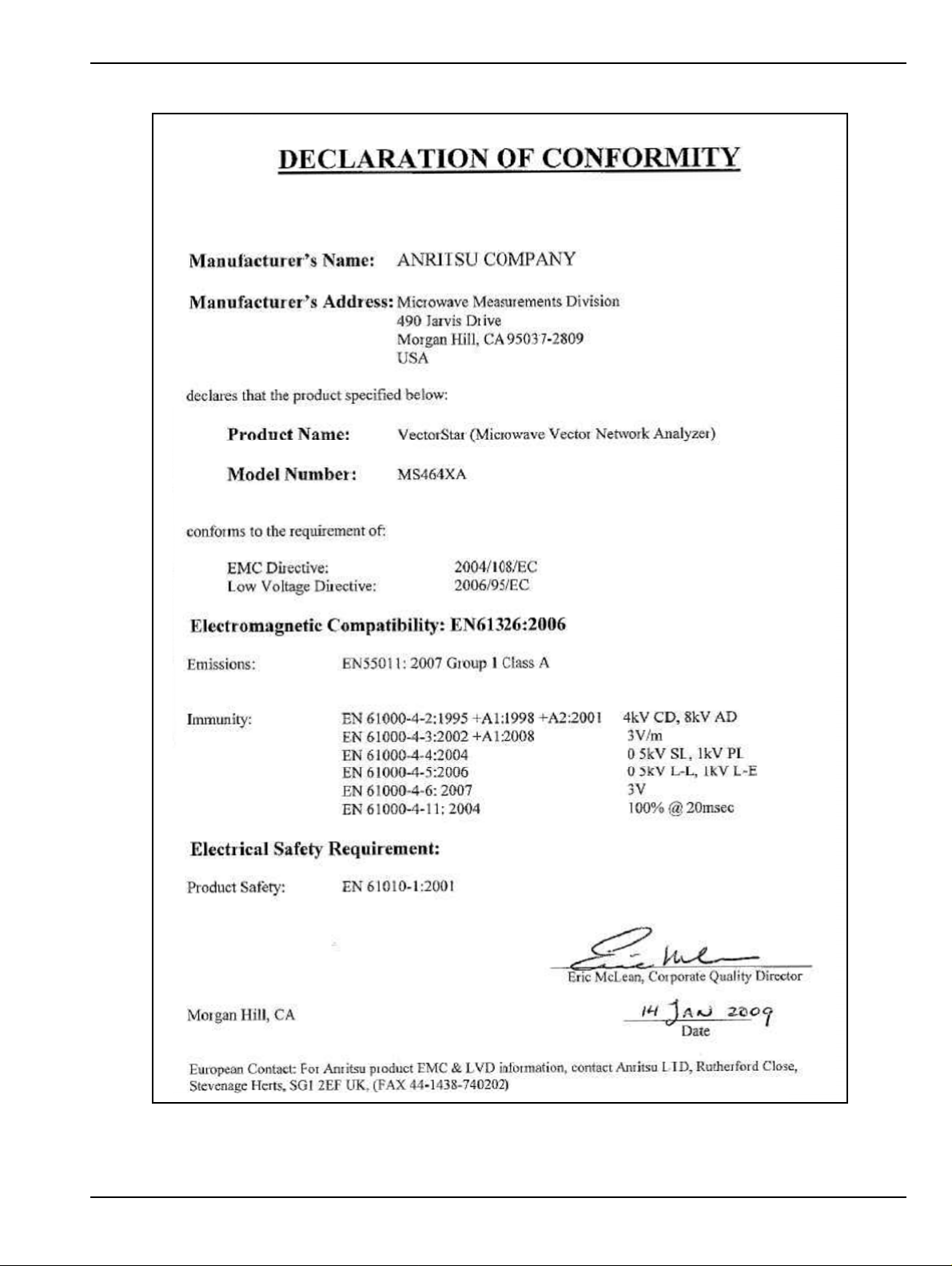
CE Conformity Marking
Anritsu affixes the CE Conformity marking onto its conforming products in accordance with Council Directives
of The Council Of The European Communities in order to indicat e that these products conform to the EMC and
LVD directive of the European Union (EU).
C-tick Conformity Marking
Anritsu affixes the C-tick marking onto its conforming products in accordance with the electromagnetic
compliance regulations of Australia and New Zealand in order to indicate that these products conform to the
EMC regulations of Australia and New Zealand.
Notes On Export Management
This product and its manuals may require an Export License or approval by the government of the product
country of origin for re-export from your country.
Before you export this product or any of its manuals, please contact Anritsu Company to confirm whether or
not these items are export-controlled.
When disposing of export-controlled items, the products and manuals need to be broken or shredded to such a
degree that they cannot be unlawfully used for military purposes.
Mercury Notification
This product uses an LCD backlight lamp that contains mercury. Disposal may be regulated due to
environmental considerations. Please contact your local authorities or, within the United States, the
Electronics Industries Alliance (www.eiae.org) for disposal or recycling information.
Perchlorate Notification
This product uses a small Lithium battery that may contain perchlorate installed internally on the circuit
board. Disposal may be regulated due to environmental considerations. Please contact your local authorities
for disposal or recycling information.
Title-6 PN: 10410-00266 Rev: L MS4640A Series VNA OM
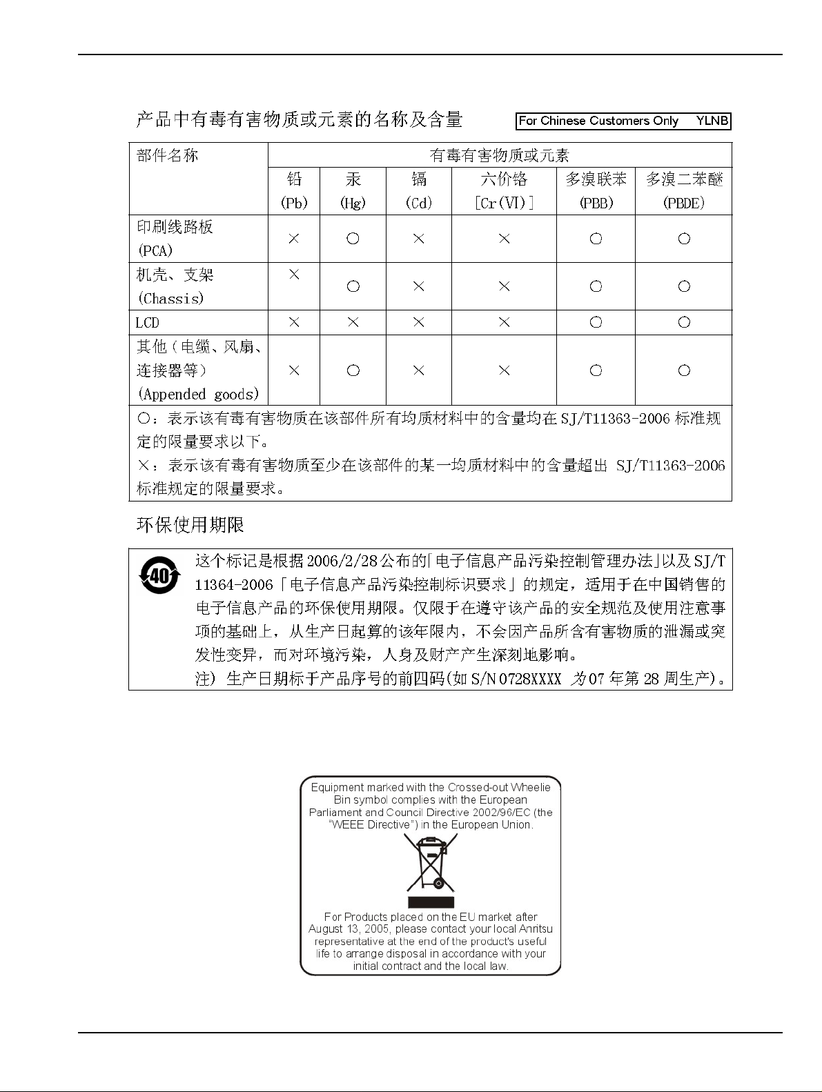
Chinese RoHS Statement
EPC WEEE Directive 2002/96/EC
MS4640A Series VNA OM PN: 10410-00266 Rev: L Title-7

Title-8 PN: 10410-00266 Rev: L MS4640A Series VNA OM
Safety Symbols
To prevent the risk of personal injury or loss related to equipment malfunction, Anritsu Company uses the
following symbols to indicate safety-related information. For your own safety, please read the information
carefully before operating the equipment.
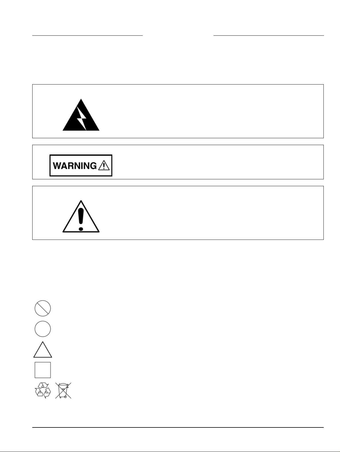
Symbols Used in Manuals
Danger
This indicates a very dangerous procedure that could result in serious
injury or death, and possible loss related to equipment malfunction, if not
performed properly.
Warning
Caution
This indicates a hazardous procedure that could result in light-to-severe
injury or loss related to equipment malfunction, if proper precautions are
not taken.
This indicates a hazardous procedure that could result in loss related to
equipment malfunction if proper precautions are not taken.
Safety Symbols Used on Equipment and in Manuals
The following safety symbols are used inside or on the equipment near operation locations to provide
information about safety items and operation precautions. Ensure that you clearly understand the meanings of
the symbols and take the necessary precautions before operating the equipment. Some or all of the following
five symbols may or may not be used on all Anritsu equipment. In addition, there may be other labels attached
to products that are not shown in the diagrams in this manual.
This indicates a prohibited operation. The prohibited operation is indicated symbolically in or near
the barred circle.
This indicates a compulsory safety precaution. The required operation is indicated symbolically in or
near the circle.
This indicates a warning or caution. The contents are indicated symbolically in or near the triangle.
This indicates a note. The contents are described in the box.
These indicate that the marked part should be recycled.
MS4640A Series VNA OM PN: 10410-00266 Rev: L Safety-1
For Safety
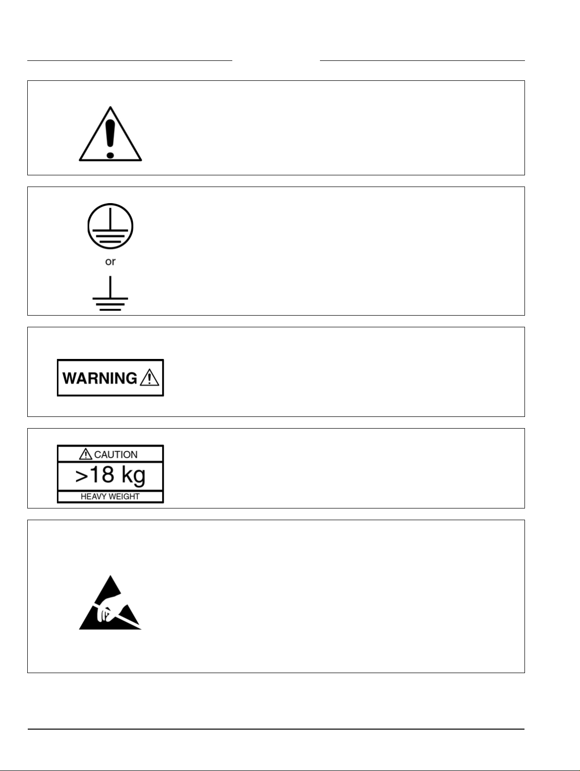
Warning
Warning
Warning
Always refer to the operation manual when working near locations at which
the alert mark, shown on the left, is attached. If the operation, etc., is
performed without heeding the advice in the operation manual, there is a
risk of personal injury. In addition, the equipment performance may be
reduced.
Moreover, this alert mark is sometimes used with other marks and
descriptions indicating other dangers.
When supplying power to this equipment, connect the accessory 3-pin
power cord to a 3-pin grounded power outlet. If power is supplied without
grounding the equipment, there is a risk of receiving a severe or fatal
electric shock.
This equipment can not be repaired by the operator. Do not attempt to
remove the equipment covers or to disassemble internal components.
Only qualified service technicians with a knowledge of electrical fire and
shock hazards should service this equipment. There are hig h-voltage p arts
in this equipment presenting a risk of severe injury or fatal electric shock to
untrained personnel. In addition, there is a risk of damage to precision
components.
Warning
Caution
Use two or more people to lift and move this equipment, or use an
equipment cart. There is a risk of back injury if this equipment is lifted by
one person.
Electrostatic Discharge (ESD) can damage the highly sensitive circuits in
the instrument. ESD is most likely to occur as test devices are being
connected to, or disconnected from, the instrument’s front and rear panel
ports and connectors. You can protect the instrument and test devices by
wearing a static-discharge wristband. Alternatively, you can ground
yourself to discharge any static charge by touching the outer chassis of the
grounded instrument before touching the instrume nt’s front and rear panel
ports and connectors. Avoid touching the test port center conductors
unless you are properly grounded and have eliminated the possibility of
static discharge.
Repair of damage that is found to be caused by electrostatic discharge is
not covered under warranty.
Safety-2 PN: 10410-00266 Rev: L MS4640A Series VNA OM

Chapter Descriptions
Chapter 1 — Overview
This chapter provides an overview of the VectorStar MS4640A Series Vector Network Analyzer (VNA)
and a description of its major functions and available documentation. A summary of available precision
component kits including AutoCal calibration kits, mechanical calibration kits, and verification kits is
included.
Chapter 2 — Installation
This chapter provides information for the initial inspection and preparation for use of the MS4640A Series
VNA and includes information on instrument installation, required operating environment, power
requirements, initial inspection, and optional rack mounting procedures. After power up, the various
power modes are described with general warm-up and calibration time intervals. The preventive
maintenance section includes information on cleaning and fuse replacement along with preparation for
storage or shipment. General set up procedures a re prov ided for remo te programming control over GPIB
and Ethernet or USB only networks.
Chapter 3 — Front and Rear Panels
The chapter provides an overview of the MS4640A Series VNA hardware user interface in clu din g fro nt
panel buttons, front panel connectors, and back panel connectors. Included are photographs of the front
and rear panels. Each front panel key is described with its function and a cross reference to the menu it
activates on the user interface display. Each port and connector is described with its connector type, its
function, input/output limits, and a cross-reference to a detailed connector pin-out diagram.
Chapter 4 — User Interface Display
The chapter describes the general display options of the MS4640A Series VNA and provides a general
description of the MENU BAR, the ICON TOOLBAR, and the right-side function menus. General
descriptions and procedures are provided for channel setup, trace graph setup, marker setup, and limit
line setup. The MS4640A Series VNA displays measurement data using a “Channel Concept” where each
channel can display both a different S-Parameter (or another specialt y para meter) and a di fferent graph
type. As each channel is selected, the previously selected trace graph types, scaling, reference delay, SParameter, and other parameters associated with that channel appear on the screen. In addition, the
same S-Parameter can be displayed simultaneously on two or more channels using the same or different
trace graph types.
Chapter 5 — Main Menu
This user interface (UI) reference chapter summary operational information about the UI and detailed
overview of the primary controls on the top-of-screen Menu Bar and Icon Bar, and the right-side application
Main Menu. The Main Menu is available for VectorStar VNAs. The Menu Bar provides drop-down menu
interface to major instrument functions. The Icon Bar provides single-click access many instrument
functions and is user-configurable to meet individual needs. The description of the Main Menu (MAIN)
provides top level descriptions of each major function with links to detailed descriptions of menus and
dialog boxes in subsequent chapters.
Appendix A — Vector Network Analyzer Primer
This chapter describes the basic functions of a Vector Network Analyzer (VNA) and how it measures
magnitude and phase characteristics of networks, amplifiers, attenuators, and antennas. Scattering
parameters (S-parameters) are defined.
Appendix B — Initial Checkout Procedures
The initial checkout procedure chapter describes the detailed procedures for initial operational checkout
(such as those performed by incoming quality inspectors) to ensure that the MS4640A Series VNA is full y
operational. A quick check procedure is described along with how to determine the instrument’s installed
options, current operating system, application software, and firmware versions. Other procedures
provided are self-test, non-ratio power, high-level signal, and system noise floor test.
MS4640A Series VNA OM PN: 10410-00266 Rev: L Contents-1

Chapter Descriptions (Continued}
Appendix C — Abbreviation Glossary
This glossary defines the abbreviations and terms that appear on the connectors, hard keys, menus, and
buttons of the MS4640A Series VNA. In some cases, due to space limitations, multiple abbreviations are
used for the same term or the same abbreviation is used with different punctuation.
Contents-2 PN: 10410-00266 Rev: L MS4640A Series VNA OM

Table of Contents
Chapter 1 — Overview
1-1 Introduction. . . . . . . . . . . . . . . . . . . . . . . . . . . . . . . . . . . . . . . . . . . . . . . . . . . . . . . . . . . . . . . . . . 1-1
1-2 VectorStar MS4640A Series VNA Description. . . . . . . . . . . . . . . . . . . . . . . . . . . . . . . . . . . . . . . 1-2
1-3 VectorStar MS4640A Series VNA Models . . . . . . . . . . . . . . . . . . . . . . . . . . . . . . . . . . . . . . . . . . 1-3
1-4 VectorStar VNA Options. . . . . . . . . . . . . . . . . . . . . . . . . . . . . . . . . . . . . . . . . . . . . . . . . . . . . . . . 1-4
Shipping Contents . . . . . . . . . . . . . . . . . . . . . . . . . . . . . . . . . . . . . . . . . . . . . . . . . . . . . . . . . . 1-6
1-5 VectorStar ME7838 Modular BB/mm-Wave VNA System . . . . . . . . . . . . . . . . . . . . . . . . . . . . . . 1-7
1-6 VectorStar ME7828A Standard BB/mm-Wave VNA System . . . . . . . . . . . . . . . . . . . . . . . . . . . . 1-9
Millimeter-Wave Module Options . . . . . . . . . . . . . . . . . . . . . . . . . . . . . . . . . . . . . . . . . . . . . . 1-10
1-7 VectorStar MN4690B Series Multiport VNA System . . . . . . . . . . . . . . . . . . . . . . . . . . . . . . . . . 1-11
1-8 VNA Instrument Control . . . . . . . . . . . . . . . . . . . . . . . . . . . . . . . . . . . . . . . . . . . . . . . . . . . . . . . 1-13
Graphical User Interface. . . . . . . . . . . . . . . . . . . . . . . . . . . . . . . . . . . . . . . . . . . . . . . . . . . . . 1-13
Front Panel Hard Keys . . . . . . . . . . . . . . . . . . . . . . . . . . . . . . . . . . . . . . . . . . . . . . . . . . . . . . 1-13
Hard Disk Configuration . . . . . . . . . . . . . . . . . . . . . . . . . . . . . . . . . . . . . . . . . . . . . . . . . . . . . 1-13
System Identification and Computer Name . . . . . . . . . . . . . . . . . . . . . . . . . . . . . . . . . . . . . . 1-13
Precision Component and Calibration Kits. . . . . . . . . . . . . . . . . . . . . . . . . . . . . . . . . . . . . . . 1-14
Automatic Calibrators . . . . . . . . . . . . . . . . . . . . . . . . . . . . . . . . . . . . . . . . . . . . . . . . . . . . . . . 1-14
1-9 Related Documentation . . . . . . . . . . . . . . . . . . . . . . . . . . . . . . . . . . . . . . . . . . . . . . . . . . . . . . . 1-15
VectorStar MS4640A Series Vector Network Analyzers . . . . . . . . . . . . . . . . . . . . . . . . . . . . 1-15
VectorStar ME7838 Series 2-Port BB/mmW VNA Measurement System . . . . . . . . . . . . . . . 1-15
VectorStar ME7828A Standard BB/mm Wave VNA Measurement System. . . . . . . . . . . . . . 1-15
VectorStar MN4690B Series Multiport VNA Measurement System . . . . . . . . . . . . . . . . . . . . 1-15
Calibration, Verification, and System Performance Verification. . . . . . . . . . . . . . . . . . . . . . . 1-16
Updates to Manuals . . . . . . . . . . . . . . . . . . . . . . . . . . . . . . . . . . . . . . . . . . . . . . . . . . . . . . . . 1-16
Documentation Conventions. . . . . . . . . . . . . . . . . . . . . . . . . . . . . . . . . . . . . . . . . . . . . . . . . . 1-16
1-10 Security Concerns for CPU Memory and the Hard Disk Drive . . . . . . . . . . . . . . . . . . . . . . . . . 1-17
Memory Overview. . . . . . . . . . . . . . . . . . . . . . . . . . . . . . . . . . . . . . . . . . . . . . . . . . . . . . . . . . 1-17
DRAM and Flash Memory . . . . . . . . . . . . . . . . . . . . . . . . . . . . . . . . . . . . . . . . . . . . . . . . . . . 1-17
Solid State Drive/Hard Disk Drive. . . . . . . . . . . . . . . . . . . . . . . . . . . . . . . . . . . . . . . . . . . . . . 1-17
1-11 Operating System. . . . . . . . . . . . . . . . . . . . . . . . . . . . . . . . . . . . . . . . . . . . . . . . . . . . . . . . . . . 1-18
Maintaining Operating System Integrity . . . . . . . . . . . . . . . . . . . . . . . . . . . . . . . . . . . . . . . . . 1-18
Antivirus Protection. . . . . . . . . . . . . . . . . . . . . . . . . . . . . . . . . . . . . . . . . . . . . . . . . . . . . . . . . 1-18
Windows Updates. . . . . . . . . . . . . . . . . . . . . . . . . . . . . . . . . . . . . . . . . . . . . . . . . . . . . . . . . . 1-18
Chapter 2 — Installation
2-1 Introduction. . . . . . . . . . . . . . . . . . . . . . . . . . . . . . . . . . . . . . . . . . . . . . . . . . . . . . . . . . . . . . . . . . 2-1
2-2 Unpacking the Product . . . . . . . . . . . . . . . . . . . . . . . . . . . . . . . . . . . . . . . . . . . . . . . . . . . . . . . . . 2-1
Initial Inspection . . . . . . . . . . . . . . . . . . . . . . . . . . . . . . . . . . . . . . . . . . . . . . . . . . . . . . . . . . . . 2-1
Preparation for Use. . . . . . . . . . . . . . . . . . . . . . . . . . . . . . . . . . . . . . . . . . . . . . . . . . . . . . . . . . 2-1
2-3 Optional Rack Mount Installation . . . . . . . . . . . . . . . . . . . . . . . . . . . . . . . . . . . . . . . . . . . . . . . . . 2-1
2-4 Installing and Configuring the Additional Solid State Drive. . . . . . . . . . . . . . . . . . . . . . . . . . . . . . 2-4
Procedure. . . . . . . . . . . . . . . . . . . . . . . . . . . . . . . . . . . . . . . . . . . . . . . . . . . . . . . . . . . . . . . . . 2-4
MS4640A Series VNA OM PN: 10410-00266 Rev: L Contents-3

Table of Contents (Continued}
2-5 Connecting External Devices . . . . . . . . . . . . . . . . . . . . . . . . . . . . . . . . . . . . . . . . . . . . . . . . . . . . 2-5
Connecting an External Mouse or Keyboard . . . . . . . . . . . . . . . . . . . . . . . . . . . . . . . . . . . . . . 2-5
Connecting an External XGA/VGA Monitor . . . . . . . . . . . . . . . . . . . . . . . . . . . . . . . . . . . . . . . 2-6
Connecting an External Printer. . . . . . . . . . . . . . . . . . . . . . . . . . . . . . . . . . . . . . . . . . . . . . . . . 2-7
Connecting Other USB Peripherals . . . . . . . . . . . . . . . . . . . . . . . . . . . . . . . . . . . . . . . . . . . . . 2-7
2-6 Operating Environment and Power Requirements. . . . . . . . . . . . . . . . . . . . . . . . . . . . . . . . . . . . 2-8
2-7 Power-On/Power-Off Procedures. . . . . . . . . . . . . . . . . . . . . . . . . . . . . . . . . . . . . . . . . . . . . . . . . 2-9
Procedure – Power-On to Standby Mode. . . . . . . . . . . . . . . . . . . . . . . . . . . . . . . . . . . . . . . . 2-10
Procedure – Standby Mode to Operate Mode . . . . . . . . . . . . . . . . . . . . . . . . . . . . . . . . . . . . 2-10
Procedure – Operate Mode to Standby Mode . . . . . . . . . . . . . . . . . . . . . . . . . . . . . . . . . . . . 2-11
Procedure – Standby Mode to Power-Off. . . . . . . . . . . . . . . . . . . . . . . . . . . . . . . . . . . . . . . . 2-11
2-8 GPIB Setup. . . . . . . . . . . . . . . . . . . . . . . . . . . . . . . . . . . . . . . . . . . . . . . . . . . . . . . . . . . . . . . . . 2-12
Configuring the Dedicated GPIB Port. . . . . . . . . . . . . . . . . . . . . . . . . . . . . . . . . . . . . . . . . . . 2-12
Configuring the IEEE 488.2 GPIB Port. . . . . . . . . . . . . . . . . . . . . . . . . . . . . . . . . . . . . . . . . . 2-16
Configuring the VectorStar VNA GPIB Address . . . . . . . . . . . . . . . . . . . . . . . . . . . . . . . . . . . 2-17
2-9 Ethernet LAN TCP/IP and USB Setup . . . . . . . . . . . . . . . . . . . . . . . . . . . . . . . . . . . . . . . . . . . . 2-18
Default Plug-and-Play Configuration. . . . . . . . . . . . . . . . . . . . . . . . . . . . . . . . . . . . . . . . . . . . 2-18
Manually Configuring TCP/IP Ethernet LAN Settings. . . . . . . . . . . . . . . . . . . . . . . . . . . . . . . 2-19
2-10 Configuring the Remote Language. . . . . . . . . . . . . . . . . . . . . . . . . . . . . . . . . . . . . . . . . . . . . . 2-22
2-11 Calibration/Verification Interval. . . . . . . . . . . . . . . . . . . . . . . . . . . . . . . . . . . . . . . . . . . . . . . . . 2-23
2-12 Fuse Maintenance . . . . . . . . . . . . . . . . . . . . . . . . . . . . . . . . . . . . . . . . . . . . . . . . . . . . . . . . . . 2-23
Fuse Summary . . . . . . . . . . . . . . . . . . . . . . . . . . . . . . . . . . . . . . . . . . . . . . . . . . . . . . . . . . . . 2-23
External Rear Panel AC Input Fuses . . . . . . . . . . . . . . . . . . . . . . . . . . . . . . . . . . . . . . . . . . . 2-23
Bias Fuse Replacement . . . . . . . . . . . . . . . . . . . . . . . . . . . . . . . . . . . . . . . . . . . . . . . . . . . . . 2-24
2-13 Operating System Restore . . . . . . . . . . . . . . . . . . . . . . . . . . . . . . . . . . . . . . . . . . . . . . . . . . . . 2-25
Procedure . . . . . . . . . . . . . . . . . . . . . . . . . . . . . . . . . . . . . . . . . . . . . . . . . . . . . . . . . . . . . . . . 2-25
2-14 Preparation for Storage or Shipment . . . . . . . . . . . . . . . . . . . . . . . . . . . . . . . . . . . . . . . . . . . . 2-26
Preparation for Storage. . . . . . . . . . . . . . . . . . . . . . . . . . . . . . . . . . . . . . . . . . . . . . . . . . . . . . 2-26
Preparation for Shipment . . . . . . . . . . . . . . . . . . . . . . . . . . . . . . . . . . . . . . . . . . . . . . . . . . . . 2-26
Chapter 3 — Front and Rear Panels
3-1 Chapter Overview. . . . . . . . . . . . . . . . . . . . . . . . . . . . . . . . . . . . . . . . . . . . . . . . . . . . . . . . . . . . . 3-1
3-2 Front Panel Touch Screen . . . . . . . . . . . . . . . . . . . . . . . . . . . . . . . . . . . . . . . . . . . . . . . . . . . . . . 3-1
3-3 Front Panel Hard Keys and Connectors. . . . . . . . . . . . . . . . . . . . . . . . . . . . . . . . . . . . . . . . . . . . 3-2
Front Panel Hard Key and Connector Description . . . . . . . . . . . . . . . . . . . . . . . . . . . . . . . . . . 3-4
3-4 Rear Panel Ports and Connectors . . . . . . . . . . . . . . . . . . . . . . . . . . . . . . . . . . . . . . . . . . . . . . . 3- 12
Rear Panel Port and Connector Descriptions. . . . . . . . . . . . . . . . . . . . . . . . . . . . . . . . . . . . . 3-14
Chapter 4 — User Interface Display
4-1 Chapter Overview. . . . . . . . . . . . . . . . . . . . . . . . . . . . . . . . . . . . . . . . . . . . . . . . . . . . . . . . . . . . . 4-1
4-2 User Interface Main Screen . . . . . . . . . . . . . . . . . . . . . . . . . . . . . . . . . . . . . . . . . . . . . . . . . . . . . 4-1
Single Channel User Interface Control and Display Areas. . . . . . . . . . . . . . . . . . . . . . . . . . . . 4-2
Multiple Channel User Interface Control and Display Areas. . . . . . . . . . . . . . . . . . . . . . . . . . . 4-3
Function Access . . . . . . . . . . . . . . . . . . . . . . . . . . . . . . . . . . . . . . . . . . . . . . . . . . . . . . . . . . . . 4-6
4-3 Using the Front Panel Keys . . . . . . . . . . . . . . . . . . . . . . . . . . . . . . . . . . . . . . . . . . . . . . . . . . . . . 4-8
Contents-4 PN: 10410-00266 Rev: L MS4640A Series VNA OM

Table of Contents (Continued}
4-4 Using the Menu Bar Interface. . . . . . . . . . . . . . . . . . . . . . . . . . . . . . . . . . . . . . . . . . . . . . . . . . . . 4-9
Menu Bar Overview . . . . . . . . . . . . . . . . . . . . . . . . . . . . . . . . . . . . . . . . . . . . . . . . . . . . . . . . . 4-9
Menu Bar General Operation . . . . . . . . . . . . . . . . . . . . . . . . . . . . . . . . . . . . . . . . . . . . . . . . . 4-10
Menu Bar Drop-Down Menus and Commands. . . . . . . . . . . . . . . . . . . . . . . . . . . . . . . . . . . . 4-10
4-5 Icon Toolbar . . . . . . . . . . . . . . . . . . . . . . . . . . . . . . . . . . . . . . . . . . . . . . . . . . . . . . . . . . . . . . . . 4-22
Overview. . . . . . . . . . . . . . . . . . . . . . . . . . . . . . . . . . . . . . . . . . . . . . . . . . . . . . . . . . . . . . . . . 4-22
Using the Icon Toolbar Interface. . . . . . . . . . . . . . . . . . . . . . . . . . . . . . . . . . . . . . . . . . . . . . . 4-22
Available Icon Functions. . . . . . . . . . . . . . . . . . . . . . . . . . . . . . . . . . . . . . . . . . . . . . . . . . . . . 4-22
4-6 MAIN Menu and Application Menus . . . . . . . . . . . . . . . . . . . . . . . . . . . . . . . . . . . . . . . . . . . . . . 4-29
4-7 Using the Main Menu Interface. . . . . . . . . . . . . . . . . . . . . . . . . . . . . . . . . . . . . . . . . . . . . . . . . . 4-31
Types of Menus, Menu Buttons, and Menu Toolbars. . . . . . . . . . . . . . . . . . . . . . . . . . . . . . . 4-31
Menu Title. . . . . . . . . . . . . . . . . . . . . . . . . . . . . . . . . . . . . . . . . . . . . . . . . . . . . . . . . . . . . . . . 4-32
Menu Buttons . . . . . . . . . . . . . . . . . . . . . . . . . . . . . . . . . . . . . . . . . . . . . . . . . . . . . . . . . . . . . 4-32
Menu Navigation Buttons . . . . . . . . . . . . . . . . . . . . . . . . . . . . . . . . . . . . . . . . . . . . . . . . . . . . 4-32
Back Button . . . . . . . . . . . . . . . . . . . . . . . . . . . . . . . . . . . . . . . . . . . . . . . . . . . . . . . . . . . . . . 4-32
Next Button. . . . . . . . . . . . . . . . . . . . . . . . . . . . . . . . . . . . . . . . . . . . . . . . . . . . . . . . . . . . . . . 4-32
Home Button. . . . . . . . . . . . . . . . . . . . . . . . . . . . . . . . . . . . . . . . . . . . . . . . . . . . . . . . . . . . . . 4-32
Menu Buttons . . . . . . . . . . . . . . . . . . . . . . . . . . . . . . . . . . . . . . . . . . . . . . . . . . . . . . . . . . . . . 4-32
Display Button. . . . . . . . . . . . . . . . . . . . . . . . . . . . . . . . . . . . . . . . . . . . . . . . . . . . . . . . . . . . . 4-32
Plain Buttons . . . . . . . . . . . . . . . . . . . . . . . . . . . . . . . . . . . . . . . . . . . . . . . . . . . . . . . . . . . . . 4-33
Toggle Buttons . . . . . . . . . . . . . . . . . . . . . . . . . . . . . . . . . . . . . . . . . . . . . . . . . . . . . . . . . . . . 4-33
Field Selection Buttons. . . . . . . . . . . . . . . . . . . . . . . . . . . . . . . . . . . . . . . . . . . . . . . . . . . . . . 4-33
Field Toolbars. . . . . . . . . . . . . . . . . . . . . . . . . . . . . . . . . . . . . . . . . . . . . . . . . . . . . . . . . . . . . 4-34
Button Selection Icon . . . . . . . . . . . . . . . . . . . . . . . . . . . . . . . . . . . . . . . . . . . . . . . . . . . . . . . 4-34
Button Selection Groups. . . . . . . . . . . . . . . . . . . . . . . . . . . . . . . . . . . . . . . . . . . . . . . . . . . . . 4-35
Auto-Return Button Groups . . . . . . . . . . . . . . . . . . . . . . . . . . . . . . . . . . . . . . . . . . . . . . . . . . 4-36
Completion Checkmark Button. . . . . . . . . . . . . . . . . . . . . . . . . . . . . . . . . . . . . . . . . . . . . . . . 4-37
4-8 Using Dialog Boxes . . . . . . . . . . . . . . . . . . . . . . . . . . . . . . . . . . . . . . . . . . . . . . . . . . . . . . . . . . 4-37
Standard Dialog Box Buttons . . . . . . . . . . . . . . . . . . . . . . . . . . . . . . . . . . . . . . . . . . . . . . . . . 4-37
4-9 Setting the Main Display as Resizeable and/or Task Bar. . . . . . . . . . . . . . . . . . . . . . . . . . . . . . 4-38
Procedure. . . . . . . . . . . . . . . . . . . . . . . . . . . . . . . . . . . . . . . . . . . . . . . . . . . . . . . . . . . . . . . . 4-39
4-10 Instrument Status Display Area . . . . . . . . . . . . . . . . . . . . . . . . . . . . . . . . . . . . . . . . . . . . . . . . 4-40
Instrument Status Messages . . . . . . . . . . . . . . . . . . . . . . . . . . . . . . . . . . . . . . . . . . . . . . . . . 4-41
4-11 Channel Status Display Area . . . . . . . . . . . . . . . . . . . . . . . . . . . . . . . . . . . . . . . . . . . . . . . . . . 4-42
4-12 Working with the Number of Points . . . . . . . . . . . . . . . . . . . . . . . . . . . . . . . . . . . . . . . . . . . . . 4-43
Maximum Points Set to 25,000. . . . . . . . . . . . . . . . . . . . . . . . . . . . . . . . . . . . . . . . . . . . . . . . 4-43
Maximum Points Set to 100,000. . . . . . . . . . . . . . . . . . . . . . . . . . . . . . . . . . . . . . . . . . . . . . . 4-43
To Change the Number of Points. . . . . . . . . . . . . . . . . . . . . . . . . . . . . . . . . . . . . . . . . . . . . . 4-43
4-13 Working with Channels. . . . . . . . . . . . . . . . . . . . . . . . . . . . . . . . . . . . . . . . . . . . . . . . . . . . . . . 4-44
25,000 Point Mode . . . . . . . . . . . . . . . . . . . . . . . . . . . . . . . . . . . . . . . . . . . . . . . . . . . . . . . . . 4-44
100,000 Point Mode . . . . . . . . . . . . . . . . . . . . . . . . . . . . . . . . . . . . . . . . . . . . . . . . . . . . . . . . 4-44
MS4640A Series VNA OM PN: 10410-00266 Rev: L Contents-5

Table of Contents (Continued}
4-14 Working with Traces . . . . . . . . . . . . . . . . . . . . . . . . . . . . . . . . . . . . . . . . . . . . . . . . . . . . . . . . . 4-44
Types of Trace Displays . . . . . . . . . . . . . . . . . . . . . . . . . . . . . . . . . . . . . . . . . . . . . . . . . . . . . 4-44
Trace Data Types . . . . . . . . . . . . . . . . . . . . . . . . . . . . . . . . . . . . . . . . . . . . . . . . . . . . . . . . . . 4-44
Trace Display Graphs. . . . . . . . . . . . . . . . . . . . . . . . . . . . . . . . . . . . . . . . . . . . . . . . . . . . . . . 4-45
Trace Labels. . . . . . . . . . . . . . . . . . . . . . . . . . . . . . . . . . . . . . . . . . . . . . . . . . . . . . . . . . . . . . 4-47
Trace Label Abbreviations . . . . . . . . . . . . . . . . . . . . . . . . . . . . . . . . . . . . . . . . . . . . . . . . . . . 4-48
Rectilinear Single Graph. . . . . . . . . . . . . . . . . . . . . . . . . . . . . . . . . . . . . . . . . . . . . . . . . . . . . 4-50
Rectilinear Paired Graphs. . . . . . . . . . . . . . . . . . . . . . . . . . . . . . . . . . . . . . . . . . . . . . . . . . . . 4-52
Smith Charts. . . . . . . . . . . . . . . . . . . . . . . . . . . . . . . . . . . . . . . . . . . . . . . . . . . . . . . . . . . . . . 4-53
Smith Chart with Impedance (Circuit Resistance and Reactance). . . . . . . . . . . . . . . . . . . . . 4-53
Smith Chart with Admittance (Conductance and Susceptance). . . . . . . . . . . . . . . . . . . . . . . 4-54
Polar Graphs. . . . . . . . . . . . . . . . . . . . . . . . . . . . . . . . . . . . . . . . . . . . . . . . . . . . . . . . . . . . . . 4-56
Group Delay Graphs. . . . . . . . . . . . . . . . . . . . . . . . . . . . . . . . . . . . . . . . . . . . . . . . . . . . . . . . 4-56
Power Graphs. . . . . . . . . . . . . . . . . . . . . . . . . . . . . . . . . . . . . . . . . . . . . . . . . . . . . . . . . . . . . 4-58
4-15 Working with Reference Lines and Reference Position . . . . . . . . . . . . . . . . . . . . . . . . . . . . . . 4-59
4-16 Working with Limit Lines. . . . . . . . . . . . . . . . . . . . . . . . . . . . . . . . . . . . . . . . . . . . . . . . . . . . . . 4-60
4-17 Working with Frequency Blanking. . . . . . . . . . . . . . . . . . . . . . . . . . . . . . . . . . . . . . . . . . . . . . . 4-61
Chapter 5 — Main Menu
5-1 Chapter Overview. . . . . . . . . . . . . . . . . . . . . . . . . . . . . . . . . . . . . . . . . . . . . . . . . . . . . . . . . . . . . 5-1
5-2 MAIN Menu. . . . . . . . . . . . . . . . . . . . . . . . . . . . . . . . . . . . . . . . . . . . . . . . . . . . . . . . . . . . . . . . . . 5-1
Appendix A — Vector Network Analyzer Primer
A-1 Appendix Overview. . . . . . . . . . . . . . . . . . . . . . . . . . . . . . . . . . . . . . . . . . . . . . . . . . . . . . . . . . . . A-1
A-2 General Description . . . . . . . . . . . . . . . . . . . . . . . . . . . . . . . . . . . . . . . . . . . . . . . . . . . . . . . . . . . A-1
A-3 Instrument Description . . . . . . . . . . . . . . . . . . . . . . . . . . . . . . . . . . . . . . . . . . . . . . . . . . . . . . . . . A-2
Source Module . . . . . . . . . . . . . . . . . . . . . . . . . . . . . . . . . . . . . . . . . . . . . . . . . . . . . . . . . . . . . A-2
Test Set Module . . . . . . . . . . . . . . . . . . . . . . . . . . . . . . . . . . . . . . . . . . . . . . . . . . . . . . . . . . . . A-2
Analyzer Module. . . . . . . . . . . . . . . . . . . . . . . . . . . . . . . . . . . . . . . . . . . . . . . . . . . . . . . . . . . . A-2
A-4 Network Analyzers . . . . . . . . . . . . . . . . . . . . . . . . . . . . . . . . . . . . . . . . . . . . . . . . . . . . . . . . . . . . A-3
Scalar Analyzer Comparison . . . . . . . . . . . . . . . . . . . . . . . . . . . . . . . . . . . . . . . . . . . . . . . . . . A-3
Vector Network Analyzer Basics. . . . . . . . . . . . . . . . . . . . . . . . . . . . . . . . . . . . . . . . . . . . . . . . A-4
A-5 Polar Display . . . . . . . . . . . . . . . . . . . . . . . . . . . . . . . . . . . . . . . . . . . . . . . . . . . . . . . . . . . . . . . A-13
Resistive and Reactive Terms . . . . . . . . . . . . . . . . . . . . . . . . . . . . . . . . . . . . . . . . . . . . . . . . A-13
A-6 Smith Chart. . . . . . . . . . . . . . . . . . . . . . . . . . . . . . . . . . . . . . . . . . . . . . . . . . . . . . . . . . . . . . . . . A-14
Measurement Error Correction . . . . . . . . . . . . . . . . . . . . . . . . . . . . . . . . . . . . . . . . . . . . . . . . A-14
Appendix B — Initial Checkout Procedures
B-1 Introduction. . . . . . . . . . . . . . . . . . . . . . . . . . . . . . . . . . . . . . . . . . . . . . . . . . . . . . . . . . . . . . . . . . B-1
B-2 Checkout Introduction. . . . . . . . . . . . . . . . . . . . . . . . . . . . . . . . . . . . . . . . . . . . . . . . . . . . . . . . . . B-1
B-3 Required Equipment. . . . . . . . . . . . . . . . . . . . . . . . . . . . . . . . . . . . . . . . . . . . . . . . . . . . . . . . . . . B-1
B-4 Self Test Procedure . . . . . . . . . . . . . . . . . . . . . . . . . . . . . . . . . . . . . . . . . . . . . . . . . . . . . . . . . . . B-1
Overview. . . . . . . . . . . . . . . . . . . . . . . . . . . . . . . . . . . . . . . . . . . . . . . . . . . . . . . . . . . . . . . . . . B-1
Procedure . . . . . . . . . . . . . . . . . . . . . . . . . . . . . . . . . . . . . . . . . . . . . . . . . . . . . . . . . . . . . . . . . B-2
Contents-6 PN: 10410-00266 Rev: L MS4640A Series VNA OM

Table of Contents (Continued}
B-5 Non-Ratio Power Procedure . . . . . . . . . . . . . . . . . . . . . . . . . . . . . . . . . . . . . . . . . . . . . . . . . . . . B-4
Overview. . . . . . . . . . . . . . . . . . . . . . . . . . . . . . . . . . . . . . . . . . . . . . . . . . . . . . . . . . . . . . . . . . B-4
Procedure. . . . . . . . . . . . . . . . . . . . . . . . . . . . . . . . . . . . . . . . . . . . . . . . . . . . . . . . . . . . . . . . . B-4
B-6 High Level Noise Test . . . . . . . . . . . . . . . . . . . . . . . . . . . . . . . . . . . . . . . . . . . . . . . . . . . . . . . . . B-8
Overview. . . . . . . . . . . . . . . . . . . . . . . . . . . . . . . . . . . . . . . . . . . . . . . . . . . . . . . . . . . . . . . . . . B-8
Procedure. . . . . . . . . . . . . . . . . . . . . . . . . . . . . . . . . . . . . . . . . . . . . . . . . . . . . . . . . . . . . . . . . B-8
B-7 System Noise Floor Test . . . . . . . . . . . . . . . . . . . . . . . . . . . . . . . . . . . . . . . . . . . . . . . . . . . . . . B-12
Overview. . . . . . . . . . . . . . . . . . . . . . . . . . . . . . . . . . . . . . . . . . . . . . . . . . . . . . . . . . . . . . . . . B-12
Procedure. . . . . . . . . . . . . . . . . . . . . . . . . . . . . . . . . . . . . . . . . . . . . . . . . . . . . . . . . . . . . . . . B-12
Appendix C — Abbreviation Glossary
C-1 Appendix Overview . . . . . . . . . . . . . . . . . . . . . . . . . . . . . . . . . . . . . . . . . . . . . . . . . . . . . . . . . . . C-1
C-2 Glossary. . . . . . . . . . . . . . . . . . . . . . . . . . . . . . . . . . . . . . . . . . . . . . . . . . . . . . . . . . . . . . . . . . . . C-1
Subject Index
MS4640A Series VNA OM PN: 10410-00266 Rev: L Contents-7

Table of Contents (Continued}
Contents-8 PN: 10410-00266 Rev: L MS4640A Series VNA OM

Chapter 1 — Overview
1-1 Introduction
This chapter provides an overview of the VectorStar MS4640A Series Vector Network Analyzer (VNA) and a
description of its major functions and available documentation. A summary of available precision component
kits including AutoCal calibration kits, mechani c al calibration kits, and verification kits is included.
MS4640A Series VNA OM PN: 10410-00266 Rev: L 1-1
1-2 VectorStar MS4640A Series VNA Description Overview
1-2 VectorStar MS4640A Series VNA Description
The MS4640A Series VNA is an instrument system that contains a built-in source, test set, and analyzer. Test
results are displayed real time on a front panel touch screen or also to a separate video monitor. Screen
captures can easily be printed or saved in common graphic file formats.
Depending on the model and installed options, the MS4640A Series VNAs provide a maximum frequency range
from 70 kHz to 70 GHz for standalone VNAs. Through its front panel user interface, the instrument can be
quickly configured to provide either:
• 25,000 Points
MS4640A Series VNAs have up to 25,000 total test points available, with up to 16 channels, and each
channel with up to 16 trace display graphs where each channel is configured as a virtual separate VNA.
Each trace can have up to 12 standard markers and one reference marker.
• 100,000 Points
The VNA can be configured with up to 100,000 total test points, limited to one channel with up to 16
trace display graphs. Each trace can have up to 12 standard markers and one reference marker.
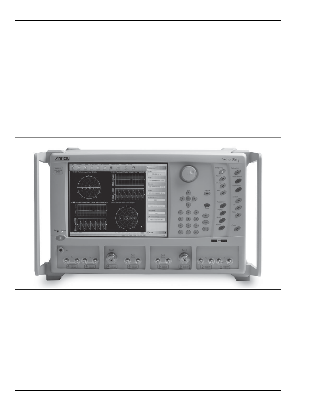
Figure 1-1. VectorStar MS4647A VNA Front Panel - Equipped with Option 051
1-2 PN: 10410-00266 Rev: L MS4640A Series VNA OM

Overview 1-3 VectorStar MS4640A Series VNA Models
1-3 VectorStar MS4640A Series VNA Models
The VectorStar VNA is available in four basic models as shown in Table 1-1.
Table 1-1. VectorStar MS4640A Series VNA Models
VNA Model
Number Name Specifications Test Port Connectors
MS4642A Microwave Vector Network Ana lyzer 10 MHz to 20 GHz K (m) Connector Test Ports
MS4644A Microwave Vector Network Ana lyzer 10 MHz to 40 GHz K (m) Connector Test Ports
MS4645A Microwave Vector Network Ana lyzer 10 MHz to 50 GHz V (m) Connector Test Ports
MS4647A Microwave Vector Network Ana lyzer 10 MHz to 70 GHz V (m) Connector Test Ports
For additional technical specifications and configuratio n data, see:
• VectorStar MS4640A Series VNA Technical Data Sheet and Configuration Guide – 11410-00432
MS4640A Series VNA OM PN: 10410-00266 Rev: L 1-3

1-4 VectorStar VNA Options Overview
1-4 VectorStar VNA Options
The available options depend on the VNA instrument model number as shown in Table 1-2 below.
Table 1-2. VectorStar MS4640A Series VNA Options (1 of 2)
Option
Number Option Name and Features VNA Model and Option Compatibility
Option 001 Rack Mount Option
• Adds 19” Rack Mounting Handles
Option 002 Time Domain Option
• Displays all S-parameters and
overlays with Frequency Domain,
Low-pass Mode with added
harmonics frequency list flexibility,
Band-pass Mode, Phasor Impulse
Mode, Windowing, Gating (passband or reject-band), and Frequency
with Time Gate.
Option 004 Additional Solid State Drive (SSD)
• Plug and play Serial ATA SSD
equipped with O/S and VectorStar
Application.
• Recommended for security
operations.
Option 007 Receiver Offset
• Provides Multiple Source, which
includes mixer, IMD, and other
measurements where the source and
receiver operate at different
frequencies.
• Independent Source/Receive
Functions: Allows independent
source and receive functions for
Mixer, Harmonics, IMD, and other
measurements, where the source
and receive frequencies are offset.
• Multiple Source Control Mode:
Provides independent control the
frequencies of up to four external
sources, in addition to the internal
source, and the receiver, in a
synchronized manner.
• NxN Frequency-Translated Devices:
Provides calibration and
measurements capability for NxN
Frequency-translated devices.
• For accurate and absolute magnitude
and phase measurements of match,
gain/loss, and group delay of devices
such as mixers and converters.
Option 041 Noise Figure Can be equipped on all MS4640A VNAs.
All MS4640A VNAs MS4640A-001
All MS4640A VNAs MS4640A-002
All MS4640A VNAs MS4640A-004
All MS4640A VNAs
Option 007 is required for:
• Option 080/081 – Broadband/
Millimeter-Wave Measurement
Capability (MS4647A VNAs only)
• Option 082/083 – Millimeter-Wave
Measurement Capability (All MS4640A
VNAs)
• Requires front/rear panel access loop s
provided by Option 051, 061, or 062.
Order
Number
MS4640A-007
MS4640A-041
1-4 PN: 10410-00266 Rev: L MS4640A Series VNA OM

Overview 1-4 VectorStar VNA Options
Table 1-2. VectorStar MS4640A Series VNA Options (2 of 2)
Option
Number Option Name and Features VNA Model and Option Compatibility
Option 051 Direct Access Loops Can be equipped on all MS4640A VNAs.
Order
Number
MS464xA-051
• Not compatible with Option 061 or
Option 062 Active Measurement Suite
(below) which also include loops.
Option 061 Active Measurements Suite with
2 Attenuators
Can be equipped on all MS4640A VNAs.
• Not compatible with Option 051 Loops
MS464xA-061
(above) or Option 062 Active
Measurement Suite Four Attenuators
(below).
Option 062 Active Measurements Suite with
4 Attenuators
Can be equipped on all MS4640A VNAs.
• Not compatible with Option 051 Loops
MS464xA-062
(above) or Option 061 Active
Measurement Suite Two Attenuators
(above).
Option 070 70 kHz Low-End Frequency Extension
Can be equipped on all MS4640A VNAs. MS464xA-070
• Defines the VNA instrument low-side
frequency limit.
• Provides a lower limit specified to
70 kHz but which is allowed to go to
40 kHz.
Option 080 Modular Broadband/Millimeter-Wave
Connection Capability
• Does not include Test Set, external
cables, or Millimeter-Wave Modules.
For MS4647A VNAs only.
• Use Option 080 if the VNA is not
equipped with Option 051, 061, or 062
(above).
MS4647A-080
• Not compatible with Option 081
(below).
Option 081 Modular Broadband/Millimeter-Wave
Connection Capability
• Does not include Test Set, external
cables, or Millimeter-Wave Modules.
For MS4647A VNAs only.
• Use Option 081 if the VNA is not
equipped with Option 051, 061, or 062
(above).
MS4647A-081
• Not compatible with Option 080
(above).
Option 082 Millimeter-Wave Capability
• Does not include Test Set, external
cables, or Millimeter-Wave modules.
Can be equipped on all MS4640A VNAs.
• Use Option 082 if the VNA is not
equipped with Option 051, 061, or 062
MS464xA-082
(above).
• Not compatible with Option 083
(below).
Option 083 Millimeter-Wave Capability
• Does not include Test Set, external
cables, or Millimeter-Wave modules.
Can be equipped on all MS4640A VNAs.
• Use Option 081 if the VNA is equipped
with Option 051, 061, or 062 (above).
MS464xA-083
• Not compatible with Option 082
(above).
– VNA Hard Shell Transit Case All MS4640A VNAs 760-246
– Extended Warranty and Service
All MS4640A VNAs MS464xA-ESxxx
Options
Option 098 Standard Calibration All MS4640A VNAs MS464xA-098
Option 099 Premium Calibration with Certification All MS4640A VNAs MS464xA-099
MS4640A Series VNA OM PN: 10410-00266 Rev: L 1-5
1-4 VectorStar VNA Options Overview
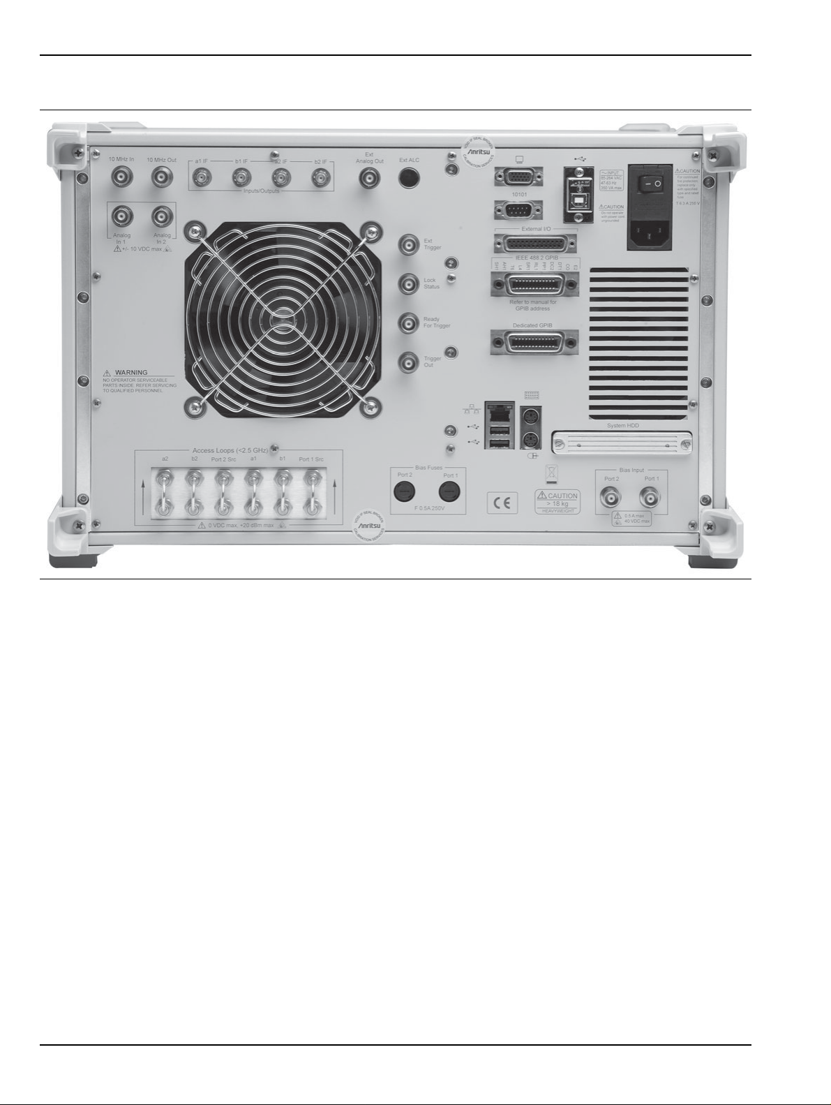
Figure 1-2. VectorStar MS4647 VNA Rear Panel - Equipped with Option 051
Shipping Contents
Each instrument includes the following:
• CD with technical publications and manuals in PDF format and miscellaneous software utilities
• DVD with a back-up image of the instrument’s solid state drive
• USB optical mouse
• Power cord
1-6 PN: 10410-00266 Rev: L MS4640A Series VNA OM

Overview 1-5 VectorStar ME7838 Modular BB/mm-Wave VNA System
1-5 VectorStar ME7838 Modular BB/mm-Wave VNA System
The modular broadband/millimeter-wave (BB/mm-Wave) system is available in two basic configurations.
Additional configuration and configuration information is available in the relevant technical data sheet.
Table 1-3. VectorStar ME7838 Series Modular Broadband/Millimeter-Wave VNA System (1 of 2)
Part Number Name Specifications
Standard ME7838 Configuration Components
MS4647A VectorStar MS4647A Vector Network Analyzer
(VNA)
MS4640A-007 Receiver Offset Option
MS4640A-002 Time Domain Option
MS4640A-070 70 kHz Low End Frequency Extension
MS4640A-08X Broadband System Select one:
3739A Broadband/Millimeter-Wave Test Set With front and rear panel interface cables
3739C Broadband/Millimeter-Wave Test Set
(Required for use with MA25300A 145 GHz
Broadband modules)
3743A Millimeter-Wave Module 70 GHz to 110+ GHz
MA25300A Millimeter-Wave Module 54 GHz to 145 GHz
ME7838A-SS020 On Site System Assembly and Verification
Phase Stable Cable Option – Select One (1)
10 MHz to 70 GHz
V (m) Connector Test Ports
• Use MS4647A-080 if VNA Option 051,
061, or 062 is NOT selected below.
• Use MS4647A-081 if VNA Option 051,
061, or 062 IS selected below.
With front and rear panel interface cables
• 2 each with mounting bracket
• 2 each with mounting bracket
806-206 1.85 mm Phase St able Interconnect Cable 70 cm (24 inches)
• V (m) to V (f)
•2 cables
806-209 1.85 mm Phase St able Interconnect Cable 91 cm (36 inches)
• V (m) to V (f)
•2 cables
MS4647A VNA Front Panel Options – Select None or One (1)
MS4647A-051 Front Panel Loops Six (6) Front Panel Loops
• Provides front panel loops for b 1, a1, Por t
1 Source, Port 2 Source, a2, and b2
• If Option 051 is selected, use Option
MS4647A-081 above.
MS4647A-061 Active Measurement Suite, 2 Attenuators Two (2) Attenuators
• Include the six (6) front panel loops above.
• Two (2) Attenuators
• Bias tees in test set
• Gain compression
• Efficiency measurement software
• If Option 061 is selected, use Option
MS4647A-081 above.
MS4640A Series VNA OM PN: 10410-00266 Rev: L 1-7

1-5 VectorStar ME7838 Modular BB/mm-Wave VNA System Overview
Table 1-3. VectorStar ME7838 Series Modular Broadband/Millimeter-Wave VNA System (2 of 2)
Part Number Name Specifications
MS4647A-062 Active Measurement Suite, 4 Attenuators Four (4) Attenuators
• Include the six (6) front panel loops above.
• Four (4) Attenuators
• Bias tees in test set
• Gain compression
• Efficiency measurement software
• If Option 062 is selected, use Option
MS4647A-081 above.
For more information, consult the following documentation:
• ME7838A Modular BB/mm-Wave Technical Data Sheet – 11410-00593
• ME7838D Modular BB/mm-Wave Technical Data Sheet – 11410-00778
• VectorStar ME7838 Series Broadband/Millimeter Wave Installation Guide – 10410-00293
• VectorStar Broadband/Banded Millimeter-Wave Modules Reference Manual – 10410-00311
1-8 PN: 10410-00266 Rev: L MS4640A Series VNA OM

Overview 1-6 VectorStar ME7828A Standard BB/mm-Wave VNA System
1-6 VectorStar ME7828A Standard BB/mm-Wave VNA System
In its standard broadband/millimeter-wave configuration, the VectorStar MS46 40A Seri es VNAs are avail able
in two basic configurations as described below. Additional configurations are described in the relevant
technical data sheet.
Table 1-4. VectorS tar ME7828A Series BB/mm-Wave VNA Models and Options
Part Number Name Specifications Connectors
VectorStar ME7828A Series Broadband/Millimeter-Wave VNA Systems, consisting of:
MS4647A Microwave Vector Network Analyzer 10 MHz to 70 GHz V (m) Test Ports
MS4640A-001 VNA Rack Mount Option. Adds handles and removes feet for shelf-mounting into a 19”.
MS4640A-007 VNA Receiver Offset Option
MS464xA-05x VNA Direct Access Loop Option
3738A Broadband VNA Test Set With Option 002
MG37022A Fast Switching Signal Generator 2 each; 2 to 20 GHz With Option 001
3742A-EW Millimeter Module with Attenuator 2 each
66670-3 MUX Coupler , Left 70 kHz internal bias tee
66671-3 MUX Coupler, Right 70 kHz internal bias tee
806-206 Phase Stable Interconnect Cable 70 cm (24 inches) V (m) to V (f)
806-207 Phase Stable Interconnect Cable 70 cm (24 inches) V (m) to V (m)
3700C3 Floor Console
VectorStar ME7828A Millimeter-Wave VNA System, consisting of:
MS464xA Any MS4640A Series VNA MS4642A, 10 MHz to 20 GHz
MS4644A, 10 MHz to 40 GHz
MS4645A, 10 MHz to 50 GHz
MS4647A, 10 MHz to 70 GHz
3738A Broadband VNA Test Set With Option 002
MG37022A Fast Switching Signal Generator 2 each; 2 to 20 GHz With Option 001
3740A-X
or
3741A-X
3700C3 Floor Console
Any pair of Millimeter Wave Modules
See table below.
2 required
K connectors
K connectors
V Connectors
V Connectors
MS4640A Series VNA OM PN: 10410-00266 Rev: L 1-9

1-6 VectorStar ME7828A Standard BB/mm-Wave VNA System Overview
Millimeter-Wave Module Options
The following millimeter-wave modules are available for the ME7828A Millimeter-Wave VNA Measurement
System. If a millimeter-wave system is required, at least one pair of modules, matched for a band, are required.
Multiple module pairs can be equipped with any VNA system. The general installation and connection
requirements for each module pair are identical.
Table 1-5. Millimeter-Wave Module General Specifications and Part Numbers
Band / Module Name Frequency Anritsu Part Number Measurement Type
3740A-V, 2 each Full 2-port measurements.
V Band
WR-15 mmW Module
E Band
WR-12 mmW Module
Extended-E Band
WR-12 mmW Module
W Band
WR-10 mmW Module
Extended W Band
WR-10 mmW Module
50 to 75 GHz
60 to 90 GHz
56 to 94 GHz
75 to 110 GHz
65 to 110 GHz
3740A-V Forward measurements only.
3741A-V
3740A-E, 2 each Full 2-port measurements.
3740A-E Forward measurements only.
3740A-E
3740A-EE, 2 each Full 2-port measurements.
3740A-EE Forward measurements only.
3741A-EE
3740A-W, 2 each Full 2-port measurements.
3741A-W Forward measurements only.
3740A-W
3740A-EW, 2 each Full 2-port measurements.
3740A-EW Forward measurements only.
3741A-EW Forward measurements only.
3742A-EW Full 2-port measurements.
Transmission/Reflection.
Transmission.
Transmission/Reflection.
Transmission.
Transmission/Reflection.
Transmission.
Transmission/Reflection.
Transmission.
Transmission/Reflection.
Transmission/Reflection.
Transmission.
Transmission/Reflection, with
Attenuator.
For additional information, consult the following documents:
• VectorStar ME7828A Broadband/Millimeter-Wave Technical Data Sheet – 11410-00452
• VectorStar ME7828A Broadband/Millimeter-Wave Installation Guide – 10410-00287
1-10 PN: 10410-00266 Rev: L MS4640A Series VNA OM

Overview 1-7 VectorStar MN4690B Series Multiport VNA System
1-7 VectorSt ar MN4690B Series Multiport VNA System
In its multiport (or 4-Port) configuration, the VectorStar VNA is available in K connector and V connec tor
configurations that support all VectorStar MS4640A Series VNAs. Additional configurations and options are
described in the relevant technical data sheet.
The upper frequency limit depends on the test set and the VNA. The MN4694B Test Set upper limit 40 GHz
and the MN4697B upper limit is 70 GHz. The system usable upper frequency limit is determined by the
attached VNA.
The lower frequency limit for the MN4690B Test Sets is 10 kHz, but as above, the usable lower frequency limit
is determined by the attached VNA and its installed options. For MS4640A Series VNAs equipped with Option
070 – 70 kHz Low End Frequency Extension, the lower frequency limit is specified as 70 kHz but allowed to go
to 40 kHz.
For VNAs not equipped with Option 070, the lower limit is 10 MHz.
Table 1-6. VectorStar MN4690B Series Multiport/4-Port VNA System (1 of 2)
Part Number Name Specifications Connectors
VectorStar MN4694B and MS4642A 20 GHz 4-Port Configur ation, consisting of:
MS4642A VectorStar 2-Port VNA Without Option 070:
• 10 MHz to 20 GHz
With Option 070:
• 70 kHz to 20 GHz
MS4642A-051 VNA Front Panel Direct Access
Loops
• Active Measurement Suit Option
061 or Option 062 can be
substituted for Option 051.
MN4694B Multiport Test Set 10 kHz to 40 GHz
VectorStar MN4694B and MS4644A 40 GHz 4-Port Configur ation, consisting of:
MS4644A VectorStar 2-Port VNA Without Option 070:
MS4644A-051 VNA Front Panel Direct Access
Loops
• Active Measurement Suit Option
061 or Option 062 can be
substituted for Option 051.
MN4694B Multiport Test Set 10 kHz to 40 GHz
Required
• Limited to range of
VNA.
• 10 MHz to 40 GHz
With Option 070:
• 70 kHz to 40 GHz
• Limited to VNA
range.
K (m) Connector Test Ports
K (m) Connector Test Ports
K (m) Connector Test Ports
K (m) Connector Test Ports
MS4640A Series VNA OM PN: 10410-00266 Rev: L 1-11

1-7 VectorStar MN4690B Series Multiport VNA System Overview
Table 1-6. VectorStar MN4690B Series Multiport/4-Port VNA System (2 of 2)
Part Number Name Specifications Connectors
VectorStar MN4697B and MS4645A 50 GHz 4-Port Configuration, consisting of:
MS4645A VectorStar 2-Port VNA Without Option 070:
V (m) Connector Test Ports
• 10 MHz to 50 GHz
With Option 070:
• 70 kHz to 50 GHz
MS4645A-051 VNA Front Panel Direct Access
Loops
• Active Measurement Suit Option
061 or Option 062 can be
substituted for Option 051.
MN4697B Multiport Test Set 10 kHz to 70 GHz
V (m) Connector Test Ports
• Limited to range of
VNA
VectorStar MN4697B and MS4647A 70 GHz 4-Port Configuration, consisting of:
MS4647A VectorStar 2-Port VNA Without Option 070:
V (m) Connector Test Ports
• 10 MHz to 70 GHz
With Option 070:
• 70 kHz to 70 GHz
MS4647A-051 VNA Front Panel Direct Access
Loops
• Active Measurement Suit Option
061 or Option 062 can be
substituted for Option 051.
MN4697B Multiport Test Set 10 kHz to 70 GHz
V (m) Connector Test Ports
• Limited to range of
VNA
For more information, consult the following documentation:
• VectorStar MN4690B Series Multiport VNA Measurement System Technical Data Sheet – 10410-00528
• Vecto rStar MN4690B Series Multiport Test Set Installation Guide – 10410-00288
• Vecto rStar MN4690B Series Multiport Test Set Quick Start Guide – 10410-00290
1-12 PN: 10410-00266 Rev: L MS4640A Series VNA OM

Overview 1-8 VNA Instrument Control
1-8 VNA Instrument Control
Most menu functions can be directly accessed by pressing the front panel hard keys. Other than test
connectors, I/O connectors, and the main power switch, there are no user controls on the back panel.
The MS4640A Series VNA is equipped with an internal hard disk drive for storing and recalling front panel
and calibration setups, along with measurement information and data. The instrument can be controlled via:
• the front panel buttons and touch screen
• an attached USB keyboard and mouse
• an Ethernet LAN
• a USB LAN
• an IEEE 488.2 General Purpose Interface Bus (GPIB)
Note The VectorStar MS4640A Series VNA does not support Remote Desktop interface.
Graphical User Interface
The graphical user interface (GUI) provides a combination of a menu command bar, icon task bar, and rightside navigation menu for most system functions. All of the on-screen navigation elements can be accessed by
the instrument touch screen or an attached USB mouse and keyboard.
When using the touch screen, a recommended best practice is to use a positive hard press to make
sure the required setting in input into the system. A light touch may not change the instr ument setting
as required.
To recalibrate the touch screen, navigate to the CALIBRA TE T OUCH SCREEN dialog box located at
Note
MAIN | System | SYSTEM | Utility | UTILITY | Calibrate T ouch Screen | TOUCH SCREEN
CONTROL PANEL dialog box. The procedure is described in the User Interface Manual – 10410-
00307.
A more detailed touch screen calibration and adjustment procedure is described in the
VectorStar MS4640A Series VNA Maintenance Manual – 10410-00268.
Front Panel Hard Keys
Most menu functions can be directly accessed by pressing the front panel hard keys. Other than test
connectors, I/O connectors, and the main power switch, there are no user controls on the back panel.
Hard Disk Configuration
The internal hard disk has the following organization:
• One Primary Partition
This is the default booting partition.
• One Recovery Partition
This contains a backup of the main partition that can be used to restore the main partition if the main
partition becomes corrupted. This is set up to be as small as possible (about 5% extra space is allocated in
addition to the space consumed by the Recovery utility).
System Identification and Computer Name
All Anritsu instruments are assigned a unique six-digit identification (ID) number such as “080101.” This
number is affixed to a decal on the back panel of each unit. Please use this number in any correspondence with
Anritsu Customer Service. The computer name is set to SNXXXXXX where XXXXXX is the Anritsu serial
number for the instrument.
MS4640A Series VNA OM PN: 10410-00266 Rev: L 1-13

1-8 VNA Instrument Control Overview
Precision Component and Calibration Kits
Two types of precision-component kits are available: calibration and verification. Calibration kits contain
components used to identify and separate error sources inherent in microwave test setups. Verification kits
consist of components with characteristics traceable to the National Institute of Standards and Technology
(NIST) and are used as the most dependable means of checking system accuracy. Each of these kits contains a
floppy disk and/or a USB memory device that provides coefficient, characterization, or measurement data for
each component. Refer to the relevant data sheet below for detailed specifications on automatic calibrators,
mechanical calibration kits, and verification kits:
• VectorStar MS4640A Series VNA Technical Data Sheet and Configuration Guide – 11410-00432
Automatic Calibrators
The AutoCal modules provide fast and repeatable calibrations wi th a sin gl e conne ction to the test ports,
eliminating susceptibility to user errors and connector wear. The MS4640A Series VNA controls the AutoCal
module directly for 1- or 2-Port calibrations and Thru Updates. Each AutoCal module is shipped with a
characterization file and the necessary serial connection cable.
Mechanical Calibration Kits
The mechanical calibration kits provide 50 Ohm calibrations for SMA, 3.5 mm, K, and V devices.
Verification Kits
Verification kits can be used with the provided software and data to verify the calibration and resulting
performance of the MS4640A Series VNA. The applicable calibrations are Short-Open-Load-Thru (SOLT) with
Sliding Load using the mechanical and AutoCal kits.
1-14 PN: 10410-00266 Rev: L MS4640A Series VNA OM

Overview 1-9 Related Documentation
1-9 Related Documentation
Refer to the other documentation supplied with or available for the VectorStar MS4640A Series VNA for more
detailed explanations and procedures. Available documents for the MS4640A Series VNA, ME7838A and
ME7838D Modular Broadband/Millimeter-Wave VNA Systems, the ME7828A Standard Broadband/
Millimeter-Wave VNA System, and the MN4690B Series Multiport VNA System are listed below.
V ectorStar MS4640A Series Vector Network Analyzers
The following VectorStar documentation is available on the Anritsu internet, and provided on the user
documentation CD and in the instrument in the instrument context-sensitive help system.
• MS4640A Series VNA Technical Data Sheet (TDS) – 11410-00432
• MS4640A Series VNA Operation Manual (OM) – 10410-00266
• MS4640A Series VNA User Interface Reference Manual (UI-RM) – 10410-00307
• MS4640A Series VNA Measurement Guide (MG) – 10410-00269
• MS4640A Series VNA Programming Manual (PM) – 10410-00267
• For IEEE, System, and SCPI commands.
• MS4640A Series VNA Programming Manual Supplement (PM-S) – 10410-00308
• For Lightning 37xxxX and HP8510 commands.
• MS4640A Series VNA Maintenance Manual (MM) – 10410-00268
• MS4640A Series VNA User Help System (HELP) – 10450-00008
• The help is complied from the OM, UI-RM, MG, and PM documents above and is available on the
instrument as context-sensitive help, as a help instance on the user documentation CD below, and
from the Anritsu web site.
• MS4640A Series VNA User Documentation Compact Disc (CD) – 10920-00049
• Provided with the instrument, the CD contains the TDS, OM, UI-RM, PM, PM-S, MG, and MM
(described above) in Adobe PDF format, as well as a instance of the User Help System.
V ectorStar ME7838 Series 2-Port BB/mmW VNA Measurement System
• ME7838A Modular BB/mm-Wave Technical Data Sheet (TDS) – 11410-00593
• ME7838D Modular BB/mm-Wave Technical Data Sheet (TDS) –11410-00778
• ME7838A Modular BB/mm-Wave Quick Start Guide (QSG) –10410-00292
• ME7838D Modular BB/mm-Wave Quick Start Guide (QSG) –10410-00732
• ME7838 Series Modular BB/mm-Wave Installation Guide (IG) –10410-00293
• VectorStar Broadband/Banded Millimeter-Wave Modules (RM) –10410-00311
• ME7838 Series Modular BB/mm-Wave Maintenance Manual (MM) –10410-00306
V ectorStar ME7828A S tandard BB/mm Wave VNA Measurement System
• ME7828A Series Broadband/Millimeter-Wave Technical Data Sheet – 11410-00452
• ME7828A Series Broadband/Millimeter-Wave Quick Start Guide – 10410-00289
• ME7828A Series Broadband/Millimeter-Wave Installation Guide – 10410-00287
• ME7828A Series Broadband/Millimeter-Wave Maintenance Manual – 10410-00304
V ectorStar MN4690B Series Multiport VNA Measurement System
• MN4690B Series Multiport VNA Measurement System Technical Data Sheet – 11410-00513
• MN4690B Series Multiport Test Set Installation Guide – 10410-00288
• MN4690B Series Multiport Test Set Quick Start Guide – 10410-00290
• MN4690B Series Multiport Test Set Maintenance Manual – 10410-00305
MS4640A Series VNA OM PN: 10410-00266 Rev: L 1-15

1-9 Related Documentation Overview
• MN4690B Series Multiport Test Set User Documentation CD – 10920-00051
Calibration, Verification, and System Performance Verification
• 36585K and 36585V Precision Auto Calibrator (AutoCal) Module Reference Manual – 10410-00279
• 3650A, 3652A, and 3654D Mechanical Calibration Kit Reference Manual – 10410-00278
• 366X-1 Verification Kits (3666-1 3.5mm Connectors, 3668-1 K Connectors, 3669B-1 V Connectors) and 3-
2300-527 Performance Verification Software (PVS) User Guide – 10410-00270
• 366X-1 Verification Kit and 3-2300-527 PVS Quick Start Guide – 10410-0028 5
• 3656B W1 (1 mm) Calibration/Verification Kit and 2300-496 System Performance Verification Software
User Guide for the VectorStar ME/7838A/ME7828A and Lightning ME7808A/B/C BB/mm-Wave VNA
Systems – 10410-00286
• 3659 - Cal-Verif- Kit-UG and 2300-558 System Performance Verification Software for BB-mmW
ME7838D with 0.8 mm Connectors – 10410-00327
Updates to Manuals
For updates to any of the MS4640A Series VNA documentation, visit Anritsu’s Web site at:
http://www.anritsu.com/VectorStar
Documentation Conventions
The following conventions are used throughout the entire MS4640A Series documentation set:
Instrument Identification
Throughout this manual, the following term definitions are used:
• VectorStar VNA refers to any VectorStar VNA instrument or system.
• VNA refers to any VectorStar standalone VNA instrument.
• M4640A Series VNA or MS464xA Series VNA refers to the MS4642A K, MS4644A K, MS4645A V, or the
MS4647A V VNAs.
• MN4690B refers to the test set and software changes to convert the 2-Port VNA into a 4-Port VNA.
• ME7828A, ME7838A, and ME7838D refer to VectorStar VNA systems for millimeter-wave and/or
brandband testing. ME7828A/ME7838A/ME7838D ready refers to standalone VNAs that have the
necessary internal options to later connect to the required test set and modules.
• When required to identify a specific VNA model, the specific model number is used, such as MS4647A.
Note
Hard Keys or Front Panel Keys
Front panel hard keys are denoted with a bold Sans Serif font such as “Press the front panel Frequency key.”
User Interface, Menus, and Soft Buttons
The MS4640A Series VNA user interface consists of menus, button lists, sub-menus, toolbars, and dialog
boxes. All of these elements are denoted with a special font, such as the CALIBRATION menu or the AutoCal
button.
Many of the images in this document are used as typical representations of the product or of the
product features. Your instrument and instrument displays may vary slightly from these images.
User Interface Navigation
• Previous
The prior object such as a menu or dialog box that was used to navigate to the current object is always
identified with a “Previous” cross reference line. In some cases, multiple menus can link to the same submenu/dialog.
• Navigation
1-16 PN: 10410-00266 Rev: L MS4640A Series VNA OM

Overview 1-10 Security Concerns for CPU Memory and the Hard Disk Drive
Elements in navigation shortcuts or paths (identified as “Navigation”) are separated with the pipe
symbol (“|”). Menu and dialog box names a re di stinctiv e Sans Serif font in CAPITALS. Button names are
in Title Case. For example, the path to the AUTOCAL menu is:
• MAIN | Calibration | CALIBRATION | Calibrate | CALIBRATE | AutoCal | AUTOCAL
User Input
User input such as entering values or other information is denoted in a mono-spaced font such as:
This font denotes a string of user input.
1-10 Security Concerns for CPU Memory and the Hard Disk Drive
Memory Overview
Considering secure environments, the internal memories of the MS4640A series VNA uses DRAM (Dynamic
Random Access Memory) in its CPU board and Flash Memory in its DSP (Digital Signal Processing) board. The
disk drive in new units is an easily removable SATA Solid State Dri ve (SSD ). Ol de r units ha ve an easily
removable Hard Disk Drive (HDD).
DRAM and Flash Memory
The DRAM is used by the CPU for temporary memory purposes and all the information is lost upon powering
off the unit, which is characteristic of dynamic memory.
Flash Memory is used to save instrument factory calibrations and settings. No user application information is
stored in Flash Memory and the memory space is not user-accessible. Since this memory space is not used by
the user, nor by the instrument to store user application settings, it does not require cleansing after it has
entered a Secured Location.
Solid State Drive/Hard Disk Drive
The current Solid State Drive (SSD) (and the older Hard Disk Drive or HDD) are fully accessible by the user to
store configuration data and measurements including instrument saved setups, custom presets, last used
setups, and similar information. For secure applications and locations, the SSD can be easily and quickly
removed from the instrument chassis and left in the Secure Location. The chassis can then be moved to
another location and another optional SSD installed. The SSD/HDD is accessible from the rear panel, and ca n
be removed by loosening two screws, sliding the drive out, and then unplugging the connector cable, allowsing
the VNA case chassis can then be transferred to another location.
When operation in secure environments is planned, the recommended option is to purchase one or more of the
MS4640A-004 Additional Solid St ate Drive assemblies. The Option 004 SSD su pplies a sepa rate assembly that
is loaded with the proper factory configuration data and information. By using the Option 004 SSD, the VNA
can then continue to be used in both outside non-secure and inside secure environments. Multiple Option 004
SSDs can be used to facilitate support of multiple secure locations.
MS4640A Series VNA OM PN: 10410-00266 Rev: L 1-17

1-11 Operating System Overview
1-11 Operating System
The VectorStar software runs on both Microsoft® Windows XP and Windows 7 (32-bit). However, Windows 7
only supports VectorStar software version 1.7.7 and higher.
Maintaining Operating System Integrity
The Microsoft Windows operating system on the MS4640A Series VNA is configured for optimum performance
when the instrument leaves the factory. To maintain the system’s operating integrity, follow proper Windows
shutdown procedures and DO NOT modify the operating system configuration, the firewall settings, the
system registry, the hard disk drive partitions, or the Anritsu user accounts.
Antivirus Protection
The MS4640A Series VNA is tested with most common antivirus software, but stability is not guaranteed with
all antivirus software. Anritsu recommends connecting the instrument only to a secure network. The user
assumes the responsibility to provide virus protection because this is not supplied with the instrument.
Contact your network administrator for information about your network security and antivirus protection
policies.
Windows Updates
Not all Microsoft updates are compatible with the MS4640A Series VNAs and, if installed, may affect the
performance of the instrument.
Changing some of the default Windows settings may cause a loss of instrument control or undesired
Caution
As such, the ability of the VNA to automatically receive and install updates has been turned off. Operating
system updates should only be installed from an Anritsu-certified source, typically in the form of an update
contained in a USB Memory Device. Anritsu recommends not installing updates from Microsoft. Ensure that
the Windows update feature of the operating system remains off. Consult Anritsu Customer service for
procedures on how to safeguard the instrument from undesired conditions that could result from Windows
updates.
instrument behavior. Changing the Windows Regional and Language Options settings may cause
unstable front panel operation. These settings must be maintained as English (United States) as is
set at the factory by default.
1-18 PN: 10410-00266 Rev: L MS4640A Series VNA OM

Chapter 2 — Installation
2-1 Introduction
This chapter provides information for the initial inspection and preparation for use of the MS4640A Series
VNA and includes information on instrument installation, required operating environment, power
requirements, initial inspection, and optional rack mounting procedures. After power up, the various power
modes are described with general warm-up and calibration time intervals. The preventive maintenance section
includes information on cleaning and fuse replacement along with preparation for storage or shipment.
General set up procedures are provided for remote programming control over GPIB and Ethernet or USB only
networks.
2-2 Unpacking the Product
Initial Inspection
Inspect the shipping container for damage. If the container or cushioning material is damaged, retain until the
contents of the shipment have been checked against the packing list and the instrument has been checked for
mechanical and electrical operation. If the MS4640A Series VNA is damaged mechanically, notify your local
sales representative or Anritsu Customer Service. If either the shipping container is damaged or the
cushioning material shows signs of stress, notify the carrier as well as Anritsu. Keep the shipping materials for
the carrier’s inspection.
Warning
Use two or more people to lift and move this equipment, or use an equipment
cart. There is a risk of back injury if this equipment is lifted by one person.
Preparation for Use
The MS4640A Series VNA requires no special setup. After unpacking, the VNA is ready for use.
2-3 Optional Rack Mount Installation
Instruments that are ordered from the factory with a rack mount option arrive with the rack mount hardware
pre-installed. Alternatively, the rack mount option may be ordered at a later time and installed whenever
required by the user. The general procedure to install the rack mount kit is described below:
1. Disconnect the line cord and any other attachments from the instrument.
2. Carefully place the instrument on a secure and stable work surface.
3. Using a Phillips screwdriver, remove the two front panel handl es and th e four feet at the rear of the
instrument (see Figure 2-1). Save the screws for later use.
The screws with green heads have metric threads. If it becomes necessary to replace any of these
Note
screws, always use the exact replacement green-he aded screws to avoid damage to the instrument.
The Anritsu part numbers for these metric-threaded screws are 905-8 (long) and Z-95 1102 (short).
MS4640A Series VNA OM PN: 10410-00266 Rev: L 2-1
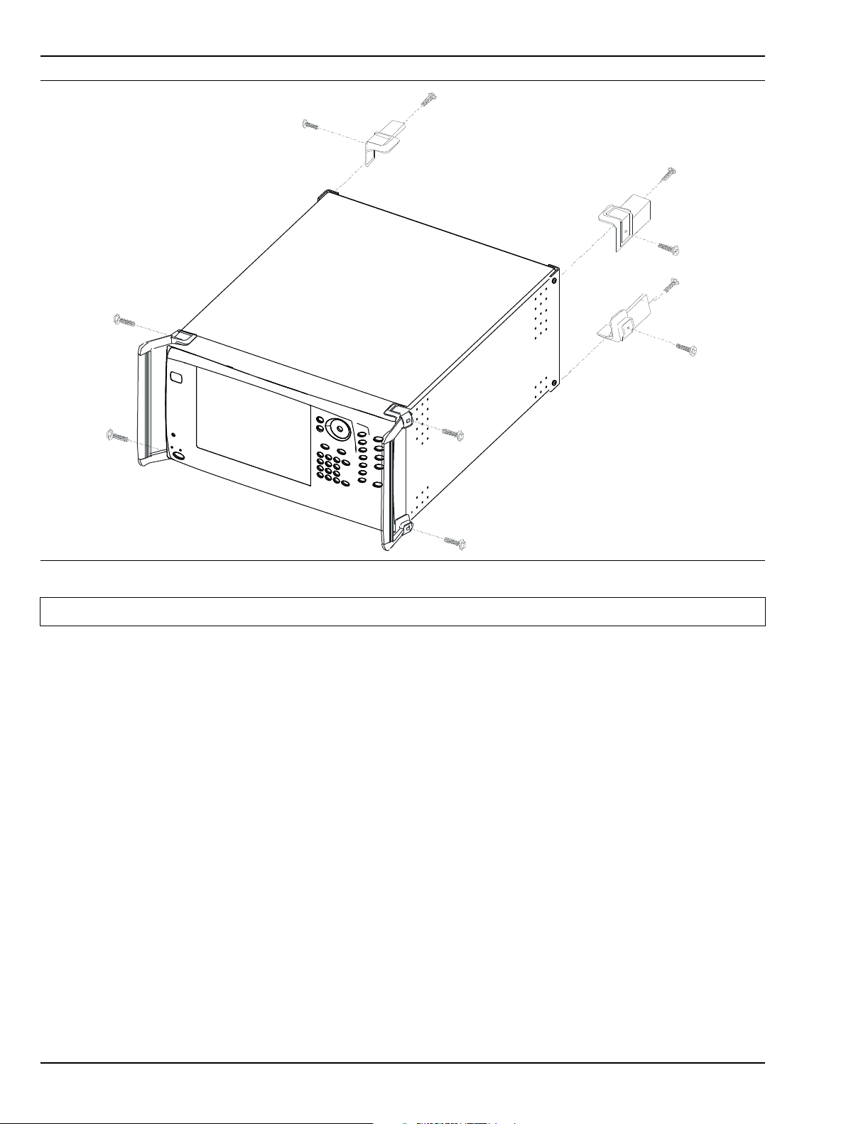
2-3 Optional Rack Mount Installation Installation
Figure 2-1. Removing Instrument Handles and Feet for Rack Mount
Note The rack installation figures are for generic instruments and may differ in general appearance.
2-2 PN: 10410-00266 Rev: L MS4640A Series VNA OM

Installation 2-3 Optional Rack Mount Installation
4. Install the rack mount bracket onto the instrument sides using the green-headed screws removed earlier
(see Figure 2-2).
Figure 2-2. Attaching Rack Mount Ears to Instrument
5. This completes the installation of the rack mount handles.
MS4640A Series VNA OM PN: 10410-00266 Rev: L 2-3

2-4 Installing and Configuring the Additional Solid State Drive Installation
2-4 Installing and Configuring the Additional Solid State Drive
The MS4640A-004 Additional Solid State Dr ive (SSD) provides the capability of using a different SSD for
different measurement tasks, and then to be able to quickly remove the measurement data and store it a
secure location. A separate SSD drive can be quickly installed in instrument, freeing it for other tasks or to
accompany the instrument back to the factory for recalibration.
Using multiple removable SSDs makes the VectorStar VNAs ideal for secure environments. The
Note
The MS4640A-004 SSD is factory-configured to the same specification as the instrument’s original hard drive.
Both drives provide the factory as-shipped instrument configuration, setup, and calibration information.
To use the Additional SSD, the general process is to copy any user setup, data, and calibration files from the
original SSD to the optional SSD while outsid e the secure environment. Then, when configured, move the SSD
into the secure environment.
Procedure
1. Prior to the hard drive replacement, copy and save any user setup, data, or calibration files to a USB
Memory Device.
2. Make sure also that the following hardware calibrations are copied from the C:\AnritsuVNA\Data
folder:
3. When all files are copied, power down the instrument and turn it off.
4. On the Rear Panel, loosen the two captive screws anchoring the SSD in place.
5. Remove the orignial SSD, insert into an anti-static bag or container, and store in a safe place.
hard drive can be left in the secure environment, and the instrument chassis moved to a different
location where another SSD can be installed, maintaining instrument usage. The internal memories
of the instrument retain no user data after the SSD has been removed.
• AlcCal.alc
• AllHWCal.ahc
• AnalogInCal.alc
• LOCal.slc
• SqmPowerCal.sqm
• tenMHzCal.tmc
• If the instrument is in the Operate mode (the green Operate LED is on), from the front panel, press
and hold the left side Standby/Operate key for at lease one (1) second.
• The green Operate LED turns off and the orange St andby LED turns on, indicating the instrument
is in Standby mode.
• From the rear panel, use the AC Power Rocker Switch to turn the instrument off by pressing the
“O” side of the rocker switch.
6. Slide in the replacement SSD. You will feel a slight resistance the last few millimeters as the connector
seats. Do not force.
7. Tighten the captive screws evenly on both sides of the drive.
8. Power up the system and it should boot as before the change.
• From the rear panel, use the AC Power Rocker Switch to turn the instrument on by pressing the
“|” side of the rocker switch.
• The orange Standby LED turns on, indicating the instrument is in S tandby mode. When the orange
Standby LED is on steady and not blinking, from the front panel, press and hold the left side
Standby/Operate key for at lease one (1) second.
• The orange Standby LED turns off and the green Operate LED turns on, indicating the instrument
is in Operate mode.
2-4 PN: 10410-00266 Rev: L MS4640A Series VNA OM

Installation 2-5 Connecting External Devices
The Option-004 Additional Solid S tate Drive drive is shipped in the same configuration as the instrument’s as-
shipped drive.
2-5 Connecting External Devices
After unpacking, the MS4640A Series VNA ready for u se although it is strongly recommended that you connect
an external keyboard and mouse to facilitate ease of use of the VectorStar VNA application and operating
system. The VNA also supports the connection of an XGA/VGA monitor, printer, and many other Windowsbased peripherals. In general, most peripherals are rated as plug-and-play with no driver installation or
further configuration required.
Connecting an External Mouse or Keyboard
The VNA provides USB Type A and PS/2 DIN connector ports for external keyboard and mouse interfaces.
USB Type A connectors are available on both the front and rear panels; PS/2 connectors are only available on
the rear panel. If the USB Type A connectors are needed for other devices, a USB keyboard/mouse can be
connected through the PS/2 connector by using a user-provided USB to PS/2 adapter connector.
When connecting either a keyboard and/or mouse, ensure that the instrument is set to standby mode before
connecting them. When the MS4640A Series VNA is set to Operate, the keyboard and mouse should be
automatically detected by the operating system and be ready for use. To use any advanced features of your
external keyboard and mouse, follow the manufacturers installation instructions.
Note
A USB mouse may require a hot connection while the instrument is in the Operate mode with the
VectorStar VNA Application software running. If a USB mouse fails to opera te when the instrument is
started with the mouse plugged into the USB port, reboot the instrument with the mouse
disconnected and make the hot connection after the VectorStar VNA Application software is running.
MS4640A Series VNA OM PN: 10410-00266 Rev: L 2-5
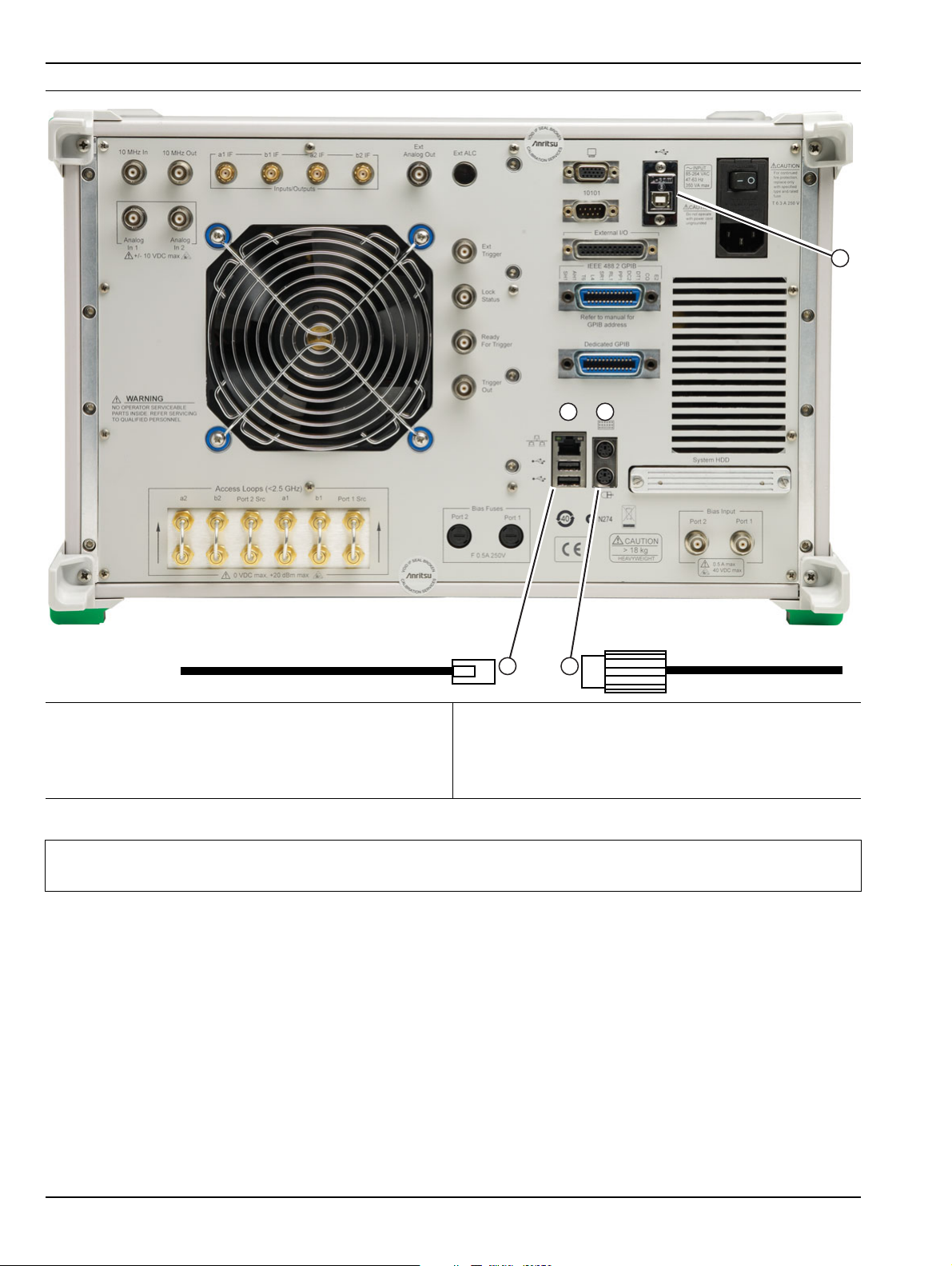
2-5 Connecting External Devices Installation
1
2
3
4
5
1. Rear Panel USB Type A Ports – Also two Type A
Ports on Front Panel.
2. USB Cable.
4. PS/2 Cable.
5. USB Type B Control Port – For VNA control over a
USB network.
3. Rear Panel PS/2 Port.
Figure 2-3. Rear Panel Keyboard and Mouse Connections
Note
Advanced keyboard and mouse features may not be supported in the analyzer application, but
should function as expected in the Windows environment.
There are two rear panel USB 2.0 Type A Ports (also two on front panel) that can be used for USB connections
for a USB mouse or keyboard. In addition, there are two rear panel PS/2 Ports with Mini-DIN (f) connectors for
keyboard (top) and mouse (bottom) connections using a PS/2 Mini-DIN (m) connector and cable.
Connecting an External XGA/VGA Monitor
The rear panel XGA/VGA Video Port external monitor interface is a standard XGA/VGA DB-15 Mini-DIN (f)
connector. When connecting an external monitor, ensure that the instrument is in standby mode and that the
monitor is disconnected from its power source. Once the monitor is connected, turn on its power and then set
the VNA to Operate. The monitor should be automatically detected by the operating system and be ready for
use.
2-6 PN: 10410-00266 Rev: L MS4640A Series VNA OM

Installation 2-5 Connecting External Devices
Connecting an External Printer
The external printer interface is typically connected through an available front or rear panel USB Type-A Port.
Many printers will be recognized by the Windows operating system and require no further installation.
If installation and configuration is required, install your printer driver according to the manufacturer’s
directions. The hardware connection should be made when the VNA is in Standby or Off mode to allow for
proper initialization of the hardware during boot-up of the operating system.
If you attempt to print from the VNA application before a printer is installed, a dialog box appears prompting
you to install a printer.
Connecting Other USB Peripherals
Use any available USB 2.0 Type A Port for connecting other USB devices such as a scanner, hard drive,
camera, or USB memory device (a “memory stick”). The USB interface offers the same behavior that is
typically experienced in the Windows operating system environment.
If connection of multiple USB devices is considered, the use of a user-supplied powered USB hub is
recommended. If the USB Type A Ports are required for other devices, an attached USB keyboard and/or USB
mouse can be attached to the rear panel Keyboard/Mouse PS/2 ports by using a user-supplied USB to PS/2
Adapter.
MS4640A Series VNA OM PN: 10410-00266 Rev: L 2-7

2-6 Operating Environment and Power Requirements Installation
2-6 Operating Environment and Power Requirements
Before installing the VectorStar MS4640A Series VNA in its operating environment, ensure that all airflow
passages at the sides and rear of the instrument are clear. Proper ventilation is of particular importance
whenever the unit is being rack mounted. Keep the cooling fan filters clean so that the ventilation holes are not
obstructed. A blocked fan filter can cause the instrument to overheat and shut down. The MS4640A Series
VNA can be operated within the following environmental limits:
Table 2-1. Operational Environmental Specifications and Power Requirements
Parameter Specification
Environmental Specifications
Operating Temperature Range: 0 to +50 degrees Celsius (per MIL-PRF-28800F)
Relative Humidity: 5% to 95% (per MIL-PRF-28800F)
Altitude: 4,600 meters, 43.9 cm Hg
Vibration: Sinusoidal 5 Hz to 55 Hz on 3 axes
Power Requirements
Voltages: 90 to 264 VAC maximum (single phase)
Frequency: 47 to 63 Hz (power factor controlled)
Power: 350 VA maximum
Installation Category: The MS4640A Series VNA is intended for
Installation Category (Overvoltage Category) II
Warning
When supplying power to this equipment, connect the accessor y 3-pin power cord only to
a 3-pin grounded power outlet connected in turn to local AC Mains. If a grounded 3-pin
outlet is not available, use a conversion adapter and ground the green wire, or connect
the equipment frame to a suitable ground. If power is supplied without grounding the
equipment, there is a risk of receiving a severe or fatal electric shock.
2-8 PN: 10410-00266 Rev: L MS4640A Series VNA OM
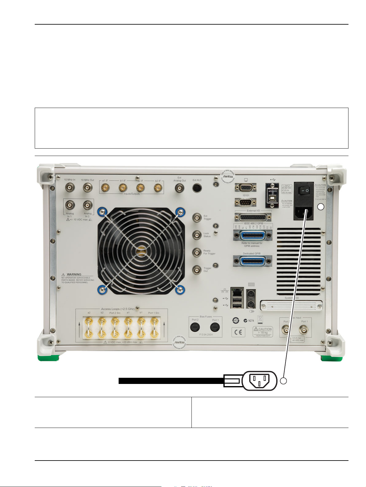
Installation 2-7 Power-On/Power-Off Procedures
1
2
2-7 Power-On/Power-Off Procedures
The power-on procedure involves connecting the instrument to AC Mains, using the back panel AC Power
Rocker Switch to turn the instrument on, and then using the front panel Standby/Operate key to toggle the
instrument into operate mode. The power-off procedure involves using the front panel Standby/Operate key to
toggle the instrument into standby mode, and then using the back panel AC Power Rocker Switch to turn the
instrument off.
During the transition from operate to standby, first the green Operate LED blinks and then the orange
Standby LED blinks. Finally, the Standby LED stops blinking and goes into a steady state of illumination.
Do not turn the instrument off or unplug it while it is changes from standby to operate, or from
operate to standby.
Note
Do not turn the instrument off or unplug it when it is in operate mode.
Doing so may cause the Windows application to improperly close.
1. The AC Power Entry Module contains the rear panel
AC Power Rocker Switch (at top) and the IEC C14 AC
Power Socket (m) (at bottom).
2. The AC Mains Connection is made with an AC Input
Cable connected to local AC mains power at one end
and to the instrument using the IEC C13 AC Line
Socket at the other end.
Figure 2-4. Rear Panel Power Connection to AC Mains Power
MS4640A Series VNA OM PN: 10410-00266 Rev: L 2-9

2-7 Power-On/Power-Off Procedures Installation
Procedure – Power-On to Standby Mode
To turn the instrument on:
1. Connect the supplied AC power cord to local AC mains power.
2. Connect the other end of the power cord to the rear panel IEC C14 Chassis AC Power Socket located in
the upper right corner of the rear panel.
3. Switch the instrument on by changing the AC Power Rocker Switch to “|” (or ON). The orange Standby
LED illuminates. The instrument is now in standby mode.
Whenever the VNA is not being used, it should be left connected to the power source and placed in
standby mode. This keeps the internal time-base frequency reference at the correct operating
temperature.
Note
When the instrument is in standby mode, it is safe to turn it of f from the rear p anel AC Power Rocker
Switch.
After turning off the instrument, you must wait at lea st 15 seconds before turning the in strument back
on again. This delay is required to allow the internal power supplies to discharge and to assure a
reliable cold start.
Procedure – Standby Mode to Operate Mode
To set the instrument to operate mode:
1. Press and hold the front panel Standby/Operate key for at least one second. The orange Standby LED
turns off and the green Operate LED illuminates. The VectorStar VNA information splash screen is
displayed during the change to operate mode process and is shown below in Figure 2-5, “MS4640A Series
VNA Startup Splash Screen”.
The MS4640A Series VNA requires at least two minutes to load the system software and perform a
Note
2. When fully in operate mode, the MS4640A Series VNA displays the main channel and trace display with
the application menus on the right side. See Figure 4-1, “User Interface - Single Channel - Four Traces”
for a typical full screen display.
Note
series of internal calibrations. The system uses a self-test to check all sub-systems for proper
operation and download firmware into the various peripheral devices.
When the instrument is in operate mode, do not use the rear panel AC Power Rocker Switch to turn
off the instrument nor disconnect the instrument from the AC power. Doing so will cause the
Windows application to close improperly.
When placing the MS4640A Series VNA in operation, allow at least 90 minutes of warm-up time in
the operate mode before using the VNA to assure stable operation and the high est possible
accuracy.
2-10 PN: 10410-00266 Rev: L MS4640A Series VNA OM
Installation 2-7 Power-On/Power-Off Procedures
Figure 2-5. MS4640A Series VNA Startup Splash Screen
Procedure – Operate Mode to Standby Mode
To set the instrument to standby mode from operate mode:
1. Press and hold the front panel Standby/Op erate k ey fo r at least one se cond. The green Oper ate LED
blinks and then the orange St and by LED blinks. The instrument switches from operate mode to standby
mode.
2. When fully in standby mode, the orange Standby LED is illuminated and is not blinking.
Note
Do not disconnect the instrument from power nor turn off with the AC Power Rocker Switch while
the instrument is changing from operate mode to standby mode.
Procedure – Standby Mode to Power-Off
To turn the instrument off:
1. Make sure that the instrument is in standby mode. The orange S tandby LED should be illuminated and
not blinking.
2. Turn off the instrument by pressing the “O” (or OFF) on the rear panel AC Power Rocker Switch.
3. If necessary, the instrument can now be disconnected from the AC power mains.
After turning off the instrument, you must wait at least 15 seconds before turning the instr ument back
Note
on again. This delay is required to allow the internal power supplies to discharge and to assure a
reliable cold start.
MS4640A Series VNA OM PN: 10410-00266 Rev: L 2-11

2-8 GPIB Setup Installation
External Source Synthesizer #1
Dedicated
GPIB
Port
VectorStar
MS4640A
VNA
External Source Synthesizer #4
External Source Synthesizer #3
External Source Synthesizer #2
1
2
3
4
6
5
2-8 GPIB Setup
The interface between the MS4640A Series VNA and other devices on the GPIB is via a standard 24-wire GPIB
interface cable. This cable uses a double-sided connector where one connector face is a plug and the other a
receptacle. These double-function connectors allow parallel connection of two or more cables to a single
instrument connector.
Caution
When two or more cables are connected in parallel, do not bend the attached connectors as this
could damage the rear panel GPIB Port connector.
Configuring the Dedicated GPIB Port
Use this procedure to set up the dedicated GPIB port to control other GPIB devices such as Power Meters or
Signal Generators by using the VNA rear panel Dedicated GPIB Port. An example of a complex GPIB
configuration with the VNA as the GPIB controller is shown in Figure 2-6.
1. Ve ctorSt ar MS4640A Series VNA.
2. Rear Panel Dedicated GPIB Port and GPIB Cable.
3. Synthesizer GPIB address 4 as External Source #1.
Figure 2-6. VNA as a Remote GPIB Controller for Synthesizers
2-12 PN: 10410-00266 Rev: L MS4640A Series VNA OM
4. Synthesizer GPIB address 5 as External Source #2.
5. Synthesizer GPIB address 2 as External Source #3.
6. Synthesizer GPIB address 3 as External Source #4.

Installation 2-8 GPIB Setup
1
2
1. Connect GPIB devices to the VNA rear panel Dedicated GPIB Port using the appropriate length GPIB
cable.
1. Rear Panel Dedicated GPIB Po rt for control of
2. GPIB Cable Connection to peripheral devices.
connected external sources, power meters, and
frequency counters.
Figure 2-7. MS4640A Series VNA Dedicated GPIB Port
2. Power-up the MS4640 A Series VNA and any attached GPIB devices, and allow the system to warm up for
at least 90 minutes.
3. Navigate to the REMOTE INTER menu:
• MAIN | System | SYSTEM | Remote Interface | REMOTE INTER.
• Figure 2-8, “REMOTE INTER (REMOTE INTERFACE) Menu” on page 2-14
MS4640A Series VNA OM PN: 10410-00266 Rev: L 2-13

2-8 GPIB Setup Installation
• A detailed menu description is located in the User Interface Manual – 10410-00307.
On the REMOTE INTER. (REMOTE INTERFACE) menu:
The IEEE 488.2 Interface, Ext. Sources, Ext. Power
Meter, Ext. Freq Counter, and the Multiport Test Set
The Ext. Sources button displays the EXT. SRC. ADDR.
menu where GPIB addresses are assigned for external
source 1 through external source 4.
buttons control GPIB addresses for the subject devices.
Figure 2-8. REMOTE INTER (REMOTE INTERFACE) Menu
4. The GPIB address for any controlled device can be kept at the factory default val ues or changed a s
required. The default GPIB addresses are:
• External Source 1 = 4
• External Source 2 = 5
• External Source 3 = 2
• External Source 4 = 3
• Power Meter = 13
• Wide Band Power Meter = 15
• Frequency Counter = 7
• Multiport Test Set = 16
• Only available when a MN4694B or MN4797B Multiport/4-Port Test Set is installed.
• The test set must be on and the VNA must be rebooted for any GPIB address change to take
effect.
2-14 PN: 10410-00266 Rev: L MS4640A Series VNA OM

Installation 2-8 GPIB Setup
• See the VectorStar MN4690B Multiport Test Set Installa tion Guide – 10410-00528 for
complete installation and configuration instructions.
• The VectorStar instrument itself = 6
5. The GPIB addresses for the External Sources ar e changed on the EXT. SRC ADDR. (EXTERNAL SOURCE
ADDRESS) sub-menu shown below in Figure 2-9.
• MAIN | System | SYSTEM | Remote Interface | REMOTE INTER. | Ext. Sources | EXT. SRC. ADDR
• A detailed description of the menu is available in the User Interface Manual – 10410-00307.
Figure 2-9. EXT. SRC. ADDR. (EXTERNAL SOURCE ADDRESS) Menu
6. If a change of GPIB address is required, click the device button, an d the device field toolbar app ears as
shown below:
7. Use the front panel keys, a keyboard, or mouse to set the required GPIB address.
8. Click the Enter button to set the new GPIB address.
For information on the programming command sets, refer to the VectorStar MS4640A Series VNA
Programming Manual – 10410-00267.
MS4640A Series VNA OM PN: 10410-00266 Rev: L 2-15

2-8 GPIB Setup Installation
1
2
Configuring the IEEE 488.2 GPIB Port
Use this procedure to set up the talker/listener port to control the VNA remotely over a n IEEE 488.2 GPIB bus
network. In this configuration, an external computer/controller is physically connected to the VNA rear panel
IEEE 488.2 GPIB Port with a standard GPIB cable. Most of the MS4640A Series VNA functions (except power
on/off and initialization of the hard disk) can be controlled remotely by an external computer/control ler via the
IEEE-488.2 GPIB bus network.
1. Connect the VNA to the GPIB Controller using the rear panel IEEE 488.2 GPIB Port DB-24 (f) connector
and a standard GPIB cable.
1. 1. IEEE 488.2 (Upper) Port 2. GPIB Cable Connection. Note that the Dedicated
GPIB Port is not used in this configuration.
Figure 2-10. IEEE 488.2 GPIB Talker/Listener Ports
2. Apply power to the MS4640A Series VNA and allow the system to warm up for at least 90 minutes.
3. Once the software has finished loading and start-up testing is complete, the instrument is ready to be
remotely controlled via the GPIB. The instrument will not respond to GPIB commands until the
instrument’s software has been loaded.
Note The factory default GPIB address for the instrument is six (6).
2-16 PN: 10410-00266 Rev: L MS4640A Series VNA OM

Installation 2-8 GPIB Setup
Configuring the VectorStar VNA GPIB Address
To change the VectorStar VNA GPIB address:
1. Navigate to the REMOTE INTER. menu:
• MAIN | System | SYSTEM | Remote Interface | REMOTE INTER.
2. On the REMOTE INTER menu, the IEEE 488.2 GPIB button.
The IEEE 488.2 GPIB toolbar appears below the icon toolbar near the top of the display.
3. Use the front panel keys, a keyboard, or a mouse to set the required GPIB address.
4. Click the Enter button to set the new GPIB address.
For information on the programming command sets, refer to the:
• VectorStar MS4640A Series VNA Programming Manual – 10410-00267
• VectorStar MS4640A Series VNA Programming Manual Supplement – 10410-00308
MS4640A Series VNA OM PN: 10410-00266 Rev: L 2-17

2-9 Ethernet LAN TCP/IP and USB Setup Installation
2-9 Ethernet LAN TCP/IP and USB Setup
The MS4640A Series VNA supports Ethernet 10/100 BASE-T. The instrument is connected directly to the LAN
via the rear panel RJ-45 Ethernet Port using a standard CAT-5 Ethernet cable. The MS4640A Series VNAs
can also be controlled remotely across a Universal Serial Bus (USB) Type 2 network by a PC equipped with a
USB control application using the rear panel USB Control Port.
Default Plug-and-Play Configuration
The MS4640A Series VNA and its Windows operating system comes pre-configured and ready to plug into and
connect with an existing Ethernet or USB network. The Ethernet network must provide DNS/DHCP and be
configured with a gateway. USB networks are typically auto-detecting without the need for configuration;
however, a special USB network cable (described in the note below) is required.
The required PC-to-Instrument USB 2.0 networking cable (also called a USB-USB cable, USB
networking cable, or USB bridge cable) has a small electronic circuit module in the middle of th e
Note
Warning
cable that allows the PC and the VectorStar VNA to talk to each other at 480 Mbps. The PC-toInstrument USB cable is user-provided and does not come with the VectorStar MS4640A Series
VNA.
Using the wrong type of USB-USB cable can result in damage to the PC and/or VectorStar USB
ports and/or power supplies. Do NOT use a so-called “USB A / A” cable that is similar to a serial port
cross-over null-modem cable.
2-18 PN: 10410-00266 Rev: L MS4640A Series VNA OM

Installation 2-9 Ethernet LAN TCP/IP and USB Setup
1
2
Connect the VNA to the network with an Ethernet cable between the VNA rear panel RJ-45 Ethernet Port and
your local network port or a USB network cable between the VNA rear panel USB Type 2 Port and your local
network hub.
1. Rear Panel Ethernet Port (at top) and USB Ports (at
2. Matching USB or Ethernet Connection Cable.
bottom).
Figure 2-11. MS4640A Series VNA Ethernet and USB Ports
The MS4640A Series VNA has one Ethernet RJ45 (f) connector and two (2) with USB 2.0 Type A port
connectors. There are two additional USB 2.0 Type A ports on the instrument front panel. Use the Ethernet
port to connect to a LAN (Local Area Network). Windows will automatically detect the network settings and
configure the network connection.
Manually Configuring TCP/IP Ethernet LAN Settings
This section is provided for general information about manually configuring an Ethernet connection
Note
To see the current network settings for your MS4640A Series VNA, with the VectorStar Application Software
running, navigate to the NETWORK INTERF. (Network Interface) menu as follows (see Figure 2-12 ):
• MAIN | System | SYSTEM | Ntwk Interface | NETWORK INTERF.
and does not apply to USB networking. Consult your local network administrator for the exact
requirements and settings that are required for your network installation.
MS4640A Series VNA OM PN: 10410-00266 Rev: L 2-19

2-9 Ethernet LAN TCP/IP and USB Setup Installation
The detailed description of the menu, its operation, and connected dialog boxes are described in the User
Interface Manual – 10410-00307.
Figure 2-12. NETWORK INTERF. (NETWORK INTERFACE) Menu
The top eight (8) display buttons provide information for the current network settings. Changes to these
settings must be made through the Microsoft Windows configuration utilities by clicking the Network
Connections button.
2-20 PN: 10410-00266 Rev: L MS4640A Series VNA OM
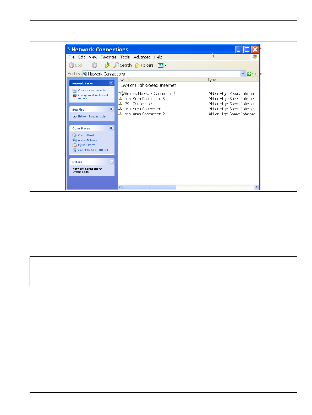
Installation 2-9 Ethernet LAN TCP/IP and USB Setup
The NETWORK CONNECTIONS dialog box shows the current available local networks,
Figure 2-13. NETWORK CONNECTIONS Dialog Box
It provides access to various network configuration utilities and setup wizards as follows:
• A link to the Create a new connection wizard
• A link to the Network Troubleshooter wizard
• If connected to one or more networks, a link to each network name is provided with links to the settings
of each connection
You may need to consult your network documentation or network administrator for assistance in
Note
manually configuring your network setup. The Network Connections Help system provides
information related to computer networking. If an Internet connection is present, links to Microsoft
and other URLs are also provided.
For information on the programming command sets, refer to the:
• Vec torStar MS4640A Series VNA Programming Manual – 10410-00267
• Vec torStar MS4640A Series VNA Programming Manual Supplement – 10410-00308
MS4640A Series VNA OM PN: 10410-00266 Rev: L 2-21

2-10 Configuring the Remote Language Installation
2-10 Configuring the Remote Language
The MS4640A Series VNA command parser responds to either Native SCPI commands or to the legacy Anritsu
Lightning-model command set. The MS4640A VNAs also support many HP/Agilent 8510 programming
commands.
Regardless of the setting, the MS4640A VNA parser will respond to commands from either source.
Scripts written in older versions of the Lightning command set or in the HP/Agilent 8510 command set may
need editing to be fully compatible with the VNA. Not all Lightning and HP/Agilent commands are supported.
Processing and response times will be improved if the Remote Language setting matches the majority of the
sent commands.
If necessary, you can change the VNA default GPIB language from Native to Lightning or HP/Agilent 8510x as
follows:
1. Navigate to the Remote Lang. menu:
• This menu is described in greater detail in the User Interface Manual – 10410-00307.
• MAIN | System | SYSTEM | Remote Interface | REMOTE INTER. | Language Selection | REMOTE
LANG.
Figure 2-14. REMOTE LANG. (REMOTE LANGUAGE) Menu
2. Select the interface language being used.
3. The menu auto-returns to the REMOTE INTER menu.
2-22 PN: 10410-00266 Rev: L MS4640A Series VNA OM

Installation 2-11 Calibration/Verification Interval
2-11 Calibration/Verification Interval
If the MS4640A Series VNA requires service or calibration, the system may be returned to factory
specifications and re-imaged with a standard software configuration. User installed applications and data may
be lost and unable to be retrieved. It is advised that user data be backed up, copied, and retained by the user.
Applications will need to be reinstalled from their original installation disks. A complete system restore from a
previous user backup is not advised after service or calibration as this will result i n the new calibrations being
overwritten, thus voiding the calibration accuracy.
2-12 Fuse Maintenance
The MS4640A Series VNA requires periodic cleaning of the cooling fan screen to prevent an obstruction that
could facilitate overheating. Additional maintenance that may be required includes replacing a blown fuse,
replacing the CPU backup battery, and cleaning the LCD panel. The final part of this sections defines how to
restore the VectorStar C:\drive application in the event the operating system becomes corrupted or
inoperable.
Fuse Summary
The MS4640A contains six (6) fuses, four (4) external and two (2) internal.
External Fuses
There are two sets of rear panel fuses available for fi eld repl ace m en t.
• AC Power Input Fuses
Two fuses located inside the IEC C14 AC Power Entry Module connector rated at T 6.3 A, 250 V.
• Bias Input Fuses
Two fuses, one per port, located inside the twist-off fuse holders rated at F 0.5 A, 250 V, quick acting.
Internal Fuses
Internal fuses are not replaceable at the field level. They are mounted within the field-replaceable power
supply module. Internal fuse information is provided for reference only.
• Internal Fuse #1
Rated at 6.3 A, 250 V, F (quick acting)
• Internal Fuse #2
Rated at 15 A, 32 Vdc (automotive type).
External Rear Panel AC Input Fuses
The AC line fuses used in the MS4640A Series VNA are 6.3A, type T fuses. The line fuse values are printed on
the rear panel next to the power connector. Always use a new fuse of the type and rating specified by the fuse
markings on the rear panel of the instrument. To replace the line fuses, refer to Figure 2-15 and follow the
procedure steps below.
Danger
Before changing the fuse, always remove the power cord from the power outlet. There is the risk of
receiving a fatal electric shock if the fuse is replaced with the power cord connected.
1. Set the MS4640A Series VNA to standby mode using the front panel Power b utton, and, at the bac k
panel, turn the instrument off by using the AC Power Entry Module On/Off switch.
2. Disconnect the power cord from the rear panel power receptacle.
3. Using a small flat-blade screwdriver, carefully pry under the tab next to the rear panel power receptacle
to open the fuse block cover and gain access to the fuse holder.
4. Slide out the fuse holder.
MS4640A Series VNA OM PN: 10410-00266 Rev: L 2-23
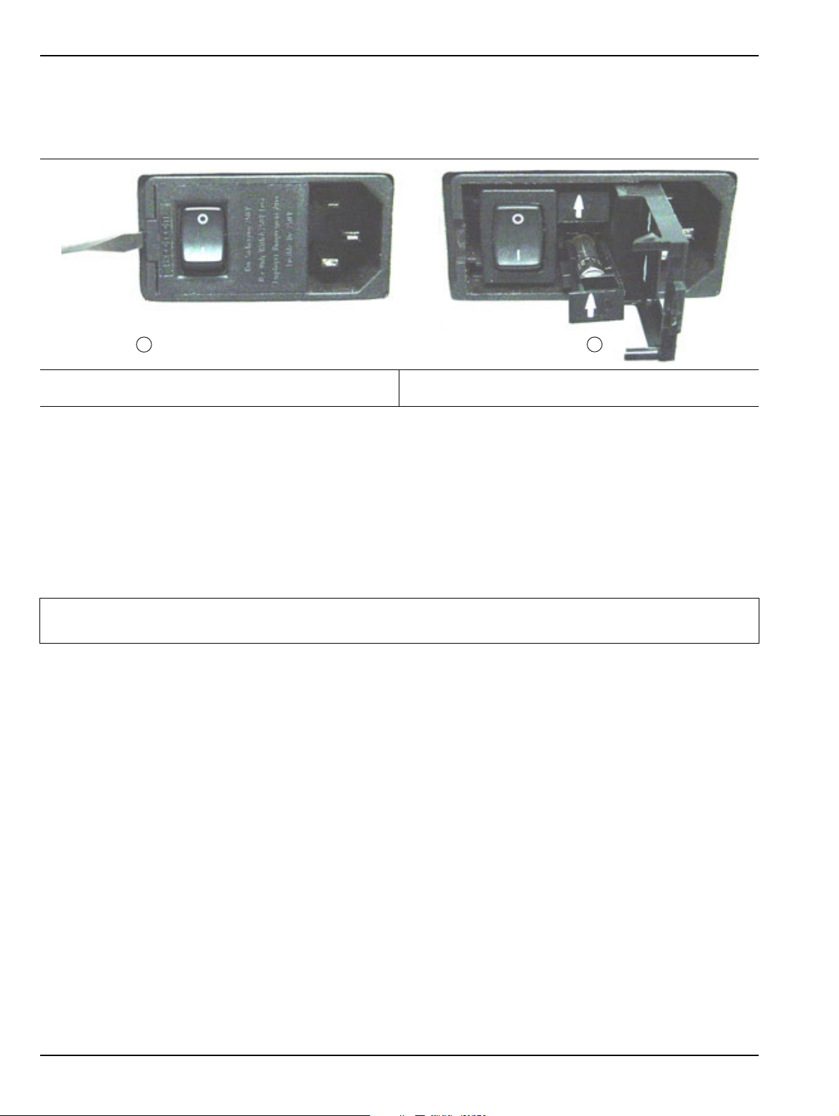
2-12 Fuse Maintenance Installation
1
2
5. Replace the fuse in the fuse holder.
6. Install the fuse holder back into the rear panel fuse block.
7. Close the cover to secure the fuse holder in place. The cover will close with an audible snap.
1. Opening the Rear Panel Fuse Holder with a flat blade
2. Sliding out and replacing a fuse.
screwdriver.
Figure 2-15. Replacing the Rear Panel Fuse
8. Reconnect the analyzer to the power source and turn the back panel On/Off switch to on.
9. At the front panel, set the MS4640A Series VNA to operate using the front panel Power button.
Bias Fuse Replacement
The required replacement Bias Port fuses used in the VectorStar MS4640A Series VNAs are printed on the
rear panel below the Bias Port Fuse Holders. Always use a new fuse of the type and rating specified by the
fuse markings on the rear panel of the instrument. To replace the bias fuses, follow the procedure steps below.
Danger
1. Set the MS4640A Series VNA to standby mode using the front panel Power button, and, at the back
panel, turn the instrument off by using the AC Power Entry Module On/Off switch.
2. Disconnect the power cord from the rear panel power receptacle.
3. Remove any DC biasing from the DC Bias Inputs.
4. Using a small flat-blade screwdriver, unscrew the each Bias Fuse Holder.
5. Slide out fuse holder.
6. Remove the fuse.
Before changing the fuse, always remove the power cord from the power outlet. There is the risk of
receiving a fatal electric shock if the fuse is replaced with the power cord connected.
7. Replace the fuse in the fuse holder.
8. Install the fuse holder back into the rear panel fuse block.
9. Lightly tighten the fuse holder with the flat-blade screwdriver.
10. Reconnect the analyzer to the power source and turn the back panel On/Off switch to on.
11. At the front panel, set the VNA to operate using the front panel Power button.
2-24 PN: 10410-00266 Rev: L MS4640A Series VNA OM

Installation 2-13 Operating System Restore
2-13 Operating System Restore
The VectorStar VNA is configured with Windows Operating System Restore. This system can be accessed from
the Windows desktop Start menu and used to restore the VectorStar operating system to a recent known good
state.
The instrument is shipped with a “Point of Shipment” restore point. Additional restore points are created when
the VectorStar application is updated, other user applications are installed, when new or updated hardware
drivers are installed, or when restore points are created manually. Restore points are saved for a limited time,
so the system should be restored as soon as problems are discovered.
Note
In the event that the VectorStar operating system or application becomes corrupt or inoperable, the
instrument must be returned to a qualified service center for repair.
Caution
For detailed information about system restore and additional restore tasks, refer to the Windows
Operating System Help and Support as detailed in the procedure below.
Restoring the system software may adversely affect some user data or programs that are loaded
onto the instrument hard drive. The instrument operating system will be configured as it was on the
selected restore date, including the original option configuration. Before starting the system restore
procedure, back up all user data, applications, and ensure that the installation file s of any additional
software or instrument options are available for reinstallation.
Procedure
The following procedure should be performed with a mouse attached to the instrument.
1. Close the VectorStar application and reveal the operating system desktop by clicking:
File | Exit
2. To access the Operating System Help and Support for additional information on System Restore, move
the mouse pointer to the bottom of the desktop to reveal th e Windows Task Bar and click:
Start | Help and Support
Search for topics on “System Restore.”
3. Open System Restore by moving the mouse pointer to the bottom of the desktop to reveal the Windows
Task Bar and clicking:
Start | Programs | Accessories | System Tools | System Restore
4. If you are prompted for an administrator password or confirmation , enter the passw ord or provide
confirmation.
5. Follow the on-screen instructio ns to restore your computer to an earlier restore point shown on the
calendar. The most recent known good restore point should be used to restore the instrument operating
system.
6. Do not interrupt the restoration process once it has started.
MS4640A Series VNA OM PN: 10410-00266 Rev: L 2-25

2-14 Preparation for Storage or Shipment Installation
2-14 Preparation for Storage or Shipment
Use the following information for preparing the MS4640A Series VNAs for storage or shipment.
Preparation for Storage
Preparing the VNA for storage consists of cleaning the unit, packing it inside of the storage container with
moisture-absorbing desiccant crystals, and storing the unit in a temperature-controlled environment that is
maintained between –40 °C and +75 °C.
Preparation for Shipment
To provide maximum protection against damage in transit, the VNA should be repackaged in either the
optional VNA Transit Case – 760-246 or the original shipping container. If these containers are not available
and the unit is being returned to Anritsu for repair, advise Anritsu Customer Service and they wi ll send a new
shipping container free of charge. In the event these options are not possible, instructions for packaging and
shipment are given below:
Remove Attached Equipment and Connectors
1. Remove any user-supplied connectors or adapters. If installed, remove the rack mounting ears and
related hardware.
Use a Suitable Container
2. Obtain a corrugated cardboard carton with at least 125 kg test strength. This carton should have inside
dimensions of no less than 15 cm (6.0”) larger than the instrument unit dimensions to allow for
cushioning.
Dimensions
3. The instrument dimensions are:
• Height
267 mm body height (10.5”) - 286 mm between feet outer edges (11.3”)
•Width
426 mm body height (16.7”) - 457 mm between feet outer edges (17.9”), 487 mm between front
panel handle outer edges (19.2”)
•Depth
502 mm body depth (16.7”) - 591 mm between handle and foot outer edges (23.3”)
Protect the Instrument
4. Surround the unit with polyethylene sheeting to protect the finish. A sealed bag is recommended as a
best practice.
Cushion the Instrument
5. Cushion the instrument on all sides by tightly packing dunnage or urethane foam between t he carton and
the unit. Provide at least 8 cm (3.0”) of dunnage on all sides; best practices recommend completely filling
the space between the carton and instrument with dun nage.
Seal the Container
6. Seal the carton by using either shipping tape or an industrial stapler.
Address the Container
7. If the instrument is being returned to Anritsu for service, mark the address of the appropriate Anritsu
service center and your return address on the carton in one or more prominent locations.
8. Contact information for all worldwide Anritsu Service Centers is available on the Web site at:
http://www.anritsu.com/Contact.asp
2-26 PN: 10410-00266 Rev: L MS4640A Series VNA OM

Chapter 3 — Front and Rear Panels
3-1 Chapter Overview
The chapter provides an overview of the MS4640A Series VNA hardware user interface including front panel
buttons, front panel connectors, and back panel connectors. Included are photographs of the front and rear
panels. Each front panel key is described with its fun ction and a cross reference t o the menu it activates on the
user interface display. Each port and connector is described with its connector type, its function, input/output
limits, and a cross-reference to a detailed connector pin-out diagram.
3-2 Front Panel Touch Screen
The touch screen display shows the instrument measurement graphs and the system navigation menus. The
menus are available by using either the touch screen or a connected mouse and keyboard. A complete
description of the various display and menus appears in the chapters below.
When using the touch screen, a recommended best practice is to use a positive hard press to make
sure the required setting in input into the system. A light touch may not change the instr ument setting
as required.
To recalibrate the touch screen, navigate to the CALIBRA TE T OUCH SCREEN dialog box located at
Note
MAIN | System | SYSTEM | Utility | UTILITY | Calibrate T ouch Screen | TOUCH SCREEN
CONTROL PANEL dialog box. The procedure is described in the User Interface Manual – 10410 -
00307.
A more detailed touch screen calibration and adjustment procedure is described in the VectorStar
MS4640A Series VNA Maintenance Manual – 10410-00268.
MS4640A Series VNA OM PN: 10410-00266 Rev: L 3-1

3-3 Front Panel Hard Keys and Connectors Front and Rear Panels
6
9
10
7
8
1
2
3 4
11
5
12 151413
16 17
2019
18
3-3 Front Panel Hard Keys and Connectors
The MS4640A Series VNA front panel areas, keys, and port connectors are identified below in Figure 3-1.
Figure 3-1. MS4640A Series VNA Front Panel Hard Keys and Connectors (2 of 2)
3-2 PN: 10410-00266 Rev: L MS4640A Series VNA OM

Front and Rear Panels 3-3 Front Panel Hard Keys and Connectors
1. Model Number – Instrument model number
identification
2. Display Area – Touch screen with instrument test
results and graphics with the MENU BAR at top and
the ICON BAR immediately below. Th e MAIN menu
with access to specific-functions menus and dialog
boxes is on the right side. This area is also terms the
right-side application menus.
3. Data Entry – Data entry keypad with numbers from 0
(zero) to 9 (nine), Decimal Point, and
+/– (Plus/Minus).
4. Navigation Keys – Up, Down, Left, Right arrow
navigation keys and the center Select key.
5. Rotary Knob – Scrolls through values or changes
settings. Pressing it is the same function as the Select
key.
6. Channel Key – Select displays the Channel menu.
7. Analysis Key Group – Response, Display, Scale, and
Marker Keys. Select of each displays the named
menu.
8. Setup Key Group – Power, Sweep, and Avg Keys.
Select of each displays the named menu.
9. Measurement Key Group – Calibration,
Measurement, and Application Keys
10.System Key Group – System, File, and Help keys
11.Standby/Operate Key – Pressing and holding the key
for more than one (1) second toggles the VNA
between standby and operate modes. When in
standby mode, the orange Standby LED above the
key is illuminated. When in operate mode, the green
Operate LED above the key is illuminated.
12.Ground – Chassis Ground Port Banana connector
13.Direct Access Loops – b1 Front Panel Direct Access
Loop (left) and a1 Front Panel Direct Access Loop
(right).
14.Test Post Port 1 – K (f) on MS4642A and MS4644A
VNAs – V (f) on MS4647A VNAs.
15.Port 1 Direct Access Loop – Port 1 Source Front
Panel Direct Access Loop
16.Direct Access Loop – Port 2 Source Front Panel
Direct Access Loop
17.T e st Port 2 – Same connector types as for Test Port 1
above.
18.Direct Access Loop – a2 Front Panel Direct Access
Loop (left) – b2 Front Panel Direct Access Loop
(right)
19.USB Ports – Two USB 2.0 Type A Ports
20.Preset Key – The Preset key restores the instrument
to one of three prior states. User Defined: A
previously saved user-defined state. Default: The
factory as-shipped state. Default 0: The factory
original setting. The user selects which preset mode
is used.
Figure 3-1. MS4640A Series VNA Front Panel Hard Keys and Connectors (2 of 2)
MS4640A Series VNA OM PN: 10410-00266 Rev: L 3-3

3-3 Front Panel Hard Keys and Connectors Front and Rear Panels
Front Panel Hard Key and Connector Description
The front panel hard keys are described in Table 3-1 below. The cross reference links are to related information
in this chapter and detailed menu descriptions in separate chapters
Table 3-1. Front Panel Hard Keys and Functions (7 of 8)
Key Name Primary Functions
Power Key and Chassis Ground Connector
Standby/Operate Key Pressing and holding the S tand by/Operate key for a t least one (1) seco nd toggles the
VNA between operate mode and standby mode.
Power Up
To power up the VNA into Standby mode, connect the instrument to AC power and
then set the rear panel AC Power Rocker Switch (which is part of the upper right
corner AC Power Input Module) to “|” or ON. The orange Standby LED on the front
panel is illuminated and the Standby/Operate key is illuminated with an orange LED.
• “AC Power Connectors and Controls” on page 3-14 below.
Standby to Operate Mode
With the VNA in standby mode, to change to operate mode, press and hold the
Standby/Operate key for at least one (1) second. The green Operate LED is
illuminated and the Standby/Operate key is illuminated with a green LED.
Operate to Standby Mode
With the VNA in operate mode, to change to standby mode, press and hold the
Standby/Operate key for at least one (1) second. The orange Standby LED is
illuminated and the Standby/Operate key is illuminated with an orange LED.
Power Off
With the VNA in standby mode, to remove AC power from the VNA and turn the VNA
off, set the rear panel AC Power Rocker Switch to “O” or OFF.
Do not remove AC Power from the VNA while it is in operate mode. Do not turn of f the
VNA while it is in operate mode.
Chassis Grounding Port Provides an instrument chassis and signal grounding (earth) point.
Banana (f).
3-4 PN: 10410-00266 Rev: L MS4640A Series VNA OM

Front and Rear Panels 3-3 Front Panel Hard Keys and Connectors
Table 3-1. Front Panel Hard Keys and Functions (7 of 8)
Key Name Primary Functions
Calibration, Measurement, and Application Keys
Calibration Key Pressing Calibration displays the user interface CALIBRATION menu.
• MAIN | Calibration | CALIBRATION
Measurement Key Pressing Measurement displays the MEASUREMENT menu in the user interface
display.
• MAIN | Measurement | MEASUREMENT
Application Key Pressing Application displays the APPLICATION menu in the user interface display.
• MAIN | Application | APPLICATION
System, File, Help, and Preset Keys
System Key Pressing System displays the System menu in the user interface display.
• MAIN | System | SYSTEM
File Key Pressing File displays the File menu in the user interface display.
• MAIN | File | FILE
Help Key Pressing Help displays the Help menu in the user interface display.
• MENU BAR | Help | Context Sensitive Help
MS4640A Series VNA OM PN: 10410-00266 Rev: L 3-5

3-3 Front Panel Hard Keys and Connectors Front and Rear Panels
Table 3-1. Front Panel Hard Keys and Functions (7 of 8)
Key Name Primary Functions
Preset Key Returns the instrument (or presets it) to the last active configur ation preset loaded as
defined and set in the PRESET SETUP menu. Depending on the user-set preset
configuration, this can be either:
• User Defined: A previously saved user-defined state.
• Default: The factory as-shipped state.
• Default 0: The factory original setting.
The user selects which preset mode is used.
• MENU BAR | Utilities | Preset
• MAIN | System | SYSTEM | Setup | SETUP | Preset Setup | PRESET SETUP
Frequency, Power, and Sweep Setup Key Group
Frequency Key Pressing Frequency displays the FREQUENCY menu in the user interface display.
• MAIN | Frequency | FREQUENCY
Power Key Pressing Power displays the POWER menu in the user interface display.
• MAIN | Power | POWER
Sweep Key Pressing Sweep displays the SWEEP menu in the user interface display.
• MAIN | Sweep Setup | SWEEP SETUP
Average Key Pressing Avg displays the AVERAGING menu in the user interface display.
• MAIN | Averaging | AVERAGING
3-6 PN: 10410-00266 Rev: L MS4640A Series VNA OM

Front and Rear Panels 3-3 Front Panel Hard Keys and Connectors
Table 3-1. Front Panel Hard Keys and Functions (7 of 8)
Key Name Primary Functions
Response, Display, Scale, and Marker Key Group
Response Key Pressing Response displays the Response menu in the user interfa ce display. The
RESPONSE menu displayed depends on whether the instrument is in 2-Port or 4Port mode.
• MAIN | Response | RESPONSE
Display Key Pressing Display displays the Display menu in the user interface display.
• MAIN | Display | DISPLAY
Scale Key Pressing Scale displays the Scale menu in the user interface display.
• MAIN | Scale | SCALE menu
Marker Key Pressing Marker displays the Marker menu in the user interface display.
• MAIN | Marker | MARKERS [1]
Channel and Trace Key Group
Channel Key Pressing Channel displays the Channel menu in the user interface display.
• MAIN | Channel | CHANNEL
Trace Key Pressing Trace displays the Trace menu in the user interface display.
• MAIN | Trace | TRACE
MS4640A Series VNA OM PN: 10410-00266 Rev: L 3-7

3-3 Front Panel Hard Keys and Connectors Front and Rear Panels
Table 3-1. Front Panel Hard Keys and Functions (7 of 8)
Key Name Primary Functions
Navigation and Data Entry Keys
Rotary Knob The operation of the Rotary Knob varies depending on the cursor focus.
On selections, rotating the Rotary Knob clockwise moves the selection down.
Rotating counterclockwise moves the selection up.
On menus, moves the button focus up or down.
On field toolbars, increases or decreases the field value.
Pressing the Rotary Knob starts the action of the selected menu button or applies
the input value of the selected field toolbar .
Up Arrow Key Pressing Up moves the cursor or selection up.
Down Arrow Key Pressing Down moves the cursor or selection down.
Left Arrow Key Pressing Left moves the cursor or selection to the left.
Right Arrow Key Pressing Right moves the cursor or selection to the right.
Select Key Pressing Select starts the action of the selected menu button.
Same as pressing the Rotary Knob.
3-8 PN: 10410-00266 Rev: L MS4640A Series VNA OM

Front and Rear Panels 3-3 Front Panel Hard Keys and Connectors
Table 3-1. Front Panel Hard Keys and Functions (7 of 8)
Key Name Primary Functions
Keypad and Data Entry Key Group
Keypad Digit Keys Used to enter digits from 0 (zero) to 9 (nine). . (Decimal) Key Used to enter a decimal point. +/- (Plus/Minus) Key Toggles an entered value between + (plus) and – (minus). Backspace / Delete Key Deletes characters and moves the cursor to the left. Enter Key Causes the user-defined value or the field toolbar value to be entered into the
instrument.
Clear/Tab Key Clears the value of a field or tabs forward to the next field.
MS4640A Series VNA OM PN: 10410-00266 Rev: L 3-9
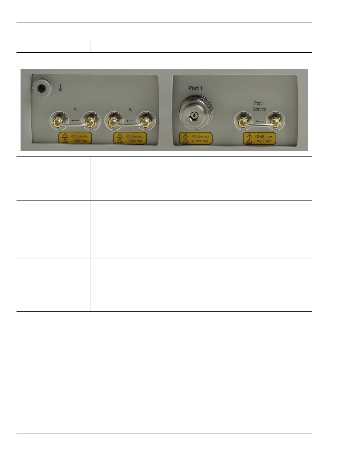
3-3 Front Panel Hard Keys and Connectors Front and Rear Panels
Table 3-1. Front Panel Hard Keys and Functions (7 of 8)
Key Name Primary Functions
Test Port 1 and Loop Connectors
Test Port 1 Universal Test Port Connector
• K (m) for MS4642A and MS4644A
• V (m) for MS4645A and MS4647A
• Damage Input Levels: +27 dBm max., 40 VDC max.
• Exchangeable in case of damage.
Port 1 Source Source paths, ≥ 2.5 GHz coverage.
• K (f) for MS4622A and MS4644A.
• V (f) for MS4645A and MS4647A.
• Damage Input Levels: +20 dBm max., 0 VDC max.
• Optional. Included with Option 051, 061, and 062. This port is also used to interface
with MN469xB Series 4-Port Test Sets and ME78x8x Series Broadband/Millimeter
Wave Systems.
b
Test Receiver - Port 1 Test receiver paths.
1
• As above.
• Optional. Included with Option 051, 061, and 062.
a
Reference Receiver -
1
Port 1
Reference receiver paths.
• As above.
• Optional. Included with Option 051, 061, and 062.
3-10 PN: 10410-00266 Rev: L MS4640A Series VNA OM
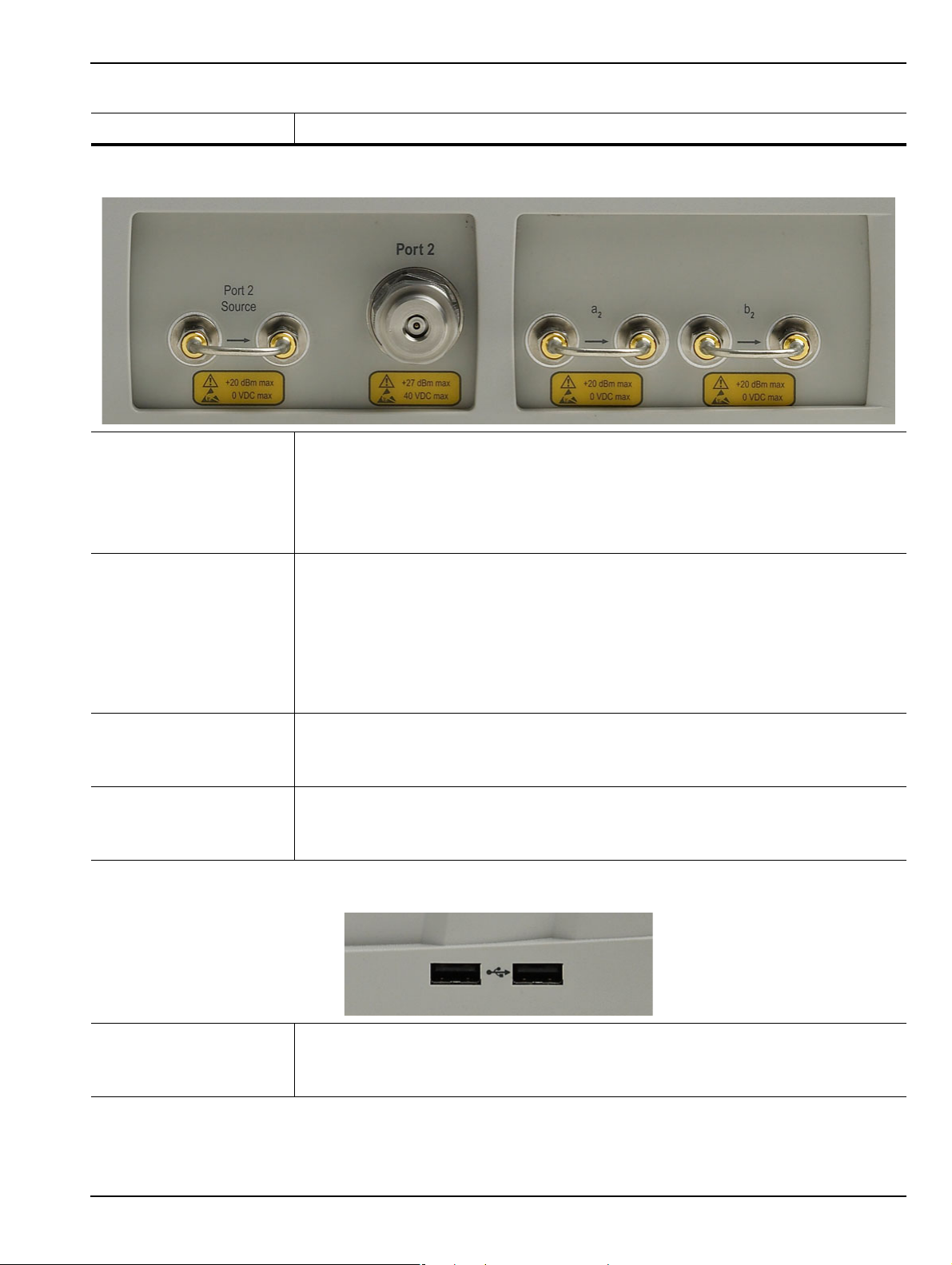
Front and Rear Panels 3-3 Front Panel Hard Keys and Connectors
Table 3-1. Front Panel Hard Keys and Functions (7 of 8)
Key Name Primary Functions
Test Port 2 and Loop Connectors
Test Port 2 Universal Test Port Connector.
• K (m) for MS4622A and MS4644A
• V (m) for MS4645A and MS4647A
• Damage Input Levels: +27 dBm max., 40 VDC max.
• Exchangeable in case of damage.
Port 2 Source Source paths, ≥ 2.5 GHz coverage.
• K (f) connectors for the MS4642A and MS4644A VNAs.
• V (f) connectors for the MS4645A and MS4647A VNAs.
• Damage Input Levels: +20 dBm max., 0 VDC max.
• Optional. Included with Option 051, 061, and 062. This port is also used to interface
with MN469xB Series 4-Port Test Sets and ME7828x Series Broadband/Millimeter
Wave Systems.
b
Test Receiver - Port 2 Test receiver paths.
2
• As above.
• Optional. Included with Option 051, 061, and 062.
a
Reference Receiver -
2
Port 2
Reference receiver paths.
• As above.
• Optional. Included with Option 051, 061, and 062.
Front Panel USB Ports
USB Ports USB 2.0 Type A Ports, two (2) each.
• For peripherals such as keyboard, mouse, memory stick, or hardware key.
• There are two additional USB 2.0 Type A Ports located on the rear panel.
MS4640A Series VNA OM PN: 10410-00266 Rev: L 3-11

3-4 Rear Panel Ports and Connectors Front and Rear Panels
10
2
4
5
1213
25
24
27 28
6
11
26
20
23
9
7
8
1
3
14
16 1719
18
21
22
15
3-4 Rear Panel Ports and Connectors
The MS4640A Series VNA rear panel connectors are shown below in Figure 3-2, “MS4640A Series VNA Rear
Panel Ports and Connectors (1 of 2)” on page 3-12 which provides identification of each connector and port.
Figure 3-2. MS4640A Series VNA Rear Panel Ports and Connectors (1 of 2)
3-12 PN: 10410-00266 Rev: L MS4640A Series VNA OM

Front and Rear Panels 3-4 Rear Panel Ports and Connectors
All ports and controls are standard and equipped on all
models unless otherwise noted.
1. AC Input Module Connector: Contains the AC Power
Rocker Switch, the AC Power Internal Fuses (located
under the switch), and the IEC C14 Chassis AC
Power Socket.
2. System SDD: The internal Solid State Drive.
3. USB 2.0 Type B Port: USB connection when
instrument is controlled by a USB controller.
4. USB 2.0 Ty pe A Ports: USB connection ports for
computer peripheral devices such as a printer,
keyboard, or mouse. Note that there two ( 2) additional
USB 2.0 Type A Ports on the front panel.
5. Keyboard PS/2 Mini-DIN Port and Mouse PS/2 MiniDIN Port
6. 10/100BaseT Ethernet Port: RJ-45 LAN port.
7. External I/O 25-pin D-Sub Connector (f)
8. Serial (10101) 9-pin D-Sub Connector (f): A standard
RS-232C serial port for computer peripherals. Also for
instrument control of special purpose peripherals
such as AutoCal calibrator modules.
9. XGA/VGA 15-pin D-Sub Connector (f)
10.IEEE 488.2 GPIB (f) Port: GPIB port for GPIB talker/
listener.
11.Dedicated GPIB (f) Port: GPIB port for control of
peripheral devices such as a Power Meter or External
Source.
12.Bias Input Ports: Bias Input Port 2 (on left) and Bias
Input Port 1 (on right)
14.Ext. ALC BNC (f) – External Automatic Leveling
Control.
15.Ext. Trigger BNC (f) – External Trigger.
16.Lock Status BNC (f)
17.Ready for Trigger BNC (f)
18.Trigger Out BNC (f)
19.Ext. Analog Out BNC (f) – External Analog Out.
20.10 MHz In BNC (f)
21.10 MHz Out BNC (f)
22.IF Input/Outputs: a1 IF Input/Output (on left), b1 IF
Input/Output (on left center), a2 IF Input/ Ou tp ut (on
right center), and b21 IF Input/Out pu t (o n rig ht )
23.Analog Inputs: Analog In 1 (on left) and Analog In 2
(on right)
24.Access Loops: Optional.
• Only equipped with MS4640A VNAs with Option
051, 061, or 062.
• If equipped, the < 2.5 GHz Access Loops are (from
left to right): a2 Access Loop, b2 Access Loop, Port
2 Src Access Loop, a1 Access Loop, b1 Access
Loop, and Port 1 Src Access Loop.
25.Fan Grill
26.Internal Air Cooling Opening
27.Service warning
28.Anritsu Company Instrument Serial Number and
Installed Options Sticker.
13.Bias Fuses: Bias Fuse Port 2 (on left) and Bias Fuse
Port 1 (on right)
Figure 3-2. MS4640A Series VNA Rear Panel Ports and Connectors (1 of 2)
MS4640A Series VNA OM PN: 10410-00266 Rev: L 3-13
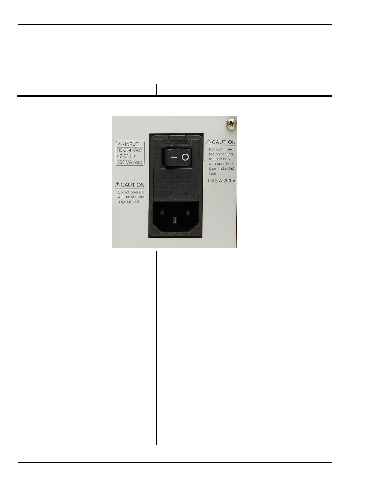
3-4 Rear Panel Ports and Connectors Front and Rear Panels
Rear Panel Port and Connector Descriptions
A summary of the VectorStar VNA rear panel connectors is available in Table 3-2 below. The table defines each
connector’s name, its connector type and general specifications. The External I/O Connector also provides a
connector pin-out diagram.
Table 3-2. VectorStar MS4640A Series VNA Rear Panel Connectors (1 of 10)
Connector Name Primary Function / Cross References
AC Power Connectors and Controls
AC Power Input Module
AC Power Rocker Switch
AC Power Internal Fuses Use the tab in the AC Power Rocker Switch (described
Contains the AC Power Rocker Switch, the AC Power
Internal Fuses (under the switch) and the IEC C14 Chassis
AC Power Socket, described in rows below.
Power On
Used to the turn the VNA on and off where “|” is ON and “O” is
OFF.
Standby to Operate Mode
Once turned on, the VNA is in standby mode. On the front
panel, press and hold the left side Standby/Operate key for at
least one (1) second to place the VNA in operate mode.
Operate to Standby Mode
With the VNA in operate mode, press and hold the
Standby/Operate key for at least one second to return the
VNA to standby mode.
Power Off
Only turn off the VNA when it is in standby mode. Do not
disconnect the AC power while the VNA is in operate mode. Do
not turn off the VNA while it is in operate mode.
above) to remove the fuse cover and access the fuses.
Two (2) T-Type 6.3 A 250 Volt internal fuses
Rated for 700 VA max.
90-264 VAC, 47-63 Hz (power factor controlled)
3-14 PN: 10410-00266 Rev: L MS4640A Series VNA OM
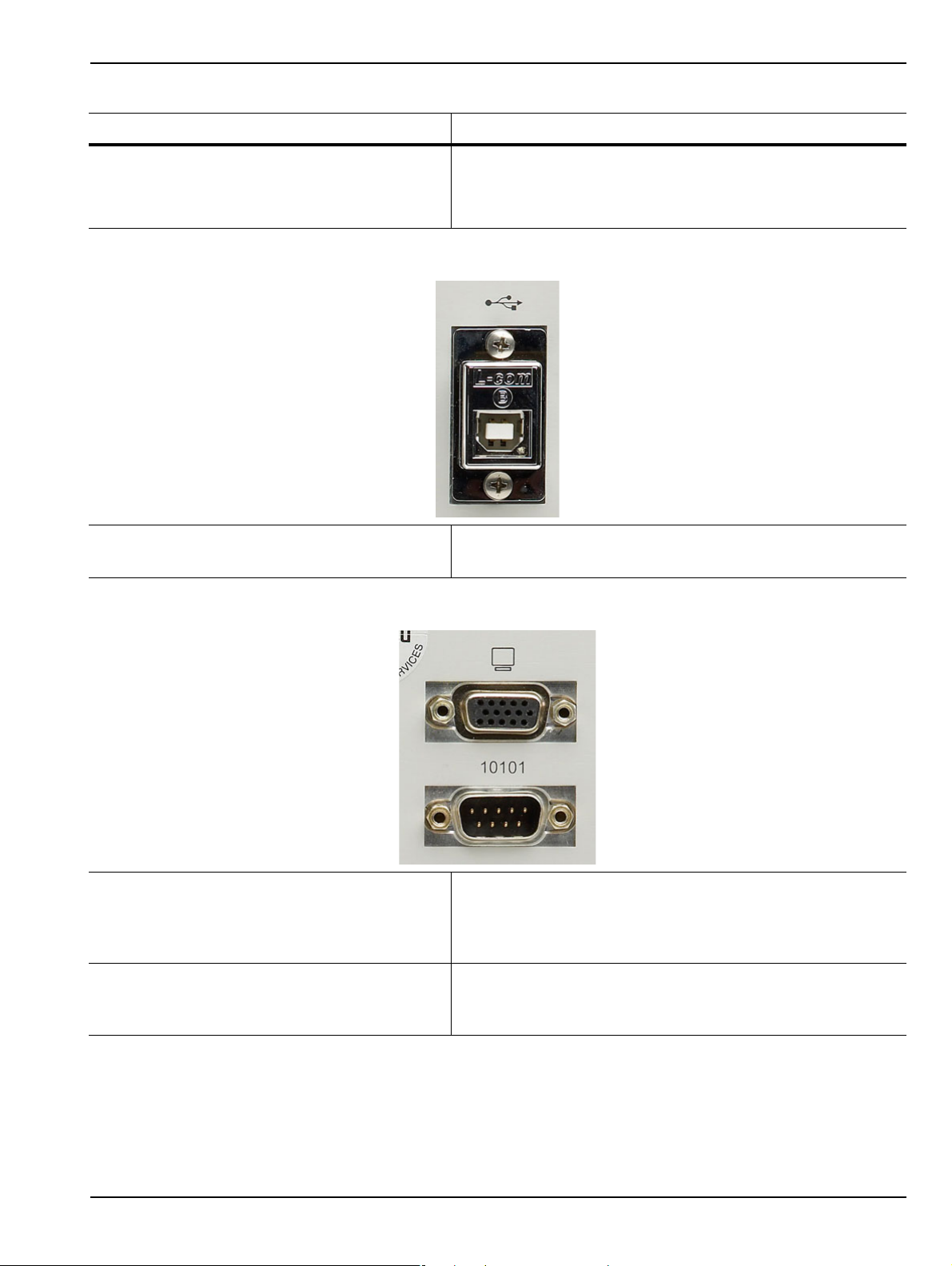
Front and Rear Panels 3-4 Rear Panel Ports and Connectors
Table 3-2. VectorStar MS4640A Series VNA Rear Panel Connectors (1 of 10)
Connector Name Primary Function / Cross References
IEC C14 Chassis AC Power Socket Allows for a cable connection to AC mains power using the IEC
C13 AC Line Socket on the provided power cord. The other
end of the provided power cord provides a plug suit able fo r the
instrument location.
USB Control Port
USB Control Port USB 2.0 Type B Port
controlling the instrument externally and for remote operation.
XGA/VGA and Serial (10101) Ports
XGA/VGA Video Port 15-pin Mini D-Sub (f) Connector
For simultaneously projecting the instrument’s screen display
onto an external VGA monitor, with minimum resolution of
1024 x 768.
Serial (10101) Port 9-pin Mini D-Sub (f) Connector
Compatible with RS-232C. Provides control for AutoCal
modules and other accessories.
MS4640A Series VNA OM PN: 10410-00266 Rev: L 3-15
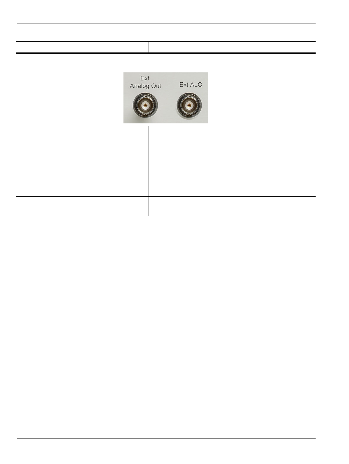
3-4 Rear Panel Ports and Connectors Front and Rear Panels
Table 3-2. VectorStar MS4640A Series VNA Rear Panel Connectors (1 of 10)
Connector Name Primary Function / Cross References
External Analog Out Ports
External (Ext) Analog Out BNC (f) Connector
External Analog Output. For external attenuator control,
external switch control, analog triggering assistance,
measurement system integration and other purposes.
Normal operating modes: Sawtooth sync sweep, TTL
indication of driving port, open loop level controller.
Range: -10 V to +10 V; low impedance drive.
Accuracy: 20 mV + 2%.
External (Ext) Automatic Level Control (ALC) BNC (f) Connector
External Automatic Level Control.
3-16 PN: 10410-00266 Rev: L MS4640A Series VNA OM
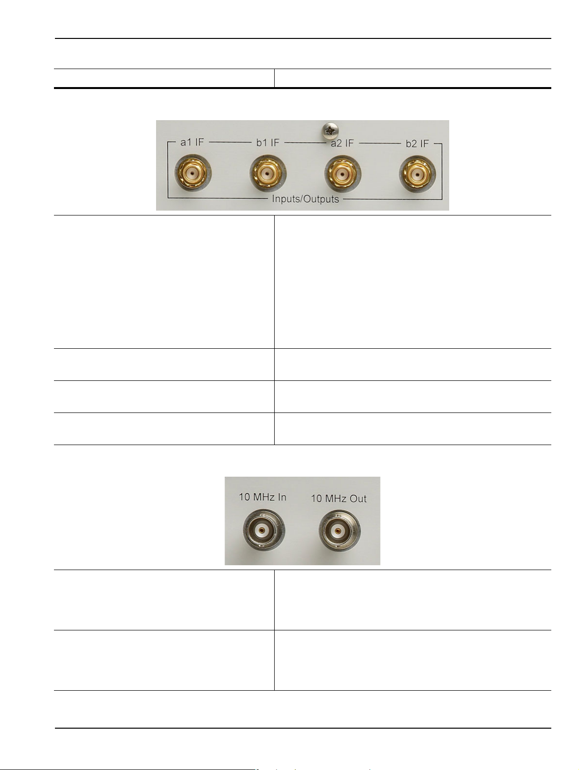
Front and Rear Panels 3-4 Rear Panel Ports and Connectors
Table 3-2. VectorStar MS4640A Series VNA Rear Panel Connectors (1 of 10)
Connector Name Primary Function / Cross References
IF Input/Output Loop Connectors
Input/Outputs a1 IF SMA (f) Connectors
Inputs used with external converters such as Millimeter Wave
(mmW) modules, or for antenna testing.
Outputs used with external IF digitizers and pr oc essors.
Nominal Inputs: 5 to 20 MHz (mode dependant), 0 dBm for full
scale Nominal.
Outputs: 0.2 to 100 MHz (mode dependant), +10 dBm max.
These ports also used to interface with the VectorStar
ME7828x Broadband/Millimeter Wave Systems.
Input/Outputs b1 IF SMA (f) Connectors
As above.
Input/Outputs a2 IF SMA (f) Connectors
As above.
Input/Outputs b2 IF SMA (f) Connectors
As above.
10 MHZ Input/Output Ports
10 MHz Input BNC (f) Connector
Auto-sensing, better than 0.001 Hz/Hz accuracy
recommended.
Signal: –10 dBm to +3 dBm, Nominal 50 Ohms.
10 MHz Output BNC (f) Connector
Derived from the internal reference time base, unless an
external 10 MHz reference input is applied.
0 ± 5 dBm sinusoidal, 50 Ohms
MS4640A Series VNA OM PN: 10410-00266 Rev: L 3-17

3-4 Rear Panel Ports and Connectors Front and Rear Panels
14
15
16
17
18
19
20
21
22
23
24
25
24681012
135791113
Table 3-2. VectorStar MS4640A Series VNA Rear Panel Connectors (1 of 10)
Connector Name Primary Function / Cross References
External I/O and GPIB Ports
s
External I/O Port 25-pin D-Sub (f) connector.
User-defined I/O for custom external test set interface, to
synchronize with different sweep states, such as S t art, S top, or
Driven Port. The next section provides a pin out diagram of the
connector.
External I/O Port Connector Pin Out
Pin Number Pin Name – Description
1 Limit Pass/Fail – Indicates the results of limit testing for all
channels. User selectable from the Limit Line setup menu.
(0 V to 3.3 V) TTL-high = Fail or TTL-low = Fail.
3-18 PN: 10410-00266 Rev: L MS4640A Series VNA OM

Front and Rear Panels 3-4 Rear Panel Ports and Connectors
Table 3-2. VectorStar MS4640A Series VNA Rear Panel Connectors (1 of 10)
Connector Name Primary Function / Cross References
2, 3, 15, 16 TTL In – Configurable as a digital input for use in sending
information to the instrument from external sensors or input
devices. The inputs are TTL compatible and 5 V tolerant .
4, 13, 14, 21 GND – Digital signaling ground.
5 - 12, 17-20, 22 TTL Out – Conf igu ra b l e as a dig ital output for use in sending
information to external devices, handlers, and outpu t
processors. The outputs are 0 V low and +3.3 V high and are
TTL compatible.
23 - 25 Reserved – Reserved for controlling Anritsu external test sets.
IEEE 488.2 GPIB Port 24-Pin (f) GPIB Connector
GPIB talker/listener port
IEEE 488.2 compatible, for controlling the instrument
externally, for remote operation.
Dedicated GPIB Port 24-Pin (f) GPIB Connector.
Dedicated GPIB controller port
For the control of external instruments such as power meters,
external test sets, or other GPIB compatible accessories.
External Trigger and Lock Ports
Ext Trigger BNC (f) Connector
External Trigger
MS4640A Series VNA OM PN: 10410-00266 Rev: L 3-19
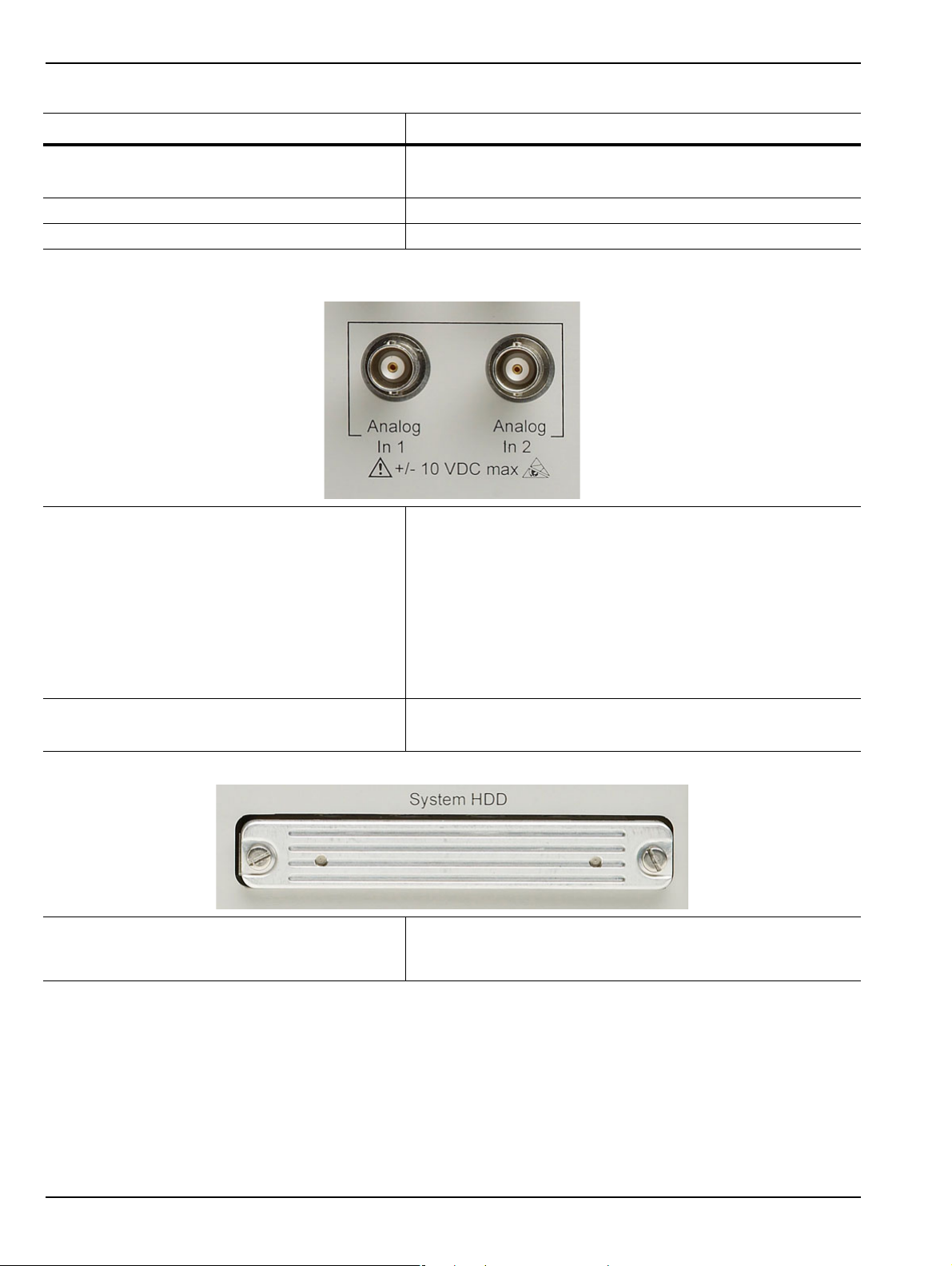
3-4 Rear Panel Ports and Connectors Front and Rear Panels
Table 3-2. VectorStar MS4640A Series VNA Rear Panel Connectors (1 of 10)
Connector Name Primary Function / Cross References
Lock Status BNC (f) Connector
Trigger Lock Status
Ready for Trigger BNC (f) Connector Trigger Out BNC (f) Connector
Analog In Ports
Analog Input 1 BNC (f) Connector
Independent input for measurements simultaneo us with the RF
measurements, for current sensing, efficiency computation,
and power detection.
Range: –10 V to +10 V with automatic offset and gain
calibrations.
Accuracy: 2 mV + 2% for |V| < 5 V; 2% for |V| > 5 V
Nominal input impedance: 60 K Ohms.
Analog Input 2 BNC (f) Connector
As above.
System Hard Disk Drive (HDD)
‘
System SSD/HDD The system removable Soid S t ate Drive (or Hard Disk Drive on
older VNAs). If spare drives are available, the SSD/HDD can
be quickly exchanged for security or other reasons.
3-20 PN: 10410-00266 Rev: L MS4640A Series VNA OM

Front and Rear Panels 3-4 Rear Panel Ports and Connectors
Table 3-2. VectorStar MS4640A Series VNA Rear Panel Connectors (1 of 10)
Connector Name Primary Function / Cross References
Network, USB, and PS2 Connectors
LAN Ethernet Port 10/100BaseT Ethernet RJ-45 Connector.
Standard.
Universal Series Bus (USB) 2.0 Type A Ports USB 2.0 Type A Ports, two (2) on Rear Panel.
For peripherals such as keyboard, mouse, memory stick, and
hardware key.
There are two additional USB 2.0 Type A Ports located on the
front panel.
Keyboard/Mouse PS/2 Ports Dedicated Mini-DIN PS/2 ports, two (2) on Rear Panel.
Used to connect a PS/2 keyboard and/or a PS/2 mouse.
With a user-supplied PS/2 to USB adapter, can be used to
connect a USB keyboard and USB mouse, sparing the
USB 2.0 ports for additional peripherals.
Bias Input Ports
Bias Input Port 1 Connector BNC (f) Connector.
One input per Bias Input Port
Optional. Equipped with Option 051, 061, or 062.
Bias Input Port 2 Connector BNC (f) Connector.
As above.
MS4640A Series VNA OM PN: 10410-00266 Rev: L 3-21
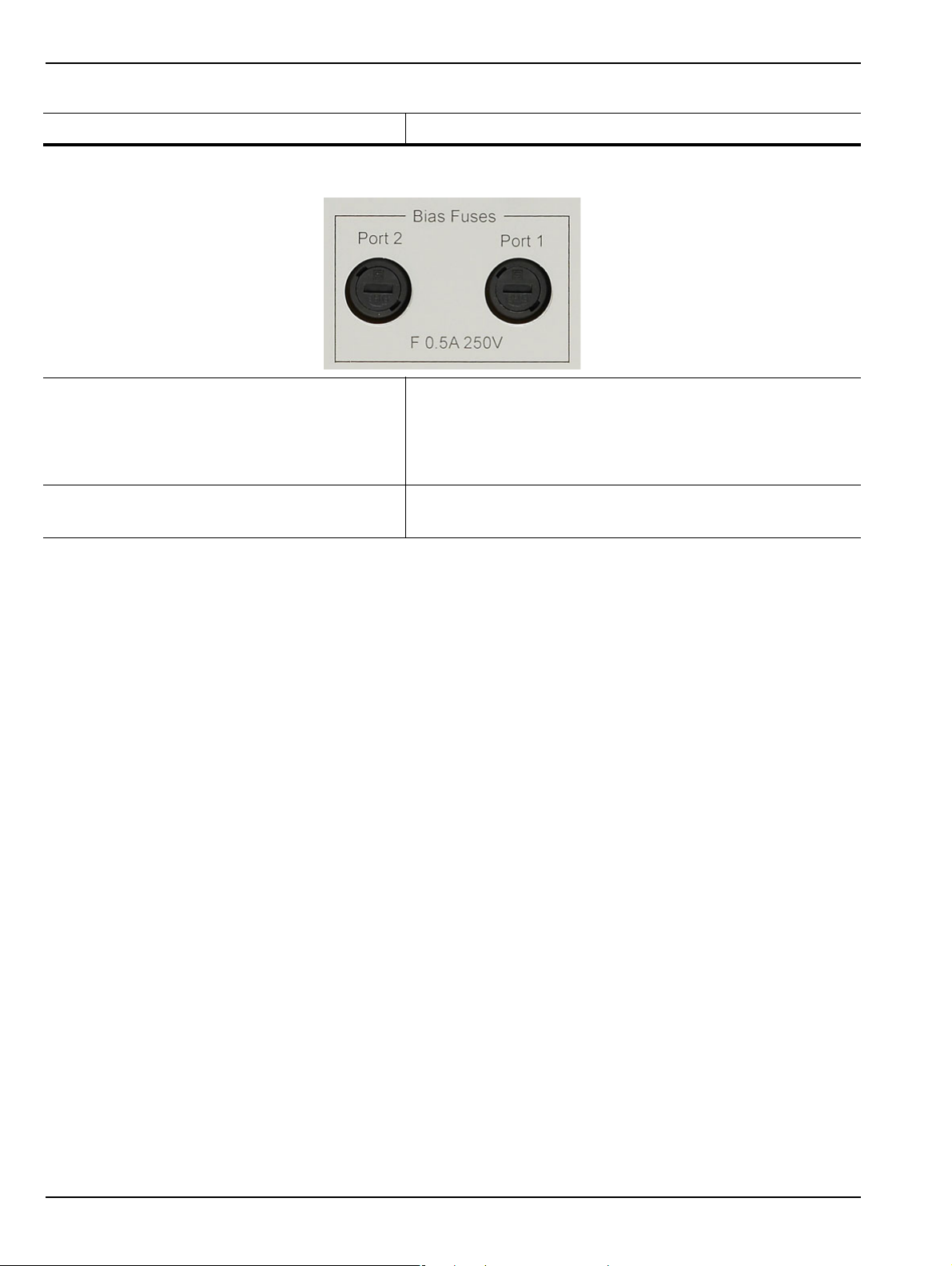
3-4 Rear Panel Ports and Connectors Front and Rear Panels
Table 3-2. VectorStar MS4640A Series VNA Rear Panel Connectors (1 of 10)
Connector Name Primary Function / Cross References
Bias Fuses
Bias Fuse Port 1 Fuse Connector
Included with optional Bias Input Ports above.
One fuse per Bias Input Port
Fuses are F-Type rated at 0.5 A, 250 V.
Bias Fuse Port 2 Fuse Connector
As above.
3-22 PN: 10410-00266 Rev: L MS4640A Series VNA OM
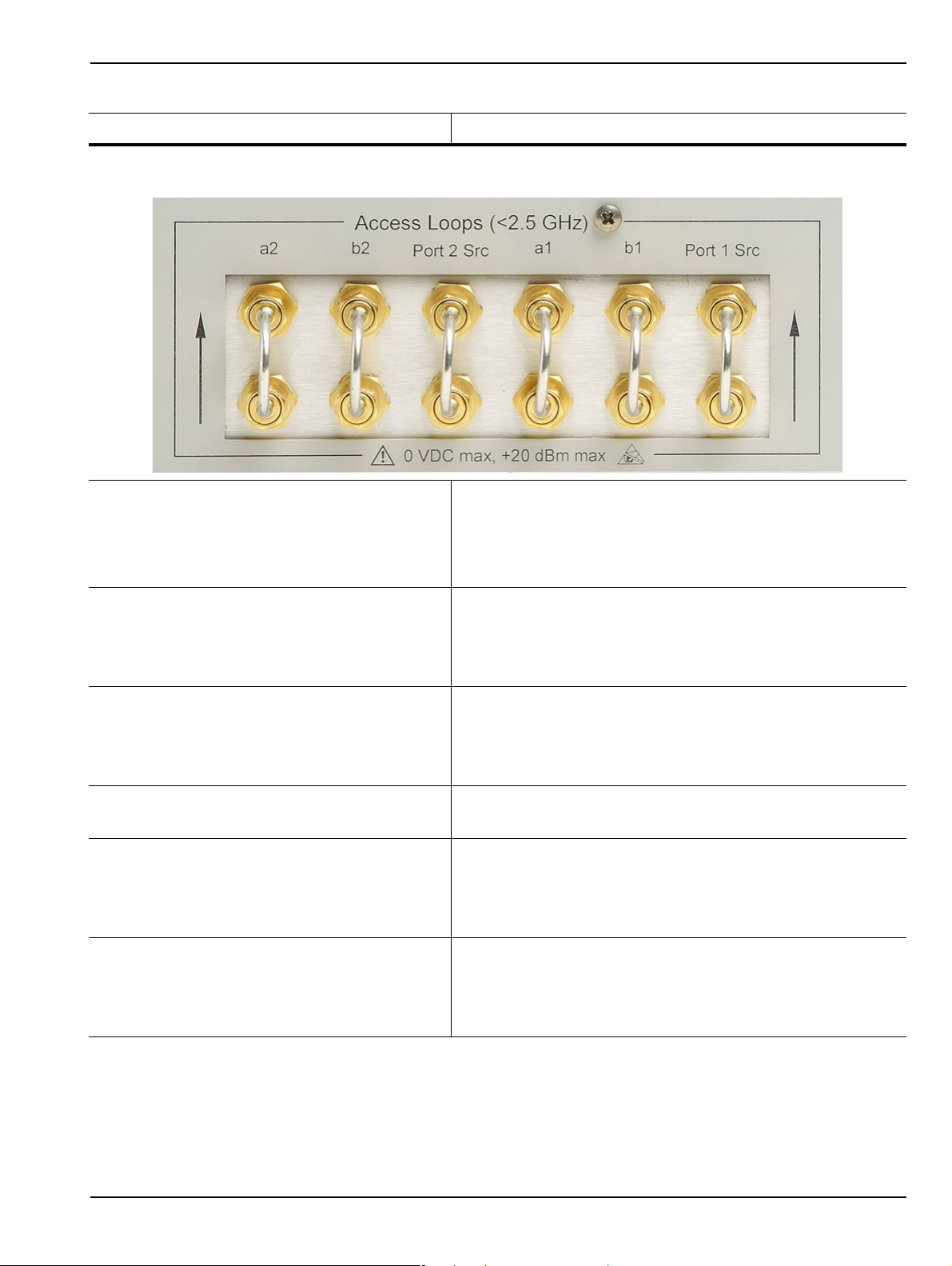
Front and Rear Panels 3-4 Rear Panel Ports and Connectors
Table 3-2. VectorStar MS4640A Series VNA Rear Panel Connectors (1 of 10)
Connector Name Primary Function / Cross References
Access Loops (< 2.5 GHz)
a2 Access Loop SMA (f) port with SMA (m) loop.
Receiver path for Port 2
For <2.5 GHz frequency coverage.
Damage Input Level: +20 dBm max., 0 VDC max.
b2 Access Loop SMA (f) port with SMA (m) loop.
Test receiver path for Port 2. Specifications as above.
Also used to connect with the VectorStar MN469xB 4-Port
(Multi-Port) Test Sets.
Port 2 Src Loop SMA (f) port with SMA (m) loop.
Port 2 Source path. Specifications as above.
Also used to connect with the VectorStar MN469xB 4-Port
(Multi-Port) Test Sets.
a1 Access Loop SMA (f) port with SMA (m) loop.
Receiver path for Port 1. Specifications as above.
b1 Access Loop SMA (f) port with SMA (m) loop.
Test receiver path for Port 1. Specifications as above.
Also used to connect with the VectorStar MN469xB 4-Port
(Multi-Port) Test Sets.
Port 1 Src Loop SMA (f) port with SMA (m) loop.
Port 1 Source path. Specifications as above.
Also used to connect with the VectorStar MN469xB 4-Port
(Multi-Port) Test Sets.
MS4640A Series VNA OM PN: 10410-00266 Rev: L 3-23

3-4 Rear Panel Ports and Connectors Front and Rear Panels
3-24 PN: 10410-00266 Rev: L MS4640A Series VNA OM
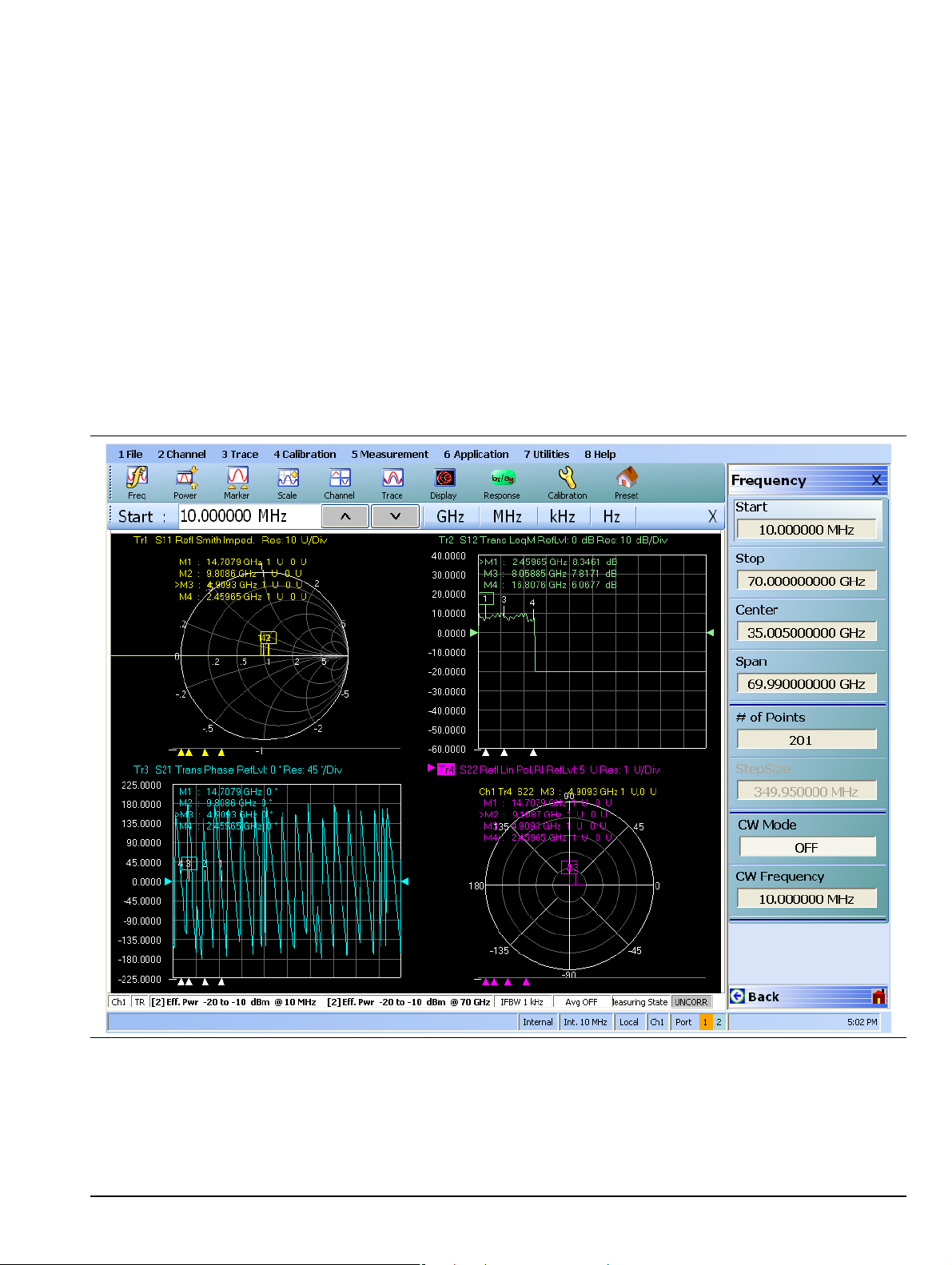
Chapter 4 — User Interface Display
4-1 Chapter Overview
The chapter describes the general display options of the MS4640A Series VNA and provides a general
description of the MENU BAR, the ICON TOOLBAR, and the right-side function menus. General descriptions
and procedures are provided for channel setup, trace graph setup, marker setup, and limit line setup. The
MS4640A Series VNA displays measurement data using a “Channel Concept” where each channel can display
both a different S-Parameter (or another specialty parameter) and a different graph type. As each channel is
selected, the previously selected trace graph types, scaling, reference delay, S-Parameter, and other
parameters associated with that channel appear on the screen. In addition, the same S-Parameter can be
displayed simultaneously on two or more channels using the same or different trace graph types.
4-2 User Interface Main Screen
Figure 4-1. User Interface - Single Channel - Four Traces
MS4640A Series VNA OM PN: 10410-00266 Rev: L 4-1

4-2 User Interface Main Screen User Interface Display
Single Channel User Interface Control and Display Areas
The entire instrument main display is a touch screen that can be manipulated by touching, or by clicking on
with an attached USB mouse. The figure below shows the general display areas for a single channel disp laying
four graphical traces.
When using the touch screen, a recommended best practice is to use a positive hard press to make
sure the required setting in input into the system. A light touch may not change the instrument setting
as required.
To recalibrate the touch screen, navigate to the CALIBRATE TOUCH SCREEN dialog box located at
Note
MAIN | System | SYSTEM | Utility | UTILITY | Calibrate Touch Screen | TOUCH SCREEN
CONTROL PANEL dialog box. The procedure is described in in the User Interface Manual –
10410-00307.
A detailed touch screen calibration and adjustment procedure is described in the VectorStar
MS4640A Series VNA Maintenance Manual – 10410-00268.
4-2 PN: 10410-00266 Rev: L MS4640A Series VNA OM

User Interface Display 4-2 User Interface Main Screen
1
2
3
4
11
6
5
9
10
7
8
Multiple Channel User Interface Control and Display Areas
Figure 4-2. User Interface Display Areas (1 of 2)
MS4640A Series VNA OM PN: 10410-00266 Rev: L 4-3

4-2 User Interface Main Screen User Interface Display
1. Menu Bar – Displays eight (8) drop-do wn menus: File,
Channel, Trace, Calibration, Measurement,
Application, Utilities, and Help.
2. Icon Toolbar – User-configured with up to 10 userselected quick access icons.
3. Field Toolbar – Appears only when field button is
clicked for input. Display field for value, with one or
more units (such as dB, dBm, or Hz), an Enter button,
and an X close button.
4. Display Area – Displays from one to 16 channels.
Each channel can have from one to 16 trace display
graphs. Each trace display can optionally have from
one to 12 markers, a reference marker, and an upper
and lower limit line.
5. Menu Title – Disp lays the name of th e displayed r igh tside menu. Menu titles are unique to each menu.
6. Menu Buttons – The menu buttons allow the user to
set parameters, make configuration selections, read
result values, start processes, toggle between two or
more values, display sub-menus, and display dialog
boxes.
Figure 4-2. User Interface Display Areas (2 of 2)
7. Menu Navigation Buttons – The navigation buttons
always appear at the bottom of the right-side menu
and allow browser-like forward and backward
navigation through the user’s history. Back returns to
previous selected higher-level menu, Next returns to
a previously selected lower-level menu), and Home
returns to the Main Menu.
8. System Status Bar – Displays status messages, and
configuration status that affects the entire instrument.
9. Channel Status Bar – Provides status for each
channel display near the bottom of the screen. If
multiple channels are displayed, there is a separate
status bar for each channel display.
10. Dialog Box Display Area – Most dialog boxes,
whether from the VNA or from the underlying
operating system, appear in the center of the display
area.
11.Tableau Data Display/Input Area – The tableau area
only appears when the appropriate menu button is
selected. When selected, the display shrinks upwards
and the tabular data area expands.
For all VectorStar VNA models, if the instrument is in 25,000 point mode, multiple channels can be selected by
the user.
4-4 PN: 10410-00266 Rev: L MS4640A Series VNA OM

User Interface Display 4-2 User Interface Main Screen
For VectorStar MS4640A Series VNAs, in 100,000 point mode, the instrument is limited to one channel. Each
available channel can have up to 16 graphical traces. The figure below shows an instrument setup with four
channels, each with four traces. The channel and trace display layout shown below is user-defined as a 2 × 2
configuration for channels and traces.
Four Channels — Each channel with Four Traces — 16 Total Traces
Figure 4-3. User Interface - 16 Traces
MS4640A Series VNA OM PN: 10410-00266 Rev: L 4-5

4-2 User Interface Main Screen User Interface Display
Function Access
The MS4640A Series VNA provides multiple methods to access the menus and functions that include:
• Front panel keys
• Attached USB mouse
• Attached USB keyboard
• Display touch screen
Each of the methods above can manipulate the instrument through the five major user interface areas on the
main display:
• The top MENU BAR with its drop-down menus and menu commands.
• The ICON TOOLBAR with up to 10 single-click functions, available as a default configuration or as a
user-definable configuration of icon fu n cti on s.
• The right side APPLICATION MENU system that provides access to over 100 function menus, sub-menus,
dialog boxes, and configuration options.
• For some parameters, selecting a button displays a FIELD TOOLBAR that appears just below the icon
toolbar allowing input of parameter values and units.
• For some parameters, selecting a button displays a CONFIGURATION or SETUP TABLEAU below the
main display area for input of complex parameter sets such as segmented frequency or power sweeps.
To Select a Channel
1. To select a channel in a multi-channel display, do one of the foll ow ing:
• Click anywhere inside the desired channel box.
• From the keyboard, ALT + 2 then 7 to view the previous channel or ALT + 2 then 8 to view the next
channel.
• On the top menu bar, select MENU BAR | Channel | Channel Prev or MENU BAR | Channel |
Channel Next.
• On the right side menu, select MAIN | Channel | CHANNEL | Chan Next or Chan Previous.
2. The selected channel border changes from gray to white. Above, Figure 4-3, “User Interface - 16 Traces”
on page 4-5 shows Channel 2 (Ch2) selected.
The Ch->Max, Ch->Next, and Ch-Prev icons are available for the icon toolba r. These icons provide
Note
To Maximize a Channel Display
1. Use one of the methods above to select the desired channel.
2. Do one of the following to maximize the selected channel:
3. The selected channel now fills the display area.
To Make the Display Area Larger
1. The top icon toolbar and the right side menus can be removed to make the display area larger.
2. Remove the icon toolbar by doing one of the following:
one click access to channel maximum, channel next, and channel previous functions. They can be
added to the icon toolbar for a custom configuration and saved as part of a preset configuration.
• From the keyboard, enter CTRL + 1 or ALT + 2, then 6.
• On the main display, double-click on the channel border box.
• On the top menu bar, select MENU BAR | Channel | Channel Max.
• On the right side menu, select MAIN | Channel | CHANNEL | Chan. Max.
• Maximize a channel display to review the channel status information at the bottom of its screen.
• From the keyboard, select ALT + 7 then 2
• On the top menu bar, select MENU BAR | Utilities | Toolbar Off.
4-6 PN: 10410-00266 Rev: L MS4640A Series VNA OM

User Interface Display 4-2 User Interface Main Screen
3. The icon toolbar disappears. Repeat Step #2 to make the icon toolbar re-appear.
4. Remove the right side menus by doing one of the following:
• From the keyboard, enter ALT + 7 then 7
• On the top menu bar, select MENU BAR | Utilities | Clear.
5. The right side menu disappears. Repeat Step #4 to make the menu re-appear.
To Select Traces within a Channel
1. Use one of the methods above to maximize the channel display.
2. To select a trace in a multi-trace display, do one of the following:
• With a mouse, single click the trace title.
• If you double-click either the trace title or anywhere within the trace, the trace is both
selected and maximized.
• From the keyboard, enter ALT + 3 then 7 to view the previous trace or ALT + 3 then 8 to view the
next trace.
• On the top menu bar, select MENU BAR | Trace | Trace Prev or MENU BAR | Trace | Trace Next.
• On the right side menu, select MAIN | Trace | TRACE | Trace Previous or Trace Next.
• The selected trace number is highlighted and a left arrow appears.
f
Trace 1 Selected Trace 1 Not Selected
Figure 4-4. Trace Selection Indicator
The Tr->Max, Tr->Next, and Tr->Previous icons are available for the icon toolbar. These icons
Note
provide one click access to trace maximum, trace next, and trace previous functions. They can be
added to the icon toolbar for a custom configuration and saved as part of a preset configuration.
To Maximize a Tr ace Display
1. Use one of the methods above to select the desired trace.
2. For a maximum display, make sure the trace’s channel is maximized.
3. Do one of the following to maximize the selected trace:
• From the keyboard, select ALT + 3, then 6.
• On the main display, double-click anywhere in the trace display.
• On the top menu bar, select MENU BAR | Trace | Trace Max.
• On the right side menu, select MAIN | Trace | TRACE | Trace Max.
4. The selected trace now fills the display area.
• Maximize a trace display to review the trace status information at the bottom of trace screen.
5. Repeat the actions above to return the trace to its normal size.
MS4640A Series VNA OM PN: 10410-00266 Rev: L 4-7

4-3 Using the Front Panel Keys User Interface Display
4-3 Using the Front Panel Keys
Most front panel keys go directly to a specific first-level menu or sub-menu function. See Chapter 3, “Front and
Rear Panels” for a detailed description of all front panel keys and ports.
Table 4-1. Front Panel Hard Key Summary
Key Name Primary Functions
Power Key Pressing the Power key toggles the VNA between Operate mode and Standby mode.
Before using this key, make sure the rear panel AC Power Input Connector Switch is
set to ON.
Calibration Key Pressing Calibration displays the user interface Calibration menu. Measurement Key Pressing Measurement displays the Measurement menu in the user interface display. Application Key Pressing Application displays the Application menu in the user interface display. System Key Pressing System displays the System menu in the user interface display. File Key Pressing File displays the File menu in the user interface display. Help Key Pressing Help displays the Help menu in the user interface display. Preset Key Returns the instrument to the last active configuration preset loaded. Frequency Key Pressing Frequency displays the Frequency menu in the user interface display. Power Key Pressing Power displays the Power menu in the user interface display. Sweep Key Pressing Sweep displays the Sweep menu in the user interface display. Average Key Pressing Avg displays the Averaging menu in the user interface display. Response Key Pressing Response displays the Response menu in the user interface display. Display Key Pressing Display displays the Display menu in the user interface display. Scale Key Pressing Scale displays the Scale menu in the user interface display. Marker Key Pressing Marker displays the Marker menu in the user interface display. Channel Key Pressing Channel displays the Channel menu in the user interface display. Trace Key Pressing Trace displays the Tr ace menu in the user interface display.
4-8 PN: 10410-00266 Rev: L MS4640A Series VNA OM

User Interface Display 4-4 Using the Menu Bar Interface
4-4 Using the Menu Bar Interface
Menu Bar Overview
The menu bar at the top of the screen provides eight drop-down menus for quick access to major VectorStar
VNA menu functions and dialogs. The configuration is fixed and not user-configurable. The figure below shows
all of the available MENU BAR functions and command menus.
Figure 4-5. MENU BAR Major Functions, Drop-Down Menus, and Commands (1 of 2)
MS4640A Series VNA OM PN: 10410-00266 Rev: L 4-9

4-4 Using the Menu Bar Interface User Interface Display
The appearance of the CHANNEL menu depends on the
instrument point mode.
For all VectorStar VNA models, if the instrument is in
25,000 point mode, the CHANNEL menu has eight
selections, as shown in the left CHANNEL menu.
Figure 4-5. MENU BAR Major Functions, Drop-Down Menus, and Commands (2 of 2)
For VectorStar VNA models, if the instrument is in
100,000 point mode, the CHANNEL menu has only four
selections, as shown in the right CHANNEL menu.
Menu Bar General Operation
The MENU BAR drop-down menus and commands can be accessed by clicking on the menu bar and required
command.
The keyboard can be used to enter the menu and/or command short cut, most of which use the ALT
(ALTERNATE) key. To access a menu from the keyboard, press and hold the ALT (ALTERNATE) key and the
number in front of the menu name.
• For example, ALT+1 opens the FILE menu.
• For example, ALT+7 opens the UTILITY menu.
To access most commands listed on the drop-down menus, follow the ALT + sequence with the menu command
number.
• For example, to access the Preset command on the UTILITIES menu, enter ALT+7, and then 5.
• For example, to access the right side SYSTEM menu, enter ALT+7m and then 1.
Some MENU BAR menu commands can also be accessed by using the keyboard Control (CTRL) key. Press and
hold the CTRL key and then the letter key.
• For example, to recall a previously saved setup, enter CTRL + O (letter O).
• For example, to print the current display screen, enter CTRL + P.
Menu Bar Drop-Down Menus and Commands
The menu bar appears at the top of the instrument display and provides direct access to system menus and
some button functions.
The table below summarizes all menu bar drop down commands and provides cross references to sections that
describe the resultant menu or command in greater detail.
Table 4-2. Menu Bar Drop-Down Menu Descriptions (1 of 12)
Menu and Command Name Menu and Command Descriptions
FILE Drop-Down Menu
• Keyboard: ALT + 1
• MENU BAR | File
• MAIN | File | FILE
4-10 PN: 10410-00266 Rev: L MS4640A Series VNA OM

User Interface Display 4-4 Using the Menu Bar Interface
Table 4-2. Menu Bar Drop-Down Menu Descriptions (2 of 12)
Menu and Command Name Menu and Command Descriptions
Recall Setup Command
Recall Data Command
Save Setup Command
Select displays the RECALL SETUP dialog box and allows the recall of previously
saved setup and/or calibration files:
– Active Channel Setup and Calibration (.chx) File
– Active Channel Setup (.stx) File
– All Channel Setup (.sta) File
• Keyboard: CTRL + O (letter O)
• MENU BAR | File | Recall Setup
• MAIN | File | FILE | Recall Setup | RECALL SETUP Dialog Box
Select displays the RECALL DA TA dialog box and allows the recall of a previously
saved active channel and/or active trace data file of these types:
– Active Channel S2P (.s2p) File
– Formatted Data into Active Trace (.tdf) File
– Unformatted Data into Active Trace (.tdu) File
– Formatted Data into Active Trace Memory (.tdf) File
– Unformatted Data into Active Trace Memory (.tdu) File
• Keyboard: Keyboard: ALT + O (letter O)
• MENU BAR | File | Recall Data
• MAIN | File | FILE | Recall Data | RECALL DATA Dialog Box
Select displays the Save Setup dialog box and allows the user to save the
currently applied system presets configuration file.
• Keyboard: CTRL + S
• MENU BAR | File | Save Setup
• MAIN | File | FILE | Save Setup | SAVE SETUP Dialog Box
Save Data Command Select displays the SAVE DATA (Active Channel .txt) dialog box. Use this dialog
to save the current channel data file.
• Keyboard: ALT + S
• MENU BAR | File | Save Data
• MAIN | File | FILE | Save Data | SAVE DATA Dialog Box
Print Command Select displays the Windows PRINT dialog box to print the current main display.
• Keyboard: CTRL + P
• MENU BAR | File | Print
• MAIN | File | Print | PRINT Dialog Box
Page Setup Command Select dispays the Windows PAGE SETUP dialog box with controls for:
• Paper size
• Paper source tray at printer
• Orientation as Portrait or Landscape
• Margins for Left, Right, Tol, and Bottom
MS4640A Series VNA OM PN: 10410-00266 Rev: L 4-11

4-4 Using the Menu Bar Interface User Interface Display
Table 4-2. Menu Bar Drop-Down Menu Descriptions (3 of 12)
Menu and Command Name Menu and Command Descriptions
Print Setup Command Select displays the PRINT SETUP dialog box. The controls allow the print output
to be customized as required. The following paramaters can be set:
• Output Format – Can be set as Bitmap with Page Setup, 4 Trace Graphical, or 4
Trace Tabular.
• Header Output – Include Header – The header configuration set in the fields
below can be included or left off print reports. Each field can be separately
configured to be included or not.
• Header Output – Model – Provides an input field for model number
information such as the DUT or VNA model.
• Header Output – Operator Name – Provides an input field for operator name
or other identification.
• Header Output – Device ID – Provides an input field for the DUT
identification.
• Header Output – Operator Comment – Provides a large free form input field
for comments about the DUT or test.
• Logo Setup – Include Logo – The logo set in th e fields below can be included or
left off print reports.
• Select Logo Type – Anritsu – The default selection set an Anritsu logo or
user defined logo in BMP graphics format.
• Select Logo Type – User – If a user logo is selected, the graphic file it must
be copied onto the VectorStar VNA in a known location. Then use the
Browse button to navigate to the logo file.
Exit Command Select displays a confirmation dialog box. Click OK to exit the VectorStar
application and return to the Windows OS desktop. Click Cancel to remain in the
VectorStar application.
• MENU BAR | File | Exit
4-12 PN: 10410-00266 Rev: L MS4640A Series VNA OM

User Interface Display 4-4 Using the Menu Bar Interface
Table 4-2. Menu Bar Drop-Down Menu Descriptions (4 of 12)
Menu and Command Name Menu and Command Descriptions
CHANNEL Drop-Down
Menu
• CHANNEL menu for 25,000 point mode shown at left.
• CHANNEL menu for 100,000 point mode short at right.
• Keyboard: ALT + 2
• MENU BAR | Channel
Frequency
Power
Sweep
Averaging
• MAIN | Channel | CHANNEL
Select displays the right-side FREQUENCY menu.
• Front Panel Key: Frequency
• Keyboard: ALT + 2 then 1
• MENU BAR | Channel | Frequency
• MAIN | Frequency | FREQUENCY
Select displays the right-side POWER menu.
• Front Panel Key: Power
• Keyboard: ALT + 2 then 2
• MENU BAR | Channel | Power
• MAIN | Power | POWER
Select displays the right-side SWEEP SETUP menu.
• Front Panel Key: Sweep
• Keyboard: ALT + 2, then 3
• MENU BAR | Channel | Sweep
• MAIN | Sweep Setup | SWEEP SETUP
Select displays the right-side AVERAGING menu.
• Front Panel Key: Avg (Average)
• Keyboard: ALT + 2 then 4
• MENU BAR | Channel | Averaging
• MAIN | Averaging | ADVERAGING
MS4640A Series VNA OM PN: 10410-00266 Rev: L 4-13

4-4 Using the Menu Bar Interface User Interface Display
Table 4-2. Menu Bar Drop-Down Menu Descriptions (5 of 12)
Menu and Command Name Menu and Command Descriptions
Channel Menu Command Select displays the right-side CHANNEL menu.
• Prerequisites: Instrument must be in 25,000 point mode.
• Front Panel: Channel Key
• Keyboard: ALT + 2, then 5
• MENU BAR | Channel | Channel Menu
• MAIN | Channel | CHANNEL
Channel Max Command
Channel Previous Command
Select maximizes the display of the active channel. Select again returns to the
previous multi-channel display.
• Prerequisites: Instrument must be in 25,000 point mode.
• Keyboard: ALT + 2, then 6
• Keyboard: CTRL + 1
• MENU BAR | Channel | Channel Max
• MAIN | Channel | CHANNEL | Chan. Max
Selects the next lower channel number. If channel 1 was previously selected,
selects the highest numbered channel.
• Prerequisites: Instrument must be in 25,000 point mode.
Channel Next Command
TRACE Drop-Down
Menu
• Keyboard: ALT + 2, then 7
• MENU BAR | Channel | Channel Prev.
• MAIN | Channel | CHANNEL | Chan. Previous
Selects the next higher channel number. If the highest numbered channel was
previously selected, selects channel 1.
• Prerequisites: Instrument must be in 25,000 point mode.
• Keyboard: ALT + 2, then 8
• MENU BAR | Channel | Channel Next
• MAIN | Channel | CHANNEL | Chan. Next
• Keyboard: ALT + 3
• MENU BAR | Trace
• MAIN | Trace | TRACE
4-14 PN: 10410-00266 Rev: L MS4640A Series VNA OM
 Loading...