


MT8213E
Table of contents
 Loading...
User Guide
Cell Master
MT8212E and MT8213E
MT8212E
2 MHz to 4 GHz Cable and Antenna Analyzer
9 kHz to 4 GHz Spectrum Analyzer
10 MHz to 4 GHz Power Meter
MT8213E
2 MHz to 6 GHz Cable and Antenna Analyzer
9 kHz to 6 GHz Spectrum Analyzer
10 MHz to 6 GHz Power Meter
Appendix A provides a list of supplemental documentation for the
Cell Master features and options. The documentation set is
available as PDF files on the Anritsu website.
Anritsu Company
490 Jarvis Drive
Morgan Hill, CA 95037-2809
USA
http://www.anritsu.com
Part Number: 10580-00250
Revision: AA
Published: April 2020
Copyright 2020 Anritsu Company, USA. All Rights Reserved.


Cell Master UG PN: 10580-00250 Rev. AA Contents-1
Table of Contents
Chapter 1—General Information
1-1 Introduction . . . . . . . . . . . . . . . . . . . . . . . . . . . . . . . . . . . . . . . . . . . . . . . . . 1-1
Additional Documentation . . . . . . . . . . . . . . . . . . . . . . . . . . . . . . . . . . . 1-1
Contacting Anritsu for Sales and Service . . . . . . . . . . . . . . . . . . . . . . . 1-3
1-2 Instrument Description . . . . . . . . . . . . . . . . . . . . . . . . . . . . . . . . . . . . . . . . 1-3
1-3 Available Models. . . . . . . . . . . . . . . . . . . . . . . . . . . . . . . . . . . . . . . . . . . . . 1-4
1-4 Available Options . . . . . . . . . . . . . . . . . . . . . . . . . . . . . . . . . . . . . . . . . . . . 1-4
1-5 Calibration and Verification. . . . . . . . . . . . . . . . . . . . . . . . . . . . . . . . . . . . . 1-5
1-6 Instrument Care and Preventive Maintenance . . . . . . . . . . . . . . . . . . . . . . 1-6
Connector Care . . . . . . . . . . . . . . . . . . . . . . . . . . . . . . . . . . . . . . . . . . . 1-6
ESD Caution . . . . . . . . . . . . . . . . . . . . . . . . . . . . . . . . . . . . . . . . . . . . . 1-7
RF Input Warning . . . . . . . . . . . . . . . . . . . . . . . . . . . . . . . . . . . . . . . . . 1-7
Battery Replacement . . . . . . . . . . . . . . . . . . . . . . . . . . . . . . . . . . . . . . . 1-7
1-7 Secure Environment Workplace . . . . . . . . . . . . . . . . . . . . . . . . . . . . . . . . . 1-9
Cell Master Memory Types . . . . . . . . . . . . . . . . . . . . . . . . . . . . . . . . . . 1-9
Erase All User Files in Internal Memory . . . . . . . . . . . . . . . . . . . . . . . . 1-9
Recommended Usage in a Secure Environment . . . . . . . . . . . . . . . . 1-10
Chapter 2—Instrument Overview
2-1 Introduction . . . . . . . . . . . . . . . . . . . . . . . . . . . . . . . . . . . . . . . . . . . . . . . . . 2-1
2-2 Turning On the Cell Master. . . . . . . . . . . . . . . . . . . . . . . . . . . . . . . . . . . . . 2-1
2-3 Instrument Front Panel . . . . . . . . . . . . . . . . . . . . . . . . . . . . . . . . . . . . . . . . 2-2
LED Indicators . . . . . . . . . . . . . . . . . . . . . . . . . . . . . . . . . . . . . . . . . . . . 2-3
Front Panel Keys . . . . . . . . . . . . . . . . . . . . . . . . . . . . . . . . . . . . . . . . . . 2-3
2-4 Interface Screen . . . . . . . . . . . . . . . . . . . . . . . . . . . . . . . . . . . . . . . . . . . . . 2-6
Touch Screen Keys . . . . . . . . . . . . . . . . . . . . . . . . . . . . . . . . . . . . . . . . 2-8
Symbols and Icons on the Title Bar . . . . . . . . . . . . . . . . . . . . . . . . . . . 2-8
Symbols and Indicators . . . . . . . . . . . . . . . . . . . . . . . . . . . . . . . . . . . . . 2-9
Display Settings. . . . . . . . . . . . . . . . . . . . . . . . . . . . . . . . . . . . . . . . . . 2-10
Touch Screen Calibration . . . . . . . . . . . . . . . . . . . . . . . . . . . . . . . . . . 2-11
Calibration Symbols. . . . . . . . . . . . . . . . . . . . . . . . . . . . . . . . . . . . . . . 2-13
2-5 Data Entry. . . . . . . . . . . . . . . . . . . . . . . . . . . . . . . . . . . . . . . . . . . . . . . . . 2-14
Numeric Values . . . . . . . . . . . . . . . . . . . . . . . . . . . . . . . . . . . . . . . . . . 2-14
Selection Lists . . . . . . . . . . . . . . . . . . . . . . . . . . . . . . . . . . . . . . . . . . . 2-14
Text Entry . . . . . . . . . . . . . . . . . . . . . . . . . . . . . . . . . . . . . . . . . . . . . . 2-15
2-6 Mode Selector. . . . . . . . . . . . . . . . . . . . . . . . . . . . . . . . . . . . . . . . . . . . . . 2-16
2-7 Connector Panel . . . . . . . . . . . . . . . . . . . . . . . . . . . . . . . . . . . . . . . . . . . . 2-17

Contents-2 PN: 10580-00250 Rev. AA Cell Master UG
Table of Contents (Continued)
2-8 Soft Carrying Case . . . . . . . . . . . . . . . . . . . . . . . . . . . . . . . . . . . . . . . . . . 2-21
2-9 Tilt Bail Stand . . . . . . . . . . . . . . . . . . . . . . . . . . . . . . . . . . . . . . . . . . . . . . 2-22
Chapter 3—Quick Start Guide
3-1 Introduction . . . . . . . . . . . . . . . . . . . . . . . . . . . . . . . . . . . . . . . . . . . . . . . . . 3-1
3-2 Measurement Mode Selection . . . . . . . . . . . . . . . . . . . . . . . . . . . . . . . . . . 3-1
3-3 Cable & Antenna Analyzer . . . . . . . . . . . . . . . . . . . . . . . . . . . . . . . . . . . . . 3-2
Select the Measurement Type. . . . . . . . . . . . . . . . . . . . . . . . . . . . . . . . 3-2
Set the Frequency . . . . . . . . . . . . . . . . . . . . . . . . . . . . . . . . . . . . . . . . . 3-2
Set the Amplitude . . . . . . . . . . . . . . . . . . . . . . . . . . . . . . . . . . . . . . . . . 3-2
Turn on Markers . . . . . . . . . . . . . . . . . . . . . . . . . . . . . . . . . . . . . . . . . . 3-3
Single Limit Line . . . . . . . . . . . . . . . . . . . . . . . . . . . . . . . . . . . . . . . . . . 3-4
DTF Setup . . . . . . . . . . . . . . . . . . . . . . . . . . . . . . . . . . . . . . . . . . . . . . . 3-5
Calibrate with OSL Calibration . . . . . . . . . . . . . . . . . . . . . . . . . . . . . . . 3-6
3-4 Spectrum Analyzer . . . . . . . . . . . . . . . . . . . . . . . . . . . . . . . . . . . . . . . . . . . 3-8
Set Start and Stop Frequencies. . . . . . . . . . . . . . . . . . . . . . . . . . . . . . . 3-8
Enter the Center Frequency . . . . . . . . . . . . . . . . . . . . . . . . . . . . . . . . . 3-8
Select a Signal Standard . . . . . . . . . . . . . . . . . . . . . . . . . . . . . . . . . . . . 3-8
Set the Measurement Frequency Bandwidth. . . . . . . . . . . . . . . . . . . . . 3-8
Set the Amplitude . . . . . . . . . . . . . . . . . . . . . . . . . . . . . . . . . . . . . . . . . 3-9
Power Offset Set Up for Compensating External Loss . . . . . . . . . . . . . 3-9
Set the Span . . . . . . . . . . . . . . . . . . . . . . . . . . . . . . . . . . . . . . . . . . . . . 3-9
Single Limit Line . . . . . . . . . . . . . . . . . . . . . . . . . . . . . . . . . . . . . . . . . 3-10
Create a Limit Envelope . . . . . . . . . . . . . . . . . . . . . . . . . . . . . . . . . . . 3-10
Setting Up Markers . . . . . . . . . . . . . . . . . . . . . . . . . . . . . . . . . . . . . . . 3-11
Select a Measurement Type . . . . . . . . . . . . . . . . . . . . . . . . . . . . . . . . 3-12
External Power On. . . . . . . . . . . . . . . . . . . . . . . . . . . . . . . . . . . . . . . . 3-12
Chapter 4— File Management
4-1 Introduction . . . . . . . . . . . . . . . . . . . . . . . . . . . . . . . . . . . . . . . . . . . . . . . . . 4-1
4-2 Managing Files . . . . . . . . . . . . . . . . . . . . . . . . . . . . . . . . . . . . . . . . . . . . . . 4-1
File Types . . . . . . . . . . . . . . . . . . . . . . . . . . . . . . . . . . . . . . . . . . . . . . . 4-1
Save Files . . . . . . . . . . . . . . . . . . . . . . . . . . . . . . . . . . . . . . . . . . . . . . . 4-2
Recall Files . . . . . . . . . . . . . . . . . . . . . . . . . . . . . . . . . . . . . . . . . . . . . . 4-6
Copy Files . . . . . . . . . . . . . . . . . . . . . . . . . . . . . . . . . . . . . . . . . . . . . . . 4-7
Delete Files . . . . . . . . . . . . . . . . . . . . . . . . . . . . . . . . . . . . . . . . . . . . . . 4-8
4-3 File Menu Overview . . . . . . . . . . . . . . . . . . . . . . . . . . . . . . . . . . . . . . . . . . 4-9

Cell Master UG PN: 10580-00250 Rev. AA Contents-3
Table of Contents (Continued)
4-4 File Menu . . . . . . . . . . . . . . . . . . . . . . . . . . . . . . . . . . . . . . . . . . . . . . . . . 4-10
Save Menu . . . . . . . . . . . . . . . . . . . . . . . . . . . . . . . . . . . . . . . . . . . . . 4-11
File Type Menu . . . . . . . . . . . . . . . . . . . . . . . . . . . . . . . . . . . . . . . . . . 4-12
Save Location Menu . . . . . . . . . . . . . . . . . . . . . . . . . . . . . . . . . . . . . . 4-12
Save On... Menu . . . . . . . . . . . . . . . . . . . . . . . . . . . . . . . . . . . . . . . . 4-13
Recall Menu . . . . . . . . . . . . . . . . . . . . . . . . . . . . . . . . . . . . . . . . . . . . 4-14
Copy Menu . . . . . . . . . . . . . . . . . . . . . . . . . . . . . . . . . . . . . . . . . . . . . 4-15
Delete Menu . . . . . . . . . . . . . . . . . . . . . . . . . . . . . . . . . . . . . . . . . . . 4-16
Chapter 5—System Operations
5-1 Introduction . . . . . . . . . . . . . . . . . . . . . . . . . . . . . . . . . . . . . . . . . . . . . . . . . 5-1
5-2 System Menu Overview . . . . . . . . . . . . . . . . . . . . . . . . . . . . . . . . . . . . . . . 5-2
5-3 System Menu . . . . . . . . . . . . . . . . . . . . . . . . . . . . . . . . . . . . . . . . . . . . . . . 5-3
System Options Menu . . . . . . . . . . . . . . . . . . . . . . . . . . . . . . . . . . . . . 5-4
System Options 2/2 Menu . . . . . . . . . . . . . . . . . . . . . . . . . . . . . . . . . 5-5
Power-On Menu . . . . . . . . . . . . . . . . . . . . . . . . . . . . . . . . . . . . . . . . . . 5-6
Display Settings Menu. . . . . . . . . . . . . . . . . . . . . . . . . . . . . . . . . . . . . . 5-7
Brightness Settings Menu . . . . . . . . . . . . . . . . . . . . . . . . . . . . . . . . . . . 5-8
Reset Menu . . . . . . . . . . . . . . . . . . . . . . . . . . . . . . . . . . . . . . . . . . . . . 5-9
5-4 Preset Menu . . . . . . . . . . . . . . . . . . . . . . . . . . . . . . . . . . . . . . . . . . . . . . . 5-10
5-5 Self Test . . . . . . . . . . . . . . . . . . . . . . . . . . . . . . . . . . . . . . . . . . . . . . . . . . 5-10
5-6 Firmware Update . . . . . . . . . . . . . . . . . . . . . . . . . . . . . . . . . . . . . . . . . . . 5-11
Chapter 6—GPS (Option 31)
6-1 Introduction . . . . . . . . . . . . . . . . . . . . . . . . . . . . . . . . . . . . . . . . . . . . . . . . . 6-1
6-2 Activating the GPS Feature . . . . . . . . . . . . . . . . . . . . . . . . . . . . . . . . . . . . 6-1
6-3 Resetting GPS . . . . . . . . . . . . . . . . . . . . . . . . . . . . . . . . . . . . . . . . . . . . . . 6-3
6-4 Saving and Recalling Traces with GPS Information . . . . . . . . . . . . . . . . . . 6-3
Saving Traces with GPS Information. . . . . . . . . . . . . . . . . . . . . . . . . . . 6-3
Recalling GPS Information . . . . . . . . . . . . . . . . . . . . . . . . . . . . . . . . . . 6-3
6-5 GPS Menu . . . . . . . . . . . . . . . . . . . . . . . . . . . . . . . . . . . . . . . . . . . . . . . . . 6-4
Chapter 7—Bias Tee (Option 10)
7-1 Overview. . . . . . . . . . . . . . . . . . . . . . . . . . . . . . . . . . . . . . . . . . . . . . . . . . . 7-1
Chapter 8—Anritsu Tool Box
8-1 Introduction . . . . . . . . . . . . . . . . . . . . . . . . . . . . . . . . . . . . . . . . . . . . . . . . . 8-1
8-2 Software Installation . . . . . . . . . . . . . . . . . . . . . . . . . . . . . . . . . . . . . . . . . . 8-1
8-3 Anritsu Software Tool Box . . . . . . . . . . . . . . . . . . . . . . . . . . . . . . . . . . . . . 8-2

Contents-4 PN: 10580-00250 Rev. AA Cell Master UG
Table of Contents (Continued)
8-4 Software Tools . . . . . . . . . . . . . . . . . . . . . . . . . . . . . . . . . . . . . . . . . . . . . . 8-3
Line Sweep Tools (LST) . . . . . . . . . . . . . . . . . . . . . . . . . . . . . . . . . . . . 8-3
Master Software Tools (MST) . . . . . . . . . . . . . . . . . . . . . . . . . . . . . . . . 8-3
easyTest Tools . . . . . . . . . . . . . . . . . . . . . . . . . . . . . . . . . . . . . . . . . . . 8-4
easyMap Tools . . . . . . . . . . . . . . . . . . . . . . . . . . . . . . . . . . . . . . . . . . . 8-4
Wireless Remote Tools . . . . . . . . . . . . . . . . . . . . . . . . . . . . . . . . . . . . . 8-4
Chapter 9—Web Remote Control
9-1 Introduction . . . . . . . . . . . . . . . . . . . . . . . . . . . . . . . . . . . . . . . . . . . . . . . . . 9-1
9-2 Setup . . . . . . . . . . . . . . . . . . . . . . . . . . . . . . . . . . . . . . . . . . . . . . . . . . . . . 9-1
LAN Connection. . . . . . . . . . . . . . . . . . . . . . . . . . . . . . . . . . . . . . . . . . . 9-1
Connection to a Wireless Router . . . . . . . . . . . . . . . . . . . . . . . . . . . . . . 9-2
9-3 Web Remote Control Interface . . . . . . . . . . . . . . . . . . . . . . . . . . . . . . . . . . 9-3
User Login . . . . . . . . . . . . . . . . . . . . . . . . . . . . . . . . . . . . . . . . . . . . . . . 9-3
Home Page . . . . . . . . . . . . . . . . . . . . . . . . . . . . . . . . . . . . . . . . . . . . . . 9-4
Remote Control . . . . . . . . . . . . . . . . . . . . . . . . . . . . . . . . . . . . . . . . . . . 9-5
Capture Screen . . . . . . . . . . . . . . . . . . . . . . . . . . . . . . . . . . . . . . . . . . . 9-7
Capture Trace . . . . . . . . . . . . . . . . . . . . . . . . . . . . . . . . . . . . . . . . . . . . 9-7
File List . . . . . . . . . . . . . . . . . . . . . . . . . . . . . . . . . . . . . . . . . . . . . . . . . 9-8
Device Management (not as Administrator) . . . . . . . . . . . . . . . . . . . . . 9-8
Device Management (Administrator) . . . . . . . . . . . . . . . . . . . . . . . . . 9-10
Logout . . . . . . . . . . . . . . . . . . . . . . . . . . . . . . . . . . . . . . . . . . . . . . . . . 9-12
Appendix A—Measurement Guides
A-1 Introduction . . . . . . . . . . . . . . . . . . . . . . . . . . . . . . . . . . . . . . . . . . . . . . . . A-1
Appendix B—LAN and DHCP
B-1 Introduction . . . . . . . . . . . . . . . . . . . . . . . . . . . . . . . . . . . . . . . . . . . . . . . . B-1
B-2 LAN Connection . . . . . . . . . . . . . . . . . . . . . . . . . . . . . . . . . . . . . . . . . . . . . B-1
B-3 Ethernet Configuration . . . . . . . . . . . . . . . . . . . . . . . . . . . . . . . . . . . . . . . . B-1
Ethernet Menu . . . . . . . . . . . . . . . . . . . . . . . . . . . . . . . . . . . . . . . . . . . B-2
DHCP . . . . . . . . . . . . . . . . . . . . . . . . . . . . . . . . . . . . . . . . . . . . . . . . . . B-4
B-4 ipconfig Tool . . . . . . . . . . . . . . . . . . . . . . . . . . . . . . . . . . . . . . . . . . . . . . . . B-5
B-5 Ping Tool . . . . . . . . . . . . . . . . . . . . . . . . . . . . . . . . . . . . . . . . . . . . . . . . . . B-6
Appendix C—Glossary of Terms
C-1 Introduction. . . . . . . . . . . . . . . . . . . . . . . . . . . . . . . . . . . . . . . . . . . . . . . . .C-1
C-2 Glossary . . . . . . . . . . . . . . . . . . . . . . . . . . . . . . . . . . . . . . . . . . . . . . . . . . . C-1
Index

Cell Master UG PN: 10580-00250 Rev. AA 1-1
Chapter 1 — General Information
1-1 Introduction
The Cell Master User Guide is part of a set of manuals that describe all of the instrument
functions and their use. This manual covers the instrument overview, system functions and
other common features, along with a brief guide to basic measurement concepts and setups.
Instrument operations are explained in various document types as listed below.
Additional Documentation
Document Part Number Description (Required Option)
10100-00065 Important Product Information, Compliance, and Safety Notices
10580-00215
ODTF-1 Optical Distance-to-Fault User Guide
ODTF-1 Optical Distance-to-Fault Module
10580-00349
Spectrum Analyzer Measurement Guide
Spectrum Analyzer
PIM Hunting
Interference Analyzer (Option 25)
Channel Scanner (Option 27)
C/W Signal Generator (Option 28)
Gated Sweep (Option 90)
Coverage Mapping (Option 431)
EMF Measurements (Option 444)
10580-00234
3GPP Signal Analyzer Measurement Guide
GSM/GPRS/EDGE Measurements (Option 880)
* GSM/EDGE RF Measurements (Option 40)
* GSM/EDGE Demodulation (Option 41)
W-CDMA/HSPA+ Measurements (Option 881)
* W-CDMA/HSPA+ RF Measurements (Option 44)
* W-CDMA/HSPA+ Demodulation (Option 65)
* W-CDMA/HSPA+ Over-the-Air Measurements (Option 35)
TD-SCDMA/HSPA+ Measurements (Option 882)
* TD-SCDMA/HSPA+ Measurements (Option 60)
* TD-SCDMA/HSPA+ Demodulation (Option 61)
* TD-SCDMA/HSPA+ Over-the-Air Measurements (Option 38)
LTE/LTE-A FDD/TDD Measurements (Option 883)
LTE and TD-LTE Coverage Mapping (included)
TD-LTE/LTE OTA EMF Measurements (Option 444)
* TD-LTE/LTE-A RF Measurements (Option 551)
* TD-LTE/LTE-A Modulation Measurements (Option 552)
* TD-LTE/LTE-A Over-the-Air Measurements (Option 556)
LTE 256QAM Demodulation Measurements (Option 886)
NB-IoT Measurements (Option 887)

1-1 Introduction General Information
1-2 PN: 10580-00250 Rev. AA Cell Master UG
* Indicates the option is obsolete.
10580-00235
3GPP2 Signal Analyzer Measurement Guide
CDMA/EV-DO Measurements (Option 884)
* CDMA RF Measurements (Option 42)
* CDMA Demodulation (Option 43)
* CDMA Over-the-Air Measurements (Option 33)
* EV-DO RF Measurements (Option 62)
* EV-DO Demodulation (Option 63)
* EV-DO Over-the-Air Measurements (Option 34)
10580-00236
WiMAX Signal Analyzer Measurement Guide
WiMAX Fixed/Mobile Measurements (Option 885)
* Fixed WiMAX RF Measurements (Option 46)
* Fixed WiMAX Demodulation (Option 47)
* Mobile WiMAX RF Measurements (Option 66)
* Mobile WiMAX Demodulation (Option 67)
* Mobile WiMAX Over-the-Air Measurements (Option 37)
10580-00237
Digital Video Broadcast Signal Analyzer Measurement Guide
ISDB-T Digital Video Measurements (Option 30)
ISDB-T SFN Measurements (Option 32)
ISDB-T BER Measurements (Option 79)
DVB-T/H Digital Video Measurements (Option 64)
DVB-T/H SFN Measurements (Option 78)
DVB-T/H BER Measurements (Option 57)
10580-00238
Backhaul Analyzer Measurement Guide
* T1 Analyzer (Option 51)
* E1 Analyzer (Option 52)
* T3/T1 Analyzer (Option 53)
10580-00240
Power Meter Measurement Guide
High-Accuracy Power Meter (Option 19)
Power Meter (Option 29)
10580-00241 Cable and Antenna Analyzer
10580-00242
2-Port Transmission Measurement Guide (Option 21)
Bias-Tee (Option 10)
10580-00256 SCPI Programming Manual
10580-00280
PIM Master User Guide
PIM Analyzer (supported on legacy instruments only)
10580-00415
CPRI LTE RF Analyzer Measurement Guide
CPRI LTE RF Measurements (Option 752; requires Option 759)
* Option 751 (obsolete) is functionally identical to the combined
Options 752 and 759
10580-00434
OBSAI LTE RF Analyzer Measurement Guide
OBSAI LTE RF Measurements (Option 753; requires Option 759)
10580-00455 EMF Measurement Guide (Option 444)
11410-00485
Cell Master Technical Data Sheet
Performance Specifications, Instrument Options and Accessories
Document Part Number Description (Required Option)

General Information 1-2 Instrument Description
Cell Master UG PN: 10580-00250 Rev. AA 1-3
Read the Handheld Instruments Product Information, Compliance, and Safety Guide
(PN: 10100-00065) for important safety, legal, and regulatory notices before operating the
equipment. For additional information and literature covering your product, visit the product
page of your instrument and select the Library tab:
• http://www.anritsu.com/en-US/test-measurement/products/mt8212e
• http://www.anritsu.com/en-US/test-measurement/products/mt8213e
Contacting Anritsu for Sales and Service
To contact Anritsu, visit the following URL and select the services in your region:
www.anritsu.com/contact-us.
1-2 Instrument Description
The Cell Master MT821xE is a handheld multi-function Base Station Analyzer designed to
make Cable and Antenna Analysis, Spectrum Analysis and Power Meter measurements in
the field. In addition, the Cell Master can be equipped with 2-port Transmission
Measurement capability, Interference Analyzer, Channel Scanner, Coverage Mapping,
CW Signal Generator, GSM/EDGE Analyzer, W-CDMA/HSDPA Analyzer, TD-SCDMA
Analyzer, CDMA Analyzer, EVDO Analyzer, Fixed and Mobile WiMAX Analyzer,
PIM Analyzer, T1/T3, E1 Analyzer, LTE Analyzer, and TD-LTE Analyzer, thus eliminating
the need to carry multiple instruments to the field.
The cable & antenna analyzer includes Return Loss, Cable Loss, VSWR, Distance-to-fault
-Return Loss, Distance-to-Fault SWR, 1-port phase and smith chart measurements. The
2-port transmission measurement option includes two power levels and access to a built-in
32V bias tee.
The bright 8.4" TFT color display provides easy viewing in a variety of lighting conditions.
The Cell Master MT821xE is equipped with a Li-Ion battery delivering more than three hours
of battery life.
The combination of a touch screen and keypad enables users to navigate menus with the
touch screen and enter numbers with the keypad.
Time and date stamping of measurement data is automatic. The internal memory provides
for the storage and recall of up to 1000 measurement setups and up to 1000 traces using
Master Software Tools (MST). Measurements and setups can be stored in a USB flash drive
or transferred to a PC by using the included USB cable.
Note
Not all after-market USB drives are compatible with the Cell Master. Many drives
come with a second partition that contains proprietary firmware. This partition must
be removed. Only one partition is allowed. Refer to the individual manufacturer for
instructions on how to remove it. You may also try reformatting a drive that
contains a single partition using FAT32 format.

1-3 Available Models General Information
1-4 PN: 10580-00250 Rev. AA Cell Master UG
1-3 Available Models
Table 1-1 lists the Cell Master models described in this User Guide.
1-4 Available Options
Available options for the Cell Master are shown in Table 1-2.
Tab le 1 -1. Cell Master Model
Model Frequency Range
MT8212E Cable & Antenna Analyzer, 2 MHz to 4 GHz
Spectrum Analyzer, 9 kHz to 4 GHz
Power Meter, 10 MHz to 4 GHz
MT8213E Cable & Antenna Analyzer, 2 MHz to 6 GHz
Spectrum Analyzer, 9 kHz to 6 GHz
Power Meter, 10 MHz to 6 GHz
Tab le 1 - 2 . Available Options (Sheet 1 of 2)
MT8212E MT8213E Description
MT8212E-0010 MT8213E-0010 Bias-Tee
MT8212E-0019 MT8213E-0019
High-Accuracy Power Meter (requires External Power
Sensor)
MT8212E-0021 MT8213E-0021 2-Port Transmission Measurement
MT8212E-0025 MT8213E-0025 Interference Analyzer (Option 31 recommended)
MT8212E-0027 MT8213E-0027 Channel Scanner
MT8212E-0028 MT8213E-0028
C/W Signal Generator (requires CW Signal Generator Kit,
P/N 69793)
MT8212E-0030 MT8213E-0030 ISDB-T Digital Video Measurements
MT8212E-0031 MT8213E-0031 GPS Receiver (requires GPS Antenna)
MT8212E-0032 MT8213E-0032 ISDB-T SFN Measurements
MT8212E-0057 MT8213E-0057
DVB-T/H BER Measurements (requires Option 64; cannot
be ordered with Option 759)
MT8212E-0064 MT8213E-0064 DVB-T/H Digital Video Measurements
MT8212E-0078 MT8213E-0078 DVB-T/H SFN Measurements
MT8212E-0079 MT8213E-0079
ISDB-T BER Measurements (requires Option 30; cannot be
ordered with Option 759)
MT8212E-0090 MT8213E-0090 Gated Sweep
MT8212E-0098 MT8213E-0098
Standard Calibration to ISO17025 and ANSI/NCSL Z540-1.
Includes calibration certificate.
MT8212E-0099 MT8213E-0099
Premium Calibration to ISO17025 and ANSI/NCSL Z540-1.
Includes calibration certificate, test report, and uncertainty
data.
MT8212E-0413 MT8213E-0413 Ethernet Connectivity
General Information 1-5 Calibration and Verification
Cell Master UG PN: 10580-00250 Rev. AA 1-5
* Indicates the option is obsolete.
1-5 Calibration and Verification
Anritsu recommends annual calibration and performance verification by local Anritsu service
centers. The Cable and Antenna Analyzer mode requires calibration standards for OPEN,
SHORT, and LOAD (OSL) or InstaCal module, which are sold separately.
The Cell Master is self-calibrating and there are no field-adjustable components. The OSL
calibration components are crucial to the integrity of the calibration. As a result, they must be
verified periodically to ensure performance conformity. This is especially important if the
OSL calibration components have been accidentally dropped or over-torqued.
Contact information for Anritsu Service Centers is available at: www.anritsu.com/contact-us.
MT8212E-0431 MT8213E-0431 Coverage Mapping (requires Option 31)
MT8212E-0444 MT8213E-0444 EMF Measurements (requires Anritsu Isotropic Antenna)
MT8212E-0752 MT8213E-0752 CPRI LTE RF Measurements (requires Option 759)
MT8212E-0753 MT8213E-0753 OBSAI LTE RF Measurements (requires Option 759)
MT8212E-0759 MT8213E-0759
RF over Fiber Hardware (requires Option 752 or 753;
cannot be ordered with Option 57 or 79)
MT8212E-0880 MT8213E-0880
GSM/GPRS/EDGE Measurements (combines functionality
of Options 40 and 41; cannot be ordered with Option 40 or
41)
MT8212E-0881 MT8213E-0881
W-CDMA/HSPA+ Measurements (Option 31
recommended)
MT8212E-0882 MT8213E-0882
TD-SCDMA/HSPA+ Measurements (requires Option 31 for
full functionality)
MT8212E-0883 MT8213E-0883
LTE/LTE-A FDD/TDD Measurements (requires Option 31
for full functionality)
MT8212E-0884 MT8213E-0884
CDMA/EV-DO Measurements (requires Option 31 for full
functionality)
MT8212E-0885 MT8213E-0885
WiMAX Fixed/Mobile Measurements (requires Option 31 for
full functionality)
MT8212E-0886 MT8213E-0886
LTE 256QAM Demodulation Measurements (requires
Option 883 or Option 552*)
MT8212E-0887 MT8213E-0887 NB-IoT Measurements
Note
Anritsu recommends allowing the instrument to warm up to typical operation
temperature (approximately 15 minutes) before calibrating.
Table 1 - 2. Available Options (Sheet 2 of 2)
MT8212E MT8213E Description

1-6 Instrument Care and Preventive Maintenance General Information
1-6 PN: 10580-00250 Rev. AA Cell Master UG
1-6 Instrument Care and Preventive Maintenance
Instrument care and preventive maintenance consist of cleaning the unit and inspecting and
cleaning the RF connectors and all accessories. Clean the instrument with a soft, lint-free
cloth dampened with water or water and a mild cleaning solution.
Connector Care
Clean the RF connectors and center pins with a cotton swab dampened with denatured
alcohol. Visually inspect the connectors. The fingers of the N(f) connectors and the pins of the
N(m) connectors should be unbroken and uniform in appearance. If you are unsure whether
the connectors are undamaged, gauge the connectors to confirm that the dimensions are
correct. Visually inspect the test port cable(s). The test port cable should be uniform in
appearance, and not stretched, kinked, dented, or broken.
To prevent damage to your instrument, do not use pliers or a plain wrench to tighten the
Type-N connectors. The recommended torque is 12 lbf · in to 15 lbf· in (1.36 N· m to 1.70 N·m).
Inadequate torque settings can affect measurement accuracy. Over-tightening connectors can
damage the cable, the connector, the instrument, or all of these items.
Visually inspect connectors for general wear, cleanliness, and for damage such as bent pins or
connector rings. Repair or replace damaged connectors immediately. Dirty connectors can
limit the accuracy of your measurements. Damaged connectors can harm the instrument.
Connection of cables carrying an electrostatic potential, excess power, or excess voltage can
damage the connector, the instrument, or both.
Connecting Procedure
1. Carefully align the connectors. The male connector center pin must slip concentrically
into the contact fingers of the female connector.
2. Push connectors straight together. Do not twist or screw them together. A slight
resistance can usually be felt as the center conductors mate.
3. To tighten, turn the connector nut, not the connector body. Major damage can occur to
the center conductor and to the outer conductor if the connector body is twisted.
4. If you use a torque wrench, initially tighten by hand so that approximately 1/8 turn or
45 degrees of rotation remains for the final tightening with the torque wrench.
Relieve any side pressure on the connection (such as from long or heavy cables) in order
to assure consistent torque. Use an open-end wrench to keep the connector body from
turning while tightening with the torque wrench.
Do not over-torque the connector.
Disconnecting Procedure
1. If a wrench is needed, use an open-end wrench to keep the connector body from turning
while loosening with a second wrench.
2. Complete the disconnection by hand, turning only the connector nut.
3. Pull the connectors straight apart without twisting or bending.
Caution To avoid damaging the display or case, do not use solvents or abrasive cleaners.

General Information 1-6 Instrument Care and Preventive Maintenance
Cell Master UG PN: 10580-00250 Rev. AA 1-7
ESD Caution
The Cell Master, like other high performance instruments, is susceptible to electrostatic
discharge (ESD) damage. Coaxial cables and antennas often build up a static charge, which
(if allowed to discharge by connecting directly to the instrument without discharging the
static charge) may damage the Cell Master input circuitry. Instrument operators must be
aware of the potential for ESD damage and take all necessary precautions.
Operators should exercise practices outlined within industry standards such as JEDEC-625
(EIA-625), MIL-HDBK-263, and MIL-STD-1686, which pertain to ESD and ESDS devices,
equipment, and practices. Because these apply to the Cell Master, it is recommended that any
static charges that may be present be dissipated before connecting coaxial cables or antennas
to the instrument. This may be as simple as temporarily attaching a short or load device to
the cable or antenna prior to attaching to the Cell Master. It is important to remember that
the operator may also carry a static charge that can cause damage. Following the practices
outlined in the above standards will ensure a safe environment for both personnel and
equipment.
RF Input Warning
The Anritsu Cell Master is a sensitive measuring instrument designed to measure low power
levels. Avoid damaging this sensitive circuitry by observing the maximum input levels
printed on the instrument connector labeling and specified in the product technical data
sheet.
Typical maximum input is +33 dBm (±50 VDC) and could be less if additional features, such
as a preamplifier, are in use. Be sure to review the product technical data sheet or Anritsu
website for recommended components and accessories that can help you protect your
instrument. These include a variety of adapters, attenuators, filters, and RF detection
accessories.
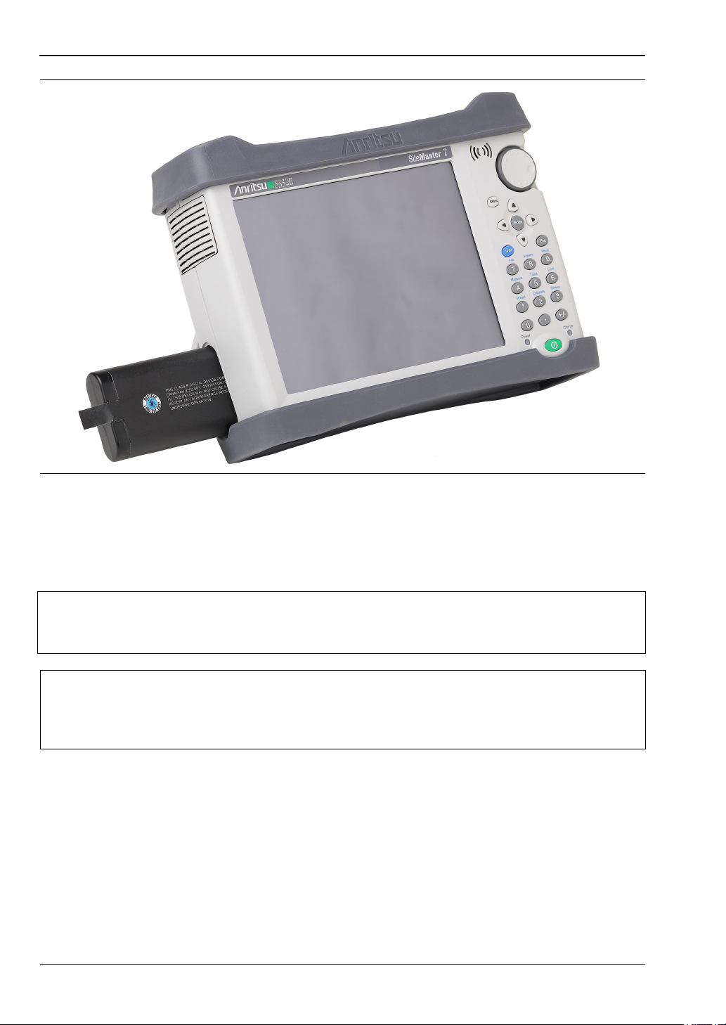
Battery Replacement
The battery can be replaced without the use of tools. The battery compartment door is located
on the lower left side of the instrument (when you are facing the measurement display). To
remove the battery:
1. Slide the catch toward the bottom of the instrument.
2. Pull the top of the door away from the unit.
3. Lift out the battery door.
4. Pull straight out on the lanyard to remove the battery pack from the instrument.
Note
When inserting the battery, the battery label should face the back of the instrument
and the end where the battery contacts are located slides in first. If the battery
door does not latch closed, the battery may be inserted incorrectly.
1-6 Instrument Care and Preventive Maintenance General Information
1-8 PN: 10580-00250 Rev. AA Cell Master UG
The battery that is supplied with the Cell Master may need charging before use. The battery
can be charged while it is installed in the Cell Master by using the AC-DC Adapter, or outside
the Cell Master with the optional Dual Battery Charger. Refer to “Symbols and Indicators”
on page 2-9 for a description of battery symbols.
Figure 1-1. Battery Compartment
Note
Use only Anritsu Company approved batteries, adapters, and chargers with this
instrument. Anritsu recommends removing the battery for long-term storage of the
instrument.
Caution
When using the Automotive Power Adapter, always verify that the supply is rated
for a minimum of 60 Watts @ 12 VDC, and that the socket is clear of any dirt or
debris. If the adapter plug becomes hot to the touch during operation, discontinue
use immediately.

General Information 1-7 Secure Environment Workplace
Cell Master UG PN: 10580-00250 Rev. AA 1-9
1-7 Secure Environment Workplace
This section details the types of memory in the Cell Master, how to delete stored user files in
internal memory, and recommended usage in a secure environment workplace.
Cell Master Memory Types
The instrument contains non-volatile disk-on-a-chip memory, EEPROM, and volatile DRAM
memory. The instrument does not have a hard disk drive or any other type of volatile or
non-volatile memory.
Disk-On-A-Chip (DOC): DOC is used for storage of instrument firmware, factory calibration
information, user measurements, setups, and .jpg screen images. User information stored on
the DOC is erased by the master reset process described below.
EEPROM: This memory stores the model number, serial number, and calibration data for the
instrument. Also stored here are the user-set operating parameters such as frequency range.
During the master reset process, all operating parameters stored in the EEPROM are set to
standard factory default values.
RAM Memory: This is volatile memory used to store parameters needed for the normal
operation of the instrument along with current measurements. This memory is reset
whenever the instrument is restarted.
External USB Flash Drive (not included with the instrument): This memory may be selected
as the destination for saved measurements and setups for the instrument. The user can also
copy the contents of the internal disk-on-chip memory to the external flash memory for
storage or data transfer. The external Flash USB can be reformatted or sanitized using
software on a PC.
Refer to the Chapter 4, “File Management” for additional information on saving and copying
files to the USB flash drive.
Erase All User Files in Internal Memory
Perform a Master Reset:
1. Turn the instrument on.
2. Press the Shift button, then the System (8) button.
3. Press the System Options submenu key.
4. Press the Reset key, then the Master Reset key.
A message box will be displayed to warn the user that all settings will be returned to
factory default values and all user files will be deleted. This is a standard file deletion
and does not involve overwriting existing information.
5. Press the ENTER button to complete the master reset.
6. The instrument will reboot and the reset is complete.

1-7 Secure Environment Workplace General Information
1-10 PN: 10580-00250 Rev. AA Cell Master UG
Recommended Usage in a Secure Environment
Set the instrument to save files to the external USB Flash drive:
1. Attach the external Flash drive and turn the instrument on.
2. Press the Shift button, then the File (7) button.
3. Press the Save submenu key.
4. Press the Change Save Location submenu key, then select the USB drive with the
rotary knob, Up/Down arrow keys, or the touch screen.
5. Press the Set Location submenu key.
The external USB drive is now the default location for saving files.
Note
Not all USB drives are compatible with the instrument. Many drives come with a
second partition that contains proprietary firmware. This partition must be
removed. Only one partition is allowed. Refer to the individual manufacturer for
instructions on how to remove it. Some drives can be made to work by reformatting
them using the FAT32 format.

Cell Master UG PN: 10580-00250 Rev. AA 2-1
Chapter 2 — Instrument Overview
2-1 Introduction
This chapter provides an overview of the Anritsu Cell Master. It describes the instrument
front panel, touch screen display, and the connector panel. For detailed information on the
instrument’s test and measurement functions, refer to one of the Anritsu user documents
listed in Appendix A, “Measurement Guides”.
2-2 Turning On the Cell Master
The Anritsu Cell Master is capable of approximately three hours of continuous operation from
a fully charged, field-replaceable battery (refer to “Battery Replacement” on page 1-7). The
Cell Master can also be operated from a 12 VDC source (which will simultaneously charge the
battery). This can be achieved with either the Anritsu AC-DC Adapter or the Automotive
Power Adapter. Both items are included as standard accessories with the Cell Master. Refer
to the instrument Technical Data Sheet.
To turn on the Cell Master, press the green On/Off button on the front panel (see Figure 2-1
on page 2-2).
The Cell Master takes approximately 60 seconds to complete power-up and to load the
application software. At the completion of this process, the instrument is ready for use.
Caution
When using the Automotive Power Adapter, always verify that the supply is rated
for a minimum of 60 Watts @ 12 VDC, and that the socket is clear of any dirt or
debris. If the adapter plug becomes hot to the touch during operation, discontinue
use immediately.
Note
Keep the fan inlet and exhaust port clear of obstructions at all times for proper
ventilation and cooling of the instrument.
2-3 Instrument Front Panel Instrument Overview
2-2 PN: 10580-00250 Rev. AA Cell Master UG
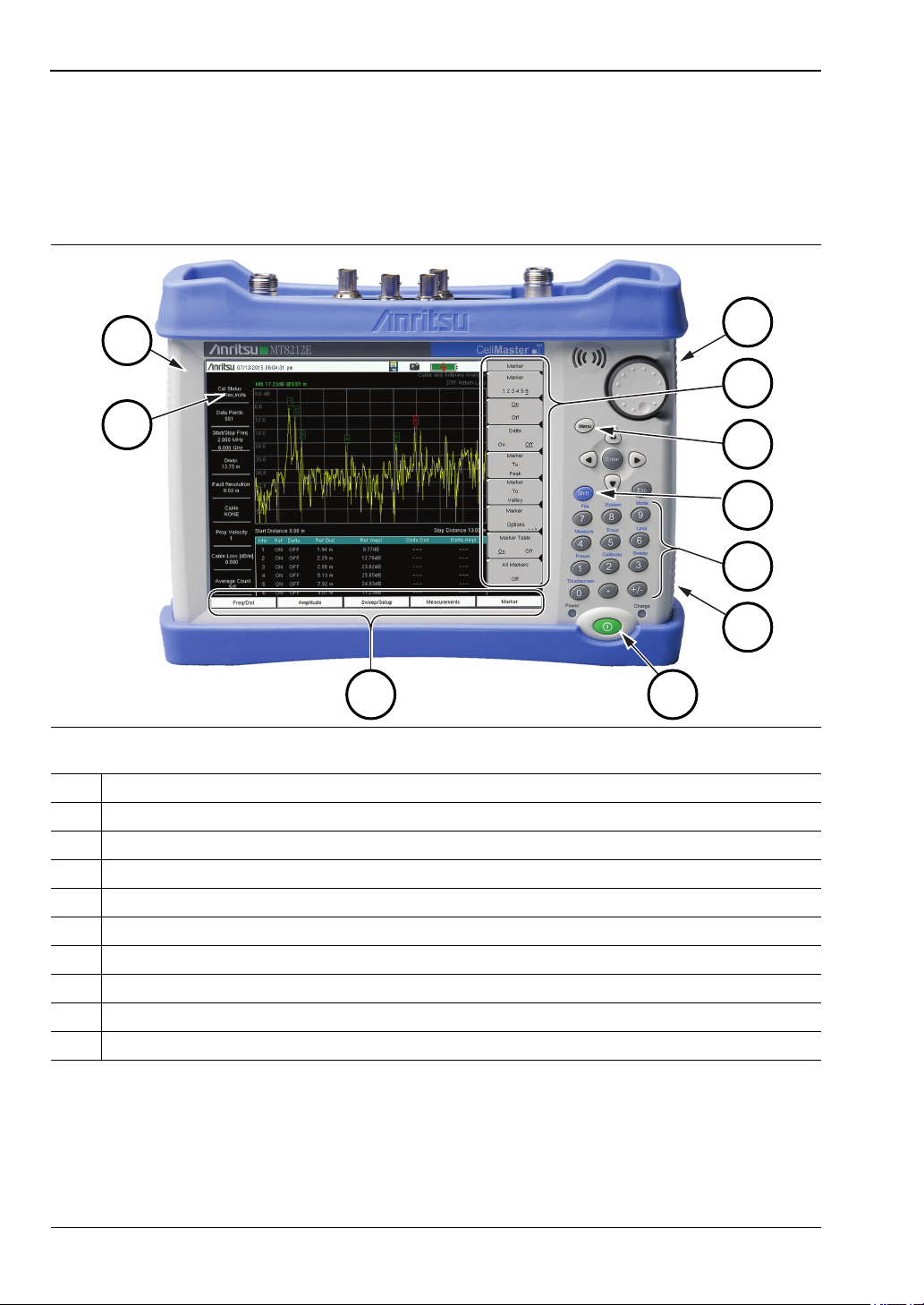
2-3 Instrument Front Panel
The Cell Master uses a touch screen and keypad for data input. See Figure 2-1. The five
bottom menu keys and up to eight submenu keys on the right side of the display are touch
screen keys. The menu and submenu keys vary depending on the current measurement mode,
installed options, and instrument function selected.
Figure 2-1. Cell Master Front Panel and Interface Screen
1. Fan Inlet Port
2. Touch Screen Submenu Keys
3. Menu Key
4. Shift Key
5. Numeric Keypad and Shift Menu Keys (0 to 9, printed in blue above each key)
6. Fan Inlet Port
7. On/Off Button
8. Touch Screen Main Menu Keys
9. Calibration Status and Type
10. Fan Exhaust Port
1
2
3
4
5
6
7
8
9
10
Instrument Overview 2-3 Instrument Front Panel
Cell Master UG PN: 10580-00250 Rev. AA 2-3
LED Indicators
Power LED
The Power LED is located on the left of the On/Off button. The LED is solid green when the
instrument is on, and blinks slowly when the unit is off but is connected to an external power
source.
Charge LED
The Charge LED is located on the right of the On/Off button. The LED blinks slowly when the
battery is charging and is solid green when the battery is fully charged.
Front Panel Keys
The numeric keypad, rotary knob, and the four arrow keys can all be used to change the value
of the currently selected parameter.
Numeric Keypad
Keys 0 through 9 are used for numeric input, with an alternate function printed in blue above
each of the keys. Press the Shift key, then a numeric key, to access the instrument menu or
function indicated by the key label.
Some of the alternate functions associated with the numeric keypad are not available in all
measurement modes. Refer to the Measurement Guides listed in Appendix A.
Shift Key
Pressing the Shift key followed by a number key executes the function that is indicated in
blue above the number key. When the Shift key is active, its icon is displayed at the far right
of the title bar, above the sweep window.
Esc Key
Press this key to cancel the parameter change being made and exit the current menu
function, if applicable.
Arrow Keys
The four arrow keys are used to scroll through a list and highlight the item you wish to select,
or to change the value of the currently selected parameter. The arrow keys can also be used to
move markers. The rotary knob performs similar functions.
Enter Key
Press this key to apply a parameter value or instrument setting you have entered, or to select
a highlighted item from a list.
Figure 2-2. Shift Key Icon in Title Bar
2-3 Instrument Front Panel Instrument Overview
2-4 PN: 10580-00250 Rev. AA Cell Master UG
Rotary Knob
Turn the rotary knob to change numerical values, scroll through selectable items in a list, or
to move markers. Values or items may be within a dialog box or an edit window.
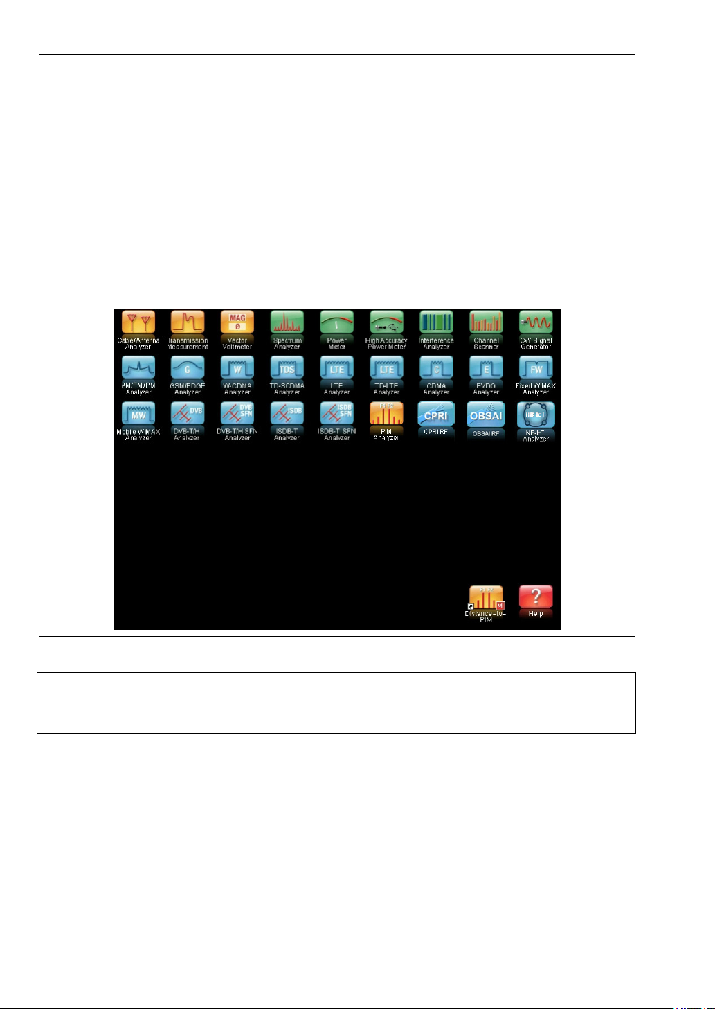
Menu Key
The Menu key displays a grid of shortcut icons for installed measurement modes and
user-selected menus and setup files. See Figure 2-3. Press one of the icons in the top rows to
switch to the corresponding application. These icons are system-generated and cannot be
moved or deleted.
An alternative to the Menu key is to press Shift, then the Mode (9) key to display the Mode
Selector list box. Refer to “Mode Selector” on page 2-16.
Figure 2-3. Menu Key Screen
Note
Shortcut icons displayed in the top rows of the Menu screen vary with the
instrument model, firmware version, and installed options. Help for the Menu
screen is available by pressing the icon in the lower right corner of the display.
Instrument Overview 2-3 Instrument Front Panel
Cell Master UG PN: 10580-00250 Rev. AA 2-5
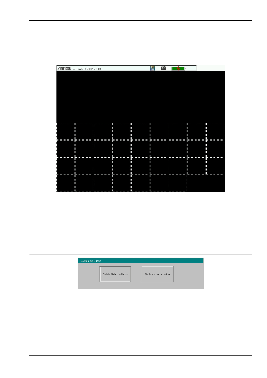
User-Created Shortcuts
To create a shortcut to any submenu key or main menu key, press and hold the key until a
grid appears, showing the open locations on the Menu screen where you can place the new
shortcut. Press one of the cells in the displayed grid to place the shortcut. See Figure 2-4.
To create a shortcut to a setup file (.stp), press Recall under the File menu, then press and
hold the desired file name until a grid is displayed. Select the display location of the new
shortcut as described above.
User-defined shortcuts remain on the Menu screen until deleted. To delete or move a shortcut
icon, press the Menu key, then press and hold the shortcut until the Customize Button dialog
appears. See Figure 2-5. Press the appropriate button to delete or move the shortcut icon.
Press Esc to close the dialog without deleting or moving the shortcut. Also use Esc to exit the
Menu screen.
Figure 2-4. Placement Grid for User-Created Shortcuts
Figure 2-5. Customize Button Dialog
2-4 Interface Screen Instrument Overview
2-6 PN: 10580-00250 Rev. AA Cell Master UG
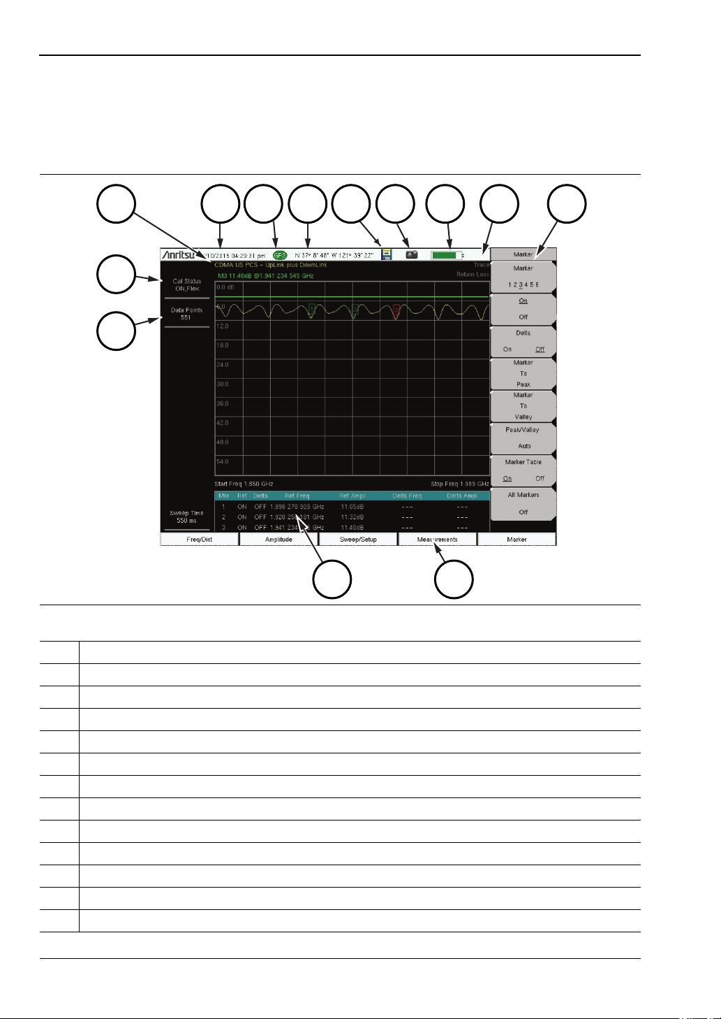
2-4 Interface Screen
Figure 2-6 and Figure 2-7 illustrate the Cell Master interface screen in Cable & Antenna
mode and Spectrum Analyzer mode, with touch screen menu keys, title bar, and
measurement settings and results around the graph area, or sweep window.
Figure 2-6. Cable & Antenna Analyzer Return Loss Measurement Display
1. Measurement Settings Summary
2. Calibration Status, Type
3. Frequency Standard
4. Date and Time
5. GPS Icon
6. GPS Location
7. Save Icon
8. Save Screen Icon
9. Battery Charge Indicator
10. Trace Measurement Title
11. Submenu Touch Screen Keys
12. Main Menu Touch Screen Keys
13. Marker Table
1
2
3
4
5 6
7
8
9
10
11
1213
Instrument Overview 2-4 Interface Screen
Cell Master UG PN: 10580-00250 Rev. AA 2-7
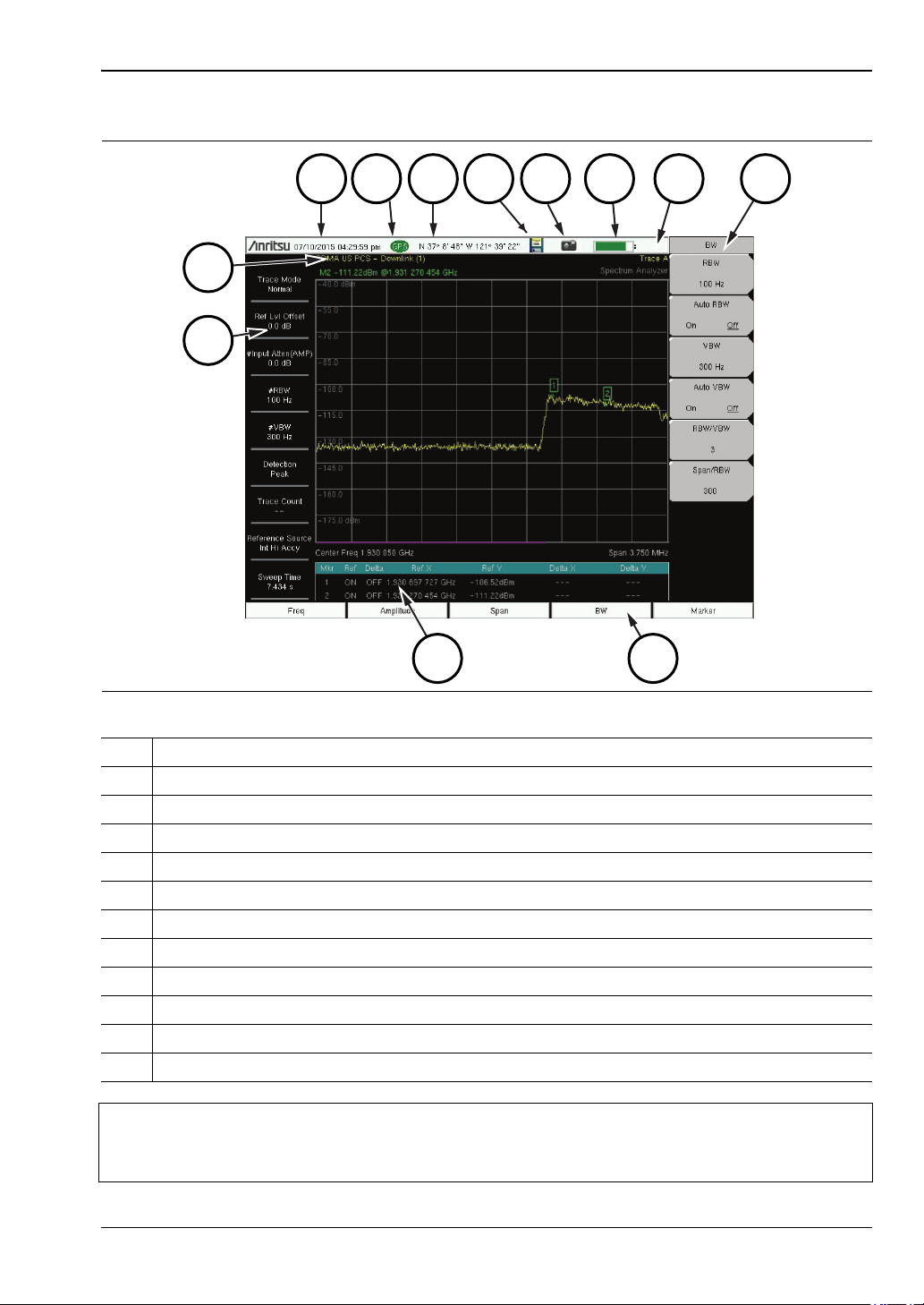
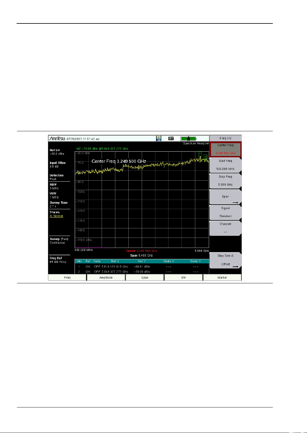
Figure 2-7. Spectrum Analyzer Display
1. Measurement Settings Summary (Touch Screen Shortcuts)
2. Frequency Standard
3. Date and Time
4. GPS Icon
5. GPS Location
6. Save Icon
7. Save Screen Icon
8. Battery Charge Indicator
9. Trace Measurement Title
10. Submenu Touch Screen Keys
11. Main Menu Touch Screen Keys
12. Marker Table
Note
Many of the measurement settings displayed to the left and the top of the sweep
window are actually touch screen shortcuts that you can press to bring up the
corresponding menu.
1
2
1112
3
4 5
6
7
8
9
10
2-4 Interface Screen Instrument Overview
2-8 PN: 10580-00250 Rev. AA Cell Master UG
Touch Screen Keys
Main Menu Touch Screen Keys
There are five main menu keys horizontally arranged along the bottom of the interface
screen. These keys give access to the instrument’s test and measurement functions, which are
documented in the applicable Measurement Guide. Refer to Appendix A, “Measurement
Guides”.
Different operation or measurement modes may display different main menu keys. To switch
to another mode, press the Menu key, or press Shift followed by the Mode (9) key.
Submenu Touch Screen Keys
Most of the instrument setup, control, and measurement functions are performed through the
use of the submenu keys along the right side of the display. The key labels change as
measurement settings and instrument setup parameters change. The current submenu title
is displayed at the top of the submenu key block, which consists of up to eight touch screen
keys. See Figure 2-6 on page 2-6.
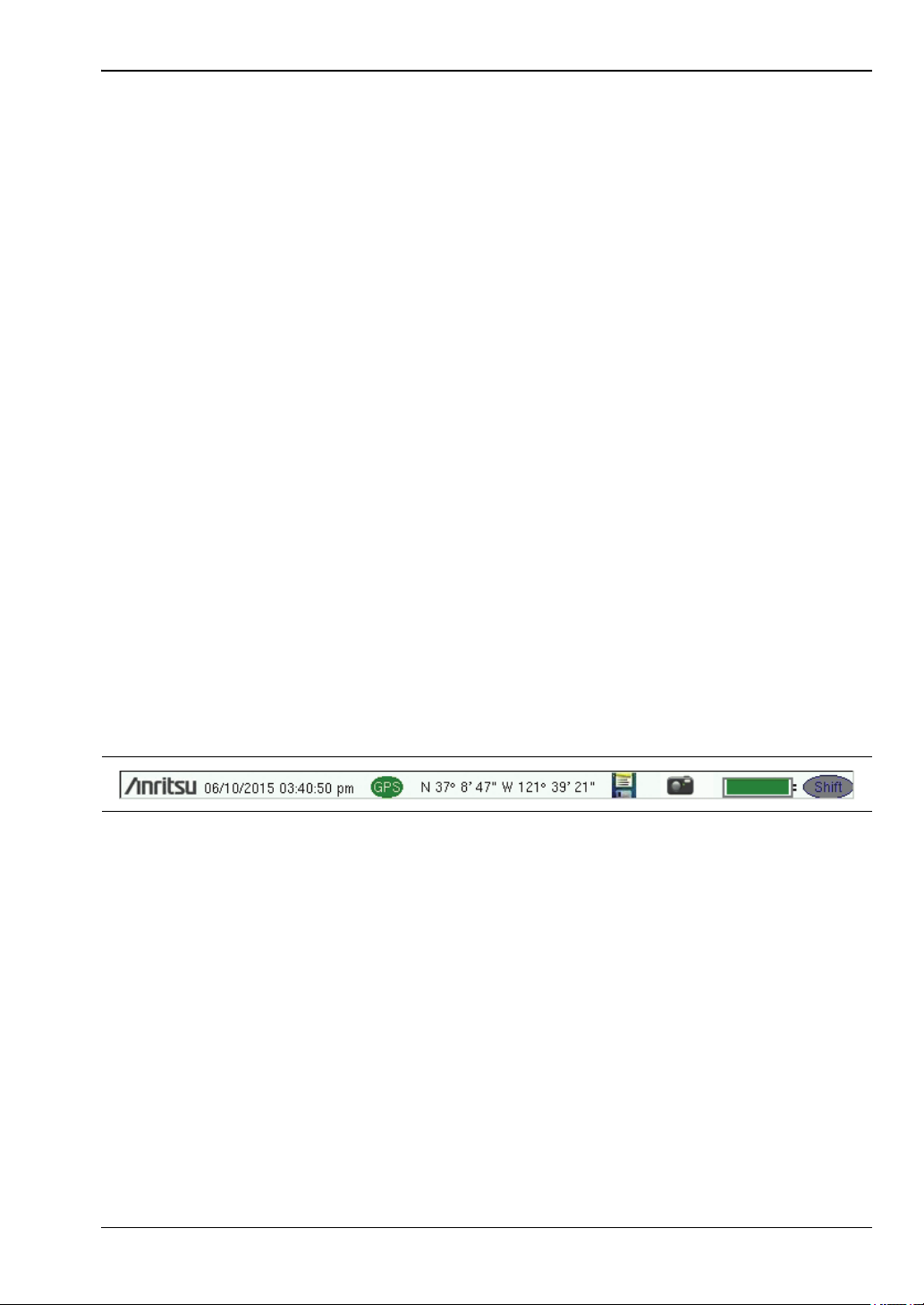
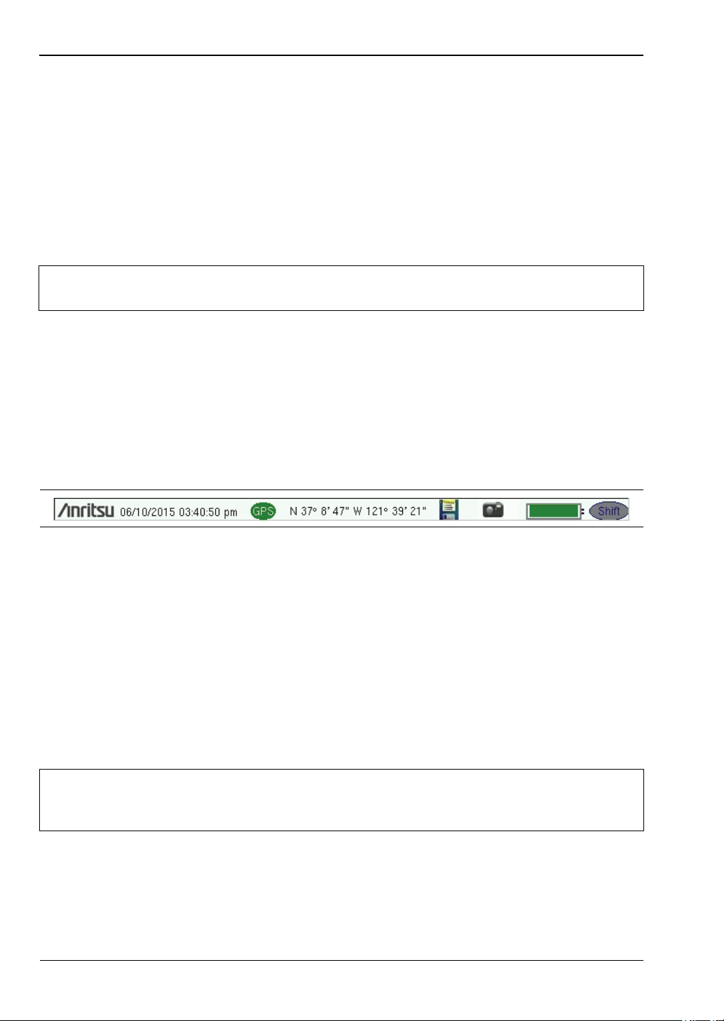
Symbols and Icons on the Title Bar
The instrument title bar displays the system date and time. When GPS is on and is tracking
satellites, its icon is followed by latitude and longitude coordinates.
Press the storage icon to open the touch screen keyboard for saving measurements, setups,
limit lines, or screen display JPEG files. This shortcut to the “Save Menu” on page 4-11 is
equivalent to pressing Shift and File (7), then Save. Refer to “Save Dialog Box” on page 4-3.
Press the camera icon to save a JPEG image of the current screen display.
The battery symbol indicates the charge remaining in the battery. The colored section inside
the symbol changes size and color with the charge level. The Battery Charge LED (adjacent to
the On/Off button) flashes when the battery is charging, and remains on steady when the
battery is fully charged.
The Shift icon is displayed after the Shift key is pressed, and it remains displayed until
another button is pressed.
Note
The instrument model and installed options determine what measurement modes
are available. Refer to Table 1-1 and Table1-2 onpage1-4.
Figure 2-8. Title Bar with Icons
Caution
Use only Anritsu-approved batteries, adapters, and chargers with this instrument.
Anritsu Company recommends removing the battery for long-term storage of the
instrument.
Instrument Overview 2-4 Interface Screen
Cell Master UG PN: 10580-00250 Rev. AA 2-9
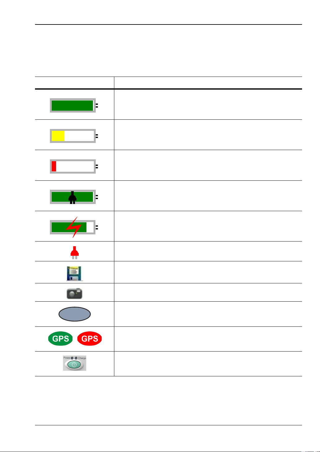
Symbols and Indicators
The following symbols, icons, and indicators convey the instrument status or condition on the
display. The colors shown here are in the standard or default display mode.
Table 2 - 1. Symbols and Icons
Symbol Description
Green: Battery is 30% to 100% charged.
Yellow: Battery is 10% to 30% charged.
Red: Battery is 0% to 10% charged.
Green with Black Plug body: Battery is fully charged and
external power is applied.
Lightning Bolt: Battery is being charged (any color symbol).
Red Plug body: External power is applied, and no battery is
installed, or battery has lost communications with the instrument.
Storage Icon: Tap the floppy disk icon to display the Save screen
and menu.
Camera Icon: Saves a JPEG image of the current screen display.
Shift Key Icon: This icon is displayed between the battery symbol
and the submenu keys after the Shift key has been pressed, and
until another key is pressed.
GPS Icon: This icon is displayed right after the date and time
when GPS is available. Refer to Chapter 6, “GPS (Option 31) ” for
details.
Power Button with Power LED and Charge LED: This is a
physical button with LED indicators. It is located near the numeric
keypad.
Shift
2-4 Interface Screen Instrument Overview
2-10 PN: 10580-00250 Rev. AA Cell Master UG
Display Settings
The Display Settings submenu lets you adjust the screen brightness level and control the
auto-dimming function. Refer to “Brightness Settings Menu” on page 5-8.
You can also turn off the display entirely, as described in “Display Settings Menu”
on page 5-7. To turn the display back on, press any key (except the Power button) three times
in rapid succession.
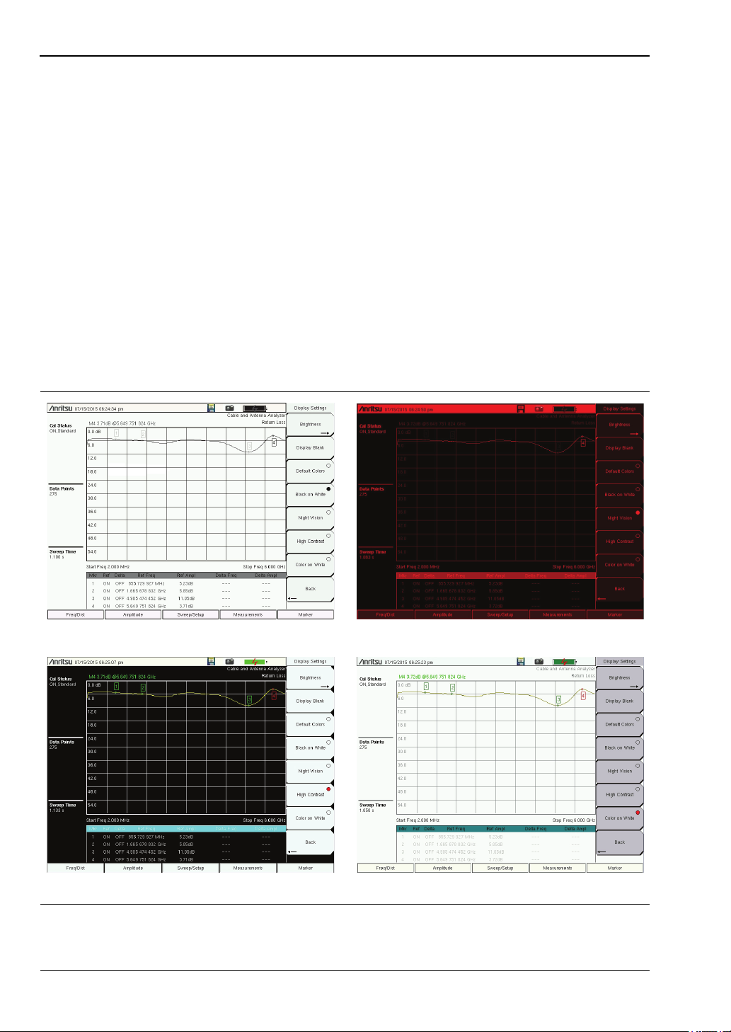
In addition to the default display colors shown in Figure 2-6 on page 2-6, you can select
different color schemes to suit the ambient lighting conditions. See Figure 2-9. Some color
settings may not be available in all measurement modes.
Black on White — used for printing and viewing in broad daylight conditions
Night Vision — optimized for nighttime viewing
High Contrast — used in challenging viewing conditions
Color on White — used for printing and viewing in broad daylight conditions
Figure 2-9. Cell Master Display Color Settings
Black on White Night Vision
Color on WhiteHigh Contrast
Instrument Overview 2-4 Interface Screen
Cell Master UG PN: 10580-00250 Rev. AA 2-11
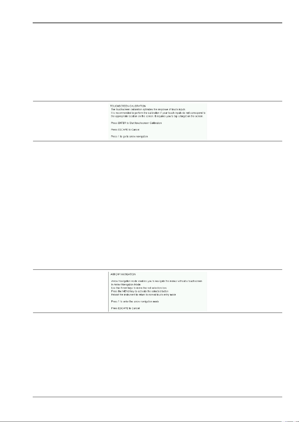
Touch Screen Calibration
Calibration optimizes the response of touch input. It is recommended if the instrument does
not respond as expected when you press the touch screen.
The Calibrate Touch Screen submenu key is in the “System Menu” on page 5-3. When pressed,
a message box is displayed with instructions for calibration. See Figure 2-10. Press Enter to
begin calibration, or press Esc to cancel. Alternatively, you can press 1 while the message box
is displayed to use the arrow keys for navigation. Refer to “Disable Touch Screen to Use
Arrow Navigation”.
During calibration, press the crosshairs in sequence as they appear on the screen. The
process takes less than one minute.
Calibrate Touch Screen Shortcut
Another way to access touch screen calibration is to press Shift, then 0 (zero). This displays
the touch screen calibration message box shown in Figure 2-10. The shortcut can be used if
your touch inputs do not correspond to the appropriate locations on the screen to such an
extent that you cannot access the Calibrate Touch Screen submenu key.
Disable Touch Screen to Use Arrow Navigation
If the touch screen is not functioning, you can use Arrow Navigation to simulate pressing the
touch screen main menu keys and submenu keys. From the touch screen calibration message
box (see Figure 2-10), press 1 to display the arrow navigation message box, illustrated in
Figure 2-11. Press 1 again to enter the arrow navigation mode, or press Esc to cancel.
In arrow navigation mode, a red border highlights the currently selected key (see Figure 2-12
on page 2-12). Use the arrow keys to move the red selection box, then press the Menu key to
activate the highlighted key. Only the main menu keys and submenu keys can be activated
using Arrow Navigation. This feature does not move the red selection box into other areas of
the touch screen, like the display title bar, sweep window, or the instrument settings area on
the left.
Figure 2-10. Touch Screen Calibration Message Box
Figure 2-11. Arrow Navigation Message Box
2-4 Interface Screen Instrument Overview
2-12 PN: 10580-00250 Rev. AA Cell Master UG
To save a measurement in arrow navigation mode, press Shift then File (7). Use the arrow
keys to move the red selection box to the Save Measurement As submenu key. This submenu
key must be used because the arrow navigation mode cannot be used to change data in popup
windows in the measurement display. File names are determined by the current setting of the
Save Measurement As submenu key. Refer to “Save Measurement As” on page 4-10.
You can save a JPEG image of the current display screen by pressing Shift, followed by
Decimal, then +/–. The JEPG image shows screen data, but does not contain the additional
measurement information that accompanies a saved measurement in a *.spa measurement
file.
To return to normal touch entry mode, reboot the instrument (turn power Off, then On). If
your touch screen has been damaged, refer to “Contacting Anritsu for Sales and Service”
on page 1-3.
Figure 2-12. Arrow Navigation Example

Instrument Overview 2-4 Interface Screen
Cell Master UG PN: 10580-00250 Rev. AA 2-13
Calibration Symbols
The current calibration status and type are displayed in the upper-left of the screen when in
Cable & Antenna Analyzer mode. See Figure 2-6 on page 2-6. The five status messages are
described next.
Cal Status: ON, Flex
The Cell Master has been calibrated with discrete Open, Short, and Load components. This is
a FlexCal calibration indicating it is possible to change the frequency range after calibration.
Cal Status: ON, Standard
The Cell Master has been calibrated with discrete Open, Short, and Load components. This is
a Standard calibration indicating it is not possible to change the frequency range after
calibration without performing another calibration.
Cal Status: ON, Flex, Insta
The Cell Master has been calibrated with the InstaCal module. This is a FlexCal calibration
indicating it is possible to change the frequency range after calibration.
Cal Status: ON, Standard, Insta
The Cell Master has been calibrated with the InstaCal module. The Cell Master has been
calibrated with discrete Open, Short, and Load components. This is a Standard calibration
indicating it is not possible to change the frequency range after calibration without
performing another calibration.
Cal Status Off:
The Cell Master has not been calibrated.
For calibration procedures, refer to the Cable & Antenna Measurement Guide
(PN: 10580-00241) listed in Appendix A.

2-5 Data Entry Instrument Overview
2-14 PN: 10580-00250 Rev. AA Cell Master UG
2-5 Data Entry
User input can be in the form of numeric values for instrument or measurement settings,
selected values from a preset list, or alphanumeric text when entering file names, for
example. To view or change a parameter value, access the appropriate submenu by pressing
one of the five main menu keys along the bottom of the interface screen, then navigating
through the touch screen submenus.
Other instrument functions are accessible from the numeric keypad, when used in
combination with the Shift key. Refer to “Numeric Keypad” on page 2-3. Some of the
parameter settings displayed on the left of the interface screen or under the title bar are
touch screen shortcuts to related submenus.
Depending on the measurement mode, refer to the associated Measurement Guide listed in
Appendix A for a description of available menus and submenus.
Numeric Values
To modify a numeric parameter setting that is displayed on a submenu touch screen key,
press the key to make it active. The display color of the currently set value changes to red.
Use the rotary knob, arrow keys, or the numeric keypad to change the value. When entering a
value from the keypad, the submenu typically shows the selectable units. Press the desired
unit or press Enter to complete the entry.
Selection Lists
Some parameters and instrument functions are selectable from a pop-up list. These list boxes
display the available selections, and value limits if applicable. Use the arrow keys or the
rotary knob to scroll through the list and highlight the desired entry. You can also use the
touch screen to make your selection.
To apply the selection, press Enter. To exit the selection list without making a change, press
the Escape (Esc) key.
Loading...