


MU909011A
Table of contents
 Loading...
Network Master Series
MT9090A
Mainframe
MU909011A
Drop Cable Fault Locator Module
Operation Manual
13th Edition
For safety and warning information, please read this
manual before attempting to use the equipment.
Keep this manual with the equipment.
ANRITSU CORPORATION
Document No.: M-W2988AE-13.0

8 October 2007 (First Edition)
20 February2015 (13th Edition)
Copyright©2007-2015 ANRITSU CORPORATION
All rights reserved.
This document and the product to which it relates are
protected by copyright law from unauthorized reproduction.
Notice to U.S. Government End Users
The Software and Documentation are “Commercial Items,”
as that term is defined at 48 C.F.R. 2.101, consisting of
“Commercial Computer Software” and “Commercial
Computer Software Documentation,” as such terms are used
in 48 C.F.R. 12.212 or 48 C.F.R. 227.7202, as applicable.
Consistent with 48 C.F.R. 12.212 or 48 C.F.R. 227.7202-1
through 227.7202-4, as applicable, the Commercial
Computer Software and Commercial Computer Software
Documentation are being licensed to the U.S. Government
end users (a) only as Commercial Items and (b) with only
those rights as are granted to all other end users pursuant to
the terms and conditions herein. Unpublished rights reserved
under the copyright laws of the United States.
• The contents of this manual may be changed
without prior notice.
• No part of this manual may be reproduced without
the prior written permission of the publisher.
ii MT9090A/MU909011A Network Master User’s Guide
Safety Symbols
To prevent the risk of personal injury or loss related to
equipment malfunction, Anritsu Corporation uses the
following safety symbols to indicate safety-related
information. Ensure that you clearly understand the
meanings of the symbols BEFORE using the equipment.
Some or all of the following symbols may be used on all
Anritsu equipment. In addition, there may be other labels
attached to products that are not shown in the diagrams in
this manual.
Symbols used in manual
DANGER This indicates a very dangerous procedure
that could result in serious injury or death
if not performed properly.
WARNING This indicates a hazardous procedure that
could result in serious injury or death if
not performed properly.
CAUTION This indicates a hazardous procedure or
danger that could result in light-to-severe
injury, or loss related to equipment
malfunction, if proper precautions are not
taken.
MT9090A/MU909011A Network Master User’s Guide iii
Safety Symbols Used on Equipment and in
Manual
The following safety symbols are used inside or on the
equipment near operation locations to provide information
about safety items and operation precautions. Ensure that
you clearly understand the meanings of the symbols and take
the necessary precautions BEFORE using the equipment.
This indicates a prohibited operation. The
prohibited operation is indicated symbolically
in or near the barred circle.
This indicates an obligatory safety precaution.
The obligatory operation is indicated
symbolically in or near the circle.
This indicates a warning or caution. The
contents are indicated symbolically in or near
the triangle.
This indicates a note. The contents are
described in the box.
These indicate that the marked part should be
recycled.
iv MT9090A/MU909011A Network Master User’s Guide
For Safety
WARNING
!
• ALWAYS refer to the Operation
Manual when working near
locations at which the alert mark
shown on the left is attached. If
the advice in the Operation
Manual is not followed there is a
risk of personal injury or
reduced equipment
performance. The alert mark
shown on the left may also be
used with other marks and
descriptions to indicate other
dangers.
• Overvoltage Category
This equipment complies with
overvoltage category II defined
in IEC 61010. DO NOT
connect this equipment to the
power supply of overvoltage
category III or IV.
MT9090A/MU909011A Network Master User’s Guide v
Repair
• Laser radiation warning
• NEVER look directly into
the cable connector on the
equipment nor into the end
of a cable connected to the
equipment. There is a risk
of injury if laser radiation
enters the eye.
• The Laser Safety label is
attached to the equipment
for safety use as indicated in
“Laser Radiation Markings
and Laser Aperture” on
page xiv.
• Only qualified service personnel
with a knowledge of electrical
fire and shock hazards should
service this equipment. This
equipment cannot be repaired
by the operator. DO NOT
attempt to remove the
equipment covers or unit covers
or to disassemble internal
components. There are highvoltage parts in this equipment
presenting a risk of severe injury
or fatal electric shock to
untrained personnel. In
addition, there is a risk of
damage to precision
components.
vi MT9090A/MU909011A Network Master User’s Guide
Calibration • he performance-guarantee seal
verifies the integrity of the
equipment. To ensure the
continued integrity of the
equipment, only Anritsu service
personnel, or service personnel
of an Anritsu sales
representative, should break this
seal to repair or calibrate the
equipment. Be careful not to
break the seal by opening the
equipment or unit covers.If the
performance-guarantee seal is
broken by you or a third party,
the performance of the
equipment cannot be
guaranteed.
Replacing
Battery
• When replacing the battery, use
the specified battery and insert it
with the correct polarity. If the
wrong battery is used, or if the
battery is inserted with reversed
polarity, there is a risk of
explosion causing severe injury
or death.
MT9090A/MU909011A Network Master User’s Guide vii

Battery Fluid • DO NOT short the battery
terminals and never attempt to
disassemble the battery or
dispose of it in a fire. If the
battery is damaged by any of
these actions, the battery fluid
may leak. This fluid is
poisonous.
DO NOT touch the battery
fluid, ingest it, or get in your
eyes. If it is accidentally
ingested, spit it out immediately,
rinse your mouth with water and
seek medical help. If it enters
your eyes accidentally, do not
rub your eyes, rinse them with
clean running water and seek
medical help. If the liquid gets
on your skin or clothes, wash it
off carefully and thoroughly.
Battery
Disposal
• DO NOT expose batteries to
heat or fire. Do not expose
batteries to fire. This is
dangerous and can result in
explosions or fire. Heating
batteries may cause them to leak
or explode.
viii MT9090A/MU909011A Network Master User’s Guide

LCD • This instrument uses a Liquid
Crystal Display (LCD). DO
NOT subject the instrument to
excessive force or drop it. If the
LCD is subjected to strong
mechanical shock, it may break
and liquid may leak.
This liquid is very caustic and
poisonous.
DO NOT touch it, ingest it, or
get in your eyes. If it is ingested
accidentally, spit it out
immediately, rinse your mouth
with water and seek medical
help. If it enters your eyes
accidentally, do not rub your
eyes, rinse them with clean
running water and seek medical
help. If the liquid gets on your
skin or clothes, wash it off
carefully and thoroughly.
Laser Safety
Class 1and 3R indicate the danger degree of laser radiation
specified below according to IEC 60825-1:200
Class 1: Lasers that are safe under reasonably foreseeable
conditions of operation, including the use of
optical instruments for intrabeam viewing.
MT9090A/MU909011A Network Master User’s Guide ix
7.

CAUTION
!
Class 3R: Lasers that emit in the wavelength range from
302.5 to 10
6
nm where direct intrabeam
viewing is potentially hazardous but the risk is
lower than for Class 3B lasers.
Use of controls or adjustments or performance of
procedures other than those specified herein may result
in hazardous radiation exposure.
The use of optical instruments with this product will
increase eye hazard.
x MT9090A/MU909011A Network Master User’s Guide
WARNING
!
Before using this instrument, always ensure that the
Laser On icon is displayed when the optical output
switch is turned on. See Figure 4-19 on page 4-25. If the
icon is not displayed, the equipment may be faulty and
for safety reasons should be returned to an Anritsu
service center or representative for repair.
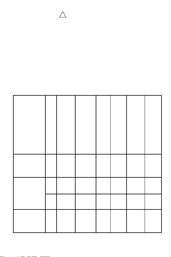
The lasers in this equipment are classified as Class 1 and
Class 3R according to the IEC 60825-1:2007 standard.
Table 1: Laser Safety Classification Based on IEC 60825-1:2007
Model
Class
MU909011A/
A2
–050/060
MU909011A1/
A3
–050/060
MU909011A/
A2
–052/062
Max. Optical
10.10
10.10
3R 0.003 CW 650 11.5 c)
10.01
Output Power (W)*
Pulse Width (s)/
20×10
0.046
20×10
0.046
20×10
0.046
Repetition Rate
Emitted Wavelength (nm)
-9
/
-9
/
-9
/
11.5 a)
1550
1550 11.5 a)
11.5 b)
780
Incorporated Laser
Beam Divergence (deg)
Specification(refer to Table 2)
Laser Aperture
Fig. 1-
[1]
Fig. 1-
[1]
Fig. 1-
[2]
Fig. 1-
[1]
MT9090A/MU909011A Network Master User’s Guide xi
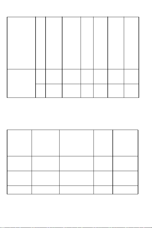
Table 1: Laser Safety Classification Based on IEC 60825-1:2007
Model
Class
MU909011A1/
A3
–052/062
Max. Optical
10.01
3R 0.003 CW 650
Output Power (W)*
Pulse Width (s)/
20×10
0.046
Repetition Rate
Emitted Wavelength (nm)
-9
/
780
11.5 b)
11.5 c)
Beam Divergence (deg)
Incorporated Laser
Specification(refer to Table 2)
* Indicates the possible optical output power when each
and every reasonably foreseeable single-fault condition
is included
Table 2: Incorporated Laser Specification
Laser Aperture
Fig. 1-
[1]
Fig. 1-
[2]
Incorporated
Laser
a) 0.20
b) 0.02
c) 0.003 CW 650 11.5
xii MT9090A/MU909011A Network Master User’s Guide
Maximum
output power*
*
Maximum output power is the estimated value when
something breaks down.
Pulse Width (s)/
Repetition Rate
20×10-9/
0.046
20×10-9/
0.046
Emitted
Wa ve length
Divergence
[nm]
1550 11.5
780 11.5
Beam
(deg)
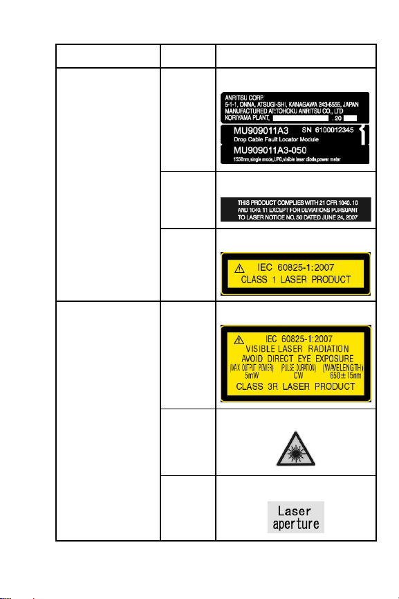
Table 3: Laser Safety Label list
Model Location Type / Label
Fig. 1-A Identification Label
MU909011A/A1/A2/
A3–050/060
MU909011A/A1/A2/
A3 –052/062
Fig. 1-B Certification Label
Fig. 1-C Class 1 Label
Fig. 1-D Class 3R Label
MU909011A1/A3
–050/060
MU909011A1/A3 –
052/062
Fig. 1-E Laser Mark
Fig. 1-F Aperture Label
MT9090A/MU909011A Network Master User’s Guide xiii
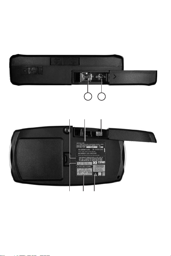
Laser Radiation Markings and Laser Aperture
21
BCA
D E
F
The following figure details the positions of the Laser
aper
tures as well as the various Laser Safety labels. See Ta b le 3
“Laser Safety Label list” on page xiii for details on labels A
through F.
Figure 1: Laser Safety Labels and Laser Apertures
xiv MT9090A/MU909011A Network Master User’s Guide

Electrical Safety
To reduce risk of equipment damage, injury, or death, adhere
to the following warnings:
• DO NOT use the Network Master or its AC
charger/adapter if case for either is cracked or
damaged.
• Use the Network Master only with the AC
charger/adapter provided for the unit by Anritsu.
Anritsu does not guarantee the safety and
functionality of other AC charger/adapters.
• DO NOT use the Network Master AC
charger/adapter in outdoor or wet environments.
• Ensure that the AC input to the external power
supply is within the voltages marked on the power
supply case.
• DO NOT attempt to service the product in any way
other than routine maintenance as described in this
manual.
MT9090A/MU909011A Network Master User’s Guide xv

For Safety
External Storage Media
This equipment uses a USB memory as external storage
media for storing data and programs.
If this media is mishandled or becomes faulty, important
data may be lost. To prevent this chance occurrence, all
important data and programs should be backed-up.
Anritsu will not be held responsible for lost data.
Pay careful attention to the following points.
• Never remove the USB memory from the Network
Master, while it is being accessed.
• The memory card may be damaged by static electric
charges.
Use in a Residential Environment
This instrument is designed for an industrial
environment. In a residential environment this
instrument may cause radio interference in which case
the user may be required to take adequate measures.
Use in Corrosive Atmospheres
Exposure to corrosive gases such as hydrogen sulfide,
sulfurous acid, and hydrogen chloride will cause faults
and failures.
Note that some organic solvents release corrosive gases.
xvi MT9090A/MU909011A Network Master User’s Guide

Equipment Certificate
Anritsu Corporation certifies that this equipment was tested
before shipment using calibrated measuring instruments with
direct traceability to public testing organizations recognized
by national research laboratories, including the National
Institute of Advanced Industrial Science and Technology, and
the National Institute of Information and Communications
Technology, and was found to meet the published
specifications.
Anritsu Warranty
Anritsu Corporation will repair this equipment free-of-charge
if a malfunction occurs within one year after shipment due to
a manufacturing fault.
However, software fixes will be made in accordance with the
separate Software End-User License Agreement. Moreover,
Anritsu Corporation will deem this warranty void when:
• The fault is outside the scope of the warranty
conditions separately described in the operation
manual.
• The fault is due to mishandling, misuse, or
unauthorized modification or repair of the
equipment by the customer.
• The fault is due to severe usage clearly exceeding
normal usage.
• The fault is due to improper or insufficient
maintenance by the customer.
MT9090A/MU909011A Network Master User’s Guide xvii

• The fault is due to natural disaster, including fire,
wind, flooding, earthquake, lightning strike, or
volcanic ash, etc.
• The fault is due to damage caused by acts of
destruction, including civil disturbance, riot, or war,
etc.
• The fault is due to explosion, accident, or
breakdown of any other machinery, facility, or
plant, etc.
• The fault is due to use of non-specified peripheral or
applied equipment or parts, or consumables, etc.
• The fault is due to use of a non-specified power
supply or in a non-specified installation location.
• The fault is due to use in unusual
environments
(Note)
.
• The fault is due to activities or ingress of living
organisms, such as insects, spiders, fungus, pollen,
or seeds.
In addition, this warranty is valid only for the original
equipment purchaser. It is not transferable if the equipment
is resold.
Anritsu Corporation shall assume no liability for injury or
financial loss of the customer due to the use of or a failure to
be able to use this equipment.
xviii MT9090A/MU909011A Network Master User’s Guide

Note
Note
For the purpose of this Warranty, "unusual environments"
means use:
• In places of direct sunlight
• In dusty places
• Outdoors
• In liquids, such as water, oil, or organic solvents, and
medical fluids, or places where these liquids may
adhere
• In salty air or in places where chemically active gases
(sulfur dioxide, hydrogen sulfide, chlorine,
ammonia, nitrogen oxide, or hydrogen chloride
etc.) are present
• In places where high-intensity static electric charges
or electromagnetic fields are present
• In places where abnormal power voltages (high or
low) or instantaneous power failures occur
• In places where condensation occurs
• In the presence of lubricating oil mists
• In places at an altitude of more than 2,000 m
• In the presence of frequent vibration or mechanical
shock, such as in cars, ships, or airplanes
Anritsu Corporation Contact
In the event that this equipment malfunctions, contact an
Anritsu Service and Sales office. Contact information can be
found on the last page of the printed version of this manual,
and is available in a separate file on the CD version.
MT9090A/MU909011A Network Master User’s Guide xix
Notes On Export Management
This product and its manuals may require an Export
License/Approval by the Government of the product's
country of origin for re-export from your country.
Before re-exporting the product or manuals, please contact us
to confirm whether they are export-controlled items or not.
When you dispose of export-controlled items, the
products/manuals need to be broken/shredded so as not to be
unlawfully used for military purpose.
Disposal Procedure
The product that you have purchased contains a rechargeable
battery. The battery is recyclable. At the end of its useful life,
under various state and local laws, it may be illegal to dispose
of this battery into the municipal waste stream. Check with
your local solid waste officials for details in your area for
recycling options or proper disposal.
Crossed-out Wheeled Bin Symbol
Equipment marked with the Crossed-out Wheeled Bin
Symbol complies with council directive 2012/19/EC (the
“WEEE Directive”) in European Union.
For Products placed on the EU market after August 13, 2005,
please contact your local Anritsu representative at the end of
the product's useful life to arrange disposal in accordance
with your initial contract and the local law.
xx MT9090A/MU909011A Network Master User’s Guide

CE Conformity Marking
Anritsu affixes the CE conformity marking on the following
product(s) in accordance with the Council Directive
93/68/EEC to indicate that they conform to the EMC and
LVD directive of the European Union (EU).
CE marking
1. Product Model
Model: MT9090A Mainframe
MU909011A Drop Cable Fault Locator Module
2. Applied Directive
EMC: Directive 2004/108/EC
LV D: Directive 2006/95/EC
3 Applied Standards
• EMC Emission:
EN 61326-1: 2013 (Class A)
Immunity:
EN 61326-1: 2013 (Table 2)
MT9090A/MU909011A Network Master User’s Guide xxi

Per formance
Criteria*
IEC 61000-4-2 (ESD)
IEC 61000-4-3 (EMF)
IEC 61000-4-4 (Burst)
IEC 61000-4-5 (Surge)
IEC 61000-4-6 (CRF)
IEC 61000-4-8 (RPFMF)
IEC 61000-4-11 (V dip/short)
B
A
B
B
A
A
B, C
*: Performance Criteria:
A: The equipment shall continue to operate as
intended during and after the test. No
degradation of performance or loss of
function is allowed below a performance
level specified by the manufacturer, when
the equipment is used as intended. The
performance level may be replaced by a
permissible loss of performance. If the
minimum performance level or the
permissible performance loss is not
specified by the manufacturer, either of
these may be derived from the product
description and documentation and what
the user may reasonably expect from the
equipment if used as intended.
xxii MT9090A/MU909011A Network Master User’s Guide

B:. The equipment shall continue to operate as
intended after the test. No degradation of
performance or loss of function is allowed
below a performance level specified by the
manufacturer, when the equipment is used
as intended. The performance level may be
replaced by a permissible loss of
performance. During the test, degradation
of performance is however allowed. No
change of actual operating state or stored
data is allowed. If the minimum
performance level or the permissible
performance loss is not specified by the
manufacturer, either of these may be
derived from the product description and
documentation and what the user may
reasonably expect from the equipment if
used as intended.
C:. Temporary loss of function is allowed,
provided the function is self-recoverable or
can be restored by the operation of the
controls.
Harmonic current emissions:
EN 61000-3-2: 2006 +A1:2009 A2:2009
(Class A equipment)
: No limits apply for this equipment with an
active input power under 75 W.
• LVD: EN 61010-1: 2010 (Pollution Degree 2)
MT9090A/MU909011A Network Master User’s Guide xxiii

4 Authorized representative
Name:
Address, city:
Country
Murray Coleman
Head of Customer Service EMEA
ANRITSU EMEA Ltd.
200 Capability Green, Luton
Bedfordshire, LU1 3LU
United Kingdom
xxiv MT9090A/MU909011A Network Master User’s Guide

C-Tick Conformity Marking
Anritsu affixes the C-Tick mark on the following product(s)
in accordance with the regulation to indicate that they
conform to the EMC framework of Australia/New Zealand.
C-Tick marking
1. Product Model
Models:
2. Applied Standards
EMC: Emission:
MT9090A Mainframe
MU909011A Drop Cable Fault Locator Module
EN 61326-1: 2013(Class A equipment)
MT9090A/MU909011A Network Master User’s Guide xxv

Technical Support, Services, and Repairs
Our Technical Support Center is at your service to answer
technical questions and provide return authorization for
service, repairs, or other returns.
Technical Support Center
Phone: 1-800-ANRITSU or 972-761-4600
(Canada, U.S., Latin and South America)
Fax: +1 972-671-1877
e-mail: us-sales@anritsu.com
Web: www.anritsu.com
All returns require a Return Materials Authorization (RMA)
number. If possible, return the unit in its original shipping
materials. If the original shipping materials are not available,
please contact the Technical Support Center for instructions.
Whether or not the warranty period of your Anritsu product
has expired, the unit can be returned to Anritsu for repairs.
Out-of-warranty repairs are billed for time and materials. Call
our Technical Support Center for further information.
Anritsu offers a performance verification service that
extensively tests this product and documents its performance.
All test equipment used in the verification process is traceable
to NIST or NPL standards, and is calibrated annually.
Anritsu recommends that you have your unit calibrated
annually at our factory.
xxvi MT9090A/MU909011A Network Master User’s Guide

Safety Symbols iii
For Safety v
For Safety xvi
Equipment Certificate xvii
CE Conformity Marking xxi
C-Tick Conformity Marking xxiv
Technical Support, Services, and Repairs xxv
General Setups4-71-xxvii
Display From4-311-xxviii
Chapter 1: Quick Start1-1
Introduction1-1
Basic Configuration1-2
Powering Up the Unit1-2
Start Up Sequence1-2
Fault Locate Application1-3
VFL Testing1-5
VIP - Video Inspection Probe (Option)1-6
Chapter 2: Overview2-1
Front Panel2-1
LCD Display2-2
Softkeys2-3
Start Key2-3
Arrow Keys and Set Key2-3
Menu/Power Key2-5
Back Panel2-5
Power and Batteries2-6
Installing the Ni-MH battery pack2-7
Battery Replacement – Ni-MH pack to AA
MT9090A/MU909011A Network Master User’s Guide xxvii

Ni-MH2-9
Bottom Panel2-10
Top Connector Panel2-10
AC Charger/Adapter2-12
Battery Status LED2-15
VFL Port2-17
Measurement Port2-17
Connecting Peripheral Devices2-21
Changing the Test Module2-24
Basic Notes on Use2-26
Chapter 3: General Operation and
System Setups3-1
General Operation3-1
Power Up/Power Down3-1
General Functions Pop-up Menu3-4
VFL (Visual Fault Locator)3-6
VIP (Video Inspection Probe)3-8
Setup3-8
Set to Defaults3-14
Load3-16
Help Function3-17
About Function3-17
Mass Storage3-18
Print Screen3-27
Top Menu3-27
Chapter 4: Fault Locate Application4-1
Overview4-1
Starting the Fault Locate Application4-1
Fault Locate Application Setups4-4
xxviii MT9090A/MU909011A Network Master User’s Guide

Fault Locate Preferences Setups4-4
General Setups4-7
Fault Locate Parameters Setups4-7
Auto Save Setups4-9
Power Meter Step Screen4-13
Setting the Power Meter Threshold Value
4-16
Fault Locate Step Screen4-17
Fiber Route – Schematic View4-18
Test Information Area4-19
Total Loss Threshold Indicator4-20
Event Table4-20
Event Description Dialog4-24
Laser On Icon4-25
Trace View Screen4-26
A to B Cursor Distance4-26
2-Point Loss (dB) Measurement4-26
Trace Graph4-27
Softkeys4-29
Display From4-31
Selecting and Positioning Cursors4-31
Zoom In/Zoom Out4-32
Fault Locate Test4-34
Real Time Testing4-37
Connection Check4-38
Working with Fault Locate Trace Files4-40
Loading Trace Files4-40
Saving Trace Files4-40
Chapter 5: Video Inspection Probe (VIP)
Option5-1
MT9090A/MU909011A Network Master User’s Guide xxix

Video Inspection Probe (VIP)5-2
Probe Tips5-2
VIP Setup5-3
Accessing VIP Mode5-8
Exiting VIP Mode5-10
Working with VIP Image Files5-10
Saving VIP Images5-10
Loading a VIP Image5-12
Mass Storage File Operations5-14
Chapter 6: Updating Firmware6-1
Updating the Firmware6-1
Chapter 7: Performance Test
and Calibration7-1
Performance Test7-2
Wavelength7-6
Pulse Width7-7
Dynamic Range
(one-way back-scattered light dynamic range test)7-8
Optical Power Level and Wavelength of Vi-
sual Fault Locator
(MU909011A1 / A3)7-9
Measurement Accuracy of the Optical
Power Meter (MU909011A2 / A3)711
Calibration7-13
Backscatter Coefficient Level Calibration7-
13
Optical Power Meter Calibration7-14
xxx MT9090A/MU909011A Network Master User’s Guide
Loading...