


User Interface Reference Manual
ShockLine™ MS46121A/B, MS46122A/B, MS46131A, MS46322A/B Series Vector Network Analyzers
MS46121A/B, 150 KHz to 6 GHz, 1-port
MS46122A/B, 1 MHz to 43.5 GHz, 2-port
MS46131A, 1 MHz to 43.5 GHz, 1-port
ME7868A, 1 MHz to 43.5 GHz, 2-port
MS46322A/B, 1 MHz to 43.5 GHz, 2-port
Anritsu Company
490 Jarvis Drive
Morgan Hill, CA 95037-2809
USA
http://www.anritsu.com
Part Number: 10410-00337
Copyright 2020 Anritsu Company, USA. All Rights Reserved.
Published: November 2020
Revision: AE


Chapter Descriptions
Chapter 1 — Overview
Chapter 2 — Menu Bar, Icon Bar, and Main Menu
This chapter describes the user interface screen layout, and navigation tools including the Menu Bar,
Icon Bar, and MAIN MENU.
Chapter 3 — Channel Menus
This chapter describes how to set the number of channels used and how they are displayed on the
instrument. Up to 16 channels can be configured, each with up to 16 traces per channel. For the
MS46121A/B only, each channel is dedicated to an individual 1-port VNA. Only those channels
associated with VNA hardware will have active trace displays.
Chapter 4 — Frequency Menus
This chapter covers the FREQUENCY menu which allows the user to set frequency start, stop, span,
number of points, and CW mode parameters for the currently active (selected) channel. The
FREQUENCY menu has several variants; the one that is displayed depends on the Sweep Types setting
for the current channel. The sweep type is set on the SWEEP SETUP menu.
Chapter 5 — Power Menus
This chapter provides information on port power control in MS461xx series and MS463xx series VNAs.
Power conditions for sweeps are set in different places in the ShockLine application, depending on the
sweep type: 1) for frequency-based sweeps, the POWER menu is used to set power parameters, and 2)
for segmented and indexed sweeps, the power setup controls are in segment or index setup
characteristics areas of the sweep table (see Chapter 6 — Sweep Menus for details).
Chapter 6 — Sweep Menus
This chapter describes sweep types supported by the VNA and how to set and configure them.
Chapter 7 — Averaging Menu
The AVERAGING menu allows users to turn averaging on or off, set the averaging factor, and select
whether the averaging type is per point or per sweep. Control is also provided for IFBW and trace
smoothing.
Chapter 8 — Calibration Menus: 1-Port and 2-Port VNAs
This chapter describes the menus used when calibrating 1- and 2-port ShockLine VNAs. It is organized
to follow the flows in the progressions of menus and dialog boxes for calibration control. Though it
provides representative examples of dialogs, it does not show all the possible dialog contents. This is
because their appearance changes dynamically based on combination of instrument calibration ports,
AutoCal™, manual calibration, calibration methods, line types, and connectors. However, basic
elements in the combinations are explained. The calibration menus for MS46121A/B with Option 21
are also explained.
Chapter 9 — Measurement Menus
This chapter provides information for the measurement menu system which controls the
embed/de-embed functions, the impedance transformations, reference plane location, post-processing
order functions, and dielectric parameters along with their related configuration dialog boxes.
Impedance transformation and post-processing order functions do not apply to the MS46121A/B.
Chapter 10 — Time Domain Menu
The Time Domain (TDOMAIN) menu provides a convenient way to access all time domain-related
parameter setup items. Although these parameters are also accessible in other places throughout the
ShockLine application, the user must shift among menus to reach them. Here, the Measurement Setup
dialog collects all of them for access on one screen.
MS46121A/B-122A/B-131A-322A/B Series UIRM PN: 10410-00337 Rev. AE Descriptions-1

Chapter 11 — Application Menu
This chapter provides information for the APPLICATION menu that is used for Receiver Configuration.
The default measurement mode setting is for Standard S-Parameters.
Chapter 12 — Trace Menus
This chapter provides information on traces. You can set the number of traces that appear for each
channel and how those traces are arranged on the main display. Up to 16 traces can be defined and
there are 22 available trace layouts. Traces can be detached as free-floating windows.
Chapter 13 — Response Menus: 1-Port and 2-Port VNAs
This chapter provides information on the 1- and 2-port VNA Response menus used to configure
S-Parameters using standard options, or to configure user-defined parameters. Only 1-port-related
Response menu items apply to the MS46121A/B and MS46131A.
Chapter 14 — Display Menus
This chapter provides information for setup and configuration for the instrument displays. Selections
provide control over the trace formats, with over nine different major display types. Each display type
can be further modified with parameters applicable to that display format. The control also provides
control for trace memory and trace math modifications. The trace limit functions allow
maximum/minimum parameters to be set for each trace and provide visual and/or programmatic
indications of pass/fail.
Chapter 15 — Scale Menus
This chapter provides information about the button controls for the SCALE menu variants. SCALE
menus provide trace display control of settings such as resolution, reference value, and the scale of
units. The number of buttons on a SCALE menu depends on the settings on the TRACE FORMAT menu.
Chapter 16 — Marker Menus
This chapter provides information for configuring and controlling the marker functions. The
instrument provides up to thirteen markers per trace of which twelve can be direct markers and one a
reference marker. Each marker can be individually controlled on/off and positioned as required. If the
reference marker is off, each marker provides measurement data based on its display position. If the
reference marker is on, each marker provides differential measurement data based on its position
relative the reference. Other functions for display options and various types of single-peak search are
available.
Chapter 17 — System Menus
This chapter provides information for various system and instrument management and configuration
functions including initial setup, power-on options, preset options, network interface, self-test, and
diagnostics.
Chapter 18 — File Management Menus
This chapter provides information for management of various system output and configuration files
including Active channel TXT files, Active channel S2P files, Active channel CSV files, Active trace
data (Formatted), and Active trace data (Unformatted).
Appendix A — File Specifications
This appendix defines the file directory structure used on default-configuration ShockLine Series
VNAs and provides the general file extensions and specifications used in the instrument.
Appendix B — Error Messages
This appendix lists, describes, and provides corrective action for error messages that appear on the
instrument display. Messages that require action by a service representative are also listed. The tables
herein describe the name of the message, the typical reason for its occurrence, and recommended error
correction methods.
Descriptions-2 PN: 10410-00337 Rev. AE MS46121A/B-122A/B-131A-322A/B Series UIRM

Appendix C — Anritsu easyTest Tools™
This appendix outlines using easyTest Tools with ShockLine VNAs. The easyTest Tools application is
used to create easyTest .ett files having step sequences that can be run (displayed) on the instrument.
Appendix D — Glossary of Terms
MS46121A/B-122A/B-131A-322A/B Series UIRM PN: 10410-00337 Rev. AE Descriptions-3

Descriptions-4 PN: 10410-00337 Rev. AE MS46121A/B-122A/B-131A-322A/B Series UIRM

Table of Contents
Chapter 1 — Overview
1-1 Introduction. . . . . . . . . . . . . . . . . . . . . . . . . . . . . . . . . . . . . . . . . . . . . . . . . . . . . . . . . . . . . . . . . . 1-1
1-2 ShockLine MS46121A/B, MS46122A/B, MS46131A, MS46322A/B Series VNA Models . . . . . . 1-1
1-3 Documentation Conventions. . . . . . . . . . . . . . . . . . . . . . . . . . . . . . . . . . . . . . . . . . . . . . . . . . . . . 1-2
Instrument Identification . . . . . . . . . . . . . . . . . . . . . . . . . . . . . . . . . . . . . . . . . . . . . . . . . . . 1-2
User Interface . . . . . . . . . . . . . . . . . . . . . . . . . . . . . . . . . . . . . . . . . . . . . . . . . . . . . . . . . . . 1-2
User Interface Navigation . . . . . . . . . . . . . . . . . . . . . . . . . . . . . . . . . . . . . . . . . . . . . . . . . . 1-2
User Input . . . . . . . . . . . . . . . . . . . . . . . . . . . . . . . . . . . . . . . . . . . . . . . . . . . . . . . . . . . . . . 1-2
1-4 User Documentation . . . . . . . . . . . . . . . . . . . . . . . . . . . . . . . . . . . . . . . . . . . . . . . . . . . . . . . . . . . 1-2
Product Information, Compliance, and Safety . . . . . . . . . . . . . . . . . . . . . . . . . . . . . . . . . . . 1-2
ShockLine MS46122A/B Vector Network Analyzers . . . . . . . . . . . . . . . . . . . . . . . . . . . . . . 1-3
ShockLine MS46131A Vector Network Analyzers. . . . . . . . . . . . . . . . . . . . . . . . . . . . . . . . 1-3
ShockLine MS46322A/B Vector Network Analyzers . . . . . . . . . . . . . . . . . . . . . . . . . . . . . . 1-3
Updates to Manuals. . . . . . . . . . . . . . . . . . . . . . . . . . . . . . . . . . . . . . . . . . . . . . . . . . . . . . . 1-3
1-5 Contacting Anritsu . . . . . . . . . . . . . . . . . . . . . . . . . . . . . . . . . . . . . . . . . . . . . . . . . . . . . . . . . . . . 1-3
Chapter 2 — Menu Bar, Icon Bar, and Main Menu
2-1 Chapter Overview . . . . . . . . . . . . . . . . . . . . . . . . . . . . . . . . . . . . . . . . . . . . . . . . . . . . . . . . . . . . . 2-1
2-2 Menu Bar . . . . . . . . . . . . . . . . . . . . . . . . . . . . . . . . . . . . . . . . . . . . . . . . . . . . . . . . . . . . . . . . . . . 2-1
2-3 Icon Bar . . . . . . . . . . . . . . . . . . . . . . . . . . . . . . . . . . . . . . . . . . . . . . . . . . . . . . . . . . . . . . . . . . . . 2-1
2-4 Main Menu . . . . . . . . . . . . . . . . . . . . . . . . . . . . . . . . . . . . . . . . . . . . . . . . . . . . . . . . . . . . . . . . . . 2-2
MAIN MENU . . . . . . . . . . . . . . . . . . . . . . . . . . . . . . . . . . . . . . . . . . . . . . . . . . . . . . . . . . . . 2-2
2-5 Context (Right-Click) Menus. . . . . . . . . . . . . . . . . . . . . . . . . . . . . . . . . . . . . . . . . . . . . . . . . . . . . 2-5
Chapter 3 — Channel Menus
3-1 Chapter Overview . . . . . . . . . . . . . . . . . . . . . . . . . . . . . . . . . . . . . . . . . . . . . . . . . . . . . . . . . . . . . 3-1
3-2 Overview of Channel Menus. . . . . . . . . . . . . . . . . . . . . . . . . . . . . . . . . . . . . . . . . . . . . . . . . . . . . 3-1
3-3 Channel Menus. . . . . . . . . . . . . . . . . . . . . . . . . . . . . . . . . . . . . . . . . . . . . . . . . . . . . . . . . . . . . . . 3-2
CHANNEL Menu . . . . . . . . . . . . . . . . . . . . . . . . . . . . . . . . . . . . . . . . . . . . . . . . . . . . . . . . . 3-2
CHAN. LAYOUT Menu . . . . . . . . . . . . . . . . . . . . . . . . . . . . . . . . . . . . . . . . . . . . . . . . . . . . 3-3
3-4 MS46121A/B Multi-Channel . . . . . . . . . . . . . . . . . . . . . . . . . . . . . . . . . . . . . . . . . . . . . . . . . . . . . 3-7
CHANNEL Menu . . . . . . . . . . . . . . . . . . . . . . . . . . . . . . . . . . . . . . . . . . . . . . . . . . . . . . . . . 3-7
Chapter 4 — Frequency Menus
4-1 Chapter Overview . . . . . . . . . . . . . . . . . . . . . . . . . . . . . . . . . . . . . . . . . . . . . . . . . . . . . . . . . . . . . 4-1
4-2 Overview of Frequency Menus . . . . . . . . . . . . . . . . . . . . . . . . . . . . . . . . . . . . . . . . . . . . . . . . . . . 4-1
4-3 Frequency Menu for Frequency-Based Linear Sweep Mode . . . . . . . . . . . . . . . . . . . . . . . . . . . . 4-2
4-4 Frequency Menu for Frequency-Based Logarithmic Sweep Mode. . . . . . . . . . . . . . . . . . . . . . . . 4-4
4-5 Frequency Menu for Frequency-Based Segmented Sweep Mode. . . . . . . . . . . . . . . . . . . . . . . . 4-5
4-6 Frequency Menu for Segmented Sweep (Index-Based) Mode. . . . . . . . . . . . . . . . . . . . . . . . . . . 4-7
Chapter 5 — Power Menus
5-1 Chapter Overview . . . . . . . . . . . . . . . . . . . . . . . . . . . . . . . . . . . . . . . . . . . . . . . . . . . . . . . . . . . . . 5-1
MS46121A/B-122A/B-131A-322A/B Series UIRM PN: 10410-00337 Rev. AE Contents-1

Table of Contents (Continued)
MS46322A/B Maximum and Minimum Power Settings . . . . . . . . . . . . . . . . . . . . . . . . . . . . 5-1
MS46122A/B Maximum and Minimum Power Settings . . . . . . . . . . . . . . . . . . . . . . . . . . . . 5-1
MS46131A Maximum and Minimum Power Settings. . . . . . . . . . . . . . . . . . . . . . . . . . . . . . 5-2
5-2 Overview – Power Menus . . . . . . . . . . . . . . . . . . . . . . . . . . . . . . . . . . . . . . . . . . . . . . . . . . . . . . . 5-2
Locations of Power Settings . . . . . . . . . . . . . . . . . . . . . . . . . . . . . . . . . . . . . . . . . . . . . . . . 5-2
Power Coupling State Is Shown in Power Menu Titles . . . . . . . . . . . . . . . . . . . . . . . . . . . . 5-3
5-3 Power Menu for Frequency-Based Sweeps (Linear or Log). . . . . . . . . . . . . . . . . . . . . . . . . . . . . 5-4
Power Setup Menu . . . . . . . . . . . . . . . . . . . . . . . . . . . . . . . . . . . . . . . . . . . . . . . . . . . . . . . 5-4
Power Menu (MS46131A 2-Port VNAs) . . . . . . . . . . . . . . . . . . . . . . . . . . . . . . . . . . . . . . . 5-5
Power Menu (MS46131A 1-Port VNAs) . . . . . . . . . . . . . . . . . . . . . . . . . . . . . . . . . . . . . . . 5-5
5-4 Power Menu for Segment-Based Sweeps – 2-Port VNAs . . . . . . . . . . . . . . . . . . . . . . . . . . . . . . 5-6
Chapter 6 — Sweep Menus
6-1 Chapter Overview . . . . . . . . . . . . . . . . . . . . . . . . . . . . . . . . . . . . . . . . . . . . . . . . . . . . . . . . . . . . . 6-1
6-2 Sweep on the ShockLine VNA . . . . . . . . . . . . . . . . . . . . . . . . . . . . . . . . . . . . . . . . . . . . . . . . . . . 6-1
6-3 Overview of Sweep Menus . . . . . . . . . . . . . . . . . . . . . . . . . . . . . . . . . . . . . . . . . . . . . . . . . . . . . . 6-1
6-4 Sweep Setup Menu. . . . . . . . . . . . . . . . . . . . . . . . . . . . . . . . . . . . . . . . . . . . . . . . . . . . . . . . . . . . 6-2
SWEEP SETUP Menu — MS46122A/B and MS46322A/B Series . . . . . . . . . . . . . . . . . . . 6-2
SWEEP SETUP Menu — MS46131A Series . . . . . . . . . . . . . . . . . . . . . . . . . . . . . . . . . . . 6-3
SWEEP TYPES Menu . . . . . . . . . . . . . . . . . . . . . . . . . . . . . . . . . . . . . . . . . . . . . . . . . . . . . 6-5
6-5 Frequency-Based Segmented Sweep Setup . . . . . . . . . . . . . . . . . . . . . . . . . . . . . . . . . . . . . . . . 6-6
FREQ BASE SETUP Menu . . . . . . . . . . . . . . . . . . . . . . . . . . . . . . . . . . . . . . . . . . . . . . . . . 6-6
6-6 Index-Based Segmented Sweep Setup . . . . . . . . . . . . . . . . . . . . . . . . . . . . . . . . . . . . . . . . . . . 6-12
INDEX BASE SETUP Menu . . . . . . . . . . . . . . . . . . . . . . . . . . . . . . . . . . . . . . . . . . . . . . . 6-12
6-7 Sweep Hold and Trigger Functions. . . . . . . . . . . . . . . . . . . . . . . . . . . . . . . . . . . . . . . . . . . . . . . 6-13
HOLD FUNCTIONS Menu. . . . . . . . . . . . . . . . . . . . . . . . . . . . . . . . . . . . . . . . . . . . . . . . . 6-13
HOLD CONDITIONS Menu . . . . . . . . . . . . . . . . . . . . . . . . . . . . . . . . . . . . . . . . . . . . . . . . 6-14
TRIGGER Menu . . . . . . . . . . . . . . . . . . . . . . . . . . . . . . . . . . . . . . . . . . . . . . . . . . . . . . . . 6-15
TRIGGER SOURCE Menu . . . . . . . . . . . . . . . . . . . . . . . . . . . . . . . . . . . . . . . . . . . . . . . . 6-16
EXT. TRIGGER Menu . . . . . . . . . . . . . . . . . . . . . . . . . . . . . . . . . . . . . . . . . . . . . . . . . . . . 6-16
Chapter 7 — Averaging Menu
7-1 Chapter Overview . . . . . . . . . . . . . . . . . . . . . . . . . . . . . . . . . . . . . . . . . . . . . . . . . . . . . . . . . . . . . 7-1
7-2 Overview of the Averaging Menu . . . . . . . . . . . . . . . . . . . . . . . . . . . . . . . . . . . . . . . . . . . . . . . . . 7-1
7-3 Averaging Menu Functions . . . . . . . . . . . . . . . . . . . . . . . . . . . . . . . . . . . . . . . . . . . . . . . . . . . . . . 7-2
AVERAGING Menu . . . . . . . . . . . . . . . . . . . . . . . . . . . . . . . . . . . . . . . . . . . . . . . . . . . . . . . 7-2
Chapter 8 — Calibration Menus: 1-Port and 2-Port VNAs
8-1 Chapter Overview . . . . . . . . . . . . . . . . . . . . . . . . . . . . . . . . . . . . . . . . . . . . . . . . . . . . . . . . . . . . . 8-1
8-2 Listing of Calibration Menus . . . . . . . . . . . . . . . . . . . . . . . . . . . . . . . . . . . . . . . . . . . . . . . . . . . . . 8-1
8-3 Primary Menus for VNA Calibration . . . . . . . . . . . . . . . . . . . . . . . . . . . . . . . . . . . . . . . . . . . . . . . 8-4
CALIBRATION [TR] Menu . . . . . . . . . . . . . . . . . . . . . . . . . . . . . . . . . . . . . . . . . . . . . . . . . . 8-6
CALIBRATE Menu. . . . . . . . . . . . . . . . . . . . . . . . . . . . . . . . . . . . . . . . . . . . . . . . . . . . . . . . 8-8
THRU (Update) Menu – 2-Port VNAs . . . . . . . . . . . . . . . . . . . . . . . . . . . . . . . . . . . . . . . . 8-11
8-4 Calibration Utility Functions . . . . . . . . . . . . . . . . . . . . . . . . . . . . . . . . . . . . . . . . . . . . . . . . . . . . 8-12
CAL KIT Menu . . . . . . . . . . . . . . . . . . . . . . . . . . . . . . . . . . . . . . . . . . . . . . . . . . . . . . . . . . 8-13
Contents-2 PN: 10410-00337 Rev. AE MS46121A/B-122A/B-131A-322A/B Series UIRM

Table of Contents (Continued)
CAL OPTIONS Menu . . . . . . . . . . . . . . . . . . . . . . . . . . . . . . . . . . . . . . . . . . . . . . . . . . . . 8-21
HYBRID CAL Menu – 2-Port VNAs . . . . . . . . . . . . . . . . . . . . . . . . . . . . . . . . . . . . . . . . . . 8-22
DEEMBED. TOOLS Menu. . . . . . . . . . . . . . . . . . . . . . . . . . . . . . . . . . . . . . . . . . . . . . . . . 8-25
8-5 AutoCal or SmartCal Port Selection Setup (2-Port VNAs) . . . . . . . . . . . . . . . . . . . . . . . . . . . . . 8-47
AUTOCAL/SMARTCAL Menu . . . . . . . . . . . . . . . . . . . . . . . . . . . . . . . . . . . . . . . . . . . . . . 8-47
8-6 SmartCal 2-Port Cal Setup — 2-Port VNAs . . . . . . . . . . . . . . . . . . . . . . . . . . . . . . . . . . . . . . . . 8-48
SMARTCAL SETUP Menu — 2-Port Cal (2-Port VNAs). . . . . . . . . . . . . . . . . . . . . . . . . . 8-48
8-7 AutoCal 2-Port Cal Setup — 2-Port VNAs . . . . . . . . . . . . . . . . . . . . . . . . . . . . . . . . . . . . . . . . . 8-53
AUTOCAL SETUP Menu — 2-Port Cal (2-Port VNAs) . . . . . . . . . . . . . . . . . . . . . . . . . . . 8-53
8-8 SmartCal 1-Port Cal Setup — 2-Port VNAs . . . . . . . . . . . . . . . . . . . . . . . . . . . . . . . . . . . . . . . . 8-58
SMARTCAL SETUP Menu — 1-Port Cal (2-Port VNAs). . . . . . . . . . . . . . . . . . . . . . . . . . 8-58
8-9 AutoCal 1-Port Cal Setup — 2-Port VNAs . . . . . . . . . . . . . . . . . . . . . . . . . . . . . . . . . . . . . . . . . 8-62
AUTOCAL SETUP Menu — 1-Port Cal (2-Port VNAs) . . . . . . . . . . . . . . . . . . . . . . . . . . . 8-62
8-10 SmartCal 1-Port Cal Setup — 1-Port VNAs . . . . . . . . . . . . . . . . . . . . . . . . . . . . . . . . . . . . . . . 8-65
SMARTCAL SETUP Menu — 1-Port Cal (1-Port VNAs) . . . . . . . . . . . . . . . . . . . . . . . . 8-65
8-11 AutoCal 1-Port Cal Setup — 1-Port VNAs . . . . . . . . . . . . . . . . . . . . . . . . . . . . . . . . . . . . . . . . 8-68
AUTOCAL SETUP Menu — 1-Port Cal (1-Port VNAs) . . . . . . . . . . . . . . . . . . . . . . . . . 8-68
8-12 Manual Calibration Menus and Dialog Boxes. . . . . . . . . . . . . . . . . . . . . . . . . . . . . . . . . . . . . . 8-71
Manual Calibration Types . . . . . . . . . . . . . . . . . . . . . . . . . . . . . . . . . . . . . . . . . . . . . . . . . 8-73
Manual Calibration Methods . . . . . . . . . . . . . . . . . . . . . . . . . . . . . . . . . . . . . . . . . . . . . . . 8-73
Calibration Line Types. . . . . . . . . . . . . . . . . . . . . . . . . . . . . . . . . . . . . . . . . . . . . . . . . . . . 8-73
Manual Calibration Dialog Box Settings . . . . . . . . . . . . . . . . . . . . . . . . . . . . . . . . . . . . . . 8-73
MANUAL CAL Menu . . . . . . . . . . . . . . . . . . . . . . . . . . . . . . . . . . . . . . . . . . . . . . . . . . . . . 8-74
CAL SETUP Menu. . . . . . . . . . . . . . . . . . . . . . . . . . . . . . . . . . . . . . . . . . . . . . . . . . . . . . . 8-75
CAL METHOD Menu . . . . . . . . . . . . . . . . . . . . . . . . . . . . . . . . . . . . . . . . . . . . . . . . . . . . . 8-77
LINE TYPE Menu . . . . . . . . . . . . . . . . . . . . . . . . . . . . . . . . . . . . . . . . . . . . . . . . . . . . . . . 8-79
8-13 Manual 2-Port Cal Setup . . . . . . . . . . . . . . . . . . . . . . . . . . . . . . . . . . . . . . . . . . . . . . . . . . . . . 8-80
TWO PORT CAL Menu . . . . . . . . . . . . . . . . . . . . . . . . . . . . . . . . . . . . . . . . . . . . . . . . . . . 8-80
Manual 2-Port Cal Setup Dialog Boxes . . . . . . . . . . . . . . . . . . . . . . . . . . . . . . . . . . . . . . . 8-82
TWO PORT CAL SETUP (LRL/LRM, COAXIAL) Dialog Box . . . . . . . . . . . . . . . . . . . . . . 8-93
TWO PORT CAL SETUP (TRL/TRM, COAXIAL) Dialog Box . . . . . . . . . . . . . . . . . . . . . . 8-97
MANUAL 2-PORT CAL Dialog Box Summary. . . . . . . . . . . . . . . . . . . . . . . . . . . . . . . . . 8-100
8-14 Typical Calibration Sub-Menus. . . . . . . . . . . . . . . . . . . . . . . . . . . . . . . . . . . . . . . . . . . . . . . . 8-105
REFL. DEVICE(S) Menu . . . . . . . . . . . . . . . . . . . . . . . . . . . . . . . . . . . . . . . . . . . . . . . . . 8-105
THRU/RECIP Menu. . . . . . . . . . . . . . . . . . . . . . . . . . . . . . . . . . . . . . . . . . . . . . . . . . . . . 8-107
ISOLATION(S) Menu – 2-Port VNA . . . . . . . . . . . . . . . . . . . . . . . . . . . . . . . . . . . . . . . . 8-108
8-15 Manual 1-Port Cal Setup — 2-Port VNAs. . . . . . . . . . . . . . . . . . . . . . . . . . . . . . . . . . . . . . . . 8-109
ONE PORT CAL Menu (SOL – Coaxial) — 2-Port VNAs . . . . . . . . . . . . . . . . . . . . . . . . 8-109
Modify One-Port Cal Setup Dialog Boxes . . . . . . . . . . . . . . . . . . . . . . . . . . . . . . . . . . . . 8-111
8-16 Manual Cal – Trans. Freq. Resp. Cal . . . . . . . . . . . . . . . . . . . . . . . . . . . . . . . . . . . . . . . . . . . 8-123
TRANS. RESPONSE Menu . . . . . . . . . . . . . . . . . . . . . . . . . . . . . . . . . . . . . . . . . . . . . . 8-123
TRANSMISSION FREQUENCY RESPONSE CALIBRATION SETUP Dialog Boxes . . 8-128
8-17 Manual Cal-Reflection Only Cal . . . . . . . . . . . . . . . . . . . . . . . . . . . . . . . . . . . . . . . . . . . . . . . 8-130
REFL. RESPONSE Menu . . . . . . . . . . . . . . . . . . . . . . . . . . . . . . . . . . . . . . . . . . . . . . . . 8-133
MS46121A/B-122A/B-131A-322A/B Series UIRM PN: 10410-00337 Rev. AE Contents-3

Table of Contents (Continued)
8-18 Manual Cal-Scalar Thru Only Cal . . . . . . . . . . . . . . . . . . . . . . . . . . . . . . . . . . . . . . . . . . . . . . 8-134
REFL. RESPONSE Menu . . . . . . . . . . . . . . . . . . . . . . . . . . . . . . . . . . . . . . . . . . . . . . . . 8-134
Scalar Thru Cal Setup (SOLT/R, Coaxial) Dialog Box. . . . . . . . . . . . . . . . . . . . . . . . . . . 8-135
8-19 Manual Cal-Reflection Scalar Thru Cal. . . . . . . . . . . . . . . . . . . . . . . . . . . . . . . . . . . . . . . . . . 8-137
REFL. RESPONSE Menu . . . . . . . . . . . . . . . . . . . . . . . . . . . . . . . . . . . . . . . . . . . . . . . . 8-137
REFLECTION SCALAR CAL SSETUP THRU CAL SETUP (SOLT/R, COAXIAL) Dialog Box8-138
8-20 Manual Cal – Refl. Freq. Resp. Cal . . . . . . . . . . . . . . . . . . . . . . . . . . . . . . . . . . . . . . . . . . . . 8-139
REFL. RESPONSE Menu . . . . . . . . . . . . . . . . . . . . . . . . . . . . . . . . . . . . . . . . . . . . . . . . 8-139
Refl. Freq. Resp. Calibration Setup Dialog Box Summary . . . . . . . . . . . . . . . . . . . . . . . 8-144
8-21 Manual Calibration General Dialog Boxes . . . . . . . . . . . . . . . . . . . . . . . . . . . . . . . . . . . . . . . 8-147
Chapter 9 — Measurement Menus
9-1 Chapter Overview . . . . . . . . . . . . . . . . . . . . . . . . . . . . . . . . . . . . . . . . . . . . . . . . . . . . . . . . . . . . . 9-1
9-2 Overview of Measurement Menus . . . . . . . . . . . . . . . . . . . . . . . . . . . . . . . . . . . . . . . . . . . . . . . . 9-1
MEASUREMENT Menu. . . . . . . . . . . . . . . . . . . . . . . . . . . . . . . . . . . . . . . . . . . . . . . . . . . . 9-3
IMPED. TRANSF. Menu . . . . . . . . . . . . . . . . . . . . . . . . . . . . . . . . . . . . . . . . . . . . . . . . . . . 9-4
REFERENCE PLANE Menu . . . . . . . . . . . . . . . . . . . . . . . . . . . . . . . . . . . . . . . . . . . . . . . . 9-6
FREQUENCY DEPENDENT SETUP Dialog Box . . . . . . . . . . . . . . . . . . . . . . . . . . . . . . . 9-10
SELECT TERMINATOR TYPE FOR PORT1 Dialog Box . . . . . . . . . . . . . . . . . . . . . . . . . 9-11
SELECT TERMINATOR TYPE FOR TRACE1 Dialog Box . . . . . . . . . . . . . . . . . . . . . . . 9-12
OPTICAL MEASUREMENTS Menu . . . . . . . . . . . . . . . . . . . . . . . . . . . . . . . . . . . . . . . . . 9-13
2-PORT E/O MEASUREMENT Dialog Box . . . . . . . . . . . . . . . . . . . . . . . . . . . . . . . . . . . 9-15
2-PORT O/E MEASUREMENT Dialog Box . . . . . . . . . . . . . . . . . . . . . . . . . . . . . . . . . . . 9-16
2-PORT O/O MEASUREMENT Dialog Box . . . . . . . . . . . . . . . . . . . . . . . . . . . . . . . . . . . 9-18
2-Port MEASURE E/O (or MEASURE O/E) Dialog Box . . . . . . . . . . . . . . . . . . . . . . . . . . 9-20
PROCESSING ORDER Menu . . . . . . . . . . . . . . . . . . . . . . . . . . . . . . . . . . . . . . . . . . . . . 9-21
EMBEDDING Menu . . . . . . . . . . . . . . . . . . . . . . . . . . . . . . . . . . . . . . . . . . . . . . . . . . . . . . 9-22
DIELECTRIC Menu . . . . . . . . . . . . . . . . . . . . . . . . . . . . . . . . . . . . . . . . . . . . . . . . . . . . . . 9-32
Chapter 10 — Time Domain Menu
10-1 Chapter Overview . . . . . . . . . . . . . . . . . . . . . . . . . . . . . . . . . . . . . . . . . . . . . . . . . . . . . . . . . . . 10-1
10-2 Overview of the Time Domain Menu. . . . . . . . . . . . . . . . . . . . . . . . . . . . . . . . . . . . . . . . . . . . . 10-1
10-3 Time Domain Icon on Icon Bar . . . . . . . . . . . . . . . . . . . . . . . . . . . . . . . . . . . . . . . . . . . . . . . . . 10-1
10-4 Time Domain Menu. . . . . . . . . . . . . . . . . . . . . . . . . . . . . . . . . . . . . . . . . . . . . . . . . . . . . . . . . . 10-2
TIME DOMAIN Menu. . . . . . . . . . . . . . . . . . . . . . . . . . . . . . . . . . . . . . . . . . . . . . . . . . . . . 10-2
10-5 LOW PASS TIME DOMAIN CAL Dialog Box . . . . . . . . . . . . . . . . . . . . . . . . . . . . . . . . . . . . . . 10-3
10-6 TIME DOMAIN MEASUREMENT SETUP Dialog Box . . . . . . . . . . . . . . . . . . . . . . . . . . . . . . . 10-4
Chapter 11 — Application Menu
11-1 Chapter Overview . . . . . . . . . . . . . . . . . . . . . . . . . . . . . . . . . . . . . . . . . . . . . . . . . . . . . . . . . . . 11-1
APPLICATION Menu . . . . . . . . . . . . . . . . . . . . . . . . . . . . . . . . . . . . . . . . . . . . . . . . . . . . . 11-1
APPLICATION Menu (for Receiver Configuration) . . . . . . . . . . . . . . . . . . . . . . . . . . . . . . 11-1
Chapter 12 — Trace Menus
12-1 Chapter Overview . . . . . . . . . . . . . . . . . . . . . . . . . . . . . . . . . . . . . . . . . . . . . . . . . . . . . . . . . . . 12-1
12-2 Overview of Trace Menus . . . . . . . . . . . . . . . . . . . . . . . . . . . . . . . . . . . . . . . . . . . . . . . . . . . . . 12-1
12-3 Trace Configuration . . . . . . . . . . . . . . . . . . . . . . . . . . . . . . . . . . . . . . . . . . . . . . . . . . . . . . . . . 12-2
Contents-4 PN: 10410-00337 Rev. AE MS46121A/B-122A/B-131A-322A/B Series UIRM

Table of Contents (Continued)
TRACE Menu . . . . . . . . . . . . . . . . . . . . . . . . . . . . . . . . . . . . . . . . . . . . . . . . . . . . . . . . . . 12-2
12-4 Trace Display Layout . . . . . . . . . . . . . . . . . . . . . . . . . . . . . . . . . . . . . . . . . . . . . . . . . . . . . . . . 12-4
TRACE LAYOUT Menu . . . . . . . . . . . . . . . . . . . . . . . . . . . . . . . . . . . . . . . . . . . . . . . . . . . 12-4
Chapter 13 — Response Menus: 1-Port and 2-Port VNAs
13-1 Chapter Overview . . . . . . . . . . . . . . . . . . . . . . . . . . . . . . . . . . . . . . . . . . . . . . . . . . . . . . . . . . . 13-1
13-2 Overview of Response Menus . . . . . . . . . . . . . . . . . . . . . . . . . . . . . . . . . . . . . . . . . . . . . . . . . 13-1
13-3 Response Menu Set . . . . . . . . . . . . . . . . . . . . . . . . . . . . . . . . . . . . . . . . . . . . . . . . . . . . . . . . . 13-2
13-4 Response Menu . . . . . . . . . . . . . . . . . . . . . . . . . . . . . . . . . . . . . . . . . . . . . . . . . . . . . . . . . . . . 13-3
RESPONSE Menu. . . . . . . . . . . . . . . . . . . . . . . . . . . . . . . . . . . . . . . . . . . . . . . . . . . . . . . 13-3
13-5 User-Defined Menu. . . . . . . . . . . . . . . . . . . . . . . . . . . . . . . . . . . . . . . . . . . . . . . . . . . . . . . . . . 13-6
USER-DEFINED Menu . . . . . . . . . . . . . . . . . . . . . . . . . . . . . . . . . . . . . . . . . . . . . . . . . . . 13-6
NUMERATOR Menu . . . . . . . . . . . . . . . . . . . . . . . . . . . . . . . . . . . . . . . . . . . . . . . . . . . . . 13-8
DENOMINATOR Menu . . . . . . . . . . . . . . . . . . . . . . . . . . . . . . . . . . . . . . . . . . . . . . . . . . . 13-9
MIXED-MODE Menu . . . . . . . . . . . . . . . . . . . . . . . . . . . . . . . . . . . . . . . . . . . . . . . . . . . . 13-10
Max Efficiency . . . . . . . . . . . . . . . . . . . . . . . . . . . . . . . . . . . . . . . . . . . . . . . . . . . . . . . . . 13-12
Chapter 14 — Display Menus
14-1 Chapter Overview . . . . . . . . . . . . . . . . . . . . . . . . . . . . . . . . . . . . . . . . . . . . . . . . . . . . . . . . . . . 14-1
14-2 Overview of Display Menus and Dialog Boxes . . . . . . . . . . . . . . . . . . . . . . . . . . . . . . . . . . . . . 14-1
14-3 Display Menu . . . . . . . . . . . . . . . . . . . . . . . . . . . . . . . . . . . . . . . . . . . . . . . . . . . . . . . . . . . . . . 14-3
DISPLAY Menu . . . . . . . . . . . . . . . . . . . . . . . . . . . . . . . . . . . . . . . . . . . . . . . . . . . . . . . . . 14-3
DISPLAY Menu When Using Max Efficiency Response . . . . . . . . . . . . . . . . . . . . . . . . . . 14-5
TRACE FORMAT Menu Using Max Efficiency in RESPONSE Menu . . . . . . . . . . . . . . . . 14-7
14-4 Trace Format and Parameter Menus . . . . . . . . . . . . . . . . . . . . . . . . . . . . . . . . . . . . . . . . . . . . 14-8
TRACE FORMAT Menu . . . . . . . . . . . . . . . . . . . . . . . . . . . . . . . . . . . . . . . . . . . . . . . . . . 14-8
IMPEDANCE Menu . . . . . . . . . . . . . . . . . . . . . . . . . . . . . . . . . . . . . . . . . . . . . . . . . . . . . 14-12
SMITH IMPEDANCE Menu . . . . . . . . . . . . . . . . . . . . . . . . . . . . . . . . . . . . . . . . . . . . . . . 14-14
SMITH ADMITTANCE Menu . . . . . . . . . . . . . . . . . . . . . . . . . . . . . . . . . . . . . . . . . . . . . . 14-15
Linear Polar Menu . . . . . . . . . . . . . . . . . . . . . . . . . . . . . . . . . . . . . . . . . . . . . . . . . . . . . . 14-17
Log Polar Menu . . . . . . . . . . . . . . . . . . . . . . . . . . . . . . . . . . . . . . . . . . . . . . . . . . . . . . . . 14-18
VIEW TRACE Menu . . . . . . . . . . . . . . . . . . . . . . . . . . . . . . . . . . . . . . . . . . . . . . . . . . . . 14-19
DATA-MEM. OP. Menu . . . . . . . . . . . . . . . . . . . . . . . . . . . . . . . . . . . . . . . . . . . . . . . . . . 14-22
MEMORY TRACE CONFIGURATION (Trx) Menu . . . . . . . . . . . . . . . . . . . . . . . . . . . . . 14-23
14-5 Trace Limit Line Control Menus and Dialog Boxes. . . . . . . . . . . . . . . . . . . . . . . . . . . . . . . . . 14-26
LIMIT Menu . . . . . . . . . . . . . . . . . . . . . . . . . . . . . . . . . . . . . . . . . . . . . . . . . . . . . . . . . . . 14-26
EDIT LIMIT LINE Menu . . . . . . . . . . . . . . . . . . . . . . . . . . . . . . . . . . . . . . . . . . . . . . . . . . 14-27
14-6 Trace Ripple Limit Menus . . . . . . . . . . . . . . . . . . . . . . . . . . . . . . . . . . . . . . . . . . . . . . . . . . . . 14-37
RIPPLE LIMIT Menu . . . . . . . . . . . . . . . . . . . . . . . . . . . . . . . . . . . . . . . . . . . . . . . . . . . . 14-37
RIPPLE VALUE Menu . . . . . . . . . . . . . . . . . . . . . . . . . . . . . . . . . . . . . . . . . . . . . . . . . . . 14-38
EDIT RIPPLE LIMIT Menu . . . . . . . . . . . . . . . . . . . . . . . . . . . . . . . . . . . . . . . . . . . . . . . 14-39
14-7 Domain Menu Appearance and Button Availability. . . . . . . . . . . . . . . . . . . . . . . . . . . . . . . . . 14-45
DOMAIN Menu Button Selection Group . . . . . . . . . . . . . . . . . . . . . . . . . . . . . . . . . . . . . 14-45
DOMAIN Menu Variants . . . . . . . . . . . . . . . . . . . . . . . . . . . . . . . . . . . . . . . . . . . . . . . . . 14-45
DOMAIN Frequency with No Time Gate Menu . . . . . . . . . . . . . . . . . . . . . . . . . . . . . . . . 14-46
DOMAIN Frequency with Time Gate . . . . . . . . . . . . . . . . . . . . . . . . . . . . . . . . . . . . . . . . 14-46
MS46121A/B-122A/B-131A-322A/B Series UIRM PN: 10410-00337 Rev. AE Contents-5

Table of Contents (Continued)
DOMAIN Time Gate Low Pass Menu . . . . . . . . . . . . . . . . . . . . . . . . . . . . . . . . . . . . . . . 14-46
DOMAIN Time Gate Band Pass Menu . . . . . . . . . . . . . . . . . . . . . . . . . . . . . . . . . . . . . . 14-47
DOMAIN Frequency with No Time Gate Menu . . . . . . . . . . . . . . . . . . . . . . . . . . . . . . . . 14-48
DOMAIN Frequency with Time Gate Menu . . . . . . . . . . . . . . . . . . . . . . . . . . . . . . . . . . . 14-49
DOMAIN Time Low Pass Menu. . . . . . . . . . . . . . . . . . . . . . . . . . . . . . . . . . . . . . . . . . . . 14-50
DOMAIN Time Band Pass Menu . . . . . . . . . . . . . . . . . . . . . . . . . . . . . . . . . . . . . . . . . . . 14-52
14-8 Domain Time Definition Menu. . . . . . . . . . . . . . . . . . . . . . . . . . . . . . . . . . . . . . . . . . . . . . . . . 14-54
TIME DEFINITION Menu. . . . . . . . . . . . . . . . . . . . . . . . . . . . . . . . . . . . . . . . . . . . . . . . . 14-54
14-9 Range Setup Menus and Dialog Boxes . . . . . . . . . . . . . . . . . . . . . . . . . . . . . . . . . . . . . . . . . 14-55
Range Setup Button Unavailable. . . . . . . . . . . . . . . . . . . . . . . . . . . . . . . . . . . . . . . . . . . 14-55
RANGE SETUP Menu Availability . . . . . . . . . . . . . . . . . . . . . . . . . . . . . . . . . . . . . . . . . . 14-55
RANGE SETUP Menu Variants. . . . . . . . . . . . . . . . . . . . . . . . . . . . . . . . . . . . . . . . . . . . 14-55
RANGE SETUP Menu When Time Domain is Set to Frequency with Time Gate . . . . . . 14-55
RANGE SETUP Menu When Time Domain is Set to Time Band Pass. . . . . . . . . . . . . . 14-55
RANGE SETUP Menu When Time Domain is Set to Time Low Pass. . . . . . . . . . . . . . . 14-56
The Display Unit Button Changes the Range Setup Menu Button Units . . . . . . . . . . . . . 14-56
RANGE SETUP Frequency with Time Gate Menu . . . . . . . . . . . . . . . . . . . . . . . . . . . . . 14-57
RANGE SETUP Time Band Pass Menu . . . . . . . . . . . . . . . . . . . . . . . . . . . . . . . . . . . . . 14-59
RANGE SETUP Time Low Pass Menu . . . . . . . . . . . . . . . . . . . . . . . . . . . . . . . . . . . . . . 14-61
DC TERM Menu . . . . . . . . . . . . . . . . . . . . . . . . . . . . . . . . . . . . . . . . . . . . . . . . . . . . . . . 14-64
EXTRAPOLATION Menu. . . . . . . . . . . . . . . . . . . . . . . . . . . . . . . . . . . . . . . . . . . . . . . . . 14-66
14-10 Time Domain Window Shape and Gate Setup Menus . . . . . . . . . . . . . . . . . . . . . . . . . . . . . 14-67
WINDOW SHAPE Menu . . . . . . . . . . . . . . . . . . . . . . . . . . . . . . . . . . . . . . . . . . . . . . . . . 14-67
GATE SETUP Menu . . . . . . . . . . . . . . . . . . . . . . . . . . . . . . . . . . . . . . . . . . . . . . . . . . . . 14-70
GATE FUNCTION Menu . . . . . . . . . . . . . . . . . . . . . . . . . . . . . . . . . . . . . . . . . . . . . . . . . 14-73
14-11 Inter- and Intra-Trace Math and Operand Setup Menus. . . . . . . . . . . . . . . . . . . . . . . . . . . . 14-77
INTER-TRACE MATH Menu . . . . . . . . . . . . . . . . . . . . . . . . . . . . . . . . . . . . . . . . . . . . . . 14-77
INTRA TRACE OP. Menu . . . . . . . . . . . . . . . . . . . . . . . . . . . . . . . . . . . . . . . . . . . . . . . . 14-79
CONVERSION Menu. . . . . . . . . . . . . . . . . . . . . . . . . . . . . . . . . . . . . . . . . . . . . . . . . . . . 14-87
14-12 Display Area Setup Menu . . . . . . . . . . . . . . . . . . . . . . . . . . . . . . . . . . . . . . . . . . . . . . . . . . . 14-89
DISPLAY AREA SETUP Menu . . . . . . . . . . . . . . . . . . . . . . . . . . . . . . . . . . . . . . . . . . . . 14-89
Chapter 15 — Scale Menus
15-1 Chapter Overview . . . . . . . . . . . . . . . . . . . . . . . . . . . . . . . . . . . . . . . . . . . . . . . . . . . . . . . . . . . 15-1
15-2 Scale Menus Appearance, Common Buttons, and Units . . . . . . . . . . . . . . . . . . . . . . . . . . . . . 15-1
Appearance . . . . . . . . . . . . . . . . . . . . . . . . . . . . . . . . . . . . . . . . . . . . . . . . . . . . . . . . . . . . 15-1
Common SCALE Menu Buttons . . . . . . . . . . . . . . . . . . . . . . . . . . . . . . . . . . . . . . . . . . . . 15-1
SCALE Menu Units . . . . . . . . . . . . . . . . . . . . . . . . . . . . . . . . . . . . . . . . . . . . . . . . . . . . . . 15-2
15-3 Overview of Scale Menu Variants. . . . . . . . . . . . . . . . . . . . . . . . . . . . . . . . . . . . . . . . . . . . . . . 15-4
15-4 Scale Magnitude Menus . . . . . . . . . . . . . . . . . . . . . . . . . . . . . . . . . . . . . . . . . . . . . . . . . . . . . . 15-5
SCALE Log Magnitude Menu . . . . . . . . . . . . . . . . . . . . . . . . . . . . . . . . . . . . . . . . . . . . . . 15-5
SCALE Linear Magnitude Menu . . . . . . . . . . . . . . . . . . . . . . . . . . . . . . . . . . . . . . . . . . . . 15-6
SCALE kQ Menu . . . . . . . . . . . . . . . . . . . . . . . . . . . . . . . . . . . . . . . . . . . . . . . . . . . . . . . . 15-7
15-5 Scale Phase Menu . . . . . . . . . . . . . . . . . . . . . . . . . . . . . . . . . . . . . . . . . . . . . . . . . . . . . . . . . . 15-8
SCALE Phase Menu . . . . . . . . . . . . . . . . . . . . . . . . . . . . . . . . . . . . . . . . . . . . . . . . . . . . . 15-8
Contents-6 PN: 10410-00337 Rev. AE MS46121A/B-122A/B-131A-322A/B Series UIRM

Table of Contents (Continued)
15-6 Scale Real or Imaginary Menus . . . . . . . . . . . . . . . . . . . . . . . . . . . . . . . . . . . . . . . . . . . . . . . 15-10
SCALE Real Magnitude Menu. . . . . . . . . . . . . . . . . . . . . . . . . . . . . . . . . . . . . . . . . . . . . 15-10
SCALE Imaginary Menu . . . . . . . . . . . . . . . . . . . . . . . . . . . . . . . . . . . . . . . . . . . . . . . . . 15-11
15-7 Scale SWR Menu . . . . . . . . . . . . . . . . . . . . . . . . . . . . . . . . . . . . . . . . . . . . . . . . . . . . . . . . . . 15-12
SCALE Standing Wave Ratio Menu . . . . . . . . . . . . . . . . . . . . . . . . . . . . . . . . . . . . . . . . 15-12
15-8 Scale Smith Chart Menus. . . . . . . . . . . . . . . . . . . . . . . . . . . . . . . . . . . . . . . . . . . . . . . . . . . . 15-13
SCALE Smith Chart Impedance Menu . . . . . . . . . . . . . . . . . . . . . . . . . . . . . . . . . . . . . . 15-13
SCALE Smith Chart Admittance Menu . . . . . . . . . . . . . . . . . . . . . . . . . . . . . . . . . . . . . . 15-15
SMITH SCALING Menu. . . . . . . . . . . . . . . . . . . . . . . . . . . . . . . . . . . . . . . . . . . . . . . . . . 15-17
15-9 Scale Polar Chart Menus . . . . . . . . . . . . . . . . . . . . . . . . . . . . . . . . . . . . . . . . . . . . . . . . . . . . 15-19
SCALE Linear Polar Chart Menu. . . . . . . . . . . . . . . . . . . . . . . . . . . . . . . . . . . . . . . . . . . 15-19
SCALE Log Polar Chart Menu. . . . . . . . . . . . . . . . . . . . . . . . . . . . . . . . . . . . . . . . . . . . . 15-21
WRAP Setup Menu . . . . . . . . . . . . . . . . . . . . . . . . . . . . . . . . . . . . . . . . . . . . . . . . . . . . . 15-22
15-10 Scale Dual-Trace Display Menus . . . . . . . . . . . . . . . . . . . . . . . . . . . . . . . . . . . . . . . . . . . . . 15-23
SCALE Impedance Real and Imaginary Menu . . . . . . . . . . . . . . . . . . . . . . . . . . . . . . . . 15-23
SCALE Impedance Real and Impedance Imaginary Menu . . . . . . . . . . . . . . . . . . . . . . . 15-24
SCALE Linear Magnitude and Phase Menu . . . . . . . . . . . . . . . . . . . . . . . . . . . . . . . . . . 15-28
SCALE Real and Imaginary Menu. . . . . . . . . . . . . . . . . . . . . . . . . . . . . . . . . . . . . . . . . . 15-31
15-11 Scale Group Delay Menu . . . . . . . . . . . . . . . . . . . . . . . . . . . . . . . . . . . . . . . . . . . . . . . . . . . 15-33
SCALE Group Delay Menu . . . . . . . . . . . . . . . . . . . . . . . . . . . . . . . . . . . . . . . . . . . . . . . 15-33
15-12 Scale Menu Common Buttons . . . . . . . . . . . . . . . . . . . . . . . . . . . . . . . . . . . . . . . . . . . . . . . 15-35
Chapter 16 — Marker Menus
16-1 Chapter Overview . . . . . . . . . . . . . . . . . . . . . . . . . . . . . . . . . . . . . . . . . . . . . . . . . . . . . . . . . . . 16-1
16-2 Overview of Marker Menus, Dialog Boxes, and Toolbars. . . . . . . . . . . . . . . . . . . . . . . . . . . . . 16-1
16-3 Marker Menu Overview. . . . . . . . . . . . . . . . . . . . . . . . . . . . . . . . . . . . . . . . . . . . . . . . . . . . . . . 16-2
Marker Button Label Changes. . . . . . . . . . . . . . . . . . . . . . . . . . . . . . . . . . . . . . . . . . . . . . 16-2
Marker Unit Changes. . . . . . . . . . . . . . . . . . . . . . . . . . . . . . . . . . . . . . . . . . . . . . . . . . . . . 16-2
Reference Marker Off or On . . . . . . . . . . . . . . . . . . . . . . . . . . . . . . . . . . . . . . . . . . . . . . . 16-2
Turning Individual Markers Off and On . . . . . . . . . . . . . . . . . . . . . . . . . . . . . . . . . . . . . . . 16-2
Turning All Markers On . . . . . . . . . . . . . . . . . . . . . . . . . . . . . . . . . . . . . . . . . . . . . . . . . . . 16-2
Turning All Markers Off . . . . . . . . . . . . . . . . . . . . . . . . . . . . . . . . . . . . . . . . . . . . . . . . . . . 16-3
Click-Drag-Drop Marker(s) . . . . . . . . . . . . . . . . . . . . . . . . . . . . . . . . . . . . . . . . . . . . . . . . 16-3
Naming Conventions for Marker Buttons and Toolbars. . . . . . . . . . . . . . . . . . . . . . . . . . . 16-3
16-4 Primary Marker Menus . . . . . . . . . . . . . . . . . . . . . . . . . . . . . . . . . . . . . . . . . . . . . . . . . . . . . . . 16-4
MARKERS [1] Menu . . . . . . . . . . . . . . . . . . . . . . . . . . . . . . . . . . . . . . . . . . . . . . . . . . . . . 16-4
MARKERS [2] Menu . . . . . . . . . . . . . . . . . . . . . . . . . . . . . . . . . . . . . . . . . . . . . . . . . . . . . 16-6
MARKER SETUP Menu . . . . . . . . . . . . . . . . . . . . . . . . . . . . . . . . . . . . . . . . . . . . . . . . . . 16-7
Mkr. Data Display Menu . . . . . . . . . . . . . . . . . . . . . . . . . . . . . . . . . . . . . . . . . . . . . . . . . . 16-9
Marker Labels . . . . . . . . . . . . . . . . . . . . . . . . . . . . . . . . . . . . . . . . . . . . . . . . . . . . . . . . . 16-10
16-5 Marker Search Menus . . . . . . . . . . . . . . . . . . . . . . . . . . . . . . . . . . . . . . . . . . . . . . . . . . . . . . 16-11
MARKER SEARCH Menu . . . . . . . . . . . . . . . . . . . . . . . . . . . . . . . . . . . . . . . . . . . . . . . . 16-11
PEAK (Marker) Menu . . . . . . . . . . . . . . . . . . . . . . . . . . . . . . . . . . . . . . . . . . . . . . . . . . . 16-12
TARGET (Marker) Menu . . . . . . . . . . . . . . . . . . . . . . . . . . . . . . . . . . . . . . . . . . . . . . . . . 16-13
ADVANCED SEARCH Markers Menu. . . . . . . . . . . . . . . . . . . . . . . . . . . . . . . . . . . . . . . 16-14
MULTI PEAK Marker Search Menu. . . . . . . . . . . . . . . . . . . . . . . . . . . . . . . . . . . . . . . . . 16-15
MS46121A/B-122A/B-131A-322A/B Series UIRM PN: 10410-00337 Rev. AE Contents-7

Table of Contents (Continued)
MULTI TARGET Marker Search Menu . . . . . . . . . . . . . . . . . . . . . . . . . . . . . . . . . . . . . . 16-16
SEARCH RANGE Marker Menu . . . . . . . . . . . . . . . . . . . . . . . . . . . . . . . . . . . . . . . . . . . 16-17
BANDWIDTH Marker Search Menu . . . . . . . . . . . . . . . . . . . . . . . . . . . . . . . . . . . . . . . . 16-22
NOTCH Marker Search Menu . . . . . . . . . . . . . . . . . . . . . . . . . . . . . . . . . . . . . . . . . . . . . 16-24
MKR FUNCTIONS Menu. . . . . . . . . . . . . . . . . . . . . . . . . . . . . . . . . . . . . . . . . . . . . . . . . 16-26
Chapter 17 — System Menus
17-1 Chapter Overview . . . . . . . . . . . . . . . . . . . . . . . . . . . . . . . . . . . . . . . . . . . . . . . . . . . . . . . . . . . 17-1
17-2 System Menus, Buttons, and Dialog Boxes . . . . . . . . . . . . . . . . . . . . . . . . . . . . . . . . . . . . . . . 17-1
17-3 System Menus . . . . . . . . . . . . . . . . . . . . . . . . . . . . . . . . . . . . . . . . . . . . . . . . . . . . . . . . . . . . . 17-2
SYSTEM MENU . . . . . . . . . . . . . . . . . . . . . . . . . . . . . . . . . . . . . . . . . . . . . . . . . . . . . . . . 17-2
SETUP Menu. . . . . . . . . . . . . . . . . . . . . . . . . . . . . . . . . . . . . . . . . . . . . . . . . . . . . . . . . . . 17-3
PRESET SETUP Menu . . . . . . . . . . . . . . . . . . . . . . . . . . . . . . . . . . . . . . . . . . . . . . . . . . . 17-4
POWER-ON SETUP Menu . . . . . . . . . . . . . . . . . . . . . . . . . . . . . . . . . . . . . . . . . . . . . . . . 17-5
MISC SETUP Menu. . . . . . . . . . . . . . . . . . . . . . . . . . . . . . . . . . . . . . . . . . . . . . . . . . . . . 17-11
UTILITY Menu . . . . . . . . . . . . . . . . . . . . . . . . . . . . . . . . . . . . . . . . . . . . . . . . . . . . . . . . . 17-15
AUTOCAL UTILITY Menu . . . . . . . . . . . . . . . . . . . . . . . . . . . . . . . . . . . . . . . . . . . . . . . . 17-16
SMARTCAL CHARAC. Menu . . . . . . . . . . . . . . . . . . . . . . . . . . . . . . . . . . . . . . . . . . . . . 17-17
NETWORK INTERFACE Menu . . . . . . . . . . . . . . . . . . . . . . . . . . . . . . . . . . . . . . . . . . . . 17-18
NETWORK CONNECTIONS Dialog Box . . . . . . . . . . . . . . . . . . . . . . . . . . . . . . . . . . . . 17-19
SELF TEST Dialog Box . . . . . . . . . . . . . . . . . . . . . . . . . . . . . . . . . . . . . . . . . . . . . . . . . . 17-20
Upgrade FPGA Button . . . . . . . . . . . . . . . . . . . . . . . . . . . . . . . . . . . . . . . . . . . . . . . . . . . 17-23
Chapter 18 — File Management Menus
18-1 Chapter Overview . . . . . . . . . . . . . . . . . . . . . . . . . . . . . . . . . . . . . . . . . . . . . . . . . . . . . . . . . . . 18-1
18-2 Overview of File Management Menus and Dialog Boxes . . . . . . . . . . . . . . . . . . . . . . . . . . . . . 18-1
18-3 File Menus and Dialog Boxes . . . . . . . . . . . . . . . . . . . . . . . . . . . . . . . . . . . . . . . . . . . . . . . . . . 18-2
FILE Menu . . . . . . . . . . . . . . . . . . . . . . . . . . . . . . . . . . . . . . . . . . . . . . . . . . . . . . . . . . . . . 18-2
Appendix A — File Specifications
A-1 Default File Directory Structure . . . . . . . . . . . . . . . . . . . . . . . . . . . . . . . . . . . . . . . . . . . . . . . . . . A-1
A-2 File Extension Definitions . . . . . . . . . . . . . . . . . . . . . . . . . . . . . . . . . . . . . . . . . . . . . . . . . . . . . . . A-1
A-3 Identification of Misc File Types . . . . . . . . . . . . . . . . . . . . . . . . . . . . . . . . . . . . . . . . . . . . . . . . . . A-6
Appendix B — Error Messages
B-1 Appendix Overview. . . . . . . . . . . . . . . . . . . . . . . . . . . . . . . . . . . . . . . . . . . . . . . . . . . . . . . . . . . . B-1
B-2 System Messages . . . . . . . . . . . . . . . . . . . . . . . . . . . . . . . . . . . . . . . . . . . . . . . . . . . . . . . . . . . . B-1
B-3 Operational Messages . . . . . . . . . . . . . . . . . . . . . . . . . . . . . . . . . . . . . . . . . . . . . . . . . . . . . . . . . B-2
Appendix C — Anritsu easyTest Tools™
C-1 Introduction. . . . . . . . . . . . . . . . . . . . . . . . . . . . . . . . . . . . . . . . . . . . . . . . . . . . . . . . . . . . . . . . . . C-1
C-2 Anritsu easyTest Tools and easyTest .ett Scripts . . . . . . . . . . . . . . . . . . . . . . . . . . . . . . . . . . . . C-1
Introduction . . . . . . . . . . . . . . . . . . . . . . . . . . . . . . . . . . . . . . . . . . . . . . . . . . . . . . . . . . . . . C-1
Capabilities . . . . . . . . . . . . . . . . . . . . . . . . . . . . . . . . . . . . . . . . . . . . . . . . . . . . . . . . . . . . . C-1
C-3 easyTest Tools on the PC . . . . . . . . . . . . . . . . . . . . . . . . . . . . . . . . . . . . . . . . . . . . . . . . . . . . . . C-1
C-4 easyTest Tools on a ShockLine VNA. . . . . . . . . . . . . . . . . . . . . . . . . . . . . . . . . . . . . . . . . . . . . .C-3
C-5 SCPI Commands via easyTest . . . . . . . . . . . . . . . . . . . . . . . . . . . . . . . . . . . . . . . . . . . . . . . . . . C-4
Contents-8 PN: 10410-00337 Rev. AE MS46121A/B-122A/B-131A-322A/B Series UIRM

Table of Contents (Continued)
Appendix D — Glossary of Terms
D-1 Introduction. . . . . . . . . . . . . . . . . . . . . . . . . . . . . . . . . . . . . . . . . . . . . . . . . . . . . . . . . . . . . . . . . . D-1
D-2 Glossary . . . . . . . . . . . . . . . . . . . . . . . . . . . . . . . . . . . . . . . . . . . . . . . . . . . . . . . . . . . . . . . . . . . . D-1
Contents-9 PN: 10410-00337 Rev. AE MS46121A/B-122A/B-131A-322A/B Series UIRM

Contents-10 PN: 10410-00337 Rev. AE MS46121A/B-122A/B-131A-322A/B Series UIRM

List of Figures
Figure 2-1. MAIN MENU – 2-Port VNAs . . . . . . . . . . . . . . . . . . . . . . . . . . . . . . . . . . . . . . . . . . . . . . . . . . . . . 2- 2
Figure 2-2. Main Display Area Context Menu . . . . . . . . . . . . . . . . . . . . . . . . . . . . . . . . . . . . . . . . . . . . . . . . . 2- 5
Figure 2-3. Right-side Menu Context Menu—Initial State. . . . . . . . . . . . . . . . . . . . . . . . . . . . . . . . . . . . . . . . 2- 6
Figure 2-4. Custom Icon Dialog Box—Initial State . . . . . . . . . . . . . . . . . . . . . . . . . . . . . . . . . . . . . . . . . . . . . 2- 6
Figure 2-5. Custom Icon Dialog Box and Icon Bar—E/O Meas. Icon Added . . . . . . . . . . . . . . . . . . . . . . . . . 2- 7
Figure 2-6. Right-Side Menu Scroll Bar Context Menu. . . . . . . . . . . . . . . . . . . . . . . . . . . . . . . . . . . . . . . . . . 2- 7
Figure 3-1. CHANNEL Menu . . . . . . . . . . . . . . . . . . . . . . . . . . . . . . . . . . . . . . . . . . . . . . . . . . . . . . . . . . . . . 3- 2
Figure 3-2. CHAN. LAYOUT (CHANNEL LAYOUT) Menu . . . . . . . . . . . . . . . . . . . . . . . . . . . . . . . . . . . . . . . 3- 4
Figure 3-3. MS46121A/B CHANNEL Menu . . . . . . . . . . . . . . . . . . . . . . . . . . . . . . . . . . . . . . . . . . . . . . . . . . 3- 7
Figure 3-4. SAVE (AUTOCAL CHARACTERIZATION/CAL) KIT FILE Dialog Box . . . . . . . . . . . . . . . . . . . . 3- 8
Figure 4-1. FREQUENCY Freq. Based Sweep Menu . . . . . . . . . . . . . . . . . . . . . . . . . . . . . . . . . . . . . . . . . . 4- 2
Figure 4-2. FREQUENCY Freq. Based Segmented Sweep Menu. . . . . . . . . . . . . . . . . . . . . . . . . . . . . . . . . 4- 5
Figure 4-3. INDEX. SEG. SWP (FREQUENCY) Index-Based Segmented Sweep Menu . . . . . . . . . . . . . . . 4- 7
Figure 5-1. POWER Menu – Frequency-Based Sweep Modes – MS46122A/B and MS46322A/B 2-Port VNAs 54
Figure 5-2. POWER Setup Menu – Frequency-Based Sweep Modes – MS46122A/B and MS46322A/B 2-Port
VNAs 5- 4
Figure 5-3. POWER Menu – Frequency-Based Sweep Modes – MS46131A 2-Port VNAs. . . . . . . . . . . . . . 5- 5
Figure 5-4. POWER Menu – Frequency-Based Sweep Modes – MS46131A 1-Port VNAs. . . . . . . . . . . . . . 5- 5
Figure 5-5. POWER Menu – Segment-Based Sweep – 2-Port VNAs . . . . . . . . . . . . . . . . . . . . . . . . . . . . . . 5- 6
Figure 6-1. SWEEP SETUP Menu – MS46122A/B and MS46322A/B Series . . . . . . . . . . . . . . . . . . . . . . . . 6- 2
Figure 6-2. SWEEP SETUP Menu – MS46131A Series. . . . . . . . . . . . . . . . . . . . . . . . . . . . . . . . . . . . . . . . . 6- 3
Figure 6-3. SWEEP TYPES Menu . . . . . . . . . . . . . . . . . . . . . . . . . . . . . . . . . . . . . . . . . . . . . . . . . . . . . . . . . 6- 5
Figure 6-4. FREQ BASE SETUP (FREQUENCY-BASED SEGMENTED SWEEP SETUP) Menu . . . . . . . . 6- 6
Figure 6-5. SAVE AS (SEGMENT SWEEP TABLE SGS FILE) Dialog Box . . . . . . . . . . . . . . . . . . . . . . . . . 6- 10
Figure 6-6. RECALL (SEGMENTED SWEEP TABLE SGS FILE) Dialog Box . . . . . . . . . . . . . . . . . . . . . . . 6- 11
Figure 6-7. INDEX BASE SETUP (INDEX-BASED SEGMENTED SWEEP SETUP) Menu. . . . . . . . . . . . . 6- 12
Figure 6-8. HOLD FUNCTIONS Menu . . . . . . . . . . . . . . . . . . . . . . . . . . . . . . . . . . . . . . . . . . . . . . . . . . . . . 6- 13
Figure 6-9. HOLD CONDITIONS Menu . . . . . . . . . . . . . . . . . . . . . . . . . . . . . . . . . . . . . . . . . . . . . . . . . . . . 6- 14
Figure 6-10. TRIGGER Menu . . . . . . . . . . . . . . . . . . . . . . . . . . . . . . . . . . . . . . . . . . . . . . . . . . . . . . . . . . . . . 6- 15
Figure 6-11. TRIGGER SOURCE Menu . . . . . . . . . . . . . . . . . . . . . . . . . . . . . . . . . . . . . . . . . . . . . . . . . . . . . 6- 16
Figure 6-12. TRIGGER SOURCE Menu . . . . . . . . . . . . . . . . . . . . . . . . . . . . . . . . . . . . . . . . . . . . . . . . . . . . . 6- 16
Figure 7-1. AVERAGING Menu and Field Toolbars . . . . . . . . . . . . . . . . . . . . . . . . . . . . . . . . . . . . . . . . . . . . 7- 2
Figure 8-1. Primary Menus for VNA Calibration . . . . . . . . . . . . . . . . . . . . . . . . . . . . . . . . . . . . . . . . . . . . . . . 8- 4
Figure 8-2. CALIBRATION Menu . . . . . . . . . . . . . . . . . . . . . . . . . . . . . . . . . . . . . . . . . . . . . . . . . . . . . . . . . . 8- 6
Figure 8-3. CALIBRATE Menu . . . . . . . . . . . . . . . . . . . . . . . . . . . . . . . . . . . . . . . . . . . . . . . . . . . . . . . . . . . . 8- 8
Figure 8-4. IF CALIBRATION Dialog Box . . . . . . . . . . . . . . . . . . . . . . . . . . . . . . . . . . . . . . . . . . . . . . . . . . . 8- 10
Figure 8-5. THRU (Update) Calibration Menu – 2-Port VNAs . . . . . . . . . . . . . . . . . . . . . . . . . . . . . . . . . . . 8- 11
Figure 8-6. CAL KIT Menu . . . . . . . . . . . . . . . . . . . . . . . . . . . . . . . . . . . . . . . . . . . . . . . . . . . . . . . . . . . . . . 8- 13
Figure 8-7. LOAD (Cal Kit) Dialog Box . . . . . . . . . . . . . . . . . . . . . . . . . . . . . . . . . . . . . . . . . . . . . . . . . . . . . 8- 14
Figure 8-8. SAVE (AUTOCAL CHARACTERIZATION/CAL) KIT FILE Dialog Box . . . . . . . . . . . . . . . . . . . 8- 15
Figure 8-9. CAL KIT INFO Dialog Box . . . . . . . . . . . . . . . . . . . . . . . . . . . . . . . . . . . . . . . . . . . . . . . . . . . . . 8- 16
Figure 8-10. STANDARD INFO Dialog Box . . . . . . . . . . . . . . . . . . . . . . . . . . . . . . . . . . . . . . . . . . . . . . . . . . 8- 17
Figure 8-11. Cal Kit Info-Display/Edit . . . . . . . . . . . . . . . . . . . . . . . . . . . . . . . . . . . . . . . . . . . . . . . . . . . . . . . 8- 18
Figure 8-12. User Define Waveguide . . . . . . . . . . . . . . . . . . . . . . . . . . . . . . . . . . . . . . . . . . . . . . . . . . . . . . . 8- 18
Figure 8-13. RESTORE DEFAULT COEF. (RESTORE DEFAULT COEFFICIENTS) Dialog Box . . . . . . . . . 8- 19
Figure 8-14. CAL OPTIONS (CALIBRATION OPTIONS) Menu . . . . . . . . . . . . . . . . . . . . . . . . . . . . . . . . . . . 8- 21
Figure 8-15. CAL OPTIONS (CALIBRATION OPTIONS) Menu . . . . . . . . . . . . . . . . . . . . . . . . . . . . . . . . . . . 8- 22
Figure 8-16. HYBRID CAL SETUP Dialog Box – 2-Port VNAs. . . . . . . . . . . . . . . . . . . . . . . . . . . . . . . . . . . . 8- 23
Figure 8-17. CAL OPTIONS (CALIBRATION OPTIONS) Menu . . . . . . . . . . . . . . . . . . . . . . . . . . . . . . . . . . . 8- 25
Figure 8-18. NETWORK EXTRACTION Dialog Box (Without Option 24) . . . . . . . . . . . . . . . . . . . . . . . . . . . 8- 26
Figure 8-19. NETWORK EXTRACTION Dialog Box (With Option 24) . . . . . . . . . . . . . . . . . . . . . . . . . . . . . . 8- 27
Figure 8-20. Adapter Extraction . . . . . . . . . . . . . . . . . . . . . . . . . . . . . . . . . . . . . . . . . . . . . . . . . . . . . . . . . . . 8- 29
MS46121A/B-122A/B-131A-322A/B Series UIRM PN: 10410-00337 Rev. AE Figures-1

Figure 8-21. NETWORK EXTRACTION Dialog Box – Type B – Two Tier Calibration – With Full Standards 8- 30
Figure 8-22. NETWORK EXTRACTION Dialog Box – Type B – Two Tier Calibration With Flex Standards . 8- 31
Figure 8-23. Type B – Two Tier Calibration With Flex Standards Extraction Setup Options . . . . . . . . . . . . . 8- 33
Figure 8-24. Quick Extract – Edit Embedding/De-embedding Dialog . . . . . . . . . . . . . . . . . . . . . . . . . . . . . . 8- 34
Figure 8-25. NETWORK EXTRACTION Dialog Box – Type C – Inner and Outer Cals . . . . . . . . . . . . . . . . . 8- 36
Figure 8-26. NETWORK EXTRACTION Dialog Box – Type D (Without Option 24) . . . . . . . . . . . . . . . . . . . . 8- 37
Figure 8-27. NETWORK EXTRACTION Dialog Box – Type D – Multi-Standards . . . . . . . . . . . . . . . . . . . . . 8- 38
Figure 8-28. TYPE D – Multi Standards Dialog – Extraction Selections . . . . . . . . . . . . . . . . . . . . . . . . . . . . 8- 39
Figure 8-29. NETWORK EXTRACTION Dialog – Type D – Phase-Localized with Thru Standard Selected . 8- 41
Figure 8-30. TYPE D – Phase-Localized Dialog – Reflect Extraction Setup Variations . . . . . . . . . . . . . . . . 8- 42
Figure 8-31. SEQUENTIAL EXTRACTION (Peeling) Dialog Box . . . . . . . . . . . . . . . . . . . . . . . . . . . . . . . . . . 8- 43
Figure 8-32. MANUAL ADAPTER REMOVAL Dialog Box . . . . . . . . . . . . . . . . . . . . . . . . . . . . . . . . . . . . . . . 8- 45
Figure 8-33. THRU CHARACTERIZATION Dialog Box . . . . . . . . . . . . . . . . . . . . . . . . . . . . . . . . . . . . . . . . . 8- 46
Figure 8-34. AUTOCAL (Port Selection) Menu . . . . . . . . . . . . . . . . . . . . . . . . . . . . . . . . . . . . . . . . . . . . . . . . 8- 47
Figure 8-35. SMARTCAL 2-PORT CAL SETUP Menu . . . . . . . . . . . . . . . . . . . . . . . . . . . . . . . . . . . . . . . . . . 8- 48
Figure 8-36. MODIFY 2-PORT SMARTCAL SETUP Dialog Box (2-Port/4-Port SMARTCAL Calibration Modules)
8- 50
Figure 8-37. AUTOCAL 2-PORT CAL SETUP Menu . . . . . . . . . . . . . . . . . . . . . . . . . . . . . . . . . . . . . . . . . . . 8- 53
Figure 8-38. MODIFY 2-PORT AUTOCAL SETUP Dialog Box . . . . . . . . . . . . . . . . . . . . . . . . . . . . . . . . . . . 8- 55
Figure 8-39. SMARTCAL 1-PORT CAL SETUP Menu . . . . . . . . . . . . . . . . . . . . . . . . . . . . . . . . . . . . . . . . . . 8- 58
Figure 8-40. MODIFY 1-PORT SMARTCAL SETUP Dialog Box (2-Port/4-Port SMARTCAL Calibration Modules)
8- 60
Figure 8-41. AUTOCAL SETUP Menu – One-Port Calibration . . . . . . . . . . . . . . . . . . . . . . . . . . . . . . . . . . . . 8- 62
Figure 8-42. MODIFY 1-PORT AUTOCAL SETUP Dialog Box — MS46x22AB. . . . . . . . . . . . . . . . . . . . . . . 8- 63
Figure 8-43. SMARTCAL 1-PORT CAL SETUP Menu . . . . . . . . . . . . . . . . . . . . . . . . . . . . . . . . . . . . . . . . . . 8- 65
Figure 8-44. MODIFY SMARTCAL SETUP Dialog Box (2-Port/4-Port SMARTCAL Calibration Modules). . . 8- 66
Figure 8-45. AUTOCAL SETUP Menu – 1-Port Calibration . . . . . . . . . . . . . . . . . . . . . . . . . . . . . . . . . . . . . . 8- 68
Figure 8-46. MODIFY AUTOCAL SETUP Dialog Box — MS46121A/B . . . . . . . . . . . . . . . . . . . . . . . . . . . . . 8- 69
Figure 8-47. Manual Calibration Setup Menus (1 of 2) . . . . . . . . . . . . . . . . . . . . . . . . . . . . . . . . . . . . . . . . . . 8- 71
Figure 8-48. Manual Calibration Setup Menus (2 of 2) . . . . . . . . . . . . . . . . . . . . . . . . . . . . . . . . . . . . . . . . . . 8- 72
Figure 8-49. MANUAL CAL (MANUAL CALIBRATION) Menu . . . . . . . . . . . . . . . . . . . . . . . . . . . . . . . . . . . . 8- 74
Figure 8-50. CAL SETUP (CALIBRATION SETUP) MENU . . . . . . . . . . . . . . . . . . . . . . . . . . . . . . . . . . . . . . 8- 75
Figure 8-51. CAL METHOD Menu . . . . . . . . . . . . . . . . . . . . . . . . . . . . . . . . . . . . . . . . . . . . . . . . . . . . . . . . . 8- 77
Figure 8-52. LINE TYPE Menu . . . . . . . . . . . . . . . . . . . . . . . . . . . . . . . . . . . . . . . . . . . . . . . . . . . . . . . . . . . . 8- 79
Figure 8-53. TWO PORT CAL MENU – Typical Example . . . . . . . . . . . . . . . . . . . . . . . . . . . . . . . . . . . . . . . 8- 80
Figure 8-54. REFLECTIVE DEVICES MENU . . . . . . . . . . . . . . . . . . . . . . . . . . . . . . . . . . . . . . . . . . . . . . . . . 8- 82
Figure 8-55. Edit Cal Params – TWO PORT CAL SETUP (SOLT, COAXIAL) Dialog Box. . . . . . . . . . . . . . . 8- 83
Figure 8-56. Edit Cal Params – TWO PORT CAL SETUP (SOLT, COAXIAL) Dialog Box. . . . . . . . . . . . . . . 8- 86
Figure 8-57. Edit Cal Params – TWO PORT CAL SETUP (SOLT, COAXIAL) Dialog Box. . . . . . . . . . . . . . . 8- 89
Figure 8-58. Characterize Thru . . . . . . . . . . . . . . . . . . . . . . . . . . . . . . . . . . . . . . . . . . . . . . . . . . . . . . . . . . . . 8- 92
Figure 8-59. Edit Cal Params – TWO PORT CAL SETUP (LRL/LRM, COAXIAL) Dialog Box . . . . . . . . . . . . 8- 93
Figure 8-60. Edit Cal Params – TWO PORT CAL SETUP (TRL/TRM, COAXIAL) Dialog Box. . . . . . . . . . . . 8- 97
Figure 8-61. REFL. DEVICE(S) (REFLECTIVE DEVICES) Menu – Typical Example . . . . . . . . . . . . . . . . . 8- 106
Figure 8-62. THRU/RECIP Menu – Typical Example . . . . . . . . . . . . . . . . . . . . . . . . . . . . . . . . . . . . . . . . . . 8- 107
Figure 8-63. ISOLATION(S) Menu – Typical Example . . . . . . . . . . . . . . . . . . . . . . . . . . . . . . . . . . . . . . . . . 8- 108
Figure 8-64. ONE PORT CAL MENU – Typical Example . . . . . . . . . . . . . . . . . . . . . . . . . . . . . . . . . . . . . . . 8- 109
Figure 8-65. ONE-PORT CAL SETUP (SOLT/SOLR, COAXIAL) Dialog Box . . . . . . . . . . . . . . . . . . . . . . . 8- 112
Figure 8-66. ONE-PORT CAL SETUP (SSLT, COAXIAL) Dialog Box . . . . . . . . . . . . . . . . . . . . . . . . . . . . . 8- 115
Figure 8-67. ONE-PORT CAL SETUP (SSST, COAXIAL) Dialog Box . . . . . . . . . . . . . . . . . . . . . . . . . . . . . 8- 118
Figure 8-68. TRANS. RESPONSE Menu – Trans. Freq. Resp. Cal. – Typical Example . . . . . . . . . . . . . . . 8- 124
Figure 8-69. TRANSMISSION FREQUENCY RESPONSE CAL SETUP (SOLT/SOLR, COAXIAL) Dialog Box . 8126
Figure 8-70. THRU INFO Dialog . . . . . . . . . . . . . . . . . . . . . . . . . . . . . . . . . . . . . . . . . . . . . . . . . . . . . . . . . . 8- 127
Figure 8-71. MS46121A/B Option 021 Menu-1. . . . . . . . . . . . . . . . . . . . . . . . . . . . . . . . . . . . . . . . . . . . . . . 8- 130
Figure 8-72. MS46121A/B Option 021 Menu-2. . . . . . . . . . . . . . . . . . . . . . . . . . . . . . . . . . . . . . . . . . . . . . . 8- 131
Figure 8-73. REFLECTION ONLY menu-Ref. Only Resp. Cal . . . . . . . . . . . . . . . . . . . . . . . . . . . . . . . . . . . 8- 133
Figures-2 PN: 10410-00337 Rev. AE MS46121A/B-122A/B-131A-322A/B Series UIRM

Figure 8-74. ONE PORT CAL SETUP Dialog Box . . . . . . . . . . . . . . . . . . . . . . . . . . . . . . . . . . . . . . . . . . . . 8- 133
Figure 8-75. One Cal Port Setup. . . . . . . . . . . . . . . . . . . . . . . . . . . . . . . . . . . . . . . . . . . . . . . . . . . . . . . . . . 8- 134
Figure 8-76. SCALAR THRU CAL SETUP Dialog Box . . . . . . . . . . . . . . . . . . . . . . . . . . . . . . . . . . . . . . . . . 8- 135
Figure 8-77. One Cal Port Setup. . . . . . . . . . . . . . . . . . . . . . . . . . . . . . . . . . . . . . . . . . . . . . . . . . . . . . . . . . 8- 137
Figure 8-78. SCALAR THRU CAL SETUP Dialog Box . . . . . . . . . . . . . . . . . . . . . . . . . . . . . . . . . . . . . . . . . 8- 138
Figure 8-79. REFL. RESPONSE Menu – Refl. Freq. Resp. Cal. – Typical Example . . . . . . . . . . . . . . . . . . 8- 140
Figure 8-80. One Port Cal Setup Dialog Box . . . . . . . . . . . . . . . . . . . . . . . . . . . . . . . . . . . . . . . . . . . . . . . . 8- 142
Figure 8-81. AIR EQUIVALENT LENGTH CONVERSION (FROM PS TO MM) Dialog Box . . . . . . . . . . . . 8- 148
Figure 8-82. STANDARD INFO (SOLT/SOLR) Dialog Box . . . . . . . . . . . . . . . . . . . . . . . . . . . . . . . . . . . . . 8- 150
Figure 8-83. THRU INFO Dialog Box . . . . . . . . . . . . . . . . . . . . . . . . . . . . . . . . . . . . . . . . . . . . . . . . . . . . . . 8- 151
Figure 8-84. User Defined Match Devices Dialog Box . . . . . . . . . . . . . . . . . . . . . . . . . . . . . . . . . . . . . . . . . 8- 153
Figure 8-85. USER DEFINED WAVEGUIDE Dialog Box . . . . . . . . . . . . . . . . . . . . . . . . . . . . . . . . . . . . . . . 8- 155
Figure 8-86. WAVEGUIDE INFO Dialog Box . . . . . . . . . . . . . . . . . . . . . . . . . . . . . . . . . . . . . . . . . . . . . . . . 8- 157
Figure 9-1. MEASUREMENT Menu and Related Submenus. . . . . . . . . . . . . . . . . . . . . . . . . . . . . . . . . . . . . 9- 2
Figure 9-2. MEASUREMENT Menu . . . . . . . . . . . . . . . . . . . . . . . . . . . . . . . . . . . . . . . . . . . . . . . . . . . . . . . . 9- 3
Figure 9-3. IMPED. TRANSF. (IMPEDANCE TRANSFORMATION) Menu – Specify Impedance by Port . . 9- 4
Figure 9-4. IMPED. TRANSF. (IMPEDANCE TRANSFORMATION: Specify Impedance by Port Pair) Menu –
2-Port VNA 9- 5
Figure 9-5. REFERENCE PLANE Menu. . . . . . . . . . . . . . . . . . . . . . . . . . . . . . . . . . . . . . . . . . . . . . . . . . . . . 9- 7
Figure 9-6. Select Trace Dialog . . . . . . . . . . . . . . . . . . . . . . . . . . . . . . . . . . . . . . . . . . . . . . . . . . . . . . . . . . . 9- 8
Figure 9-7. Frequency Dependent Setup Dialog . . . . . . . . . . . . . . . . . . . . . . . . . . . . . . . . . . . . . . . . . . . . . 9- 10
Figure 9-8. SELECT TERMINATOR TYPE FOR PORT1 Dialog . . . . . . . . . . . . . . . . . . . . . . . . . . . . . . . . . 9- 11
Figure 9-9. SELECT TERMINATOR TYPE FOR TRACE1 Dialog . . . . . . . . . . . . . . . . . . . . . . . . . . . . . . . . 9- 12
Figure 9-10. OPTICAL MEASUREMENTS Menu . . . . . . . . . . . . . . . . . . . . . . . . . . . . . . . . . . . . . . . . . . . . . . 9- 13
Figure 9-11. O/E – E/O – O/O Measuring State Indication . . . . . . . . . . . . . . . . . . . . . . . . . . . . . . . . . . . . . . . 9- 14
Figure 9-12. 2-Port E/O Measurement Dialog . . . . . . . . . . . . . . . . . . . . . . . . . . . . . . . . . . . . . . . . . . . . . . . . 9- 15
Figure 9-13. 2-Port O/E MEASUREMENT Dialog . . . . . . . . . . . . . . . . . . . . . . . . . . . . . . . . . . . . . . . . . . . . . 9- 16
Figure 9-14. 2-Port O/O MEASUREMENT Dialog . . . . . . . . . . . . . . . . . . . . . . . . . . . . . . . . . . . . . . . . . . . . . 9- 18
Figure 9-15. MEASURE E/O Dialog . . . . . . . . . . . . . . . . . . . . . . . . . . . . . . . . . . . . . . . . . . . . . . . . . . . . . . . . 9- 20
Figure 9-16. PROCESSING ORDER Menu . . . . . . . . . . . . . . . . . . . . . . . . . . . . . . . . . . . . . . . . . . . . . . . . . . 9- 21
Figure 9-17. EMBEDDING Menu . . . . . . . . . . . . . . . . . . . . . . . . . . . . . . . . . . . . . . . . . . . . . . . . . . . . . . . . . . 9- 22
Figure 9-18. EDIT EMBEDDING/DE-EMBEDDING (DUT Type) Dialog Box . . . . . . . . . . . . . . . . . . . . . . . . . 9- 23
Figure 9-19. SAVE AS (EMBED/DE-EMBED EDL FILE) Dialog Box . . . . . . . . . . . . . . . . . . . . . . . . . . . . . . . 9- 26
Figure 9-20. OPEN (EMBED/DE-EMBED EDL FILE) Dialog Box . . . . . . . . . . . . . . . . . . . . . . . . . . . . . . . . . 9- 27
Figure 9-21. LINE TYPE Dialog Box – Coaxial, Non-Dispersive, Microstrip, or Waveguide . . . . . . . . . . . . . 9- 28
Figure 9-22. LINE TYPE Dialog Box – Microstrip Selected . . . . . . . . . . . . . . . . . . . . . . . . . . . . . . . . . . . . . . 9- 29
Figure 9-23. LINE TYPE Dialog Box -Waveguide Selected – Waveguide Parameters Area . . . . . . . . . . . . . 9- 30
Figure 9-24. DIELECTRIC Menu . . . . . . . . . . . . . . . . . . . . . . . . . . . . . . . . . . . . . . . . . . . . . . . . . . . . . . . . . . 9- 32
Figure 10-1. TIME DOMAIN Menu . . . . . . . . . . . . . . . . . . . . . . . . . . . . . . . . . . . . . . . . . . . . . . . . . . . . . . . . . 10- 2
Figure 10-2. LOW PASS TIME DOMAIN CAL Dialog Box . . . . . . . . . . . . . . . . . . . . . . . . . . . . . . . . . . . . . . . 10- 3
Figure 10-3. TIME DOMAIN MEASUREMENT SETUP . . . . . . . . . . . . . . . . . . . . . . . . . . . . . . . . . . . . . . . . . 10- 4
Figure 10-4. Response and Trace Definition Setup . . . . . . . . . . . . . . . . . . . . . . . . . . . . . . . . . . . . . . . . . . . . 10- 5
Figure 10-5. Time Domain Range Setup . . . . . . . . . . . . . . . . . . . . . . . . . . . . . . . . . . . . . . . . . . . . . . . . . . . . 10- 5
Figure 10-6. Gate Setup . . . . . . . . . . . . . . . . . . . . . . . . . . . . . . . . . . . . . . . . . . . . . . . . . . . . . . . . . . . . . . . . . 10- 6
Figure 11-1. APPLICATION Menu for Receiver Configuration . . . . . . . . . . . . . . . . . . . . . . . . . . . . . . . . . . . . . 11- 1
Figure 12-1. TRACE Menu . . . . . . . . . . . . . . . . . . . . . . . . . . . . . . . . . . . . . . . . . . . . . . . . . . . . . . . . . . . . . . . 12- 2
Figure 12-2. TRACE LAYOUT Menu . . . . . . . . . . . . . . . . . . . . . . . . . . . . . . . . . . . . . . . . . . . . . . . . .
. . . . . . 12- 4
Figure 13-1. RESPONSE and USER-Defined Menu Set . . . . . . . . . . . . . . . . . . . . . . . . . . . . . . . . . . . . . . . . 13- 2
Figure 13-2. RESPONSE Menu . . . . . . . . . . . . . . . . . . . . . . . . . . . . . . . . . . . . . . . . . . . . . . . . . . . . . . . . . . . 13- 3
Figure 13-3. USER DEFINED Menu . . . . . . . . . . . . . . . . . . . . . . . . . . . . . . . . . . . . . . . . . . . . . . . . . . . . . . . . 13- 6
Figure 13-4. NUMERATOR Menu – 2-Port VNAs . . . . . . . . . . . . . . . . . . . . . . . . . . . . . . . . . . . . . . . . . . . . . 13- 8
Figure 13-5. DENOMINATOR Menu. . . . . . . . . . . . . . . . . . . . . . . . . . . . . . . . . . . . . . . . . . . . . . . . . . . . . . . . 13- 9
Figure 13-6. MIXED-MODE . . . . . . . . . . . . . . . . . . . . . . . . . . . . . . . . . . . . . . . . . . . . . . . . . . . . . . . . . . . . . 13- 10
Figure 13-7. Max Efficiency . . . . . . . . . . . . . . . . . . . . . . . . . . . . . . . . . . . . . . . . . . . . . . . . . . . . . . . . . . . . . 13- 12
Figure 14-1. DISPLAY Menu . . . . . . . . . . . . . . . . . . . . . . . . . . . . . . . . . . . . . . . . . . . . . . . . . . . . . . . . . . . . . 14- 3
Figure 14-2. Display Menu Using Max Efficiency Response . . . . . . . . . . . . . . . . . . . . . . . . . . . . . . . . . . . . . 14- 5
MS46121A/B-122A/B-131A-322A/B Series UIRM PN: 10410-00337 Rev. AE Figures-3

Figure 14-3. Trace Format Menu . . . . . . . . . . . . . . . . . . . . . . . . . . . . . . . . . . . . . . . . . . . . . . . . . . . . . . . . . . 14- 7
Figure 14-4. TRACE FORMAT Menu . . . . . . . . . . . . . . . . . . . . . . . . . . . . . . . . . . . . . . . . . . . . . . . . . . . . . . . 14- 9
Figure 14-5. IMPEDANCE Menu . . . . . . . . . . . . . . . . . . . . . . . . . . . . . . . . . . . . . . . . . . . . . . . . . . . . . . . . . 14- 12
Figure 14-6. SMITH (IMPEDANCE) Menu . . . . . . . . . . . . . . . . . . . . . . . . . . . . . . . . . . . . . . . . . . . . . . . . . . 14- 14
Figure 14-7. SMITH (ADMITTANCE) Menu . . . . . . . . . . . . . . . . . . . . . . . . . . . . . . . . . . . . . . . . . . . . . . . . . 14- 15
Figure 14-8. Linear Polar Menu . . . . . . . . . . . . . . . . . . . . . . . . . . . . . . . . . . . . . . . . . . . . . . . . . . . . . . . . . . 14- 17
Figure 14-9. Log Polar Menu . . . . . . . . . . . . . . . . . . . . . . . . . . . . . . . . . . . . . . . . . . . . . . . . . . . . . . . . . . . . 14- 18
Figure 14-10. VIEW TRACE Menu . . . . . . . . . . . . . . . . . . . . . . . . . . . . . . . . . . . . . . . . . . . . . . . . . . . . . . . . . 14- 19
Figure 14-11. DATA-MEM. OP. (DATA-MEMORY OPERATIONS) Menu . . . . . . . . . . . . . . . . . . . . . . . . . . . 14- 22
Figure 14-12. Memory Trace Configuration Dialog. . . . . . . . . . . . . . . . . . . . . . . . . . . . . . . . . . . . . . . . . . . . . 14- 23
Figure 14-13. Select Memory Location . . . . . . . . . . . . . . . . . . . . . . . . . . . . . . . . . . . . . . . . . . . . . . . . . . . . . . 14- 24
Figure 14-14. Last Memory Location . . . . . . . . . . . . . . . . . . . . . . . . . . . . . . . . . . . . . . . . . . . . . . . . . . . . . . . 14- 24
Figure 14-15. Six Stored Traces . . . . . . . . . . . . . . . . . . . . . . . . . . . . . . . . . . . . . . . . . . . . . . . . . . . . . . . . . . . 14- 25
Figure 14-16. LIMIT Menu. . . . . . . . . . . . . . . . . . . . . . . . . . . . . . . . . . . . . . . . . . . . . . . . . . . . . . . . . . . . . . . . 14- 26
Figure 14-17. EDIT LIMIT LINE Menu . . . . . . . . . . . . . . . . . . . . . . . . . . . . . . . . . . . . . . . . . . . . . . . . . . . . . . 14- 27
Figure 14-18. Smith Chart and Polar Edit Lines . . . . . . . . . . . . . . . . . . . . . . . . . . . . . . . . . . . . . . . . . . . . . . . 14- 33
Figure 14-19. Edit Line Entry . . . . . . . . . . . . . . . . . . . . . . . . . . . . . . . . . . . . . . . . . . . . . . . . . . . . . . . . . . . . . 14- 34
Figure 14-20. SAVE AS (LIMIT LINE LMT FILE) Dialog Box . . . . . . . . . . . . . . . . . . . . . . . . . . . . . . . . . . . . . 14- 35
Figure 14-21. OPEN (LIMIT LINE LMT FILE) Dialog Box. . . . . . . . . . . . . . . . . . . . . . . . . . . . . . . . . . . . . . . . 14- 36
Figure 14-22. RIPPLE LIMIT Menu. . . . . . . . . . . . . . . . . . . . . . . . . . . . . . . . . . . . . . . . . . . . . . . . . . . . . . . . . 14- 37
Figure 14-23. EDIT LIMIT LINE Menu . . . . . . . . . . . . . . . . . . . . . . . . . . . . . . . . . . . . . . . . . . . . . . . . . . . . . . 14- 38
Figure 14-24. EDIT RIPPLE LIMIT Menu . . . . . . . . . . . . . . . . . . . . . . . . . . . . . . . . . . . . . . . . . . . . . . . . . . . . 14- 39
Figure 14-25. SAVE AS (RIPPLE LIMIT FILE) Dialog Box . . . . . . . . . . . . . . . . . . . . . . . . . . . . . . . . . . . . . . . 14- 43
Figure 14-26. OPEN (RIPPLE LIMIT FILE) Dialog Box . . . . . . . . . . . . . . . . . . . . . . . . . . . . . . . . . . . . . . . . . 14- 44
Figure 14-27. DOMAIN Frequency with No Time Gate Menu. . . . . . . . . . . . . . . . . . . . . . . . . . . . . . . . . . . . . 14- 48
Figure 14-28. DOMAIN Frequency with Time Gate Menu . . . . . . . . . . . . . . . . . . . . . . . . . . . . . . . . . . . . . . . 14- 49
Figure 14-29. DOMAIN Time Low Pass Menu . . . . . . . . . . . . . . . . . . . . . . . . . . . . . . . . . . . . . . . . . . . . . . . . 14- 50
Figure 14-30. DOMAIN Time Band Pass Menu . . . . . . . . . . . . . . . . . . . . . . . . . . . . . . . . . . . . . . . . . . . . . . . 14- 52
Figure 14-31. TIME DEFINITION Menu . . . . . . . . . . . . . . . . . . . . . . . . . . . . . . . . . . . . . . . . . . . . . . . . . . . . . 14- 54
Figure 14-32. RANGE SETUP Frequency with Time Gate Menu. . . . . . . . . . . . . . . . . . . . . . . . . . . . . . . . . . 14- 57
Figure 14-33. RANGE SETUP Time Band Pass Menu – 8 Buttons . . . . . . . . . . . . . . . . . . . . . . . . . . . . . . . . 14- 59
Figure 14-34. RANGE SETUP Time Gate Low Pass Menu – Nine Buttons. . . . . . . . . . . . . . . . . . . . . . . . . . 14- 62
Figure 14-35. DC TERM Menu . . . . . . . . . . . . . . . . . . . . . . . . . . . . . . . . . . . . . . . . . . . . . . . . . . . . . . . . . . . . 14- 64
Figure 14-36. EXTRAPOLATION Menu . . . . . . . . . . . . . . . . . . . . . . . . . . . . . . . . . . . . . . . . . . . . . . . . . . . . . 14- 66
Figure 14-37. WINDOW SHAPE Menu. . . . . . . . . . . . . . . . . . . . . . . . . . . . . . . . . . . . . . . . . . . . . . . . . . . . . . 14- 67
Figure 14-38. ADVANCED WINDOW SHAPE SETUP Dialog Box . . . . . . . . . . . . . . . . . . . . . . . . . . . . . . . . 14- 68
Figure 14-39. GATE SETUP Menu . . . . . . . . . . . . . . . . . . . . . . . . . . . . . . . . . . . . . . . . . . . . . . . . . . . . . . . . . 14- 70
Figure 14-40. GATE FUNCTION Menu . . . . . . . . . . . . . . . . . . . . . . . . . . . . . . . . . . . . . . . . . . . . . . . . . . . . . 14- 73
Figure 14-41. ADVANCED GATE SHAPE SETUP Dialog Box . . . . . . . . . . . . . . . . . . . . . . . . . . . . . . . . . . . 14- 75
Figure 14-42. INTER-TRACE MATH Menu . . . . . . . . . . . . . . . . . . . . . . . . . . . . . . . . . . . . . . . . . . . . . . . . . . 14- 77
Figure 14-43. INTRA-TRACE OP. (INTRA TRACE OPERAND) Menu . . . . . . . . . . . . . . . . . . . . . . . . . . . . . 14- 79
Figure 14-44. Inter-Trace Math Equation Editor. . . . . . . . . . . . . . . . . . . . . . . . . . . . . . . . . . . . . . . . . . . . . . . 14- 81
Figure 14-45. Conversion Menu . . . . . . . . . . . . . . . . . . . . . . . . . . . . . . . . . . . . . . . . . . . . . . . . . . . . . . . . . . . 14- 87
Figure 14-46. DISPLAY SETUP Menu . . . . . . . . . . . . . . . . . . . . . . . . . . . . . . . . . . . . . . . . . . . . . . . . . . . . . . 14- 89
Figure 15-1. SCALE Log Magnitude Menu . . . . . . . . . . . . . . . . . . . . . . . . . . . . . . . . . . . . . . . . . . . . . . . . . . . 15- 5
Figure 15-2. SCALE Linear Magnitude Menu . . . . . . . . . . . . . . . . . . . . . . . . . . . . . . . . . . . . . . . . . . . . . . . . . 15- 6
Figure 15-3. SCALE kQ Menu . . . . . . . . . . . . . . . . . . . . . . . . . . . . . . . . . . . . . . . . . . . . . . . . . . . . . . . . . . . . 15- 7
Figure 15-4. SCALE Phase Menu. . . . . . . . . . . . . . . . . . . . . . . . . . . . . . . . . . . . . . . . . . . . . . . . . . . . . . . . . . 15- 9
Figure 15-5. SCALE Real Menu . . . . . . . . . . . . . . . . . . . . . . . . . . . . . . . . . . . . . . . . . . . . . . . . . . . . . . . . . . 15- 10
Figure 15-6. SCALE Imaginary Menu . . . . . . . . . . . . . . . . . . . . . . . . . . . . . . . . . . . . . . . . . . . . . . . . . . . . . . 15- 11
Figure 15-7. SCALE SWR (Standing Wave Ratio) Menu . . . . . . . . . . . . . . . . . . . . . . . . . . . . . . . . . . . . . . . 15- 12
Figure 15-8. SCALE Smith Impedance Menu . . . . . . . . . . . . . . . . . . . . . . . . . . . . . . . . . . . . . . . . . . . . . . . . 15- 14
Figure 15-9. SCALE Smith Admittance Menu. . . . . . . . . . . . . . . . . . . . . . . . . . . . . . . . . . . . . . . . . . . . . . . . 15- 16
Figure 15-10. SMITH SCALING Menu . . . . . . . . . . . . . . . . . . . . . . . . . . . . . . . . . . . . . . . . . . . . . . . . . . . . . . 15- 18
Figure 15-11. SCALE Linear Polar Menu . . . . . . . . . . . . . . . . . . . . . . . . . . . . . . . . . . . . . . . . . . . . . . . . . . . . 15- 20
Figure 15-12. SCALE Log Polar Menu . . . . . . . . . . . . . . . . . . . . . . . . . . . . . . . . . . . . . . . . . . . . . . . . . . . . . . 15- 21
Figures-4 PN: 10410-00337 Rev. AE MS46121A/B-122A/B-131A-322A/B Series UIRM

Figure 15-13. WRAP SETUP Menu . . . . . . . . . . . . . . . . . . . . . . . . . . . . . . . . . . . . . . . . . . . . . . . . . . . . . . . . 15- 22
Figure 15-14. SCALE Impedance Real and Impedance Imaginary Menu . . . . . . . . . . . . . . . . . . . . . . . . . . . 15- 24
Figure 15-15. SCALE Log Magnitude and Phase Menu. . . . . . . . . . . . . . . . . . . . . . . . . . . . . . . . . . . . . . . . . 15- 26
Figure 15-16. SCALE Linear Magnitude and Phase Menu. . . . . . . . . . . . . . . . . . . . . . . . . . . . . . . . . . . . . . . 15- 29
Figure 15-17. SCALE Real and Imaginary Menu . . . . . . . . . . . . . . . . . . . . . . . . . . . . . . . . . . . . . . . . . . . . . . 15- 32
Figure 15-18. SCALE Group Delay Menu (1 of 2) . . . . . . . . . . . . . . . . . . . . . . . . . . . . . . . . . . . . . . . . . . . . . 15- 33
Figure 15-19. SCALE Menu – Common Buttons . . . . . . . . . . . . . . . . . . . . . . . . . . . . . . . . . . . . . . . . . . . . . . 15- 35
Figure 16-1. MARKERS [1] Menu . . . . . . . . . . . . . . . . . . . . . . . . . . . . . . . . . . . . . . . . . . . . . . . . . . . . . . . . . . 16- 4
Figure 16-2. MARKERS [2] Menu . . . . . . . . . . . . . . . . . . . . . . . . . . . . . . . . . . . . . . . . . . . . . . . . . . . . . . . . . . 16- 6
Figure 16-3. MARKER SETUP Menu . . . . . . . . . . . . . . . . . . . . . . . . . . . . . . . . . . . . . . . . . . . . . . . . . . . . . . . 16- 7
Figure 16-4. MARKER SETUP Menu . . . . . . . . . . . . . . . . . . . . . . . . . . . . . . . . . . . . . . . . . . . . . . . . . . . . . . . 16- 9
Figure 16-5. MARKER TABLE DISPLAY Tableau . . . . . . . . . . . . . . . . . . . . . . . . . . . . . . . . . . . . . . . . . . . . 16- 10
Figure 16-6. MARKER SEARCH Menu . . . . . . . . . . . . . . . . . . . . . . . . . . . . . . . . . . . . . . . . . . . . . . . . . . . . 16- 11
Figure 16-7. PEAK (Marker) Menu . . . . . . . . . . . . . . . . . . . . . . . . . . . . . . . . . . . . . . . . . . . . . . . . . . . . . . . . 16- 12
Figure 16-8. TARGET (Marker) Menu . . . . . . . . . . . . . . . . . . . . . . . . . . . . . . . . . . . . . . . . . . . . . . . . . . . . . 16- 13
Figure 16-9. ADVANCED SEARCH (Marker) Menu . . . . . . . . . . . . . . . . . . . . . . . . . . . . . . . . . . . . . . . . . . . 16- 14
Figure 16-10. MULTI PEAK (Marker) Menu . . . . . . . . . . . . . . . . . . . . . . . . . . . . . . . . . . . . . . . . . . . . . . . . . . 16- 15
Figure 16-11. MULTI TARGET (Marker) Menu. . . . . . . . . . . . . . . . . . . . . . . . . . . . . . . . . . . . . . . . . . . . . . . . 16- 16
Figure 16-12. SEARCH RANGE (Marker) Menu . . . . . . . . . . . . . . . . . . . . . . . . . . . . . . . . . . . . . . . . . . . . . . 16- 17
Figure 16-13. Banded Search Range Configuration Dialog Box – Frequency Sweep Example . . . . . . . . . . 16- 18
Figure 16-14. Banded Search Range Configuration Dialog Box Toolbar and Drop-Down Menus . . . . . . . . . 16- 20
Figure 16-15. Banded Marker Search Range – Examples 1 and 2 . . . . . . . . . . . . . . . . . . . . . . . . . . . . . . . . 16- 21
Figure 16-16. Banded Marker Search Range – Example 3 . . . . . . . . . . . . . . . . . . . . . . . . . . . . . . . . . . . . . . 16- 21
Figure 16-17. BANDWIDTH (Marker) Menu . . . . . . . . . . . . . . . . . . . . . . . . . . . . . . . . . . . . . . . . . . . . . . . . . . 16- 22
Figure 16-18. NOTCH (Marker) Menu . . . . . . . . . . . . . . . . . . . . . . . . . . . . . . . . . . . . . . . . . . . . . . . . . . . . . . 16- 24
Figure 16-19. Marker Functions Menu . . . . . . . . . . . . . . . . . . . . . . . . . . . . . . . . . . . . . . . . . . . . . . . . . . . . . . 16- 26
Figure 17-1. SYSTEM MENU Menu . . . . . . . . . . . . . . . . . . . . . . . . . . . . . . . . . . . . . . . . . . . . . . . . . . . . . . . . 17- 2
Figure 17-2. SETUP Menu . . . . . . . . . . . . . . . . . . . . . . . . . . . . . . . . . . . . . . . . . . . . . . . . . . . . . . . . . . . . . . . 17- 3
Figure 17-3. PRESET SETUP Menu . . . . . . . . . . . . . . . . . . . . . . . . . . . . . . . . . . . . . . . . . . . . . . . . . . . . . . . 17- 4
Figure 17-4. POWER-ON SETUP Menu . . . . . . . . . . . . . . . . . . . . . . . . . . . . . . . . . . . . . . . . . . . . . . . . . . . . 17- 5
Figure 17-5. COLOR SETUP Menu – Limit Line Color Per System . . . . . . . . . . . . . . . . . . . . . . . . . . . . . . . . 17- 6
Figure 17-6. COLOR SETUP Menu – Limit Line Color Per Trace . . . . . . . . . . . . . . . . . . . . . . . . . . . . . . . . . 17- 7
Figure 17-7. COLOR PALLET Dialog Box . . . . . . . . . . . . . . . . . . . . . . . . . . . . . . . . . . . . . . . . . . . . . . . . . . . 17- 8
Figure 17-8. FONT CONNECTIONS Dialog Box . . . . . . . . . . . . . . . . . . . . . . . . . . . . . . . . . . . . . . . . . . . . . . 17- 9
Figure 17-9. FONT Menu . . . . . . . . . . . . . . . . . . . . . . . . . . . . . . . . . . . . . . . . . . . . . . . . . . . . . . . . . . . . . . . . 17- 9
Figure 17-10. TRACE THICKNESS SETUP Dialog Box . . . . . . . . . . . . . . . . . . . . . . . . . . . . . . . . . . . . . . . . 17- 10
Figure 17-11. MISC SETUP Menu in 2-Port VNAs . . . . . . . . . . . . . . . . . . . . . . . . . . . . . . . . . . . . . . . . . . . . . 17- 11
Figure 17-12. SNP SETUP Dialog Box – 2-Port VNAs – MS46122B and MS46322B . . . . . . . . . . . . . . . . . . 17- 12
Figure 17-13. SNP SETUP Dialog – 2-Port VNAs – MS46121B . . . . . . . . . . . . . . . . . . . . . . . . . . . . . . . . . . 17- 13
Figure 17-14. UTILITY Menu . . . . . . . . . . . . . . . . . . . . . . . . . . . . . . . . . . . . . . . . . . . . . . . . . . . . . . . . . . . . . 17- 15
Figure 17-15. AUTOCAL UTILITY Menu . . . . . . . . . . . . . . . . . . . . . . . . . . . . . . . . . . . . . . . . . . . . . . . . . . . . 17- 16
Figure 17-16. SMARTCAL Menu . . . . . . . . . . . . . . . . . . . . . . . . . . . . . . . . . . . . . . . . . . . . . . . . . . . . . . . . . . 17- 17
Figure 17-17. AUTOCAL CHARAC. (AUTOCAL CHARACTERIZATION) Menu . . . . . . . . . . . . . . . . . . . . . . 17- 18
Figure 17-18. NETWORK CONNECTIONS Dialog Box . . . . . . . . . . . . . . . . . . . . . . . . . . . . . . . . . . . . . . . . . 17- 19
Figure 17-19. SELF TEST Dialog Box . . . . . . . . . . . . . . . . . . . . . . . . . . . . . . . . . . . . . . . . . . . . . . .
. . . . . . . 17- 20
Figure 17-20. EVENT VIEWER Dialog Box . . . . . . . . . . . . . . . . . . . . . . . . . . . . . . . . . . . . . . . . . . . . . . . . . . 17- 21
Figure 17-21. DIAGNOSTICS ACCESS Dialog Box. . . . . . . . . . . . . . . . . . . . . . . . . . . . . . . . . . . . . . . . . . . . 17- 23
Figure 18-1. FILE Menu – Data Save/Recall Functions – Print Functions . . . . . . . . . . . . . . . . . . . . . . . . . . . 18- 2
Figure 18-2. Print Dialog Box . . . . . . . . . . . . . . . . . . . . . . . . . . . . . . . . . . . . . . . . . . . . . . . . . . . . . . . . . . . . . 18- 4
Figure 18-3. RECALL SETUP Dialog Box . . . . . . . . . . . . . . . . . . . . . . . . . . . . . . . . . . . . . . . . . . . . . . . . . . . 18- 6
Figure 18-4. RECALL DATA Dialog Box. . . . . . . . . . . . . . . . . . . . . . . . . . . . . . . . . . . . . . . . . . . . . . . . . . . . . 18- 8
Figure 18-5. SAVE SETUP Dialog Box. . . . . . . . . . . . . . . . . . . . . . . . . . . . . . . . . . . . . . . . . . . . . . . . . . . . . 18- 10
Figure 18-6. SAVE DATA Dialog Box . . . . . . . . . . . . . . . . . . . . . . . . . . . . . . . . . . . . . . . . . . . . . . . . . . . . . . 18- 11
Figure 18-7. Page Setup Dialog Box . . . . . . . . . . . . . . . . . . . . . . . . . . . . . . . . . . . . . . . . . . . . . . . . . . . . . . 18- 13
Figure 18-8. PRINT SETUP Dialog Box . . . . . . . . . . . . . . . . . . . . . . . . . . . . . . . . . . . . . . . . . . . . . . . . . . . . 18- 14
Figure C-1. Example of Setup in easyTest Tools on the PC . . . . . . . . . . . . . . . . . . . . . . . . . . . . . . . . . . . . . . C- 2
MS46121A/B-122A/B-131A-322A/B Series UIRM PN: 10410-00337 Rev. AE Figures-5

Figure C-2. Resulting easyTest Tools Sequence Step Displayed on a ShockLine VNA . . . . . . . . . . . . . . . . . C- 3
Figure C-3. Executing SCPI Commands via easyTest . . . . . . . . . . . . . . . . . . . . . . . . . . . . . . . . . . . . . . . . . . C- 4
Figure C-4. Using an .ett file for Executing SCPI Commands via easyTest Tools in ShockLine. . . . . . . . . . . C- 5
Figures-6 PN: 10410-00337 Rev. AE MS46121A/B-122A/B-131A-322A/B Series UIRM

Chapter 1 — Overview
1-1 Introduction
This manual is a reference document for the Anritsu ShockLine™ VNA user interface (UI) menus and dialog
boxes. This chapter describes the document conventions used in this manual and lists related ShockLine VNA
documentation.
Maintenance manuals are available by contacting Anritsu Customer Service. Refer to other MS46121A/B,
MS46122A/B, MS46131A, MS46322A/B VNA documentation for detailed explanations and procedures in
Section 1-4 “User Documentation” on page 1-2.
This document assumes readers have reviewed the introduction to the ShockLine application User Interface
presented in the Operation Manual or User Guide.
1-2 ShockLine MS46121A/B, MS46122A/B, MS46131A, MS46322A/B Series
VNA Models
Table 1-1 lists the basic models:
Table 1-1. ShockLine MS46121A/B, MS46122A/B, MS46322A/B Series VNA Models
VNA Model
Number Name Specifications Test Port Connectors
MS46121A/B-004
MS46121A/B-006 150 kHz to 6 GHz
MS46122A/B-010
MS46122A/B-020 1 MHz to 20 GHz
MS46122B-043 1 MHz to 43.5 GHz
MS46131A-010
MS46131A-020 1 MHz to 20 GHz
MS46131A-043 1 MHz to 43.5 GHz
MS46322A-004
MS46322A/B-010 1 MHz to 8 GHz
MS46322A-014 1 MHz to 14 GHz
MS46322A/B-020 1 MHz to 20 GHz
MS46322A-030 1 MHz to 30 GHz
MS46322A/B-040 1 MHz to 43.5 GHz
MS46322B-043 1 MHz to 43.5 GHz
Economy Vector Network Analyzer
Economy Vector Network Analyzer
Modular Vector Network Analyzer
Economy Vector Network Analyzer
40 MHz to 4 GHz
1 MHz to 8 GHz N Connector Test Ports (2)
1 MHz to 8 GHz N Connector Test Port (1)
1 MHz to 4 GHz
N Connector Test Port (1)
K Connector Test Ports (2)MS46122A/B-040 1 MHz to 43.5 GHz
K Connector Test Port (1)
N Connector Test Ports (2)
K Connector Test Ports (2)
MS46121A/B-122A/B-131A-322A/B Series UIRM PN: 10410-00337 Rev. AE 1-1

1-3 Documentation Conventions Overview
1-3 Documentation Conventions
The following conventions are used throughout the entire ShockLine VNA Series documentation set.
Instrument Identification
Throughout this manual, the following term definitions are used:
• ShockLine VNA or VNA refers to any ShockLine VNA module.
When identifying a frequency option for a VNA model, that option number is appended after the model
number; example: MS46322A/B-010.
Many of the images in this document are used as typical representations of the product, product
Note
User Interface
The ShockLine VNA user interface consists of menus, sub-menus, buttons, toolbars, and dialog boxes.
User Interface Navigation
features, or the user interface. Your instrument and instrument displays may vary slightly from these
images.
In ShockLine VNA documentation:
• Regular text uses a Serif font (example: this is Serif text).
• All references to UI elements use Sans Serif font (example: this is a Sans Serif font)
• Menu and dialog box names are formatted in ALL CAPITALS
• Button names are in Initial Capitals
For example, “on the MAIN MENU, click the Calibration button.”
• Elements in navigation paths are separated with a vertical bar or “pipe” symbol (“|”). For example, the
path to the CALIBRATE menu is:
MAIN | Calibration | CALIBRATION [TR] | Calibrate | CALIBRATE |
which means: MAIN menu -> Calibration button -> CALIBRATION [TR] MENU -> Calibrate button ->
CALIBRATE Menu
User Input
User input such as entering values or other information is denoted in a mono-spaced font such as:
This font denotes a string of user input.
1-4 User Documentation
The following ShockLine MS46121A/B, MS46122A/B, MS46131A, MS46322A/B Series VNA documentation is
provided on the Anritsu website:
Product Information, Compliance, and Safety
• ShockLine Product Information, Compliance, and Safety (PICS) – 10100-00067
1-2 PN: 10410-00337 Rev. AE MS46121A/B-122A/B-131A-322A/B Series UIRM

Overview 1-5 Contacting Anritsu
ShockLine MS46122A/B Vector Network Analyzers
• MS46122A Series VNA Technical Data Sheet – 11410-00822
• MS46122B Series VNA Technical Data Sheet – 11410-00995
• MS46122A/B Series VNA Operation Manual – 10410-00340
• MS46122A/B, MS46131A, MS46322A/B Series VNA Measurement Guide – 10410-00336
• MS46121A/B, MS46122A/B, MS46131A, MS46322A/B Series VNA ShockLine User Interface Reference
Manual – 10410-00337
• ShockLine Programming Manual – 10410-00746
• MS46122A/B Series VNA Maintenance Manual – 10410-00341
ShockLine MS46131A Vector Network Analyzers
• MS46131A Series VNA Technical Data Sheet – 11410-01146
• MS46131A Series VNA Operation Manual – 10410-00780
• MS46122A/B, MS46131A, MS46322A/B Series VNA Measurement Guide – 10410-00336
• MS46121A/B, MS46122A/B, MS46131A, MS46322A/B Series VNA ShockLine User Interface Reference
Manual – 10410-00337
• ShockLine Programming Manual – 10410-00746
• MS46131A Series VNA Maintenance Manual – 10410-00781
ShockLine MS46322A/B Vector Network Analyzers
• MS46322A Series VNA Technical Data Sheet – 11410-00751
• MS46322B Series VNA Technical Data Sheet – 11410-00996
• MS46322A/B Series VNA Operation Manual – 10410-00335
• MS46122A/B, MS46131A, MS46322A/B Series VNA Measurement Guide – 10410-00336
• MS46121A/B, MS46122A/B, MS46131A, MS46322A/B Series VNA ShockLine User Interface Reference
Manual – 10410-00337
• ShockLine Programming Manual – 10410-00746
• MS46322A/B Series VNA Maintenance Manual – 10410-00342
Updates to Manuals
For updates to any of the ShockLine Series VNA documentation, visit Anritsu’s Web site at:
http://www.anritsu.com/en-US/test-measurement/rf-microwave/vector-network-analyzers
1-5 Contacting Anritsu
To contact Anritsu, please visit:
http://www.anritsu.com/contact.asp
From here, you can select the latest sales, service and support contact information in your country or region,
provide online feedback, complete a “Talk to Anritsu” form to get your questions answered, or obtain other
services offered by Anritsu.
Updated product information can be found on your product page:
http://www.anritsu.com/en-US/test-measurement/rf-microwave/vector-network-analyzers
On this web page, you can select various tabs for more information about your instrument. Included is a
“Library” tab which contains links to all the latest technical documentation related to this instrument.
MS46121A/B-122A/B-131A-322A/B Series UIRM PN: 10410-00337 Rev. AE 1-3

1-5 Contacting Anritsu Overview
1-4 PN: 10410-00337 Rev. AE MS46121A/B-122A/B-131A-322A/B Series UIRM
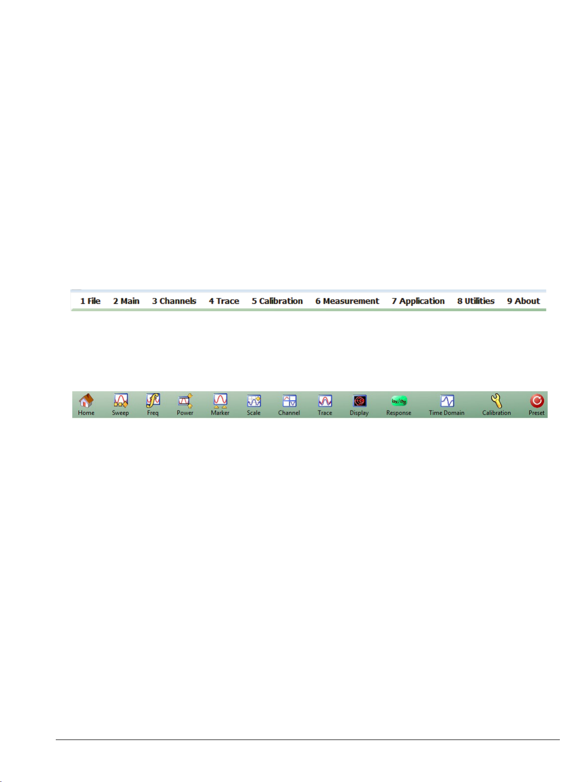
Chapter 2 — Menu Bar, Icon Bar, and Main Menu
2-1 Chapter Overview
This chapter describes the user interface screen layout, and navigation tools including the Menu Bar, Icon Bar,
and MAIN MENU.
Because the Menu Bar and Icon Bar are fully covered in the Operations Manual, these topics are only
summarized here. For full discussions, see the Operation Manual.
2-2 Menu Bar
The menu bar at the top of the screen provides drop-down menus for access to major ShockLine VNA functions
and dialogs. The bar is shown below.
2-3 Icon Bar
The icon toolbar is located immediately below the Menu Bar and allows single-click access to many menus and
functions. The icon toolbar is user-configurable and up to 20 icons can be displayed in any configuration.
MS46121A/B-122A/B-131A-322A/B Series UIRM PN: 10410-00337 Rev. AE 2-1
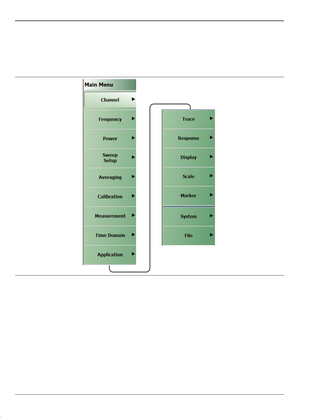
2-4 Main Menu Menu Bar, Icon Bar, and Main Menu
2-4 Main Menu
MAIN MENU
The MAIN MENU allows navigating to all functions of the software application. It is located at the right side of
the ShockLine screen. The split/collapsed view in the diagram below shows all of what is seen when the MAIN
MENU is scrolled down.
Figure 2-1. MAIN MENU – 2-Port VNAs
Channel
Selection displays the CHANNEL menu.
• “Channel Menus” on page 3-2
Frequency
Selection displays the FREQUENCY menu.
• “Overview of Frequency Menus” on page 4-1
Power
Select displays the POWER menu. 2-port VNAs only.
• “MS46322A/B Maximum and Minimum Power Settings” on page 5-1
2-2 PN: 10410-00337 Rev. AE MS46121A/B-122A/B-131A-322A/B Series UIRM

Menu Bar, Icon Bar, and Main Menu 2-4 Main Menu
Sweep Setup
Select displays the SWEEP SETUP menu.
• “Sweep Setup Menu” on page 6-2
Averaging
Select displays the AVERAGING menu.
• “Overview of the Averaging Menu” on page 7-1
Calibration
Select displays the CALIBRATION menu.
• “CALIBRATION [TR] Menu” on page 8-6
Measurement
Select displays the MEASUREMENT menu.
• “MEASUREMENT Menu” on page 9-3
Time Domain
Selection displays the TIME DOMAIN menu.
• Section 10-2 “Overview of the Time Domain Menu” on page 10-1
Application
Select displays the APPLICATION menu.
• “APPLICATION Menu (for Receiver Configuration)” on page 11-1
Tra ce
Select displays the TRACE menu.
• “TRACE Menu” on page 12-2
Response
Select displays the RESPONSE menu.
• “Response Menu” on page 13-3
Display
Select displays the DISPLAY menu.
• “DISPLAY Menu” on page 14-3
Scale
Select displays the SCALE menu which allows the user to change the scaling and other attributes of a trace
display.
• “Overview of Scale Menu Variants” on page 15-4
The available SCALE menu buttons change based on the settings on the DISPLAY Menu’s submenu TRACE
FORMAT.
• “TRACE FORMAT Menu” on page 14-8
MS46121A/B-122A/B-131A-322A/B Series UIRM PN: 10410-00337 Rev. AE 2-3

2-4 Main Menu Menu Bar, Icon Bar, and Main Menu
Marker
Select displays the MARKERS [1] menu.
• “MARKERS [1] Menu” on page 16-4
System
Select displays the SYSTEM menu.
• “SETUP Menu” on page 17-3
File
Select displays the FILE menu.
• “FILE Menu” on page 18-2
2-4 PN: 10410-00337 Rev. AE MS46121A/B-122A/B-131A-322A/B Series UIRM

Menu Bar, Icon Bar, and Main Menu 2-5 Context (Right-Click) Menus
2-5 Context (Right-Click) Menus
The ShockLine Series VNA provides three context menus, which can be accessed by right-clicking in the
designated areas:
• Main Display Area, Menu Bar, and Icon Toolbar
• Right-Side Menu
• Right-Side Menu Scroll Bar
Main Display Area, Menu Bar, and Icon Toolbar
• Context menu displays the Active Channel Number and Active Trace Number.
• The active channel’s Hold state is indicated by a check mark in the context menu.
• Right-clicking to activate the context menu will not change the active channel.
Figure 2-2. Main Display Area Context Menu
MS46121A/B-122A/B-131A-322A/B Series UIRM PN: 10410-00337 Rev. AE 2-5

2-5 Context (Right-Click) Menus Menu Bar, Icon Bar, and Main Menu
Right-Side Menu
• Context menu allows definition of up to five custom icon functions using the Right-side Menu context
menu. The actual icon symbols are predefined.
a. Click Set as Icon X to display the Custom Icon dialog.
Figure 2-3. Right-side Menu Context Menu—Initial State
b. Enter a Display Name of between 1 and 15 characters and click Save.
Figure 2-4. Custom Icon Dialog Box—Initial State
c. The custom icon will be added to the Icon Bar. The name of the selected custom icon will be
changed in both the Right-side Menu context menu and the Custom Icon dialog box. To move
the icon in the Icon Bar, use Customize Toolbar.
• If the Icon Bar is full, use Utilities | Customize Toolbar to adjust the number of icons in
the Icon Bar. The Customize Toolbar feature is described in the MS4632x Operation
Manual (10410-00335).
2-6 PN: 10410-00337 Rev. AE MS46121A/B-122A/B-131A-322A/B Series UIRM

Menu Bar, Icon Bar, and Main Menu 2-5 Context (Right-Click) Menus
Figure 2-5. Custom Icon Dialog Box and Icon Bar—E/O Meas. Icon Added
d. To redefine a custom icon, right-click the desired menu button and select the appropriate
icon entry in the Right-side Menu context menu. Enter new name, if desired, and click Save.
e. To deactivate a custom icon, right-click in the Right-side Menu context menu and select the
appropriate icon entry in the Right-side Menu context menu. In the Customize Icon dialog,
click Unlink. The custom icon will be removed from the Icon Bar. The name of the selected
custom icon will be changed to Set as Icon X in both the Right-side Menu context menu and
the Custom Icon dialog box.
Right-Side Menu Scroll Bar
• Available when right-side menu has extended content with a scroll-bar. Right-click in scroll bar.
Figure 2-6. Right-Side Menu Scroll Bar Context Menu
MS46121A/B-122A/B-131A-322A/B Series UIRM PN: 10410-00337 Rev. AE 2-7

2-5 Context (Right-Click) Menus Menu Bar, Icon Bar, and Main Menu
2-8 PN: 10410-00337 Rev. AE MS46121A/B-122A/B-131A-322A/B Series UIRM

Chapter 3 — Channel Menus
3-1 Chapter Overview
This chapter describes how to set the number of channels used and how they are displayed on the instrument.
Up to 16 channels can be configured, each with up to 16 traces per channel. For the MS46121A/B only, each
channel is dedicated to an individual 1-port VNA. Only those channels associated with VNA hardware will
have active trace displays.
3-2 Overview of Channel Menus
There are two channel menus:
• “CHANNEL Menu” on page 3-2
• “CHAN. LAYOUT Menu” on page 3-3
MS46121A/B-122A/B-131A-322A/B Series UIRM PN: 10410-00337 Rev. AE 3-1

3-3 Channel Menus Channel Menus
3-3 Channel Menus
The CHANNEL menu and the CHAN. LAYOUT menus are related in that the setting on one menu affects the
setting on the other menu.
CHANNEL Menu
Previous
• “Main Menu” on page 2-2
Navigation
• MAIN | Channel | CHANNEL
You can move between channels either by clicking on a channel on-screen, or from the keyboard by pressing
ALT and holding it, and pressing 3 followed by the menu number of the operation you want (such as 1 – Menu,
2 – Max, 3 – Previous, or 4 – Next).
Chan. Max
When multiple channels are displayed, use the Channel Maximum button to maximize
the active channel to fill the display area. Clicking a second time returns to the prior
multi-channel view.
Chan. Next
When multiple channels are displayed, the Channel Next button activates the next
higher channel number. When the highest channel number is reached, the next click
activates channel 1.
Chan. Previous
When multiple channels are displayed, the Channel Previous button activates the
next lower channel number. When channel 1 is reached, the next click activates the
highest channel number.
# of Channels
Select displays the Number of Channels field toolbar below the icon toolbar. The
toolbar allows the user to set the number of displayed channels in discrete values of 1
(one), 2, 3, 4, 6, 8, 9, 10, 12, or 16 channels. If other channel settings are applied (5, 7,
11, 13, 14, or 15), the instrument applies the next permitted channel setting. The
Channel Layout (described below) is automatically set to the number of selected
channels.
Chan. Layout
The Channel Layout button displays the CHAN. LAYOUT menu which defines how
multiple channels are displayed on the screen.
• “CHAN. LAYOUT Menu” on page 3-3
Figure 3-1. CHANNEL Menu
3-2 PN: 10410-00337 Rev. AE MS46121A/B-122A/B-131A-322A/B Series UIRM

Channel Menus 3-3 Channel Menus
CHAN. LAYOUT Menu
The CHANNEL LAYOUT menu allows the user to select from 22 selectable channel views. The channel view
buttons are not labeled, but instead provide a representative icon of each view configuration. For example, the
Single Channel View button provides a channel view where one channel is displayed in one display area. Once
the desired view is selected, click the Back button at the bottom of the CHAN. LAYOUT menu to return to the
CHANNEL menu. Note that CHAN. LAYOUT menu setting and the # of Channels setting on the CHANNEL menu
are linked. Changing the number of channels selects an appropriate channel layout. Changing the channel
layout where the number of displayed channels changes, changes the number of channels set on the CHANNEL
menu.
Full Name
• CHANNEL LAYOUT Menu
Previous
• “CHANNEL Menu” on page 3-2.
Navigation
• MAIN | Channel | CHANNEL | Chan. Layout | CHAN. LAYOUT
.
The Chan. Layout buttons do not have labels, but do have tool tips that appear if the mouse pointer
Note
The long CHAN LAYOUT menu is immediately below. The names of the different channel layout displays are
shown in the Table 3-1, “Channel Layout Options” on page 3-5 below.
is hovered over the button. The selected channel layout view is indicated by the button selected icon.
For VNA programmatic control, note also that each channel layout is described by the appropriate
SCPI parameter. For example, to program a three across channel layout, use the R1C3 parameter.
MS46121A/B-122A/B-131A-322A/B Series UIRM PN: 10410-00337 Rev. AE 3-3

3-3 Channel Menus Channel Menus
The menu uses the right-side scroll bar to display the entire menu.
Figure 3-2. CHAN. LAYOUT (CHANNEL LAYOUT) Menu
3-4 PN: 10410-00337 Rev. AE MS46121A/B-122A/B-131A-322A/B Series UIRM

Channel Menus 3-3 Channel Menus
The table below describes each Channel Layout option.
Table 3-1. Channel Layout Options (1 of 2)
Graphic Description
Single Channel View
Click Back to return to the CHANNEL menu.
R1C1 for SCPI programs.
Two Channel View – 2 Across x 1 Down
Click Back to return to the CHANNEL menu.
R1C2 for SCPI programs.
Two Channel View – 1 Across x 2 Down
Click Back to return to the CHANNEL menu.
R2C1 for SCPI programs.
Three Channel View – 3 Across
Click Back to return to the CHANNEL menu.
R1C3 for SCPI programs.
Three Channel View – 3 Down
Click Back to return to the CHANNEL menu.
R3C1 for SCPI programs.
Three Channel View – 2 on Top x 1 on Bottom
Click Back to return to the CHANNEL menu.
R2C2C1 for SCPI programs.
Three Channel View – 1 on Top x 2 on Bottom
Click Back to return to the CHANNEL menu.
R2C1C2 for SCPI programs.
Three Channel View – 2 on Left x 1 on Right
Click Back to return to the CHANNEL menu.
C2R2R1 for SCPI programs.
Three Channel View – 1 on Left x 2 on Right
Click Back to return to the CHANNEL menu.
C2R1R2 for SCPI programs.
Four Channel View – 4 Across
Click Back to return to the CHANNEL menu.
R1C4 for SCPI programs.
Four Channel View – 4 Down
Click Back to return to the CHANNEL menu.
R4C1 for SCPI programs.
Four Channel View – 2 Across x 2 Down
Click Back to return to the CHANNEL menu.
R2C2 for SCPI programs.
MS46121A/B-122A/B-131A-322A/B Series UIRM PN: 10410-00337 Rev. AE 3-5

3-3 Channel Menus Channel Menus
Tab le 3-1. Channel Layout Options (2 of 2)
Graphic Description
Six Channel View – 3 Across x 2 Down
Click Back to return to the CHANNEL menu.
R2C3 for SCPI programs.
Six Channel View – 2 Across x 3 Down
Click Back to return to the CHANNEL menu.
R3C2 for SCPI programs.
Eight Channel View – 4 Across x 2 Down
Click Back to return to the CHANNEL menu.
R2C4 for SCPI programs.
Eight Channel View – 2 Across x 4 Down
Click Back to return to the CHANNEL menu.
R4C2 for SCPI programs.
Nine Channel View – 3 Across x 3 Down
Click Back to return to the CHANNEL menu.
R3C3 for SCPI programs.
Ten Channel View – 5 Across x 2 Down
Click Back to return to the CHANNEL menu.
R5C2 for SCPI programs.
Ten Channel View – 2 Across x 5 Down
Click Back to return to the CHANNEL menu.
R2C5 for SCPI programs.
Twelve Channel View – 3 Across x 4 Down
Click Back to return to the CHANNEL menu.
R4C3 for SCPI programs.
Twelve Channel View – 4 Across x 3 Down
Click Back to return to the CHANNEL menu.
R3C4 for SCPI programs.
Sixteen Channel View – 4 Across x 4 Down
Click Back to return to the CHANNEL menu.
R4C4 for SCPI programs.
3-6 PN: 10410-00337 Rev. AE MS46121A/B-122A/B-131A-322A/B Series UIRM

Channel Menus 3-4 MS46121A/B Multi-Channel
3-4 MS46121A/B Multi-Channel
For the 1-port MS46212A/B VNA the CHANNEL menu and the CHAN. LAYOUT menus are related in that the
setting on one menu affects the setting on the other menu.
CHANNEL Menu
Previous
• “Main Menu” on page 2-2
Navigation
• MAIN | Channel | CHANNEL
You can move between channels either by clicking on a channel on-screen, or from the keyboard by pressing
ALT and holding it, and pressing 3 followed by the menu number of the operation you want (such as 1 – Menu,
2 – Max, 3 – Previous, or 4 – Next).
Chan. Max
When multiple channels are displayed, use the Channel Maximum button to maximize
the active channel to fill the display area. Clicking a second time returns to the prior
multi-channel view.
Chan. Next
When multiple channels are displayed, the Channel Next button activates the next
higher channel number. When the highest channel number is reached, the next click
activates channel 1.
Chan. Previous
When multiple channels are displayed, the Channel Previous button activates the
next lower channel number. When channel 1 is reached, the next click activates the
highest channel number.
Chan. Layout
The Channel Layout button displays the CHAN. LAYOUT menu.
Reconfigure
The Reconfigure button opens the CHANNEL RECONFIGURATION dialog that allows
the user to select channels for each 1 port MS46121A/B VNA, based on the device's
serial number.
Figure 3-3. MS46121A/B CHANNEL Menu
MS46121A/B-122A/B-131A-322A/B Series UIRM PN: 10410-00337 Rev. AE 3-7

3-4 MS46121A/B Multi-Channel Channel Menus
Reconfigure Dialog Box
The channel Reconfiguration allows the user to set multiple channels on each MS46121A/B device attached. A
maximum total of 16 channels can be set between all MS46121A/B devices.
Previous
• “CHANNEL Menu” on page 3-7
Navigation
• MAIN | Channel | CHANNEL | Reconfigure
Figure 3-4. SAVE (AUTOCAL CHARACTERIZATION/CAL) KIT FILE Dialog Box
Port
This provides the assignment of channels for a given device.
Device
This is the MS46121A/B device and is listed by serial number
NumOfChans
This field is used to add or delete the number of channels per device. When inputting NumOfChans, each entry
requires the user to press Enter on the keyboard or the value will reset to a default of 1.
3-8 PN: 10410-00337 Rev. AE MS46121A/B-122A/B-131A-322A/B Series UIRM

Chapter 4 — Frequency Menus
4-1 Chapter Overview
This chapter covers the FREQUENCY menu which allows the user to set frequency start, stop, span, number of
points, and CW mode parameters for the currently active (selected) channel. The FREQUENCY menu has
several variants; the one that is displayed depends on the Sweep Types setting for the current channel. The
sweep type is set on the SWEEP SETUP menu.
4-2 Overview of Frequency Menus
The appearance and content of the FREQUENCY menu and sub menus depend on the current channel’s sweep
mode, set by the SWEEP TYPES menu. The settings on the FREQUENCY menu apply to the currently active
channel.
The setup sequence is:
1. Select a channel
2. Select a sweep type for the channel.
See “SWEEP TYPES Menu” on page 6-5
• MAIN | Sweep Setup | SWEEP SETUP | Sweep Types | SWEEP TYPES
3. Set the channel’s frequency parameters on the FREQUENCY menu variant appropriate for your situation.
This chapter covers the sweep-based variants of the FREQUENCY menu. They are:
• “Frequency Menu for Frequency-Based Linear Sweep Mode” on page 4-2
• “Frequency Menu for Frequency-Based Logarithmic Sweep Mode” on page 4-4
• “Frequency Menu for Frequency-Based Segmented Sweep Mode” on page 4-5
• “Frequency Menu for Segmented Sweep (Index-Based) Mode” on page 4-7
MS46121A/B-122A/B-131A-322A/B Series UIRM PN: 10410-00337 Rev. AE 4-1

4-3 Frequency Menu for Frequency-Based Linear Sweep Mode Frequency Menus
4-3 Frequency Menu for Frequency-Based Linear Sweep Mode
Function(s)
This menu controls linear sweeps.
Displays
• Traces for the channel will show linear axes.
Prerequisites
• User has selected a channel to set up.
• This menu is enabled by selection of Frequency Sweep on the SWEEP TYPES menu.
Navigation
• MAIN | Frequency | FREQUENCY
Appearance and Controls
Start (Frequency)
Displays the Start (Frequency) field toolbar and allows the user to enter a starting
frequency.
Stop (Frequency)
Displays the Stop (Frequency) field toolbar and allows the user to enter a stop
frequency.
Center (Frequency)
The Center (Frequency) button displays the Center (Frequency) field toolbar and
allows the user to enter a center frequency.
Span (Frequency)
The Span (Frequency) button displays the Span (Frequency) field toolbar and allows
the user to enter a span frequency.
# of Points
The Number of Points button displays the # of Points field toolbar and allows the user
to enter the number of points for the frequency span, allowing separate parameter
point settings for CW Mode ON and CW Mode OFF.
Figure 4-1. FREQUENCY Freq. Based Sweep Menu (1 of 2)
4-2 PN: 10410-00337 Rev. AE MS46121A/B-122A/B-131A-322A/B Series UIRM

Frequency Menus 4-3 Frequency Menu for Frequency-Based Linear Sweep Mode
Step Size (Frequency)
This read-only field displays the frequency step-size computed from the requested
frequency span and the number of points selected in the buttons above. If the CW
Mode (below) is set to ON, the read-only field displays 0 (zero) Hz.
CW Mode (Off/On)
The Continuous Wave (CW) toggle button toggles the CW function off and on. The
default setting is OFF. If CW Mode is ON, the Step Size (Frequency) display
(described above) is set to 0 (zero) Hz and the # of Points setting changes to what has
been set for the CW Mode.
CW Frequency
The CW Frequency button displays the CW Frequency field toolbar and allows the
user to set the required CW frequency. Input the required frequency value and select
GHz, MHz, kHz, or Hz. If a calibration is active, the VNA will choose the closest CW
frequency point from the active calibration points. If the requested CW frequency is a
calibrated point, the VNA will assign the entered value. Note that the CW Frequency
must fall within the range set by the Start/Stop buttons above.
Figure 4-1. FREQUENCY Freq. Based Sweep Menu (2 of 2)
MS46121A/B-122A/B-131A-322A/B Series UIRM PN: 10410-00337 Rev. AE 4-3

4-4 Frequency Menu for Frequency-Based Logarithmic Sweep Mode Frequency Menus
4-4 Frequency Menu for Frequency-Based Logarithmic Sweep Mode
Function(s)
This menu controls logarithmic sweeps.
Displays
• Traces for the channel will show logarithmic axes.
Prerequisites
• User has selected a channel to set up.
• This menu is enabled by selection of Frequency Sweep (Log) on the SWEEP SETUP menu’s SWEEP
TYPES button.
Navigation
• MAIN | Frequency | FREQUENCY
Appearance and Controls
The menu appearance and controls are exactly the same as for Frequency-Based Linear Sweep shown in
“Frequency Menu for Frequency-Based Linear Sweep Mode” on page 4-2. Traces appear the same except that
the graph bars are logarithmic.
4-4 PN: 10410-00337 Rev. AE MS46121A/B-122A/B-131A-322A/B Series UIRM

Frequency Menus 4-5 Frequency Menu for Frequency-Based Segmented Sweep Mode
4-5 Frequency Menu for Frequency-Based Segmented Sweep Mode
Function(s)
This menu controls frequency-based segmented sweeps. (Parameters are also set at the SWEEP SETUP menu’s
Freq-based Seg. Sweep Setup button and its menu.)
Displays
• Traces for the channel will show linear axes.
Prerequisites
• User has selected a channel to set up.
• This menu is enabled by selection of Segmented (Freq) sweep type on the SWEEP SETUP menu’s Sweep
Types button.
Navigation
• MAIN | Frequency | FREQUENCY
Appearance and Controls
• The three active buttons are Start Range, Stop Range, and Maximize Range
• The three read-only buttons are Display Start, Display Stop, and DataPoints.
Start Range (Frequency)
Select displays the Start Range (Frequency) toolbar with frequency values and units
of GHz, MHz, kHz, and Hz.
Stop Range (Frequency)
Select displays the Stop Range (Frequency) toolbar with frequency values and units
of GHz, MHz, kHz, and Hz.
Maximize Range (Frequency)
Select maximizes the start and stop value to the maximum of the instrument. Note
that when clicked, any previously entered Start and Stop value are overwritten and
cannot be recovered unless a preset save was done.
Display Start (Frequency)
A read-only display of the Start Range frequency.
Display Stop (Frequency)
A read-only display of the Stop Range frequency.
Figure 4-2. FREQUENCY Freq. Based Segmented Sweep Menu (1 of 2)
MS46121A/B-122A/B-131A-322A/B Series UIRM PN: 10410-00337 Rev. AE 4-5

4-5 Frequency Menu for Frequency-Based Segmented Sweep Mode Frequency Menus
DataPoints (Number)
A read-only display of the calculated number of data points in the set frequency
range.
Figure 4-2. FREQUENCY Freq. Based Segmented Sweep Menu (2 of 2)
4-6 PN: 10410-00337 Rev. AE MS46121A/B-122A/B-131A-322A/B Series UIRM

Frequency Menus 4-6 Frequency Menu for Segmented Sweep (Index-Based) Mode
4-6 Frequency Menu for Segmented Sweep (Index-Based) Mode
Function(s)
This menu controls index-based segmented sweeps. (Parameters are also set at the SWEEP SETUP Menu’s
Index-based Seg. Sweep Setup button and its menu.)
Displays
Sweeps showing index-based data.
Prerequisites
• User has selected a channel to set up.
• This menu is available when Segmented Sweep (Index-based) is selected on the SWEEP TYPES menu’s
Sweep Types button.
Navigation
• MAIN | Frequency | FREQUENCY
Appearance
• The three (3) active buttons are Start Index, Stop Index, and Maximize Range
• The three read-only buttons are Display Start Index, Display Stop Index, and DataPoints
Start Index (Number)
Select displays the Start (Index Number) toolbar allowing the selection of a starting
index number for the sweep.
Stop Index (Number)
Select displays the Stop (Index Number) toolbar allowing the selection of an ending
index number for the sweep.
Maximize Range
Select maximizes the start and stop value to the maximum of the instrument. Note
that when clicked, any previously entered Start and Stop values are overwritten and
cannot be recovered unless a preset save was done.
Display Start Index (Number)
A read-only display of the Start Index number.
Figure 4-3. INDEX. SEG. SWP (FREQUENCY) Index-Based Segmented Sweep Menu (1 of 2)
MS46121A/B-122A/B-131A-322A/B Series UIRM PN: 10410-00337 Rev. AE 4-7

4-6 Frequency Menu for Segmented Sweep (Index-Based) Mode Frequency Menus
Display Stop Index (Number)
A read-only display of the Stop Index number.
DataPoints (Number)
A read-only display of the calculated number of data points in the swept frequency
range.
Figure 4-3. INDEX. SEG. SWP (FREQUENCY) Index-Based Segmented Sweep Menu (2 of 2)
4-8 PN: 10410-00337 Rev. AE MS46121A/B-122A/B-131A-322A/B Series UIRM

Chapter 5 — Power Menus
5-1 Chapter Overview
This chapter provides information on port power control in MS461xx series and MS463xx series VNAs. Power
conditions for sweeps are set in different places in the ShockLine application, depending on the sweep type:
1) for frequency-based sweeps, the POWER menu is used to set power parameters, and 2) for segmented and
indexed sweeps, the power setup controls are in segment or index setup characteristics areas of the sweep table
(see Chapter 6 — Sweep Menus for details).
Note
The MS46121A/B 1-port VNA has only one default power level, so the power menu is not applicable
and not available.
MS46322A/B Maximum and Minimum Power Settings
The VNAs in the MS46322A/B series support using one of two power levels—High or Low—in normal use.
For all configurations, the maximum power setting is High.
Table 5-1 below shows values for the two standard power settings.
Table 5-1. Summary of Standard Maximum and Minimum Power Levels
Output Power
VNA Power Level Power Setting
MS46322A-004
MS46322A/B-010
MS46322A-014
MS46322A/B-020
MS46322A-030
MS46322A/B-040
MS46322B-043
Maximum Power High -3 dBm
Minimum Power Low -20 dBm
(Typical)
MS46122A/B Maximum and Minimum Power Settings
The VNAs in the MS46122A/B series support using one of two power levels—High or Low—in normal use.
For all configurations, the maximum power setting is High.
Table 5-2 below shows values for the two standard power settings.
Table 5-2. Summary of Standard Maximum and Minimum Power Levels
Output Power
VNA Power Level Power Setting
MS46122A/B-010
MS46122A/B-020
MS46122A/B-040
MS46122B-043
MS46121A/B-122A/B-131A-322A/B Series UIRM PN: 10410-00337 Rev. AE 5-1
Maximum Power High -3 dBm
Minimum Power Low -20 dBm
(Typical)

5-2 Overview – Power Menus Power Menus
MS46131A Maximum and Minimum Power Settings
The VNAs in the MS46131A series support using one of two power levels—High or Low—in normal use. High
and low settings also apply to the ME7868A 2-port VNA systems.
For all configurations, the maximum power setting is High.
Table 5-3 below shows values for the two standard power settings.
Tab le 5-3. Summary of Standard Maximum and Minimum Power Levels
Output Power
VNA Power Level Power Setting
(Typical)
MS46131A-010
MS46131A-020
MS46131A-043
Maximum Power High 0 dBm
Minimum Power Low -20 dBm
5-2 Overview – Power Menus
Locations of Power Settings
There are two main things to know about the VNA power controls:
1. The sweep type determines where the power controls are found. For basic frequency-based sweeps the
controls are in the POWER menus. For segment or index sweeps, the controls are both in the POWER
menus and in SWEEP menu setup tables.
2. The POWER menu contents such as menu title text, buttons, and available functions, may vary
depending on selected sweep type, instrument model, and installed options.
This chapter organizes discusses of POWER menus by sections reflecting the sweep type. The following is a
quick reference:
1. POWER Settings for Frequency-Based Sweeps
If SWEEP Menu SWEEP TYPES is set to either Frequency Sweep (for linear sweep) or to Frequency Sweep
(Log), the power settings are under the POWER menu and its submenus.
2. POWER Settings for Segment-Based Sweeps
If SWEEP Menu SWEEP TYPES is set to a Segment-Based Sweep type (Frequency or Index), the per-port
power and effective power are set on a per-segment basis in the Segmented Sweep Setup Tableau dialog area.
To reach that dialog:
How to Navigate to Power Settings for Frequency-Segment-Based Sweeps
• MAIN | Sweep Setup | SWEEP SETUP | Freq-Based Seg Sweep Setup | FREQ BASE SETUP
• For use see “FREQ BASE SETUP Menu” on page 6-6
How to Navigate to Power Settings for Index-Based Segmented Sweeps
• MAIN | Sweep Setup | SWEEP SETUP | Index-Based Seg Sweep Setup | INDEX BASE SETUP
• For use see “INDEX BASE SETUP Menu” on page 6-12
5-2 PN: 10410-00337 Rev. AE MS46121A/B-122A/B-131A-322A/B Series UIRM

Power Menus 5-2 Overview – Power Menus
Power Coupling State Is Shown in Power Menu Titles
• POWER menu title text of ‘POWER [COUPLED]’ or ‘POWER [C]’ indicates that all port powers are
coupled.
• POWER menu title text of ‘POWER’ indicates that the port powers are not coupled.
MS46121A/B-122A/B-131A-322A/B Series UIRM PN: 10410-00337 Rev. AE 5-3

5-3 Power Menu for Frequency-Based Sweeps (Linear or Log) Power Menus
5-3 Power Menu for Frequency-Based Sweeps (Linear or Log)
Navigation
• MAIN | Power | POWER
POWER Menu
The menu title dynamically changes to show whether the port power levels are
coupled or not
Other Setup
Selection opens the POWER SETUP dialog. (See description of MIN. PORT POWER
below.) When Sweep Type is Segmented (Frequency or Indexed), this capability is
not available and the button is deactivated and grayed out.
Low Power
Selection applies the Low Power setting to both ports for sweeps on the current
channel.
High Power
Selection applies the High Power setting to both ports for sweeps on the current
channel.
Figure 5-1. POWER Menu – Frequency-Based Sweep Modes – MS46122A/B and MS46322A/B 2-Port VNAs
Power Setup Menu
Min. Port Power Dialog
This dialog has one button for on/off control of minimum power on the ports. When
set ON, the VNA will use the lowest output power it can achieve. (This is not the
same as the Low Power setting, which simply applies the normal Low Power setting
in sweeps.
Figure 5-2. POWER Setup Menu – Frequency-Based Sweep Modes – MS46122A/B and MS46322A/B 2-Port
VNAs
5-4 PN: 10410-00337 Rev. AE MS46121A/B-122A/B-131A-322A/B Series UIRM

Power Menus 5-3 Power Menu for Frequency-Based Sweeps (Linear or Log)
Power Menu (MS46131A 2-Port VNAs)
POWER Menu
Power Coupling
Power Coupling is set to ON.
Port Selection
Set to Port 1 to select High or Low Power Coupling.
Low Power
Selection applies the Low Power setting to both ports for sweeps on the current
channel.
High Power
Selection applies the High Power setting to both ports for sweeps on the current
channel.
Figure 5-3. POWER Menu – Frequency-Based Sweep Modes – MS46131A 2-Port VNAs
Power Menu (MS46131A 1-Port VNAs)
POWER Menu
Port Selection
Set to Port 1. Button is deactivated.
Low Power
Selection applies the Low Power setting to both ports for sweeps on the current
channel.
High Power
Selection applies the High Power setting to both ports for sweeps on the current
channel.
Figure 5-4. POWER Menu – Frequency-Based Sweep Modes – MS46131A 1-Port VNAs
MS46121A/B-122A/B-131A-322A/B Series UIRM PN: 10410-00337 Rev. AE 5-5

5-4 Power Menu for Segment-Based Sweeps – 2-Port VNAs Power Menus
5-4 Power Menu for Segment-Based Sweeps – 2-Port VNAs
Previous
• “Main Menu” on page 2-2
Navigation
• MAIN | Power | POWER
Prerequisites
• SWEEP TYPES = Frequency-Based Segmented Sweep or Index-Based Segmented Sweep
• Segmented Sweep Frequency-Based Setup
• MAIN | Sweep Setup | SWEEP SETUP | Sweep Type | SWEEP TYPES | Segmented Sweep
(Freq-Based)
• “SWEEP SETUP Menu — MS46122A/B and MS46322A/B Series” on page 6-2
• SWEEP TYPES – Segmented Sweep Index-Based Setup
• MAIN | Sweep Setup | SWEEP SETUP | Sweep Type | SWEEP TYPES | Segmented Sweep
(Index-Based)
• “SWEEP SETUP Menu — MS46122A/B and MS46322A/B Series” on page 6-2
POWER Menu
The menu title dynamically changes to show whether the port power levels are
coupled or not.
Other Setup (Power)
OTHER SETUP is not available, nor applicable, under this sweep mode.
Low Power
Selection applies the Low Power setting to both ports for sweeps on the current
channel.
High Power
Selection applies the High Power setting to both ports for sweeps on the current
channel.
Figure 5-5. POWER Menu – Segment-Based Sweep – 2-Port VNAs
5-6 PN: 10410-00337 Rev. AE MS46121A/B-122A/B-131A-322A/B Series UIRM

Chapter 6 — Sweep Menus
6-1 Chapter Overview
This chapter describes sweep types supported by the VNA and how to set and configure them.
6-2 Sweep on the ShockLine VNA
The SWEEP menu is used to select sweep type for a channel, and to set key sweep parameters. You can choose
from these types:
A. Basic (continuous) frequency sweeps:
• Frequency-based (linear) sweep–you can set start and end frequency values for the sweep. All traces in
the display have linear frequency axes.
• Frequency-based (logarithmic) sweep–you can set start and end frequency values for the sweep. All
traces in the display have logarithmic frequency axes
This sweep type is configured for frequency on the Frequency menu and port power is set at the Power menu.
B. Segmented frequency sweeps:
• Segmented frequency-based sweep—you can create multiple linear segments each with its own
independent start and end frequencies.
• Segmented index-based sweep—you can create a collection of index-based specific frequencies that the
instrument steps through. Any index point can have any frequency assigned.
Segments for these sweep types are configured through the SWEEP SETUP menu. Segment parameters for
frequency, power, and number of points are set on the SWEEP SETUP tableau at the bottom of the display
window. You can also set parameters for segments at the FREQUENCY menu.
In all cases, the Sweep Type selected for a channel applies to all traces of that channel.
All sweep configurations can be saved or recalled individually and/or can be assigned to a user-defined preset
setup configuration. The configuration can be recalled at any time. You can configure the hold and trigger
conditions for a sweep type.
6-3 Overview of Sweep Menus
These are the sweep control menus and dialog boxes:
• “SWEEP SETUP Menu — MS46122A/B and MS46322A/B Series” on page 6-2
• “SWEEP SETUP Menu — MS46131A Series” on page 6-3
• “FREQ BASE SETUP Menu” on page 6-6
• “SEGMENTED SWEEP DEFINITION Table” on page 6-8
• “SAVE AS (SEGMENT SWEEP TABLE SGS FILE) Dialog Box” on page 6-10
• “RECALL SEGMENTED SWEEP TABLE SGS FILE Dialog Box” on page 6-11
• “INDEX BASE SETUP Menu” on page 6-12
• “HOLD FUNCTIONS Menu” on page 6-13
• “TRIGGER Menu” on page 6-15
• “TRIGGER SOURCE Menu” on page 6-16
• “EXT. TRIGGER Menu” on page 6-16
MS46121A/B-122A/B-131A-322A/B Series UIRM PN: 10410-00337 Rev. AE 6-1

6-4 Sweep Setup Menu Sweep Menus
6-4 Sweep Setup Menu
SWEEP SETUP Menu — MS46122A/B and MS46322A/B Series
Purposes
• Select sweep type, and set up sweep parameters.
Navigation
• MAIN | Sweep Setup | SWEEP SETUP
Sweep Types
Selecting displays the SWEEP TYPES menu for selection frequency sweep options.
The display field in the Sweep Types button displays the instrument sweep setting
for the active channel. The possible field display values and their meanings are:
• Frequency Sweep – linear sweep from start to stop frequency
• Frequency Sweep (Log) – logarithmic sweep from start to stop frequency
• Segmented Sweep (Freq-based) – sweep using frequency-based segments
• Segmented (Index) – index-based segmented sweep
Freq-Based Seg Sweep Setup
Selecting displays the FREQ BASE SETUP menu and opens the FREQ DEF for F1 &
F2 tableau area below the main display area.
• “FREQ BASE SETUP Menu” on page 6-6
Index-Based Seg Sweep Setup
Selecting displays the INDEX BASE SETUP menu and opens the FREQ DEF for F1 &
F2 table area below the main display area.
• “INDEX BASE SETUP Menu” on page 6-12
Hold Functions
Selecting displays the HOLD FUNCTIONS menu.
• “HOLD FUNCTIONS Menu” on page 6-13
Trigger
Selecting displays the TRIGGER menu.
• “TRIGGER Menu” on page 6-15
Figure 6-1. SWEEP SETUP Menu – MS46122A/B and MS46322A/B Series
6-2 PN: 10410-00337 Rev. AE MS46121A/B-122A/B-131A-322A/B Series UIRM

Sweep Menus 6-4 Sweep Setup Menu
SWEEP SETUP Menu — MS46131A Series
Purposes
• Select sweep type, and set up sweep parameters.
Navigation
• MAIN | Sweep Setup | SWEEP SETUP
With Option 012
Sweep Types
Selecting displays the SWEEP TYPES menu for selection frequency sweep options.
The display field in the Sweep Types button displays the instrument sweep setting
for the active channel. The possible field display values and their meanings are:
• Frequency Sweep – linear sweep from start to stop frequency
• Frequency Sweep (Log) – logarithmic sweep from start to stop frequency
• Segmented Sweep (Freq-based) – sweep using frequency-based segments
• Segmented (Index) – index-based segmented sweep
Freq-Based Seg Sweep Setup
Selecting displays the FREQ BASE SETUP menu and opens the FREQ DEF for F1 &
F2 tableau area below the main display area.
• “FREQ BASE SETUP Menu” on page 6-6
Index-Based Seg Sweep Setup
Selecting displays the INDEX BASE SETUP menu and opens the FREQ DEF for F1 &
F2 table area below the main display area.
• “INDEX BASE SETUP Menu” on page 6-12
Hold Functions
Selecting displays the HOLD FUNCTIONS menu.
• “HOLD FUNCTIONS Menu” on page 6-13
Trigge r
Selecting displays the TRIGGER menu.
• “TRIGGER Menu” on page 6-15
High Isolation Mode (MS46131A Option 012 only)
The High Isolation Mode button will only be present if two or more MS46131A VNAs
with PhaseLync™ (Option 12) active are connected.
If a calibration exists and is on, the High Isolation Mode state cannot be changed,
and the button will be disabled.
Figure 6-2. SWEEP SETUP Menu – MS46131A Series (1 of 2)
MS46121A/B-122A/B-131A-322A/B Series UIRM PN: 10410-00337 Rev. AE 6-3

6-4 Sweep Setup Menu Sweep Menus
Without Option 012
Parallel Sweep (Two MS46131A VNAs only)
The Parallel Sweep button will only be visible if two or more MS46131A VNAs are
connected.
If there is a trace display set to a transmission response (i.e., S12, S21), the parallel
sweep button will be disabled.
If parallel sweep is turned on, then user cannot change the response of any trace to
transmission type.
Figure 6-2. SWEEP SETUP Menu – MS46131A Series (2 of 2)
6-4 PN: 10410-00337 Rev. AE MS46121A/B-122A/B-131A-322A/B Series UIRM

Sweep Menus 6-4 Sweep Setup Menu
SWEEP TYPES Menu
Purposes
• Select sweep type.
Navigation
• MAIN | Sweep Setup | SWEEP SETUP | Sweep Types | SWEEP TYPES
Notes
Several classes of sweep type appear here, invoked by control buttons:
• linear or log frequency sweep
• segmented sweep (either normal segments each with a start and end frequency, or indexed segments
each having a start and end frequency)
Segmented Sweep: Introduction
Segmented Sweep allows selections of different frequency segments, each monotonic in frequency, and where
each segment can have a different number of points, power level, and Averaging. There are two types of
segmented sweep. In the frequency-based version, segments can have many points in a short segment or no
points within a long segment. In index based, the sweep has all points are plotted with equal spacing, and any
point can have any frequency
Frequency Sweep
Sets the sweep type to a linear function. The displayed X-axis is linear. Sweep
frequency parameters are set at the FREQUENCY menu.
Frequency Sweep (Log)
Sets the sweep type to a log function. Log sweeps have unequal step sizes and the
number of points selected are spread equally between the decade divisions, and are
displayed on a log scale X-axis. Sweep frequency parameters are set at the
FREQUENCY menu.
Segmented Sweep (Freq-Based)
Sets the sweep type to a frequency segment-based sweep. The displayed x-axis is
linear and the frequencies are plotted where those frequencies lie. Sweep frequency
parameters are set using the SEGMENTED SWEEP DEFINITION table dialog that
appears below the main display when in this mode.
Segmented Sweep (Index-Based)
Sets the sweep type to an index-based segmented sweep and de-selects all other
sweep types. Sweep frequency parameters are set using the SEGMENTED SWEEP
DEFINITION table dialog that appears below the main display when in this mode. An
index-based segmented sweep sweeps over a custom list of frequency points. The
indexed frequencies do not have to be in any order. Plotting on the X-axis is
index-based and not frequency based, and index points are shown in order on the
axis, displayed at equal spacing. The frequencies in each segment do not have to be
monotonic. Index-based sweeps are often used when reverse sweeps and a particular
frequency order is required. If index-based segmented sweep is selected, the display
mode for all traces if the channel is always limited to index-based.
Figure 6-3. SWEEP TYPES Menu
MS46121A/B-122A/B-131A-322A/B Series UIRM PN: 10410-00337 Rev. AE 6-5

6-5 Frequency-Based Segmented Sweep Setup Sweep Menus
6-5 Frequency-Based Segmented Sweep Setup
FREQ BASE SETUP Menu
Purposes
• Used to set up frequency-based segment sweep parameters.
Navigation
• MAIN | Sweep Setup | SWEEP SETUP | Freq-Based Seg Sweep Setup | FREQ BASE SETUP
Notes
When the FREQ BASE SETUP menu appears, the companion set of controls, SEGMENTED SWEEP
DEFINITION table dialog, also appears. The table display at the bottom of the main display area allows the
configuration of frequency segments for sweep management. See instructions in “SEGMENTED SWEEP
DEFINITION Table” on page 6-8.
Graph Mode (Freq Base/Index Base)
Toggles graph mode between Freq Base and Index Base. When Freq Base is selected,
the display status bar shows Freq Base.
Display IFBW (Off/On)
Toggles the IFBW column off and on. If ON, the IFBW field is added to the Freq Def.
for F1 & F2 table header in the SEGMENTED SWEEP DEFINITION table below.
Display Power (Off/On)
Toggles the Power column display off and on. If ON, the P1 Src. Pwr (Src. Atten – 0
dB) and P2 Src. Pwr (Src. Atten – 0 dB) columns are added to the Freq Def. for F1 & F2
table header in the SEGMENTED SWEEP DEFINITION table.
Display Averaging (Off/On)
Toggles the Averaging column display off and on. If ON, the Averaging field is added
to the Freq Def. for F1 & F2 table header in the SEGMENTED SWEEP DEFINITION
table.
Add (Freq-Based Segment)
Adds a row for a new segment to the FREQ DEF. FOR F1 & F2 table information
below the currently selected segment.
Delete (Freq-Based Segment)
Deletes the currently selected row/segment from the FREQ DEF. FOR F1 & F2 table
information.
Clear All Segments (Freq-Based Segment)
Clears all rows except for Row 1 from the FREQ DEF. FOR F1 & F2 table information.
Figure 6-4. FREQ BASE SETUP (FREQUENCY-BASED SEGMENTED SWEEP SETUP) Menu (1 of 2)
6-6 PN: 10410-00337 Rev. AE MS46121A/B-122A/B-131A-322A/B Series UIRM

Sweep Menus 6-5 Frequency-Based Segmented Sweep Setup
Save Table to File (Freq-Based Segment)
Saves the table data to a Segment Sweep .sgs file. Select displays the SAVE
SEGMENTED SWEEP Table (SGS File) dialog box.
• “SAVE AS (SEGMENT SWEEP TABLE SGS FILE) Dialog Box” on page 6-10
Recall Table from File (Freq-Based Segment)
Recalls table data from a Segment Sweep .sgs file. Select displays the RECALL
SEGMENTED SWEEP TABLE (Sweep SGS File) dialog box.
• “RECALL SEGMENTED SWEEP TABLE SGS FILE Dialog Box” on page 6-11
Figure 6-4. FREQ BASE SETUP (FREQUENCY-BASED SEGMENTED SWEEP SETUP) Menu (2 of 2)
MS46121A/B-122A/B-131A-322A/B Series UIRM PN: 10410-00337 Rev. AE 6-7

6-5 Frequency-Based Segmented Sweep Setup Sweep Menus
SEGMENTED SWEEP DEFINITION Table
Purposes
Used to edit frequency-based segment sweep parameters.
Navigation
• MAIN | Sweep Setup | SWEEP SETUP | Freq-Based Seg Sweep Setup | FREQ BASE SETUP
Overview
The FREQ DEF. FOR F1 and F2 (Segmented Sweep Definition) table information appears below the display
area. The number of rows and columns displayed depend on the button settings in the Freq Base Setup menu.
The default settings display the following column fields: IFBW, P1 source power, P2 source power, and
Averaging.
Default Appearance
The following table displays all possible fields.
Freq Def. for F1 & F2 Column, Sweep Segment Options Pull-Down Menu
The FREQ DEF. FOR F1 & F2 pull-down menu allows each segments to be set as either a Stop & Start, Start &
Step Size, or CW (F2 not used).
Display IFBW Column, Toggle Off/On
The Display IFBW button on the FREQ BASE SETUP menu causes the IFBW column to disappear and appear.
Display Power Column, Toggle Off/On
The Display Power button on the FREQ BASE SETUP menu causes the Power columns to disappear and
appear.
Display Averaging, Toggle Off/On
The Display Averaging button on the FREQ BASE SETUP menu causes the Averaging column to disappear and
appear.
6-8 PN: 10410-00337 Rev. AE MS46121A/B-122A/B-131A-322A/B Series UIRM

Sweep Menus 6-5 Frequency-Based Segmented Sweep Setup
Adding Rows
Selecting the Add button on the FREQ BASE SETUP menu adds a row to the tableau so that another frequency
segment can be added.
To add additional rows, repeat selecting the Add button. Note that the currently selected and editable row is
indicated by the left arrow, as shown in Row 3 below.
Deleting Rows
Select a row to delete it. A selected row is indicated by the right-facing arrow icon as shown for Row 2 below:
Click the Delete button on the FREQ BASE SETUP menu to delete the row:
Click the Clear All Seg. button on the FREQ BASE SETUP menu to clear all rows.
MS46121A/B-122A/B-131A-322A/B Series UIRM PN: 10410-00337 Rev. AE 6-9

6-5 Frequency-Based Segmented Sweep Setup Sweep Menus
SAVE AS (SEGMENT SWEEP TABLE SGS FILE) Dialog Box
Purposes
• Used to save the frequency-based segment sweep table.
Navigation
• MAIN | Sweep Setup | SWEEP SETUP | Freq-Based Seg Sweep Setup | FREQ BASE SETUP | Save Table to
File | SAVE SEGMENTED SWEEP TABLE Dialog Box
Figure 6-5. SAVE AS (SEGMENT SWEEP TABLE SGS FILE) Dialog Box
Instructions
Navigate to required location, enter unique file name, and click Save. Click Cancel to return to the FREQ BASE
SETUP menu.
6-10 PN: 10410-00337 Rev. AE MS46121A/B-122A/B-131A-322A/B Series UIRM

Sweep Menus 6-5 Frequency-Based Segmented Sweep Setup
RECALL SEGMENTED SWEEP TABLE SGS FILE Dialog Box
Purposes
• Used to load and use a frequency-based segment sweep table.
Navigation
• MAIN | Sweep Setup | SWEEP SETUP | Freq-Based Seg Sweep Setup | FREQ BASE SETUP | Recall Table
from File | RECALL SEGMENTED SWEEP TABLE SGS FILE Dialog Box
Figure 6-6. RECALL (SEGMENTED SWEEP TABLE SGS FILE) Dialog Box
Instructions
Navigate to required location, select the required SGS file, and click Open. Click Cancel to return to the FREQ
BASE SETUP menu.
MS46121A/B-122A/B-131A-322A/B Series UIRM PN: 10410-00337 Rev. AE 6-11

6-6 Index-Based Segmented Sweep Setup Sweep Menus
6-6 Index-Based Segmented Sweep Setup
INDEX BASE SETUP Menu
Purposes
Used to set up index-based segment sweep parameters.
Navigation
• MAIN | Sweep Setup | SWEEP SETUP | Index-Based Seg Sweep Setup | INDEX BASE SETUP
Notes
When the INDEX BASE SETUP menu appears, the companion set of controls, SEGMENTED SWEEP
DEFINITION TABLE dialog, also appears. The table display at the bottom of the main display area. allows the
configuration of frequency segments for sweep management. For Add, Delete, and Clear, see instructions in
“SEGMENTED SWEEP DEFINITION Table” on page 6-8.
Display IFBW (Off/On)
Toggles the IFBW column ff and on in the tableau display. If ON, the IFBW column
field is added to the Freq Def. for F1 & F2 table header.
Display Power (Off/On)
Toggles the P1 Src. Pwr and P2 Src. Pwr columns off and on in the tableau display
Display Averaging (Off/On)
Toggles the Averaging column display off and on in the tableau display. If ON, an
Averaging column field is added to the Freq Def. for F1 & F2 table header.
Add (Index-Based Segment)
Adds a row to the FREQ DEF. FOR F1 & F2 table information in the tableau area.
Delete (Index-Based Segment)
To delete a row in the tableau, select a row there so the Right Arrow icon appears.
Click Delete to remove the row from the FREQ DEF. FOR F1 & F2 table information.
Clear All Segments (Index-Based Segment)
To clear all rows in the tableau area, select the Clear All Segments button. This clears
all rows except for Row 1 from the FREQ DEF. FOR F1 & F2 table information.
Save Table to File (Index-Based Segment)
This displays the Save Segmented Sweep Table (SGS File) dialog box to save the
segment table data as a Segment Sweep SGS file.
• “SAVE AS (SEGMENT SWEEP TABLE SGS FILE) Dialog Box” on page 6-10
Recall Table from File (Index-Based Segment)
This displays the RECALL SEGMENTED SWEEP TABLE (SGS) dialog box to recall
table data from a previously stored Segment Sweep SGS file.
• “RECALL SEGMENTED SWEEP TABLE SGS FILE Dialog Box” on page 6-11
Figure 6-7. INDEX BASE SETUP (INDEX-BASED SEGMENTED SWEEP SETUP) Menu
6-12 PN: 10410-00337 Rev. AE MS46121A/B-122A/B-131A-322A/B Series UIRM

Sweep Menus 6-7 Sweep Hold and Trigger Functions
6-7 Sweep Hold and Trigger Functions
HOLD FUNCTIONS Menu
Purposes
Provides hold control over sweep in the current display channel.
Navigation
• MAIN | Sweep Setup | SWEEP SETUP | Hold Functions | HOLD FUNCTIONS
HOLD FUNCTIONS Menu – Button Selection Group
The top three buttons of the HOLD FUNCTIONS menu provide hold control for the
active channel.
The Hold, Sweep, and Single Sweep & Hold buttons form a three button selection
group where the selection of any one button de-selects the other two buttons.
The fourth button, Hold Conditions, opens the menu for setting hold conditions.
Hold
The Hold button pauses the display and stops the channel signal processing.
Sweep
The Sweep button starts signal processing and resumes the active channel display.
Single Sweep & Hold
For the active channel, the Single Sweep & Hold button performs a single sweep
signal processing, and then holds the display, stops signal processing, and returns
the button selection to the Hold button.
Hold All Channels
The Hold button pauses the display and stops the signal processing on all channels.
Sweep All Channels
The Sweep button starts the signal processing and resumes all channel displays.
Single Sweep & Hold All Channels
For all channels, the single sweep and hold all channels button performs a single
sweep signal processing, and then holds the display, stops signal processing, and
returns the button selection to the Hold button.
Hold Conditions
Select displays the HOLD CONDITIONS menu with toggle settings for RF, and Hold
Power Value for Power-based sweep (not applicable to the MS46121A/B).
• “HOLD CONDITIONS Menu” on page 6-14
Figure 6-8. HOLD FUNCTIONS Menu
MS46121A/B-122A/B-131A-322A/B Series UIRM PN: 10410-00337 Rev. AE 6-13

6-7 Sweep Hold and Trigger Functions Sweep Menus
HOLD CONDITIONS Menu
Previous
• HOLD FUNCTIONS Menu
Navigation
• MAIN | Sweep Setup | SWEEP SETUP | Hold Functions | HOLD FUNCTIONS| HOLD CONDITIONS
HOLD CONDITIONS Menu
The HOLD CONDITIONS menu sets hold conditions for the active channel.
The Hold Power field appears only when Sweep is the selected sweep mode.
RF (Off/On)
Select toggles the Radio Frequency (RF) option off and on during Hold mode.
Figure 6-9. HOLD CONDITIONS Menu
6-14 PN: 10410-00337 Rev. AE MS46121A/B-122A/B-131A-322A/B Series UIRM

Sweep Menus 6-7 Sweep Hold and Trigger Functions
TRIGGER Menu
Purposes
Access to trigger controls for the sweep in the current display channel. The MS46121A/B is internal trigger
only. This menu is not applicable to the MS46121A/B.
Navigation
• MAIN | Sweep Setup | SWEEP SETUP | Trigger | TRIGGER
MS46121/122/322
MS46131A
Trigger Source
Displays the Trigger Source menu to select an Internal or External trigger source. The
configuration and settings for each trigger source type are defined by the buttons
below.
• “TRIGGER SOURCE Menu” on page 6-16
Ext. Trigger Setup (MS46131A only)
Displays the Ext. Trigger menu to select receiving an external trigger Per Point or Per
Sweep. The external trigger will be applied to all sweeping channels.
External trigger is not supported if there are multiple MS46131A units acting as
masters. This will happen if:
• the system is in parallel Return Loss sweep mode.
• the sync option (Option 12) is not enabled on one of the two MS46131A units in
an ME7868A 2-port VNA.
• there is no sync cable connected between MS46131A units in a 2-port
ME7868A configuration.
The configuration and settings for each external trigger type are defined by the
buttons below.
• “EXT. TRIGGER Menu” on page 6-16
Trigger Out (MS46131A only)
Selects whether a trigger is sent through the rear panel.
Figure 6-10. TRIGGER Menu
MS46121A/B-122A/B-131A-322A/B Series UIRM PN: 10410-00337 Rev. AE 6-15

6-7 Sweep Hold and Trigger Functions Sweep Menus
TRIGGER SOURCE Menu
Purposes
• Set trigger controls for the sweep in the current display channel.
Navigation
• MAIN | Sweep Setup | SWEEP SETUP | Trigger | TRIGGER | Trigger Source | TRIGGER SOURCE
TRIGGER SOURCE Menu Auto-Return Button Selection Group
In the TRIGGER SOURCE menu, the Internal and Triggering buttons are members of
a radio button selection group. Selection of either button de-selects the other button
and automatically returns to the TRIGGER menu.
Internal (Trigger Source)
Sets triggering to be automatically initiated within the instrument. Internal
triggering mode is an automatically triggered point-by-point measurement that is
controlled by the instrument internal software.
External (Trigger Source)
Sets triggering to be initiated externally by another instrument and sensed through
the external port/connector.
Figure 6-11. TRIGGER SOURCE Menu
EXT. TRIGGER Menu
Only available for the MS46131A model.
Full Name
• EXTERNAL TRIGGER Menu
Purposes
• Set external trigger for Per Sweep or Per Point.
Navigation
• MAIN | Sweep Setup | SWEEP SETUP | Trigger | TRIGGER | Ext. Trigger Setup | EXT. TRIGGER
EXT.
EXT. TRIGGER Menu Auto-Return Button Selection Group
In the EXT. TRIGGER menu, the Per Sweep and Per Point buttons are members of a
radio button selection group. Selection of either button de-selects the other button
and automatically returns to the TRIGGER menu.
Per Sweep
Sets the system to receive an external trigger to start a single sweep.
Per Point
Sets the system to receive an external per point trigger.
Figure 6-12. TRIGGER SOURCE Menu
6-16 PN: 10410-00337 Rev. AE MS46121A/B-122A/B-131A-322A/B Series UIRM

Chapter 7 — Averaging Menu
7-1 Chapter Overview
The AVERAGING menu allows users to turn averaging on or off, set the averaging factor, and select whether
the averaging type is per point or per sweep. Control is also provided for IFBW and trace smoothing.
7-2 Overview of the Averaging Menu
There is one averaging menu:
• “AVERAGING Menu” on page 7-2
MS46121A/B-122A/B-131A-322A/B Series UIRM PN: 10410-00337 Rev. AE 7-1

7-3 Averaging Menu Functions Averaging Menu
1 2
3
4
5
7-3 Averaging Menu Functions
AVERAGING Menu
Previous
• “Main Menu” on page 2-2
Navigation
• MAIN | Averaging | AVERAGING
1. AVERAGING Menu – Shown with parameters set
and with Averaging ON. When set to ON, the Reset
Avg Count and a field in the status bar counts up to
the Averaging Factor value setting.
2. Number of Averages Field Toolbar
Figure 7-1. AVERAGING Menu and Field Toolbars
Averaging
3. IFBW Frequency Field Toolbar
4. Smoothing % (Smoothing Percentage) Field Toolbar
5. AVERAGING Menu – Example of menu with
parameters set, and Averaging OFF.
Select toggles trace averaging OFF and ON.
7-2 PN: 10410-00337 Rev. AE MS46121A/B-122A/B-131A-322A/B Series UIRM

Averaging Menu 7-3 Averaging Menu Functions
Number of Averages
Select displays the NUMBER OF AVERAGES field toolbar.
Averaging Type
Select toggles between averaging Per Point and averaging Per Sweep.
Reset Average Count
Read only display field. Counts up to the Averaging Factory value as the averaging session proceeds. Select
resets the averaging count to 0 (zero), and the averaging session starts anew.
IFBW
Button present for all frequency-based sweeps. Select displays the IFBW field toolbar for setting the
Intermediate Frequency Bandwidth frequency. The toolbar allows discrete values of:
10 Hz, 20 Hz, 30 Hz, 50 Hz, 70 Hz
100 Hz, 200 Hz, 300 Hz, 500 Hz, 700 Hz
1kHz, 2kHz, 3kHz, 5kHz, 7kHz,
10 kHz, 20 kHz, 30 kHz, 50 kHz, 70 kHz
100 kHz, 200 kHz, 300 kHz.
Note
10 kHz is the lowest IFBW for MS46121A/B-021 without an external reference. When an external
reference is used, the lowest IFBW is 30 Hz.
Trace Smoothing
On a per-trace basis, toggles trace smoothing OFF and ON.
Smoothing
On a per-trace basis, select displays the SMOOTHING % field toolbar. The toolbar allows the user to set the
percentage of trace smoothing in use. A display below the button field shows the number of points that are
smoothed.
MS46121A/B-122A/B-131A-322A/B Series UIRM PN: 10410-00337 Rev. AE 7-3

7-3 Averaging Menu Functions Averaging Menu
7-4 PN: 10410-00337 Rev. AE MS46121A/B-122A/B-131A-322A/B Series UIRM

Chapter 8 — Calibration Menus: 1-Port and 2-Port VNAs
8-1 Chapter Overview
This chapter describes the menus used when calibrating 1- and 2-port ShockLine VNAs. It is organized to
follow the flows in the progressions of menus and dialog boxes for calibration control. Though it provides
representative examples of dialogs, it does not show all the possible dialog contents. This is because their
appearance changes dynamically based on combination of instrument calibration ports, AutoCal™, manual
calibration, calibration methods, line types, and connectors. However, basic elements in the combinations are
explained. The calibration menus for MS46121A/B with Option 21 are also explained.
8-2 Listing of Calibration Menus
This section lists coverage in this chapter of the calibration menu types for a 1- or 2-port VNA, including:
Primary Calibration Menus
The primary calibration menus are:
• “CALIBRATION [TR] Menu” on page 8-6
• “CALIBRATE Menu” on page 8-8
• “THRU (Update) Menu – 2-Port VNAs” on page 8-11
General Setup and Utilities for Calibration
The calibration utility and setup function and management menus, key buttons, and dialog boxes are:
• “CAL KIT Menu” on page 8-13
• “LOAD (Cal Kit) Dialog Box” on page 8-14
• “SAVE (Cal Kit) Dialog Box” on page 8-15
• “CAL KIT INFO Dialog Box” on page 8-16
• “RESTORE DEFAULT COEF. Dialog Box” on page 8-19
• “CAL OPTIONS Menu” on page 8-21
• “HYBRID CAL Menu – 2-Port VNAs” on page 8-22
• “HYBRID CAL SETUP Dialog Box – 2-Port VNAs” on page 8-23
• “DEEMBED. TOOLS Menu” on page 8-25
• “NETWORK EXTRACTION Main Dialog Box – 2-Port VNAs (No Option 24)” on page 8-26
• “NETWORK EXTRACTION Main Dialog Box – 2-Port VNAs (Option 24)” on page 8-27
• “SEQUENTIAL EXTRACTION Dialog Box (Option 24)” on page 8-43
• “MANUAL ADAPTER REMOVAL Dialog Box” on page 8-45
• “CAL SETUP Menu” on page 8-75
• “CAL METHOD Menu” on page 8-77
MS46121A/B-122A/B-131A-322A/B Series UIRM PN: 10410-00337 Rev. AE 8-1

8-2 Listing of Calibration Menus Calibration Menus: 1-Port and 2-Port VNAs
AutoCal/SmartCal Calibration on 2-Port VNAs
• “AutoCal or SmartCal Port Selection Setup (2-Port VNAs)” on page 8-47
• “AUTOCAL/SMARTCAL Menu” on page 8-47
Menus for Performing 2-Port AutoCal/SmartCal Calibration (2-Port VNAs)
• “SMARTCAL SETUP Menu — 2-Port Cal (2-Port VNAs)” on page 8-48
• “MODIFY 2-PORT SMARTCAL SETUP Dialog Box (2-Port VNAs)” on page 8-50
• “AUTOCAL SETUP Menu — 2-Port Cal (2-Port VNAs)” on page 8-53
• “MODIFY 2-PORT AUTOCAL SETUP Dialog Box (2-Port VNAs)” on page 8-55
Menus for Performing 1-Port AutoCal/SmartCal Calibration (2-Port VNAs)
• “SMARTCAL SETUP Menu — 1-Port Cal (2-Port VNAs)” on page 8-58
• “MODIFY 1-PORT SMARTCAL SETUP Dialog Box (2-Port VNAs)” on page 8-60
• “AUTOCAL SETUP Menu — 1-Port Cal (2-Port VNAs)” on page 8-62
• “MODIFY 1-PORT AUTOCAL SETUP Dialog Box (2-Port VNAs)” on page 8-63
AutoCal/SmartCal Calibration on 1-Port VNAs
Menus for Performing Reflect-Only AutoCal/SmartCal Calibration (1-Port VNAs)
• “SMARTCAL SETUP Menu — 1-Port Cal (1-Port VNAs)” on page 8-65
• “MODIFY SMARTCAL SETUP Dialog Box (1-Port VNAs)” on page 8-66
• “AUTOCAL SETUP Menu — 1-Port Cal (1-Port VNAs)” on page 8-68
• “MODIFY AUTOCAL SETUP Dialog Box (1-Port VNAs)” on page 8-69
Manual Calibration
Start at CALIBRATION [TR] menu, and do setup as needed with any of:
Setup and Configuration Menus
• “CAL KIT Menu” on page 8-13
• “LOAD (Cal Kit) Dialog Box” on page 8-14
• “SAVE (Cal Kit) Dialog Box” on page 8-15
• “CAL KIT INFO Dialog Box” on page 8-16
Once a calibration type is selected from the MANUAL CALIBRATION menu, the next menus are used to set up
the calibration method and line type. The settings for calibration parameters in these three menus determine
which dialog boxes will be available and which procedural menus will appear:
• “CAL SETUP Menu” on page 8-75
• “MANUAL CAL Menu” on page 8-74
• “CAL METHOD Menu” on page 8-77
• “LINE TYPE Menu” on page 8-79
8-2 PN: 10410-00337 Rev. AE MS46121A/B-122A/B-131A-322A/B Series UIRM

Calibration Menus: 1-Port and 2-Port VNAs 8-2 Listing of Calibration Menus
Menus and Dialogs for Performing 2-Port Manual Calibration — 2-Port VNAs
Note
• “MANUAL CAL Menu” on page 8-74
• “MANUAL 2-PORT CAL Setup Dialog Box Summary” on page 8-100
• “TWO PORT CAL SETUP (SOLT/SOLR, COAXIAL) Dialog Box” on page 8-83
• “TWO PORT CAL SETUP (SSLT, COAXIAL) Dialog Box” on page 8-86
• “TWO PORT CAL SETUP (SSST, COAXIAL) Dialog Box” on page 8-89
• “TWO PORT CAL SETUP (LRL/LRM, COAXIAL) Dialog Box” on page 8-93
The LRL/LRM calibration methods are available for the MS46122/322 “B” and MS46131A (with
Option 12 and two systems) models only.
• “TWO PORT CAL SETUP (TRL/TRM, COAXIAL) Dialog Box” on page 8-97
The TRL/TRM calibration methods are available for the MS46122/322 “B” and MS46131A (with
Option 12 and two systems) models only.
• “THRU/RECIP Menu” on page 8-107
Menus for Performing 1-Port Manual Calibration (2-Port VNAs)
• “ONE PORT CAL Menu (SOL – Coaxial) — 2-Port VNAs” on page 8-109
• “Modify One-Port Cal Setup Dialog Boxes” on page 8-111
• “ONE-PORT CAL SETUP (SOLT/SOLR, COAXIAL) Dialog Box — 2-Port VNAs” on page 8-112
• “ONE-PORT CAL SETUP (SSLT, COAXIAL) Dialog Box — 2-Port VNAs” on page 8-115
• “ONE-PORT CAL SETUP (SSST, COAXIAL) Dialog Box — 2-Port VNAs” on page 8-118
• “REFL. DEVICE(S) Menu” on page 8-105
LRL, LRM, TRM, TRL, and SOLR are available with MS46122/322 “B” and MS46131A (with Option
12 and two systems) models only.
Additional Menus and Dialogs
• “TRANS. RESPONSE Menu” on page 8-123
• “TRANSMISSION FREQUENCY RESPONSE CAL SETUP (SOLT – Coaxial) Dialog Box” on page 8-126
• “Manual Cal – Trans. Freq. Resp. Cal” on page 8-123
• “Manual Cal-Reflection Only Cal” on page 8-130
• “REFL. RESPONSE Menu” on page 8-139
• “REFLECTION FREQ. RESPONSE CAL SETUP (SOLT/SOLR, COAXIAL) Dialog Box” on page 8-142
General Purpose Calibration Dialog Boxes
These dialog boxes are representative of those that can be linked-to from multiple locations. Not all possible
dialog boxes are shown:
• “AIR EQUIVALENT LENGTH CONVERSION (FROM PS TO MM) Dialog Box” on page 8-148
• “STANDARD INFO Dialog Box” on page 8-150. Exists in different variants from the normal one, with
differences in cal type and line type.
• “THRU INFO Dialog Box” on page 8-151
• “USER DEFINED WAVEGUIDE Dialog Box” on page 8-155
MS46121A/B-122A/B-131A-322A/B Series UIRM PN: 10410-00337 Rev. AE 8-3

8-3 Primary Menus for VNA Calibration Calibration Menus: 1-Port and 2-Port VNAs
9
7
5
4
6
8-3 Primary Menus for VNA Calibration
The menus shown in Figure 8-1 provide access to all 2-Port VNA calibration functions. Additional menus and
dialog boxes accessed from the MANUAL CAL menu provide configuration and setup for 2-Port, 1-Port,
Transmission Frequency Response, and Reflection Frequency Response manual calibration procedures.
This section provides descriptions for each primary menu.
321
8
Figure 8-1. Primary Menus for VNA Calibration (1 of 2)
8-4 PN: 10410-00337 Rev. AE MS46121A/B-122A/B-131A-322A/B Series UIRM

Calibration Menus: 1-Port and 2-Port VNAs 8-3 Primary Menus for VNA Calibration
1. MAIN MENU
2. CALIBRATION [TR] Menu
3. CALIBRATE Menu
4. Thru Update button and THRU (Update) Menu
(these are available only if a valid calibration has
been completed)
Figure 8-1. Primary Menus for VNA Calibration (2 of 2)
5. CAL KIT Menu
6. CAL OPTIONS Menu
7. DEEMBED. TOOLS Menu (with Option 24, Universal
Fixture Extraction)
8. AUTOCAL/SMARTCAL Menu
9. MANUAL CAL Menu
MS46121A/B-122A/B-131A-322A/B Series UIRM PN: 10410-00337 Rev. AE 8-5

8-3 Primary Menus for VNA Calibration Calibration Menus: 1-Port and 2-Port VNAs
CALIBRATION [TR] Menu
Full Name
• CALIBRATION [TRANSMISSION-REFLECTION] Menu
Purpose
The CALIBRATION [TR] menu provides options to configure and run calibration routines, to configure cal kit
characterization files, to enable /disable interpolation, and to perform manual adapter removal.
Prerequisites
• Availability of the Thru Update button on the CALIBRATION [TR] menu requires successful completion of
a full 4-Port, 3-Port, 2-Port, or 1 Path-2 Port calibration.
Navigation
• MAIN | Calibration | CALIBRATION
2-Port VNAs
Cal Status
The Cal Status button toggles display of calibration status between OFF and ON
based on the last calibration run. If ON, the Status bar at the bottom of the display
area shows a status of CORR in green.
If a calibration has not been performed, the Cal Status button is unavailable.
Calibrate
Use the Calibrate button to start the manual calibration process. Options on
sub-menus allow for selection of automatic or manual calibration, calibration type,
calibration method, line type and other calibration parameters. Select displays the
CALIBRATE menu.
• “CALIBRATE Menu” on page 8-8
Thru Update
Select displays the THRU UPDATE menu. Thru update is a calibration refreshing
technique where the user connects a thru line and quickly refreshes the transmission
tracking and load match terms without the time and complexity of a full calibration
run. The thru update is essentially a one-step refresh calibration for Full 2 Port and
1 Path-2 Port calibrations.
The Thru Update button and the THRU (Update) Menu are available only after a valid
calibration has been completed.
• “THRU INFO Dialog Box” on page 8-151
Cal Kit Options
Select displays the CAL KIT menu to save, load, and recall characterization files for
manual calibration kits.
“CAL KIT Menu” on page 8-13.
(continued)
Figure 8-2. CALIBRATION Menu (1 of 2)
8-6 PN: 10410-00337 Rev. AE MS46121A/B-122A/B-131A-322A/B Series UIRM

Calibration Menus: 1-Port and 2-Port VNAs 8-3 Primary Menus for VNA Calibration
MS46121A/B
Cal Options
Select displays the CAL OPTIONS menu to add interpolated measurement points and
perform manual adapter removal after calibration completion.
• “CAL OPTIONS Menu” on page 8-21
De-embedding Tools (2-Port VNAs only)
Select displays the DEEMBED. TOOLS menu to perform network extraction,
sequential extraction, and manual adapter removal.
• “DEEMBED. TOOLS Menu” on page 8-25
Figure 8-2. CALIBRATION Menu (2 of 2)
MS46121A/B-122A/B-131A-322A/B Series UIRM PN: 10410-00337 Rev. AE 8-7

8-3 Primary Menus for VNA Calibration Calibration Menus: 1-Port and 2-Port VNAs
CALIBRATE Menu
The CALIBRATE menu initiates the manual calibration process with the selection of calibration parameters,
calibration types, calibration methods, line types, and test port connectors.
Previous
• “CALIBRATION [TR] Menu” on page 8-6
Navigation
• MAIN | Calibration | CALIBRATION [TR] | Calibrate | CALIBRATE
MS46122A/B,
MS46322A/B
MS46121A/B
Current Cal Setup
Displays a dialog showing setups that were used during the current calibrations.
AutoCal/SmartCal
Select displays the AUTOCAL/SMARTCAL menu.
• “AutoCal or SmartCal Port Selection Setup (2-Port VNAs)” on page 8-47
Manual Cal
Select displays the MANUAL CALIBRATION menu.
• “MANUAL CAL Menu” on page 8-74
Low Pass Time Domain Cal
Select displays the LOW PASS TIME DOMAIN CAL dialog box.
• “LOW PASS TIME DOMAIN CAL Dialog” on page 10-3
Perform IF Cal
Select displays the IF CALIBRATION dialog box. Not applicable to MS46121A/B.
• “IF CALIBRATION Dialog Box” on page 8-10
(continued)
Figure 8-3. CALIBRATE Menu (1 of 2)
8-8 PN: 10410-00337 Rev. AE MS46121A/B-122A/B-131A-322A/B Series UIRM

Calibration Menus: 1-Port and 2-Port VNAs 8-3 Primary Menus for VNA Calibration
MS46131A With
Option 12
Apply Phase Comp. (MS46131A Option 12 Only)
Turn on and off Phase Compensation. 2050 MHz is being programmed and used for
phase compensation when phase compensation is turned on for the MS46131A.
Trigger Phase Comp. Cal (MS46131A Option 12 Only)
Starts a phase compensation calibration.
Figure 8-3. CALIBRATE Menu (2 of 2)
MS46121A/B-122A/B-131A-322A/B Series UIRM PN: 10410-00337 Rev. AE 8-9

8-3 Primary Menus for VNA Calibration Calibration Menus: 1-Port and 2-Port VNAs
IF CALIBRATION Dialog Box
Not available for the MS46121A/B model.
Previous
• “CALIBRATE Menu”
Navigation
• MAIN | Calibration | CALIBRATION [TR] | Calibrate | CALIBRATE | Perform IF Cal | IF CALIBRATION Dialog
Box
Figure 8-4. IF CALIBRATION Dialog Box
Instructions
Click Start Cal button to begin calibration; click Abort Cal to cancel calibration; click Close to exit the dialog box.
8-10 PN: 10410-00337 Rev. AE MS46121A/B-122A/B-131A-322A/B Series UIRM

Calibration Menus: 1-Port and 2-Port VNAs 8-3 Primary Menus for VNA Calibration
THRU (Update) Menu – 2-Port VNAs
The THRU (Update) menu is a completion button menu. When the through update calibration procedure is
complete, the menu’s Thru button is annotated with a completion checkmark as shown in the figure below.
Prerequisites
• You must first perform a successful Full 2-Port, or a 1 Path-2 Port calibration (AutoCal or manual)
before the Thru Update button on the MANUAL CALIBRATION menu is available. The button will be
grayed out before that.
Previous
• “CALIBRATION [TR] Menu” on page 8-6
Navigation
• MAIN | Calibration | CALIBRATION [TR] | Thru Update | THRU (Update)
Define Thru/Reciprocal
Displays the THRU INFO dialog box where the through parameters can be changed.
• “THRU INFO Dialog Box” on page 8-151
Thru
Select to calibrate Thru connection and update the existing calibration’s data.
Done
Select when all Thru calibrations are completed. Available when all Thru calibrations
are completed. Select returns to the CALIBRATION menu, activating Cal Status
button.
• “CALIBRATION [TR] Menu” on page 8-6
Abort Thru Update
Abort Thru Update stops the current calibration procedure and returns to the
CALIBRATION menu.
• “CALIBRATION [TR] Menu” on page 8-6
Figure 8-5. THRU (Update) Calibration Menu – 2-Port VNAs
MS46121A/B-122A/B-131A-322A/B Series UIRM PN: 10410-00337 Rev. AE 8-11

8-4 Calibration Utility Functions Calibration Menus: 1-Port and 2-Port VNAs
8-4 Calibration Utility Functions
The calibration utility function and management menus and dialog boxes are:
• “CAL OPTIONS Menu” on page 8-21
• “MANUAL ADAPTER REMOVAL Dialog Box” on page 8-45
• “CAL KIT Menu” on page 8-13
• Load Kit/Charac. button – “LOAD (Cal Kit) Dialog Box” on page 8-14
• Save Kit/Charac. button – “SAVE (Cal Kit) Dialog Box” on page 8-15
• Create/Edit Kit button – “CAL KIT INFO Dialog Box” on page 8-16
• Restore Default Coef. button – “RESTORE DEFAULT COEF. Dialog Box” on page 8-19
• “DEEMBED. TOOLS Menu” on page 8-25
• “NETWORK EXTRACTION Main Dialog Box – 2-Port VNAs (No Option 24)” on page 8-26
• “NETWORK EXTRACTION Main Dialog Box – 2-Port VNAs (Option 24)” on page 8-27
• “NETWORK EXTRACTION Dialog Box – Type A” on page 8-29
• “NETWORK EXTRACTION Dialog Box – Type B (Full Standards)” on page 8-30
• “NETWORK EXTRACTION Dialog Box – Type B – Flex Standards (Option 24)”
on page 8-31
• “NETWORK EXTRACTION Dialog Box – Type C” on page 8-36
• “NETWORK EXTRACTION Dialog Box – Type D (No Option 24)” on page 8-37
• “NETWORK EXTRACTION Dialog Box – Type D – Multi-Standards (Option 24)”
on page 8-38
• “NETWORK EXTRACTION Dialog Box – Type D – Phase-Localized (Option 24)”
on page 8-41
• “SEQUENTIAL EXTRACTION Dialog Box (Option 24)” on page 8-43
• “MANUAL ADAPTER REMOVAL Dialog Box” on page 8-45
• “CAL SETUP Menu” on page 8-75
• “CAL METHOD Menu” on page 8-77
8-12 PN: 10410-00337 Rev. AE MS46121A/B-122A/B-131A-322A/B Series UIRM

Calibration Menus: 1-Port and 2-Port VNAs 8-4 Calibration Utility Functions
CAL KIT Menu
The CAL KIT menu provides tools to load, save, and create, and edit calibration kit characterization files
between an external memory device, the instrument firmware, and a hard drive on the instrument or on a
network.
Previous
• “CALIBRATION [TR] Menu” on page 8-6
Navigation
• MAIN | Calibration | CALIBRATION [TR] | CalKit Options | CAL KIT
Load Kit/Charac.
Select loads the Calibration Kit file or AutoCal Characterization file from the hard
drive or external memory device into the VNA firmware through the LOAD
(AutoCal Characterization/Cal Kit File) dialog box.
• “LOAD (Cal Kit) Dialog Box” on page 8-14
Save Kit/Charac.
Select saves the Cal Kit or AutoCal Characterization file from the firmware to the
location of choice (typically the instrument hard drive) for later use through the
SAVE FILE (AutoCal Characterization/Cal Kit) dialog box.
Create/Edit Kit
Select displays the CAL KIT INFO dialog box which shows parametric information
about the calibration kit and allows user edits of the values.
Restore Default Coef.
Select displays the RESTORE DEFAULT COEF dialog box.
Figure 8-6. CAL KIT Menu
• “SAVE (Cal Kit) Dialog Box” on page 8-15
• “CAL KIT INFO Dialog Box” on page 8-16
• “RESTORE DEFAULT COEF. Dialog Box” on page 8-19
MS46121A/B-122A/B-131A-322A/B Series UIRM PN: 10410-00337 Rev. AE 8-13

8-4 Calibration Utility Functions Calibration Menus: 1-Port and 2-Port VNAs
LOAD (Cal Kit) Dialog Box
The LOAD (Cal Kit) dialog box is used to install a calibration kit coefficients file in the instrument for
subsequent use. A recommended best practice is to keep the cal kit serial number as part of the file name.
Previous
• “CAL KIT Menu” on page 8-13
Navigation
• MAIN | Calibration | CALIBRATION [TR] | Cal Kit Options | CAL KIT | Load Kit/Charac. | LOAD Dialog Box
Figure 8-7. LOAD (Cal Kit) Dialog Box
Instructions
1. In the Select File Type area, select either the AutoCal Characterization or the Cal Kit radio button.
2. In the Open field, either enter the file name or click Browse to navigate manually.
3. If AutoCal Characterization was selected, the file type will be an AutoCal Characterization ACD file.
4. If Cal Kit was selected, the file types will be a Cal Kit Coefficient (.ccf), or LRL/LRM Cal Kit Files (.lcf).
5. Click Open to load the file or Cancel to return to the menu.
8-14 PN: 10410-00337 Rev. AE MS46121A/B-122A/B-131A-322A/B Series UIRM

Calibration Menus: 1-Port and 2-Port VNAs 8-4 Calibration Utility Functions
SAVE (Cal Kit) Dialog Box
The SAVE (Cal Kit) dialog is used to save Cal Kit Coefficient Files from the VNA firmware to other locations
such as the instrument hard drive, a network drive, or an external memory device, allowing storage of multiple
files from available cal kits.
An alternate method is to a Windows
drive to the recommended internal hard drive location C:\AnritsuVNA\Data.
Previous
• “CAL KIT Menu” on page 8-13
Navigation
• MAIN | Calibration | CALIBRATION [TR] | Cal Kit Options| CAL KIT | Save Kit/Charac | SAVE (Cal Kit) Dialog
Box
®
program such as File Manager to copy files from the supplied USB flash
Figure 8-8. SAVE (AUTOCAL CHARACTERIZATION/CAL) KIT FILE Dialog Box
Instructions
1. Cal Kit is the default selection under Select File Type.
2. Select a calibration kit characterization file from the Cal Kit Name drop-down menu list:
• K-Conn
• GPC-3.5
• SMA
• N-Conn
• other types in the menu
3. Click OK to proceed or Cancel to return to the menu.
4. A SAVE AS dialog box appears with a default Cal Kit Coefficient Files (*.ccf) file name.
5. Navigate to a storage location:
• C:\AnritsuVNA\Data is recommended.
6. Click Save to save the file or Cancel to return to the menu.
MS46121A/B-122A/B-131A-322A/B Series UIRM PN: 10410-00337 Rev. AE 8-15

8-4 Calibration Utility Functions Calibration Menus: 1-Port and 2-Port VNAs
CAL KIT INFO Dialog Box
The CAL KIT INFO dialog box provides access to instrument calibration kit information that is read-only for
selections from the CAL STANDARD drop-down menu list, but editable for user-defined cal kits.
Previous
• “CAL KIT Menu” on page 8-13
Navigation
• MAIN | Calibration | CALIBRATION [TR] | Cal Kit Options | CAL KIT | Create/Edit Kit | CAL KIT INFO Dialog
Box
Figure 8-9. CAL KIT INFO Dialog Box
Instructions
1. Cal Kit is the default selection under Select File Type.
2. Select a connector type from the Select Cal Standard drop-down menu list:
• TOSLKF50A • TNC (M)
• TOSLK50A • TNC (F)
• TOSLNF50A • V-conn (M)
• TOSLN50A • V-conn (F)
• K-Conn (M) • W1-conn (M)
• K-Conn (F) • W1-conn (F)
• GPC-3.5 (M) • 7/16 (M)
• GPC-3.5 (F) • 7/16 (F)
• SMA (M) • GPC-7
• SMA (F) • N-conn(75) (M)
• N-Conn (M) • N-conn(75) (F)
• N-Conn (F) • User-Defined 1 through 32 (M or F)
• 2.4 mm (M)
• 2.4 mm (F)
8-16 PN: 10410-00337 Rev. AE MS46121A/B-122A/B-131A-322A/B Series UIRM

Calibration Menus: 1-Port and 2-Port VNAs 8-4 Calibration Utility Functions
3. Depending on how the pre-condition parameters are defined will determine whether the Display or
Display/Edit button appears.
If the pre-condition parameters in the CAL KIT INFO dialog box (Figure 8-9, “CAL KIT INFO Dialog Box”) are
defined and Display appears:
4. Click Display
5. The STANDARD INFO read-only dialog box opens (Figure 8-10).
• Note that the dialog box title and content fields reflect selections made in the CAL SETUP menu
(“CAL SETUP Menu” on page 8-75). These are “read-only” parameters.
6. Click OK to close the STANDARD INFO dialog box.
7. Click Close to close the CAL KIT INFO dialog box.
Figure 8-10. STANDARD INFO Dialog Box
MS46121A/B-122A/B-131A-322A/B Series UIRM PN: 10410-00337 Rev. AE 8-17

8-4 Calibration Utility Functions Calibration Menus: 1-Port and 2-Port VNAs
When the parameters selected in the CAL KIT INFO dialog box (Figure 8-9, “CAL KIT INFO Dialog Box”) are
for a user-defined entry and the Display/Edit menu bar appears (Figure 8-11, “Cal Kit Info-Display/Edit”), the
user must define the calibration kit parameter fields as in the example shown in Figure 8-12, “User Define
Waveguide”.
Figure 8-11. Cal Kit Info-Display/Edit
8. Click Display/Edit.
The USER DEFINE menu appears as in Figure 8-12, “User Define Waveguide”.
9. Select the open parameter fields and edit.
Figure 8-12. User Define Waveguide
8-18 PN: 10410-00337 Rev. AE MS46121A/B-122A/B-131A-322A/B Series UIRM

Calibration Menus: 1-Port and 2-Port VNAs 8-4 Calibration Utility Functions
RESTORE DEFAULT COEF. Dialog Box
Use the RESTORE DEFAULT COEF. dialog box to restore firmware-stored Cal Kit Coefficients fields back to
their default coefficients. For best performance, either install the cal kit coefficients file supplied with your cal
kit, or enter your user-defined coefficients before starting this procedure. The restore function is not available
to AutoCal kits as they do not have restartable characterization data.
Previous
• “CAL KIT Menu” on page 8-13
Navigation
• MAIN | Calibration | CALIBRATION [TR] | Cal Kit Options | CAL KIT | Restore Default Coef. | RESTORE
DEFAULT COEF. Dialog Box
Figure 8-13. RESTORE DEFAULT COEF. (RESTORE DEFAULT COEFFICIENTS) Dialog Box
Instructions Restore Default Calibration Coefficients
Use this dialog to restore factory coefficients to available calibration kits.
1. Select the Line Type as required.
2. Select the Calibration Kits as required to be restored.
3. Click OK.
MS46121A/B-122A/B-131A-322A/B Series UIRM PN: 10410-00337 Rev. AE 8-19

8-4 Calibration Utility Functions Calibration Menus: 1-Port and 2-Port VNAs
Available Selections
The table below shows the available calibration kits in the Select Cal Kit field of the RESTORE DEFAULT
COEFFICIENTS dialog box. The available kits depend on the input combination selected for Line Type Media
and Cal Method.
Tab le 8-1. Calibration Kit Availability in the RESTORE DEFAULT COEF. Dialog Box
LINE TYPE Media Setting CAL METHOD Setting Available Calibration Kits
SOLT/SOLR W1-Conn, V-Conn, K-Conn, 2.4 mm,
2.4 mm, V-Conn, GPC-3.5, SMA,
N-Conn, N-Conn (75), GPC-7, 7/16,
TNC, TOLSK50, TOSLN50,
GCS35M
Coaxial
SSLT
SSST
SOLT/SOLR W1-Conn, V-Conn, K-Conn, 2.4 mm,
2.4 mm, V-Conn, GPC-3.5, SMA,
N-Conn, N-Conn (75), GPC-7, 7/16,
TNC, TOLSK50, TOSLN50,
GCS35M
Non-Dispersive
SSLT
SSST
SOLT/SOLR 10 Mil Kit, 15 Mil Kit, 25 Mil Kit
Microstrip
SSLT 10 Mil Kit, 15 Mil Kit, 25 Mil Kit
SSST 10 Mil Kit, 15 Mil Kit, 25 Mil Kit
SOLT/SOLR WR10, WR12, WR15, WR28,
Waveguide
SSLT
SSST
WR42, WR62, WR75, WR90,
WR112, WR137, WR159,WR187,
WR229
8-20 PN: 10410-00337 Rev. AE MS46121A/B-122A/B-131A-322A/B Series UIRM

Calibration Menus: 1-Port and 2-Port VNAs 8-4 Calibration Utility Functions
CAL OPTIONS Menu
The CAL OPTIONS menu provides control for use of interpolation and procedure for manual adapter removal.
Only Interpolation is available for the MS46121A/B.
Previous
• “CALIBRATION [TR] Menu” on page 8-6
Navigation
• MAIN | Calibration | CALIBRATION [TR] | Cal Options | CAL OPTIONS
MS46122A/B,
MS46322A/B,
Multiple MS46131As
with Option 12
MS46121A/B,
1-Port MS46131A
Interpolation (On/Off)
Select toggles interpolation off and on, with a default state of OFF.
Interpolation allows additional interpolated measurement points between calibrated
measurement points. This is useful if the user wants to zoom into a specific area
without having to recalibrate the instrument. The interpolated points must lie
within the calibration frequency points.
Sec. Match Correction (Off/On)
Secondary Match Correction provides a calibration enhancement that reduces
high-spatial-frequency ripple by removing the effects of the multiple reflection paths
within a DUT. Default value is OFF. This feature only applies for full-term
calibrations, 1p2p and TFR. This function has no effect when an appropriate
calibration is not applied, when the frequency range is too small (~<2GHz), the step
size is too large (~>1 GHz) or for certain very irregular segmented sweep setups. See
the Measurement Guide for more details.
Hybrid Cal
Select displays the HYBRID CAL menu where the hybrid calibration is configured.
Hybrid calibrations take two 1-port calibrations and hybridizes them into a 2-port
calibration which allows a mixed-media calibration for a device that may have
coaxial and waveguide connections.
• “HYBRID CAL Menu – 2-Port VNAs” on page 8-22
Characterize Thru
Select displays the THRU CHARACTERIZATION dialog box.
The THRU CHARACTERIZATION dialog box provides a process to characterize an
unknown Thru standard. Two 1-port calibrations are performed, one at the VNA port
and one at the end of the unknown Thru. A network extraction is performed to create
an s2p file characterizing the unknown Thru. This s2p file can then be used in an
SOLT/SOLR calibration.
• “THRU CHARACTERIZATION Dialog Box” on page 8-46
Figure 8-14. CAL OPTIONS (CALIBRATION OPTIONS) Menu
MS46121A/B-122A/B-131A-322A/B Series UIRM PN: 10410-00337 Rev. AE 8-21

8-4 Calibration Utility Functions Calibration Menus: 1-Port and 2-Port VNAs
HYBRID CAL Menu – 2-Port VNAs
Previous
• “CAL OPTIONS Menu” on page 8-21
Navigation
• MAIN | Calibration | CALIBRATION | Cal Options | CAL OPTIONS | Hybrid Cal | HYBRID CAL
Hybrid Cal Setup
Hybrid calibrations take two 1-port calibrations and hybridizes them into a 2-port
calibration which allows a mixed-media calibration for a device that may have
coaxial and waveguide connections. It also allows 2-port calibrations where the two
1-port calibrations are not restricted to be the same type. Select displays the HYBRID
CAL SETUP dialog box where the hybrid calibration is configured.
• “HYBRID CAL SETUP Dialog Box – 2-Port VNAs” on page 8-23
Thru
After the hybridized calibration has been configured in the HYBRID CAL SETUP
dialog box, make sure all through connections are complete. When ready to proceed,
select the Thru button to start the hybridization. The display dims for a few seconds,
and then reappears with a completion check box.
Done
If the Done button is unavailable, the hybrid calibration has not been successfully
completed. After a successful completion, the Done button is available. Select returns
to the CALIBRATION menu where the Cal Status button is set to ON.
• “CALIBRATION [TR] Menu” on page 8-6
Abort Hybrid Cal Setup
Selecting the Abort button stops the hybrid calibration and returns to the
CALIBRATION menu.
• “CALIBRATION [TR] Menu” on page 8-6
Figure 8-15. CAL OPTIONS (CALIBRATION OPTIONS) Menu
8-22 PN: 10410-00337 Rev. AE MS46121A/B-122A/B-131A-322A/B Series UIRM

Calibration Menus: 1-Port and 2-Port VNAs 8-4 Calibration Utility Functions
HYBRID CAL SETUP Dialog Box – 2-Port VNAs
Previous
• “HYBRID CAL Menu – 2-Port VNAs” on page 8-22
Navigation
• MAIN | Calibration | CALIBRATION | Cal Options | CAL OPTIONS | Hybrid Cal | HYBRID CAL | Hybrid Cal
Setup | HYBRID CAL SETUP Dialog Box
“THRU INFO Dialog Box” on page 8-151
1. Through selected allows user entries for length, line impedance, line loss and frequency.
2. Note that Reciprocal is disabled for MS46122A.
3. S2P Thru selected provides buttons for loading, viewing, and characterization (to generate S2P files).
Figure 8-16. HYBRID CAL SETUP Dialog Box – 2-Port VNAs
MS46121A/B-122A/B-131A-322A/B Series UIRM PN: 10410-00337 Rev. AE 8-23

8-4 Calibration Utility Functions Calibration Menus: 1-Port and 2-Port VNAs
Instructions
A hybrid calibration takes two 1-port calibrations and hybridizes them into a 2-port calibration. This allows a
mixed-media calibration for a device that may have both coaxial and waveguide connections. It also allows
2-port calibrations where the two 1-port calibrations are not restricted to the same type.
Hybridizing Two 1-Port Cals into a 2-Port Cal
In the File 1 field, select the Browse button to navigate to the appropriate Channel Setup and Calibration
(CHX) file for the first calibration.
Repeat for the File 2 field.
Thru/Reciprocal/S2P Thru Area
• “THRU INFO Dialog Box” on page 8-151
OK
When both files have been identified, select OK to return to the HYBRID CAL menu.
8-24 PN: 10410-00337 Rev. AE MS46121A/B-122A/B-131A-322A/B Series UIRM
 Loading...