


Network Master Series
this
MT9090A Mainframe
MU909060A Series
Gigabit Ethernet Module
Operation Manual
For safety and warning information, please read
manual before attempting to use the equipment.
Keep this manual with the equipment.
19th Edition
ANRITSU CORPORATION
Document No.: M-W3166AE-19.0
DANGER
WARNING
CAUTION
Safety Symbols
To prevent the risk of personal injury or loss related to equipment malfunction, Anritsu Corporation uses the
following safety symbols to indicate safety-related information. Ensure that you clearly understand the meanings of
the symbols BEFORE using the equipment. Some or all of the following symbols may be used on all Anritsu
equipment. In addition, there may be other labels attached to products that are not shown in the diagrams in this
manual.
Symbols used in manual
This indicates a very dangerous procedure that could result in serious injury or
death if not performed properly.
This indicates a hazardous procedure that could result in serious injury or death if
not performed properly.
This indicates a hazardous procedure or danger that could result in light-to-severe
injury, or loss related to equipment malfunction, if proper precautions are not taken.
Safety Symbols Used on Equipment and in Manual
The following safety symbols are used inside or on the equipment near operation locations to provide information
about safety items and operation precautions. Ensure that you clearly understand the meanings of the symbols and
take the necessary precautions BEFORE using the equipment.
This indicates an obligatory safety precaution. The obligatory operation is
This indicates a warning or caution. The contents are indicated symbolically in or
This indicates a note. The contents are described in the box.
These indicate that the marked part should be recycled.
This indicates a prohibited operation. The prohibited operation is indicated
symbolically in or near the barred circle.
indicated symbolically in or near the circle.
near the triangle.
Network Master Series
MT9090A Mainframe
MU909060A Series Gigabit Ethernet Module
Operation Manual
24 March 2009 (First Edition)
4 December 2020 (19th Edition)
Copyright © 2009-2020, ANRITSU CORPORATION.
All rights reserved. No part of this manual may be reproduced without the prior written permission of the
publisher.
The operational instructions of this manual may be changed without prior notice.
Printed in Japan
ii
Replacing Battery
Battery Disposal
For Safety
DANGER
● When replacing the battery, use the specified battery and insert it
with the correct polarity. If the wrong battery is used, or if the battery
is inserted with reversed polarity, there is a risk of explosion causing
severe injury or death.
● DO NOT expose batteries to heat or fire. This is dangerous and can
result in explosions or fire. Heating batteries may cause them to leak
or explode.
WARNING
Repair
● ALWAYS refer to the operation manual when working near locations
at which the alert mark shown on the left is attached. If the advice in
the operation manual is not followed, there is a risk of personal injury
or reduced equipment performance. The alert mark shown on the left
may also be used with other marks and descriptions to indicate other
dangers.
● Overvoltage Category
This equipment complies with overvoltage category II defined in IEC
61010. DO NOT connect this equipment to the power supply of
overvoltage category III or IV.
● Laser radiation warning
- NEVER look directly into the cable connector on the equipment
nor into the end of a cable connected to the equipment. There is a
risk of injury if laser radiation enters the eye.
- The Laser Safety label is attached to the equipment for safety use
as indicated in "Laser Safety" later in this section.
● Only qualified service personnel with a knowledge of electrical fire
and shock hazards should service this equipment. This equipment
cannot be repaired by the operator. DO NOT attempt to remove the
equipment covers or unit covers or to disassemble internal
components. There are high-voltage parts in this equipment
presenting a risk of severe injury or fatal electric shock to untrained
personnel. In addition, there is a risk of damage to precision
components.
iii

LCD
Battery Fluid
For Safety
WARNING
Calibration
● The performance-guarantee seal verifies the integrity of the equipment.
To ensure the continued integrity of the equipment, only Anritsu service
personnel, or service personnel of an Anritsu sales representative,
should break this seal to repair or calibrate the equipment. Be careful
not to break the seal by opening the equipment or unit covers. If the
performance-guarantee seal is broken by you or a third party, the
performance of the equipment cannot be guaranteed.
● DO NOT short the battery terminals and never attempt to disassemble
the battery or dispose of it in a fire. If the battery is damaged by any of
these actions, the battery fluid may leak.
This fluid is poisonous.
DO NOT touch the battery fluid, ingest it, or get in your eyes. If it is
accidentally ingested, spit it out immediately, rinse your mouth with
water and seek medical help. If it enters your eyes accidentally, do
not rub your eyes, rinse them with clean running water and seek
medical help. If the liquid gets on your skin or clothes, wash it off
carefully and thoroughly with clean water.
● This equipment uses a Liquid Crystal Display (LCD). DO NOT subject
the equipment to excessive force or drop it. If the LCD is subjected to
strong mechanical shock, it may break and liquid may leak.
This liquid is very caustic and poisonous.
DO NOT touch it, ingest it, or get in your eyes. If it is ingested
accidentally, spit it out immediately, rinse your mouth with water and
seek medical help. If it enters your eyes accidentally, do not rub your
eyes, rinse them with clean running water and seek medical help. If
the liquid gets on your skin or clothes, wash it off carefully and
thoroughly with soap and water.
iv

For Safety
CAUTION
Check Terminal
● Never input a signal of more than the indicated value between the
measured terminal and ground. Input of an excessive signal may
damage the equipment.
v
For Safety
Class 1 indicate the danger degree of the laser radiation specified below
according to IEC 60825-1:2007.
Class 1: Lasers that are safe under reasonably foreseeable conditions
of operation, including the use of optical instruments for
intrabeam viewing.
CAUTION
Use of controls or adjustments or performance of procedures other than
those specified herein may result in hazardous radiation exposure.
The use of optical instruments with this product will increase eye hazard.
vi
Divergence
Laser Safety
For Safety
WARNING
The laser in the plug-in unit provided for this equipment is classified as
Class 1 according to the IEC 60825-1:2007 standard.
Table 1 Laser Safety Classifications Based on IEC 60825-1:2007
Max.
SFP Type Class
LX and FX 1 0.0156 CW 1310 11.5 a)
ZX 1 0.01 CW 1550 11.5 b)
SX 1 0.000709 CW 850 36.9 c)
Optical
Output
Power (W)
*: Indicates the possible optical output power when each and every
Incorporated
Laser
a) 0.0156 CW 1310 11.5
Pulse
Width (s)/
Repetition
*
Rate
reasonably foreseeable single-fault condition is included.
Table 2 Incorporated Laser Specification
Max.
Optical
Output
Power (W)
Emitted
Wavelength
(nm)
Pulse Width
(s)/
Repetition
*
Rate
Beam
Divergence
(deg)
Emitted
Wavelength
(nm)
Incorporated
Laser
Specification
(refer to Table
2)
Beam
(deg)
Laser
Aperture
Figure 1,
[1] ,[2]
Figure 1,
[1] ,[2]
Figure 1,
[1] ,[2]
b) 0.01 CW 1550 11.5
c) 0.000709 CW 850 36.9
*: Maximum output power is the estimated value when something breaks
down.
vii

For Safety
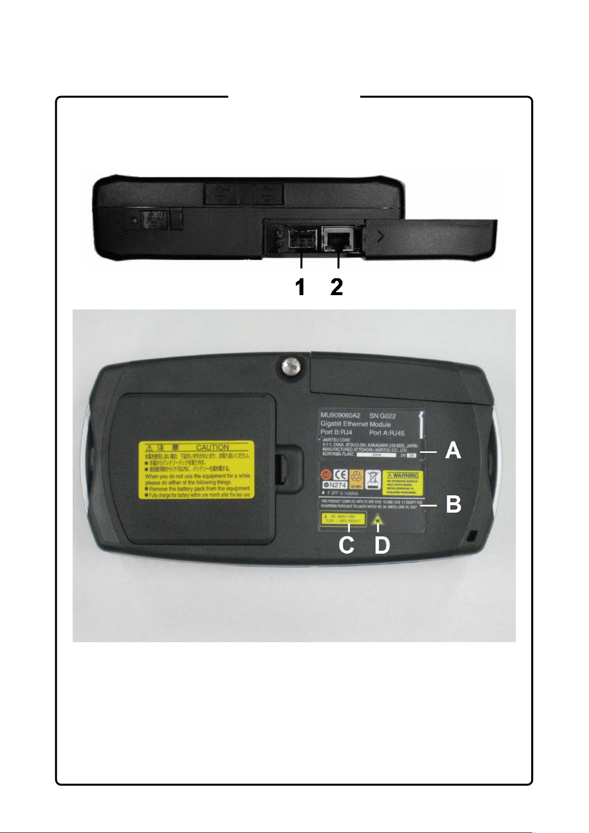
Table 3 Indication Labels on Product
Type Sample Affixed to: Model Name
1 Explanation
2 Certification
3 Identification Figure 1, A All
4 Warning
Figure 1, C All
Figure 1, B All
Figure 1, D All
viii
For Safety
Laser Radiation Markings
Figure 1 Locations of Laser Beam Apertures and Affixed Labels
ix
Ni-MH
For Safety
FOR EU & EFTA CUSTOMERS
Please Recycle.
Read the following when using products to which the mark shown on the
above is attached.
The product that you have purchased contains a rechargeable battery.
The battery is recyclable. At the end of its useful life, under various state
and local laws, it may be illegal to dispose of this battery into the
municipal waste. Check with your local solid-waste disposal officials for
details of recycling options or proper disposal in your area.
Before disposing of this product, discharge the battery and mail it to
your Anritsu Service or Sales office.
1. Disconnect the AC adapter, if used.
2. Turn the power switch to on.
3. Leave the product on until the power indicator goes off; the battery is
now discharged.
4. Remove the battery.
5. Insulate the battery terminals with adhesive tape.
6. Please recycle in accordance with your national or regional
legislation.
Nach gebrauch der Verkaufsstelle zurückgeben.
Après usage à rapporter au point de vente.
x

Use in a
E
U
Atmospheres
For Safety
CAUTION
External
Storage Media
Residential
nvironment
se in Corrosive
This equipment uses USB flash drives as external storage media for
storing data and programs.
If this media is mishandled or becomes faulty, important data may be lost.
It is recommended to periodically back up all important data and
programs to protect them from being lost accidentally.
Anritsu will not be held responsible for lost data.
Pay careful attention to the following points.
● Never remove the USB flash drive from the equipment while it is
being accessed.
● The USB flash drive may be damaged by static electric charges.
This equipment is designed for an industrial environment.
In a residential environment, this equipment may cause radio
interference in which case the user may be required to take adequate
measures.
Exposure to corrosive gases such as hydrogen sulfide, sulfurous acid,
and hydrogen chloride will cause faults and failures.
Note that some organic solvents release corrosive gases.
xi

Equipment Certificate
Anritsu Corporation certifies that this equipment was tested before shipment
using calibrated measuring instruments with direct traceability to public
testing organizations recognized by national research laboratories, including
the National Institute of Advanced Industrial Science and Technology, and
the National Institute of Information and Communications Technology, and
was found to meet the published specifications.
Anritsu Warranty
Anritsu Corporation will repair this equipment free-of-charge if a malfunction
occurs within one year after shipment due to a manufacturing fault.
However, software fixes will be made in accordance with the separate
Software End-User License Agreement. Moreover, Anritsu Corporation will
deem this warranty void when:
The fault is outside the scope of the warranty conditions separately
●
described in the operation manual.
The fault is due to mishandling, misuse, or unauthorized modification or
●
repair of the equipment by the customer.
The fault is due to severe usage clearly exceeding normal usage.
●
The fault is due to improper or insufficient maintenance by the customer.
●
The fault is due to natural disaster, including fire, wind, flooding,
●
earthquake, lightning strike, or volcanic ash, etc.
The fault is due to damage caused by acts of destruction, including civil
●
disturbance, riot, or war, etc.
The fault is due to explosion, accident, or breakdown of any other
●
machinery, facility, or plant, etc.
The fault is due to use of non-specified peripheral or applied equipment
●
or parts, or consumables, etc.
The fault is due to use of a non-specified power supply or in a
●
non-specified installation location.
The fault is due to use in unusual environments
●
The fault is due to activities or ingress of living organisms, such as
●
insects, spiders, fungus, pollen, or seeds.
In addition, this warranty is valid only for the original equipment purchaser. It
is not transferable if the equipment is resold.
Anritsu Corporation shall assume no liability for injury or financial loss of the
customer due to the use of or a failure to be able to use this equipment.
(Note)
.
xii

Note:
For the purpose of this Warranty, "unusual environments" means use:
In places of direct sunlight
●
In dusty places
●
In liquids, such as water, oil, or organic solvents, and medical fluids, or
●
places where these liquids may adhere
In salty air or in place chemically active gases (sulfur dioxide, hydrogen
●
sulfide, chlorine, ammonia, nitrogen oxide, or hydrogen chloride etc.) are
present
In places where high-intensity static electric charges or electromagnetic
●
fields are present
In places where abnormal power voltages (high or low) or instantaneous
●
power failures occur
In places where condensation occurs
●
In the presence of lubricating oil mists
●
In places at an altitude of more than 2,000 m
●
In the presence of frequent vibration or mechanical shock, such as in
●
cars, ships, or airplanes
Anritsu Corporation Contact
In the event that this equipment malfunctions, contact an Anritsu Service and
Sales office. Contact information can be found on the last page of the printed
version of this manual, and is available in a separate file on the PDF version.
xiii

This product and its manuals may require an Export License/Approval by
the Government of the product's country of origin for re-export from your
country.
Before re
contact us to confirm
whet
When you dispose of export-controlled items, the products/manuals need
to be broken/shredded so as not to be unlawfully used for military purpose.
Anritsu group promotes recycling activities in order to reuse available
resources and save energy. This product may use recycled parts
(mechanical components) that conform to Anritsu’s quality standards.
www.dtsc.ca.gov/hazardouswaste/perchlorate
Notes On Export Management
-exporting the product or manuals, please
her they are export-controlled items or not.
Reuse parts
FOR CALIFORNIA USA ONLY
This product contains a CR Coin Lithium Battery which contains
Perchlorate Material – special handling may apply; See
xiv

Crossed-out Wheeled Bin Symbol
Equipment marked with the Crossed-out Wheeled Bin Symbol complies with
council directive 2012/19/EU (the “WEEE Directive”) in European Union.
For Products placed on the EU market after August 13, 2005, please contact
your local Anritsu representative at the end of the product's useful life to
arrange disposal in accordance with your initial contract and the local law.
xv

Software End-User License Agreement (EULA)
Please carefully read and accept this Software End-User License Agreement (hereafter this EULA)
before using (includes executing, copying, installing, registering, etc.) this Software (includes programs,
databases, scenarios, etc., used to operate, set, etc., Anritsu electronic equipment, etc.). By using this
Software, you shall be deemed to have agreed to be bound by the terms of this EULA, and Anritsu
Corporation (hereafter Anritsu) hereby grants you the right to use this Software with the Anritsu
specified equipment (hereafter Equipment) for the purposes set out in this EULA.
Article 1. Grant of License and Limitations
1. You may not to sell, transfer, rent, lease,
lend, disclose, sublicense, or otherwise
distribute this Software to third parties,
whether or not paid therefor.
2. You may make one copy of this Software for
backup purposes only.
3. You are not permitted to reverse engineer,
disassemble, decompile, modify or create
derivative works of this Software.
4. This EULA allows you to install one copy of
this Software on one piece of Equipment.
Article 2. Disclaimers
To the extent not prohibited by law, in no
event shall Anritsu be liable for direct, or any
incidental, special, indirect or consequential
damages whatsoever, including, without
limitation, damages for loss of profits, loss of
data, business interruption or any other
commercial damages or losses, and damages
claimed by third parties, arising out of or
related to your use or inability to use this
Software, unless the damages are caused due
to Anritsu’s intentional or gross negligence.
Article 3. Limitation of Liability
1. If a fault (bug) is discovered in this Software,
failing this Software to operate as described
in the operation manual or specifications
even though you have used this Software as
described in the manual, Anritsu shall at its
own discretion, fix the bug, or replace the
software, or suggest a workaround,
free-of-charge, provided, however, that the
faults caused by the following items and any
of your lost or damaged data whatsoever
shall be excluded from repair and the
warranty.
i) If this Software is deemed to be used
for purposes not described in the
operation manual or specifications.
ii) If this Software has been used in
conjunction with other
non-Anritsu-approved software.
iii) If this Software or the Equipment has
been modified, repaired, or otherwise
altered without Anritsu's prior
approval.
iv) For any other reasons out of Anritsu's
direct control and responsibility, such
as but not limited to, natural disasters,
software virus infections, or any
devices other than this Equipment, etc.
2. Expenses incurred for transport, hotel, daily
allowance, etc., for on-site repairs or
replacement by Anritsu engineers
necessitated by the above faults shall be
borne by you.
3. The warranty period for faults listed in
Section 1 of this Article shall be either 6
months from the date of purchase of this
Software or 30 days after the date of repair
or replacement, whichever is longer.
xvi

Article 4. Export Restrictions
You shall not use or otherwise export or
re-export directly or indirectly this Software
except as authorized by the laws and
regulations of Japan and the United States,
etc. In particular, this Software shall not be
exported or re-exported (a) into any Japan or
US embargoed countries or (b) to anyone
restricted by the Japanese export control
regulations, or the US Treasury
Department's list of Specially Designated
Nationals or the US Department of
Commerce Denied Persons List or Entity
List. In using this Software, you warrant
that you are not located in any such
embargoed countries or on any such lists.
You also agree that you will not use or
otherwise export or re-export this Software
for any purposes prohibited by the Japanese
and US laws and regulations, including,
without limitation, the development, design
and manufacture or production of missiles or
nuclear, chemical or biological weapons of
mass destruction, and conventional
weapons.
Article 5. Change of Terms
Anritsu may change without your approval
the terms of this EULA if the changes are for
the benefit of general customers, or are
reasonable in light of the purpose of this
EULA and circumstances of the changes. At
the time of change, Anritsu will inform you
of those changes and its effective date, as a
general rule 45 days, in advance on its
website, or in writing or by e-mail.
Article 6. Termination
1. Anritsu may terminate this EULA
immediately if you violate any conditions
described herein. This EULA shall also be
terminated immediately by Anritsu if there
is any good reason that it is deemed difficult
to continue this EULA, such as your
violation of Anritsu copyrights, patents, etc.
or any laws and ordinances, or if it turns out
that you belong to an antisocial organization
or has a socially inappropriate relationship
with members of such organization.
2. You and Anritsu may terminate this EULA
by a written notice to the other party 30
days in advance.
Article 7. Damages
If Anritsu suffers any damages or loss,
financial or otherwise, due to your violation
of the terms of this EULA, Anritsu shall
have the right to seek proportional damages
from you.
Article 8. Responsibility after Termination
Upon termination of this EULA in
accordance with Article 6, you shall cease all
uses of this Software immediately and shall
as directed by Anritsu either destroy or
return this Software and any backup copies,
full or partial, to Anritsu.
Article 9. Negotiation for Dispute
Resolution
If matters of interpretational dispute or
items not covered under this EULA arise,
they shall be resolved by negotiations in
good faith between you and Anritsu.
Article 10. Governing Law and Court of
Jurisdiction
This EULA shall be governed by and
interpreted in accordance with the laws of
Japan without regard to the principles of the
conflict of laws thereof, and any disputes
arising from or in relation to this EULA that
cannot be resolved by negotiation described
in Article 9 shall be subject to and be settled
by the exclusive agreed jurisdiction of the
Tokyo District Court of Japan.
Revision History:
February 29th, 2020
xvii

The following actions are strictly prohibited for all of the software
Analyzing the incorporated software including but not limited to
modifying, decompiling, disassembling, and reverse engineering.
place.
Notice
installed in this product or otherwise provided by Anritsu:
1. Copying, except for archival purposes.
2. Transferring to a third party separately from this product.
3.
Cautions Against Computer Virus Infection
● Copying files and data
Only files that have been provided directly from Anritsu or generated
using Anritsu equipment should be copied to the instrument.
All other required files should be transferred by means of USB flash
drive or CompactFlash media after undergoing a thorough virus
check.
● Adding software
Do not download or install software that has not been specifically
recommended or licensed by Anritsu.
● Network connections
Ensure that the network has sufficient anti-virus security protection in
xviii

CE Conformity Marking
Anritsu affixes the CE conformity marking on the following product(s) in
accordance with the Directive 768/2008/EC to indicate that they conform to
the EMC, LVD, and RoHS directive of the European Union (EU).
CE marking
1. Product Model
Model: MT9090A Mainframe
MU909060A1 Gigabit Ethernet Module RJ45 SFP
MU909060A2 Gigabit Ethernet Module RJ45 RJ45
MU909060A3 Gigabit Ethernet Module SFP SFP
2. Applied Directive
EMC: Directive 2014/30/EU
LVD: Directive 2014/35/EU
RoHS: Directive 2011/65/EU, (EU) 2015/863
3. Applied Standards
EMC: Emission: EN 61326-1: 2013 (Class A)
●
Immunity: EN 61326-1: 2013 (Table 2)
IEC 61000-4-2 (ESD) B
IEC 61000-4-3 (EMF) A
IEC 61000-4-4 (Burst) B
IEC 61000-4-5 (Surge) B
IEC 61000-4-6 (CRF) A
IEC 61000-4-11 (V dip/short) B, C
Performance Criteria*
*: Performance Criteria
A: The equipment shall continue to operate as intended during and
after the test. No degradation of performance or loss of function
is allowed below a performance level specified by the
manufacturer, when the equipment is used as intended. The
performance level may be replaced by a permissible loss of
performance. If the minimum performance level or the
permissible performance loss is not specified by the
manufacturer, either of these may be derived from the product
xix

Ser
If the third digit of the serial number is "7", the product
complies with Directive 2011/65/EU as amended by (EU)
2015/863.
(Pb,Cd,Cr6+,Hg,PBB,PBDE,DEHP,BBP,DBP,DIBP)
If the third digit of the serial number is "6", the product
complies with Directive 2011/65/EU.
(Pb,Cd,Cr6+,Hg,PBB,PBDE)
Third digit
description and documentation and what the user may
reasonably expect from the equipment if used as intended.
B: The equipment shall continue to operate as intended after the
test. No degradation of performance or loss of function is
allowed below a performance level specified by the
manufacturer, when the equipment is used as intended. The
performance level may be replaced by a permissible loss of
performance. During the test, degradation of performance is
however allowed. No change of actual operating state or stored
data is allowed. If the minimum performance level or the
permissible performance loss is not specified by the
manufacturer, either of these may be derived from the product
description and documentation and what the user may
reasonably expect from the equipment if used as intended.
C: Temporary loss of function is allowed, provided the function is
self-recoverable or can be restored by the operation of the
controls.
Harmonic current emissions:
EN 61000-3-2: 2014 (Class A equipment)
: No limits apply for this equipment with an active input
power under 75 W.
LVD: EN 61010-1: 2010 (Pollution Degree 2)
•
RoHS: EN IEC 63000: 2018 (Category 9)
•
xx
ial number example

4. Contact
Name: Anritsu GmbH
Address, city: Nemetschek Haus, Konrad-Zuse-Platz 1
81829 München,
Country: Germany
Name: ANRITSU EMEA Ltd.
Address, city: 200 Capability Green, Luton
Bedfordshire, LU1 3LU
Country: United Kingdom
xxi

RCM Conformity Marking
Anritsu affixes the RCM mark on the following product(s) in accordance with
the regulation to indicate that they conform to the EMC framework of
Australia/New Zealand.
RCM marking
1. Product Model
Model: MT9090A Mainframe
MU909060A2 Gigabit Ethernet Module RJ45 RJ45
MU909060A3 Gigabit Ethernet Module SFP SFP
2. Applied Standards
EMC: Emission: EN 61326-1: 2013 (Class A equipment)
MU909060A1 Gigabit Ethernet Module RJ45 SFP
xxii

About This Manual
The purpose of this operation manual is to explain how to set up the
MU909060A Series Gigabit Ethernet Module and how to use the various
features and modes. This manual is designed to appeal to professionals
with the technical background to use this type of instrument.
Descriptions in this manual assume a knowledge of Ethernet and IP
technology.
I

Table of Contents
For Safety .................................................... iii
About This Manual........................................ I
Chapter 1 Overview .................................... 1-1
1.1 Configuration ................................................................. 1-2
1.2 Front Panel ................................................................... 1-6
1.3 Back Panel .................................................................... 1-10
1.4 Bottom Panel ................................................................ 1-15
1.5 Top Connector Panel .................................................... 1-16
1.6 Changing Test Module .................................................. 1-29
1.7 Basic Usage Notes ....................................................... 1-31
Chapter 2 General Operation .................... 2-1
2.1 Power Up/Power Down ................................................. 2-3
2.2 General Functions ......................................................... 2-5
2.3 Mass Storage ................................................................ 2-13
2.4 Print Screen .................................................................. 2-20
2.5 Status Screen ............................................................... 2-21
2.6 Result Screens .............................................................. 2-27
2.7 Save and Load .............................................................. 2-33
2.8 Setup ............................................................................. 2-40
2.9 Test Reports ................................................................. 2-42
Chapter 3 Ethernet Application ................. 3-1
3.1 Application Ethernet Status .......................................... 3-3
3.2 Application Ethernet Setup ........................................... 3-4
3.3 Generator Test .............................................................. 3-35
3.4 BER Test ....................................................................... 3-63
3.5 Stimuli ........................................................................... 3-66
3.6 Ping Test ....................................................................... 3-70
3.7 Cable Test ..................................................................... 3-75
3.8 RFC2544 Tests ............................................................. 3-78
3.9 HTTP/FTP Download Test ............................................ 3-100
3.10 Trace Route Test .......................................................... 3-107
3.11 Y.1564 Suite ................................................................. 3-111
3.12 Address Wizard ............................................................. 3-205
II

1
3.13 OAM Loopback Application .......................................... 3-215
Chapter 4 Application Reflector ................ 4-1
4.1 Status ............................................................................ 4-2
4.2 Setup Interface .............................................................. 4-3
4.3 Result ............................................................................ 4-7
Chapter 5 Pass Through ............................ 5-1
5.1 Status ............................................................................ 5-2
5.2 Setup Interface .............................................................. 5-3
5.3 Testing .......................................................................... 5-5
5.4 Result ............................................................................ 5-6
Chapter 6 Updating Firmware ................... 6-1
6.1 Updating Firmware ........................................................ 6-2
Chapter 7 Service Information .................. 7-1
7.1 Self Diagnostics ............................................................ 7-2
7.2 Maintenance ................................................................. 7-6
7.3 Disposal ........................................................................ 7-7
2
3
4
5
6
7
Appendix Index
Appendix A Specifications ......................... A-1
Appendix B Remote Control ....................... B-1
Appendix C PC Application Manual ........... C-1
Appendix D Software Licenses .................. D-1
Index .......................................................... Index-1
III

IV.

Chapter 1 Overview
1-1
Overview
It is important to know the layout, use, and functions of the front panel,
back panel, and top connector panel of the Network Master.
1.1
Configuration................................................................. 1-2
1.1.1 Standard Configuration..................................... 1-2
1.1.2 Option ............................................................... 1-3
1.2 Front Panel ................................................................... 1-6
1.2.1 LCD................................................................... 1-7
1.2.2 Panel Keys ....................................................... 1-8
1.3 Back Panel .................................................................. 1-10
1.3.1 Power and Batteries ....................................... 1-11
B1.3.2 Installing Ni-MH Battery Pack ......................... 1-12
1.3.3 Battery Replacement – Ni-MH Pack To
AA Ni-MH ........................................................ 1-14
1.4 Bottom Panel .............................................................. 1-15
1.5 Top Connector Panel .................................................. 1-16
1.5.1 AC Charger/Adapter ....................................... 1-17
1.5.2 Battery Status LED ......................................... 1-20
1.5.3 RJ45 Port ........................................................ 1-21
1.5.4 SFP Port ......................................................... 1-22
1.5.5 Connecting Peripheral Devices ...................... 1-24
1.5.6 Cautions on Handling Optical Fiber Cables ... 1-27
1.6 Changing Test Module ................................................ 1-29
1.7 Basic Usage Notes ..................................................... 1-31
1

Chapter 1 Overview
1-2
Body
MT9090A
Mainframe
1
Module
MU909060A1
Gigabit Ethernet Module
1*
One RJ-45, One
SFP
MU909060A2
Gigabit Ethernet Module
1*
Two RJ-45
MU909060A3
Gigabit Ethernet Module
1*
Two SFP
Accessary
W3173AE
Gigabit Ethernet Module
Quick guide
1 Z1234A
Network Master Gigabit
Ethernet Tester CD
1
G0203A
AC charger/adapter
1 G0202A
Ni-MH battery pack
1
B0601B
Standard Soft Case
1 Z1023A
Strap
1
1.1 Configuration
1.1.1 Standard Configuration
The table below lists the standard configuration of the Network Master
series Gigabit Ethernet Module.
If you find any missing or broken components, immediately contact
Anritsu or our sales dealer.
Table 1.1.1-1 Standard configuration
Item
Model or
order No.
*: Exclusive
Name Qty. Remarks

1.1 Configuration
1-3
Overview
1.1.2 Option
MU909060A1-001
RFC2544 test
Software Option
MU909060A1-002
Multistream
Software Option
MU909060A1-003
Stacked VLAN
Software Option
MU909060A1-004
MPLS
Software Option
MU909060A1-005
Remote GUI
Software Option
MU909060A1-006
Channel Stats
Software Option
MU909060A1-007
Y.1564 Suite
Software Option
MU909060A2-001
RFC2544 test
Software Option
MU909060A2-002
Multistream
Software Option
MU909060A2-003
Stacked VLAN
Software Option
MU909060A2-004
MPLS
Software Option
MU909060A2-005
Remote GUI
Software Option
MU909060A2-006
Channel Stats
Software Option
MU909060A2-007
Y.1564 Suite
Software Option
MU909060A3-001
RFC2544 test
Software Option
MU909060A3-002
Multistream
Software Option
MU909060A3-003
Stacked VLAN
Software Option
MU909060A3-004
MPLS
Software Option
MU909060A3-005
Remote GUI
Software Option
MU909060A3-006
Channel Stats
Software Option
MU909060A3-007
Y.1564 Suite
Software Option
Below Options are available for Gigabit Ethernet Module.
Table 1.1.2-1 Option
Model Name Remark
1
RFC2544 test
This option enables RFC 2544 testing described in Section 3.8 “RFC2544
Tests”.
Multistream
This option generates Multistream described in Section 3.3 “Generator
Tes t” .
Stacked VLAN
This option enables the VLAN stacking functions, described in Section 3.3
“Generator Test”.
MPLS
This option enables the MPLS stacking functions, described in Section 3.3
“Generator Test”.
Remote GUI
This option enables the Remote Control feature, described in Section 3.3
“Generator Test”.
Chapter 1 Overview
1-4
Top Menu
Up/Down/Left/Right
Self
Diagnostics
Set
Menu
Up/Down
Set
Channel Stats
This option enables the Channel Statistics feature, described in Section
3.3 “Generator Test”.
Y.1564 Suite
This option enables the Y.1564 Suite feature, described in Section 3.11
“Y.1564 Suite”.
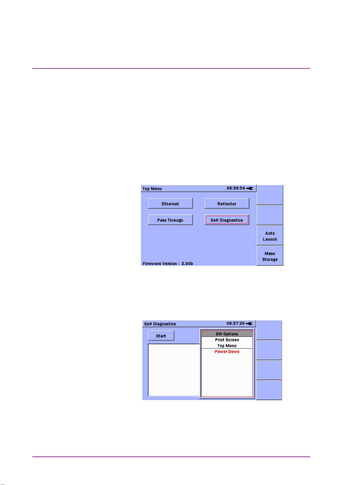
To check the installed options on a unit, power-on the unit and wait for
the
display, as shown in Figure 1.1.2-1 below. Use the
-arrow keys to move the highlight over the
application button.
Figure 1.1.2-1 Top Menu
Press the
shown in Figure 1.1.2-2 below.
Use the
item. Press the
displayed as shown in Figure 1.1.2-3 below.
key. The Self Diagnostics application will start. Press the
key. The context menu for the application will be displayed as
Figure 1.1.2-2 Context Menu
-arrow keys to move the highlight over the SW options
key to complete the selection. The SW Options will be

1.1 Configuration
1-5
Overview
Set
Menu
Down
Top Menu
Set
Top Menu
Figure 1.1.2-3 SW Options Window
1
Review the SW Options and press the
finished.
Press the
over the
return to the
key. Use the Up/
item. Press the
.
key to release the window when
-arrow keys to move the highlight
key to complete the selection and

Chapter 1 Overview
1-6
1.2 Front Panel
The front panel contains the operation controls and LCD display.
Figure 1.2-1 Front Panel Layout
LCD
Soft keys
Start key
Arrow keys and Set key
Menu/Power key

1.2 Front Panel
1-7
Overview
1.2.1 LCD
Displays title of current screen
Displays current time in 24-hour format
(hh:mm:ss)
Shows unit connected to external power
illustrating remaining charge
Changes with screen display
Display on-screen details
The graphical user interface varies with the selected mode but each
screen shares common elements as shown in the figure below.
1
Screen title
Time display
Battery or plug
icon
Presentation field
Soft keys
supply (plug icon) or operating on battery
power (battery icon) with graphic

Chapter 1 Overview
1-8
The unit has four soft keys (F1 thru F4) on the
Press to start or stop the test.
statistics counters.
1.2.2 Panel Keys
Soft keys
right hand side of the LCD. The function of each
key is determined by the current operation mode
and is displayed on the screen to the left of the key.
Start key
Note:
When Running a Generator test under certain
conditions, this key may be used to re-set the

1.2 Front Panel
1-9
Overview
Arrow keys and Set key
The arrow keys (Left/Right/Up/Down) have the
Left arrow key
Moves cursor/highlight to left
Right arrow key
Moves cursor/highlight to right
Up arrow key
Moves cursor/highlight up
Down arrow key
Moves cursor/highlight down
Set key
Selects highlighted item
When unit is off:
•
Press the Menu/Power key to power up.
When unit is on:
•
Press the Menu/Power key to display the
1
Menu/Power key
following functions:
pop-up menu.
Power Down can be selected from the
pop-up menu.

Chapter 1 Overview
1.3 Back Panel
The back panel contains the battery compartment and a fastener to
secure the test module to the Network Master main unit. There are also
various compliance and warning labels as well as the model/serial
number (item 3 in Figure 1.3-1).
Figure 1.3-1 Back Panel
Battery compartment
Fastener
Module model/serial label
Compliance and warning labels
1-10

1.3 Back Panel
1-11
Overview
1.3.1 Power and Batteries
•
External AC charger/adapter:
•
External car plug cord/adapter (optional):
•
Ni-MH rechargeable battery pack:
•
Replaceable batteries:
The unit can be powered in three ways.
Use this adapter to provide power from an AC source or to charge the
Ni-MH (nickel-metal hydride) battery pack. For details see “1.5.1
AC Charger/Adapter”.
Use this adapter to provide power from a car to charge the Ni-MH
battery pack.
When installed, this battery powers the unit.
Note:
Only use the Anritsu Ni-MH battery pack. Anritsu does not
guarantee the safety and function of other battery packs.
1
If no AC charger/adapter or Ni-MH battery is available, the unit can
be powered by four AA Ni-MH batteries.

Chapter 1 Overview
1-12
B
1.3.2 Installing Ni-MH Battery Pack
Install the Ni-MH battery pack as described below.
1. Power down the unit.
2. Open the battery compartment (Figure 1.3.2-1) by pulling the latch
while lifting the battery compartment cover.
3. Remove any installed batteries.
4. Plug the connector on the Ni-MH battery pack into the socket next to
the module release latch (white plastic latch in battery
compartment).
5. Slide the Ni-MH battery pack into the battery compartment making
sure that the battery release pull (red ribbon) is tucked underneath
the pack, but leaving enough of the release pull exposed to remove
the battery pack later when necessary. Also ensure the THIS SIDE
UP label is visible.
6. Close the battery compartment cover.
Figure 1.3.2-1 Open Battery Compartment
Ni-MH battery pack plug
Module release latch
Ni-MH battery pack
Battery release pull (red ribbon)

1.3 Back Panel
1-13
Overview
WARNING
ALWAYS power down the Network Master before removing
the Ni-MH battery pack.
The battery pack and/or Network Master may be damaged if the
power is on while the pack is removed.
WARNING
Before storing the Network Master for a long time (1 to 2
months), remove the Ni-MH battery pack to avoid damage
to the battery pack and/or Network Master.
If storing the Network Master with the Ni-MH battery pack
installed, always recharge the battery pack periodically (every 1
to 2 months).
1

Chapter 1 Overview
1-14
1.3.3 Battery Replacement – Ni-MH Pack To AA Ni-MH
Replace the Ni-MH battery pack with AA Ni-MH batteries as described
below:
1. Power down the unit. Open the battery compartment (Figure 1.3.2-1
for location) by pulling the latch while lifting the battery
compartment cover.
2. Using the battery release pull (red ribbon), lift out the Ni-MH
Battery Pack and unplug it from its socket next to the module release
latch (white plastic latch).
3. Insert four new AA Ni-MH batteries in the compartment according to
the battery polarity symbols (+ and –) next to the battery contacts.
4. Close the battery compartment cover.
WARNING
ALWAYS power down the unit before removing old AA
Ni-MH batteries.
If the batteries are removed while the power is on, settings and
data files may be lost.
WARNING
Remove AA Ni-MH batteries from the Network Master when
storing it for a long period of time (1 to 2 months).
Storing the Network Master for a long period of time with AA
Ni-MH batteries installed will decrease the discharge capacity
of the batteries.

1.4 Bottom Panel
1-15
Overview
1.4 Bottom Panel
The bottom panel has a label with the main unit model/serial number.
1
Figure 1.4-1 Bottom Panel

Chapter 1 Overview
1-16
MU909060A1
RJ45
SFP
MU909060A2
RJ45
RJ45
MU909060A3
SFP
SFP
1.5 Top Connector Panel
The top connector panel contains the measurement ports used to connect
optical fibers or RJ45 cables to the network under test plus USB ports for
uploading and downloading files. The 9 V DC Power Connector and
Battery Status LED are also on the top panel.
Figure 1.5-1 shows a typical top panel.
Note:
The top panel configuration differs with the installed optics and
options.
Figure 1.5-1 MU909060A1 Top Panel with
Open Measurement Ports Cover
Measurement Port A
Measurement Port B
9 V DC Power Connector
Battery Status LED
USB (Type A) port
USB (Type B) port
Table 1.5-1 Models Names and Measurement Ports
Model Name Measurement Port A Measurement Port B

1.5 Top Connector Panel
1-17
Overview
1.5.1 AC Charger/Adapter
The unit includes an AC Charger/Adapter. The Ni-MH Battery Pack
requires 3 hours to charge fully. The Network Master will not recharge
the Ni-MH Battery Pack while it is operating.
The AC Charger/Adapter has four interchangeable plugs. Use the correct
plug.
1
Figure 1.5.1-1 AC Charger/Adapter with Guard
Guard
Release

Chapter 1 Overview
1-18
To prepare the AC Charger/Adapter:
1. Pull the Release and remove the Guard if it is in place (Figure
1.5.1-1).
2. Select the required plug from the AC Charger/Adapter kit. See the
following figure.
3. Hold the Release down and insert the plug adapter, making sure that
the tab on the plug adapter is seated in the slot on the top of the AC
Charger/Adapter.
4. Release the Release, making sure that the tab on the Release is
seated in the slot on the base of the plug adapter.
AC Power Operation
Operate the Network Master on AC power as described below.

1.5 Top Connector Panel
1-19
Overview
Menu/Power
To use the AC Charger/Adapter:
1. Open the cover on the Network Master 9 V DC Connector on the top
connector panel (Figure 1.5-1) and plug in the jack from the AC
Charger/Adapter.
2. Plug the AC Charger/Adapter into an AC outlet.
Note:
Ensure that the AC Charger/Adapter has the correct plug.
1
3. Press the
key to start the Network Master.
CAUTION
Use the Network Master only with the Anritsu AC
Charger/Adapter.
Anritsu does not guarantee the safety and functionality of other
AC charger/adapters.
To charge the Ni-MH Battery Pack:
1. Power down the unit.
2. Open the cover on the Network Master 9 V DC Connector on the top
connector panel (Figure 1.5-1) and plug in the jack from the AC
Charger/Adapter.
3. Plug the AC Charger/Adapter into an AC outlet.
Note:
Ensure that the AC Charger/Adapter has the correct plug.
4. When the battery pack is fully charged, the Battery Status LED is lit
green. See “Battery Status LED” for details. A full charge takes about
3 hours.
Note:
The Network Master will not charge the battery pack while it is
being operated.

Chapter 1 Overview
1-20
1.5.2 Battery Status LED
The Battery Status LED displays the current status of the
Ni-MH Battery Pack:
Red:
The battery pack is not charging for one of the following reasons:
When starting to charge, the temperature of the battery pack is lower
•
than 5°C or higher than 45°C. In this situation, disconnect the AC
adapter from the Network Master and wait until the temperature of
the battery pack is within the 5° to 45°C range.
While charging, the temperature of the battery pack becomes lower
•
than 5°C or higher than 60°C. In this situation, charging resumes
automatically as soon as the temperature of the battery pack is within
the 5° to 45°C range.
Charging has not finished within about 3 hours it normally takes to
•
charge the battery pack fully. To avoid overcharging, the unit stops
charging after about 3 hours.
If the Battery Status LED is always red, there is a problem with the
battery pack. Please contact the Anritsu Technical Support Center or your
local Anritsu representative (see Anritsu Corporation Contact).
Orange
The AC Charger/Adapter is plugged in and the battery pack is
•
charging.
Green
The AC Charger/Adapter is plugged in and the battery pack is fully
•
charged or the Network Master is operating. The battery pack will
continue charging in maintenance charge mode.
Note:
Charging or discharging can be started at any time with minimum
battery memory issues. The battery pack can be left in maintenance
charge indefinitely.

1.5 Top Connector Panel
1-21
Overview
1.5.3 RJ45 Port
The RJ45 port (item 1 in Figure 1.5-1) offers access to the optional RJ45
test port. This port has an RJ45 connector that accepts standard RJ45
cables.
Note:
See Table 1.5-1
Connecting Cable to RJ45 port
1. Open the cover on the port (Figure 1.5-1).
2. Plug the RJ45 cable into the port
X
for details on which models have the RJ45 option.
1

Chapter 1 Overview
1-22
1.5.4 SFP Port
The SFP ports (item 2 in Figure 1.5-1) are located on the top panel of the
Network Master and are accessed by opening the sliding cover (Figure
1.5-1). The modules can be either optical or electrical. The optical modules
have LC connectors and the electrical modules have an RJ45 connector.
Cleaning Optical Connectors
Cleaning the optical connectors as described below.
1. Open the port cover.
2. Blow clean, dry compressed air on the tip of the ferrule.
3. Wipe the ferrule tip clean with a precision cleaning tissue or a lint
free (foam) swab moistened with isopropyl alcohol.
4. Dry the ferrule tip with clean, dry compressed air.
Dirty Ferrule Tip Clean Ferrule Tip
Figure 1.5.4-1 Magnified Ferrule Tip
5. Option: With the Network Master powered down, inspect the ferrule
using a hand-held microscope or magnifier. It should look like the
clean ferrule tip in Figure 1.5.4-1.

1.5 Top Connector Panel
1-23
Overview
Connecting Fiber to Optical SFP modules
The optical SFP modules are used to connect optical fiber for optical test
applications.
To connect a fiber to the SFP module:
1. Open the cover on the port (Figure 1.5-1).
2. Connect the test fiber to the measurement port.
WARNING
Never force the connector ferrule or insert it at an angle
into the adapter.
Optical fibers suffer loss caused by microbends or other stress.
Position the patch cord to minimize mechanical strain.
1

Chapter 1 Overview
1-24
Set
1.5.5 Connecting Peripheral Devices
The unit has two USB ports for connecting a USB device or PC.
USB (Type A) port
The USB (Type A) port is used to connect a USB flash drive (version 1.1)
to the unit. Some USB flash drives are not supported by this port.
Figure 1.5.5-1 USB (Type A) Port
The following message is displayed when the unit detects that a USB
device has been connected.
Figure 1.5.5-2 USB Storage Device Detected Dialog
Press the
storage.
key to close the dialog and set the USB device as the default

1.5 Top Connector Panel
1-25
Overview
Set
When the USB device is removed the following message is displayed
(Figure 1.5.5-2).
Figure 1.5.5-3 USB Storage Device Removed Dialog
1
Press the
default storage drive.
key to close the dialog so the internal drive is set as the
WARNING
Do not remove USB flash drive while it is being accessed
or the USB flash drive or data may be damaged.

Chapter 1 Overview
1-26
USB (Type B) port
The internal memory of the Network Master can be accessed directly from
a PC by connecting a PC to the USB (Type B) using a USB A to USB B
cable.
Figure 1.5.5-4 USB (Type B) Port
WARNING
Before disconnecting the USB cable between the Network
Master and PC always press Safely Remove Hardware in
the Notification area in Microsoft Windows
internal memory on the Network Master may be damaged.
, otherwise the
®

1.5 Top Connector Panel
1-27
Overview
1.5.6 Cautions on Handling Optical Fiber Cables
Optical fiber cables may degrade in performance or be damaged if
handled improperly.
Note the following points when handling them.
CAUTION
Do not pull the cable when removing the
connector.
Doing so may break the optical fiber inside the cable, or
remove the cable sheath from the optical connector.
1
CAUTION
Do not excessively bend, fold, or pinch an optical
fiber cable.
Doing so may break the optical fiber inside the cable.
Keep the bend radius of an optical fiber cable at 30 mm or
more. If the radius is less, optical fiber cable loss will
increase.

Chapter 1 Overview
1-28
CAUTION
Do not excessively pull on or twist an optical
fiber cable.
Also, do not hang anything by using a cable. Doing so may
break the optical fiber inside the cable.
CAUTION
Be careful not to hit the end of an optical
connector against anything hard such as the floor
or a desk by dropping the optical fiber cable.
Doing so may damage the connector end and increase
connection loss.
WARNING
Do not touch the end of a broken optical fiber
cable.
The broken optical fiber may pierce the skin, causing
injury.
CAUTION
Do not disassemble optical connectors.
Doing so may cause part to break or the performance to
degrade.

1.6 Changing Test Module
1-29
Overview
1.6 Changing Test Module
Remove the installed test module from the Network Master and install
the new test module as described below.
To change the test module:
1. Power down the unit.
2. Disconnect the AC Charger/Adapter, if connected.
3. Loosen the Captive Fastener on the back panel (item 2 in Figure
1.3-1). When loose, the fastener slips free but remains attached to the
test module.
4. Open the battery compartment (Figure 1.3-1) and remove the battery
pack or AA Ni-MH batteries.
5. Hold down the module release latch (white plastic latch in battery
compartment – item 2 in Figure 1.3.2-1) while pulling on the
Network Master to separate it from the test module.
1
Release the module Release latch after the Network Master and test
module have been separated.
WARNING
The Network Master and test module are a close fit. Be
careful when separating the two.
6. To install the new test module, align the two tabs on the back of the
Network Master (end opposite 100-pin connector) with the two slots
on the new test module (Figure 1.6-1).

Chapter 1 Overview
1-30
Figure 1.6-1 Alignment Tabs and Slots
Alignment tabs on Network Master main unit
Alignment slots on module
7. Applying firm but gentle pressure, place the Network Master main
unit on the test module. DO NOT force the two sections together.
8. Tighten the Captive Fastener.
9. Replace any removed battery pack or AA Ni-MH batteries.
10. Replace the battery compartment cover.

1.7 Basic Usage Notes
1-31
Overview
1.7 Basic Usage Notes
Measurement port cover
The cover prevents dust and other contaminants collecting in
the measurement port. Keep this cover closed except when a
cable is connected.
Condensation
Condensation may occur in the Network Master when it is taken
into a warm room after use outdoors, etc. In this case, allow the
Network Master to dry out thoroughly before powering up.
Temperature range
Use the unit within the operating temperature range (0° to
+40°C) and store it within the storage temperature range (–20°
to +60°C). If the unit is left in a car or other enclosed space for a
long time during summer, the ambient temperature may exceed
the specified range, resulting in malfunction.
1
WARNING
Safety
Only use the Anritsu AC Charger/Adapter or Ni-MH Battery
Pack, otherwise the unit may be damaged.
Laser
NEVER look directly into the Network Master optical connector
or end of a connected cable, otherwise laser light may enter the
eye and cause injury. In addition, some SFP modules output
high-power optical signals. To prevent damage to connected
equipment, check that any connected photo-receiver will not be
saturated. Anritsu accepts no responsibility for damage caused
to connected communications devices.
Maintenance
Anritsu recommends annual inspections (charged) of the
Network Master by an Anritsu Customer Service Center.
For other usage notes, read the safety-related information in this manual
thoroughly before use.

Chapter 1 Overview
1-32.

Chapter 2 General Operation
2-1
General Operation
This chapter describes the general system operation and setup.
Power Up/Power Down ................................................. 2-3
2.1
2.1.1 Power Up .......................................................... 2-3
2.1.2 Power Down ..................................................... 2-3
2.1.3 Temperature Monitoring ................................... 2-4
2.2 General Functions ........................................................ 2-5
2.2.1 Top Menu ......................................................... 2-5
2.2.2 Auto Launch Pop-up ......................................... 2-5
2.2.3 Mass Storage Menu ......................................... 2-5
2.2.4 Launching Applications .................................... 2-5
2.2.5 General Functions Pop-Up Menu ..................... 2-6
2.2.6 Setup ................................................................ 2-8
2.2.7 Help Function ................................................. 2-10
2.2.8 About Function ............................................... 2-11
2.2.9 Set to Defaults ................................................ 2-11
2.3 Mass Storage .............................................................. 2-13
2.3.1 Creating New Folder....................................... 2-14
2.3.2 Deleting File .................................................... 2-15
2.3.3 Deleting Multiple Files .................................... 2-16
2.3.4 Copying File .................................................... 2-17
2.3.5 Copying Multiple Files .................................... 2-18
2.3.6 Renaming File or Folder ................................. 2-19
2.4 Print Screen ................................................................ 2-20
2.5 Status Screen ............................................................. 2-21
2.5.1 Basic ............................................................... 2-22
2.5.2 ETH................................................................. 2-23
2.5.3 IP .................................................................... 2-24
2.5.4 SFP ................................................................. 2-25
2.5.5 Top Bar ........................................................... 2-25
2.6 Result Screens............................................................ 2-27
2.6.1 Result overview .............................................. 2-27
2.6.2 Summary ........................................................ 2-29
2.6.3 Event Log ....................................................... 2-30
2.6.4 Statistics ......................................................... 2-31
2.7 Save and Load ............................................................ 2-33
2.7.1 Save Setup ..................................................... 2-33
2.7.2 Load Setup ..................................................... 2-34
2.7.3 Save Results .................................................. 2-36
2.7.4 Load Results ................................................... 2-39
2.8 Setup ........................................................................... 2-40
2.8.1 Intelligent Setup .............................................. 2-40
2

Chapter 2 General Operation
2-2
2.9 Test Reports ............................................................... 2-42
2.9.1 Setup .............................................................. 2-43
2.9.2 Generating a report ........................................ 2-46

2.1 Power Up/Power Down
2-3
General Operation
2.1 Power Up/Power Down
Menu/Power
Menu/Power
Down
Power Down
Set
Yes
Set
Menu/Power
2.1.1 Power Up
Press the
during which the Anritsu splash screen is displayed before changing to
the Top Menu screen.
key. The Network Master performs a brief self-test
2
2.1.2 Power Down
Figure 2.1.1-1 Top Menu Screen
CAUTION
If a screen similar to the one shown above is not displayed
after power up, the Network Master may have failed the
self-test. Switch the unit off and on (power down/power up)
again. If the problem persists, contact the Anritsu
Technical Support Center or your local Anritsu
representative.
1. Press the
2. Use the
3. Press the
following message appears: “Are you sure you want to Power Down?”
arrow key to highlight
key to accept the highlighted menu selection. The
key to display a pop-up menu.
in the menu.
4. Highlight
Forcibly Power Down at any time by pressing the
for 10 s.
and press the
key.
key

Chapter 2 General Operation
2-4
2.1.3 Temperature Monitoring
The temperatures of the instrument and any connected SFP modules are
monitored.
Note:
The temperature of the SFP module is only monitored if the module
complies with the SFP Transceiver MultiSource Agreement and
has integrated digital diagnostic monitoring functions.
If the temperature of the instrument or one of the SFP modules reaches
its maximum specified value, the instrument will automatically power
down. Before this happens a pop-up temperature alarm dialog is
displayed to notify that a power down is imminent (Figure 2.1.3-1).
Figure 2.1.3-1 Temperature Alarm Pop-up Dialog
The pop-up dialog indicates whether the instrument or one of the SFP
modules has reached the maximum temperature.
Note:
There is a 4-second delay from displaying the pop-up dialog until
power down is started.

2.2 General Functions
2-5
General Operation
2.2 General Functions
F3
F4
Menu/Power
Auto Launch (F3)
Mass Storage (F4)
Left/Right/Up/Down
Set
2.2.1 Top Menu
The Top Menu provides access to:
The Ethernet application
•
The Reflector application
•
The Self Diagnostics application
•
The Pass Through application
•
The Auto Launch pop-up by pressing the
•
The Mass Storage menu by pressing the
•
The General Functions pop-up menu by pressing the
•
2.2.2 Auto Launch Pop-up
At the Top Menu, press
displayed. From this screen the Auto Launch feature can be enabled and
an application can be selected that will launch automatically upon
power-up.
key
key
. The Auto Launch screen is
2
key
2.2.3 Mass Storage Menu
At the Top Menu, press
displayed in the File Operations mode, to copy, delete, or rename files, as
well as to create new folders.
. The Mass Storage screen is
2.2.4 Launching Applications
1. At the Top Menu, use the
highlight the application to launch and press the
2. The Top Menu screen closes and the selected application is launched.
arrow keys to
key.

Chapter 2 General Operation
2-6
Menu/Power
Test Report
Save Setup
Save Results
Setup
Load
Help
2.2.5 General Functions Pop-Up Menu
Press the
menu.
This menu provides access to the following:
Figure 2.2.5-1 General Functions Pop-up Menu
key to display the General Functions pop-up
Some items will not be displayed according to the usage conditions.
Accesses general setup for the Network Master
Generates a report file of the results that are currently in
memory. Available on the Result overview and on the
specific result screens. CSV and PDF formats are
available.
Opens Mass Storage screen in Save mode to save setup
file
Only visible when test not running and not from Top
Menu
Refer to 2.7.1 “Save Setup” for further details.
Opens Mass Storage screen in Save mode to save results
file
Only visible when test not running and not from Top
Menu
Refer to 2.7.3 “Save Results” for further details.
Only visible from Top Menu
Opens Mass Storage screen in Load mode to load setup or
result file
Only visible when test not running and not from Top
Menu
Refer to 2.7.2 “Load Setup” and 2.7.4 “Load Results” for
further details.
Displays help for current screen

2.2 General Functions
2-7
General Operation
Mass Storage
Print Screen
Top Menu
Power Down
Closes currently running application and opens Top Menu
Opens Mass Storage screen in File Operations mode, to
copy, delete, or rename files, as well as to create new
folders
Captures current screen as an image file (in the currently
selected image format) to internal memory
2
screen
Starts power down

Chapter 2 General Operation
2-8
Menu/Power
Setup
Set
2.2.6 Setup
Use the following procedure to access the Setup screen
1. With the Network Master powered up, press the
the Top Menu. The General Functions pop-up menu is displayed with
highlighted.
2. Press the
key. The Basic Tab of the Setup screen is displayed.
Figure 2.2.6-1 Setup screen, Basic Tab
key at
Figure 2.2.6-2 Setup screen, Advanced Tab

2.2 General Functions
2-9
General Operation
Up
Down
Date & Time
Set
Left
Right
Up
Down
OK (F1)
Color Theme
Left
Right
Language
Left
Right
Auto Backlight
Left
Right
Auto Power Off
Left
Right
Apply
Set
Up, Down, Left
Right
Advanced
Screen Capture Format
Left
Right
Apply
Set
3. Use the
(a) Press the
(b) Use the
(c) Repeat steps 3(a) and 3(b) until the required date and time are
(d) Press
4. Highlight
scroll to the required color theme.
5. Highlight
to the required language.
6. Highlight
scroll to the required time interval to turn off the backlight
automatically when no keys have been pressed. Press any key to
restore the backlight. This function is active only when the
instrument is battery powered.
7. Highlight
keys to scroll to the desired time interval to automatically power
down the Network Master when no keys have been pressed. This
function is active only when the instrument is battery powered.
and
Use the
selection.
displayed in the dialog box.
arrow keys to highlight
key. The Date and Time dialog box is displayed.
and
and
to accept the new date and time setting.
and use the
arrow keys to highlight the required
arrow keys to scroll to the desired setting.
and use the
and use the
and then use the
and
and
and
arrow keys to
arrow keys to scroll
arrow keys to
and
.
arrow
2
8. Highlight
settings.
9. Use the
10. Highlight
keys to scroll to the desired format.
11. Highlight
and press the
tab.
and press the
and
key to apply the displayed general
arrow keys to highlight the
and use the
key to apply the displayed setting.
and
arrow

Chapter 2 General Operation
2-10
Menu/Power
Help
Set
Set
2.2.7 Help Function
Basic help information is available in the Setup screens and the Top
Menu.
To access Help:
1. Press the
Menu screen.
key in any of the Setup screens or the Top
2. Highlight
3. Press the
containing the help.
4. Press the
in the pop-up menu.
key. The bottom half of the screen displays a dialog
key again to close the dialog box.

2.2 General Functions
2-11
General Operation
2.2.8 About Function
Menu/Power
About
Set
OK
Set
Save
Set
Menu/Power
Setup
Set
Defaults
Set
Apply
Set
The About Function accesses the Version/Serial Number Information
window listing the framework and test application software version levels,
as well as the serial numbers of the Controller and Module.
2.2.9 Set to Defaults
To access the Version/Serial number information:
1. Press the
2. Select
3. The Version/Serial number info window is displayed.
4. Review the information in the window and then
(a) With
Or
(b) Highlight
Use the following procedure to return to the factory default settings.
To reset the General Setup defaults from the Top Menu:
1. Press the
2. Highlight
General Setup appears.
3. Highlight
from the pop-up menu and press the
highlighted, press the
saved to a text file in the Data folder and the window closes.
at the pop-up menu and press the
key in the Setup screens.
and press the
key.
and press the
key. The version information is
key.
key.
key to close the window
key. The
2
4. Highlight
set and the Top Menu screen is re-displayed.
Note:
The application-specific setup remains unchanged.
and press the
key. The Setup defaults are now

Chapter 2 General Operation
2-12
Auto Backlight
Auto
Power Off
General Setup
Defaults
Set
Menu/Power
Set
Device
Internal
Folder
factory_default.cfg.
LOAD SETUP
Note:
As of the current software release, the
re-set via the
To set the application-specific setups to factory default from the Top
Menu:
1. Highlight the application to be reset.
parameters are the only
button.
and
parameters
2. Press the
3. Press the
4. Highlight Load at the pop-up menu and press the
5. Set
6. Highlight
7. Press
Note:
Only the currently active application is reset to factory default any
other application remain unchanged.
key to start the application.
to
key.
and
(F1).
to /data/
key.

2.3 Mass Storage
2-13
General Operation
2.3 Mass Storage
Menu/Power
Mass Storage
Set
Mass Storage (F4)
The Mass Storage selection accesses to the following file operations:
To access the Mass Storage file operations from an application:
1. Press the
Creating new folder
•
Deleting files
•
Copying files
•
Renaming files
•
displayed.
2
key. The General Functions pop-up menu is
2. Highlight
Operations screen is displayed.
To access the Mass Storage file operations from the Top Menu:
1. Press
Figure 2.3-1 Mass Storage – In File Operations Mode
and press the
.
key. The Mass Storage File

Chapter 2 General Operation
2-14
Device
Left and Right
Internal
USB
Internal
File Operations (F1)
New Folder
Set
2.3.1 Creating New Folder
Use the following procedure to create a new folder at the Mass Storage
File Operations screen.
1. Access the Mass Storage screen in the File Operations mode.
2. With the
to select the mass storage device:
If no USB device is connected to the Network Master, the selection is
set automatically to
3. Select the location for the new folder.
4. Press
displayed with the
5. Press the
“newFolder“ is added to the current directory.
field highlighted, use the
key. The pop-up menu closes and a folder named
.
. The File Operations pop-up menu is
selection highlighted.
or
.
arrow keys

2.3 Mass Storage
2-15
General Operation
2.3.2 Deleting File
Device
Left and Right
Internal
USB
Internal
File Operations (F1)
Delete
Set
Yes
Set
Use the following procedure to delete a file at the Mass Storage File
Operations screen.
1. Access the Mass Storage File Operations screen.
2. With the
to select the mass storage device:
If no USB device is connected to the Network Master, the selection is
set automatically to
3. Navigate to and highlight the required file.
4. Press
displayed.
5. Highlight
6. The Confirm Delete dialog box is displayed. Select
The dialog box closes and the file is deleted from the currently
displayed directory.
key.
field highlighted, use the
and press the
.
. The File Operations pop-up menu is
key.
or
.
arrow keys
and press the
2

Chapter 2 General Operation
2-16
Device
Left
Right
Internal
USB
Internal
Multi-Select Off (F2)
On
Set
File Operations (F1)
Select All
Set
File Operations (F1)
Delete
Set
Yes
Set
Exit (F4)
2.3.3 Deleting Multiple Files
Use the following procedure to delete multiple files at the Mass Storage
File Operations screen.
1. Access the Mass Storage File Operations screen.
2. With the
to select the mass storage device:
If no USB device is connected to the Network Master, the device
selection is set automatically to
3. Navigate to the required directory/folder.
4. Press
current directory/folder.
5. Highlight the first file to delete and press the
is displayed in the check box for the highlighted file. Repeat until all
the required files are selected and continue to step 6.
Or –
To select all the files in the current folder, press
highlight
6. Press
menu.
7. Press the
8. Select
and an empty check box is displayed before each file name in the
field highlighted, use the
. The red label on the soft key changes to
, press the
key. The Confirm Delete dialog box is displayed.
and press the
key, and continue from step 6.
and then highlight
key. The selected files are deleted.
and
or
.
.
key. A check mark
in the pop-up
arrow keys
,
9. Press
to close the Mass Storage screen.

2.3 Mass Storage
2-17
General Operation
2.3.4 Copying File
Device
Left
Right
Internal
USB
Internal
File Operations (F1)
Copy
Set
Device
Left
Right
Internal
USB
Internal
Paste (F1)
Set
Exit (F4)
Use the following procedure to copy a file at the Mass Storage File
Operations screen.
1. Access the Mass Storage File Operations screen.
2. With the
to select the mass storage device:
If no USB device is connected to the Network Master, the device
selection is set automatically to
3. Navigate to and highlight the required file.
4. Press
displayed.
5. Highlight
displayed in front of the Mass Storage File Operations screen.
field highlighted, use the
and press the
and
. The File Operations pop-up menu is
key. The Destination window is
or
.
.
arrow keys
2
Figure 2.3.4-1 Mass Storage Screen with Destination Window
6. With the
to select the mass storage device:
If no USB device is connected to the Network Master, the device
selection is set automatically to
7. Navigate to the required destination.
8. Press
the file has been pasted to the required location and press the
to close the dialog box and return to the Mass Storage screen.
9. Press
field highlighted, use the
. The Copied File(s) dialog is displayed. Confirm that
to close the Mass Storage screen.
.
or
and
.
arrow keys
key

Chapter 2 General Operation
2-18
Device
Left
Right
Internal
USB
Internal
Multi-Select Off (F2)
On
Set
File Operations (F1)
Select All
Set
File Operations (F1)
Copy
Set
Device
Left
Right
Internal
USB
Internal
Paste (F1)
Set
Exit (F4)
2.3.5 Copying Multiple Files
Use the following procedure to copy multiple files in the Mass Storage
File Operations screen.
1. Access the Mass Storage File Operations screen.
2. With the
to select the mass storage device:
If no USB device is connected to the Network Master, the device
selection is set automatically to
3. Navigate to the required directory/folder.
4. Press
current directory/folder.
5. Highlight the first file to copy and press the
displayed in the check box for the highlighted file. Repeat until all
the required files are selected and continue from step 6.
Or –
To select all the files in the current folder, press
highlight
6. Press
displayed.
7. Highlight
displayed in front of the Mass Storage File Operations screen.
and an empty check box is displayed before each file name in the
field highlighted, use the
. The red label on the soft key changes to
, press the
. The File Operations pop-up menu is
and press the
and
key and then continue from step 6.
key. The Destination window is
or
.
.
key. A check mark is
arrow keys
,
8. With the
to select the mass storage device:
If no USB device is connected to the Network Master, the device
selection is set automatically to
9. Navigate to the required destination.
10. Press
the files have been pasted to the required location and press the
key to close the dialog and return to the Mass Storage screen.
11. Press
field highlighted, use the
. The Copied File(s) dialog is displayed. Confirm that
to close the Mass Storage screen.
.
or
and
.
WARNING
When copying a file from one folder to another folder, there
is no warning message even if there is a file with the same
name in the destination folder. The old file will be
overwritten.
arrow keys

2.3 Mass Storage
2-19
General Operation
2.3.6 Renaming File or Folder
Rename
Device
Left
Right
Internal
USB
Internal
File Operations (F1)
Rename
Set
BKSP soft
(F2)
Left/Right/Up/Down
Set
OK (F4)
Exit (F4)
Data files and folders can be renamed by accessing the
at the Mass Storage File Operations screen.
1. Access the Mass Storage File Operations screen.
function
2. With the
to select the mass storage device:
If no USB device is connected to the Network Master, the device
selection is set automatically to
3. Navigate to and highlight the required file or folder.
4. Press
displayed.
5. Highlight
displayed.
(a) Use the
(b) Use the
(c) Press the
(d) Repeat steps 5(b) and 5(c) to complete the file/folder name.
6. When the file/folder name is completed, press
is saved with the new name and the unit returns to the Mass Storage
screen.
7. Press
required letter in the character matrix.
field highlighted, use the
. The File Operations pop-up menu is
and press the
to close the Mass Storage screen.
key
key to add the highlighted letter to the name field.
key. The soft keyboard screen is
to clear the entry in the name field.
arrow keys to highlight the
or
.
and
.
arrow keys
. The file/folder
2

Chapter 2 General Operation
2-20
Menu/Power
Print Screen
Set
Set
2.4 Print Screen
Use the Print Screen function to capture the current screen (screen dump)
as an image file using the currently selected format (see Section 2.2.6
“Setup”). Image files are saved in the Internal Data directory.
1. With the screen to be printed displayed, press the
pop-up menu is displayed.
2. Highlight
3. The Print Screen Complete dialog box is displayed in 2 or 3 seconds.
Press the
memory.
Screen dumps are given a file name automatically with the following
format:
YYYY-MM-DD@HH-MM-SS.bmp
YYYY = Ye ar
MM = Month
DD = Day
HH = Hour, 24-hour clock
MM = Minutes
SS = Seconds
For example 2008-12-31@23-59-59.bmp
key to save the image file to the Data folder in internal
and press the
key.
key. A

2.5 Status Screen
2-21
General Operation
2.5 Status Screen
Ethernet
Reflector
Pass Through
Status
Status
Basic
ETH
IP
•
SFP
Top bar
Left
Right
When starting the
application, the
current traffic and link status. The
tabs:
•
•
•
They are explained in the following sections together with the
toggle between tabs use the
(only for MU909060A1 and MU909060A3)
, the
screen is displayed to give a quick overview of the
and
, or the
screen consists of the following
arrow keys.
2
. To

Chapter 2 General Operation
2-22
Ethernet, Reflector
Pass Through
(HDX)
(FDX)
2
4
5
6 7 8
2.5.1 Basic
The Basic tab is the first tab (Figure 2.5.1-1) that is displayed when
starting an application (either
tab gives an overview of what connectors the hardware has and
information about link speed, mode and time.
3
or
). This
Figure 2.5.1-1 Status (Basic)
[1] The picture shows the type of physical connector used by the
Network Master; the above shows two RJ-45 connectors. The two
states of the SFP connector are shown below.
SFP slot with module
SFP slot without module
[2] This shows the link speed and half
mode.
[3] This shows the current utilization as a percentage.
[4] This shows the percentages of incoming frames with errors.
[5] This shows the pin/pair crossing and what standard the current link
is using.
or full
duplex link
[6] This shows the elapsed link time for the two ports.
[7] This shows the total transmitted frames.
[8] This shows the total received frames.
Note:
Timers/counters used in items 6, 7, and 8 above are reset when the
link is lost.

2.5 Status Screen
2-23
General Operation
2.5.2 ETH
ETH
4 5 6
The
tab (Figure 2.5.2-1) shows an overview of the link auto
negotiation status, the capabilities of the link partners, and faults
occurring during linkup if any.
1
2
3
2
7
Figure 2.5.2-1 Status (ETH)
[1] This display goes green when auto negotiation is completed.
[2] This display goes green if the link partner has MAC pause
implemented.
[3] This display goes green if the link partner supports asymmetric
pause.
[4] This display goes red when an error is discovered at the link partner.
[5] This displays whether the port is master or slave; it is supported only
for 1000 Mbps.
[6] This displays possible link speeds for full duplex (FDX).
[7] This displays possible link speeds for half duplex (HDX).

Chapter 2 General Operation
2-24
2.5.3 IP
The IP tab (Figure 2.5.3-1) shows an overview of the IP and DNS status;
the following information is displayed for one stream at both ports and
only for IPv4:
IP
•
Gateway
•
Network Mask
•
DNS
•
Lease time when DHCP lookup enabled
•
Note:
When IPv6 is enabled, only the source IP is displayed.
If the multi-stream option is installed, a stream can be selected
using the Stream soft key (F4) at the bottom of the soft key menu.
Figure 2.5.3-1 Status (IP)

2.5 Status Screen
2-25
General Operation
2.5.4 SFP
SFP
The
tab (Figure 2.5.4-1) is only available when the Network Master
has SFP slot(s). This tab displays hardware information for the supported
SFP modules.
2
2.5.5 Top Bar
Figure 2.5.4-1 Status (SFP)
The Top bar (Figure 2.5.5-1) is shared by all screens and consists of six
sections.
Figure 2.5.5-1 Top Bar
[1] This displays the title of the current screen.
[2] A rotating star indicates that a test is running.
[3] This indicates that incoming traffic is being filtered.
[4] This indicates the port hardware and link for Port A and Port B. The
port type is indicated by the following icons.

Chapter 2 General Operation
Link
Type
Link
Speed
Duplex
Link
Status
RJ-45 electrical
SFP Optical
Full Duplex
Half Duplex
[5] This indicates the time using the 24-hour clock.
[6] This displays the power status.
(a) The Network Master is connected to the AC power adapter
.
(b) The Network Master is operating on battery .
Note:
The Network Master must be off to charge the battery.
2-26

2.6 Result Screens
2-27
General Operation
2.6 Result Screens
Result overview
Start
Result overview
Result soft
(F3)
Status
Test Automator
Test Automator
Setup
Top Menu
Result overview
Result overview
Test Automator
2.6.1 Result overview
The
started by pressing the
described in 2.7.4 “Load Results”.
screen is displayed automatically when a test is
key or when test results are loaded as
2
The
and
The
(F2).
If no test is running or no test has been started since the Ethernet
application was selected at the
blank.
key
screen can also be accessed manually by pressing the
on the general soft key panel displayed on the
screens.
screen can be accessed by pressing the
, the
screen is
soft key
Figure 2.6.1-1 Result overview Screen with Test Schedule
The test schedule displayed on the
the test schedule setup on the
of each test shows the test status as follows:
A grey (blinking) LED indicates the running test.
A green LED indicates that the test has been completed successfully
without errors.
A red LED indicates that the test has completed, but an error
occurred during the test.
A black LED indicates that the test has not yet been executed.
If a red LED indication is shown, refer to Table 2.6.1-1 below for a list
of possible causes.
screen is similar to
screen. An LED at the left

Chapter 2 General Operation
2-28
The ports defined for the test to run are
not enabled.
RFC End to End
The A & B units cannot successfully
FTP/HTTP Download
Abnormal processing message (condition).
Test terminated
The test was stopped by the user before it
Up
Down
Set
Result overview
Result
Table 2.6.1-1 Conditions Causing a Red State LED
Condition Description.
No ports active
Link is down The link for the port is down
ARP failure
communication failure.
To access a more detailed result screen for the individual tests in the test
schedule, navigate to the required test using the
keys and press the
The
PASS/FAIL indication if thresholds are setup and enabled for the test.
PASS none of the active thresholds were violated.
FAIL at least one active threshold was violated.
---- no thresholds are enabled for the test
The elapsed time for the execution of each test is displayed under the
dd:hh:mm:ss column as shown in Figure 2.6.1-1 above.
key.
screen also includes a
The test is defined to use ARP, and the
ARP cannot be resolved
transmit or receive RFC communication
frames.
See section 3.9.2.
finished.
and
column that shows
arrow

2.6 Result Screens
2-29
General Operation
2.6.2 Summary
Result
overview
Summary
Summary
Summary
(F4)
Result overview
Back
(F1)
Summary
Left
Right
Summary
When the test schedule is executed, in addition to displaying the
viewing the event log and detailed statistics about the frames and errors
received during execution of the tests in the schedule.
screen, a
screen (Figure 2.6.2-1) is displayed for
2
Figure 2.6.2-1 Summary Screen – Event Log Tab
To display the
soft key
Note:
Use the
to return to the previous screen.
The
and
screen.
screen or the specific test result screens. Press the
screen, press the
screen is shared by all tests in the test schedule.
arrow keys to toggle between the tabs on the
soft key
on the

Chapter 2 General Operation
2-30
Event Log
Summary
Timestamp:violation:threshold name:port:stream:(value that exceeded
the threshold)
2.6.3 Event Log
The event log is found at the
All relevant events and threshold violations occurring during execution of
tests in the test schedule are recorded in the event log. Each event
includes a time stamp with 1-second resolution in the format HH:MM:SS
and a text description of the event.
HH = Hour, 24-hour clock
MM = Minutes
SS = Seconds
Threshold violations are indicated as shown in the text below:
tab on the
screen.
Figure 2.6.3-1 Summary Screen – Event Log/Violations
The event log is cleared at the start of execution of the test schedule and
has the capacity to hold one thousand (1000) records. See section 3.2.5
(General Setup) for the setup selection that controls how error logging is
processed should the event log become full during the execution of the test
schedule.

2.6 Result Screens
2-31
General Operation
2.6.4 Statistics
Statistics
Summary
Tota l
Unicast
Multicast
Untagged Frames
Single VLAN Frames
Multiple VLAN Frames
Unlabeled Frames
Single MPLS Frames
Multiple MPLS Frames
Pause Frames
During execution of tests in the test schedule, detailed frame statistics
are calculated and displayed at the
Figure 2.6.4-1 Summary Screen – Statistics Tab
tab on the
screen.
2
The frame statistics for each port are as follows:
Total number of frames received during test
schedule
Number of received Unicast frames
Number of received Multicast frames
Number of received frames with no VLAN tag
Number of received frames with one VLAN tag
Number of received frames with more than one
VLAN tag
Number of received frames with no MPLS label
Number of received frames with one MPLS label
Number of received frames with more than one
MPLS label
Number of received pause frames

Chapter 2 General Operation
2-32
FCS Errors
Fragmented
Oversized
Undersized
Collisions
Preamble violations
IFG violations
Severe IFG violations
Figure 2.6.4-2 Summary Screen – Errors Tab
Number of frames with Frame Check Sequence
(FCS) errors detected during test schedule
Number of received fragmented frames
Number of received oversized frames
Number of received undersized frames
Number of collisions detected (HDX only)
Number of detected Preamble violations
Number of detected Inter Frame Gap (IFG)
violations
Number of detected severe IFG violations

2.7 Save and Load
2-33
General Operation
2.7 Save and Load
Menu/Power
Save Setup
Set
Down
2.7.1 Save Setup
When saving a setup, a file containing the Interface setup and Test setup
is generated with file extension .cfg. The file name can be set by the user.
To save setup:
1. Press the
displayed.
2
key. The General Functions pop-up menu is
2. Highlight
screen is displayed.
3. To create a file name similar to one that is already saved, use the
Otherwise proceed to Step 5.
Figure 2.7.1-1 Mass Storage Save Screen
arrow key to move the highlight over the saved file name.
and press the
key. The Mass Storage Save
Figure 2.7.1-2 Highlight Existing File

Chapter 2 General Operation
2-34
Set
Save As
Save As
Set
Left
Right
Device
Up
Down
Folder
SAVE SETUP
(F1).
Menu/Power
Load
Set
Left
Right
Device
Up
Down
Set
Folder
LOAD SETUP (F1)
4. Press the
field.
5. If the file name is to be changed, move the highlight to the
field. Press the
6. Use the
key to copy the highlighted file name to the
Figure 2.7.1-3 Press the Set key to Copy the File Name
key to display the soft keyboard screen.
and
arrow keys to select the
.
2.7.2 Load Setup
7. Use the
8. Press
Setups can be loaded from internal memory or from a USB flash drive.
A setup file is supported only by its relevant application, i.e., a setup file
created by the Reflector application can only be loaded by the Reflector
application.
To load the setup file:
1. Press the
displayed.
2. Highlight
is displayed.
3. Use the
4. Use the
and file.
5. When the required file is highlighted, press
load it.
and
and press the
and
and
arrow keys to select the
to save
key. The General Functions pop-up menu is
arrow keys and
key. The Mass Storage Load screen
arrow keys to select the
key to select the
and file.
to

2.7 Save and Load
2-35
General Operation
Figure 2.7.2-1 Mass Storage Load Screen
There is a file named “factory_default.cfg” in internal memory. It contains
the factory defaults. The factory default file only resets the current
application to the factory defaults; it does not reset any other
applications.
2
Notes:
A setup file can only be loaded by the same application as was
•
used to save it. For example, a Reflector setup file can only be
loaded by the Reflector application.
Loading a setup requires the Network Master to have the same
•
SW options installed as when the setup was first saved. If any
options are missing, a pop-up window is displayed, showing the
missing SW options.
It is necessary that test is added at Test Automator after loading
•
a setup file which is created by MU909060A Setup application.
For example, since the Y.1564 test is not added on the Test
Automator screen after loading the setup file, add the test and
start a measurement.

Chapter 2 General Operation
2-36
Setup (F2)
General Setup
2.7.3 Save Results
By default, when a test schedule is finished or stopped by the user, the
results are saved automatically to internal memory.
Note:
The Ethernet application has a user option under the General
Setup menu which allows the auto-save function to be disabled.
Press
disabled, results must be saved manually as described below.
The path to the results is /Data/results. The extension for saved result
files is .res.
The results files are given a file name automatically with the format:
YYYY-MM-DD@HH-MM-SS.res
to display
. If this function is
YYYY = Ye ar
MM = Month
DD = Day
HH = Hour, 24-hour clock
MM = Minutes
SS = Seconds
An example of a file name is 2008-12-31@23-59-59.res.
The time in the file name is the time when the schedule was finished or
stopped.
If the memory is full when the auto-save function attempts to save the
results, an error message will be displayed as shown in Figure 2.7.3-1
belo w.
Figure 2.7.3-1 Save Error

2.7 Save and Load
2-37
General Operation
Set
Mass Storage
Save Results
Menu/Power
Save Results
Set
エラー! 参照元が見つか
りません。
Save As
Down
In this case the operator can press the
message, and then use the
sections 2.3.2 “Deleting File” and 2.3.3 “Deleting Multiple Files”to create
some free space on the device.
Once some free space is available, the current test results can be saved
manually using the
To save results:
1. Press the
displayed.
2. Highlight
Save Results screen is displayed, as shown in
3. The
pre-populated in the format described above.
.
field will be highlighted and the filename will be
key. The General Functions pop-up menu is
and press the
key to release the error
functions as described in
function.
key. The Mass Storage
2
Figure 2.7.3-2 Save Results
4. To create a file name similar to one that is already saved, use the
arrow key to move the highlight over the saved file name.
Otherwise proceed to Step 6.

Chapter 2 General Operation
2-38
Set
Save As
Save As
Set
Up
Down
Left
Right
Device
SAVE RESULTS (F1)
Figure 2.7.3-3 Highlight Existing File
5. Press the
field.
6. To override the filename, move the highlight to the
Press the
filename.
7. Use the
key to copy the highlighted file name to the
Figure 2.7.3-4 Press the Set key to Copy the File Name
key and use the soft keyboard to enter the new
and
arrow keys to access the device field.
field.
8. Use the
9. Press
and
arrow keys to select the
to save the results.

2.7 Save and Load
2-39
General Operation
2.7.4 Load Results
Menu/Power
Load
Set
Left
Right
Device
Up
Down
Folder
LOAD RESULTS (F2)
エ
ラー! 参照元が見つかりません。
Results can be loaded from internal memory or from a USB flash drive.
Loading results reloads the contents on the result screens. Only one
result file can be loaded at one time.
When a new result file is loaded, a new result window displays the file
contents.
To load a Results file:
1. Press the
displayed.
2. Highlight
is displayed.
3. Use the
4. Use the
5. Press
The Load Results screen is the same as the Load Setup screen. See
and press the
and
and
key. The General Functions pop-up menu is
key. The Mass Storage load screen
arrow keys to select the
arrow keys to select the
to load the results.
.
.
and file.
2

Chapter 2 General Operation
2-40
Interface setup
Test setup
Application
Ethernet”
Application Reflector”
Intelligent setup
Interface setup
Test setup
2.8 Setup
The setup for Network Master Gigabit Ethernet module applications is
comprised of several settings, and falls into two categories:
•
•
Settings are controlled via check boxes and pop-up dialogs. The specific
settings and how to change them are described in the “
respectively.
2.8.1 Intelligent Setup
Some settings depend on other settings. When these settings are changed,
it may be necessary to make additional changes to comply with the
required change.
Settings for the instruments Ethernet interfaces.
Settings for supported instrument tests.
and “
sections on pages 3-1 and 4-1,
The
the
If a setting change requires additional changes, the Dependency pop-up
dialog is displayed (Figure 2.8.1-1).
function bridges the two setup categories. Changes to
may require changes to the
and
vice versa
.

2.8 Setup
2-41
General Operation
Up and Down
OK
Cancel
Figure 2.8.1-1 Dependency Pop-up
[1] This lists the changes that must be enforced before the setting
changes can be performed. Use the
through the list.
arrow keys to scroll
2
[2] Select the
listed in item 1.
[3] Select the
button to change the setting, including all the settings
button to cancel the new setting.

Chapter 2 General Operation
2-42
Result
Summary
Menu/Power
Test Report
2.9 Test Reports
The Network Master is able to generate a test report with the following
content:
Test schedule, setup and results.
•
Test statistics and event log.
•
Instrument setup.
•
User defined comments
•
User defined logo (if the PDF format is selected).
•
The reports can be stored on an USB flash drive or on the internal
memory.
To access the
1. Navigate to either the
screen.
2. Press the
3. Select
Test Report
Figure 2.9-1 Menu pop-up with Test Report
from the list.
screen:
key.
overview, test specific or
Note:
Test Reports are only available in the Ethernet application.
 Loading...