


MT9810A
Optical Test Set
Remote Control
Operation Manual
Third Edition
To ensure that the MT9810A Optical Test Set
is used safely, read the safety information in
the MS9710A Optical Test Set Manual first.
Keep this manual with the Optical Test Set.
ANRITSU CORPORATION
Document No.: M-W1483AE-3.0

MT9810A Optical Test Set Remote Control
Operation Manual
14 July 1998 (First Edition)
20 February 2003 (Third Edition)
Copyright © 1998-2003, ANRITSU CORPORATION.
All rights reserved. No part of this manual may be reproduced without the prior written permission of
the publisher.
The contents of this manual may be changed without prior notice.
Printed in Japan
ii

Trademark
Visual BASIC and Windows are registered trademarks of Microsoft
Corporation.
NI-488.2M and LabVIEW are registered trademark of National In-
struments Corporation.
iii

iv

Introduction
This manual describes the remote control of the MT9810A Optical Test Set.
This product can control the MT9810A and incorporate the measurement result
through the GPIB/RS-232C interface.
I

Table of Contents
Introduction ........................................................ I
Section 1 Overview .......................................... 1-1
1.1 Overview ............................................................................ 1-2
1.2 Selecting the Interface Port ............................................... 1-2
1.3 Channel Numbers of the Unit ............................................ 1-2
Section 2 How to Connect .............................. 2-1
2.1 Connecting Device Using a GPIB Cable .......................... 2-2
2.2 Connecting a Device Using an RS-232C Cable ............... 2-4
2.3 Default Value ..................................................................... 2-8
Section 3 Specifications ................................. 3-1
3.1 GPIB Specifications .......................................................... 3-2
3.2 RS-232C Specifications .................................................... 3-2
3.3 Device Message List ......................................................... 3-3
Section 4 Initial Setting ................................... 4-1
4.1 Initialization of Bus by IFC Statement ............................... 4-3
4.2 Initialization of Message Exchange by DCL and
SDC Bus Commands ........................................................ 4-5
4.3 Initialization of Devices by ∗RST Command ..................... 4-7
4.4 Device States at Power-ON .............................................. 4-8
Section 5 Listener Input Formats ................... 5-1
5.1 Summary of Listener Input Program Message
Syntactical Notation .......................................................... 5-3
5.2 Program Message Functional Elements ........................... 5-7
5.3 Program Data Format ....................................................... 5-16
Section 6 Talker Output Format ..................... 6-1
6.1 Differences in Syntax between Listener Input Formats and
Talker Output formats ....................................................... 6-3
6.2 Response Message Functional Elements ........................ 6-4
II

Section 7 Common Commands ..................... 7-1
7.1 Classification of Supported Commands and References .... 7-2
Section 8 Status Structure .............................. 8-1
8.1 IEEE 488.2 Standard Status Model .................................. 8-3
8.2 Status Byte Register ......................................................... 8-5
8.3 Enabling the SRQ .............................................................. 8-9
8.4 Standard Event Status Register ....................................... 8-10
8.5 Queue Model ..................................................................... 8-13
8.6 Extended Status Bytes ...................................................... 8-15
Section 9 Details on Device Messages .......... 9-1
9.1 Main Frame ....................................................................... 9-2
9.2 Optical Sensor ................................................................... 9-7
9.3 Light Source ...................................................................... 9-22
9.4 Error Messages ................................................................. 9-25
Section 10 Program Example ......................... 10-1
10.1 Precaution on Programming ............................................. 10-2
10.2 Program Examples ............................................................ 10-3
Section 11 LabVIEW Drivers ............................ 11-1
11.1 Installation ......................................................................... 11-2
11.2 Program Example.............................................................. 11-3
11.3 List of LabVIEW Drivers .................................................... 11-6
11.4 Description of LabVIEW Driver Functions ........................ 11-7
III

IV
.

Section 1 Overview
This section outlines the remote control functions of the MT9810A Optical Test Set.
1.1 Overview ............................................................................. 1-2
1.2 Selecting the Interface Port ................................................ 1-2
1.3 Channel Numbers of the Unit ............................................. 1-2
1-1
Section 1 Overview
1.1 Overview
The MT9810A Optical Test Set can perform almost all operations remotely using a computer. This product comes
standardized with a GPIB interface port (IEEE Std 488.2-1987) and an RS-232C interface port.
1.2 Selecting the Interface Port
The interface port is selected from the front panel of the MT9810A main unit. The two ports cannot be used at the same
time. Refer to the Section 2 "How to Connect" for more details.
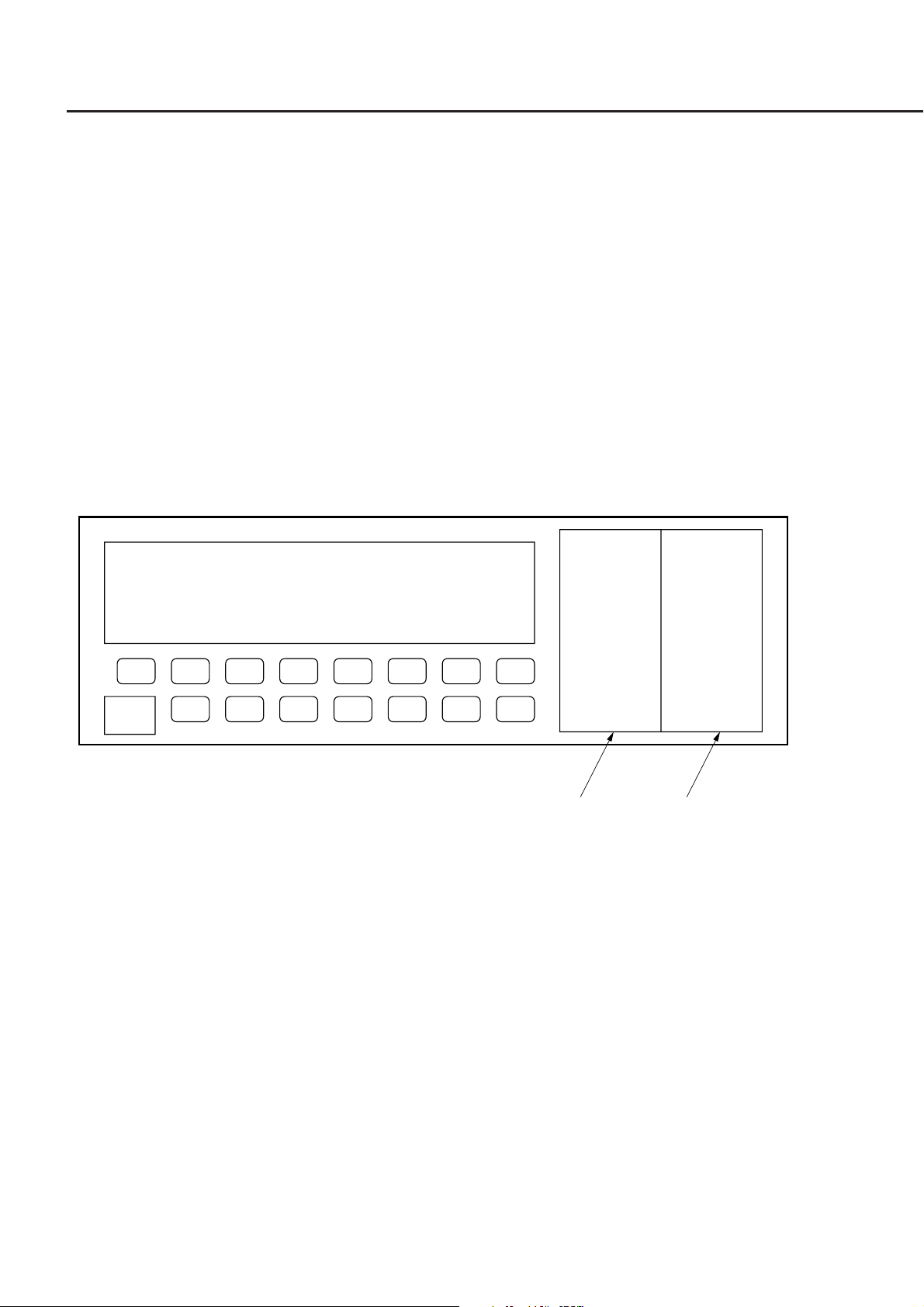
1.3 Channel Numbers of the Unit
Up to two units can be mounted on the MT9810A. There are commands that specify the channel number to which the
unit is mounted. The left channel is Channel 1 and the right channel is Channel 2 as seen from the front.
1-2.
Channel1 Channel2

Section 2 How to Connect
This section explains how to connect GPIB and RS-232C cables between the MT9810A Optical Test Set and external
devices such as a host computer, personal computer, and printer. This section also explains how to set the interfaces of
the MT9810A.
2.1 Connecting Device Using a GPIB Cable ........................... 2-2
2.1.1 Setting the Interface for the Connection Port ...... 2-2
2.1.2 Confirming and Setting the Address .................... 2-3
2.2 Connecting a Device Using an RS-232C Cable ................ 2-4
2.2.1 RS-232C Interface Signal Connection Diagrams 2-5
2.2.2 Setting the Interface of the Connection Port ........ 2-7
2.2.3 Setting RS-232C Interface Conditions ................. 2-7
2.3 Default Value ...................................................................... 2-8
2-1
Section 2 How to Connect
(
)
2.1 Connecting Device Using a GPIB Cable
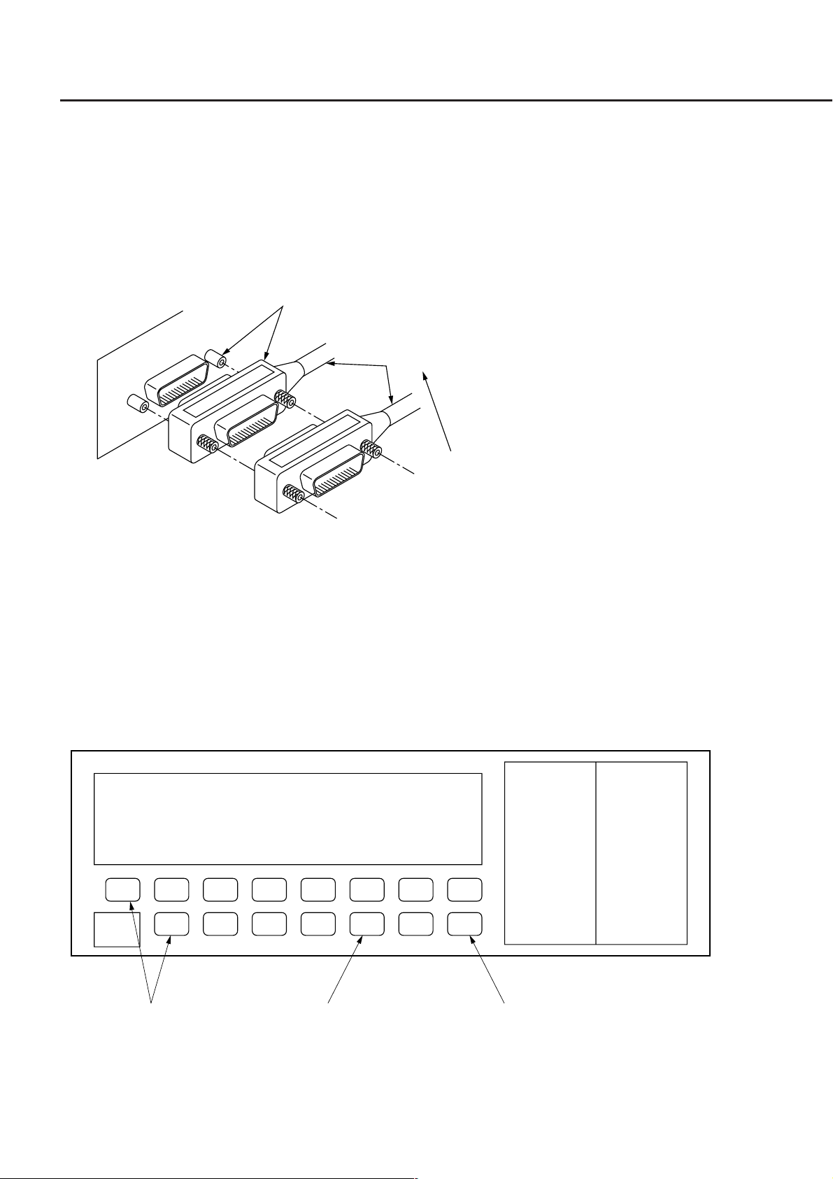
The MT9810A has a GPIB cable connector mounted on the back panel. Be sure to connect the GPIB cable before
turning on the power.
A maximum of 15 devices, including a controller, can be connected to one system. Connect these device in accordance
with the conditions shown in the following figure.
GPIB
Connector
GPIB
GPIB
Cable
Total cable length ≤20 m
Device-to-device cable length ≤4 m
Number of connectable devices <15
2.1.1 Setting the Interface for the Connection Port
Set the interface of the connection port to GPIB. The setting method is shown below.
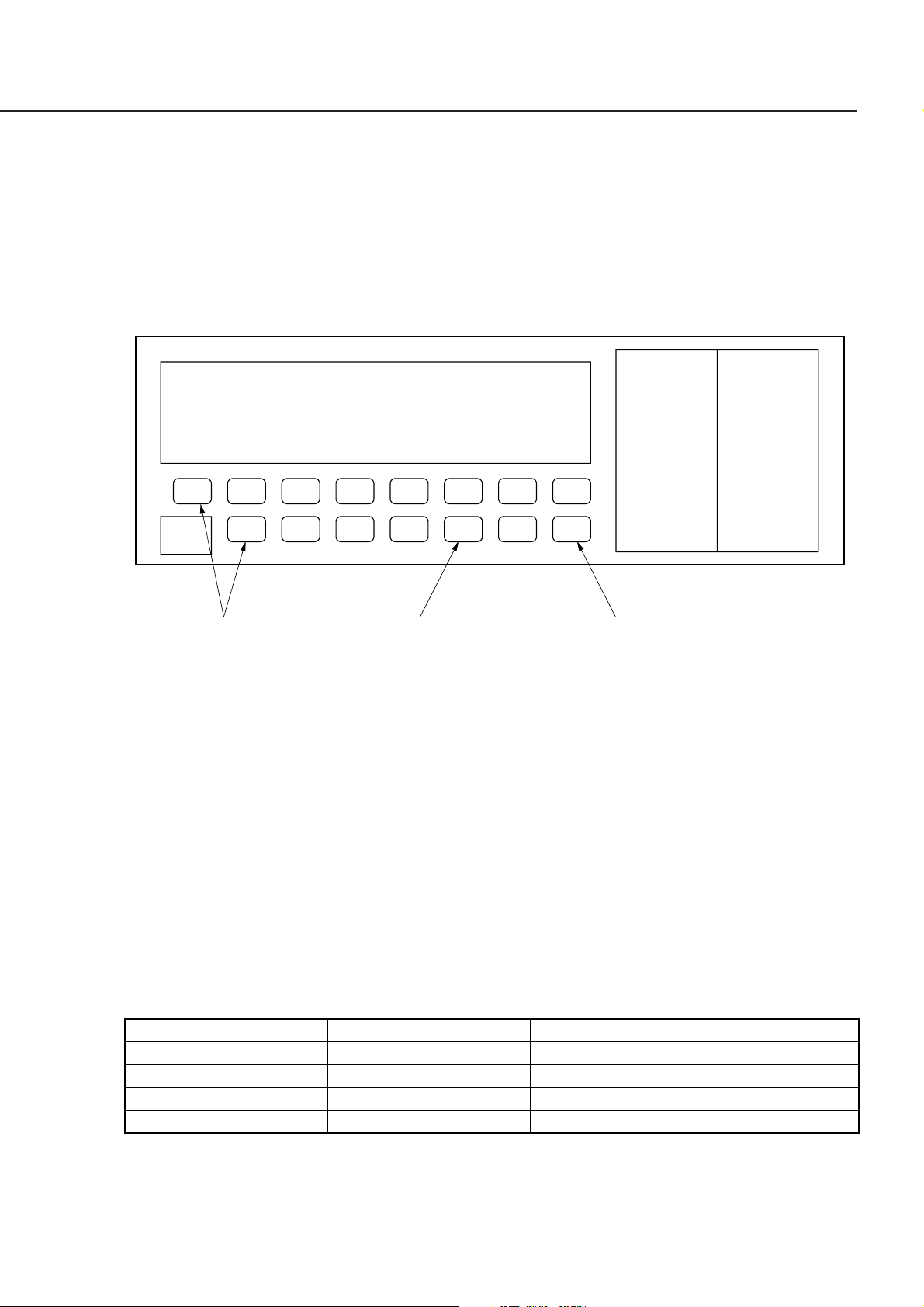
(1) Select "Remote Interface" with the System key.
(2) Switch to "GPIB" with the Select key.
(3) Enter the setting by pressing the Enter key.
2-2
Shift+Prmtr
(2) Select(1) System
(3) Enter

(
)
2.1 Connecting Device Using a GPIB Cable
2.1.2 Confirming and Setting the Address
Be sure to set the GPIB address of the MT9810A after turning on the power. Set the address using the front panel with
the MT9810A set to the local mode.
(1) Select "GPIB ADDRESS" with the System key.
(2) Specify the address with the ↑ and ↓ keys. (The input address range is from 0 to 30.)
(3) Enter the setting by pressing the Enter key.
(1) System
Shift+Prmtr
(3) Enter(2) ↓(2) ↑
2-3
Section 2 How to Connect
2.2 Connecting a Device Using an RS-232C Cable
The MT9810A has an RS-232C connector mounted on the back panel.
NOTE:
RS-232C connectors are available in 9-pin and 25-pin types. The 9-pin type is usually used for DOS/V per-
sonal computers, while the 25-pin type is usually used for the NEC PC9801/PC9821 Series. Before purchas-
ing an RS-232C cable, check the type of the RS-232C connector on the external device. The following two
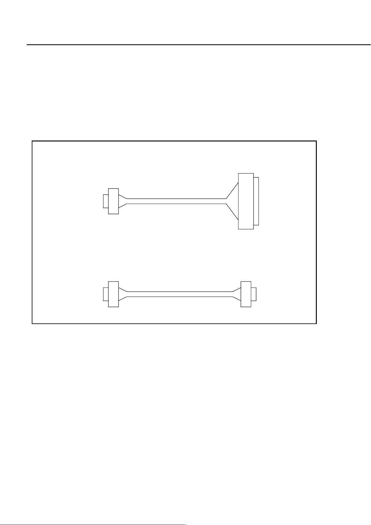
types of RS-232C cables are available as application parts for this product.
• RS-232C cable (for 25-pin type personal computer)
(Personal computer side)(MT9810A side)
D-sub,
9-pin,
Female
• RS-232C cable (for DOS/V personal computer)
D-sub,
9-pin,
Female
Length = 1 m
Length = 1 m
D-sub,
25-pin,
Male
(Personal computer side)(MT9810A side)
D-sub,
9-pin,
Female
2-4
2.2 Connecting a Device Using an RS-232C Cable
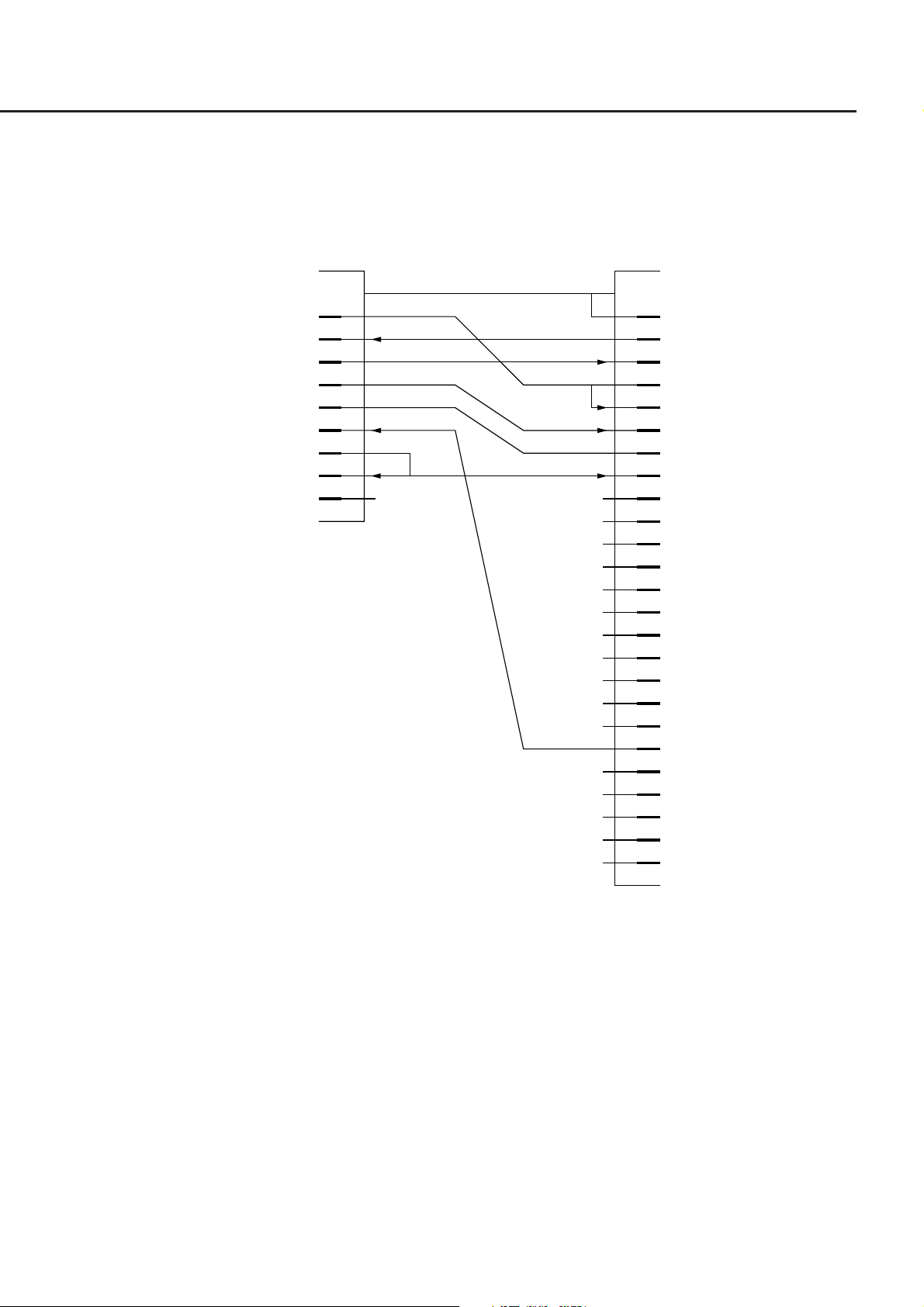
2.2.1 RS-232C Interface Signal Connection Diagrams
The following diagram shows the connection of RS-232C interface signals between the MT9810A and a personal
computer.
Personal computerMT9810A
GND
CD (NC) 1
RD 2
TD 3
DTR (NC) 4
GND 5
DSR (NC) 6
RTS 7
CTS 8
RI (NC) 9
D-sub, 9-pin, female
D-sub, 25-pin, male
GND
1 GND
2SD
3RD
4RS
5CS
6DR
7 GND
8CD
9NC
10 NC
11 GND
12 NC
13 GND
14 GND
15 ST2
16 NC
17 RT
18 NC
19 NC
20 ER
21 NC
22 NC
23 NC
24 ST1
25 NC
Connection to the external computer with a D-sub 25-pin interface
2-5

Section 2 How to Connect
Personal computerMT9810A
GND
CD (NC) 1
RD 2
TD 3
DTR (NC) 4
GND 5
DSR (NC) 6
RTS 7
CTS 8
RI (NC) 9
D-sub, 9-pin, female D-sub, 9-pin, female
Connection to the DOS/V personal computer
GND
(1CD
(2RD
(3TD
( 4 DTR
( 5 GND
( 6 DSR
(7RTS
( 8 CTS
(9RI
2-6
(
)
Item System key Setting value
Baud rate
Stop bit
Parity bit
Character length
RS-232C Baudrate
RS-232C StopBit
RS-232C ParityBit
RS-232C Character
1200/2400/4800/9600/14400/19200 bps
1/2 bit
ODD/EVEN/NONE
7/8 bit
2.2 Connecting a Device Using an RS-232C Cable
2.2.2 Setting the Interface of the Connection Port
Set the interface of the connection port to RS-232C. The setting method is shown below.
(1) Select "Remote Interface" with the System key.
(2) Switch the interface to "RS-232C" with the Select key.
(3) Enter the setting by pressing the Enter key.
(2) Select(1) System
Shift+Prmtr
(3) Enter
2.2.3 Setting RS-232C Interface Conditions
Set the interface conditions for the RS-232C port of MT9810A to match the interface conditions of the connected
external device. The setting method is shown below.
(1) Select the setting items with the System key.
(2) Specify the setting values with the Select key.
(3) Enter the setting by pressing the Enter key.
The setting items are shown in the Table 2-1.
Table 2-1
2-7

Section 2 How to Connect
2.3 Default Value
The factory-set values are shown in the Table 2-2.
Setting item Default value
Remote interface
GPIB address
RS-232C baud rate
RS-232C stop bit
RS-232C parity bit
RS-232C character length
Table 2-2
GPIB
15
9600 bps
1 bit
Even
8 bits
2-8.

Section 3 Specifications
This section explains the GPIB standard, RS-232C standard, and device message list of the MT9810A Optical Test Set.
3.1 GPIB Specifications ............................................................ 3-2
3.2 RS-232C Specifications ..................................................... 3-2
3.3 Device Message List .......................................................... 3-3
3.3.1 IEEE 488.2 common commands and the commands
supported by the MT9810A .................................. 3-5
3.3.2 Device Message List ............................................ 3-6
3-1

Section 3 Specifications
3.1 GPIB Specifications
The GPIB Specifications of the MT9810A is summarized in the Table 3-1.
Table 3-1
Item Specifications value and description
Function
Interface functions
Conforms to IEEE 488.2.
MT9810A can be controlled from an external controller.
SH1: All of source handshake functions are supported.
Data send timing is controlled.
AH1: All of acceptor handshake functions are supported.
Data receive timing is controlled.
T6: Basic talker functions are supported. A serial port function is supported.
A talk-only function is not supported. The function of releasing the talker
with MLA is supported.
L4: Basic listener functions are supported. A listen-only function is not sup-
ported. The function of releasing the listener by MTA is supported.
SR1: All of service request/status byte functions are supported.
RL1: All of remote/local functions are supported.
A local lockout function is supported.
PP0: A parallel poll function is not supported.
DC1: All of device clear functions are supported.
DT0: A disk trigger function is not supported.
C0: A controller function is not supported.
A controller function is performed during external plot output.
3.2 RS-232C Specifications
The RS-232C Specifications of the MT9810A is summarized in the Table 3-2.
Table 3-2
Item Specifications
Function
Communication method
Communication control method
Baud rate
Data bits
Parity
Start bits
Stop bits
Connector
Control from external controller
Asynchronous (start-stop), half-duplex
No flow control
1200, 2400, 4800, 9600, 14400, 19200 bps
7 bits, 8 bits
Odd parity (ODD), even parity (EVEN), non-parity (NON)
1 bit
1 bit, 2 bits
D-sub 9-pin connector, male
3-2
3.3 Device Message List
3.3 Device Message List
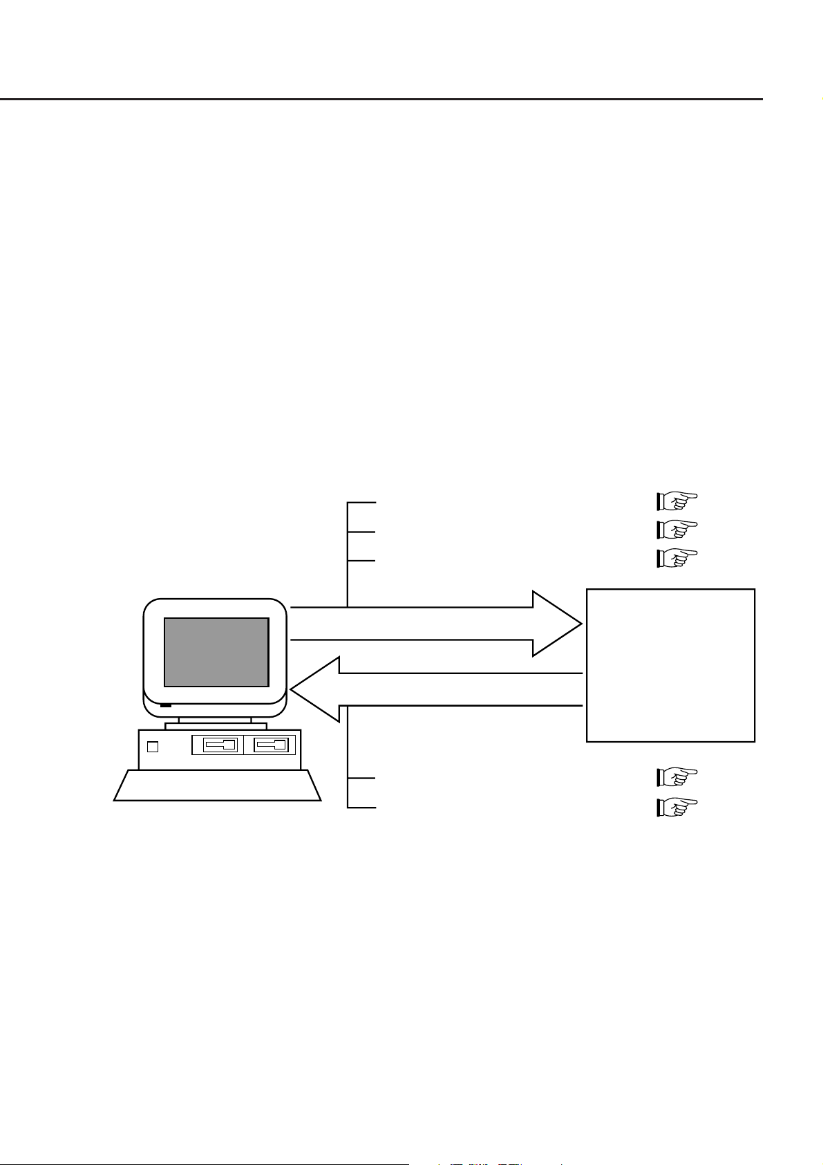
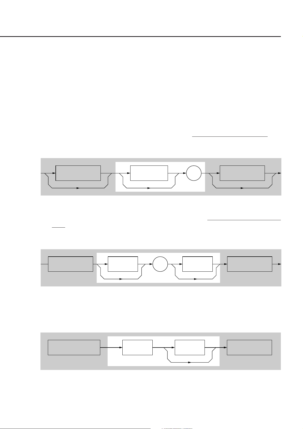
Device messages are data messages which are transferred between a controller and the devices. These messages are
classified into program messages and response messages.
Program messages are ASCII messages transferred from a controller to the devices. Program messages are further
classified into program commands and program queries. These two types of commands are explained later in this
manual.
Program commands include device-dependent commands which are exclusively used for controlling the MT9810A
and IEEE 488.2 common commands. IEEE 488.2 common commands are program commands which are commonly
applicable to other IEEE 488.2-ready measuring instruments (including the MT9810A) on the GPIB interface bus.
Program queries are commands used to get response messages from devices. Program queries must be transferred
from a controller to a device in advance so that the controller can receive response messages from the device later.
Response messages are ASCII data messages which are transferred from a device to a controller. Among response
messages, status messages, and response messages corresponding to program queries are listed later in this manual.
• Program commands Section 5
• Program queries Section 5
• IEEE488.2 common commands Section 7
Controller
Program message
Responce message
• Status message Section 8
• Responce message Section 6
In program and response messages, numeric data may end with a suffix (unit).
Device
3-3

Section 3 Specifications
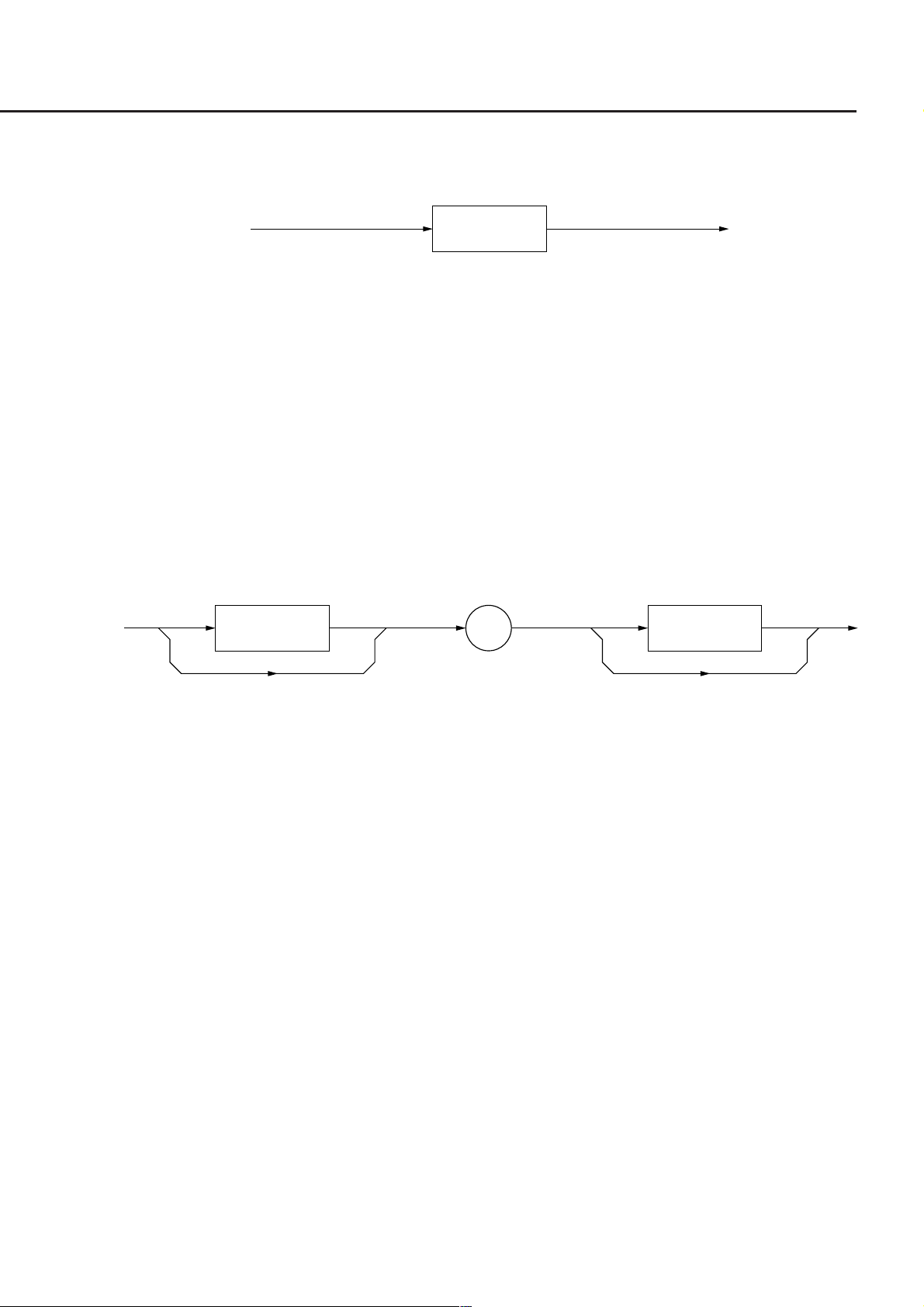
The above messages are transferred through the device input/output buffer. The output buffer is also called an output
queue. A brief description of the output buffer is given below.
Input buffer
Input buffer is an FIFO (first in first out) type memory area, that stores DABs (program and query messages) tempo-
rarily before analysis of syntax and execution.
The input buffer size of the MT9810A is 256 bytes.
Output queue
Output queue is an FIFO-type queue memory area, that stores all DABs (response messages) output from a device to a
controller until those messages are read by the controller.
The output queue size of the MT9810A is 256 bytes.
3-4

3.3 Device Message List
3.3.1 IEEE 488.2 common commands and the commands supported by the MT9810A
The 39 common commands specified by IEEE 488.2 standard is shown in the Table 3-3. Among these commands, the
commands supported by the MT9810A are marked with the check marks (√).
Table 3-3
Mnemonic Fully spelled out command name
∗ADD
∗CAL
∗CLS
∗DDT
∗DDT?
∗DLF
∗DMC
∗EMC
∗EMC?
∗ESE
∗ESE?
∗ESR?
∗GMC?
∗IDN?
∗IST?
∗LMC?
∗LRN?
∗OPC
∗OPC?
∗OPT?
∗PCB
∗PMC
∗PRE
∗PRE?
∗PSC
∗PSC?
∗PUD
∗PUD?
∗RCL
∗RDT
∗RDT?
∗RST
∗SAV
∗SRE
∗SRE?
∗STB?
∗TRG
∗TST?
∗WA I
Accept Address Command
Calibration Query
Clear Status Command
Define Device Trigger Command
Define Device Trigger Query
Disable Listener Function Command
Define Macro Command
Enable Macro Command
Enable Macro Query
Standard Event Status Enable Command
Standard Event Status Enable Query
Standard Event Status Register Query
Get Macro contents Query
Identification Query
Individual Status Query
Learn Macro Query
Learn Device Setup Query
Operation Complete Command
Operation Complete Query
Option Identification Query
Pass Control Back Command
Purge Macro Command
Parallel Poll Register Enable Command
Parallel Poll Register Enable Query
Power On Status Clear Command
Power On Status Clear Query
Protected User Data Command
Protected User Data Query
Recall Command
Resource Description Transfer Command
Resource Description Transfer Query
Reset Command
Save Command
Service Request Enable Command
Service Request Enable Query
Read Status Byte Query
Trigger Command
Self Test Query
Wait to Continue Command
Standardized by IEEE 488.2
Optional
Optional
Required
Optional
Optional
Optional
Optional
Optional
Optional
Required
Required
Required
Optional
Required
Optional
Optional
Optional
Required
Required
Optional
Other than C0: Required
Optional
Optional
Optional
Optional
Optional
Optional
Optional
Optional
Optional
Optional
Required
Optional
Required
Required
Required
DT1: Required
Required
Required
Supported by MT9810A
√
√
√
√
√
√
√
√
√
√
√
√
√
√
NOTE:
IEEE 488.2 commands always begin with an asterick (∗). Refer to the Section 7 "Common Commands" for more details.
3-5

Section 3 Specifications
3.3.2 Device Message List
The device message list unique to the MT9810A is shown in the Table 3-4, 3-5 and 3-6. There are two types of
commands: HP commands and SCPI-compliant Anritsu original commands. The types of commands are also shown in
the table.
Table 3-4 Main frame
Function Command HP
Brightness
Display ON/OFF
Calendar
Time
Buzzer
Header
Inserted unit
Error
DISPlay:BRIGhtness
DISPlay[:STATe]
SYSTem:DATE
SYSTem:TIME
SYSTem:BEEPer:STATe
SYSTem:COMMunicate:GPIB:HEAD
SYSTem:COMMunicate:SERial:HEAD
SYSTem:CHANnel:STATe
SYSTem:ERRor
SCPI Reference
√
√
√
√
√
√
√
√
√
Section 9.1.1
Section 9.1.2
Section 9.1.7
Section 9.1.9
Section 9.1.3
Section 9.1.5
Section 9.1.6
Section 9.1.4
Section 9.1.8
3-6

Table 3-5 Optical sensor
3.3 Device Message List
Function Command HP
Zero-set
Calibration factor
Auto range
Manual range
Reference value
Displays the reference value
Reference measurement
Reference selection
Unit
Wavelength
Unit of wavelength
Measurement data
The number of averaging
Auto bandwidth
Bandwidth
Modulation frequency
Measurement interval
The number of measurement
Logging
Statistical measurement
Measurement stop
Logging data
Logging data information
Maximum value
Minimum value
Difference between maximum
and minimum values
Measurement conditions
High-speed transfer mode start
High-speed transfer mode stop
SENSe[1|2]:CORRection:COLLect:ZERO
SENSe[1|2]:CORRection[:LOSS:[:INPut[:MAG
Nitude]]]
SENSe[1|2]:POWer:RANGe:AUTO
SENSe[1|2]:POWer:RANGe:[UPPer]
SENSe[1|2]:POWer:REFerence
SENSe[1|2]:POWer:REFerence:DISPlay
SENSe[1|2]:POWer:REFernce:STATe
SENSe[1|2]:POWer:REFernce:STATe:RATio
SENSe[1|2]:POWer:UNIT
SENSe[1|2]:POWer:WAVelength
SENSe[1|2]:POWer:WAVelength:UNI
FETCh[1|2][:SCALar]:POWer[:DC]
SENSe[1|2]:AVERage:COUNt
SENSe[1|2]:BANDwidth:AUTO
SENSe[1|2]:BANDwidth
SENSe[1|2]:FILTer:BPASs:FREQuency
SENSe[1|2]:POWer:INTerval
SENSe[1|2]:TRIGger:COUNt
SENSe[1|2]:INITiate[:IMMediate]
SENSe[1|2]:TRIGger[:SEQuence][:IMMediate]
ABORt[1|2]
SENSe[1|2]:MEMory:DATa
SENSe[1|2]:MEMory:DATa:INFO
SENSe[1|2]:FETCh[:SCALar]:POWer[:DC]:MAXimum
SENSe[1|2]:FETCh[:SCALar]:POWer[:DC]:MINimum
SENSe[1|2]:FETCh[:SCALar]:POWer[:DC]:PTPeak
SENSe[1|2]:MEMory:COPY[:NAME]
READ[1|2]
READ[1|2]:ABORt
SCPI
√
√
√
√
√
√
√
√
√
√
√
√
√
√
√
√
√
√
√
√
√
√
√
√
√
√
√
√
√
Reference
Section 9.2.6
Section 9.2.7
Section 9.2.17
Section 9.2.18
Section 9.2.19
Section 9.2.20
Section 9.2.21
Section 9.2.22
Section 9.2.23
Section 9.2.24
Section 9.2.25
Section 9.2.2
Section 9.2.3
Section 9.2.5
Section 9.2.4
Section 9.2.11
Section 9.2.16
Section 9.2.26
Section 9.2.12
Section 9.2.27
Section 9.2.1
Section 9.2.14
Section 9.2.15
Section 9.2.8
Section 9.2.9
Section 9.2.10
Section 9.2.13
Section 9.2.28
Section 9.2.29
3-7

Section 3 Specifications
Table 3-6 Light source
Function Command HP
Modulation frequency
Attenuation
Optical output
Wavelength
Unit of wavelength
Measurement condition
In the portion described as [1|2], enter the channel number into which the target unit is inserted (1 or 2). The brackets
([ ]) are not required.
When you send the LIGHT SOURCE COMMAND to OPTICAL SENSOR, the command error occurs.
At the opposite case (send the OPTICAL SENSOR COMMAND to LIGHT SOURCE), the command error occures
too.
SOURce[1|2]:AM[:INTerval]:FREQuency
SOURce[1|2]:POWer:ATTenuation
SOURce[1|2]:POWer:STATe
SOURce[1|2]:POWer:WAVelength
SOURce[1|2]:POWer:WAVelength:UNIT
SOURce[1|2]:MEMory[1|2]:COPY[:NAME]
SCPI
√
√
√
√
√
√
Reference
Section9.3.1
Section9.3.3
Section9.3.4
Section9.3.5
Section9.3.6
Section9.3.2
3-8.

Section 4 Initial Setting
Initialization of the GPIB interface system is devided into three levels. At level 1, "bus initialization" is performed to
place the system bus in the idle state. At level 2, "message exchange initialization" is performed to enable devices to
receive program messages. At level 3, "device initialization" is performed to initialize device-dependent functions.
At these three initialization levels, preparations are made for starting devices.
4.1 Initialization of Bus by IFC Statement ................................ 4-3
4.2 Initialization of Message Exchange by DCL and SDC Bus
Commands ......................................................................... 4-5
4.3 Initialization of Devices by ∗RST Command ...................... 4-7
4.4 Device States at Power-ON ............................................... 4-8
4.4.1 Items not changes at Power-ON .......................... 4-9
4.4.2 Items related to PSC flag ..................................... 4-9
4.4.3 Items that change at Power-ON ........................... 4-9
4-1

Section 4 Initial Setting
IEEE 488.2 specifies the initialization of the GPIB system as described in the Table 4-1.
Table 4-1
Level
1
2
3
When controlled from a controller via the RS-232C interface port, the MT9810A can use the "device initialization"
function (level 3). However, it cannot use "bus initialization" (level 1) and "message exchange initialization" (level 2)
functions.
When controlled from a controller via a GPIB interface bus, the MT9810A can use all the above initialization functions
(levels 1 to 3).
Initialization type
Bus initialization
Message exchange
initialization
Device initialization
Overview
Interface functions of all devices connect-
ed to the bus are initialized by an IFC
message from a controller.
Message exchange is initialized and the
function of reporting completion of opera-
tion to the controller is disabled. This ini-
tialization can be ferformed either for all
devices on the GPIB using GPIB bus com-
mand DCL, or only for the specified
devices using a GPIB bus command SDC.
Only the specified devices on the GPIB
are initialized to the known states with an
∗RST command irrespective of the past
use state.
Combination and priority of levels
This level may be combined with
other levels. However, initializa-
tion at level 1 must be performed
before initialization at other lev-
els.
This level may be combined
withother levels. However, ini-
tialization at level 2 must be per-
formed before initialization at
level 3.
This level may be combined with
other levels. However, initializa-
tion at level 3 must be performed
after initialization at levels 1 and 3.
4-2
4.1 Initialization of Bus by IFC Statement
Initialization by IFC
√
√
√
√
∆
√
Function
Source handshake
Acceptor handshake
Talker or extended talker
Listener or extended listener
Service request
Remote/local
Parallel/poll
Device clear
Device trigger
Controller
No
1
2
3
4
5
6
7
8
9
10
Symbol
SH
AH
T or TE
L or LT
SR
RL
PP
DC
DT
C
(1) Format
IFC ∆ select-code
(2) Explanation
This function can be used when the MT9810A is controlled from a controller via a GPIB interface bus.
On the GPIB corresponding to the specified select code, the IFC line is activated for about 100 µs (as electrically
set at the low level). When IFC is executed, interface functions of all devices connected to the GPIB bus line
corresponding to the specified select code are initialized. Only the system controller can send this command.
"Initialization of interface functions" refers to the processing in which controller-set device interface functions
(talker, listener, etc.) are reset to their initial states. Functions marked with the check marks (√) in the following
table are initialized. The function marked with a triangle (∆) is initialized partially.
Table 4-2
IFC
If the IFC statement is True (the IFC line is set at the low level through execution of the IFC statement), initialization
is not performed at levels 2 and 3. Therefore, device operating states are not affected.
4-3

Section 4 Initial Setting
The examples of device states set by the IFC statement are shown in the Table 4-3.
Table 4-3
Item Device state
Talker/listener
Controller
Return of control right
Devices issuing service
request
Devices in remote state
All talkers and listeners are set in the idle state (TIDS, LIDS) within 100 µs.
If the controller is not active (SACS: System control ACtive State), it enters the
idle state, or CIDS, (Controller IDle State) within 100 µs.
If the system controller (the first device on the GPIB which is used as a controller)
has granted the control right to another device when IFC is executed, the control
right is returned to the system controller. Generally, pressing the RESET key on
the system controller allows an IFC message to be output from the system con-
troller.
The state in which an SRQ message is issued by a device (the SRQ line is set at
the LOW level by the device) is not canceled, but the state in which all devices on
the system bus are placed in the serial poll mode by the controller is canceled.
For the devices currently in the remote state, the remote state is not canceled by
the IFC message.
4-4

4.2 Initialization of Message Exchange by DCL and
SDC Bus Commands
(1) Format
DCL ∆ select-code [primary-address] [secondary-address]
(2) Explanation
This function can be used when the MT9810A is controlled by a controller via the GPIB interface bus.
This statement initializes message exchange for all device on the GPIB corresponding to the specified select code
or only for the specified devices.
The purpose of message exchange is to allow the controller to send new commands when the controller cannot
control message-exchange-related parts inside the devices due to execution of programs although it is not neces-
sary to change the panel settings.
(3) When only a select code is specified
Message exchange is initialized for all the devices on the GPIB corresponding to the specified select code. DCL
issues a DCL (Device Clear) bus command to the GPIB.
DCL
(4) When an address is also specified
Message exchange is initialized only for the specified device. Listeners on the GPIB corresponding to the speci-
fied select code are canceled, only the specified device is set as a listener, and an SDC (Selected Device Clear)
bus command is issued.
4-5

Section 4 Initial Setting
(5) Items subject to initialization of message exchange
Table 4-4
Item Device state
Input buffer and output queue
Syntax analysis, execution con-
trol, and response generation parts
Device commands including ∗RST
Paired parameter/program
message
∗OPC command processing
∗OPC? query processing
The settings are cleared.
The functions are reset.
All commands interfering with execution of these commands are cleared.
All commands and queries of which execution has been suspended due to paired
parameters are discarded.
The specified device is set in the OCIS (Operating Complete Command Idle State).
The operation complete bit cannot be set in the standard event status register.
The specified device is set in the OQIS (Operating Complete Query Idle State).
The operation complete bit 1 cannot be set in the output queue. The MAV (Mes-
sage Available) bit is cleared.
Section 7
Section 7
Automatic system configura-
tion
Device function
The following operations using DCL are prohibited.
(a) Changing the current device settings and stored data
(b) Interrupting front panel I/O
(c) Changing status bits other than the MAV bit when clearing the output queue
(d) Affecting or interrupting the device operation currently being performed
(6) Orders of issuing GPIB bus commands using DCL statements
Orders of issuing GPIB bus commands using DCL, SDC statements are summarized in the Table 4-5.
Statement
DCLselect-code
DCLdevice-number
UNL, DCL
UNL, LISTEN address, [secondary-address], SDC
∗ADD and ∗DLF common commands are invalidated. (The MT9810A does not
support these commands.)
All parts related to message exchange are set in the idle state. The device waits for
a message from the controller.
Table 4-5
Bus command issue order (ATN line: Low level)
Data (ATN line: High level)
4-6

4.3 Initialization of Devices by ∗RST Command
Item Device state
Device-dependent functions
and states
∗OPC command processing
∗OPC? query processing
Macro command
The specified device is set in a known state irrespective of its history. (Refer to the
lists on the following pages.)
The specified device is set in the OCIS (Operating Complete Command Idle State).
The operation complete bit cannot be set in the standard event status register.
Section 7
The specified device is set in the OQIS (Operating Complete Query Idle State).
The operation complete bit 1 cannot be set in the output queue. The MAV (Mes-
sage Available) bit is cleared.
Section 7
Macro operation is disabled, and sets the state in which macro commands cannot
be accepted. The returnes the macro definitions to the designer's state.
(1) Format
∗RST
(2) Explanation
The ∗RST (Reset) command is one of the IEEE 488.2 common command, which is used to reset a specified
device at level 3.
Generally, devices are set in various states using device-dependent commands (device messages). Among these
commands, the ∗RST command is used to reproduce a known state of a device. Completion of device operation
is invalidated like level 2.
(3) Specification of device number in WRITE statement
The device at the specified address is initialized at level 3.
(4) Items subject to device initialization
∗RST
NOTES:
∗RST command does not affect the following items:
1. IEEE 488.1 interface state
2. Device address
3. Output queue
4. Service request enable register
5. Standard event status enable register
6. Power-on-status-clear flag setting
7. Calibration data affecting device standard
8. RS-232C interface condition
Table 4-6
4-7

Section 4 Initial Setting
4.4 Device States at Power-ON
When the power is turned on:
(1) The MT9810A is restored to the last Power-OFF state.
(2) The input buffer and output queue are cleared.
(3) Syntax analysis, execution control, and response generation parts are reset.
(4) The device is set in the OCIS.
(5) The device is set in the OQIS.
(6) The MT9810A does not support a ∗PSC command. Therefore, the standard event status register and standard
event status enable register are cleared.
Events are recorded after being cleared.
States (2) to (5) are set except when the power is turned on. The following diagram describes these states.
• Input buffer
• Output queue
pon
∨
dcas
∨
∗CLS
∨
∗RST
pon∨dcas
OQIS
Operation
Complete
Query
Idle State
• Syntax analysis
part
• Execution
control part
• Response
generation part
pon
∨
dcas
∨
∗CLS
∨
∗RST
pon∨dcas
OCIS
ResetClear
Operation
Complete
Command
Idle State
4-8

4.4 Device States at Power-ON
4.4.1 Items not changes at Power-ON
(1) Address
(2) Associating calibration data
(3) Data and states are changed by the responses to the following common query commands.
∗IDN? ........... Refer to the Section 7 "Common Commands"
∗OPT? .......... Refer to the Section 7 "Common Commands"
∗PSC? ........... Not supported by the MT9810A
∗PUD? .......... Not supported by the MT9810A
∗RDT? .......... Not supported by the MT9810A
4.4.2 Items related to PSC flag
When the PSC (Power-ON status clear) flag is False, the service request enable register, standard event status enable
register, and parallel poll enable register are not affected. Refer to the Section 8.3 "Enabling the SRQ" for the service
request enable register, and refer to the Section 8.4 "Standard Event Status Register" for the standard event status
enable register
When the PSC flag is Low level (True) or the ∗PSC command has not been executed, the above registers are cleared.
NOTE:
The PSC command is not supported by the MT9810A.
4.4.3 Items that change at Power-ON
(1) Current device function state
(2) Status information
(3) ∗SAV/∗RCL register (Not supported by the MT9810A)
(4) Macro definition made with a ∗DDT command (Not supported by the MT9810A)
(5) Macro definition made with a ∗DMC command (Not supported by the MT9810A)
(6) Macro enabled with an ∗EMC command (Not supported by the MT9810A)
(7) Address received with a ∗PCB command (Not supported by the MT9810A)
4-9

Section 4 Initial Setting
4-10.

Section 5 Listener Input Formats
Device messages are data messages transferred between the controller and devices, which can be classified into program
messages and response messages. This section explains the formats of the program messages received by listeners.
5.1 Summary of Listener Input Program Message
Syntactical Notation ........................................................... 5-3
5.1.1 Separator, Terminator, and Space Before Header ..... 5-3
5.1.2 General Format of Program Command Message ...... 5-5
5.1.3 General Format of Query Message ..................... 5-6
5.2 Program Message Functional Elements ............................ 5-7
5.2.1 <TERMINATED PROGRAM MESSAGE> ........... 5-7
5.2.2 <PROGRAM MESSAGE TERMINATOR> ........... 5-8
5.2.3 <white space> ...................................................... 5-9
5.2.4 <PROGRAM MESSAGE> .................................... 5-9
5.2.5 <PROGRAM MESSAGE UNIT SEPARATOR> ... 5-10
5.2.6 <PROGRAM MESSAGE UNIT> .......................... 5-10
5.2.7 <COMMAND MESSAGE UNIT>/
<QUERY MESSAGE UNIT> ................................ 5-11
5.2.8 <COMMAND PROGRAM HEADER> ................... 5-12
5.2.9 <QUERY PROGRAM HEADER> ......................... 5-14
5.2.10 <PROGRAM HEADER SEPARATOR> ............... 5-15
5.2.11 <PROGRAM DATA SEPARATOR> ..................... 5-15
5.3 Program Data Format......................................................... 5-16
5.3.1 <CHARACTER PROGRAM DATA> ..................... 5-17
5.3.2 <DECIMAL NUMERIC PROGRAM DATA> ......... 5-18
5.3.3 <SUFFIX PROGRAM DATA> .............................. 5-22
5.3.4 <NON-DECIMAL NUMERIC PROGRAM DATA> ..... 5-25
5.3.5 <STRING PROGRAM DATA> ............................. 5-26
5.3.6 <ARBITRARY BLOCK PROGRAM DATA> ......... 5-27
5.3.7 <EXPRESSION PROGRAM DATA> ................... 5-31
5-1
Section 5 Listener Input Formats
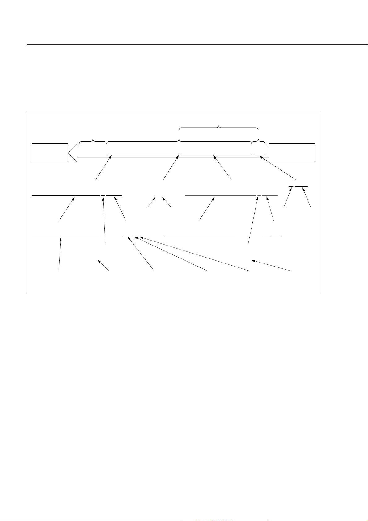
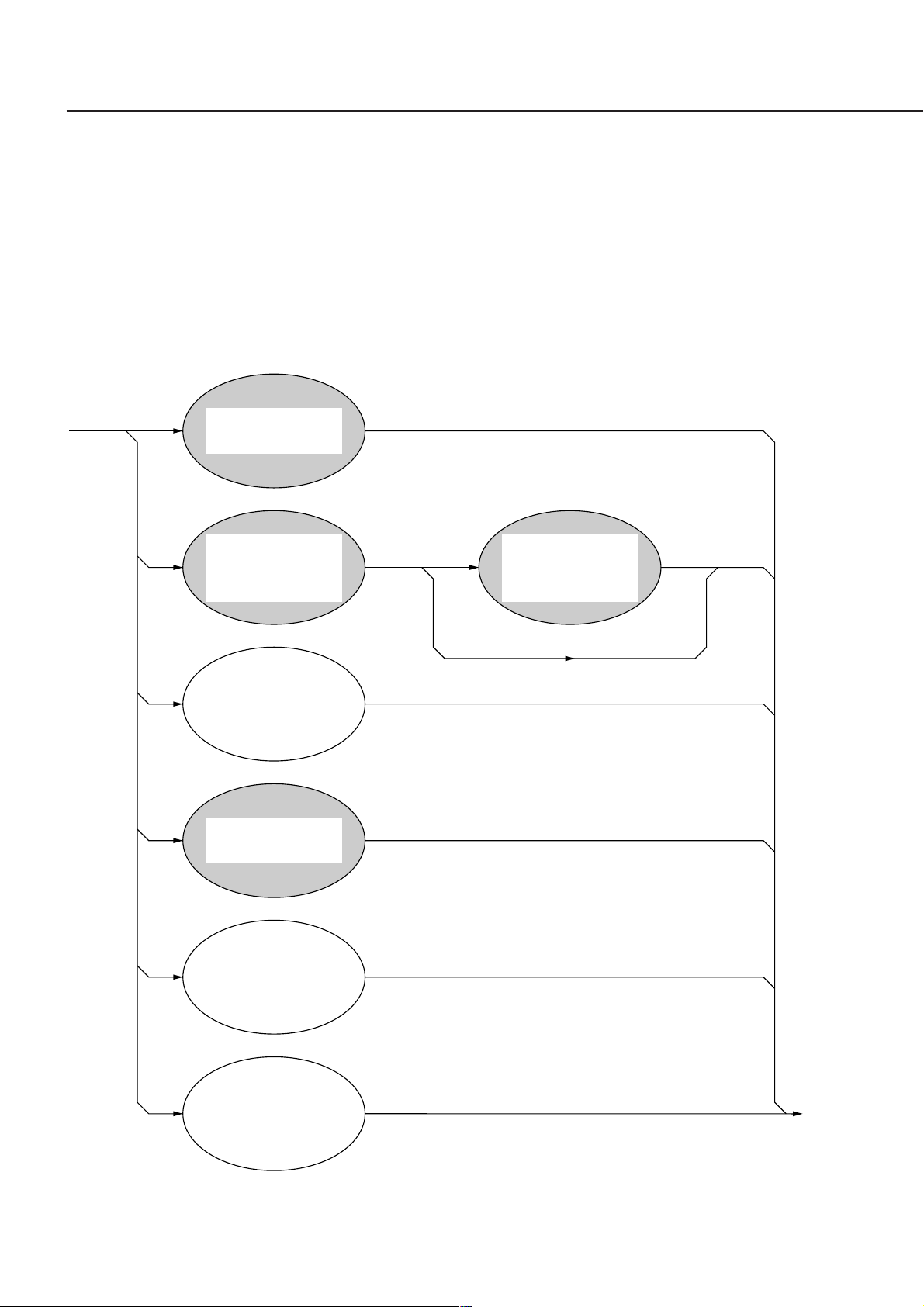
A program message is a sequence of program message units. Each unit is a program command or query.
The following diagram shows how to set the wavelength and measurement range of the power meter unit inserted into
Channel 1 to 1550 nm and –10 dBm. As it explained in the diagram, two program message units
SENSE1:POWER:WAVELENGTH 1550NM and SENSE1:POWER:RANGE:UPPER –10DBM are connected with
the program message unit separator and sent to the device from the controller as one program message.
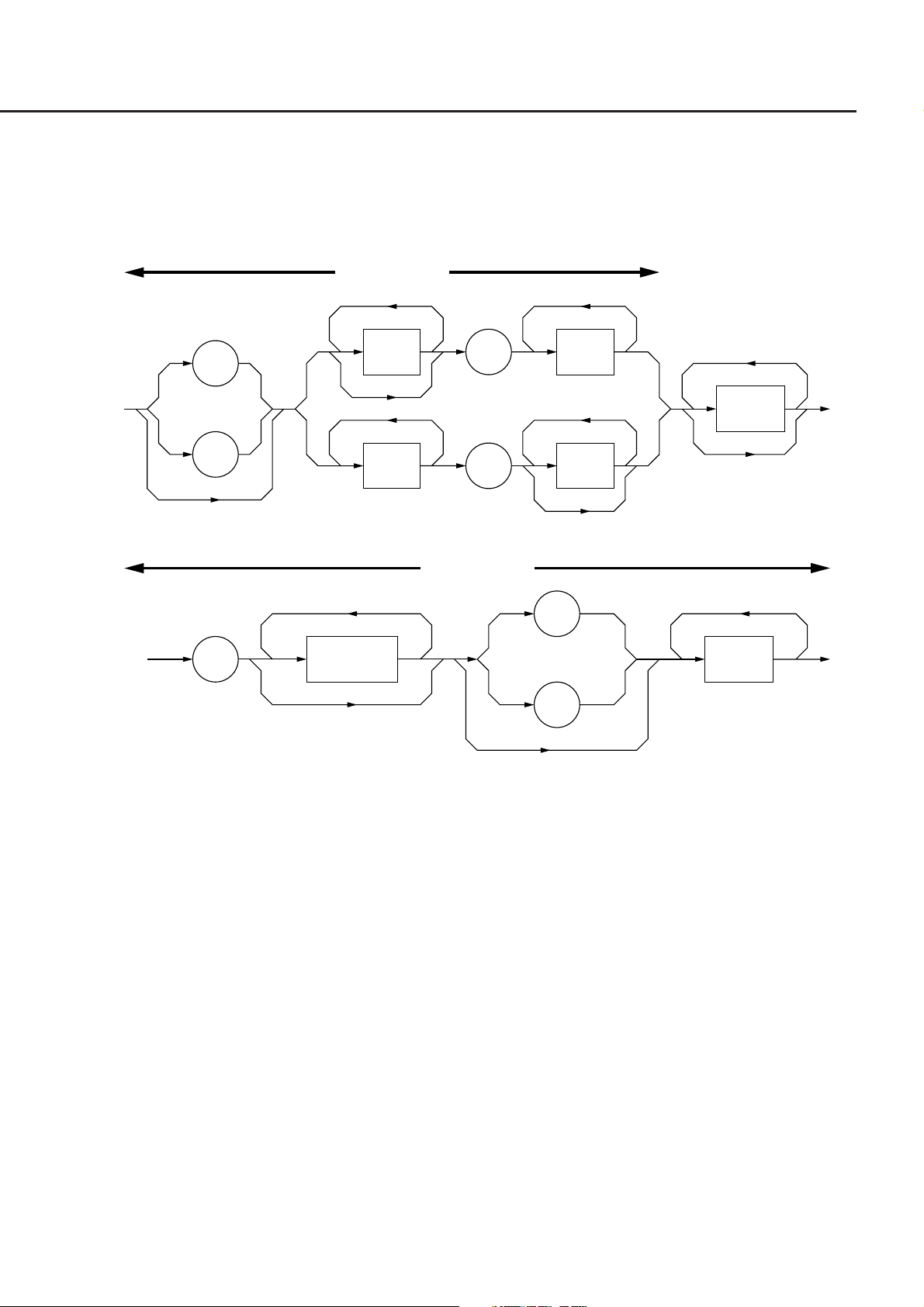
<TERMINATED PROGRAM MESSAGE>
Address15
Listener
Listener address specification
Call Send(0, 15, "SENSE1: POWER: WAVELENGTH 1550NM ; SENSE1: POWER: RANGE: UPPER-10DBM", NLend)
(device)
<PROGRAM MESSAGE UNIT> <PROGRAM MESSAGE UNIT><PROGRAM MESSAGE UNIT SEPARATOR>
SENSE1: POWER: WAVELENGTH 1550NM
<COMMAND PROGRAM HEADER>
SENSE1: POWER: WAVELENGTH
<PROGRAM HEADER SEPARATOR>
sp
<program mnemonic>
SENSE1: POWER: WAVELENGTH
<white space> <decimal numeric program data>
<white space>
<PROGRAM DATA>
1550 N M
<PROGRAM MESSAGE>
SENSE1: POWER: RANGE: UPPER -10DBMsp ;
;
<COMMAND PROGRAM HEADER>
SENSE1: POWER: RANGE: UPPER
<suffix program data>
1550
N
<PROGRAM MESSAGE TERMINATOR>
<white space>
<PROGRAM DATA>
-10 DBM
<PROGRAM HEADER SEPARATOR>
sp
<suffix program data>
M
Talker
(controller)
sp NLend
NL
<white space>
A program message is a sequence of functional elements, the minimum units that can represent functions. In the above
figure, functional elements are indicated by capital characters with them enclosed in < >. Functional elements are
further classified into coding elements which are indicated by lowercase characters with them enclosed in < >.
The chart indicating the route of selection of functional elements is called a functional syntactical chart. The chart
indicating the route of selection of coding elements is called a coding syntactical chart. Refer to the Section 5.1
"Summary of Listener Input Program Message Syntactical Notation" for the program message formats using these
functional and coding syntactical charts.
Coding elements indicate coding of the actual bus which is required to send functional element data byte to a device.
Upon receipt of a functional element data byte, the listener checks whether individual elements follow the coding
syntax rules. If these elements do not follow the rules, the listener causes a command error without regarding the
elements as functional elements.
5-2
5.1 Summary of Listener Input Program Message Syntactical Notation
5.1 Summary of Listener Input Program Message Syn-
tactical Notation
This section gives a general description of program message functional units and program data formats. Refer to the
Section 5.2 "Program Message Functional Elements" for program message functional units and the Section 5.3 "Pro-
gram Data Format" for data formats. (Compound commands and common commands are excluded.)
5.1.1 Separator, Terminator, and Space Before Header
(1) <PROGRAM MESSAGE UNIT SEPARATOR>
Link two or more <PROGRAM MESSAGE UNIT> elements using
<Example> The general format for linking two <PROGRAM MESSAGE UNIT> elements
<PROGRAM
MESSAGE UNIT>
(2) <PROGRAM DATA SEPARATOR>
Separate two or more contiguous pieces of <PROGRAM DATA> using
spaces.
<Example> The general format for separating two pieces of <PROGRAM DATA>
<PROGRAM DATA> <PROGRAM DATA><white space> <white space>
<white space>
,
zero or more spaces and a semicolon.
;
a comma in between zero or more
<PROGRAM
MESSAGE UNIT>
(3) <PROGRAM HEADER SEPARATOR>
Separate <PROGRAM HEADER> and <PROGRAM DATA> using one space and zero or more spaces.
<Example> The general format of single command <PROGRAM HEADER>
<PROGRAM HEADER> <PROGRAM DATA><white space> <white space>
5-3

Section 5 Listener Input Formats
(4) <PROGRAM MESSAGE TERMINATOR>
zero or more spaces and one of NL, EOI, and a combination of NL and EOI at the end of a <PROGRAM
Add
MESSAGE>.
<General format>
NL
<PROGRAM MESSAGE> <white space>
(5) Space before header
Zero or more spaces can precede a <PROGRAM HEADER>.
<General format>
<PROGRAM HEADER> <PROGRAM HEADER SEPARATOR><white space>
∧ END
NL
∧ END
5-4

5.1 Summary of Listener Input Program Message Syntactical Notation
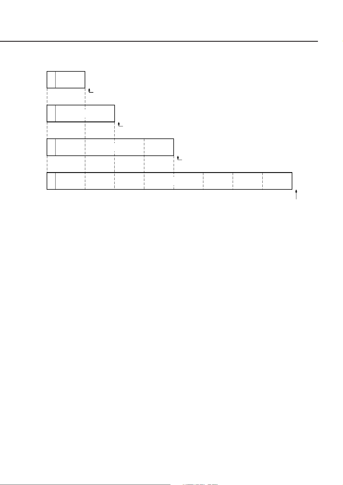
5.1.2 General Format of Program Command Message
(1) Message without data specification
<HR>
HR: COMMAND PROGRAM HEADER
(2) Message with integer data
<HR> NR1
SP
NR1: Integer
(3) Message with real number
<HR> NR2SP
NR2: Real number
(4) Message with fixed or arbitrary character string data (data length ≤ 12 characters)
<HR> character
SP
(5) Message with multiple pieces of program data (starts with NR1)
<HR> NR1 or NR2NR1 or NR2
SP
,
,
5-5

Section 5 Listener Input Formats
(6) Character-only message that can use all ASCII 7-bits
'
<inserted'>
' '
non single
quote char
<HR>
SP
"
<inserted">
"
non single
quote char
<inserted '>: Single ASCII code representing a value 27
non-single quote char: Single ASCII code representing a value other than 27
<inserted ">: Single ASCII code representing a value 22
non-single quote char: Single ASCII code representing a value other than 22
"
5.1.3 General Format of Query Message
Add a question mark (?) at the end of command <PROGRAM HEADER> for a query <PROGRAM HEADER>.
(1) Message without query data specification
<HR>
(2) Message with query data specification
<HR> NR2NR1
SP
'
5-6

5.2 Program Message Functional Elements
5.2 Program Message Functional Elements
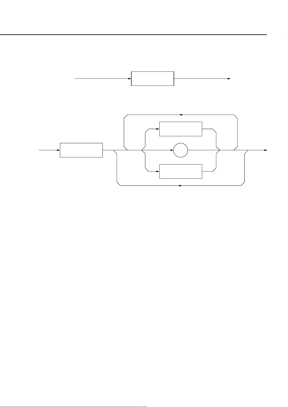
A device accepts a program message by detecting the terminator added at the end of the program message. The
following pages describe the functional elements of the program message.
5.2.1 <TERMINATED PROGRAM MESSAGE>
<TERMINATED PROGRAM MESSAGE> is defined as follows:
<PROGRAM MESSAGE>
Refer to 5.2.4
<TERMINATED PROGRAM MESSAGE> is a data message containing all the necessary functional elements to be
sent from a controller to a device.
To complete the transfer of <PROGRAM MESSAGE>, <PROGRAM MESSAGE TERMINATOR> is added at the
end of <PROGRAM MESSAGE>.
<PROGRAM
MESSAGE TERMINATOR>
Refer to 5.2.2
5-7

Section 5 Listener Input Formats
5.2.2 <PROGRAM MESSAGE TERMINATOR>
<PROGRAM MESSAGE TERMINATOR> is defined as follows:
∧ END
<white space>
Refer to 5.2.3
NL
∧ END
NL
<PROGRAM MESSAGE TERMINATOR> terminates a sequence of one or more fixed-length <PROGRAM MES-
SAGE UNIT> elements.
NL Defined as a single ASCII code byte 0A (decimal 10), which is an ASCII control
character LF (Line Feed) that moves the printing position down one line. Because the
printing starts at a new line, it is also called NL (New Line).
END Sets the EOI line, one of GPIB control buses, at the LOW level (True), generating an
EOI signal.
NOTE:
The CR code is used to return the printing position to the first character position on the same line; however,
most listeners ignore this cord. Some products available on the market uses CR-LF code, so most controllers
are so designed that CR and LF codes are issued in succession.
LF
CR LF
5-8

5.2 Program Message Functional Elements
5.2.3 <white space>
<white space> is defined as follows:
<white space
character>
<white space character> is one of single ASCII code bytes 00 to 09 and 0B to 20 (decimal values 0 to 9 and 11 to 32).
This range includes ASCII control codes and space signals and excepts NL. The device does not regard these codes as
ASCII control codes but the spaces and it skips those cords.
5.2.4 <PROGRAM MESSAGE>
<PROGRAM MESSAGE> is defined as follows:
<PROGRAM MESSAGE
UNIT SEPARATOR>
Refer to 5.2.5
<PROGRAM MESSAGE UNIT>
Refer to 5.2.6
<PROGRAM MESSAGE> is zero, a <PROGRAM MESSAGE UNIT> element, or a sequence of <PROGRAM MES-
SAGE UNIT> elements. A <PROGRAM MESSAGE UNIT> element is a programming command or data which is
sent from a controller to a device.
A <PROGRAM MESSAGE UNIT SEPARATOR> element is used to separate two or more <PROGRAM MESSAGE
UNIT> elements.
5-9

Section 5 Listener Input Formats
5.2.5 <PROGRAM MESSAGE UNIT SEPARATOR>
<PROGRAM MESSAGE UNIT SEPARATOR> is defined as follows:
<white space>
;
<white space> is defined as follows:
<white space character>
Refer to 5.2.3
<PROGRAM MESSAGE UNIT SEPARATOR> divides a sequence of <PROGRAM MESSAGE UNIT> elements
within the range of <PROGRAM MESSAGE>.
A device interprets a semi-colon (;) as the separator between <PROGRAM MESSAGE UNIT> elements. Accord-
ingly, <white space character> placed before and after the semi-colon (;) is ignored, although <white space character>
improves program readability. <white space> following a semi-colon (;) is also used as a <white space> for the next
<PROGRAM HEADER>.
Section 5.2.8
5.2.6 <PROGRAM MESSAGE UNIT>
<PROGRAM MESSAGE UNIT> is defined as follows:
<COMMAND MESSAGE UNIT>
Refer to 5.2.7
<QUERY MESSAGE UNIT>
Refer to 5.2.7
<PROGRAM MESSAGE UNIT> is a single command message received by a device.
It consists of <COMMAND MESSAGE UNIT> or <QUERY MESSAGE UNIT>, which is a single query message.
Refer to the Section 5.2.7 "<COMMAND MESSAGE UNIT>/<QUERY MESSAGE UNIT>" for more details.
5-10

5.2 Program Message Functional Elements
5.2.7 <COMMAND MESSAGE UNIT>/<QUERY MESSAGE UNIT>
<COMMAND MESSAGE UNIT> is defined as follows:
<PROGRAM
DATA SEPARATOR>
Refer to 5.2.11
<COMMAND
PROGRAM HEADER>
Refer to 5.2.8
<PROGRAM
HEADER SEPARATOR>
Refer to 5.2.10
<PROGRAM DATA>
<QUERY MESSAGE UNIT> is defined as follows:
<PROGRAM
DATA SEPARATOR>
Refer to 5.2.11
<QUERY
PROGRAM HEADER>
Refer to 5.2.9
<PROGRAM
HEADER SEPARATOR>
Refer to 5.2.10
<PROGRAM DATA>
When a <PROGRAM HEADER> of <COMMAND MESSAGE UNIT> or <QUERY MESSAGE UNIT> is followed
by <PROGRAM DATA>, a space is inserted between these unit. A <PROGRAM HEADER> indicates the applica-
tion, function, and operation of the program. If a <PROGRAM HEADER> is not followed by <PROGRAM DATA>,
the <PROGRAM HEADER> solely indicates the application, function, and operation to be performed in the device.
Among <PROGRAM HEADER> elements, <COMMAND PROGRAM HEADER> is a control command issued from
a controller to a device and <QUERY PROGRAM HEADER> is a query command that is issued from a controller to
a device in advance so that the controller can receive responses from the device. <QUERY PROGRAM HEADER>
always ends with a query indicator, or a question mark (?).
5-11

Section 5 Listener Input Formats
5.2.8 <COMMAND PROGRAM HEADER>
<COMMAND PROGRAM HEADER> is defined below.
Each header can be followed by <white space>.
<white space>
Refer to 5.2.3
(1) <simple command program header> is defined as follows:
<program mnemonic>
Refer to (4)
(2) <compound command program header> is defined as follows:
<simple command
program header>
Refer to (1)
<compound command
program header>
Refer to (2)
<common command
program header>
Refer to (3)
:
<program mnemonic>
Refer to (4)
(3) <common command program header> is defined as follows:
∗
<program mnemonic>
Refer to (4)
(4) <program mnemonic> is defined as follows:
<upper/lower
case alpha>
:
<upper/lower
case alpha>
_
<digit>
<program mnemonic>
Refer to (4)
5-12

5.2 Program Message Functional Elements
<COMMAND PROGRAM HEADER>
<COMMAND PROGRAM HEADER> indicates the application, function, and operation of the program data to be
executed by the device usually followed by <PROGRAM DATA>. When it is not followed by <PROGRAM DATA>,
the header solely indicates the application, function, and operation to be performed in the device.
The meanings of an application, function, or operation is represented by <program mnemonic> in ASCII cord, which
is widely called a mnemonic. Mnemonics and the <COMMAND PROGRAM HEADER> defined in (1) to (3) above
are explained below.
<program mnemonic>
A mnemonic begins with an uppercase or lowercase character, which is followed by an arbitrary combination of
characters such as uppercase characters (A to Z) or lowercase characters (a to z), underline (_), and numeric characters
(0 to 9). A mnemonic can contain a maximum of 12 characters; however, most mnemonics contain 3 to 4 characters.
(No space is inserted between characters.)
<upper/lower case alpha> One of ASCII code bytes 41 to 5A and 61 to 7A (decimal values 65 to 90 and 97 to 122
= uppercase characters A to Z and lowercase characters a to z). The device can accept
a header irrespective of whether it is represented by uppercase or lowercase charac-
ters.
<digit> One of ASCII code bytes 30 to 39 (decimal values 48 to 57 = characters 0 to 9).
(_) An ASCII code byte, i.e., ASCII code byte 5F (decimal value 95 = underline).
<simple command program header>
The above rules for <program mnemonic> applies.
<compound command program header>
<compound command program header> is a <COMMAND PROGRAM HEADER> that executes a compound func-
tion. <program mnemonic> is always preceded by a colon (:) to separate it from <compound command program
header>. When only one <compound command program header> is used, the succeeding colon (:) may be omitted.
Function:
On a complex device, a device command set is organized logically by providing a compound function instead
of limiting the number of unique headers. A hierarchical command structure can be handled effectively.
<common command program header>
An asterisk (∗) is always added before <program mnemonic> of <common command program header>. "Common"
means that this command is a program command which commonly used for other IEEE 488.2-ready measuring instru-
ments connected to the bus.
5-13

Section 5 Listener Input Formats
5.2.9 <QUERY PROGRAM HEADER>
<QUERY PROGRAM HEADER> is defined as follows:
<white space> may be written before each header.
<white space>
Refer to 5.2.3
(1) <simple query program header> is defined as follows:
<program mnemonic>
Refer to (4) of 5.2.8
(2) <compound query program header> is defined as follows:
<simple query
program header>
Refer to (1)
<compound query
program header>
Refer to (2)
<common query
program header>
Refer to (3)
?
:
<program mnemonic>
Refer to (4) of 5.2.8
:
<program mnemonic>
Refer to (4) of 5.2.8
?
(3) <common query program header> is defined as follows:
∗ ?
<program mnemonic>
Refer to (4) of 5.2.8
<QUERY PROGRAM HEADER>
<QUERY PROGRAM HEADER> is a query command which is sent from a controller to a device in advance so that
the controller can receive response messages from the device. This header always ends with a query indicator, or a
question mark (?). It is explained below using examples of programs.
The format of <QUERY PROGRAM HEADER> is the same as that of <COMMAND PROGRAM HEADER> with
the exception that a query indicator, or a question mark (?), is added at the end. Refer to the Section 5.2.8 "<COM-
MAND PROGRAM HEADER>."
5-14
5.2 Program Message Functional Elements
5.2.10 <PROGRAM HEADER SEPARATOR>
<PROGRAM HEADER SEPARATOR> is defined as follows:
<white space>
Refer to 5.2.3
<PROGRAM HEADER SEPARATOR> is used as the separator between <COMMAND PROGRAM HEADER> or
<QUERY PROGRAM HEADER> and <PROGRAM DATA>.
When there are two or more <white space character> elements between the <PROGRAM HEADER> and the <PRO-
GRAM DATA>, the first <white space character> is interpreted as a separator and the remaining <white space charac-
ter> is ignored, although <white space character> improves program readability.
At least one header separator must exist between the header and the data. One separator indicates the end of the
<PROGRAM HEADER> as well as the beginning of the <PROGRAM DATA>.
5.2.11 <PROGRAM DATA SEPARATOR>
<PROGRAM DATA SEPARATOR> is defined as follows:
<white space>
Refer to 5.2.3
,
<white space>
Refer to 5.2.3
<PROGRAM DATA SEPARATOR> is used to separate the parameters, when <COMMAND PROGRAM HEADER>
or <QUERY PROGRAM HEADER> has many parameters.
When this data separator is used, a comma is mandatory but <white space character> can be omissible. The <white
space character> before a comma and the <white space character> after a comma are ignored, although <white space
character> improves program readability.
5-15
Section 5 Listener Input Formats
5.3 Program Data Format
This section explains the format of the <PROGRAM DATA> shown in the functional syntactical charts in the Section
5.2.7 "<COMMAND MESSAGE UNIT>/<QUERY MESSAGE UNIT>", which is one of terminated program mes-
sage formats.
The functional element of the <PROGRAM DATA> is used to transfer various types of parameters related to the
<PROGRAM HEADER>. <PROGRAM DATA> types are shown below. The MT9810A accepts the program data
shown in the hollow squares surrounded by a shade. For the program data not supported by the MT9810A, read this
section just for reference.
<CHARACTER
PROGRAM DATA>
<DICIMAL NUMERIC
PROGRAM DATA>
Refer to 5.3.2
<NON-DECIMAL
NUMERIC
PROGRAM DATA>
<STRING
PROGRAM DATA>
<ARBITRARY
BLOCK
PROGRAM DATA>
<SUFFIX
PROGRAM DATA>
Refer to 5.3.3
5-16
<EXPRESSION
PROGRAM DATA>
5.3 Program Data Format
5.3.1 <CHARACTER PROGRAM DATA>
The functional element of the <CHARACTER PROGRAM DATA> is used to perform remote control by transferring
short alphabetic or alphanumeric data. It is defined as follows:
<program mnemonic>
Details on character data are the same as those on <program mnemonics>. The numeric data has been focused as
control data, however, the program data can also be used to perform control. A coding syntactical chart is as follows:
<upper/lower
case alpha>
<upper/lower
case alpha>
_
<digit>
The data always begins with an uppercase or lowercase character, which is followed by an arbitrary combination of
characters such as uppercase characters (A to Z) or lowercase characters (a to z), underline (_), and numeric characters
(0 to 9). Since combinations of alphanumeric characters are used as mnemonic-like symbols, the maximum data length
is 12 characters.
<upper/lower case alpha> One of ASCII code bytes 41 to 5A and 61 to 7A (decimal values 65 to 90 and 97 to 122
= uppercase characters A to Z and lowercase characters a to z). The device can accept
a header irrespective of whether it is represented by uppercase or lowercase charac-
ters.
<digit> One of ASCII code bytes 30 to 39 (decimal values 48 to 57 = characters 0 to 9).
(_) A single ASCII code byte, i.e., ASCII code byte 5F (decimal value 95 = underline).
Therefore, <CHARACTER PROGRAM DATA> is <PROGRAM DATA> used to transfer relatively short mnemonic-
type alphanumeric codes.
5-17

Section 5 Listener Input Formats
5.3.2 <DECIMAL NUMERIC PROGRAM DATA>
<DECIMAL NUMERIC PROGRAM DATA> is <PROGRAM DATA> used to transfer numeric constants repre-
sented in decimal notation. There are three types of decimal numeric representation: integer, fixed-point, and floating-
point.
These three types of numerics represent decimal numeric program data, which can contain spaces, flexibly (NRf:
flexible numeric representation). These numerics are defined as follows:
<exponent><white space><mantissa>
<mantissa> is defined as follows:
+
<optional
– .
<exponent> is defined as follows:
E/e
<white space> and <optional digits> are defined as follows:
<white
space>
digits>
<digit>
.
<digit>
<optional
digits>
+
<digit>
–
<white space
character>
<digit>
refer to the Section 5.2.3 "<white space>" for <white space>, and refer to the Section 5.3.1 "<CHARACTER PRO-
GRAM DATA>" for <digit>.
5-18

5.3 Program Data Format
The following pages describe coding syntactical charts of decimal numeric program data with respect to integer, fixed-
point, and floating-point notations respectively.
Note that the following processing is performed during transfer of any type of numeric representation:
Rounding of numeric element When a device receives a <DECIMAL NUMERIC PROGRAM DATA> element hav-
ing too many digits to handle, it ignores the sign of the element value and rounds it off.
Data outside the range If the <DECIMAL NUMERIC PROGRAM DATA> element value is outside the
range permitted in relation to the program header, an execution error is reported.
(1) Integer NR1 transfer
A decimal value not including a decimal point and exponent, i.e., an integer (NR1) in a real number, is trans-
ferred.
+
<digit>
<white
space>
–
• 0 (s) may be added at the beginning → 005, +000045
• A space (+ or –) must not be inserted between a sign and a numeric. → +5, +∆5 (×)
• Spaces may be added after a numeric. → +5∆∆∆
• The + sign may be omitted. → +5, 5
• Commas must not be used to indicate decimal places. → 1,234,567 (×)
5-19

Section 5 Listener Input Formats
(2) Fixed-point NR2 transfer
A decimal number having digits below the decimal point, i.e., an integer and a real number (NR2) except an
exponent, is transferred.
The syntactical chart shows an integer part and a decimal point and a decimal part.
(Integer part)
+
–
<digit>
<digit>
Decimal point
.
.
(Decimal part)
<digit>
<white space
character>
<digit>
The decimal point
The numeric in the integer
part may be omitted.
cannot be omitted.
The numeric in the decimal
part may be omitted.
• An integer representation is applied to the integer part.
• A space must not be inserted between a numeric and a decimal point. → +753 ∆.123 (×)
• Spaces may be added after the numeric in the decimal part. → +753.123∆∆∆∆
• The decimal point need not follow a numeric. → .05
• A sign may be written before a decimal point. → +.05, –.05
• A numeric may end with a decimal point. → 12.
5-20
5.3 Program Data Format
(3) Floating-point NR3 transfer
A decimal numeric valve having an exponent, i.e., a real number (NR3) represented in floating-point notation, is
transferred. The syntactical chart consists of a mantissa part and an exponent part. The exponent part is repre-
sented in integer and floating-point notation to indicate precision of the numeric. The exponent part begins with
E. On the right of E is a number to the power of 10.
(Mantissa part)
+
–
<digit>
<digit>
.
.
<digit>
<white space
character>
<digit>
(Exponent part)
+
♦
E/e
<white space
character>
<digit>
–
• E indicates power of 10. It indicates the beginning of the exponent part.
• E may be either an uppercase or lowercase character. → 1.234E+12, 1.234e+12
• A space may be written before or after E/e. → 1.234 ∆ E ∆ +12
• If the sign is +, it may be omitted in mantissa and exponent parts. → +1.234E+4, 1.234E4
• The numeric in the exponent part cannot be omitted. → –1E2, –E2 (×), –.E2 (×)
To ♦
5-21

Section 5 Listener Input Formats
5.3.3 <SUFFIX PROGRAM DATA>
<SUFFIX PROGRAM DATA> follows <DECIMAL NUMERIC PROGRAM DATA> (integer NR1, fixed-point
NR2, or floating-point NR3) described in the Section 5.3.2 "<DECIMAL NUMERIC PROGRAM DATA>." The
NR1, NR2, and NR3 may be followed by a suffix.
NR1
<SUFFIX
NR2
NR3
NR field
A suffix is added at the end of decimal numeric program data only when the data requires a unit of measure. It is a
combination of a suffix unit and a suffix multiplier. The syntactical chart is shown below. Bold-line routes are used
frequently.
PROGRAM
DATA >
<white
space>
<suffix
mult>
/
<suffix
unit>
<suffix
unit>
–
–
<digit>
• A suffix multiplier is represented by an uppercase or lowercase character.
For example, 1E3 Hz is represented by 1 kHz assuming 1E3 = k.
/
.
<digit>
• A suffix unit is represented by an uppercase or lowercase character.
• Placing E at the beginning of <SUFFIX PROGRAM DATA> is prohibited because it may be confused with the E
used for floating-point decimal numerics.
5-22

Suffix multipliers and units are listed in the Table 5-1.
(1) Suffix multipliers
Table 5-1 Suffix multipliers
Multiplier Mnemonic Name
1E18
1E15
1E12
1E9
1E6
1E3
1E-3
1E-6
1E-9
1E-12
1E-15
1E-18
MA (NOTE)
EX
PE
T
G
K
M (NOTE)
U
N
P
F
A
5.3 Program Data Format
EXA
PETA
TERA
GIGA
MEGA
KILO
MILLI
MICRO
NANO
PICO
FEMTO
AT TO
NOTE:
According to convention, Hz to the sixth power of 106 is MHz (megahertz) and OHM to the six power of 106 is
MOHM (megaohm). These are not listed in the above table, but listed in the Table 5-2 "Suffix units."
(2) Relative units (dB)
Decibel relative to 1 µV ............... DBUV
Decibel relative to 1 µW .............. DBUW
Decibel relative to 1 mW .............. DBMW
For historical reasons, DBM is allowed as an alias for DBMW.
5-23

Section 5 Listener Input Formats
(3) Suffix units
Table 5-2 Suffix units
Item
Current
Atmospheric pressure
Charge
Luminance
Decibel
Power
Capacitance
Mass
Inductance
Frequency (hertz)
Mercury column
Joule
Temperature
Volume
Luminance
Luminance
Length (meter)
Frequency (1E3 Hz)
Resistance
Force
Resistance
Pressure
Ratio (percent)
Angle (radian)
Angle (degree)
Time (second)
Conductance
Automatic speed
Pressure
Voltage
Power (watt)
Speed/hour
Luminance
Recommended
mnemonic of unit
A
AT M
C
CD
DB
DBM
F
H
HZ
INHG
J
K
L
LM
LX
M
N
OHM
PA L
PCT
RAD
S
SIE
T
TORR
V
W
WB
LM
Quasi recommended
mnemonic of unit
G
CEL
FAR
FT
IN
MHZ
MOHM
DEG
MNT
SEC
Name
Ampere
Atmosphere
Coulomb
Candela
Decibel
Decibel milliwatt
Farad
Gram
Henry
Hertz
Inches of mercury
Joule
Degree Kelvin
Degree Celsius
Degree Fahrenheit
Liter
Lumen
Lux
Meter
Feet
Inch
Megahertz
Megaohm
Newton
Ohm
Pascal
Percent
Radian
Degree
Minute (of arc)
Second
Siemens
Tesla
Torr
Volt
Watt
Weber
Lumen
5-24

5.3 Program Data Format
5.3.4 <NON-DECIMAL NUMERIC PROGRAM DATA>
<NON-DECIMAL NUMERIC PROGRAM DATA> is <PROGRAM DATA> used to transfer decimal, octal, and
binary numeric data as non-decimal numeric values. Non-decimal data always begins with a number code, or a sharp
(#). It is defined as shown in the coding syntactical chart below.
When an unspecified character string is sent, a command error occurs.
A/a
B/b
H/h C/c
D/d
E/e
F/f
<digit>
0
The character string following #H or #h is
accepted by the device as a hexadecimal
number.
The character strings in parentheses are
decimal numbers.
#Habc1230 (11,256,099D)
#hAbC123
#H2DC3 (11,715D)
#h2dc3
#H8301 (33,537D)
#h8301
# Q/q
B/b
1
2
The character string following #Q or #q is
accepted by the device as an octal number.
3
#Q37 (31D)
#q37
#Q26703 (11,715D)
4
5
6
7
0
#q26703
The character string following #B or #b is
accepted by the device as a binary number.
#B101010111100000100100011
1
#b0010110111000011 (11,715D)
(11,256,099D)
5-25

Section 5 Listener Input Formats
5.3.5 <STRING PROGRAM DATA>
<STRING PROGRAM DATA> is <PROGRAM DATA> consisting of only character strings. All ASCII 7 bit codes
can be used. When a character string includes single quotation mark (') or a double quotation mark ("), two identical
quotation marks must be written in succession per quotation mark.
'
'
"
"
(1) A character string must be enclosed with single quotation (') or double quotation (") marks irrespective of
whether the character string contains any quotation mark. For example:
<inserted'>
'
<non-single
quote char>
<inserted">
"
<non-double
quote char>
It's a nice day. → "It's a nice day."
→ 'It' 's a nice day.'
(2) When a character string is enclosed with single quotation marks ('), each single quotation mark contained in the
character string must be doubled. Other characters, including double quotation marks ("), must be written as
thses are. For example:
"I shouted, 'Shame'." → ' "I shouted,' 'Shame' '." '
(3) When a character string is enclosed with double quotation marks ("), these double quotation marks must be
doubled. Other characters, including single quotation marks ('), must be written as thses are. For example:
"I shouted, 'Shame'." → " " "I shouted, 'Shame'." " "
(4) <inserted '> is an single ASCII code set in ASCII code byte 27 (decimal 39 = symbol '). <inserted "> is a single
ASCII code set in ASCII code byte 22 (decimal 34 = symbol "). <non-single quote char> and <non-double quote
char> are single ASCII codes other than single and double quotation marks (").
5-26

5.3 Program Data Format
5.3.6 <ARBITRARY BLOCK PROGRAM DATA>
<ARBITRARY BLOCK PROGRAM DATA> is non-decimal program data starting with a number code, or a sharp,
(#). Binary data is transferred directly in 1 byte (8 bit) blocks. Differences from the non-decimal numeric program
data (<NON-DECIMAL NUMERIC PROGRAM DATA>) additionally described in the Section 5.3.4 "<NON-DECI-
MAL NUMERIC PROGRAM DATA>" are as follows:
• Data is not limited to numeric data, but character string data and numeric data can be handled.
• The number of data bytes to be transferred can be written between a number code, or a sharp, (#) , and the first data.
The non-decimal data is program data that can specify the data bytes to be transferred.
<non-zero digit>
<digit> <8-bit data byte>
#
0 NL
<8-bit data byte>
<digit> One of ASCII code bytes 30 to 39 (decimal values 48 to 57 = characters 0 to 9).
<non-zero digit> One of ASCII code bytes 31 to 39 (decimal values 49 to 57 = characters 1 to 9).
<8-bit data byte> An 8 bit byte within the range from 00 to FF (decimal values 0 to 255).
(1) When the number of data bytes to be transferred is known
The upper-right route in the above syntactical chart is applied.
Specify the number of <8-bit data byte> bytes to be transferred at the <digit> position, i.e., just before writing
data. Write the number of digits of the specified number of bytes between a number cord, or sharp, (#) and <non-
zero digit>. For example, to send 4 data bytes (DABs), write <ARBITRARY BLOCK PROGRAM DATA> as
follows:
∧ END
To send 4 bytes, specify 4 at the <digit> position.
↓
#14<DAB><DAB><DAB><DAB>
↑
The number of digits of the value 4 at the <digit> position is 4. So specify 1 at the <non-zero digit> position.
To send 4 bytes, specify 4 at the <digit> position. Leading 0s may be specified.
↓
#3004<DAB><DAB><DAB><DAB>
↑
The number of digits of the value 4 at the <digit> position is 3. Specify 3 at the <non-zero digit> position.
(2) When the number of data bytes to be transferred is unknown
The lower-right route in the above syntactical chart is applied. Write #0 before the first data and write NL^END
after the last data, causing exitless termination.
#0<DAB><DAB><DAB><DAB><DAB>NL∧END
5-27

Section 5 Listener Input Formats
(3) Handling integer-precision binary data
Integer-precision binary data is used as <ARBITRARY BLOCK>-type transfer data, whether it is program data
or response data, and has the specifications summarized in the Table 5-3. Negative values are processed as two's
complements.
Table 5-3
Number of transfer bytes
Byte transfer order
Signed binary code
Unsigned binary code
Ranges of signed and unsigned 1 byte (8 bit) and 2 byte (16 bit) integer data are shown below.
8-Bit Binary With Sign No Sign
10000000 –128 128
10000001 –172 129
10000010 –126 130
11111101 –3 253
11111110 –2 254
11111111 –1 255
00000000 0 0
00000001 1 1
00000010 2 2
00000011 3 3
01111101 125 125
01111110 126 126
01111111 12 7 127
1, 2, 4, or 8 bytes
Bytes are transferred sequentially, starting at the most significant byte.
LSD ········· Right-justify
MSB ········ Sign bit
When the data length is shorter than the field length, pad the remaining field with MSBs.
LSD ········· Right-justify
MSB ········ Not a sign bit
Pad unused high-order bits with 0s.
16-Bit Binary With Sign No Sign
1000000000000000 –32768 32768
1000000000000001 –32767 32769
1000000000000010 –32766 32770
1111111111111101 –3 65533
1111111111111110 –2 65534
1111111111111111 –1 65535
0000000000000000 0 0
0000000000000001 1 1
0000000000000010 2 2
0000000000000011 3 3
0111111111111101 32765 32765
0111111111111110 32766 37266
0111111111111111 32767 32767
5-28
5.3 Program Data Format
Internal representations of signed 1, 2, 3, 4, and 8 byte integer data are shown below. When the sign bit is 0, it indicates
positive data. When a sign bit is 1, it indicates negative data.
Sign Sign Sign Sign
(Integer part)
7
1 bytes 2 bytes
(Integer part)
1 bytes 2 bytes
1 bytes 2 bytes 3 bytes 4 bytes
Decimal point
0
7
Decimal point
015 14 8
3 bytes 4 bytes
(Integer part)
701516232431 8
(Integer part)
The decimal point position is fixed at the right of the LSB bit,
these data are also called fixed-point binary numbers. As the
decimal point position is fixed, digits below the decimal point
are discarded if an attempt is made to set data containing these
digits (below the decimal point), that is, integer data is set in
the integer part. For unsigned data, all bits are set in the
integer part.
Decimal point
5 bytes 6 bytes 7 bytes 8 bytes
7015162324313239404748555663 8
Decimal point
5-29

Section 5 Listener Input Formats
(4) Floating-point binary data
Floating-point binary data, whether it is <PROGRAM DATA> or <RESPONS DATA>, is used as <ARBI-
TRARY BLOCK>-type transfer data.
specifications are explained below.
Floating-point binary data must consists of the following three fields:
(a) Sign field (sign bit)
(b) Exponent field (exponent bit)
(c) Mantissa field (mantissa bit)
Numeric data having a decimal point is handled here. It has two types of precision: single precision and double
precision. Field structures and transfer orders are shown in the Table 5-4. Meanings of symbols are as follows:
Our products do not support floating-point binary data; however, general
Table 5-4
Precision
Single
precision
Double
precision
Number of transfer bytes
4 bytes
8 bytes
Field structure and transfer order
Transfer byte
1st byte
2nd byte
3rd byte
4th byte
Sign bit : 1 bit
Exponnent bit : 8 bits (+127 to –126)
Mantissa bit : 23 bits
Transfer byte
1st byte
2nd byte
3rd to 7th byte
8th byte
8
S
EL
F
F
8
S
E
F
F
7
EM
FM
F
F
7
EM
E
F
F
6
E
F
F
F
6
E
E
F
F
DIO line
5
E
F
F
F
DIO line
5
E
EL
F
F
4
E
F
F
F
4
E
FM
F
F
1
2
3
E
E
E
F
F
F
F
F
F
FL
F
F
1
2
3
E
E
E
F
F
F
F
F
F
FL
F
F
5-30
Sign bit : 1 bit
Exponnent bit : 11 bits (+1023 to –1022)
Mantissa bit : 52 bits

5.3 Program Data Format
5.3.7 <EXPRESSION PROGRAM DATA>
The <EXPRESSION PROGRAM DATA> element sends the expression for obtaining a scalar, vector, matrix, or string
value to a device, allowing the device to calculate a value in place of the controller. Its coding syntactical chart is as
follows:
<expression>(
<expression>: A sequence of ASCII characters represented by ASCII code bytes 20-7E (decimal
values = 32 to 126), excluding the following six characters:
" .......... double quotation mark
# ......... number code (sharp)
' ........... single quotation mark
( .......... parenthesis (left)
) .......... parenthesis (right)
: .......... semi-colon
If a+b+c is written as <expression>, then the above syntactical chart will be expressed as
(a+b+c)
To transfer this to a device, <PROGRAM DATA> discussed on pages 4-16 to 4-35 can be used with the exception of
the <INDEFINITE LENGTH ARBITRARY BLOCK PROGRAM DATA>. Upon receipt of (<expression>), the de-
vice obtains the solution to this expression.
)
NOTE:
The MT9810A does not support the <expression> function. If calculation of an expression is required, the
solution to the expression must be obtained by the controller and the resultant numeric data must be transferred
to the device as <PROGRAM DATA>.
5-31

Section 5 Listener Input Formats
5-32.

Section 6 Talker Output Format
Device messages transferred between the controller and devices are classified into program messages and response
messages. This section explains the formats of the program messages sent from a talker to a listener.
6.1 Differences in Syntax between Listener Input Formats and
Talker Output formats ........................................................ 6-3
6.2 Response Message Functional Elements ......................... 6-4
6.2.1 <TERMINATED RESPONSE MESSAGE> .......... 6-4
6.2.2 <RESPONSE MESSAGE TERMINATOR> ......... 6-4
6.2.3 <RESPONSE MESSAGE> ................................... 6-5
6.2.4 <RESPONSE MESSAGE UNIT SEPARATOR> . 6-5
6.2.5 <RESPONSE MESSAGE UNIT> ......................... 6-6
6.2.6 <RESPONSE HEADER SEPARATOR> .............. 6-6
6.2.7 <RESPONSE DATA SEPARATOR> ................... 6-7
6.2.8 <RESPONSE HEADER> ..................................... 6-7
6.2.9 <RESPONSE DATA> ........................................... 6-9
6-1

Section 6 Talker Output Format
Typical response messages are: measurement result, setting, and status information. Response messages are classified
into those with header and those without header.
The following diagram shows that when the message unit of a setting wavelength query and a measurement range
query is sent to the power meter unit inserted into Channel 1, each response message is sent from the device to the
controller in ASCII strings with a header.
<TERMINATED RESPONSE MESSAGE>
<RESPONSE MESSAGE TERMINATOR>
Talker
<RESPONSE MESSAGE>
SENSE1: POWER: WAVELENGTH 1550E-9 ; SENSE1: POWER: RANGE: UPPER-10 <NL>)
(controller)
<RESPONSE MESSAGE UNIT> <RESPONSE MESSAGE UNIT>
<RESPONSE HEADER>
SENSE1: POWER: WAVELENGTH
<RESPONSE HEADER SEPARATOR>
sp
<response mnemonic>
SENSE1: POWER: WAVELENGTH
<RESPONSE MESSAGE UNIT SEPARATOR>
;
<RESPONSE DATA>
1550E-9
<character response data>
SENSE1: POWER: RANGE: UPPER
1550E-9
SENSE1: POWER: RANGE: UPPER -10SENSE1: POWER: WAVELENGTH 1550E-9
<RESPONSE HEADER>
<PROGRAM HEADER SEPARATOR>
sp
<RESPONSE DATA>
<character response data>
The above operation portions can be described as a program, as shown below.
Call Send (0,15,"SENSE1:POWER:WAVELENGTH?;SENSE1:POWER:RANGE:UPPER?",NLend)
Call Receive (0,15,buf1,NLend)
†2
Listener
(device)
Address15
<NL>
NL
-10
-10
†1
NOTE †1:
Sends a query message unit of the setting wavelength and measurement range.
NOTE †2:
If the terminator NL is detected, the response message SENSE1:POWER:WAVELENGTH 1550E-9;
SENSE1:POWER:RANGE:UPPER -10 are read into buf1.
A response message is a sequence of functional elements, the minimum units that can represent functions, as is the case
with the program message. In the above figure, functional elements are indicated by uppercase characters enclosed in
the brackets (< >). Functional elements are further classified into coding elements which are indicated by lowercase
characters enclosed in the brackets (< >).
The following pages explain talker output formats focusing on the differences from listener input formats starting with
the Section 6.1 "Differences in Syntax between Listener Input Formats and Talker Output formats."
6-2

6.1 Differences in Syntax between Listener Input Formats and Talker Output formats
6.1 Differences in Syntax between Listener Input For-
mats and Talker Output formats
Significant differences in syntax between the listener and the talker are as follows:
Listener format
Talker format
The summary of the differences in output format between the listener and the talker is shown in the Table 6-1. In this
table, "0/1 or more spaces" indicates <white space>.
Item Listener input program message syntax
Characteristic
Alphabetic characters
Character before and after
NR3 exponent part E
+ sign of NR3 exponent part
<white space>
Message unit
Unit separator
Space before header
Header separator
Data separator
Program can be written flexibly so that devices can accept program messages from the
controller. If a program message involves some description errors, it can execute its
function normally. For example, unlimited number of <white space> element can be
used in order to make an easy-to-read program.
Messages are output following strictly defined syntactical rules to allow the controller
to accept the response messages from the device. Therefore, the syntax of response
messages permits only one notation for a function.
Table 6-1
Talker output response
message syntax
(Flexible)
No difference between uppercase
0 or more spaces + E/e + 0 or more spaces
Omissible
Two or more white spaces can be written before/after a sep-
arator or before a terminator.
(a) Header with program data
(b) Header without program data
0 or more spaces + Semicolon
0 or more spaces + Header
Header + 1 or more spaces
0 or more spaces + Comma + 0 or more spaces
(Strict)
Uppercase characters only
Uppercase character E
only
Required
Not used
(a) Data with header
(b) Data without header
Semi-colon only
Header only
Header + One $20
Comma only
†1
Terminator
NOTE:
NL
0 or more spaces + One of
ASCII code byte 20 (decimal value 32 = ASCII character SP, space)
EOI
NL+EOI
NL+EOI
6-3

Section 6 Talker Output Format
6.2 Response Message Functional Elements
Response messages output from a talker are terminated with an NL∧END signal, allowing the controller to accept
these messages. Functional elements of these response messages are explained here.
Rules for syntactical chart notation are the same as those for program messages. Refer to the Section 5 "Listener Input
Format" for the information. Also functional and coding elements, which are the same as those of program messages,
are not explained in this section. Refer to the Section 5 "Listener Input Format" as well.
6.2.1 <TERMINATED RESPONSE MESSAGE>
<TERMINATED RESPONSE MESSAGE> is defined as follows:
<RESPONSE MESSAGE>
Refer to 6.2.3
<TERMINATED RESPONSE MESSAGE> is a data message having all the necessary functional elements to be sent
from a talker to a device.
To complete transfer of <RESPONSE MESSAGE>, <RESPONSE MESSAGE TERMINATOR> is added at the end of
<RESPONSE MESSAGE>.
<RESPONSE
MESSAGE TERMINATOR>
Refer to 6.2.2
6.2.2 <RESPONSE MESSAGE TERMINATOR>
<RESPONSE MESSAGE TERMINATOR> is defined as follows:
NL
<RESPONSE MESSAGE TERMINATOR> is placed after the last <RESPONSE MESSAGE UNIT> to terminate the
sequence of one or more fixed-length <RESPONSE MESSAGE UNIT> elements.
∧ END
6-4
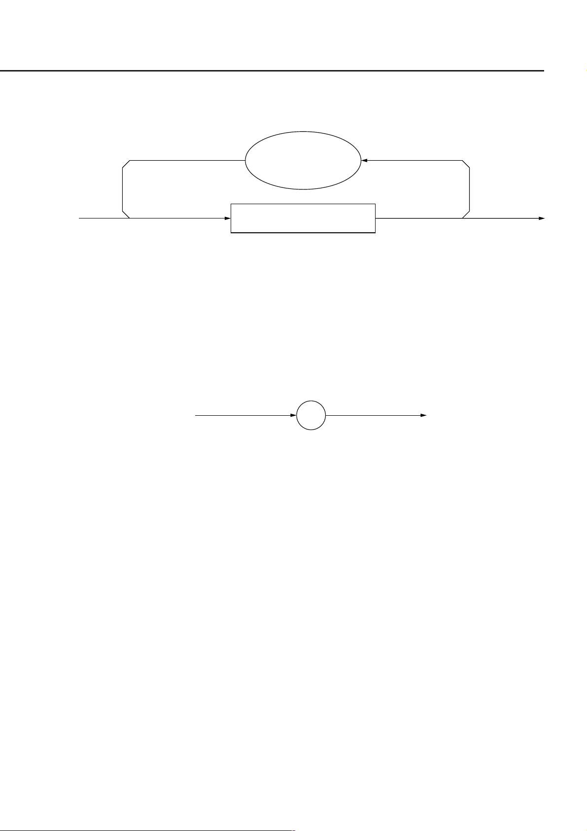
6.2 Response Message Functional Elements
6.2.3 <RESPONSE MESSAGE>
<RESPONSE MESSAGE> is defined as follows:
<RESPONSE
MESSAGE UNIT
SEPARATOR>
Refer to 6.2.4
<RESPONSE MESSAGE UNIT>
Refer to 6.2.5
<RESPONSE MESSAGE> is a sequence of one or more <RESPONSE MESSAGE UNIT> elements.
The <RESPONSE MESSAGE UNIT> element is a single message sent from a device to a controller. A <RESPONSE
MESSAGE UNIT SEPARATOR> is used as a separator for separating multiple <RESPONSE MESSAGE UNIT>
elements.
6.2.4 <RESPONSE MESSAGE UNIT SEPARATOR>
<RESPONSE MESSAGE UNIT SEPARATOR> is defined as follows:
;
<RESPONSE MESSAGE UNIT SEPARATOR> is used to separate <RESPONSE MESSAGE UNIT> elements with
a <UNIT SEPARATOR>, or a semi-colon (;), when outputting a sequence of multiple <RESPONSE MESSAGE
UNIT> elements as one <RESPONSE MESSAGE>.
6-5

Section 6 Talker Output Format
6.2.5 <RESPONSE MESSAGE UNIT>
<RESPONSE MESSAGE UNIT> is defined as follows:
<RESPONSE
DATA SEPARATOR>
Refer to 6.2.7
<RESPONSE
HEADER>
Refer to 6.2.8
<RESPONSE
HEADER SEPARATOR>
Refer to 6.2.6
<RESPONSE
DATA SEPARATOR>
Refer to 6.2.7
<RESPONSE DATA>
Refer to 6.2.9
<RESPONSE DATA>
Refer to 6.2.9
There are two kinds of useage for <RESPONSE MESSAGE UNIT>. One is <RESPONSE MESSAGE UNIT> with
header, which returns the result of processing the program-message-set information accurately. The other is <RE-
SPONSE MESSAGE UNIT> without header, which returns only the measurement result.
6.2.6 <RESPONSE HEADER SEPARATOR>
<RESPONSE HEADER SEPARATOR> is defined as follows:
SP
<RESPONSE HEADER SEPARATOR> is one space written after <RESPONSE HEADER> to be separated from
<RESPONSE DATA>.
The space SP corresponds to ASCII code byte 20 (decimal 32).
In a <RESPONSE MESSAGE> with header, a space must always exist between the header and the data as a <RE-
SPONSE HEADER SEPARATOR>. The separator indicates the end of the <RESPONSE HEADER> as well as the
beginning of <RESPONSE DATA> at the same time.
6-6

6.2 Response Message Functional Elements
6.2.7 <RESPONSE DATA SEPARATOR>
<RESPONSE DATA SEPARATOR> is defined as follows:
,
When multiple <RESPONSE DATA> elements are output, <RESPONSE DATA SEPARATOR> must be placed be-
tween thses data elements.
6.2.8 <RESPONSE HEADER>
The format of <RESPONSE HEADER> is the same as that of <COMMAND PROGRAM HEADER> described in the
Section 5.2.8 "<COMMAND PROGRAM HEADER>" with the exception of the following three points:
(1) Characters that can be used in <response mnemonic> are specified. For alphanumeric characters, only uppercase
characters must be used. Other points are the same as those of <program mnemonic>.
(2) A space cannot be written before a <RESPONSE HEADER>, while it can be written before a <PROGRAM
HEADER>.
(3) Only one space can be written before a <RESPONSE HEADER>, while two or more spaces can be written before
a <PROGRAM HEADER>.
Refer to the Table 6-2 for the response header up to <response mnemonic>.
It should be noted that only uppercase characters must be used in <response mnemonic>. Other points are the same as
those of <program mnemonic> described in the Section 5.2.8 "<COMMAND PROGRAM HEADER>."
6-7

Section 6 Talker Output Format
Table 6-2
Item Function
RESPONSE HEADER A header indicates a function of <RESPONSE DATA>. It explains the function
with a 12-character-long character-long character string or a <response mnemo-
nic> element that consists of uppercase characters, numeric characters, and/or
underline.
<simple response header>
Refer to (1)
<compound response header>
Refer to (2)
<common response header>
Refer to (3)
(1) <simple response header> is defined as follows.
<response mnemonic>
Refer to (4)
(2) <compound response header> is defined as follows.
<response
: :
mnemonic>
Refer to (4)
(3) <common response header> is defined as follows.
∗
<response mnemonic>
Refer to (4)
(4) <response mnemonic> is defined as follows.
<upper-case
†1
alpha>
<upper-case
†1
alpha>
_
<response
mnemonic>
Refer to (4)
6-8
<digit>
Refer to (4) of 5.2.8
NOTE †1:
<upper-case alpha> ASCII code bytes 41 to 5A
(decimal values 65 to 90 = uppercase characters A to Z)

6.2 Response Message Functional Elements
6.2.9 <RESPONSE DATA>
There are 11 types of <RESPONSE DATA> elements. Among these, the MT9810A transfers the <RESPONSE
DATA> shown in the hollow squares surrounded by a shade. The <RESPONSE DATA> to be returned depends on the
query message.
<CHARACTER
RESPONSE DATA>
<NR1 NUMERIC
RESPONSE DATA>
<NR2 NUMERIC
RESPONSE DATA>
<NR3 NUMERIC
RESPONSE DATA>
<HEXADECIMAL
NUMERIC RESPONSE DATA>
<OCTAL NUMERIC
RESPONSE DATA>
Refer to (1) of 6.2.9
Refer to (2) of 6.2.9
Refer to (3) of 6.2.9
Refer to (4) of 6.2.9
Refer to (5) of 6.2.9
Refer to (6) of 6.2.9
NOTE†1:
<INDEFINITE LENGTH ARBITRARY BLOCK RESPONSE DATA> and <ARBITRARY ASCII RESPONSE DATA> is terminated with NL∧END after the last byte has been transferred.
<BINARY NUMERIC
RESPONSE DATA>
<STRING
RESPONSE DATA>
<DEFINITE LENGTH
ARBITRARY BLOCK RESPONSE DATA>
<INDEFINITE LENGTH
ARBITRARY BLOCK RESPONSE DATA>
<ARBITRARY ASCII
RESPONSE DATA>
†1
Refer to (7) of 6.2.9
Refer to (8) of 6.2.9
Refer to (9) of 6.2.9
†1
Refer to (10) of 6.2.9
Refer to (11) of 6.2.9
6-9

Section 6 Talker Output Format
Item Function
(1) CHARACTER
RESPONSE DATA
Data consisting of the same character string as that of <response mnemonic>.
Accordingly, the character string always begins with an uppercase character and
its length is less than 12 characters. Numeric parameters must not be used.
Table 6-3
<response mnemonic>
Refer to (4) of 6.2.8
(2) NR1 NUMERIC
RESPONSE DATA
<Example>
123
+123
–1234
(3) NR2 NUMERIC
RESPONSE DATA
<Example>
12.3
+12.34
–12.345
Integer data, i.e., a decimal value of an integer that has neither decimal point nor
exponent.
+
<digit>
Refer to (4) of 5.2.8
–
Fixed-point data, i.e., a decimal value other than integers or a decimal value hav-
ing an exponent.
+
<digit>
Refer to (4)
of 5.2.8
.
<digit>
Refer to (4)
of 5.2.8
–
(4) NR3 NUMERIC
RESPONSE DATA
<Example>
1.23E+4
+12.34E–5
–12.345E+6
• Lowercase
characters cannot be
used for E.
• E must not be
preceded and
followed by a space.
• + in the exponent part
is mandatory.
• + in the mantissa part
is mandatory.
6-10
Fixed-point data, i.e., a decimal value having an exponent.
+
<digit>
Refer to (4)
of 5.2.8
.
–
+
E
–
<digit>
Refer to (4)
of 5.2.8
<digit>
Refer to (4)
of 5.2.8

Item Function
(5) HEXADECIMAL
NUMERIC RESPONSE
DATA
6.2 Response Message Functional Elements
Table 6-3 (continue)
Data represented in hexadecimal notation.
A
<Example>
#HABC123
#H2DC3
#H8301
(6) OCTAL NUMERIC
RESPONSE DATA
<Example>
#Q37
#Q26703
#Q30562
#
Data represented in octal notation.
B
H C
D
E
F
<digit>
0
1
2
(7) BINARY NUMERIC
RESPONSE DATA
<Example>
#B011101
#B1011
#B1011
#
Q
Data represented in binary notation.
#
B
3
4
5
6
7
0
1
6-11

Section 6 Talker Output Format
Item Function
(8) STRING RESPONSE
DATA
Any ASCII 7-bit code can be used.
The character string must be enclosed with double quotation marks (").
When a character string contains double quotation marks, two identical quotation
<Example>
"This is a text"
"Say,""Hello""."
marks must be written in succession per quotation mark.
Since a CR, LF, of space can be used, this element is suitable for outputting a text
to the printer or CRT.
Table 6-3 (continue)
(9) DEFINITE LENGTH
ARBITRARY BLOCK
RESPONSE DATA
<Example>
Transferring 11256099D
in a 4-byte blocks
↓
#1400ABC123
(10) INDEFINITE LENGTH
ARBITRARY BLOCK
RESPONSE DATA
"
"
<inserted">
"
<non-double
quote char>
Fixed-point 8-bit binary block data.
It is suitable for transferring large-volume data, 8-bit extended ASCII code, and
non-display data. Refer to the Section 5.3.6 "<ARBITRARY BLOCK PRO-
GRAM DATA>" for more details on individual elements.
<non-zero
#
digit>
Referto
5.3.6
<digit>
Referto
5.3.6
<8-bit
data byte>
Referto5.3.6
Indefinite-length 8-bit binary block data.
#0 must be written before the first data.
The last data must be followed by NL∧END for termination.
<Example>
Indefinite-length
–250, –50, 120, ...
are transferred
↓
#0FF06FFCE0078
(11) ARBITRARY ASCII
RESPONSE DATA
<Example 1>
<ASCII Byte><ASCII
Byte>NL∧END
<Example 2>
NL∧END
6-12.
<8-bit
#
0 ∧ END
data byte>
Referto5.3.6
NL
ASCII data bytes except NL character transferred in succession.
The last data must be followed by NL∧END for termination.
<ASCII data byte>
NL
∧ END

Section 7 Common Commands
This section explains common commands and common query commands specified by IEEE 488.2. These common
commands are not bus commands which are used as interface messages. Like device messages, the common com-
mands are data messages used when the bus data mode (or the ATN line) is False. These commands can be applied to
all measuring instruments, including those of other companies, that comply with IEEE 488.2. IEEE 488.2 common
commands always begin with an asterisk (∗).
7.1 Classification of Supported Commands and References .. 7-2
7-1

Section 7 Common Commands
7.1 Classification of Supported Commands and Refer-
ences
MT9810A-supported commands discussed previously are classified by function group as shown in the Table 7-1.
Details on these commands are given in alphabetical order on the next and subsequent pages.
Table 7-1
Group Function by group Mnemonic
System data
Internal operation
Synchronization
Status and event
Information about device connected to the system (e.g., manufacturer
name, type name, and serial number) is returned.
Control inside the device:
(a) Resetting of device at level 3
(b) Self-test and error detection inside the device
A device is synchronized with the controller by:
(a) Service request wait
(b) Device output queue wait
(c) Forced sequential execution
A status byte consists of a status summary message. Summary bits of
the status summary message are set by a standard event register,
output queue, and extended event register (or an extended queue).
Three commands and four queries are provided to set, clear, validate,
and invalidate the data in these registers and queues and to know the
register settings using queries.
∗IDN?
∗OPT?
∗RST
∗TST?
∗OPC
∗OPC?
∗WA I
∗CLS
∗ESE
∗ESE?
∗ESR?
∗SRE
∗SRE?
∗STB?
7-2

∗CLS Clear Status Command
(Clears status byte registers)
(1) Format
∗CLS
(2) Explanation
The ∗CLS common command clears all status structures (i.e., event registers and queues) except an output queue
and its MAV summary messages, thus clearing the corresponding summary messages.
Issuing a ∗CLS command after <PROGRAM MESSAGE TERMINATOR> or before <QUERY MESSAGE
UNIT> will clear all status bytes. With this method, all unread messages in the output queue will also be cleared.
Values set in enable registers are not changed by the ∗CLS command.
Service request
occurrence
7
Extended event
register or queue
Standard event
register
∗CLS
Command
(Not used)
MSS 6 RQS
ESB
MAV
3
2
1
0
Status Byte Register
Status summary
message
Data
Data
Data
Data
Extended event
register or queue
Extended event
register or queue
Extended event
register or queue
Extended event
register or queue
Data
……Output Queue
(Queue is not used)
(Queue is not used)
(Not used)
(Not used)
7-3
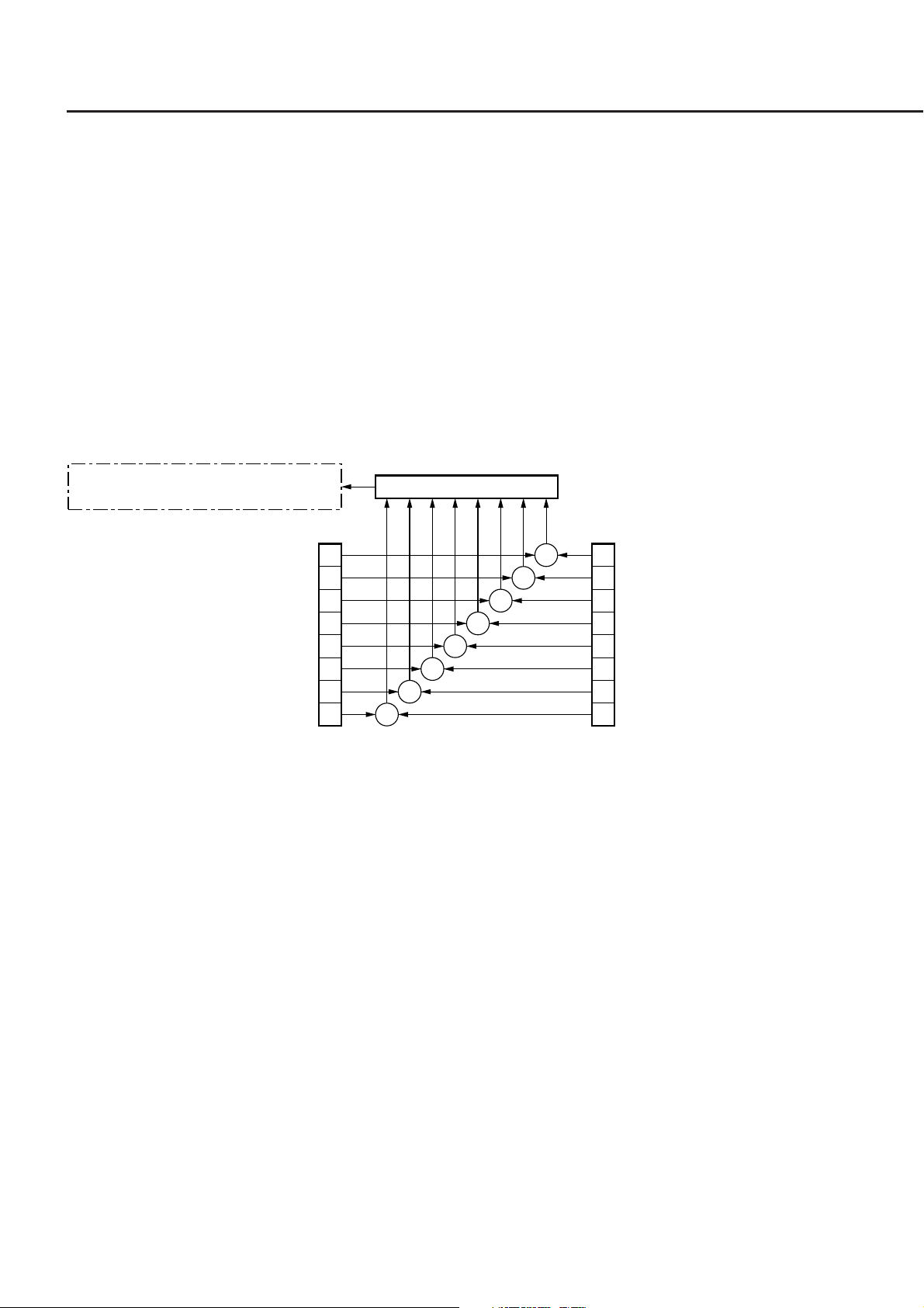
∗ESE
Section 7 Common Commands
Command/Query
∗ESE Standard Event Status Enable Command
(Sets or clears the standard event status enable register)
(1) Format
∗ESE<HEADER SEPARATOR><DECIMAL NUMERIC PROGRAM DATA>
In this particular format <DECIMAL NUMERIC PROGRAM DATA> is a value rounded to an integer, 0 to 255
(base is 2 and binary weights are assigned).
(2) Explanation
0
The total of values (2
standard event status enable register bits 1, 2, 3, 4, 5, 6, and/or 7 that are to be enabled becomes program data.
The value of the bit to be disabled is 0.
= 1, 21 = 2, 22 = 4, 23 = 8, 24 = 16, 25 = 32, 26 = 64, and/or 27 = 128) corresponding to the
To be set in Status Byte Register bit
5, an ESB (Event Summary Bit)
disabled=0, enabled=128 (27)
disabled=0, enabled=64 (2
disabled=0, enabled=32 (2
disabled=0, enabled=16 (2
disabled=0, enabled=8 (2
disabled=0, enabled=4 (2
disabled=0, enabled=2 (2
disabled=0, enabled=1 (2
6
)
5
)
4
)
3
)
2
)
1
)
0
)
Standard Event Status
Enable Register
7
6
5
4
3
2
1
0
&
Logical OR
&
&
&
&
&
&
&
Power-ON
7
User request
6
Command error
5
Execution error
4
Device-dependent error
3
Query error
2
Bus control request
1
Operation complete
0
Standard Event Status
Register
∗ESE? Standard Event Status Enable Quer
(Returns the current value of the standard event status enable register)
(1) Format
∗ESE?
(2) Explanation
The value (NR1) of the standard event status enable register is returned.
(3) Response message
NR1 = 0 to 255
7-4
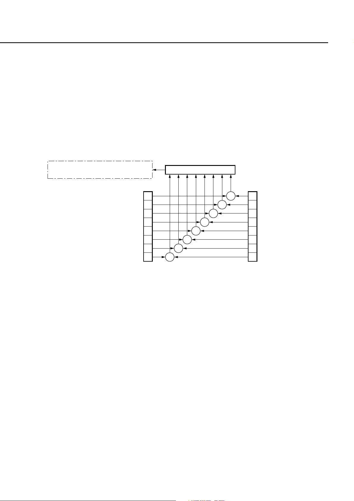
∗ESR?
∗ESR? Standard Event Status Register Query
(Returns the current value of the standard event status register)
(1) Format
∗ESR?
(2) Explanation
0
The current value NR1 of the standard event status register is returned. The total of values (2
3
= 8, 24 = 16, 25 = 32, 26 = 64, and/or 27 = 128) corresponding to the standard event status enable register bits 1,
2
2, 3, 4, 5, 6, and/or 7 that are enabled becomes NR1. When the response is read (e.g., line 40), this register is
cleared.
= 1, 21 = 2, 22 = 4,
Query
To be set in Status Byte Register bit
5, an ESB (Event Summary Bit)
disabled=0, enabled=128 (27)
disabled=0, enabled=64 (2
disabled=0, enabled=32 (2
disabled=0, enabled=16 (2
disabled=0, enabled=8 (2
disabled=0, enabled=4 (2
disabled=0, enabled=2 (2
disabled=0, enabled=1 (2
Standard Event Status
Enable Register
(3) Response message NR1
NR1 = 0 to 255
Logical OR
7
6
6
)
5
5
)
4
4
)
3
3
)
2
2
)
1
1
)
0
0
)
&
&
&
&
&
&
&
&
Power-ON
7
User request
6
Command error
5
Execution error
4
Device-dependent error
3
Query error
2
Bus control request
1
Operation complete
0
Standard Event Status
Register
7-5
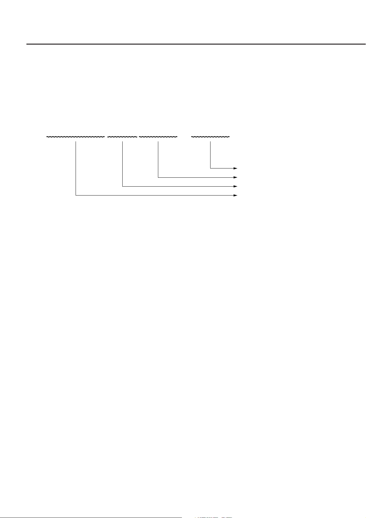
∗IDN?
Section 7 Common Commands
Query
∗IDN? Identification Query
(Returns the manufacturer name, type name, serial number, and firmware level of the product)
(1) Format
∗IDN?
(2) Explanation
A manufacturer name, type name, serial number, and firmware level are returned.
Software version
0
MT9810A
ANRITSU
When the manufacturer of the product, whose type name, serial number, and software/hardware version number
are Anritsu, 0, and 1 respectively. Sending a common query ∗IDN? to a device will return a response message
consist of the above four fields.
Field 1 .......... Product manufacturer (e.g., ANRITSU)
Field 2 .......... Type name
Field 3 .......... Serial number (e.g., 0)
Field 4 .......... Firmware version No. (control software version and optical software version)
Return ASCII character "0" to not to return a serial number and firmware version in fields 3 and 4.
(3) Response message
A response message which consists of the above four fields separated by commas is sent as <ARBITRARY
ASCII RESPONSE DATA>.
<Field 1>,<Field 2>,<Field 3>,<Field 4>
Overall length of the response message is less than 72 characters.
7-6
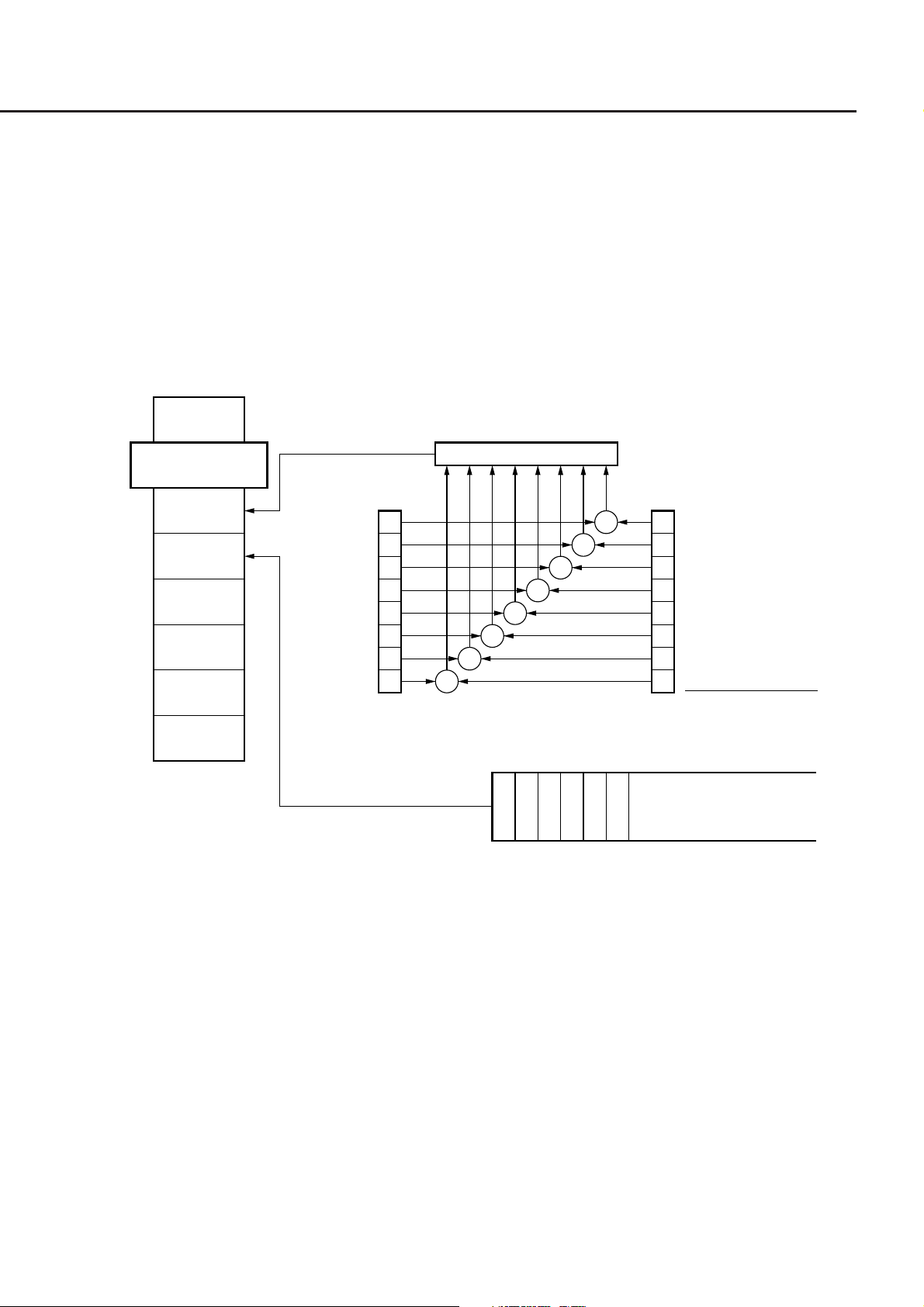
Command/Query
∗OPC Operation Complete Command
(Sets bit 0 of the standard event status register when device operations have been completed)
(1) Format
∗OPC
(2) Explanation
When all the pending device operations have been completed, standard event status register bit 0 (i.e., operation
complete bit) is set. However, since the MT9810A does not have an overlap command, the ∗OPC command
counts for nothing.
7
∗OPC
MSS 6 RQS
ESB
MAV
3
2
1
0
Status Byte Register
7
6
5
4
3
2
1
0
enabled=2
Standard Event Status
Enable Register
0
Logical OR
&
&
&
&
&
&
&
&
Standard Event Status
Register
1
……Output Queue
Power-ON
7
User request
6
Command error
5
Execution error
4
Device-dependent error
3
Query error
2
Bus control request
1
Operation complete
0
∗OPC? Operation Complete Query
(When device operations have been completed, sets "1" in the output queue to generate an MAV
summary message)
(1) Format
∗OPC?
(2) Explanation
When all the pending device operations have been completed, "1" is set in the output queue, waiting for an MAV
summary message to occur.
(3) Response message
"1" is returned as <NR1 NUMERIC RESPONSE DATA>.
7-7

∗RST
Section 7 Common Commands
Command
∗RST Reset Command
(Rests a device at level 3)
(1) Format
∗RST
(2) Explanation
The ∗RST (Reset) command resets a device at level 3 (Refer to the Table 4-1). At level 3, the following items
are initialized:
(a) Device-dependent functions and states are restored to known states irrespective of the device history.
(b) The macro defined by ∗DDT command is restored to the device-defined state.
(c) A mode in which macro operation is disabled and macros are not accepted, is set. Macro definitions are
restored to the designer-specified states.
(d) The specified device is set in the OCIS. The operation complete bit cannot be set in the standard event status
register.
Section 8.1
(e) The specified device is set in the OQIS. The operation complete bit cannot be set in the output queue. The
MAV bit is cleared.
The ∗RST command does not affect the following:
(a) IEEE 488.1 interface state
(b) Device address
(c) Output queue
(d) Service request enable register
(e) Standard event status enable register
(f) Power-on-status-clear flag setting
(g) Calibration data affecting device standard
(h) RS-232C interface condition
7-8

∗OPT?
∗OPT? Option Identification Query
(Reports an installed option list)
(1) Format
∗OPT?
(2) Explanation
States of installed options are returned using 1 or 0.
(3) Response message
A response message which consists of the above three fields separated by commas is sent as <ARBITRARY
ASCII RESPONSE DATA>.
Since there is no option now "0" is returned.
Query
7-9

∗SRE
Section 7 Common Commands
Command/Query
∗SRE Service Request Enable Command
(Sets a service request enable register bit)
(1) Format
∗SRE<HEADER SEPARATOR><DECIMAL NUMERIC PROGRAM DATA>
In this particular format <DECIMAL NUMERIC PROGRAM DATA> is a value rounded to an integer, 0 to 255
(base is 2 and binary weights are assigned).
(2) Explanation
0
The total of values (2
request enable register bits 1, 2, 3, 4, 5, 6, and/or 7 that are enabled becomes NR1. The value of the bit to be
disabled is 0.
= 1, 21 = 2, 22 = 4, 23 = 8, 24 = 16, 25 = 32, and/or 27 = 128) corresponding to the service
Service Request
Generation
Logical OR
disabled=0, enabled=128 (27)
7
&
Not used
disabled=0, enabled=32 (2
disabled=0, enabled=16 (2
disabled=0, enabled=8 (2
disabled=0, enabled=4 (2
disabled=0, enabled=2 (2
disabled=0, enabled=1 (2
5
)
5
4
4
)
3
3
)
2
2
)
1
1
)
0
0
)
&
&
&
&
&
&
Status Byte RegisterService Request Enable Register
∗SRE? Service Request Enable Query
(Returns the current value of the service request enable register)
(1) Format
∗SRE?
(2) Explanation
The value NR1 of the service request enable register is returned.
Not used
7
MSS 6 RQS
ESB
5
MAV
4
ESB (ERROR)
3
ESB (END)
2
Not used
1
Not used
0
Status summary message
(3) Response message NR1
Since NR1 = bit 6 (RQS bit) cannot be set, NR1 = 0 to 63 or 128 to 191.
7-10

∗STB?
∗STB? Read Status Byte Command
(Returns the current value of the status byte including the MSS bit)
(1) Format
∗STB?
(2) Explanation
The ∗STB? command returns the total of the status register value assigned binary weights and MSS (master
Summary Status) summary message value as <NR1 NUMERIC RESPONSE DATA>.
(3) Response message
A response message (<NR1 NUMERIC RESPONSE DATA>) is an integer ranging from 0 to 255. It is the total
of status byte register bit values. Status byte register bits 0 to 5 and 7 is assigned weights 1, 2, 4, 8, 16, 32, and
128 respectively, and the MSS bit is assigned weight 64. The MSS indicates that there is at least one reason for
requesting a service. The status byte register conditions of MT9810A are summarized in the Table 7-2.
Query
disabled=0, enabled=128 (27)
Not used
disabled=0, enabled=32 (2
disabled=0, enabled=16 (2
disabled=0, enabled=8 (2
disabled=0, enabled=4 (2
disabled=0, enabled=2 (2
disabled=0, enabled=1 (2
Bit
7
6
5
4
3
2
1
0
Bit weights
128
64
32
16
8
4
2
1
Bit name
MSS
ESB
MAV
ESB (ERROR)
ESB (END)
Service Request
Generation
Logical OR
Status summary message
7
&
7
Not used
MSS 6 RQS
5
)
5
4
4
)
3
3
)
2
2
)
1
1
)
0
0
)
&
&
&
&
&
&
ESB
5
MAV
4
ESB (ERROR)
3
ESB (END)
2
Not used
1
Not used
0
Status Byte RegisterService Request Enable Register
Table 7-2
Status byte register conditions
0 = Not used.
0 = No service is not requested. 1 = A service is requested.
0 = No event service has occurred. 1 = An event status has occurred.
0 = Data does not exist in the output queue.
1 = Data exists in the output queue.
0 = No event status has occurred. 1 = An event status has occurred.
0 = No event status has occurred. 1 = An event status has occurred.
0 = Not used.
0 = Not used.
7-11

∗TST?
Section 7 Common Commands
Query
∗TST? Self-Test Query
(Conducts an internal self-test and indicates whether any error has occurred)
(1) Format
∗TST?
(2) Explanation
The ∗TST? command conducts a self-test inside the device. The test result is set in the output queue. The data in
the output queue indicates that the test has been completed without causing any error. The self-test does not
require operator intervention.
(3) Response message
A response message is sent as <NR1 NUMBER RESPONSE DATA>.
Data range = –32767 to 32767
NR1 = – ........ The test has been completed without causing any error.
NR1 = 1 ........ The test has not been conducted or any error occurred during the test.
7-12

∗WAI Wait-to-Continue Command
(Causes the next command to wait until the current command has been executed by the device)
(1) Format
∗WAI
(2) Explanation
The ∗WAI command executes overlap commands as sequential commands.
If the device can start executing the next command while processing a command or query from the controller, the
command or query is called an overlap command.
If a ∗WAI command is executed after an overlap command, the next command must wait for the ∗WAI common
command to end. This also applies to sequential commands.
However, since the MT9810A does not support overlap commands. The ∗WAI command counts for nothing.
∗WAI
Command
7-13

Section 7 Common Commands
7-14.

Section 8 Status Structure
This section explains the device status data specified by IEEE 488.2, the status data structure, and the technique of
synchronization between a device and a controller.
8.1 IEEE 488.2 Standard Status Model ................................... 8-3
8.2 Status Byte Register........................................................... 8-5
8.2.1 ESB and MAV Summary Message ...................... 8-5
8.2.2 Device Dependent Summary Message ............... 8-6
8.2.3 Reading and Clearing the Status Byte Register ..... 8-7
8.3 Enabling the SRQ ............................................................... 8-9
8.4 Standard Event Status Register ......................................... 8-10
8.4.1 Definition of Standard Event Status Register Bits ... 8-10
8.4.2 Details on Query Errors ........................................ 8-11
8.4.3 Reading, Writing, and Clearing the Standard
Event Status Register ........................................... 8-12
8.4.4 Reading, Writing, and Clearing the Standard
Event Status Enable Register .............................. 8-12
8.5 Queue Model ...................................................................... 8-13
8.6 Extended Status Bytes ....................................................... 8-15
8.6.1 Status register ...................................................... 8-16
8.6.2 Operation Status Register .................................... 8-19
8.6.3 QUESTIONABLE Status Register ........................ 8-22
8-1

Section 8 Status Structure
The status byte (STB) sent to the controller is specified by IEEE 488.1. The bits of the status byte represent a status
summary message, providing a summary of the current contents of the data stored in a register or queue.
The following sections explain the status summary message bits, the status data structure for generating these status
summary message bits, and the technique of synchronizing a device with the controller using the status messages.
These functions are used to control devices from an external controller via the GPIB interface. These functions, except
a few, can also be used to control devices from an external controller via the RS-232C interface.
8-2
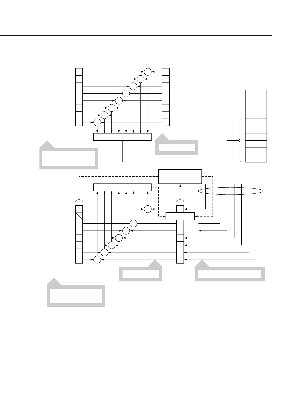
8.1 IEEE 488.2 Standard Status Model
8.1 IEEE 488.2 Standard Status Model
The diagram shown below is the standard model of the status data structure specified by IEEE 488.2.
Enable Register
Set with ∗ESE <NRf>
Read with ∗ESE?
Service Request
Enable Register
7
6
5
4
3
2
1
0
7
5
4
3
2
1
0
&
&
&
&
&
&
&
Logical OR
Logical OR
&
&
&
Read by ∗STB?
&
&
&
&
&
7
Power-ON (PON)
6
User request (URQ)
5
Command error (CME)
4
Execution error (EXE)
3
Device-dependent error (DDE)
2
Query error (QYE)
1
Bus control request (RQC)
0
Operation complete (OPC)
Standard Event Status RegisterStandard Event Status
Read by ∗ESR?
Service Request
Generation
7
MSS 6 RQS
5
4
3
2
1
0
Status Byte
Register
⋅
⋅
⋅
⋅
Data
Data
Data
Data
Data
Data
Output Queue
Status summary message
ESB
MAV
Read in the serial poll mode.
Set with ∗SRE <NRf>.
Read with ∗SRE?.
Fig. 8-1 Standard status model
8-3

Section 8 Status Structure
The status model uses an IEEE 488.1 status byte. This status byte consists of seven summary message bits provided by
the status data structure. To generate these summary message bits, the status data structure is comprised of two
models: a register model and a queue model.
Register model
A pair of registers used to record an event that a device has encountered and a condition. It consists of an event status
register and an event status enable register. When the results of ANDing the values of bits of these registers is not 0,
the corresponding status register bits are set to 1s. In other cases, the corresponding status register bits are set to 0s. If
the result of ORing the values of status register bits is 1, the summary message bit is set to 1. If the result of ORing
these bits is 0, the summary message bit is set to 0.
Queue model
A data structure in which status values or information are removed in the same order of which those were entered.
Only when the queue structure contains data, the corresponding bit is set to 1. If it is empty, the corresponding bit is set
to 0.
Based on the concept of the above register model and queue model, the IEEE 488.2 standard status model is con-
structed from two types of register models and a queue model.
(1) Standard event status register and standard event status enable register
This register has the register model structure mentioned above. It has eight bits corresponding to eight standard
events listed below encountered by the device.
(a) power on
(b) user request
(c) command error
(d) execution error
(e) device dependent error
(f) query error
(g) bus control request
(h) operation complete.
The result of logical OR is output to the status byte register bit 5 (DIO 4) as an event status bit (ESB) summary
message.
(2) Status byte (STB) register and service request enable (SRE) register
The status byte register consists of an RQS bit and seven summary message bits for setting status summary
messages from the status data structure. It is used in combination with a service request enable register. When
the result of ORing the values of these two registers is 0, the SRQ is set ON. In this case, the status byte register
bit "DIO 7" is reserved by the system as an RSQ bit, so this bit indicates to an external controller that a service
request exists. The function of the SRQ conforms to IEEE 488.1.
(3) Output queue
This queue has the queue model structure mentioned above. Its contents are summarized and transferred to the
status byte register bit 4 (DIO 5) as a MAV (message available) summary message.
8-4

8.2 Status Byte Register
8.2 Status Byte Register
The status byte register consists of device STB and RQS (or MSS) messages. IEEE 488.1 defines the method of
reporting STB and RQS messages, but it does not define the setting and clearing protocols and STB meaning. IEEE
488.2 defines device status summary messages and MSS transferred to bit 6 along with an STB in response to the
∗STB? common query.
8.2.1 ESB and MAV Summary Message
The followings are the explanations of an ESB summary message and an MAV summary message.
(1) ESB summary message
The ESB (event summary bit) summary message is defined by IEEE 488.2. It appears in status byte register bit
5. This bit indicates whether one or more IEEE 488.2 defined events have occurred, with the service request
enable register set to allow events to occur, after the standard event status register was read or cleared last. The
ESB summary message bit becomes True when at least one event registered in the standard event status register
becomes True with event occurrence enabled. Conversely, the ESB summary bit becomes False when none of
the registered events has occurred even if event occurrence is enabled.
(2) MAV summary message
The MAV (message available) summary message is defined by IEEE 488.2. It appears in status byte register bit
4. This bit indicates whether the output queue is empty. When a device is ready for accepting response messages
from the controller, the MAV summary message bit becomes 1 (True). When the output queue is empty, this bit
becomes 0 (False). This message is used to synchronize information exchange with the controller. For example,
the controller can send a query message to the device and wait for the MAV to become True. The controller can
perform another processing while waiting for a response from the device. If the controller has started reading the
output queue without checking the MAV, all system bus operations are suspended until a response is received
from the device.
8-5

Section 8 Status Structure
8.2.2 Device Dependent Summary Message
IEEE 488.2 does not define whether status register bit 7 (DIO 8) and bit 3 (DIO 4) to bit 0 (DIO 1) are used as status
register summary bits or the bits indicating existence of data in the queue. Accordingly, these bits can be used as
device dependent summary message bits.
Device dependent summary messages have a register model or queue model status data structure. This status register
is a pair of registers used to report events and states in parallel or a queue used to report states and information
sequentially. The summary bit provides a summary of the current status of the corresponding status data structure. For
the register model, the summary message bit becomes True when one or more events have become True with occur-
rence of events enabled. For the queue model, the summary message bit becomes True when the queue is not empty.
In the MT9810A, bit 1 and bit 0 are unused, and bits 3 and 7 are used as summary bits of the status register; bit 2 is
allocated to the queue as shown in the following diagram. Therefore, there are four types (two types for extension) of
register models and there are two types (one type for extension) of queue models.
Service request
occurrence
7
Extended event
register or queue
Standard event
register
(Not used)
MSS 6 RQS
ESB
MAV
3
2
1
0
Status Byte Register
Status summary
message
Data
Data
Data
Data
Extended event
register or queue
Extended event
register or queue
Extended event
register or queue
Extended event
register or queue
Data
……Output Queue
(Queue is not used)
(Queue is not used)
(Not used)
(Not used)
8-6
 Loading...