


 Loading...
Illustra Pro Series
Installation and Configuration Guide
Notice
Pleasereadthis manual thoroughly andsaveit forfutureusebeforeattemptingtoconnect oroperate this unit.
Theinformationinthis manual was current whenpublished. Themanufacturerreserves theright to reviseandimproveits products. All specifications arethereforesubject tochangewithout notice.
Copyright
Undercopyright laws, thecontents of this manual may not becopied, photocopied, reproduced, translatedorreducedtoany electronic medium ormachine-readableform, inwholeorinpart, without priorwrittenconsent of TycoSecurity Products.
© 2018TycoSecurity Products. All rights reserved.
TycoSecurity Products
6600Congress Avenue
BocaRaton, FL33487U.S.A.
Customer Service
Thank youforusingAmericanDynamics products. Wesupport ourproducts throughanextensive worldwidenetwork of dealers. Thedealerthroughwhom youoriginally purchasedthis product is your point of contact if youneedserviceorsupport. Ourdealers areempoweredtoprovidethevery best in customerserviceandsupport. Dealers shouldcontact AmericanDynamics at (800)507-6268or (561)912-6259oronthewebat www.americandynamics.net.
Trademarks
Thetrademarks, logos, andservicemarks displayedonthis document areregisteredintheUnited States [orothercountries]. Any misuseof thetrademarks is strictly prohibitedandTycoSecurity Products will aggressively enforceits intellectual property rights tothefullest extent of thelaw, includingpursuit of criminal prosecutionwherevernecessary. All trademarks not ownedby Tyco Security Products aretheproperty of theirrespectiveowners, andareusedwithpermissionor allowedunderapplicablelaws.
Product offerings andspecifications aresubject tochangewithout notice. Actual products may vary from photos. Not all products includeall features. Availability varies by region; contact yoursales representative.

Table of Contents
Overview |
6 |
Illustra Pro 2MP and 3MP Compact Cameras |
7 |
Product features |
7 |
Product overview |
7 |
Installation |
10 |
System requirements |
16 |
Network Topology |
17 |
Network Connection |
18 |
DefaultIPAddress |
18 |
DHCP |
19 |
ManagingcameraswiththeIllustraConnecttool |
20 |
Configuration |
23 |
Live menu |
26 |
Quick Start Menu |
28 |
BasicConfiguration |
28 |
Video Menu |
41 |
Streams |
41 |
PictureSettings |
44 |
Date/Time/OSD |
49 |
PrivacyZones |
52 |
Events and Actions Menu |
54 |
EventSettings |
54 |
EventActions |
57 |
Analytics |
59 |
EventLogs |
61 |
Security |
65 |
SecurityStatus |
65 |
SecurityStatus |
67 |
Users |
68 |

IllustraProSeries InstallationandConfigurationGuide
HTTP/HTTPS |
70 |
IEEE802.1x |
71 |
Firewall |
72 |
RemoteAccess |
74 |
SessionTimeout |
77 |
Network Menu |
78 |
TCP/IP |
78 |
Multicast |
79 |
FTP |
80 |
SMTP |
82 |
SNMP |
83 |
CIFS |
84 |
DynamicDNS |
84 |
System |
86 |
Maintenance |
86 |
Date/Time |
90 |
HealthMonitor |
91 |
Logs |
91 |
About |
93 |
Edge Recording |
94 |
SD CardManagement |
94 |
RecordSettings |
96 |
EventDownload |
97 |
Appendix A: User Account Access |
98 |
Appendix B: Using Media Player to View RTSP Streaming |
100 |
Appendix C: Stream Resolutions |
101 |
Appendix D: Camera Defaults |
103 |
End User License Agreement (EULA) |
111 |
8200-1631-03C0 |
4 |

IllustraProSeries InstallationandConfigurationGuide
Warning
•ThisunitoperatesatPoE+.
•Installationandserviceshouldbeperformedonlybyqualifiedandexperiencedtechniciansandcomplywithall localcodesandrulestomaintainyour warranty.
•Toavoiddamagetotheunit,never connectmorethanonetypeofpower supply(PoEIEEE802.3EthernetClass
0)atthesametime. IfusingPoE,thiscameraistobeconnectingonlytoPoEnetworkswithoutroutingto heterogeneousdevices.
•Thecameraisnotintendedtobedirectlyconnectedtoanexternalnetworkandthevideocoaxconnections shouldonlybeconnectedintra-building.
•Toreducetheriskoffireor electricshock,donotexposetheproducttorainor moisture.
•Wipethecamerawithadrysoftcloth. For toughstains,slightlyapplywithdilutedneutraldetergentandwipewith adrysoftcloth.
•Donotapplybenzeneor thinner tothecamera,whichmaycausethesurfaceoftheunittobemeltedor lenstobe fogged.
•Avoidaligningthelenstoverybrightobjects(for example,lightfixtures) for longperiodsoftime.
•ITEistobeconnectedonlytoPoEnetworkswithoutroutingtotheoutsideplant.
•Thepower supplyshallbeapprovedfor ITENEC Class2or LPS,550mAminimumand50degreesCelsius.
•VideoOutconnectionshouldbeintra-buildingonly.
•Avoidoperatingor storingtheunitinthefollowinglocations:
•Extremelyhumid,dusty,or hot/coldenvironments. Recommendedoperatingtemperatureis:
•CompactMiniDome: -40˚C to50˚C (-40˚F to122˚F)
•Power over Ethernet(PoE) doesnotsupportheater.
•Near sourcesofpowerfulradioor TVtransmitters.
•Near fluorescentlampsor objectswithreflections.
•Under unstableor flickeringlightsources.
WEEE (Waste Electrical and Electronic Equipment). Correctdisposalofthisproduct(applicableintheEuropeanUnion andother Europeancountrieswithseparatecollectionsystems). Thisproductshouldbedisposedof,at the end of its useful life, as per applicable local laws, regulations, and procedures.
5 |
8200-1631-03C0 |

IllustraProSeries InstallationandConfigurationGuide
Overview
This IllustraProInstallationandConfigurationGuideis ausermanual whichprovides physical properties, installation, andconfigurationinformationof thecameras inTable1onPage6.
|
Table 1 Product codes |
|
|
|
|
Product Code |
Description |
|
IPS02CFOCWST |
Illustra Pro 2MP Compact Dome, 2.8mm, vandal, clear, white, SDN, |
|
TWDR |
||
|
||
IPS03CFOCWST |
Illustra Pro 3MP Compact Dome, 2.8mm, vandal, clear, white, SDN, |
|
TWDR |
||
|
Thefirst portionof this guidecontains informationpertainingspecifically totheaforementioned cameras.
•FortheIllustraPro2MP and3MP Compact Mini Domecameras, refertoIllustraPro 2MP and3MP Compact Cameras onpage7.
Thesecondportionof this guidecontains informationregardingtheIllustraUserWebInterfaceand thewebconfigurationof theaforementionedcameras. RefertoConfigurationonpage23for procedural informationpertainingtocameraconfiguration.
6 |
8200-1631-03C0 |
IllustraProSeries InstallationandConfigurationGuide
Illustra Pro 2MP and 3MP Compact Cameras
This chapterprovides product features, installationprocedures, andconnectioninformationregarding theIllustraPro2MP and3MP Compact cameras.
Product features
Lens cases requirespecial carewhenhandlingandcleaningtoavoidscratches. Forinformationon bubblehandlingandcleaning, see 8200-1174-01BubbleClearingProcedureApplicationNote.
Goto https://illustracameras.com/products.
From theProducts page, select yourcameraproduct rangeandthenselect yourcameramodel. Click
Downloads andsearchfor BubbleHandlingandCleaningProcedure.
Product overview
This chapterexplains thefeatures andinstallationof thellustraPro2MP and3MP Compact cameras. Product codeanddescriptionof thecamerais providedinTable2onpage7.
Table 2 Product code and description of the Compact camera
Product Code |
Description |
IPS02CFOCWST |
Illustra Pro 2MP Compact Dome, 2.8mm, vandal, clear, white, SDN, TWDR |
|
|
IPS03CFOCWST |
Illustra Pro 3MP Compact Dome, 2.8mm, vandal, clear, white, SDN, TWDR |
|
|
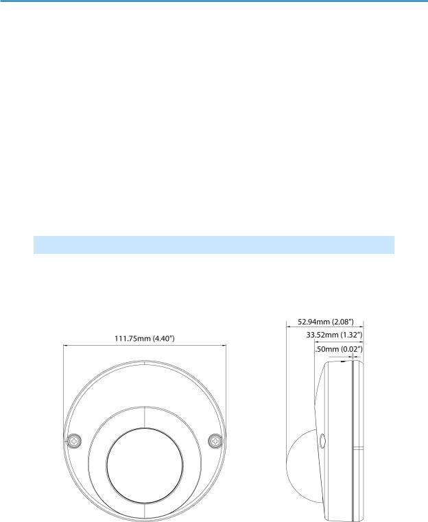
Figure 3 Physical dimensions of the Compact cameras (mm)
8200-1631-03C0 |
7 |
IllustraProSeries InstallationandConfigurationGuide
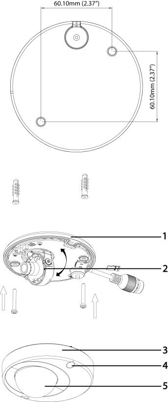
Figure 4 Physical dimensions of the Compact cameras (mm)
Figure 5 Pictorial index of the Compact cameras
8 |
8200-1631-03C0 |
IllustraProSeries InstallationandConfigurationGuide
Table 6 Pictorial index descriptions
Index number |
Description |
|
1 |
Camera base |
|
|
|
|
2 |
Lens Unit |
|
|
|
|
3 |
Camera top case |
|
|
|
|
4 |
Screw casing (Loosen the screws to take off |
|
the top cover) |
||
|
||
5 |
Dome cover |
|
|
|
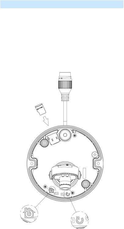
Figure 7 Interior view and buttons of the unit
8200-1631-03C0 |
9 |
IllustraProSeries InstallationandConfigurationGuide
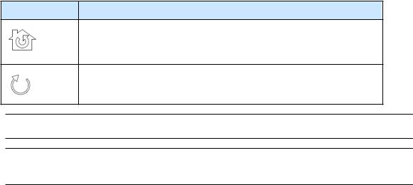
Table 8 Interior button descriptions
Interior button |
Description |
Resets to factory default by pressing and holding the button for five seconds.
Reboots the unit.
Note:Theconnectorcableof theCompact camerashouldbecontainedinaconduit suitablefor outdooruse.
Note:Connectors andfieldwiringterminals forexternal Class 2circuits providedwithmarking indicatingminimum Class of wiringtobeused. Class 2shall bemarkedadjacent tothefieldwiring terminals.
Installation
In the box
Check everythinginthepackingbox matches totheorderform andthepackingslip. Inadditionto this guide, items below areincludedinthepackingbox.
•2Plastic Anchors andscrews 35mm
•1T20Security Torx Wrench
•1Installationtemplatesticker
•1printedQuick Start Guide
•1printedRegulatory document
•1Desiccant bag
Contact yourdealerif any item is missing.
Installation tools
Thefollowingtools assist withinstallation:
•adrill
•screwdrivers
•wirecutters
Checking appearance
Whenfirst unboxing, check whetherif thereis any visibledamagetotheappearanceof theunit and its accessories. Theprotectivematerials usedforthepackagingshouldbeabletoprotect theunit from most types of accidents duringtransportation. Removetheprotectivepart of theunit when every item is checkedinaccordancewiththelist inInthebox onpage10.
10 |
8200-1631-03C0 |
IllustraProSeries InstallationandConfigurationGuide
Procedure 1 Disassembling the Camera
Step Action
1Removethebungs from thecamerabaseandremovethescrews from thetopof thecamera withasafety screwdriver(4).
2Gently removethetopcover(3).
3Set thetopcoveraside.
Note:Unscrew thetopcoversafety wiretofully removethetopcover.
Figure 9 Disassembling the Compact camera
- End -
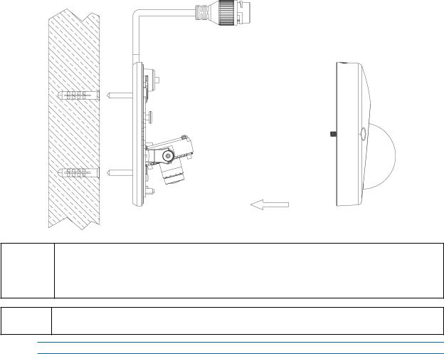
Procedure 2 Mounting the camera
Step Action
1Usethemountingtemplatetomark holes that correspondtothecamerabaseonthemountingsurface.
2Drill holes.
3Fastentheanchors tothemountingsurfacewithscrews.
4Securetheunit bottom casetothewall orceilingwithtappingscrews.
5Adjust theviewingangle.
8200-1631-03C0 |
11 |
IllustraProSeries InstallationandConfigurationGuide
6 Ensurethat thetopcoversafety wireis connectedandsecurely fit thetopcover.
Figure 10 Mounting the camera
Depending on the material of your mounting surface, you may require different screws and anchors than those as supplied. To prevent the unit from falling off, ensure that it is secured to a
WARNING firm place (ceiling slab or channel) with the safety wire (supplied) strong enough to sustain the total weight of the unit. Pay also attention to the finishing at the end of the wire. Never turn the lens more than 360°, which should disconnect or break internal cables.
CAUTION |
Ensure that the Safety wire is connected with one end to the ceiling and the other to the safety-cord |
screw of the unit. |
- End -
12 |
8200-1631-03C0 |
IllustraProSeries InstallationandConfigurationGuide
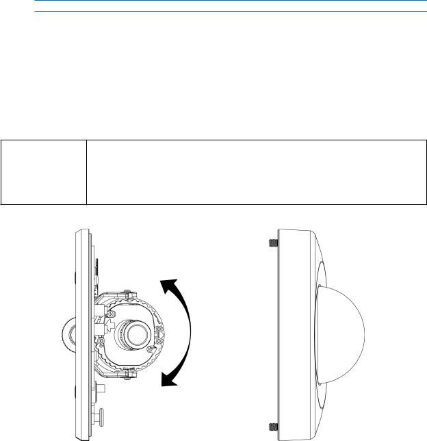
Procedure 3 Adjusting the Position
Theunit has threeaxes forpositioning, refertoFigure11onpage13. Whilemonitoring, adjust the positionas below.
Step Action
1PanAdjustment (A)ForWall Mount andTiltedCeilings:
a Rotatethelens base(maximum 140°)until youaresatisfiedwiththefieldof view.
2Horizontal Rotation(B):
a Rotate3D assembly inthebase. Donot turnassembly morethan354° as this assembly may causetheinternal cables totwist anddisconnect orbreak.
3Tilt Adjustment (C):
a Tilt thelens base(maximum 125° from thefrontal mountingsurface)until youaresatisfiedwiththefieldof view.
Limitation of three axis positions of lens centroid:
• Pan range: 140°
CAUTION
•Tilt range: 15° to 125° from frontal mounting surface
•Rotate (z-axis): 354°
Figure 11 Adjusting the position of the camera
8200-1631-03C0 |
13 |

IllustraProSeries InstallationandConfigurationGuide
Figure 12 Adjusting the position of the camera
NOTE |
For Compact camera series: |
||
The zoom level and focus are manually set in the factory. |
|||
|
|
||
|
|
|
|
|
|
|
|
|
|
- End - |
|
Procedure 4 Installing the desiccant
Step Action
1Removethepapers from theback of thedesiccant.
2Attachtotheinteriorsideof thecameracoveras seenintheimagebelow.
14 |
8200-1631-03C0 |

IllustraProSeries InstallationandConfigurationGuide
Figure 13 Location for desiccant application
- End -
Procedure 5 Locking the Camera
Step Action
1Useasoft, lint-freeclothtowipethedomecoverandremovefingerprints.
2Ensurethat thetopcoversafety wireis connectedandattachtheinnerlinerandtopcover.
-End -
Procedure 6 Powering up the camera
Connect thepowercabletothepowerplugs as followings:
•PoE: Connect theRJ-45jack toaPoE compatiblenetwork devicethat supplies power throughtheEthernet cable.
Note:ThePoE connectionshouldbeprovidedby aULListedproduct andtheconnections shall be madeinaccordancewithArticle800of theNEC orlocal regulations.
- End -
8200-1631-03C0 |
15 |

IllustraProSeries InstallationandConfigurationGuide
System requirements
Thetablebelow lists theminimum requirement toimplement andoperatethefollowingIllustraPro camera: Compact Mini Dome.
|
Table 14 System Requirements |
|
|
|
|
System |
|
|
Browser |
Microsoft Internet Explorer 9 or above, Firefox, Safari, Chrome |
|
|
|
|
Unit |
|
|
Power Supply |
PoE |
|
|
|
|
Networking |
|
|
Wired |
10/100BASE-T Ethernet (RJ-45 connector) |
|
NOTE: A switch is required for surveillance on multiple units. |
||
|
||
|
Compact Mini Dome System hardware |
|
CPU |
Intel Pentium 4 2.4GHz or equivalent |
|
|
|
|
RAM |
1 GB or above |
|
|
|
|
Display |
NVIDIA GeForce 6 Series or ATI Mobility Radeon 9500 |
|
|
|
NOTE |
All the installation and operations should comply with your local electricity safety rules. |
|
|
To avoid damage to the unit, never connect more than one type of power supply (PoE CAUTION IEEE802.3 Ethernet Class 2) at the same time. If using PoE, this camera is to be connecting
only to PoE networks without routing to heterogeneous devices.
16 |
8200-1631-03C0 |
IllustraProSeries InstallationandConfigurationGuide
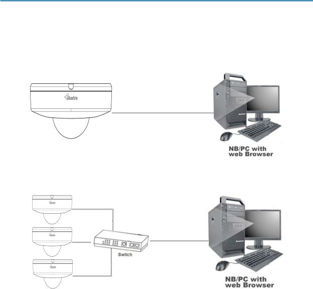
Network Topology
TheCompact Mini Domecameradelivers videoimages inreal-timeusingtheInternet andIntranet. It is equippedwithanEthernet RJ-45network interface.
Thefollowingimages illustratethenetwork topologies of thecameras.
Figure 15 Compact Mini Dome Cameras Network Topology Type I
Figure 16 Compact Mini Dome Cameras Network Topology Type II
17 |
8200-1631-03C0 |

IllustraProSeries InstallationandConfigurationGuide
Network Connection
Default IP Address
Sincethis is anetwork-basedunit, anIP address must beassignedat thevery first bootup. The default IP address of theunit is 192.168.1.168andsubmask is 255.255.255.0.
However, if youhaveaDHCP serverinyournetwork, theunit obtains anIP address automatically from theDHCP serversothat youdonot needtochangetheIP address of thecamera.
Note:If youassignthecameraaStatic IP address priortoDHCP beingenabled, thecamerafirst reboots forapproximately 30seconds andthenremains accessibleat its Static IP until it connects to aDHCP server.
•Connect toaPC directly: Directly connect thecameratoaPC usingastandardEthernet cable. This requires POE switchorinjector.
•ConnectingacameratoaLocal AreaNetwork (LAN): Toaddthecameratoanexisting LAN, connect thecameratothePOE huborswitchonyournetwork.
Figure 17 Network connection diagram
Default camera settings
Thefollowingtabledescribes thedefault camerasettings.
Network Settings |
Defaults |
DHCP |
Enabled |
|
|
Static IP Address |
192.168.1.168 |
|
|
Default Username |
admin |
|
|
Default Password |
admin |
|
|
Note:At first logintheuseris promptedtochangethedefault usernameandpassword.
18 |
8200-1631-03C0 |

IllustraProSeries InstallationandConfigurationGuide
Procedure 7 Connecting from a computer
Step Action
1Ensurethecameraandyourcomputerareinthesamesubnet.
2Check whetherif thenetwork is availablebetweentheunit andthecomputerby pingingthe default IP address.
a Start acommandprompt.
b Type“Ping192.168.1.168”. If themessage“Reply from…”appears, it means theconnectionis available.
3Start Internet ExplorerandenterIP address: 192.168.1.168. A loginwindow appears. Inthe window, enterthedefault username: adminandpassword: admintologin.
-End -
DHCP
Oninitial camerastartup, andafterahardwarefactory reset, Dynamic Host ConfigurationProtocol (DHCP)is enabledby default andremains enableduntil thecamerareceives eitheraDHCP address oris assignedaStatic IP address.
Procedure 8 Enable DHCP
Step Action
1Select Setup ontheWebUserInterfacebannertodisplay thesetupmenus.
2Select the TCP/IP tabinthe Basic Configuration menu.
3Select the Enable DHCP check box toenableDHCP anddisablemanual settings.
4Select Apply tosavethesettings.
Thecamerasearches foraDHCP server. If oneis foundit connects tothat server. If noconnection is madetoaDHCP serverwithintwominutes, thecameragoes tothedefault IP address 192.168.1.168, but continues tosearchforaDHCP address.
Note:If youassignthecameraaStatic IP address priortoDHCP beingenabled, thecamerafirst reboots forapproximately 30seconds andthenremains accessibleat its Static IP until it connects to aDHCP server.
- End -
Procedure 9 Disable DHCP
Step Action
1Select Setup ontheWebUserInterfacebannertodisplay thesetupmenus.
2Select the TCP/IP tabinthe Basic Configuration menu.
3Clearthe Enable DHCP check box todisableDHCP andallow manual settings tobe entered.
Thedefault settingis ‘Enabled’.
4If EnableDHCP has beendisabled:
8200-1631-03C0 |
19 |

|
|
IllustraProSeries InstallationandConfigurationGuide |
|
|
a |
EntertheIPv4Address inthe IPv4 Address text box intheform xxx.xxx.xxx.xxx.The |
|
|
|
default settingis ‘192.168.1.168’ |
|
|
b |
EntertheNetwork Mask inthe Network Mask text box xxx.xxx.xxx.xxx. Thedefault |
|
|
|
settingis ‘255.255.255.0’ |
|
|
c |
EntertheGateway IP address in Gateway text box xxx.xxx.xxx.xxx. |
|
|
d |
EnterthePrimary DNS Serverinthe Primary DNS Server text box xxx.xxx.xxx.xxx. |
|
5 |
Select Apply tosavethesettings. |
||
|
|
|
|
|
|
- End - |
|
Managing cameras with the Illustra Connect tool
InadditiontousingtheIE browsertoaccess yourcamera, youcanalternatively usetheprovided tool, IllustraConnect.
IllustraConnect is amanagement tool designedtomanageyournetwork cameras ontheLAN. It can:
•helpyoufindmultiplenetwork cameras
•set theIP addresses
•show connectionstatus
•managefirmwareupgrades
•bulk configuration
RefertoConfigurationonpage23forfurtherinformationregardingusingtheIllustraConnect tool for configuringthecameras.
Procedure 10 Connecting to the camera using Illustra Connect
Note:
IllustraConnect canonly discoverdevices onthesamesubnet as its host computer. Therefore, the cameraandthecomputerbeingusedtoconfigureit must beonthesamesubnet.
Step Action
1Usingacomputerwhichis connectedtothesamenetwork andsubnet, install theIllustra Connect software.
TheIllustraConnect softwareandtheIllustraConnect manual areavailabletodownloadon www.illustracameras.com
2Whentheinstallationis complete, runIllustraConnect.
It searches thenetwork anddisplays all compliant devices.
3Select thecamerayouwant toconfigure, locatingit by its uniqueMAC address.
4Right-click thecameraandselect LaunchWebGUI Configuration. ThecameraWebUser Interfacedisplays.
-End -
20 |
8200-1631-03C0 |
IllustraProSeries InstallationandConfigurationGuide
Procedure 11 Connecting to the camera using the static IP address
Step Action
1Thecameraattempts toobtainanIP Address from theDHCP Server. WhennoDHCP Serveris availablethecamerais assignedaStatic IP address of 192.168.1.168.
2OpenMicrosoft Internet ExplorerandentertheURLof thecameraas 192.168.1.168. The camerasigninpagedisplays.
Note:
Thecomputeryouusetoconfigurethecameramust haveanIP address onthesamesubnet.
- End -
Procedure 12 Logging on to the camera web user interface
Step Action
1Whenyouselect thecamera, thesigninpagedisplays. Select yourpreferredlanguagefrom thedrop-downmenu.
2Entertheusernameinthe Username text box. Thedefault usernameis admin.
3Enterthepasswordinthe Password text box. Thedefault passwordis admin.
4Select Log in.
Note:Thefirst timethat youaccess thecameraorafterafactory reset thefollowingtwopopup windows arevisible: A popupwindow that requests theuserto Define a Host ID andapopup window that requests theusertoselect a Security Type. Pleaserefertotheusermanual forfurther informationonthis.
5 TheLiveview pageis visible. This displays thecurrent view of thecamera.
Note:
At first logintheuseris promptedtochangethedefault usernameandpassword.
- End -
Procedure 13 Enabling the correct video orientation for a wall mounted camera
Step Action
1Logontothecamerawebuserinterface.
2Select Setup onthecamerawebuserinterfacebannertodisplay thesetupmenus.
3Select the Picture Basic tabfrom the Basic Configuration menu.
4Select therequired Orientation setting:
•Mirror
•Flip
5Thevideopaneupdates todisplay thenew settings.
-End -
8200-1631-03C0 |
21 |

IllustraProSeries InstallationandConfigurationGuide
Procedure 14 Selecting Corridor Mode
This provides abetterperspectivewhenviewingalongcorridor.
Step Action
1Select Setup ontheGUI bannertodisplay thesetupmenus.
2Select the Picture Basic tabfrom the Basic Configuration menu.
3Select Play tostart thevideostream if it is not already active.
4Select therequired Corridor Mode setting:
•None
•-90°
•+90°
5Thevideopaneupdates todisplay thenew settings.
-End -
22 |
8200-1631-03C0 |

IllustraProSeries InstallationandConfigurationGuide
Configuration
Thefollowingsections explainthehow youcanconfigureIllustraProcameras usingtheWebUser Interface.
Security Mode Profiles for First Time Connection
TheIllustraProcameras havefeatures that allow foroperationinaStandardSecurity modeorinan EnhancedSecurity mode.
TheEnhancedSecurity modeof operationis usedtocontrol changes tothecameracommunication protocols HTTP, HTTPS, FTP, andSMTP. Whenthecamerais inEnhancedSecurity mode, you requireacomplex sevencharacterAdministratorpasswordtomakechanges totheseprotocols.
RefertoSummary of Security Modes onpage24forfurtherinformationregardingthedifferences betweenStandardandEnhancedSecurity modes.
Accessing the Illustra Pro Series Camera Web User Interface
Usethefollowingproceduretoaccess thecameraWebUserInterface.
Procedure 15 Logging in to the Camera
Step Action
1RefertoNetwork Connectiononpage18fordetails onhow toconnect thecameratoyour network orcomputer.
2Whenyouselect thecamera, thesigninpagedisplays.
3Select yourpreferredlanguagefrom thedrop-downmenu. Thedefault languageis English.
4Enterthedefault usernameandpasswordwhenprompted - Username: admin, Password: admin.
5Click Log in. ThecameraWebUserInterfacedisplays. Thefirst timethat youaccess the camera, orafterafactory reset, youarepromptedto Define a Host ID and Select a Security Type.
•Define a Host ID: Theadminusermust entera6charactercodefor theHost ID that includes bothletters and/ornumbers. This unique passwordcanbeusedtoaccess theoperatingsystem files. The HostID is not storedonthecameraforsecurity reasons andmust be presentedtoIllustraTechnical Support whenremoteaccess tothe operatingsystem is required.
•Select a Security Type: StandardSecurity orEnhancedSecurity.If youarekeepingStandardSecurity, it is best practicetousethe ChangePasswordcheck box toimmediately changethedefault passwordtooneuniquetoyoursurveillancesystem.
6Optional - If youselect theEnhancedSecurity option, youarerequiredandinstructedto createacomplex password.
Note:Thepasswordmust meet thefollowingrequirements: Beaminimum of sevencharacters long.
Haveat least onecharacterfrom at least threeof thefollowingcharactergroups:
23 |
8200-1631-03C0 |

IllustraProSeries InstallationandConfigurationGuide
•Upper-caseletters
•Lower-caseletters
•Numeric characters
•Special characters
Note:Oncetheabovesteps arecomplete, theLiveview pageis visible. This displays thecurrent view of thecamera.
- End -
Summary of Security Modes
Standard Security:
•Changes tocommunicationprotocols areavailabletoall users withappropriate privileges.
•Passwords complexity is set torequireminimum of any 5characters.
•Authenticationmethodis set tobasic by default.
ENHANCED SECURITY
•UnsecureProtocols aredisabledby default until enabledby auser.
•Whenyouselect enhancedsecurity youmust changethedefault 'admin' username andpassword.
•Discovery protocols aredisabledby default until enabledby auser.
•Changes intheprotocols areonly beavailabletoauserwithadministrativeprivileges andrequirethat usertoreentertheirpassword.
•Passwords forall accounts will meet thefollowingpasswordcomplexity requirements:
•Minimum characters: 8
•Thepasswordmust haveat least onecharacterfrom aminimum of threeof thefollowingcharactergroups:
aUppercaseletters
bLowercaseletters
cNumeric characters
dSpecial characters
eChangingprotocols requireanadministratortore-entertheirpassword
•Authenticationmethodis set toDigest by default.
Changing the Camera Web User Interface Language
UsethefollowingproceduretochangethelanguageusedinthecameraWebUserInterface.
Procedure 16 Change the Camera Web User Interface Language
Step Action
1Openthecamerasigninpage. If youarealready loggedintotheWebUserInterface, select LogOff todisplay thesigninpage.
2Select yourpreferredlanguagefrom thedrop-downmenu:
8200-1631-03C0 |
24 |

IllustraProSeries InstallationandConfigurationGuide
•English
•Arabic
•Czech
•Danish
•German
•Spanish
•French
•Hungarian
•Italian
•Japanese
•Korean
•Dutch
•Polish
•Portuguese
•Swedish
•Turkish
•ChineseSimplified
•ChineseTraditional
•Russian
Thedefault languageis English.
3EntertheUsername.
4EnterthePassword.
5Select Login.
ThecamerawebUserInterfacedisplays intheselectedlanguage.
- End -
25 |
8200-1631-03C0 |
IllustraProSeries InstallationandConfigurationGuide
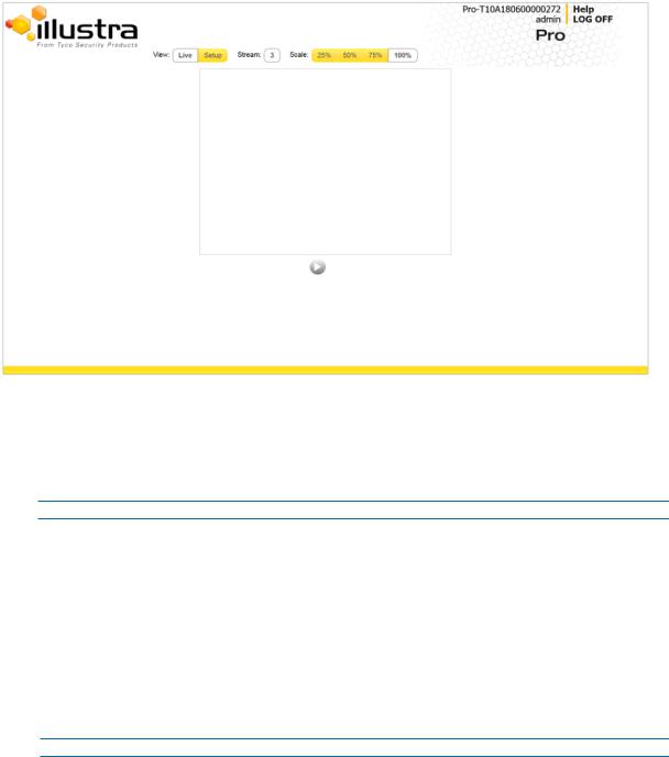
Live menu
WhenyoulogintotheIllustraWebUserInterface, the Live menuappears, as seeninFigure18on page26.
Whenanadminuserlogs inforthefirst timethe Live menupagedisplays, but afterthis eachtime youloginthe Stream pageonthe Video menudisplays.
Figure 18 Live menu page
Displaying the Live View Page
Display thelivecameraview page.
Procedure 17 Display Live View Page
Step Action
1Select Live intheWebUserInterfacebanner. TheLiveview pagedisplays.
2Select avideostream from Stream toview.
3Select apercentagefrom Scale tochangethedisplay sizeof thevideopane:
•25%
•50%
•75%
•100%
Thedefault settingis 50%.
- End -
26 |
8200-1631-03C0 |

IllustraProSeries InstallationandConfigurationGuide
Accessing the Setup Menus from Live View
Setupmenus withintheWebUserInterfacearerestrictedby useraccount access levels. Referto Appendix A: UserAccount Access onpage98fordetails onthefeatures whichareavailabletoeach role.
Procedure 18 Access Setup Menus from Live View
Step Action
1 |
Onthe Live menu, click the Setup tab. |
Note:Whenanadminuserlogs inforthefirst timetheLivenmenudisplays. Afterthis, oneachlogin theStream pageontheVideomenudisplays.
- End -
8200-1631-03C0 |
27 |
IllustraProSeries InstallationandConfigurationGuide
Quick Start Menu
Whenyouselect theQuick Start menu, theBasic ConfigurationPagedisplays, as showninFigure 19onpage28.
Note:Whenanadminuserlogs inforthefirst timetheBasic Configurationpagedisplays. Afterthis, oneachlogintheVideo> Streams pagedisplays.
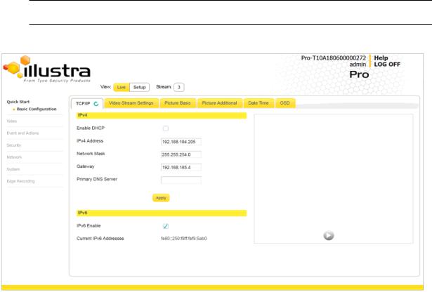
Figure 19 Basic Configuration Menu
Basic Configuration
The Basic Configuration menuprovides access tothemost commonfeatures requiredwhen settingupacameraforthefirst timeandis only availabletoan‘admin’ user. Thefollowingtabs are displayed:
•TCP/IP
•VideoStream Settings
•PictureBasic
•PictureAdditional
•DateTime
•OSD
28 |
8200-1631-03C0 |

IllustraProSeries InstallationandConfigurationGuide
TCP/IP
ConfiguretheIPv4andIPv6network settings onthecamera.
Note:Whenyouperform afactory reset orreboot theunit searches forthelast knownIP address. If this is not availableit reverts tothedefault IP address of 192.168.1.168. This couldresult duplicate IP addresses. RefertoQuick Start Menuonpage28formoreinformation.
DHCP
Oninitial camerastartup, andafterahardwarefactory reset, Dynamic Host ConfigurationProtocol (DHCP)is enabledby default andremains enableduntil thecamerareceives eitheraDHCP address oris assignedaStatic IP address.
Procedure 19 Enable DHCP
Step Action
1Select Setup ontheWebUserInterfacebannertodisplay thesetupmenus.
2Select the TCP/IP tabinthe Basic Configuration menu.
3Select the Enable DHCP check box toenableDHCP anddisablemanual settings.
4Select Apply tosavethesettings.
Thecamerasearches foraDHCP server. If oneis foundit connects tothat server. If noconnection is madetoaDHCP serverwithintwominutes, thecameragoes tothedefault IP address 192.168.1.168, but continues tosearchforaDHCP address.
Note:If youassignthecameraaStatic IP address priortoDHCP beingenabled, thecamerafirst reboots forapproximately 30seconds andthenremains accessibleat its Static IP until it connects to aDHCP server.
- End -
Procedure 20 Disable DHCP
Step Action
1Select Setup ontheWebUserInterfacebannertodisplay thesetupmenus.
2Select the TCP/IP tabinthe Basic Configuration menu.
3Clearthe Enable DHCP check box todisableDHCP andallow manual settings tobe entered.
Thedefault settingis ‘Enabled’.
4If EnableDHCP has beendisabled:
a EntertheIPv4Address inthe IPv4 Address text box intheform xxx.xxx.xxx.xxx.The default settingis ‘192.168.1.168’
b EntertheNetwork Mask inthe Network Mask text box xxx.xxx.xxx.xxx. Thedefault settingis ‘255.255.255.0’
c EntertheGateway IP address in Gateway text box xxx.xxx.xxx.xxx.
d EnterthePrimary DNS Serverinthe Primary DNS Server text box xxx.xxx.xxx.xxx.
5Select Apply tosavethesettings.
8200-1631-03C0 |
29 |

IllustraProSeries InstallationandConfigurationGuide
- End -
IPv4
ConfiguretheIPv4network settings forthecamera.
Procedure 21 Configure the IPv4 Settings
Step Action
1Select Setup ontheWebUserInterfacebannertodisplay thesetupmenus.
2Select the TCP/IP tabinthe Basic Configuration menu.
3Select the Enable DHCP check box toenableDHCP anddisablemanual settings. OR
Clear Enable DHCP todisableDHCP andallow manual settings tobeentered. Thedefault settingis ‘Enabled’.
4If EnableDHCP has beendisabled:
a Enterthe IPv4 Address intheIPv4Address text box intheform xxx.xxx.xxx.xxx. Thedefault settingis ‘192.168.1.168’
b Enterthe Network Mask intheNetwork Mask text box xxx.xxx.xxx.xxx. Thedefault settingis ‘255.255.255.0’
c Enterthe Gateway IP address inGateway text box xxx.xxx.xxx.xxx.
d Enterthe Primary DNS Server inthePrimary DNS Servertext box xxx.xxx.xxx.xxx.
5Select Apply tosavethesettings.
- End -
IPv6
EnableordisableIPv6onthecamera.
Procedure 22 Enable/Disable IPv6
Step Action
1Select Setup ontheWebUserInterfacebannertodisplay thesetupmenus.
2Select the TCP/IP tabinthe Basic Configuration menu.
3Select the IPv6 Enable check box toenableIPv6onthecamera. OR
Clearthe IPv6 Enable check box todisableIPv6onthecamera. Thedefault settingis ‘Enabled’.
If IPv6is enabledtheLink Local andDHCP address display beside‘Current IPv6 Addresses’ if available.
-End -
Video Stream Settings
Youcanconfigurethreevideostreams onthecamera: Stream 1, Stream 2, andStream 3.
30 |
8200-1631-03C0 |
Loading...