


 Loading...
American Dynamics ADCI400-B041, ADCI400-D011, ADCI400-D022, ADCI400-D031, ADCI400-D032 Installation Manual
...Installation & Operation Guide
Version1.1
illustra 400 IP Camera
Part Number: 8200-2745-01 A0
Copyright
Under copyright laws, the contents of this manual may not be copied, photocopied, reproduced, translated or reduced to any electronic medium or machine-readable form, in whole or in part, without prior written consent of Tyco International Ltd. © 2010 and its Respective Companies. All Rights Reserved.
American Dynamics
6600 Congress Avenue
Boca Raton, FL 33487 U.S.A.
Trademarks
The trademarks, logos, and service marks displayed on this document are registered in the United States [or other countries]. Any misuse of the trademarks is strictly prohibited and Tyco International Ltd. will aggressively enforce its intellectual property rights to the fullest extent of the law, including pursuit of criminal prosecution wherever necessary. All trademarks not owned by Tyco International Ltd. are the property of their respective owners, and are used with permission or allowed under applicable laws.
Product offerings and specifications are subject to change without notice. Actual products may vary from photos. Not all products include all features. Availability varies by region; contact your sales representative.
|
Table Of Contents |
|
SAFETY PRECAUTIONS ............................................................................. |
7 |
|
1. PRODUCT FEATURES............................................................................. |
8 |
|
1.1 PRODUCT INSTRUCTIONS ..................................................................... |
8 |
|
1.2 PRODUCT FEATURES ........................................................................... |
9 |
|
1.3 TECHNICAL SPECIFICATIONS............................................................... |
10 |
|
2. DESCRIPTION OF THE SURFACE ....................................................... |
18 |
|
2.1 THE ILLUSTRA 400 IP BOX CAMERA (POE) ...................................... |
18 |
|
2.2 THE ILLUSTRA 400 FIXED IP INDOOR MINI-DOME (POE) ...................... |
20 |
|
2.3 THE ILLUSTRA 400 FIXED IP OUTDOOR MINI-DOME (POE)................... |
21 |
|
2.4 THE ILLUSTRA 400 BULLET IP CAMERA INDOOR/OUTDOOR (POE) ........ |
22 |
|
2.5 THE RESET BUTTON .......................................................................... |
24 |
|
2.6 THE ALARM WIRING DIAGRAMS ........................................................... |
25 |
|
2.7 THE USB FUNCTION .......................................................................... |
28 |
|
3. INSTALLATION ...................................................................................... |
29 |
|
3.1 HARDWARE INSTALLATION .................................................................. |
29 |
|
3.2 PLACING A DESICCANT PACK INSIDE THE CAMERA ............................... |
29 |
|
3.3 UPDATING SYSTEM SOFTWARE........................................................... |
30 |
|
4. Network Configuration .......................................................................... |
31 |
|
4.1 CABLE CONNECTIONS ........................................................................ |
31 |
|
4.1.1 Connect to a computer ................................................................................................. |
31 |
|
4.1.2 Connect to a LAN Hub (INTRANET) ......................................................................... |
31 |
|
4.2 CONFIGURE YOUR IP CAMERA NETWORK SETTINGS ........................... |
32 |
|
4.2.1 Enable DHCP Function ................................................................................................ |
32 |
|
4.2.2 Set IP Address .............................................................................................................. |
32 |
|
4.3 TCP/IP COMMUNICATION SOFTWARE ................................................. |
33 |
|
4.4 TCP/IP INSTALLATION ........................................................................ |
35 |
|
4.5 TCP/IP CONFIGURATION SETTING....................................................... |
36 |
|
4.6 CONNECTION TESTING ....................................................................... |
37 |
|
5. Operation Instructions for the Network............................................... |
39 |
|
5.1 MICROSOFT INTERNET EXPLORER ...................................................... |
40 |
|
5.1.1 |
Connecting the IP camera............................................................................................ |
40 |
5.1.2 |
Live Video................................................................................................................... |
40 |
5.1.3 |
Setup ........................................................................................................................... |
44 |
4 |
Installation and Operation Guide |

Installation and Operation Guide |
|
6. ADVANCED OPERATION ...................................................................... |
88 |
7. SPECIFICATIONS................................................................................... |
92 |
APPENDIX A. –IP camera UPnP How To ................................................. |
95 |
APPENDIX B. –Register as a DDNS member ........................................ |
103 |
APPENDIX C. –The Icons in the Analog Video OSD ............................ |
106 |
Figure List |
|
Figure 2.1 Front Panel and Rear Panel.............................................................................................. |
18 |
Figure 2.2 Flank Panel:.......................................................................................................................... |
19 |
Figure 2.3 Fixed IP indoor mini-dome................................................................................................ |
20 |
Figure 2.3 The IP Out-door mini-dome .............................................................................................. |
21 |
Figure 2.5 The internal view of Bullet Camera................................................................................. |
22 |
Figure 2.6 The external view of Bullet Camera................................................................................ |
22 |
Figure 2.7 The PCB board..................................................................................................................... |
23 |
Figure 2.8 Illustra 400 IP BOX CAMERA (PoE)................................................................................. |
25 |
Figure 2.9 Illustra 400 Fixed IP Indoor/ Outdoor Mini-Dome (PoE) ............................................. |
26 |
Figure 2.10 Illustra 400 Bullet IP Camera Indoor/outdoor (PoE).................................................. |
27 |
Figure 2.11 The USB function .............................................................................................................. |
28 |
Figure 4.1 Physical specifications of the RJ-45 cable for Ethernet............................................ |
31 |
Figure 4.3 Connect to a LAN Hub ....................................................................................................... |
31 |
Figure 4.4 TCP/IP Communication Software .................................................................................... |
33 |
Figure 4.5 Network Connections......................................................................................................... |
33 |
Figure 4.6 Properties ............................................................................................................................. |
34 |
Figure 4.7 Select Internet Protocol..................................................................................................... |
34 |
Figure 4.8 TCP/IP Installation............................................................................................................... |
35 |
Figure 4.9 TCP/IP configuration setting ............................................................................................ |
36 |
Figure 4.10 Select Command Prompt ................................................................................................ |
37 |
Figure 5.2 Login ...................................................................................................................................... |
40 |
Figure 5.3 Live VideoAJAX................................................................................................................. |
41 |
Figure 5.5 Zoom function...................................................................................................................... |
43 |
Figure 5.6 Setup Wizard ........................................................................................................................ |
44 |
Figure 5.7 Setup LAN Settings ............................................................................................................ |
44 |
Figure 5.8 Setup Internet Settings ...................................................................................................... |
45 |
Figure 5.9 Setup DDNS Settings ......................................................................................................... |
45 |
Figure 5.10 Camera Settings................................................................................................................ |
45 |
Figure 5.11 – Setup Time Zone ............................................................................................................ |
46 |
Figure 5.12 – Setup Complete.............................................................................................................. |
46 |
Figure 5.13 – Image Setup .................................................................................................................... |
47 |
Figure 5.14 – Audio and Video............................................................................................................. |
49 |
Figure 5.15 Audio In/Out ....................................................................................................................... |
51 |
Figure 5.16................................................................................................................................................ |
51 |
Figure 5.17 Privacy Mask Area of Video Setting ............................................................................. |
52 |
Figure 5.18 Network Setup ................................................................................................................... |
53 |
Figure 5.19 PPPoE Settings ................................................................................................................. |
54 |
|
5 |
Figure 5.20 Port Detail ........................................................................................................................... |
55 |
Figure 5.21 Traffic................................................................................................................................... |
57 |
Figure 5.22 Dynamic DNS..................................................................................................................... |
58 |
Figure 5.23 HTTPS.................................................................................................................................. |
59 |
Figure 5.24 Access List ......................................................................................................................... |
61 |
Figure 5.25 Time and Date.................................................................................................................... |
63 |
Figure 5.26 DI and DO............................................................................................................................ |
65 |
Figure 5.27 ICR........................................................................................................................................ |
66 |
Figure 5.28 RS-485 ................................................................................................................................. |
67 |
Figure 5.29 User...................................................................................................................................... |
69 |
Figure 5.30 Maintenance....................................................................................................................... |
70 |
Figure 5.31 Upgrade Firmware ............................................................................................................ |
71 |
Figure 5.32 Language Setup ................................................................................................................ |
72 |
Figure 5.33 Motion Detection............................................................................................................... |
73 |
Figure 5.34 Event Setup ........................................................................................................................ |
74 |
Figure 5.35 Server .................................................................................................................................. |
75 |
Figure 5.36 Media.................................................................................................................................... |
78 |
Figure 5.37 Event .................................................................................................................................... |
80 |
Figure 5.38 Recording ........................................................................................................................... |
82 |
Figure 5.39 SD Card ............................................................................................................................... |
84 |
Figure 5.40 Device Info.......................................................................................................................... |
85 |
Figure 5.41 System Log ........................................................................................................................ |
86 |
Figure A-1 UPnP Setup Flow Chart .................................................................................................... |
95 |
Figure B-1 ............................................................................................................................................... |
103 |
Figure B-2 ............................................................................................................................................... |
103 |
Figure B-3 ............................................................................................................................................... |
104 |
Figure B-4 ............................................................................................................................................... |
104 |
Figure B-5 ............................................................................................................................................... |
105 |
Figure B-6 ............................................................................................................................................... |
105 |
6 |
Installation and Operation Guide |

WARNING
At close range, infrared light can seriously damage a person's vision. Install this illuminator with a minimum safety zone of 1.22m ( 4 ft. ) between the illuminator and the closest possible human contact.
Note: 1.22M ( 4 FT. ) IS THE ACTUAL MEASUREMENT OF THE STRENGTH OF THE IR
ILLUMINATORS THAT ARE BEING USED.
Note: CAMERA STARTS UP IN BLACK & WHITE BECAUSE THE IR ILLUMINATOR IS DISCONNECTED.
For safety reasons, the IR Illuminator is disconnected at the factory. If the IR Illuminator were to accidentally trigger during install, it may pose a hazard to those within 4 feet. Once the camera is installed, reconnect the power lead (see manual). Ensure that you do not cover the photo cell (see manual) after power is reconnected as that may trigger the IR illuminator.
SERVICE WARNING
DO NOT LOOK DIRECTLY INTO AN OPERATONAL IR ILLUMINATOR.
Since IR light is invisible to the human eye, the only method of verifying a malfunctioning IR illuminator is to observe the picture at the video output location.
SAFETY PRECAUTIONS
All the following safety and operational instructions to prevent harm or injury to the operator(s) or other persons should be read carefully before the unit is activated.
WARNING
To prevent fire or shock hazard, avoid exposing this unit to rain or moisture.
Do not block ventilation openings.
Do not place anything on top of the unit that might spill or fall into it.
Do not attempt to service this unit yourself, as opening or removing covers may expose you to dangerous voltage or other hazards. Please refer all servicing to your distributor / retailer.
Do not use liquid cleaners or aerosols for cleaning.
To prevent fire or electric shock, do not overload wall outlets or extension cord.
PoE warning: If the PoE injector is used instead of the supplied power adaptor, all of the wiring to and from the injector must be routed/ installed inside a building/ plant and never routed/ installed outside of the building/ plant.
Please only select a power adapter or power certified by UL and marked at 24Vac / 60 Hz, minimum 1A, class 2 or LPS.
CAUTION
RISK OF EXPLOSION IF BATTERY IS REPLACED BY AN INCORRECT TYPE. DISPOSE OF USED BATTERIES ACCORDING TO THE INSTRUCTIONS.
7 |
Installation and Operation Guide |
1. PRODUCT FEATURES
1.1 Product Instructions
The WDR IP Camera
This ADCi400 series is a high performance Network Camera which is equipped with a high resolutions CMOS sensor and a resolution of up to 896x720 (D2). This powerful new series enables you to see fresh images in fine detail aided by a spectrum of high resolutions plus WDR technology that combats problems like capturing images against backgrounds of bright light. In addition the series is equipped with the dynamic H. 264 video compression format, the compression codec which ensures top image quality at a low bit rate. The 3GPP installed mobile phone helps you see live scenes via the Internet as well.
Following are the special powers featured in this series.
D2 / 896x720 pixels
The ADCi400 series lets you view the video feed with a large field of high resolutions at D2 / 896x720 pixels that provide you with clear images in great detail.
WDR (Wide Dynamic Range)
Besides, the ADCi400 series provides WDR technology which is aimed at coping with problems like poor quality images shot against a strong backlight. WDR uses two shutter speeds in alternative video fields, high and normal, and combines these two fields into one frame. It allows every detail to be captured accurately, even if one portion is bright while other portions are dark. As a result, combined fields yield a frame of high quality images.
H.264 compression
Currently, the H.264 is the most common and dynamic video compression format and a powerful compression codec which delivers superior image quality at a low bit rate.
8 |
Installation and Operation Guide |

Installation and Operation Guide
3GPP
Users can view a live scene via the Internet with a 3GPP installed mobile phone.
(Note: The 3G network bandwidth is limited; you can't use too large video size on your cell phone.) Video Settings:
Video Profile 1
Maximum frame rate: 3 fps
Intra Frame Period: 1 S
Constant bit rate: 64 Kbps
In short, the ADCi400 series provides quality images and professional surveillance functions for comprehensive security applications.
1.2 Product Features
Adopts TI TMS320DM365 digital media processor.
Sony CMOS sensor.
Simultaneous H.264 and MJPEG video compression.
Three multi-profile applications: Selectable resolutions, frame rates, qualities, and image chopping.
Supports WDR.
Built-in IR-cut filter provides high quality images in low light conditions.
Min. illumination: 0.2 Lux at F1.4.
Two-way audio.
3GPP mobile surveillance.
Advanced motion detection (512 zones. Sensitivity: 0 -100 %).
Built-in SD / SDHC card for schedule and alarm recording.
Supports ONVIF.
Full range of power options: DC12V / AC24V / PoE (IEEE 802.3af).
9

1.3 Technical Specifications
Camera: |
Illustra 400 IP BOX |
|
CAMERA |
||
|
||
Image sensor |
1/3” Sony IMX035 CMOS sensor |
|
Minimum Illumination |
Color: 0.2 Lux @F1.4 |
|
B/W: 0.01 Lux |
||
|
||
Lens |
computar 2.9~8.2mm Vari-focal |
|
auto iris DC drive, CS-mount lens |
||
|
||
Shutter time |
1/60 ~ 1/2,000 sec (NTSC) |
|
1/50~1/2,000sec (PAL) |
||
|
||
|
|
|
Auto iris type |
DC drive |
|
Exposure |
AES/Auto-IRIS |
|
Day & Night |
Mechanical IR filter |
|
Day & Night mode |
Auto/Day/Night/Schedule |
|
Light Sensor |
Yes |
|
WDR |
100dB, 9 levels (adjustable level |
|
settings) |
||
|
||
2D Noise Filter |
Yes |
|
Video Signal |
|
|
Video output type |
BNC |
|
Video output level |
1.0 Vpp +/-10% 75Ω, composite, |
|
Negative (RCA unbalanced) |
||
|
||
Synchronization |
Internal |
|
Video Codec |
|
|
Video compression |
H.264 MJPEG |
|
|
NTSC: |
|
|
896x720 (D2), 720x480 (D1), |
|
Resolutions |
352x240(CIF), 176x120(QCIF) |
|
PAL: |
||
|
||
|
896x720 (D2), 720x576 (D1), |
|
|
352x288(CIF), 176x144(QCIF) |
|
Video streaming |
Simultaneous multi-profile video |
|
stream |
||
|
||
Profiles |
3 |
|
Video Codec – H.264 |
|
|
H.264 Frame rate |
Up to 30 fps at 720x480 (D1) |
|
H.264 frame rate control |
Yes |
|
H.264 bit rate control |
Yes |
|
H.264 quality level |
5 |
|
IP Ratio Changeable |
Yes |
|
Variable bit rate |
CBR/VBR |
|
Video Codec – MJPEG |
|
|
MJPEG frame rate |
Up to 30 fps at 720x480 (D1) |
|
MJPEG frame rate |
Yes |
|
control |
||
|
||
MJPEG quality level |
5 |
|
|
|
|
Image |
|
|
AWB |
Auto/Indoor/Outdoor/Fluorescent |
|
Mirror |
Yes |
|
Flip |
Yes |
|
|
Auto/Manual |
|
Exposure Time |
1/2000, 1/1500, 1/1000, 1/750, |
|
1/500, 1/250, 1/120, 1/60, 1/30, |
||
|
||
|
1/15, 1/7.5, 1/4, 1/2 |
|
AGC |
8X/ 16X/ 32X/ 64X |
|
Saturation |
Adjustable |
|
Sharpness |
Adjustable |
|
Contrast |
Adjustable |
|
Brightness |
Adjustable |
|
Privacy Area |
Programmable 3 independent |
10
|
zones |
|
Motion Detection |
Programmable 512 independent |
|
zones |
||
|
||
Motion Detection |
0~100% |
|
Sensitivity |
||
|
||
Motion Detection |
0~100% |
|
Percentage |
||
|
||
OSD |
IP Address/Date/Time/ICON |
|
Day/Night Control |
Auto/Day/Night/Schedule |
|
Timestamp |
Title/Date/Time |
|
SMART Codec |
Yes (HIGH PROFILE OF H.264) |
|
Software Platform |
|
|
Operation System |
Linux 2.6 kernel |
|
System Integration |
|
|
System Requirement |
Microsoft Windows XP |
|
Microsoft Windows 7 |
||
|
||
Compatible Browser |
Mozilla FireFox, IE 6.x or above, |
|
Chrome |
||
|
||
Cell phone |
3GPP streaming viewer |
|
Network API/SDK |
API / ONVIF |
|
Alarm |
|
|
|
Motion Detection |
|
|
Schedule |
|
Alarm triggers |
Alarm input |
|
|
Ethernet loss |
|
|
Network/Remote digital alarm input |
|
Tamper proof |
Yes |
|
Alarm video buffers |
48MB pre-alarm and post alarm |
|
Hardware |
|
|
FTP file format |
JPG Snapshot/AVI Clip |
|
SMTP file format |
JPG Snapshot/AVI Clip |
|
SAMBA file format |
JPG Snapshot/AVI Clip |
|
Schedule file format |
JPG Snapshot/AVI Clip |
|
Schedule counts |
7 |
|
Hardware |
|
|
|
Texas Instruments DaVinci 365 |
|
Processors |
High performance 32-bit RISC |
|
|
CPU |
|
DDRII memory |
DDRII 256MBytes |
|
Flash memory |
32MBytes |
|
Real-time clock |
Built-in |
|
Real-time clock battery |
Built-in |
|
Watchdog |
Built-in |
|
Firmware upgrade |
Yes, SD Card/ HTTP |
|
Approvals |
|
|
FCC |
Yes |
|
CE |
Yes |
|
RoHS |
Yes |
|
Power |
|
|
DC 12V |
Yes |
|
AC 24V |
Yes |
|
PoE |
Yes (IEEE 802.3af) |
|
Physical Property |
|
|
Height |
56.5mm |
|
Width |
68mm |
|
Length |
114.5mm |
|
Weight |
360 g |
|
MTBF |
1350000Hours |
|
Operating Temperature |
0 to 50 (32 to 122 ) |
|
Operations Humidity |
30% to 80 % |
|
Storage temperature |
-20 to 60 (-4 to 140 ) |
Installation and Operation Guide
Installation and Operation Guide
Audio Signal
Number of tracks |
Mono 1 channel |
|
Audio Codec |
G.711u |
|
G.726 |
||
|
||
Audio sample rate |
8kHz |
|
Audio bit rate |
G.711u 64kbps |
|
G.726 32kbps |
||
|
||
Audio output |
1K ohms |
|
Audio input |
Built-in Microphone or LINE in10k |
|
ohms 1.0Vpp |
||
|
||
2-Way Audio |
Yes |
|
USB |
|
|
Type |
2.0 * 1 (A-Type) |
|
Network settings |
Yes (Window XP compatible) |
|
configurable |
||
|
||
Network |
|
|
Ethernet |
Ethernet (10/100 Base-T), RJ-45 |
|
connector |
||
|
||
MDIX |
Yes |
|
|
3-Level password protection |
|
Security |
IP address filtering |
|
User access log |
||
|
||
|
HTTPS |
|
|
IPv4, HTTPS, HTTP, TCP, UDP, |
|
Protocol |
RTP/RTCP/RTSP, DHCP, NTP, |
|
FTP, SMTP, UPnP, ICMP, ARP, |
||
|
||
|
DDNS, PPPoE, SAMBA |
|
Management console |
Full function |
|
Throughput |
16M bit/second |
|
Bandwidth control |
Yes |
|
Simultaneous users |
10 |
|
DDNS |
Dyndns |
|
IE recording support |
Yes |
|
HTTPS |
|
|
Public-key cryptography |
RSA |
|
Private key length |
1024 bit |
|
Self-signed certificate |
Manually and automatically |
|
Create certificate |
Yes |
|
request |
||
|
||
Install signed certificate |
Yes |
|
Simultaneously HTTP |
Yes |
|
and HTTPS |
||
|
||
Storage |
|
|
SD Card Support |
MMC/SD/SDHC 2.0 32MB~32GB |
|
Pre-alarm |
Yes |
|
File system |
FAT/ FAT32 |
|
Recording format |
JPG/AVI |
|
Network play-back |
Yes |
|
|
A-Data |
|
SD card brand verified |
PQI |
|
|
Toshiba |
|
Transcend |
|
|
APacer |
|
|
Photo Fast |
|
Multi-lingual User Interface |
||
|
English |
|
|
Traditional Chinese |
|
|
Simplified Chinese |
|
|
Czech |
|
|
Dutch |
|
|
Finland |
|
|
French |
|
Languages |
German |
|
Italian |
||
|
||
|
Polish |
|
|
Portuguese |
|
|
Spain |
|
|
Swedish |
|
|
Hungarian |
|
|
Rumanian |
|
|
Turkish |
|
Device Indicator |
|
|
Ethernet Link |
Yes |
|
Ethernet Active |
Yes |
|
System Operation |
Yes |
|
Configuration Maintenance |
||
Backup Configuration |
Yes (Browser) |
|
Restore Configuration |
Yes (Browser) |
|
Factory Default |
Yes |
|
System Log |
Yes |
|
Accessories |
|
|
|
USB cable |
|
Accessories |
CD-Rom |
|
Power Adapter |
||
|
||
|
Quick installation guide |
|
PTZ Support |
|
|
Digital PTZ |
Yes |
|
I/O Ports |
|
|
USB |
2.0 x1 |
|
|
|
|
Factory Reset |
Yes |
|
Alarm input |
2 +/ - |
|
Alarm output |
1 +/ - |
|
Audio I/O |
1 / 1 |
|
Ground |
1 |
|
DC-OUT |
1 |
|
Mount / Bracket |
|
|
Pendant Bracket |
Yes |
|
Ceiling Mount |
Yes |
|
Gooseneck |
Yes |
|
11

Camera: |
Illustra 400 Fixed IP |
|
Indoor Mini-Dome |
||
|
||
Image sensor |
1/3” Sony IMX035 CMOS sensor |
|
Minimum Illumination |
Color: 0.2 Lux @F1.4 |
|
B/W: 0.01 Lux |
||
|
||
Shutter time |
1/60~1/2,000 sec (NTSC) |
|
1/50~1/2,000sec (PAL) |
||
|
||
Exposure |
AES/Auto-IRIS |
|
|
|
|
Day & Night |
Mechanical IR filter |
|
Day & Night mode |
Auto/Day/Night/Schedule |
|
Light Sensor |
Yes |
|
WDR |
100dB, 9 levels (adjustable level |
|
settings) |
||
|
||
|
|
|
IR illuminators |
Effective up to 15 meters |
|
2D Noise Filter |
Yes |
|
Video Signal |
|
|
Video output type |
RCA |
|
Video output level |
1.0 Vpp +/-10% 75Ω, composite, |
|
Negative (RCA unbalanced) |
||
|
||
Synchronization |
Internal |
|
Video Codec |
|
|
Video compression |
H.264 MJPEG |
|
|
NTSC: |
|
|
896x720 (D2), 720x480 (D1), |
|
Resolutions |
352x240(CIF), 176x120(QCIF) |
|
PAL: |
||
|
||
|
896x720 (D2), 720x576 (D1), |
|
|
352x288(CIF), 176x144(QCIF) |
|
Video streaming |
Simultaneous multi-profile video |
|
stream |
||
|
||
Profiles |
3 |
|
Video Codec – H.264 |
|
|
H.264 Frame rate |
Up to 30 fps at 720x480 (D1) |
|
H.264 frame rate control |
Yes |
|
|
|
|
H.264 bit rate control |
Yes |
|
H.264 quality level |
5 |
|
IP Ratio Changeable |
Yes |
|
Variable bit rate |
CBR/VBR |
|
Video Codec – MJPEG |
|
|
MJPEG frame rate |
Up to 30 fps at 720x480 (D1) |
|
MJPEG frame rate |
Yes |
|
control |
||
|
||
MJPEG quality level |
5 |
|
|
|
|
Image |
|
|
AWB |
Auto/Indoor/Outdoor/Fluorescent |
|
Mirror |
Yes |
|
Flip |
Yes |
|
|
Auto/Manual |
|
Exposure Time |
1/2000, 1/1500, 1/1000, 1/750, |
|
1/500, 1/250, 1/120, 1/60, 1/30, |
||
|
||
|
1/15, 1/7.5, 1/4, 1/2 |
|
AGC |
8X/ 16X/ 32X/ 64X |
|
Saturation |
Adjustable |
|
Sharpness |
Adjustable |
|
Contrast |
Adjustable |
|
Brightness |
Adjustable |
|
Privacy Area |
Programmable 3 independent |
|
zones |
||
|
||
Motion Detection |
Programmable 512 independent |
|
zones |
||
|
12
Motion Detection |
0~100% |
|
Sensitivity |
||
|
||
Motion Detection |
0~100% |
|
Percentage |
||
|
||
OSD |
IP Address/Date/Time/ICON |
|
Day/Night Control |
Auto/Day/Night/Schedule |
|
Timestamp |
Title/Date/Time |
|
SMART Codec |
Yes (HIGH PROFILE OF H.264) |
|
Software Platform |
|
|
Operation System |
Linux 2.6 kernel |
|
System Integration |
|
|
System Requirement |
Microsoft Windows XP |
|
Microsoft Windows 7 |
||
|
||
Compatible Browser |
Mozilla FireFox, IE 6.x or above, |
|
Chrome |
||
|
||
Cell phone |
3GPP streaming viewer |
|
Network API/SDK |
API / ONVIF |
|
Alarm |
|
|
|
Motion Detection |
|
|
Schedule |
|
Alarm triggers |
Alarm input |
|
|
Ethernet loss |
|
|
Network/Remote digital alarm input |
|
Tamper proof |
Yes |
|
Alarm video buffers |
48MB pre-alarm and post alarm |
|
Smart Event Management |
||
FTP file format |
JPG Snapshot/AVI Clip |
|
SMTP file format |
JPG Snapshot/AVI Clip |
|
SAMBA file format |
JPG Snapshot/AVI Clip |
|
Schedule file format |
JPG Snapshot/AVI Clip |
|
Schedule counts |
7 |
|
|
|
|
Hardware |
|
|
|
Texas Instruments DaVinci 365 |
|
Processors |
High performance 32-bit RISC |
|
|
CPU |
|
DDRII memory |
DDRII 256MBytes |
|
Flash memory |
32MBytes |
|
Real-time clock |
Built-in |
|
Real-time clock battery |
Built-in |
|
Watchdog |
Built-in |
|
Firmware upgrade |
Yes, SD Card/ HTTP |
|
Approvals |
|
|
FCC |
Yes |
|
CE |
Yes |
|
RoHS |
Yes |
|
Power |
|
|
DC 12V |
Yes |
|
AC 24V |
Yes |
|
PoE |
Yes (IEEE 802.3af) |
|
Physical Property |
|
|
Height |
123 mm |
|
Width |
150 mm |
|
Weight |
950 g |
|
MTBF |
1350000Hours |
|
Operating Temperature |
0 to 50 (32 to 122 ) |
|
Operations Humidity |
30% to 80 % |
|
Storage temperature |
-20 to 60 (-4 to 140 ) |
|
Audio Signal |
|
|
Number of tracks |
Mono 1 channel |
|
Audio Codec |
G.711u |
|
G.726 |
||
|
||
Installation and Operation Guide

Installation and Operation Guide
Audio sample rate |
8kHz |
|
Audio bit rate |
G.711u 64kbps |
|
G.726 32kbps |
||
|
||
Audio output |
1K ohms |
|
Audio input |
Built-in Microphone or LINE in10k |
|
ohms 1.0Vpp |
||
|
||
2-Way Audio |
Yes |
|
USB |
|
|
Type |
2.0 * 1 (B-Type) |
|
Network settings |
Yes (Window XP compatible) |
|
configurable |
||
|
||
Network |
|
|
Ethernet |
Ethernet (10/100 Base-T), RJ-45 |
|
connector |
||
|
||
MDIX |
Yes |
|
|
3-Level password protection |
|
Security |
IP address filtering |
|
User access log |
||
|
||
|
HTTPS |
|
|
IPv4, HTTPS, HTTP, TCP, UDP, |
|
Protocol |
RTP/RTCP/RTSP, DHCP, NTP, |
|
FTP, SMTP, UPnP, ICMP, ARP, |
||
|
||
|
DDNS, PPPoE, SAMBA |
|
Management console |
Full function |
|
Throughput |
16M bit/second |
|
Bandwidth control |
Yes |
|
Simultaneous users |
10 |
|
DDNS Company |
Dyndns |
|
IE recording support |
Yes |
|
HTTPS |
|
|
Public-key cryptography |
RSA |
|
Private key length |
1024 bit |
|
Self-signed certificate |
Manually and automatically |
|
Create certificate |
Yes |
|
request |
||
|
||
Install signed certificate |
Yes |
|
Simultaneously HTTP |
Yes |
|
and HTTPS |
||
|
||
Storage |
|
|
SD Card Support |
MMC/SD/SDHC 2.0 Up to 32GB |
|
Pre-alarm |
Yes |
|
File system |
FAT16/ FAT32 |
|
Recording format |
JPG/AVI |
|
Network play-back |
Yes |
|
|
A-Data |
PQI
SD card brand verified
Toshiba
Transcend
APacer
Photo Fast
Multi-lingual User Interface
|
English |
|
|
Traditional Chinese |
|
|
Simplified Chinese |
|
|
Czech |
|
|
Dutch |
|
|
Finland |
|
|
French |
|
Languages |
German |
|
Italian |
||
|
||
|
Polish |
|
|
Portuguese |
|
|
Spain |
|
|
Swedish |
|
|
Hungarian |
|
|
Rumanian |
|
|
Turkish |
|
Device Indicator |
|
|
Ethernet Link |
Yes |
|
Ethernet Active |
Yes |
|
System Operation |
Yes |
|
Configuration Maintenance |
||
Backup Configuration |
Yes (Browser) |
|
Restore Configuration |
Yes (Browser) |
|
Factory Default |
Yes |
|
System Log |
Yes |
|
Accessories |
|
|
|
USB cable |
|
Accessories |
CD-Rom |
|
Power Adapter |
||
|
||
|
Quick installation guide |
|
PTZ Support |
|
|
Digital PTZ |
Yes |
|
I/O Ports |
|
|
USB |
2.0 x1 |
|
|
|
|
Factory Reset |
Yes |
|
Alarm input |
2 +/ - |
|
Alarm output |
1 +/ - |
|
Audio I/O |
1 / 1 |
|
Ground |
1 |
|
DC-OUT |
1 |
|
Mount / Bracket |
|
|
Pendant Bracket |
Yes |
|
Ceiling Mount |
Yes |
|
Gooseneck |
Yes |
|
13

Camera: |
Illustra 400 Fixed IP |
|
Outdoor Mini-Dome |
||
|
||
Image sensor |
1/3” Sony IMX035 CMOS sensor |
|
Minimum Illumination |
Color: 0.2 Lux @F1.4 |
|
B/W: 0.01 Lux |
||
|
||
Shutter time |
1/60 ~ 1/2,000 sec (NTSC) |
|
1/50~1/2,000sec (PAL) |
||
|
||
Exposure |
AES/Auto-IRIS |
|
Day & Night |
Mechanical IR filter |
|
Day & Night mode |
Auto/Day/Night/Schedule |
|
Light Sensor |
Yes |
|
WDR |
100dB, 9 levels (adjustable level |
|
settings) |
||
|
||
IR illuminators |
Effective up to 15 meters, Remote |
|
on/off switching |
||
|
||
2D Noise Filter |
Yes |
|
Video Signal |
|
|
Video output type |
RCA |
|
Video output level |
1.0 Vpp +/-10% 75Ω, composite, |
|
Negative (RCA unbalanced) |
||
|
||
Synchronization |
Internal |
|
Video Codec |
|
|
Video compression |
H.264 MJPEG |
|
|
NTSC: |
|
|
896x720 (D2), 720x480 (D1), |
|
Resolutions |
352x240(CIF), 176x120(QCIF) |
|
PAL: |
||
|
||
|
896x720 (D2), 720x576 (D1), |
|
|
352x288(CIF), 176x144(QCIF) |
|
Video streaming |
Simultaneous multi-profile video |
|
stream |
||
|
||
Profiles |
3 |
|
Video Codec – H.264 |
|
|
H.264 Frame rate |
Up to 30 fps at 720x480 (D2) |
|
H.264 frame rate control |
Yes |
|
H.264 bit rate control |
Yes |
|
H.264 quality level |
5 |
|
IP Ratio Changeable |
Yes |
|
Variable bit rate |
CBR/VBR |
|
Video Codec – MJPEG |
|
|
MJPEG frame rate |
Up to 30 fps at 720x480 (D2) |
|
MJPEG frame rate |
Yes |
|
control |
||
|
||
MJPEG quality level |
5 |
|
Image |
|
|
AWB |
Auto/Indoor/Outdoor/Fluorescent |
|
Mirror |
Yes |
|
Flip |
Yes |
|
|
Auto/Manual |
|
Exposure Time |
1/2000, 1/1500, 1/1000, 1/750, |
|
1/500, 1/250, 1/120, 1/60, 1/30, |
||
|
||
|
1/15, 1/7.5, 1/4, 1/2 |
|
AGC |
8X/16X/32X/64X |
|
Saturation |
Adjustable |
|
Sharpness |
Adjustable |
|
Contrast |
Adjustable |
|
Brightness |
Adjustable |
|
Privacy Area |
Programmable 3 independent |
|
zones |
||
|
||
Motion Detection |
Programmable 512 independent |
14
zones
Motion Detection |
0~100% |
|
Sensitivity |
||
|
||
Motion Detection |
0~100% |
|
Percentage |
||
|
||
OSD |
IP Address/Date/Time/ICON |
|
Day/Night Control |
Auto/Day/Night/Schedule |
|
Timestamp |
Title/Date/Time |
|
SMART Codec |
Yes (HIGH PROFILE OF H.264) |
|
Software Platform |
|
|
Operation System |
Linux 2.6 kernel |
|
System Integration |
|
|
System Requirement |
Microsoft Windows XP |
|
Microsoft Windows 7 |
||
|
||
Compatible Browser |
Mozilla FireFox, IE 6.x or above, |
|
Chrome |
||
|
||
Cell phone |
3GPP streaming viewer |
|
Network API/SDK |
API / ONVIF |
|
Alarm |
|
|
|
Motion Detection |
|
|
Schedule |
|
Alarm triggers |
Alarm input |
|
|
Ethernet loss |
|
|
Network/Remote digital alarm input |
|
Tamper proof |
Yes |
|
Alarm video buffers |
48MB pre-alarm and post alarm |
|
Smart Event Management |
||
FTP file format |
JPG Snapshot/AVI Clip |
|
SMTP file format |
JPG Snapshot/AVI Clip |
|
SAMBA file format |
JPG Snapshot/AVI Clip |
|
Schedule file format |
JPG Snapshot/AVI Clip |
|
Schedule counts |
7 |
|
Hardware |
|
|
|
Texas Instruments DaVinci 365 |
|
Processors |
High performance 32-bit RISC |
|
|
CPU |
|
DDRII memory |
DDRII 256MBytes |
|
Flash memory |
32MBytes |
|
Real-time clock |
Built-in |
|
Real-time clock battery |
Built-in |
|
Watchdog |
Built-in |
|
Firmware upgrade |
Yes, SD Card/ HTTP |
|
Approvals |
|
|
FCC |
Yes |
|
CE |
Yes |
|
RoHS |
Yes |
|
IP-66 |
Yes |
|
Power |
|
|
DC 12V |
Yes |
|
AC 24V |
Yes |
|
PoE |
Yes (IEEE 802.3af) |
|
Physical Property |
|
|
Height |
123 mm |
|
Width |
150 mm |
|
Weight |
1200 g |
|
MTBF |
1350000Hours |
|
Operating Temperature |
-40 to 50 (-40 to 122 ) |
|
Operations Humidity |
30% to 80 % |
|
Storage temperature |
-40 to 60 (-40 to 140 ) |
|
Audio Signal |
|
|
Number of tracks |
Mono 1 channel |
|
Audio Codec |
G.711u |
|
Installation and Operation Guide

Installation and Operation Guide
|
G.726 |
|
Audio sample rate |
8kHz |
|
Audio bit rate |
G.711u 64kbps |
|
G.726 32kbps |
||
|
||
Audio output |
1K ohms |
|
Audio input |
Built-in Microphone or LINE in10k |
|
ohms 1.0Vpp |
||
|
||
2-Way Audio |
Yes |
|
USB |
|
|
Type |
2.0 * 1 (B-Type) |
|
Network settings |
Yes (Window XP compatible) |
|
configurable |
||
|
||
Network |
|
|
Ethernet |
Ethernet (10/100 Base-T), RJ-45 |
|
connector |
||
|
||
MDIX |
Yes |
|
|
3-Level password protection |
|
Security |
IP address filtering |
|
User access log |
||
|
||
|
HTTPS |
|
|
IPv4, HTTPS, HTTP, TCP, UDP, |
|
Protocol |
RTP/RTCP/RTSP, DHCP, NTP, |
|
FTP, SMTP, UPnP, ICMP, ARP, |
||
|
||
|
DDNS, PPPoE, SAMBA |
|
Management console |
Full function |
|
Throughput |
16M bit/second |
|
Bandwidth control |
Yes |
|
Simultaneous users |
10 |
|
DDNS Company |
Dyndns |
|
Access Restrictions |
Yes |
|
IE recording support |
Yes |
|
HTTPS |
|
|
Public-key cryptography |
RSA |
|
Private key length |
1024 bit |
|
Self-signed certificate |
Manually and automatically |
|
Create certificate |
Yes |
|
request |
||
|
||
Install signed certificate |
Yes |
|
Simultaneously HTTP |
Yes |
|
and HTTPS |
||
|
||
Storage |
|
|
SD Card Support |
MMC/SD/SDHC 2.0 Up to 32GB |
|
Pre-alarm |
Yes |
|
File system |
FAT16/ FAT32 |
|
Recording format |
JPG/AVI |
|
SD Circular Recording |
Yes |
|
SD Remote |
Yes (Browser) |
|
Management |
||
|
||
Network play-back |
Yes |
|
|
A-Data |
|
SD card brand verified |
PQI |
|
Toshiba |
||
|
||
|
Transcend |
|
APacer |
|
|
Photo Fast |
|
Multi-lingual User Interface |
||
|
English |
|
|
Traditional Chinese |
|
|
Simplified Chinese |
|
|
Czech |
|
|
Dutch |
|
|
Finland |
|
|
French |
|
Languages |
German Italian |
|
|
Polish |
|
|
Portuguese |
|
|
Spain |
|
|
Swedish |
|
|
Hungarian |
|
|
Rumanian |
|
|
Turkish |
|
|
|
|
Device Indicator |
|
|
Ethernet Link |
Yes |
|
Ethernet Active |
Yes |
|
System Operation |
Yes |
|
System Warning |
Yes |
|
Configuration Maintenance |
||
Backup Configuration |
Yes (Browser) |
|
Restore Configuration |
Yes (Browser) |
|
Factory Default |
Yes |
|
System Log |
Yes |
|
Accessories |
|
|
|
USB cable |
|
Accessories |
CD-Rom |
|
Power Adapter |
||
|
||
|
Quick installation guide |
|
PTZ Support |
|
|
Digital PTZ |
Yes |
|
I/O Ports |
|
|
USB |
2.0 x1 |
|
|
|
|
Factory Reset |
Yes |
|
Alarm input |
2 +/ - |
|
Alarm output |
1 +/ - |
|
Audio I/O |
2 |
|
Ground |
1 / 1 |
|
DC-OUT |
1 |
|
Mount / Bracket |
|
|
Pendant Bracket |
Yes |
|
Ceiling Mount |
Yes |
|
Gooseneck |
Yes |
|
15

|
Illustra 400 Bullet IP |
|
Camera: |
Camera |
|
|
Indoor/outdoor |
|
Image sensor |
1/3” Sony IMX035 CMOS sensor |
|
Minimum Illumination |
Color: 0.2 Lux @F1.4 |
|
B/W: 0.01 Lux |
||
|
||
Shutter time |
1/60 ~ 1/2,000 sec (NTSC) |
|
1/50~1/2,000sec (PAL) |
||
|
||
|
|
|
Exposure |
AES/Auto-IRIS |
|
Day & Night |
Mechanical IR filter |
|
Day & Night mode |
Auto/Day/Night/Schedule |
|
Light Sensor |
Yes |
|
WDR |
100dB, 9 levels (adjustable level |
|
settings) |
||
|
||
IR sensitivity |
Effective up to 15 meters, Remote |
|
on/off switching |
||
|
||
2D Noise Filter |
Yes |
|
IR Light |
IR LED x 18 20M Remote on/off |
|
switching |
||
|
||
Video Signal |
|
|
Video output type |
RCA |
|
Video output level |
1.0 Vpp +/-10% 75Ω, composite, |
|
Negative (RCA unbalanced) |
||
|
||
Synchronization |
Internal |
|
Video Codec |
|
|
Video compression |
H.264 MJPEG |
|
|
NTSC: |
|
|
896x720 (D2), 720x480 (D1), |
|
Resolutions |
352x240(CIF), 176x120(QCIF) |
|
PAL: |
||
|
||
|
896x720 (D2), 720x576 (D1), |
|
|
352x288(CIF), 176x144(QCIF) |
|
Video streaming |
Simultaneous multi-profile video |
|
stream |
||
|
||
Profiles |
3 |
|
Video Codec – H.264 |
|
|
H.264 Frame rate |
Up to 30 fps at 720x480 (D1) |
|
H.264 frame rate control |
Yes |
|
H.264 bit rate control |
Yes |
|
H.264 quality level |
5 |
|
IP Ratio Changeable |
Yes |
|
Variable bit rate |
CBR/VBR |
|
Video Codec – MJPEG |
|
|
MJPEG frame rate |
Up to 30 fps at 720x480 (D1)) |
|
MJPEG frame rate |
Yes |
|
control |
||
|
||
MJPEG quality level |
5 |
|
Image |
|
|
AWB |
Auto/Indoor/Outdoor/Fluorescent |
|
Mirror |
Yes |
|
Flip |
Yes |
|
|
Auto/Manual |
|
Exposure Time |
1/2000, 1/1500, 1/1000, 1/750, |
|
1/500, 1/250, 1/120, 1/60, 1/30, |
||
|
||
|
1/15, 1/7.5, 1/4, 1/2 |
|
AGC |
8X/16X/32X/64X |
|
Saturation |
Adjustable |
|
Sharpness |
Adjustable |
|
Contrast |
Adjustable |
|
Brightness |
Adjustable |
16
Privacy Area |
Programmable 3 independent |
|
zones |
||
|
||
Motion Detection |
Programmable 512 independent |
|
zones |
||
|
||
Motion Detection |
0~100% |
|
Sensitivity |
||
|
||
Motion Detection |
0~100% |
|
Percentage |
||
|
||
OSD |
IP Address/Date/Time/ICON |
|
Timestamp |
Title/Date/Time |
|
SMART Codec |
Yes (HIGH PROFILE OF H.264) |
|
Software Platform |
|
|
Operation System |
Linux 2.6 kernel |
|
System Integration |
|
|
System Requirement |
Microsoft Windows XP |
|
Microsoft Windows 7 |
||
|
||
Compatible Browser |
Mozilla FireFox, IE 6.x or above, |
|
Chrome |
||
|
||
Cell phone |
3GPP streaming viewer |
|
Network API/SDK |
API / ONVIF |
|
Alarm |
|
|
|
Motion Detection |
|
|
Schedule |
|
Alarm triggers |
Alarm input |
|
|
Ethernet loss |
|
|
Network/Remote digital alarm input |
|
Tamper proof |
Yes |
|
Alarm video buffers |
48MB pre-alarm and post alarm |
|
Smart Event Management |
||
FTP file format |
JPG Snapshot/AVI Clip |
|
SMTP file format |
JPG Snapshot/AVI Clip |
|
SAMBA file format |
JPG Snapshot/AVI Clip |
|
Schedule file format |
JPG Snapshot/AVI Clip |
|
Schedule counts |
7 |
|
Hardware |
|
|
|
Texas Instruments DaVinci 365 |
|
Processors |
High performance 32-bit RISC |
|
|
CPU |
|
DDRII memory |
DDRII 256MBytes |
|
Flash memory |
32MBytes |
|
Real-time clock |
Built-in |
|
Real-time clock battery |
Built-in |
|
Watchdog |
Built-in |
|
Firmware upgrade |
Yes, SD Card/ HTTP |
|
Approvals |
|
|
FCC |
Yes |
|
CE |
Yes |
|
RoHS |
Yes |
|
IP-66 |
Yes |
|
Power |
|
|
DC 12V |
Yes |
|
AC 24V |
Yes |
|
PoE |
Yes (IEEE 802.3af) |
|
Physical Property |
|
|
Height |
84 mm |
|
Width |
81.35 mm |
|
Length |
145 mm |
|
Weight |
1100 g |
|
MTBF |
1350000Hours |
|
Operating Temperature |
-40 to 50 (-40 to 122 ) |
|
Operations Humidity |
30% to 80 % |
|
Storage temperature |
-40 to 60 (-40 to 140 ) |
|
Installation and Operation Guide

Installation and Operation Guide
Audio Signal
Number of tracks |
Mono 1 channel |
|
Audio Codec |
G.711u |
|
G.726 |
||
|
||
Audio sample rate |
8kHz |
|
Audio bit rate |
G.711u 64kbps |
|
G.726 32kbps |
||
|
||
Audio output |
1K ohms |
|
Audio input |
Built-in Microphone or LINE in10k |
|
ohms 1.0Vpp |
||
|
||
2-Way Audio |
Yes |
|
USB |
|
|
Type |
2.0 * 1 (B-Type) |
|
Network settings |
Yes (Window XP compatible) |
|
configurable |
||
|
||
Network |
|
|
Ethernet |
Ethernet (10/100 Base-T), RJ-45 |
|
connector |
||
|
||
MDIX |
Yes |
|
|
3-Level password protection |
|
Security |
IP address filtering |
|
User access log |
||
|
||
|
HTTPS |
|
|
IPv4, HTTPS, HTTP, TCP, UDP, |
|
Protocol |
RTP/RTCP/RTSP, DHCP, NTP, |
|
FTP, SMTP, UPnP, ICMP, ARP, |
||
|
||
|
DDNS, PPPoE, SAMBA |
|
Management console |
Full function |
|
Throughput |
16M bit/second |
|
Bandwidth control |
Yes |
|
Simultaneous users |
10 |
|
DDNS |
Dyndns |
|
IE recording support |
Yes |
|
HTTPS |
|
|
Public-key cryptography |
RSA |
|
Private key length |
1024 bit |
|
Self-signed certificate |
Manually and automatically |
|
Create certificate |
Yes |
|
request |
||
|
||
Install signed certificate |
Yes |
|
Simultaneously HTTP |
Yes |
|
and HTTPS |
||
|
||
Storage |
|
|
SD Card Support |
MMC/SD/SDHC 2.0 Up to 32GB |
|
Pre-alarm |
Yes |
|
File system |
FAT16/ FAT32 |
|
Recording format |
JPG/AVI |
|
SD Circular Recording |
Yes |
|
SD Remote |
Yes (Browser) |
|
Management |
||
|
||
Network play-back |
Yes |
|
SD card brand verified |
A-Data |
|
PQI |
|
|
Toshiba |
|
|
Transcend |
|
|
APacer |
|
|
Photo Fast |
|
Multi-lingual User Interface |
||
|
English |
|
|
Traditional Chinese |
|
|
Simplified Chinese |
|
|
Czech |
|
|
Dutch |
|
|
Finland |
|
|
French |
|
Languages |
German |
|
Italian |
||
|
||
|
Polish |
|
|
Portuguese |
|
|
Spain |
|
|
Swedish |
|
|
Hungarian |
|
|
Rumanian |
|
|
Turkish |
|
Device Indicator |
|
|
Ethernet Link |
Yes |
|
Ethernet Active |
Yes |
|
System Operation |
Yes |
|
System Warning |
Yes |
|
Configuration Maintenance |
||
Backup Configuration |
Yes (Browser) |
|
Restore Configuration |
Yes (Browser) |
|
Factory Default |
Yes |
|
System Log |
Yes |
|
Accessories |
|
|
|
USB cable |
|
Accessories |
CD-Rom |
|
Power Adapter |
||
|
||
|
Quick installation guide |
|
PTZ Support |
|
|
Digital PTZ |
Yes |
|
I/O Ports |
|
|
USB |
2.0 x1 |
|
|
|
|
Factory Reset |
Yes |
|
Alarm input |
2 +/ - |
|
Alarm output |
1 +/ - |
|
Audio I/O |
2 |
|
Ground |
1 |
|
DC-OUT |
1 |
|
Mount / Bracket |
|
|
Camera Bracket |
Yes |
|
17
2. DESCRIPTION OF THE SURFACE
2.1 The Illustra 400 IP BOX CAMERA (PoE)
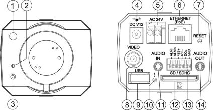
Figure 2.1 Front Panel and Rear Panel |
|
-- Front Panel -- |
-- Rear Panel -- |
1.Light Sensor: Registers the quality of light in the camera’s environment, and controls the iris shuttle to provide better information concerning the light.
2.MICROPHONE: The IP Camera has an additional audio function. The device has a microphone built into its front panel which records sound.
3.POWER indicator: Indicates the power status of the unit.
4.Plug Inlet: A DC 12V inlet that connects to an external power supply.
5.Plug Inlet: An AC 24V inlet that connects to an external power supply.
6.ETHERNET 10/100 Connector: This is a standard RJ-45 connector for 10/100 Mbps Ethernet networks. PoE (Power over Ethernet) function: Provides power to the device via the same cable as used for the network connection.
7.RESET: Recover to factory default. (Refer to section 2.5 The Reset Button.)
8.VIDEO OUT Connector: The connector provides the unit’s composite video signals to a monitor. (This connector adjusts and improves the images.)
9.USB port: The user can use a USB device cable to connect the IP camera to the USB port on the PC.
10.LED indicator: The green light indicates the unit is activating and the SD card cannot be removed.
11.AUDIO IN: The connector is used to connect the audio output from other devices to the camera.
12.SD/ SDHC CARD slot: This is used for updating system software and archiving / accessing critical images.
13.GPIO: This is a 6-PIN connector including the ALARM IN/OUT, RS-485, DC OUTPUT and GROUND items for connecting with external devices.
14.AUDIO OUT: Provides the camera’s audio signal to a speaker or stereo.
18 |
Installation and Operation Guide |

Installation and Operation Guide
Figure 2.2 Flank Panel:
|
|
IRIS |
|
|
|
1.ALM-OUT A |
7.RS-485:D+ |
1. AES |
1 |
3 |
|
2.ALM-OUT B |
8.RS-485:D- |
2. DC IRIS |
|
|
|
3.ALM-IN + |
9.DC-OUT(5V) |
|
|
||
|
2 |
4 |
|||
4.ALM-IN - |
10.GND |
3. DHCP |
|||
|
|
||||
5.ALM-RST + |
11.AUDIO-IN |
4. STATIC IP |
|
||
6.ALM-RST - |
12.AUDIO-OUT |
|
|||
|
|
|
|||
|
1 |
|
|
2 |
|
1. IRIS: Auto iris connector.
This camera works with a DC drive auto iris lens. Please refer to the pin assignment marked on the camera when connecting the auto iris lens
2. DIP Switch:
1.AES: Auto electric shutter.
2.DC IRIS: Use an auto iris (DC drive)
3. DHCP: Turn On / Turn Off to use the DHCP protocol. If the switch points upwards, the device can change the setup of network function (enable/disable) via the network.
4. STATIC IP: If the switch points down, the device can’t obtain an IP address from the DHCP server. This option is needed to configure the network communication settings.
(*In the default factory configuration, this DIP Switch is in the Down position.)
19
2.2 The Illustra 400 Fixed IP Indoor Mini-Dome (PoE)
Figure 2.3 Fixed IP indoor mini-dome
8
9
10
1 2 3 4 5 6 7
1.Plug Inlet: A DC 12V inlet that connects to an external power supply.
2.Plug Inlet: An AC 24V inlet that connects to an external power supply.
3.ETHERNET 10/100 Connector: This is a standard RJ-45 connector for 10/100 Mbps Ethernet networks. PoE (Power over Ethernet) function: Provides power to the device via the same cable as used for the network connection.
4.AUDIO IN: The connector is used to connect the audio output from other devices to the camera.
5.VIDEO OUT Connector: The connector provides the unit’s composite video signals to a monitor. (This connector adjusts and improves the images.)
6.AUDIO OUT: Provides the camera’s audio signal to a speaker or stereo.
7.GPIO: This is a 6-PIN connector including the ALARM IN/OUT, RS-485, DC OUTPUT and GROUND items for connecting with external devices.
8.USB port: The user can use a USB device cable to connect the IP camera to the USB port on the PC.
9.SD/ SDHC CARD slot: This is used for updating system software and archiving / accessing critical images.
10.RESET: Recover to factory default. (Refer to section 2.5 The Reset Button.)
20 |
Installation and Operation Guide |
Installation and Operation Guide
2.3 The Illustra 400 Fixed IP Outdoor Mini-Dome (PoE)
Figure 2.3 The IP Out-door mini-dome
8
9 |
10 |
1 2 3 4 5 6 7
1.Plug Inlet: A DC 12V inlet that connects to an external power supply.
2.Plug Inlet: An AC 24V inlet that connects to an external power supply.
3.ETHERNET 10/100 Connector: This is a standard RJ-45 connector for 10/100 Mbps Ethernet networks. PoE (Power over Ethernet) function: Provides power to the device via the same cable as used for the network connection.
4.AUDIO IN: The connector is used to connect the audio output from other devices to the camera.
5.VIDEO OUT Connector: The connector provides the unit’s composite video signals to a monitor. (This connector adjusts and improves the images.)
6.AUDIO OUT: Provides the camera’s audio signal to a speaker or stereo.
7.GPIO: This is a 6-PIN connector including the Digital output/input, DC output and GROUND items for connecting with external devices.
8.USB port: The user can use a USB device cable to connect the IP camera to the USB port on the PC.
9.SD/ SDHC CARD slot: This is used for updating system software and archiving / accessing critical images.
10.RESET: Recover to factory default. (Refer to section 2.5 The Reset Button.)
21

2.4 The Illustra 400 Bullet IP Camera Indoor/outdoor (PoE)
The component parts (the internal view).
Dismantle the bullet IP camera to see its different parts. The picture here shows you the internal component items making up the product.
SCREWS
SUN SHIELD
SD PCB
LENS FAN
REAR CASE
MIDDLE CASE
SENSOR PCB POWER PCB WATERPROOF RUBBER
PCB PLATE
IR PCB
FRONT CASE
Figure 2.5 The internal view of Bullet Camera Camera with bracket (the external view).
The picture here shows the camera's exterior, with the bracket screwed in and fixed to it. The bracket enables you to easily mount the camera on a wall, turned at the angle you want.
Figure 2.6 The external view of Bullet Camera
NOTE: Use the 2 screws to screw the sun shield (above) into the 2 extreme holes indicated in the bullet camera (below) to get an unobstructed viewing angle.
Please don’t use the middle hole in the camera, as that will block the view.
22 |
Installation and Operation Guide |

Installation and Operation Guide
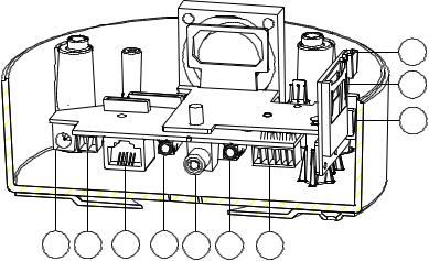
Figure 2.7 The PCB board
6 |
7 |
8 |
9 |
10 |
1 |
2 |
3 |
4 |
5 |
1.Plug Inlet: An AC 24V inlet that connects to an external power supply.
2.ETHERNET 10/100 Connector: This is a standard RJ-45 connector for 10/100 Mbps Ethernet networks. PoE (Power over Ethernet) function: Provides power to the device via the same cable as used for the network connection.
3.Plug Inlet: A DC 12V inlet that connects to an external power supply.
4.GPIO: This is a 6-PIN connector including the Digital output/input, DC output and
GROUND items for connecting with external devices.
5.VIDEO OUT Connector: The connector provides the unit’s composite video signals to a monitor. (This connector adjusts and improves the images.)
6.AUDIO IN: The connector is used to connect the audio output from other devices to the camera.
7.USB port: The user can use a USB device cable to connect the IP camera to the USB port on the PC.
8.AUDIO OUT: Provides the camera’s audio signal to a speaker or stereo.
9.SD/SDHC CARD slot: This is used for updating system software and archiving / accessing critical images.
10.RESET: Recover to factory default. (Refer to section 2.5 The Reset Button.)
23
2.5 The Reset Button
You can use the Reset button to reset the camera operations back to default. Press the Reset Button for about 10 seconds. Blue screens are displayed, and a text saying “RESETTING…” will appear. The device auto reboots. All settings have now reverted back to default. The following items return back to default.
[SETUP]
Network Setup
a.LAN Settings (You can manually reset this function by yourself.)
b.PPPOE Settings (You can manually reset this function by yourself.)
Dynamic DNS
a.DYNAMIC DNS SETTING (You can manually reset this function by yourself.)
IMAGE SETUP
a.Privacy Mask Setting
b.IMAGE SETTINGS
AUDIO AND VIDEO
a.VIDEO PROFILE 1
b.VIDEO PROFILE 2
c.VIDEO PROFILE 3
d.AUDIO SETTINGS
MOTION DECTION
a.Video Motion setting
TIME AND DATE
a.TIME CONFIGURATION
b.AUTOMATIC TIME CONFIGURATION
c.SET DATE AND TIME MANUALLY
Event Setup
a.Server
b.Media
c.Event
d.Recording
[ADVANCED]
DI and DO
a.DI and DO
b.LED
c.VIDEO OUTPUT
RS-485 (for the IP Box Camera only)
a.RS-485
ICR
a.ICR
HTTPS
a.HTTPS
Access List
a.Allow List
b.Deny List
24 |
Installation and Operation Guide |
Installation and Operation Guide
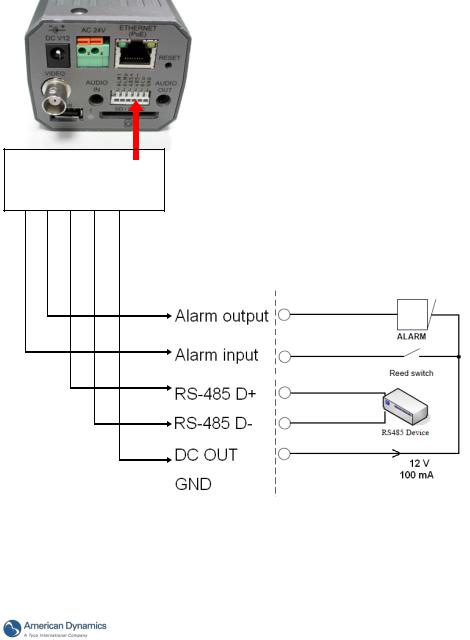
2.6 The Alarm wiring diagrams
Figure 2.8 Illustra 400 IP BOX CAMERA (PoE)
ALM i ALM o |
485 + |
485 - |
DC o |
GND |
|
|
|
|
|
+12V
+12V
25
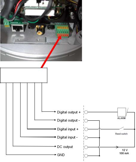
Figure 2.9 Illustra 400 Fixed IP Indoor/ Outdoor Mini-Dome (PoE)
GND 12V+ Di - Di + Do - Do +
+12V
+12V
26 |
Installation and Operation Guide |

Installation and Operation Guide
Figure 2.10 Illustra 400 Bullet IP Camera Indoor/outdoor (PoE)
GND 12V+ Di - Di + Do - Do +
+12V
+12V
27

2.7 The USB function
By connecting the IP camera with a PC via the USB connector, the IP camera can provide two
different functions.
1.Insert an SD card: As a card reader.
Insert an SD card into the IP camera, and then connect to the PC. You can transfer files between the SD card and the PC. Once you've connected your IP camera to your computer, the Windows system will detect the connection and ask you what you want to do with your SD card.
In other words, if you connect the IP camera with an SD card and the PC via the USB connector, the IP camera can be used as a normal card reader.
2.Remove an SD card: As a configuring tool.
Before using the USB configuration setting page, please remember to remove the SD card or your PC will read the SD card and won’t show this window.
DHCP ON
DHCP OFF
(default)
Network
Setting
Figure 2.11 The USB function
NOTE: After changing the settings, please click the “Apply” button. All of the options will
be effective after removing the USB connector.
NOTE: After the IP address has been changed and/ or reset, please unplug the network cable, and then plug it in once again to make sure the network connection is in normal mode.
28 |
Installation and Operation Guide |
Installation and Operation Guide
3. INSTALLATION
Please follow the instructions and the diagram below to set up the system.
NOTE: The IP camera is linked by its Video Out connection via a BNC connector to a monitor's Video In connection. If this connection is there, you can see some information on the monitor screen, such as the IP camera factory default Static IP address (192.168.1.168). But the IP camera Static IP address can only appear if there is a connection between the IP camera and another device. If there is no such connection, the IP camera factory default Static IP address will not appear on the monitor screen.
3.1 Hardware Installation
1.Plug in the power connection to the IP camera.
2.Plug in the IP camera cable.
3.Confirm the correct network connection status (PC/HUB/ IP camera).
4.In the PC IE Browser, key in the camera’s IP online to link up to the live first page.
NOTE: The red light power indicator on the IP Box Camera flashes when the power supply is on.
Two-color network indicator:
1.It is off when the network is disconnected.
2.The green light goes on when the network is connected; the orange light flashes indicate the network connection status.
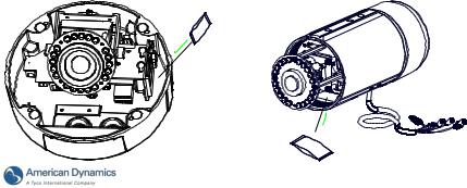
3.2Placing a Desiccant Pack Inside the Camera
The outdoor mini-dome/ bullet camera comes with a desiccant pack which is placed inside the camera using a two-sided adhesive tape. The desiccant pack is for reducing the moisture and humidity content inside the camera and prevents moisture from condensing on the lens or its cover. If the user decides to remove the camera cover after more than a few months of camera use, remove the used desiccant pack as well and place the replacement pack inside the camera.
1.Stick the piece of desiccant pack to the inner side of the camera.
2.Then use a two-sided adhesive tape to fix the desiccant pack.
3.Reattach the cover of the camera.
The Outdoor Mini-dome Camera: |
The Bullet Camera: |
29
3.3 Updating System Software
If the system software of the IP Camera needs to be upgraded, please take the following steps to safely process it.
Important: Before carrying out the following procedures, please ensure the SD card is working and the file of the system firmware is intact.
1.Create a directory named UPGRADE (upper-case or lower-case letters are no difference) in the SD card if it does not exist.
2.Copy the file UPDATE.BIN to the UPGRADE directory.
3.If the IP Camera is running, please power it off first.
4.Insert the SD CARD into the IP Camera.
5.Remove the Ethernet cable from the RJ-45 port and then power on the IP Camera.
6.In 5 to 10 seconds, a message reading "UPDATE PROCESSING" will show up on the screen on a blue background; if not, please check out steps 1 to 6 carefully or else inform your technical support while ignoring the following steps.
7.DO NOT power off the IP Camera while this update process is running until the message "UPDATE OK RESET PLEASE" appears on the screen; it might take 15 to 30 seconds to appear.
8.If the message "UPDATE NG RESET PLEASE" appears rather than "UPDATE OK RESET PLEASE", please write down the error messages shown on the screen and inform your technical support, while ignoring the following steps.
9.Power off the IP Camera when this update process is finished, then remove the SD card from the IP Camera.
10.Reconnect the Ethernet cable to the RJ-45 port if necessary.
11.Power ON the IP Camera and it will work normally if the entire update procedure goes correctly.
12.Verify the version of the system software.
WARNING:
You must perform Steps 1 to 2 on a PC.
Ensure you are using the correct UPDATE.BIN file in Step 2, otherwise the IP Camera will not work properly.
If the power of the IP Camera is suddenly lost in step 7, please remove the SD card first and turn on the IP Camera next to test its operation. If the IP Camera remains working normally, please go back to step 3; otherwise, please inform your technical support.
In step 9, if the SD card is not removed and the IP Camera does not get online as well, the updating process must be repeated again after rebooting the IP Camera.
Make sure that the SD card is inserted in a correct position in step 4, or the IP Camera will suffer permanent physical damage.
If the message "CSUM ERROR" appears in step 7, it implies a problem in the UPDATE.BIN file.
Do not interrupt the process when the unit is updating or it will crash.
30 |
Installation and Operation Guide |
Loading...