


 Loading...
Keyboard Operator’s Manual
AD2089
Part Number 8200-0710-01 B0
REV 1

Notice
The information in this manual was current when published. The manufacturer reserves the right to revise and improve its products. All specifications are therefore subject to change without notice.
Copyright
Under copyright laws, the contents of this manual may not be copied, photocopied, reproduced, translated or reduced to any electronic medium or machine-readable form, in whole or in part, without prior written consent of Sensormatic Electronics. © Copyright 1997-2005, Sensormatic Electronics Corporation.
American Dynamics
6795 Flanders Drive
San Diego, CA 92121-2903 U.S.A.
Customer Service
Thank you for using American Dynamics products. We support our products through an extensive worldwide network of dealers. The dealer through whom you originally purchased this product is your point of contact if you need service or support. Our dealers are empowered to provide the very best in customer service and support. Dealers should contact American Dynamics at (800) 507-6268 or (561) 912-6259 or on the Web at www.americandynamics.net.
Trademarks
Intellex® is a registered trademark of Sensormatic Electronics Corporation. IntelleCord™ and Smart Search™ are trademarks of Sensormatic Electronics Corporation. Windows® is a registered trademark of Microsoft Corporation. PS/2® is a registered trademark of International Business Machines Corporation. Sony® is a registered trademark of Sony Corporation.
Trademarked names are used throughout this manual. Rather than place a symbol at each occurrence, trademarked names are designated with initial capitalization. Inclusion or exclusion is not a judgment on the validity or legal status of the term.
ii

Warnings
WARNING: TO REDUCE RISK OF ELECTRIC SHOCK, DO NOT REMOVE COVER. NO USER SERVICEABLE PARTS INSIDE. REFER SERVICING TO QUALIFIED SERVICE PERSONNEL.
DO NOT EXPOSE THIS APPLIANCE TO RAIN OR MOISTURE.
DO NOT INSTALL THIS PRODUCT IN HAZARDOUS AREAS WHERE HIGHLY COMBUSTIBLE OR EXPLOSIVE PRODUCTS ARE STORED OR USED.
The lightning flash/arrowhead symbol, within an equilateral triangle, alerts the user to the presence of a shock hazard within the product’s enclosure.
CAUTION: Danger of explosion if battery is incorrectly replaced.
Replace only with the same or equivalent type recommended by the battery manufacturer. Dispose of used batteries according to the battery manufacturer’s instructions.
VORSICHT: ZUR VERMEIDUNG EINES STROMSCHLAGES DARF DAS GEHÄUSE NICHT ENTFERNT WERDEN. ES ENTHÄLT KEINE VOM BENUTZER ZU WARTENDEN TEILE. ÜBERLASSEN SIE DIE WARTUNG NUR QUALIFIZIERTEM FACHPERSONAL.
CAUTION: Es besteht die Gefahr einer Explosion, wenn die Batterie nicht ordnungsgemäß ausgetauscht wird.
WARNING: THIS EQUIPMENT IS A CLASS 1 LASER PRODUCT INCORPORATING A CLASS 1 LASER DIODE AND IT COMPLIES WITH FDA RADIATION PERFORMANCE STANDARDS, 21 CFR SUBCHAPTER J AND THE CANADIAN RADIATION EMITTING DEVICES ACT, REDR C1370.
Rack Mounting
Consult with the supplier of your equipment rack for adequate rack mounting means, with proper consideration for the weight of this product.
Consult with the manufacturer of your rack regarding the proper hardware and procedure of mounting this product in a safe and useable fashion
Avoid uneven loading or mechanical instability when rack-mounting units. Make sure that units are installed to get enough air flow for safe operation. The maximum temperature for rack-mounted units is 40° C.
Avoid uneven loading or mechanical instability when rack-mounting units.
Check product label for power supply requirements to assure that no overloading of supply circuits or overcurrent protection occurs. Mains grounding must be reliable and uncompromised by any connections.
WARNING: THIS EQUIPMENT HAS BEEN TESTED AND FOUND TO COMPLY WITH THE LIMITS FOR A CLASS “A” DIGITAL DEVICE, PURSUANT TO PART 15 OF THE FCC RULES. THESE LIMITS ARE DESIGNED TO PROVIDE REASONABLE PROTECTION AGAINST HARMFUL INTERFERENCE WHEN THE EQUIPMENT IS OPERATED IN A COMMERCIAL ENVIRONMENT. THIS EQUIPMENT GENERATES, USES AND CAN RADIATE RADIO FREQUENCY ENERGY AND, IF NOT INSTALLED AND USED IN ACCORDANCE WITH THE INSTRUCTION MANUAL, MAY CAUSE INTERFERENCE TO RADIO COMMUNICATIONS. OPERATION OF THIS EQUIPMENT IN A RESIDENTIAL AREA IS LIKELY TO CAUSE HARMFUL INTERFERENCE IN WHICH CASE THE USER WILL BE REQUIRED TO CORRECT THE INTERFERENCE AT THEIR OWN EXPENSE.
Changes or modifications not expressly approved by the party responsible for compliance could void the user’s authority to operate the equipment.
NOTE: This product was FCC verified under test conditions that included the use of shielded I/O cables and connectors between system components. To be in compliance with FCC regulations, the user must use shielded cables and connectors for all except power and alarm cables.
This digital apparatus does not exceed the Class A limits for radio noise emissions as set out in the Radio Interference Regulations (ICES-003) of the Canadian Department of Communications.
iii

License Information
READ THIS LICENSE AGREEMENT BEFORE OPENING THE DISK PACKAGE, INSTALLING THE SOFTWARE, OR USING YOUR SYSTEM.
THIS LICENSE AGREEMENT DEFINES YOUR RIGHTS AND OBLIGATIONS. BY BREAKING THE SEAL ON THIS PACKAGE, INSTALLING THE SOFTWARE, OR USING YOUR SYSTEM, YOU AGREE TO ALL OF THE TERMS AND CONDITIONS OF THIS AGREEMENT. IF YOU DO NOT AGREE TO ALL OF THE TERMS AND CONDITIONS OF THIS AGREEMENT, YOU MAY, WITHIN 30 DAYS, RETURN THIS PACKAGE, ALL THE DOCUMENTATION, AND ALL ACCOMPANYING MATERIAL(S) TO THE POINT OF PURCHASE FOR A REFUND.
SOFTWARE LICENSE
The software includes the Intellex API, modular programs and source codes provided as samples, the Intellex API manual and any electronic documentation; and is provided to you by installing the software on a computer hard drive. The software is licensed, not sold.
GRANT OF LICENSE
The purchase of Intellex API software constitutes a license agreement between Sensormatic and you. This license agreement permits you and only you to use the software. By purchasing the Intellex API license agreement, you may use the API software and accompanying modular programs with their source codes. This license agreement does not grant you the right to resell nor distribute the API nor the modular programs and their source codes or additional copies of them to another entity. The software is only licensed for use with Intellex equipment. There are no restrictions on instituting a licensing program internal to your organization with regard to the software products that you develop using the API; however, no software programs that you develop using the Intellex API or the modular programs can be sold nor distributed by you to other entities as accessory products for Intellex product line without authorization from Sensormatic.
OTHER RIGHTS AND LIMITATIONS
•A demonstration copy of the Software is considered purchased and is covered by this license agreement.
•The purchase order is your proof of license to exercise the rights granted herein and must be retained by you.
•You may not de-compile, disassemble, or reverse engineer any of the executables; including, but not limited to the library files, for which you were not given the source code. The modular programs are excluded from this restriction and you may re-compile, reassemble, or alter any component of the source codes that are provided to you.
•You may not sub-license, rent or lease the software; nor permanently transfer the software to another party by delivering the original media material comprising the software package as well as this license to the other party.
•Sensormatic reserves the right to revoke this agreement if you fail to comply with the terms and conditions of this agreement. In such an event, you must destroy all the Intellex API software on and/or loaded from the purchased CD ROM, any API software downloaded from the web or sent on “patch” media, all of the modular programs you modified and all the software programs that you developed using the Intellex API.
•The software may contain software from third parties that is licensed under a separate End User License Agreement (EULA). Read and retain any license documentation that may be included with the Software. Compliance with the terms of any third party EULA is required as a condition of this agreement.
Failure to comply with these restrictions will result in automatic termination of this license and will make available to Sensormatic other legal remedies.
COPYRIGHT
The software is a proprietary product of Sensormatic and is protected by both the United States and International copyright laws.
UPGRADES
If the software is an upgrade from another software version, or an upgrade of a component of a package of software programs that you licensed you may use or transfer the software only as specified in this agreement.
LIMITED WARRANTY
Sensormatic warrants that the recording medium on which the software is recorded, and the documentation provided with it, will be free of defects in materials and workmanship under normal use for a period of ninety (90) days from the date of delivery to the first user. Sensormatic further warrants that for the same period, the software provided on the recording medium under this license will substantially perform as described in the user documentation provided with the product when used with the specified hardware and development environment.
CUSTOMER REMEDIES
Sensormatic’s entire liability and your exclusive remedy under this warranty will be, at Sensormatic’s option, to a). attempt to correct software errors with efforts we believe suitable to the problem, b). replace at no cost the recording medium, software or documentation with functional equivalents as applicable, or c). refund the license fee and terminate this agreement. Any replacement item will be warranted for the remainder of the original warranty period. No remedy is provided for failure of the diskette or Software if such failure is the result of accident, abuse, alteration or misapplication. Warranty service or assistance is provided at the original point of purchase.
NO OTHER WARRANTIES
The above warranty is in lieu of all other warranties, express or implied, including, but not limited to the implied warranties of merchantability and fitness for a particular purpose. No oral or written information or advice given by Sensormatic, its representatives, distributors or dealers shall create any other warranty, and you may not rely on such information or advice.
NO LIABILITY FOR CONSEQUENTIAL DAMAGES
In no event will Sensormatic be liable to you for damages, including any loss of profits, loss of data or other incidental or consequential damages arising out of your use of, or inability to use, the Software or its documentation. This limitation will apply even
iv

Contents
Contents
AD2089 Keyboard Controller
About the AD2089 Keyboard Controller. . . . . . . . . . . . . . . . . . . . . . . . . . . . . . . . . . . .1
AD2089 Features . . . . . . . . . . . . . . . . . . . . . . . . . . . . . . . . . . . . . . . . . . . . . . . . . .1
AD2089 Keyboard Overview . . . . . . . . . . . . . . . . . . . . . . . . . . . . . . . . . . . . . . . . . .2
Connection and Setup of the AD2089
Supplied Equipment. . . . . . . . . . . . . . . . . . . . . . . . . . . . . . . . . . . . . . . . . . . . . . .4 Connecting to a Switching System . . . . . . . . . . . . . . . . . . . . . . . . . . . . . . . . . . .4 Connections for Cable Distance of Seven Feet or Less . . . . . . . . . . . . . . . . . . .5 Connections for Cable Distance of Greater than Seven Feet . . . . . . . . . . . . . . .5 Power Connections . . . . . . . . . . . . . . . . . . . . . . . . . . . . . . . . . . . . . . . . . . . . . . .5 Installation Precautions . . . . . . . . . . . . . . . . . . . . . . . . . . . . . . . . . . . . . . . . . . . .6
Keyboard Setup. . . . . . . . . . . . . . . . . . . . . . . . . . . . . . . . . . . . . . . . . . . . . . . . . . . .7 Setting Keyboard Parameters . . . . . . . . . . . . . . . . . . . . . . . . . . . . . . . . . . . . . . .7 Built-in Keyboard Operations Test . . . . . . . . . . . . . . . . . . . . . . . . . . . . . . . . . . . . .9
Using the AD2089 in Operate Mode
User Numbers and Passcodes . . . . . . . . . . . . . . . . . . . . . . . . . . . . . . . . . . . . .14 Monitor Mode Operations (keyswitch in “operate” position) . . . . . . . . . . . . . . . . .15 Selecting Monitors . . . . . . . . . . . . . . . . . . . . . . . . . . . . . . . . . . . . . . . . . . . . . . .15 Calling a Camera to View on a Monitor . . . . . . . . . . . . . . . . . . . . . . . . . . . . . . .15 Controlling a Camera's Pan and Tilt . . . . . . . . . . . . . . . . . . . . . . . . . . . . . . . . .15 Locking and Unlocking a Camera . . . . . . . . . . . . . . . . . . . . . . . . . . . . . . . . . . .16 Controlling Camera Zoom . . . . . . . . . . . . . . . . . . . . . . . . . . . . . . . . . . . . . . . . .16 Controlling Camera Focus . . . . . . . . . . . . . . . . . . . . . . . . . . . . . . . . . . . . . . . . .16 Controlling the Camera Iris . . . . . . . . . . . . . . . . . . . . . . . . . . . . . . . . . . . . . . . .16 Controlling Camera Flip . . . . . . . . . . . . . . . . . . . . . . . . . . . . . . . . . . . . . . . . . . .17 Auto Focus / Auto Iris. . . . . . . . . . . . . . . . . . . . . . . . . . . . . . . . . . . . . . . . . . . . .17 Calling Presets (Shots) . . . . . . . . . . . . . . . . . . . . . . . . . . . . . . . . . . . . . . . . . . .17 Running System Tours . . . . . . . . . . . . . . . . . . . . . . . . . . . . . . . . . . . . . . . . . . .17 Holding a Tour . . . . . . . . . . . . . . . . . . . . . . . . . . . . . . . . . . . . . . . . . . . . . . . . . .18 Re-Starting a Tour on Hold . . . . . . . . . . . . . . . . . . . . . . . . . . . . . . . . . . . . . . . .18 Changing Tour Direction . . . . . . . . . . . . . . . . . . . . . . . . . . . . . . . . . . . . . . . . . .18 Calling Salvos . . . . . . . . . . . . . . . . . . . . . . . . . . . . . . . . . . . . . . . . . . . . . . . . . .18 Auxiliary Control. . . . . . . . . . . . . . . . . . . . . . . . . . . . . . . . . . . . . . . . . . . . . . . . .18 Acknowledging Alarms. . . . . . . . . . . . . . . . . . . . . . . . . . . . . . . . . . . . . . . . . . . .19 Viewing Satellite Sites . . . . . . . . . . . . . . . . . . . . . . . . . . . . . . . . . . . . . . . . . . . .19 Running Patterns . . . . . . . . . . . . . . . . . . . . . . . . . . . . . . . . . . . . . . . . . . . . . . . .19 Running a Macro . . . . . . . . . . . . . . . . . . . . . . . . . . . . . . . . . . . . . . . . . . . . . . . .20
User’s Guide vii

Contents
Playback Mode Operations (keyswitch in operate position) . . . . . . . . . . . . . . . . .21 Selecting DVRs . . . . . . . . . . . . . . . . . . . . . . . . . . . . . . . . . . . . . . . . . . . . . . . . .21
Programming with the AD2089
Using the AD2089 in Program Mode. . . . . . . . . . . . . . . . . . . . . . . . . . . . . . . . . . .22
Setting Presets. . . . . . . . . . . . . . . . . . . . . . . . . . . . . . . . . . . . . . . . . . . . . . . . . .22
Setting Scratch Pad Tours . . . . . . . . . . . . . . . . . . . . . . . . . . . . . . . . . . . . . . . . .22
Programming Patterns . . . . . . . . . . . . . . . . . . . . . . . . . . . . . . . . . . . . . . . . . . . .22
Defining Patterns . . . . . . . . . . . . . . . . . . . . . . . . . . . . . . . . . . . . . . . . . . . . . . . .23
Clearing Patterns . . . . . . . . . . . . . . . . . . . . . . . . . . . . . . . . . . . . . . . . . . . . . . . .23
Arming a Monitor . . . . . . . . . . . . . . . . . . . . . . . . . . . . . . . . . . . . . . . . . . . . . . . .23
Disarming a Monitor. . . . . . . . . . . . . . . . . . . . . . . . . . . . . . . . . . . . . . . . . . . . . .23
Programming Macros. . . . . . . . . . . . . . . . . . . . . . . . . . . . . . . . . . . . . . . . . . . . .24
Deleting Macros . . . . . . . . . . . . . . . . . . . . . . . . . . . . . . . . . . . . . . . . . . . . . . . . .26
Using the AD2089 in Menu Mode . . . . . . . . . . . . . . . . . . . . . . . . . . . . . . . . . . . . . . .27
Specifications |
29 |
Troubleshooting |
30 |
Typical System Connections |
31 |
AD2089 Keyboards to AD1024 System with Network Client/DVMS Control . . . .31 AD2089 Keyboard to AD1024 CPU . . . . . . . . . . . . . . . . . . . . . . . . . . . . . . . . . . .32 AD2089 Keyboard to AD1024 CPU . . . . . . . . . . . . . . . . . . . . . . . . . . . . . . . . . . .33 AD2089 Keyboard to AD2150 . . . . . . . . . . . . . . . . . . . . . . . . . . . . . . . . . . . . . . . .34 AD2089 Keyboard to AD2150 . . . . . . . . . . . . . . . . . . . . . . . . . . . . . . . . . . . . . . . .35 AD2089 Keyboard to AD168 . . . . . . . . . . . . . . . . . . . . . . . . . . . . . . . . . . . . . . . . .36 AD2089 Keyboard to AD168 . . . . . . . . . . . . . . . . . . . . . . . . . . . . . . . . . . . . . . . . .37 AD2089 to MegaPower 48 . . . . . . . . . . . . . . . . . . . . . . . . . . . . . . . . . . . . . . . . . .38 Built-in Test Connection . . . . . . . . . . . . . . . . . . . . . . . . . . . . . . . . . . . . . . . . . . . .39
Software License Agreement |
40 |
Monitor Arming Commands |
43 |
viii |
Intellex® Digital Video Management System |

Contents
Macro Key Labels
Macro Programming Worksheets
Macro Programming Workskeet . . . . . . . . . . . . . . . . . . . . . . . . . . . . . . . . . . . . . .48
User’s Guide ix

Contents
x |
Intellex® Digital Video Management System |

AD2089 Keyboard Controller
About the AD2089 Keyboard Controller
This chapter describes the features of the AD2089 keyboard. It also describes the location and function of the keyboard's front panel components.
AD2089 Features
The AD2089 video control station is fully compatible with the American Dynamics MegaPower CPU and MegaPower 1024 when used in conjunction with Network Client 4.04 (or later) and Intellex DVMS or Ultra digital video recorders.
Note
In addition to controlling the matrix switchers through Network Client, the AD2089 will work directly with the MegaPower 48, MegaPower 168, and MegaPower 1024 matrix switcher/controller systems but will not support the AD2089 DVMS functions.
The AD2089 enables the user to view and control cameras and video recorders at local and remote facilities, and to control auxiliary devices such as door locks and lights. Additionally, the operator can acknowledge alarms with the unit. The aforementioned functions are accomplished in the keyboard’s Operate Mode. Operators with key privileges can also perform programming functions with the AD2089. These functions include programming of presets (targets), patterns, scratchpad tours, and macros. Macros are user programmed functions made up of as many as 21 keystrokes that are executed with a single keystroke. Operators can also arm and disarm monitors for display of system alarms. These functions are accomplished in the Program Mode. Menu programming enables operators to set up the parameters of American Dynamics switching systems. System setup is accomplished in the Menu Mode.
A summary listing of AD2089 features follows:
•site ID - selects a site for satellite switching
•monitor/camera selection - provides selection for viewing and control
•pan/tilt and lens control - pan, tilt, and zoom control through joystick positioning. Focus and iris adjustments through lens control keys
•video recorder control and operation – enables selection of video recorders and execution of the following functions: Play, Stop, Fast-Forward, Rewind, Record, Pause, and Eject
•macro key programming and operation – up to 1000 macros divided among eight macro keys enable multi-step operation with a single keystroke
•joystick “Flip” push-button - enables user to flip cameras 180≡ from established position
•tour functions - enables programming, running, and control of camera sequences
•salvo functions - enables programming and simultaneous callup of multiple camera scenes
•alarm functions - supports monitor alarm arming, disarming, and alarm acknowledgment
•pattern and preset functions - enables programming and display of patterns and presets (shots)
•selectable baud rate - 1200, 2400, 4800, 9600, 19,200, 38,400 bps (1200 default)
•selectable LED brightness - enables eight different brightness levels
1

AD2089 Keyboard Controller
•selectable speaker volume - enables eight different volume levels
•auto focus/auto iris capability - supported when used with DeltaDome units
AD2089 Keyboard Overview
The AD2089 keyboard is comprised of the following elements:
ASite - shows the number of the site entered with the keypad when the SITE key (Sk) is pressed.
BMonitor/DVMS - shows the number of the monitor or DVR entered when the MON (Mk) or DVMS key is pressed.
CCamera - shows the number of the camera entered with the keypad when the CAM key (Ck) is pressed.
DEnter - shows the number entered on the NUMERIC KEYPAD (E).
ENumeric Keypad - has keys ranging from 0 - 9 that enable the user to select specific cameras, monitors, salvos, tours, presets, patterns, auxiliaries, recorders, sites and macros.
1Keyswitch - enables the user to switch the Operate, Program or Menu modes of operation.
When the keyswitch is set to Menu position, the page and cursor navigation functions of the multi-function keys are activated.
2Joystick - enables the user to pan, tilt, zoom and flip the camera under keyboard control.
3PROG key - enables the user to set scratch-pad tours and patterns, as well as a number of other switching system functions.
4F1 & F2 keys - special functions keys used to implement basic system commands and DeltaDome control F1 & F2 keys - special functions keys used to implement basic system commands and DeltaDome control
5LAST key - calls the prior camera displayed in a sequence (tour).
6NEXT key - calls the next camera displayed in a sequence (tour).
7HOLD key - Holds the current camera in a sequence (tour).
8SALVO key - calls a specified salvo whose number is entered on the numeric keypad.
9CLEAR key - clears data entered on the numeric keypad
10RUN key - runs system and scratch pad tours.
11MACRO keys – Each of the eight macro keys calls a specified macro whose number is entered on the numeric keypad.
2 |
AD2089 Operator’s Manual |
AD2089 Keyboard Controller
Multi-Function Keys
12 OFF/Page Left key/ Stop - turns off auxiliary device in Monitor Operate mode. Displays page to the left in Menu mode. In Playback Operate mode, DATE allows you to select a specific date for playback. On the Numbers Keypad, enter a 4-digit date (mmdd) and press DATE. As a shortcut, you can enter a 2-digit date (dd).
13 ON/Page Right key/ Record - turns on auxillary device in Monitor Operate mode. Displays place to the right in Menu mode. In Playback Operate mode, TIME allows you to select a specific time for playback. Once you have selected a date, enter a 4-digit time (hhmm), press TIME and then press PLAY. As a shortcut, you can enter a 2-digit time (hh).
14 CLOSE/Page Up key/ Pause - closes iris in Monitor Operate mode. Displays prior page up in Menu mode. Stops playing recorded video and resumes live video in Playback Operate mode.
15 OPEN/Page Down key/ Play - Opens iris in Monitor Operate mode. Displays prior page down in Menu mode. Saves a downloaded clip to a preconfigured database in Playback Operate mode.
16 NEAR/Left Arrow key/ Rewind - adjusts focus of near objects in Monitor Operate mode. Moves cursor left one character in Menu mode. Rewinds video at fast speed in Playback Operate mode. Each time button is pressed, video speed increases (up to 5x).
17 FAR/Right Arrow / Fast Forward key - adjusts focus of far objects in Monitor Operate mode. Moves cursor right one character in Menu mode. Plays video at fast speed in Playback Operate mode. Each time button is pressed, video speed increases (up to 5x). If play is paused, pressing this button will skip video forward one frame.
18 DVMS/Up Arrow/Play key – enables selection of Playback Operate mode. Initiates playback of a selected camera or of a camera that is already displayed on a selected monitor. Pressing the play button will put the keyboard into Playback Shifted mode. If playback is already in progress but has been paused, pressing the play button will resume playback. If playback is in progress and is still playing, the duration of playback is increased by one play-back interval and is re-downloaded.
19ACK key /Down Arrow /Eject Key- acknowledges alarms, runs tours, sets and repeats alarms. Pauses an image in Playback Operate mode.
20PRESET/Enter key - calls presets in Operate mode. Sets presets in Program mode. Stores entered menu data.
21PATRN/Exit key - runs and repeats patterns in Operate mode. Sets patterns in Program mode. Exits Menu mode.
3

Connection and Setup of the AD2089
Connection and Setup of the AD2089
This chapter describes the power and data connections between the AD2089 keyboard and the switching system being used. It also describes the setup of communications protocols and other keyboard parameters. Additionally, it describes built-in test procedures used to verify the operational integrity of the keyboard.
Supplied Equipment
The AD2089 is supplied with the following equipment and accessories:
•Wall Transformer (specified for national and local electrical requirements)
•One dual eight pin, wall-mount terminal block, with three jumper wires
•One single eight pin, wall-mount terminal block
•Two seven foot, eight conductor modular cables
•Eight clear key caps and four white key caps for the AD2089 macro key section
•Pre-printed macro key labels
•One extractor tool for macro key removal
The transformer is connected from the wall to the terminal block. Power is then routed through the dual terminal block to the keyboard's eight pin RJ-45 port via the seven foot cable.
Connecting to a Switching System
The dual terminal block consists of two single eight-screw terminal blocks located on the left and right sides of the block interior (see illustration below). Each of the eight terminal screws in a connector set are routed to an RJ-45 connector at the bottom of the block.
The J1 connector is connected to the AD2089 keyboard via one of the seven foot modular cables. The J2 connector is connected to the switching system via the other seven foot modular cable. Additional information showing typical system connections is included in Appendix C of this manual. Pin definitions for both the keyboard (J1) and system (J2) sides of the terminal block are listed in the table below
|
Screw |
|
Function |
|
1 |
|
Transformer Power In (J1 Only) |
|
|
|
|
|
2 |
|
Shield |
|
|
|
|
|
3 |
|
Not Used |
|
|
|
|
|
4 |
|
RS-232 RCD |
|
|
|
|
|
5 |
|
RS-232 XMIT |
|
|
|
|
|
6 |
|
Not Used |
|
|
|
|
|
7 |
|
Ground |
|
|
|
|
|
8 |
|
Transformer Power In (J1 Only) |
|
|
|
|
Dual Terminal Block |
|
|
Power and Data Connections Only |
|
|
Not for Connection to Telephone Lines |
|
|
|
|
|
|
|
|
|
|
|
Dual Terminal Block Screw Designations |
|
|
|
|
|
4 |
AD2089 Operator’s Manual |

Connection and Setup of the AD2089
Connections for Cable Distance of Seven Feet or Less
For switching system connections where keyboard-to-system cable distance is seven feet or less, make the following connections using the jumpers included with the dual terminal block
J1 Pins |
|
J2 Pins |
4 (rcd) |
5 |
(xmit) |
|
|
|
5 (xmit) |
4 |
(rcd) |
|
|
|
7 (ground) |
7 |
(ground) |
|
|
|
After connecting the jumpers, connect one of the seven foot modular cables from the J2 (system) jack of the dual terminal block, to the appropriate RS-232 port on the switching system. Connect the other seven foot modular cable from the J1(keyboard) jack of the dual terminal block, to the RJ-45 jack of the keyboard.
Connections for Cable Distance of Greater than Seven Feet
For switching system connections where keyboard-to-system cable distance is greater than seven feet, the following components are required.
•Dual terminal block supplied with the AD2089
•A three-wire, shielded, 18 AWG cable supplied by the installer
•Single terminal block supplied with the AD2089
Use the three-wire cable to connect the keyboard and switching system terminal blocks. The following table provides the connection points
Dual Block (J1 Side) Screws |
|
Single Block Screws |
4 (rcd) |
5 |
(xmit) |
|
|
|
5 (xmit) |
4 |
(rcd) |
|
|
|
7 (ground) |
7 |
(ground) |
|
|
|
The cable shield connects to Pin 2 of the single terminal block
After connecting the three-wire cable to the respective terminal blocks, connect one of the seven foot modular cables supplied with the AD2089 from the J1(keyboard) jack of the dual terminal block to the RJ-45 jack of the keyboard. Connect the other seven foot modular cable from the RJ45 jack of the single terminal block to the appropriate RS-232 port on the switching system.
Power Connections
Depending on national and local electrical requirements, the AD2089 is supplied with either a 120 VAC or a 230 VAC transformer. The 230 VAC transformer is supplied with a Euro-style IEC 320 type inlet. An appropriate detachable cord should be connected between the IEC 320 inlet and the power source.
Connect the output leads from the wall transformer to screws 1 and 8 on the J1(keyboard) side of the dual terminal block. All power to the AD2089 is supplied from this connection.
CAUTION!
DO NOT INSERT THE WALL TRANSFORMER
INTO THE POWER SOURCE UNTIL ALL
CONNECTIONS HAVE BEEN VERIFIED
Note
Typical system and test connections are illustrated in Appendix C of this manual.
5

Connection and Setup of the AD2089
Installation Precautions
The keyboard unit is susceptible to high electrostatic discharge potentials. Care should be taken to locate the unit so as to reduce the likelihood of accidental contact with ESD potentials, such as walking on a carpet under very dry conditions.
Should accidental contact occur, and the keyboard unit experiences loss of camera control, momentarily remove power to the unit. This will re-establish communication with the connected unit or system, and reset the camera status.
This installation should be made by qualified service personnel, and should conform to all local electrical codes. Safeguards must be taken to avoid unintentional operation by employees and maintenance personnel working about the premises, by falling objects, by customers, by building vibration, and by similar causes.
6 |
AD2089 Operator’s Manual |

Connection and Setup of the AD2089
Keyboard Setup
The AD2089 keyboard communicates via RS-232 protocol. Keyboard setup up the keyboard involves setting the keyboard's baud rate, LED brightness, speaker volume, and PTZ motion control.
Setting Keyboard Parameters
The operator can set the following four keyboard parameters:
•Baud Rate – 1200 (default), 2400, 4800, 9600, 19,200, and 38,400 bps
•LED Brightness - eight brightness levels
•Speaker Volume - eight volume levels
•Pan/Tilt/Zoom Motor Control – two control options can be set automatically or manually
To Enter Setup Mode
1Turn the three-position keyswitch to the MENU position.
2Press the F1 key. "SETUP BAUD =" appears in the CAMERA display. The current value of the baud rate appears in the ENTER display.
To Change the Baud Rate
1Press the NEXT key to cycle through the available baud rate settings in the forward direction: 1200, 2400, 4800, 9600, 19,200, and 38,400. Press the LAST key to cycle through in the reverse direction. The factory default setting is 1200 baud.
2When the appropriate baud rate appears in the display, press the PROG key to save the selection. You now have the option to either set the brightness level using the following procedure, or exit setup mode by pressing the F1 key, turning the keyswitch to OPERATE, MENU, and then back to OPERATE again.
To Set the Brightness Level
1After baud rate selection has been completed, the message "LEDS =" appears in the CAMERA display. The brightness level (an integer from 1 to 8) appears in the ENTER display. The integer 1 signifies minimum brightness. The integer 8 signifies maximum brightness. 8 is the factory default setting.
2To change the currently displayed brightness level, cycle through the levels using the NEXT or LAST keys to move in forward or reverse direction respectively. Each time the level changes, the intensity of the displayed characters changes as well.
3When the appropriate integer appears in the ENTER display, press the PROG key to save the selection. You now have the option to either set the speaker volume level using the following procedure, or exit setup mode by pressing the F1 key, turning the keyswitch to OPERATE, MENU, and then back to OPERATE again.
To Set the Speaker Volume
1After LED brightness level selection has been completed, the message "SOUND" appears in the CAMERA display. The speaker volume level ("Off" or integer values from 1 to 7) appears in the ENTER display. "Off" indicates the speaker is disabled. The integer 1 signifies the minimum volume level. The integer 7 signifies the maximum volume level. 7 is the factory default setting.
7

Connection and Setup of the AD2089
2To change the currently displayed volume level, cycle through the levels using the NEXT or LAST keys to move in forward or reverse direction respectively. Each time the level changes, a short tone sounds indicating the new level.
3When the appropriate level appears in the ENTER display, press the PROG key to save the selection. You now have the option to either set the PTZ motion control option using the following procedure, or exit the setup mode by pressing the F1 key, turning the keyswitch to OPERATE, MENU, and then back to OPERATE again.
To Set the Pan / Tilt / Zoom Motion Control Option
Depending on the particular switching system that is used with the AD2089 keyboard, the pan, tilt, and zoom (PTZ) motions of the system cameras are controlled by one of two methods: Repeat or Make/Break. Detailed descriptions of these two methods are beyond the scope of this manual, but a system administrator will be advised of the appropriate method to use, and will make the appropriate setting accordingly.
1After speaker volume level selection has been completed, the letters "rpt =" appear in the CAMERA display. "AUTO" will appear in the ENTER display. “AUTO” indicates that the switching system being used will automatically select either the Repeat or Make/Break control method.
2You can step through the “AUTO”, "OFF" and "ON" states by using the NEXT or LAST keys. If "OFF" is displayed, the Repeat method will be set off . If "ON" is displayed the Repeat method will be set on. The AD168 system operates with Repeat set to OFF. American Dynamics systems that operate with Repeat set to ON include AD1650B, AD1024, AD2052, AD2150, and AD2350. Consult with your system administrator about the appropriate setting for your system.
3When the appropriate state appears in the ENTER display, press the PROG key to save the selection. You now have the option to either set the baud rate using the procedure indicated on page 2-3, or exit the setup mode by pressing the F1 key, turning the keyswitch to OPERATE, MENU, and then back to OPERATE again.
Resetting Keyboard Parameters
1To reset baud rate, LED brightness level, speaker volume level, and the PTZ motion control option to factory default settings, first unplug the keyboard's wall transformer.
2Press and hold the F1 and PROG keys simultaneously while plugging the transformer back in.
8 |
AD2089 Operator’s Manual |
Connection and Setup of the AD2089
Built-in Keyboard Operations Test
CAUTION !
The following procedures expose internal electrical components and should be performed by qualified service personnel only.
The AD2089 has built-in test capability to verify the operational integrity of the unit's hardware and firmware. Built-in test functions include the following:
•speaker test
•LED lamp test
•LED brightness test
•LED seven segment test
•joystick calibration / speed test
•key functionality test
•keyswitch test
•serial communications test
•ROM checksum test
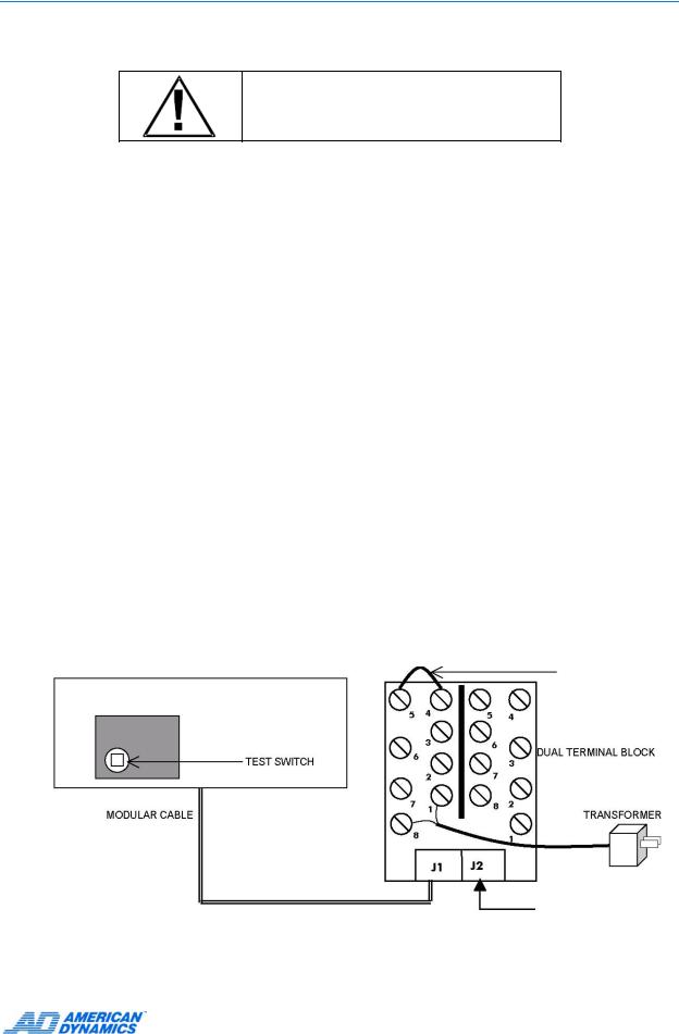
Procedure to Initiate Built-In Test
1Unplug the keyboard's wall transformer.
2Disconnect the matrix switching system's modular cable from the dual terminal block (J2).
3Connect a jumper wire to pins 4 and 5 on the J1 side of the dual terminal block.
4Detach the bottom plate of the keyboard by removing the four screws.
5Press and hold down the button labeled "test switch", while simultaneously plugging in the wall transformer.
AD2089 Keyboard
Underside
XMIT/RCD SELF-TEST JUMPER CONNECTION
DO NOT CONNECT TO
SYSTEM DURING
BUILT-IN-TEST
Each test is performed in sequence. Press the test switch button to advance to the next test procedure. To quit the test sequence, unplug and then re-plug the wall transformer
9

Connection and Setup of the AD2089
Speaker Test
The speaker test performs an audible check of the keyboard's speaker. A series of audio tones step through the frequency range of the speaker. During this test the CAMERA display shows the message "SOUND". The speaker test is repeated automatically, until the test switch button is pressed to advance to the LED lamp test.
LED Lamp Test
The LED lamp test simultaneously illuminates all segments of all LEDs in the four keyboard display sections. Press the test switch button to advance to the LED brightness test.
LED Brightness Test
In this test, all LEDs are stepped through the eight levels of intensity. The eight step sequence repeats continuously until the test switch button is pressed to advance to the seven segment LED test.
Seven Segment LED Test
This test simultaneously illuminates one of the seven segments for all 18 of the display LEDs for a brief interval. The next segment then illuminates, and then the next, and so on. The seven segment illumination cycle repeats continuously until the test switch button is pressed to advance to the joystick calibration / speed test.
Joystick Calibration / Speed Test
This test checks the joystick’s calibration, speed, and position. Codes representing these parameters appear in the keyboard’s ENTER, CAMERA, and MONITOR/DVMS displays.
When the joystick is in the center or “hands-free” position, dash marks appear in the ENTER display. The number “128” appears once in the MONITOR/DVMS display, and twice in the CAMERA display.
|
SITE |
|
|
|
|
MONITOR |
|
|
|
|
|
CAMERA |
|
|
ENTER |
||||||||||||
|
|
|
|
|
|
- |
- |
1 |
2 |
8 |
|
|
|
|
1 |
2 |
8 |
1 |
2 |
8 |
|
|
- |
|
- |
|
|
The dashes in the ENTER display indicate that no pan or tilt commands are being transmitted. “128” in the MONITOR/DVMS display indicates that the joystick is not being twisted in a clockwise or counter-clockwise direction. Twisting clockwise zooms in. Twisting counter-clockwise zooms out.
The left-most “128” in the CAMERA display indicates the hands-free position for panning. The right-most “128” indicates the hands-free position for tilting.
Note
Due to variations in components and voltage sources, the center and endpoint numeric values for each keyboard may vary by small amounts.
If the dashes are not displayed when the joystick is physically centered (when the operator releases the joystick), then the joystick is not properly calibrated. Contact American Dynamics Technical Support Center at 1-800-442-2225.
When the joystick is moved in any direction away from the center position, the dashes in the ENTER display are replaced by a four-digit movement code:
10 |
AD2089 Operator’s Manual |
Loading...