


 Loading...
American Dynamics ADSDU8E22I2X2N, ADSDU8E22I2X2P, ADSDU8E22I2X2SN, ADSDU8E22I2X2SP, ADSDU8E22IHN Installation
...SpeedDome Ultra 8
Camera Dome
Installation and Service Guide
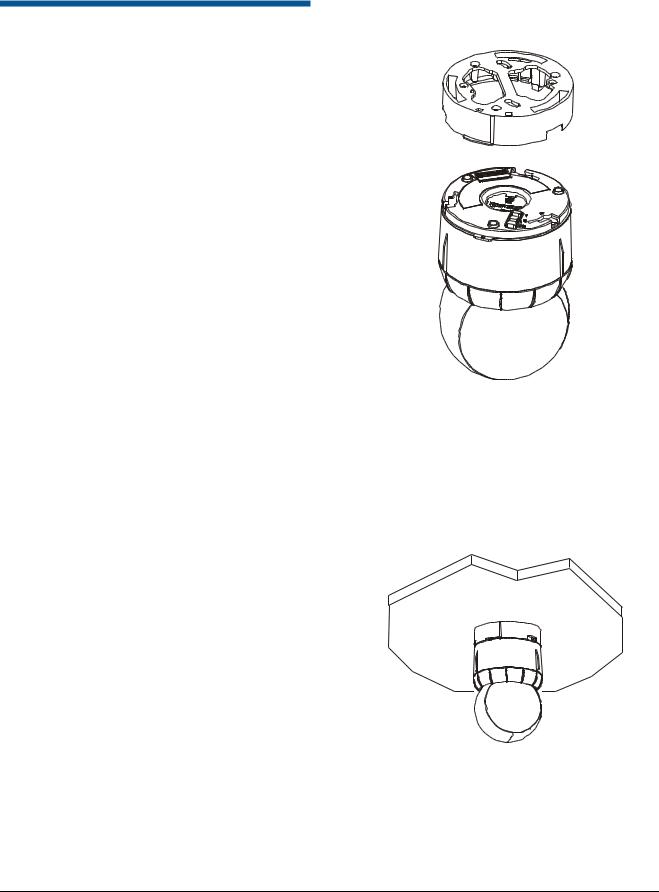
Figure 1. SpeedDome Ultra Camera Dome
Mounting
Base
Housing
Eyeball 
Camera Dome Product Codes
Product |
Description |
ADSDU822N |
22X, N, VERSION 1.00, BLACK |
ADSDU822P |
22X, P, VERSION 1.00, BLACK |
|
|
ADSDU822WN |
22X, N, VERSION 1.00, WHITE |
|
|
ADSDU822WP |
22X, P, VERSION 1.00, WHITE |
|
|
ADSDU835N |
35X, N, DAY/NIGHT, VERSION 1.00, BLACK |
|
|
ADSDU835P |
35X, P, DAY/NIGHT, VERSION 1.00, BLACK |
|
|
ADSDU835WN |
35X, N, DAY/NIGHT, VERSION 1.00, WHITE |
|
|
ADSDU835WP |
35X, P, DAY/NIGHT, VERSION 1.00, WHITE |
|
|
Contents |
|
About this Guide .................................................... |
1 |
About the Camera Dome ....................................... |
2 |
Cable Requirements .............................................. |
7 |
Install/Removal Tool for Base with I/O Board ........ |
8 |
Power-Up Routine.................................................. |
8 |
Synchronizing Domes ............................................ |
8 |
Diagnostic LEDs .................................................... |
8 |
Warnings and Cautions ......................................... |
9 |
Indoor Installation................................................. |
10 |
Using the Install/Removal Tool ............................ |
14 |
Troubleshooting Indoor Domes ........................... |
16 |
Parts List for Authorized Users ............................ |
25 |
Specifications-Indoor Dome................................. |
27 |
Declarations ......................................................... |
29 |
Appendix A: Vicon Wiring Configurations ............ |
30 |
About this Guide
This guide explains how to connect the camera dome to a mounting base and how to service it.
It does not explain how to:
Determine a mounting location for the camera dome. The mounting location is determined by customer requirements; therefore, this information is provided separately.
Attach the mounting base. See information shipped with the base.
Assemble housings and structures used with this camera dome. See information shipped with the housing and structure.
Program the camera dome. See operator's guide shipped with the dome.
© 2009 Sensormatic Electronics Corp.
SPEEDDOME ULTRA 8 CAMERA DOME INSTALLATION AND SERVICE GUIDE
8200-0600-03, REV. F1
1 OF 30
About the Camera Dome
The SpeedDome Ultra 8 camera dome (Figure 1):
Mounts indoors, or outdoors (with accessory outdoor enclosure)
Communicates with the video controller over a SensorNet 485, RS-422, Manchester, or UTC (up-the-coax) network
Consists of a mounting base, housing, and rotating eyeball assembly.
Mounting Base
The housing and eyeball assembly connect to the base using a twist and lock action (Figure 2), enabling it to be moved easily from one location to another. The base:
Attaches directly to a tile or hard ceiling, or indirectly to walls or ceilings using one of many optional housings and mounting structures
Contains an I/O circuit board to which video, data, and power cables connect
Has four alarm inputs and three alarm outputs.
Housing and Eyeball Assembly
The housing and eyeball assembly consists of the following:
The housing contains the dome's power supply, pan motor, and electronics used to operate the eyeball.
The eyeball:
Has a diameter of 120mm (4.75in).
Contains a camera, tilt motor, and associated electronics.
Enables the camera to pan and tilt to track a target moving in any direction even as it moves under the dome.
Has two slot covers to facilitate access to the camera, one of which incorporates an opening for the camera lens.
Note: Remove both covers to improve ventilation whenever installed with a bubble, either indoors or outdoors.
Figure 2. Mounting base and housing and eyeball assembly
Indoor Ceiling Mounting
The camera dome attaches directly to indoor ceilings made of sheet rock, wood, metal, or concrete (Figure 3) using hardware shipped with the base.
Figure 3. Surface mounting to hard ceilings
SPEEDDOME ULTRA 8 CAMERA DOME INSTALLATION AND SERVICE GUIDE
8200-0600-03, REV. F1
2 OF 30

Indoor Ceiling/Wall Mounting (Optional)
The camera dome attaches to one of the following optional indoor mounting structures (Figure 4).
Sheet Rock, Concrete, Plaster or Wood Ceilings
RHIUTH |
Top hat housing with trim ring. |
|
This housing attaches to a ceiling or to |
|
most indoor mounting structures. A trim |
|
ring and optional magnetic bubble |
|
provide concealment. Optional bubbles: |
|
RUCLR (clear), RUSLV (silver), RUSMK |
|
(smoked), or RUGLD (gold). |
|
Dome base included. |
|
|
RHIUHC |
Hard ceiling bracket. |
|
Enables top hat housing to be recessed |
|
in ceiling (requires top hat RHIUTH). |
|
Can be installed from below ceiling. |
RHIUFB |
Fixed bracket. |
|
Enables top hat housing to be recessed |
|
in ceiling (requires top hat RHIUTH). |
|
Requires access from above ceiling. |
RHIUPNDT† |
Pendant mount. |
|
Suspends dome from a hard ceiling with |
|
3.2cm (1 1/4in) NPT pipe fittings. |
|
|
Structural I-Beams
RHIUIB / |
I-beam mount only. |
RHIUIBM† |
Enables dome suspension from an |
|
I-beam. RHIUIBM version has all related |
|
accessories to suspend from I-beam, |
|
except 3.2cm (1 1/4in) NPT pipe. |
|
|
Electrical Box in Ceiling
RHIU3X3 |
3 X 3 mounting plate. |
|
Attaches dome to a standard |
|
3.5 x 3.5 duplex electrical box. |
|
CAUTION: Do not use the same |
|
electrical box used for line voltage |
|
mains. |
|
|
RHIU4X4 |
4 X 4 mounting plate. |
|
Attaches dome to a standard 4 x 4 |
|
duplex electrical box. |
|
CAUTION: Do not use the same |
|
electrical box used for line voltage |
|
mains. |
* Option in white, but can be painted to match decor.
† Top hat housing/dome assembly also mounts to structure.
Tile Ceilings
RHIUFB |
Fixed bracket. |
|
Enables top hat housing to be recessed |
|
in a 2x2 tile (requires top hat RHIUTH). |
|
|
RHIUAB |
Adjustable bracket. |
|
Enables top hat housing to be recessed |
|
in a 2x4 tile (requires top hat RHIUTH). |
RHIU2X2M* |
2 X 2 metal tile mount. |
|
Enables top hat housing to be recessed |
|
in 2x2 openings (includes top hat |
|
housing). |
RHIU2X2P* |
2 X 2 metal tile pendant mount. |
|
Enables dome to be suspended from 2x2 |
|
openings. Requires 3.2cm (1 1/4in) NPT |
|
pipe (allow 3m (10ft) max. length). |
|
Accepts the following housings: |
|
RHIOTH, Dome base. |
* Option in white, but can be painted to match decor.
† Top hat housing/dome assembly also mounts to structure.
Wall Mounting
RHIUCM* |
Wall mount with corner feature. |
|
Enables dome to attach to a flat wall, |
|
inside corner, or outside corner. |
|
|
RHIULWM*† |
Long 60cm (24in) wall mount. |
|
Positions dome away from wall to enable |
|
it to see over furniture, shelving, and |
|
displays. This mounting structure |
|
attaches to the flat wall, inside corner, or |
|
outside corner. |
* Option in white, but can be painted to match decor.
† Top hat housing/dome assembly also mounts to structure.
SPEEDDOME ULTRA 8 CAMERA DOME INSTALLATION AND SERVICE GUIDE
8200-0600-03, REV. F1
3 OF 30

Figure 4. Indoor mounting structures (optional)
|
|
|
|
RHIUFB, RHIUAB |
|
|
|
|
|
|
|
RHIUHC |
|
|
|
|
|
|
|
|
|
|
|
|
|
|
|
|
|
|
|
|
|
|
|
|
|
|
|
|
|
|
|
|
|
|
|
|
|
|
|
|
|
|
|
|
|
|
|
|
|
|
|
|
|
|
|
|
|
|
|
|
|
|
|
|
|
|
|
|
|
|
|
|
|
|
|
|
|
RHIUIBM (with options) |
RHIUTH |
|
ADSDUPIHC
ADSDUPIHS
ADSDUPIVRC  RHIUTH
ADSDUPIVRS
RHIU2X2
RHIU2X2P (with options) |
||
ADSDUPIHC |
|
|
ADSDUPIHS |
|
|
ADSDUPIVRC |
|
|
ADSDUPIVRS |
RD500A |
|
Vandal-Resistant |
RHIUTH |
|
Bubble |
||
|
||
Vandal-Resistant |
RD500A |
Bubble |
RHIUCM
RHIUPNDT
RHIULWM (with option)
RHIUTR
ADSDUCLR
RHIU3X3 |
ADSDUSMK |
RHIUTH |
|
||
|
|
|
RHIU4X4 |
|
|
SPEEDDOME ULTRA 8 CAMERA DOME INSTALLATION AND SERVICE GUIDE
8200-0600-03, REV. F1
4 OF 30

Outdoor Mounting (Optional)
Note: This document does not include installation and service instructions for the AD outdoor housing. These instructions are supplied with the housing.
The camera dome attaches to outdoor walls and ceilings using an AD outdoor housing (Figure 5) and an ROENDC end cap connected to one of the following optional mounting structures (Figure 7).
RHOTR Over Roof Mount
RHOTRF Over Roof Floor Mount
RHOPN Pendant Mount
RHOWPA Pole Mount
RHOSW/RHOLW Wall Mount
RHOWCA Corner Bracket.
The outdoor housing contains a pre-installed mounting base, a cooling fan for hot weather, a heater for cool weather and to prevent icing, and surge protection circuitry.
An environmental PC board is used to pre-wire cables. A round spring-finger connector on the board makes electrical contact with the housing and eyeball assembly as it connects to the base.
Note: Do not use the I/O board (designed for indoor use) in place of the environmental board.
Figure 5. AD outdoor housing (optional)
SpeedDome Housing Adapter
Bracket (Optional)
An RHSDA adapter bracket (Figure 6) enables the dome to fit into SpeedDome indoor housings (RD500A). Locking pins in the bracket enable the dome to swing out for servicing or removal.
Figure 6. RHSDA adapter bracket
(used with the RD500A housing)
SPEEDDOME ULTRA 8 CAMERA DOME INSTALLATION AND SERVICE GUIDE
8200-0600-03, REV. F1
5 OF 30

Figure 7. Outdoor mounting structures (optional)
Note: Housing is shown for reference only.
RHOTR over roof mount comes with the ROENDC end cap (shown with RHOTRF bracket)
RHOPN pendant mount
ROENDC end cap
RHOWPA pole mount comes with the ROENDC end cap
RHOSW/RHOLW wall mount comes with the ROENDC end cap
RHOSW |
RHOLW |
|
RHOWCA corner bracket only (shown with RHOLW mount)
SPEEDDOME ULTRA 8 CAMERA DOME INSTALLATION AND SERVICE GUIDE
8200-0600-03, REV. F1
6 OF 30

Cable Requirements
Data Cable
The table below shows requirements for SensorNet, RS-422, and Manchester networks. For more information about communication protocols and cable networks, see Communication Protocols and Cable Networks, 8000-2573-19.
Data cable requirements
|
SensorNet |
RS-422 |
Manchester |
|
|
|
|
Cable type |
1 |
2 |
1 |
|
unshielded, |
shielded, |
shielded |
|
twisted |
twisted pair* |
twisted |
|
pair* |
|
pair** |
|
|
|
|
Wire gauge |
0.326mm2 |
0.326mm2 |
0.823mm2 |
|
(22AWG) |
(22AWG) |
(18AWG) |
|
|
|
|
Connection |
Non- |
Polarized |
Polarized |
|
polarized |
|
|
|
|
|
|
Max. |
32 |
10 |
3 |
devices on |
|
|
|
line |
|
|
|
|
|
|
|
*Power, data, and video cables can be ordered separately or within a composite cable that can be ordered in various lengths. Plenum-rated cables must be used in indoor ceilings used for environmental air return (called "other air space" in the National Electrical Code). Order parts through your distribution network.
Note: If you order cable from an outside source, wire colors may be different.
**Belden 88760 (plenum), or Belden 8760 cable (nonplenum) cable is recommended. Plenum-rated cables must be used in indoor ceilings used for environmental air return (called "other air space" in the National Electrical Code). Order cable directly from Belden by calling 1-800-235-3361.
Power Cable
For the camera dome to operate properly, line voltage must not go below the worst-case low line voltage shown in the following table. Make cable lengths as short as possible to minimize the affects of low line voltages.
As shown in the table, the maximum cable length depends on the Class 2 LPS (low voltage) ac source (such as a J-box) and the worst-case low line voltage. These lengths are for Sensormatic composite cables, which use 0.823mm2 (18AWG) ac power wires.
Note: Typically, distances are used that provide a 15% margin between nominal and low line conditions. For example, if the nominal voltage is 120Vac, restrict cable length to that associated with 100Vac (0.85 x 120).
Worst-case ac line voltages
Indoor Dome |
Worst-Case |
Meters |
AC Power Source |
Low Line V |
(Feet) |
|
|
|
|
|
|
28 VA |
117 |
180 (600) |
Transformer |
100 |
130 (430) |
5604-0006-01 |
90 |
80 (270) |
|
|
|
50 VA |
117 |
180 (600) |
Transformer |
100 |
150 (500) |
5604-0044-01 |
90 |
90 (300) |
|
|
|
Outdoor |
117 |
210 (700) |
1-position SensorNet |
100 |
130 (430) |
RJ1SNUD |
90 |
100 (325) |
|
|
|
Outdoor (PAL) |
240 |
210 (700) |
1-position SensorNet |
200 |
130 (430) |
RJ1SNUD-1 |
180 |
100 (325) |
|
|
|
|
117 |
300 (1000) |
6-position SensorNet |
100 |
230 (750) |
Indoor J-Box |
90 |
160 (530) |
RJ6SN |
|
|
240 |
300 (1000) |
|
|
200 |
230 (750) |
|
180 |
160 (530) |
|
|
|
10-Position RS-422 |
117 |
275 (900) |
Indoor 120V/60Hz J-Box |
100 |
200 (650) |
RJ860AP |
90 |
130 (430) |
|
|
|
10-Position RS-422 |
240 |
275 (900) |
Indoor 240V/60Hz J-Box |
200 |
200 (650) |
RJ860AP1 |
180 |
130 (430) |
|
|
|
Universal Transformer |
117 |
200 (650) |
0300-0914-01 |
100 |
130 (430) |
|
90 |
90 (300) |
|
|
|
Universal Transformer |
240 |
200 (650) |
0300-0914-03 |
200 |
130 (430) |
|
180 |
90 (300) |
|
|
|
SPEEDDOME ULTRA 8 CAMERA DOME INSTALLATION AND SERVICE GUIDE
8200-0600-03, REV. F1
7 OF 30

Install/Removal Tool for Base with I/O Board
The install/removal tool (Figure 8) enables you to connect or disconnect the housing and eyeball assembly from the mounting base, and to attach/detach skirts and bubbles from a top-hat housing, without the need for a ladder. The tool attaches to a telescopic pole (purchased separately). See page 14.
CAUTION: Do not use this tool to connect the dome to the base without I/O board.
Figure 8. RHIRT indoor install/removal tool
RHIRT Removal Tool
Telescopic Pole
Power-Up Routine
After power is connected to the dome, the dome performs the following homing routine.
After a few seconds, the camera lens tilts up into the housing and eyeball assembly and then tilts down until it looks at the floor. While doing this, the eyeball pans fast in one direction to find the approximate home position, then pans slowly to find the exact home position.
Note: If this is the first time power was connected to the dome, the dome will home to these coordinates: 90° tilt, 0° pan. Otherwise, the dome will home to the position it was in when last powered down.
Once the lens is in its home position, the controller can be used to call up the camera and control it.
Synchronizing Domes
To prevent picture rolling when switching from camera to camera, all domes can be synchronized to a 50Hz or 60Hz ac source.
A V-phase adjustment at the control console enables the dome to sync to any line phase.
Diagnostic LEDs
LEDs on the underside of the mounting base enable you to check for power and data.
If an RS-422 network is used, other LEDs on the board indicate that wiring is correct, reversed, open, or grounded.
SPEEDDOME ULTRA 8 CAMERA DOME INSTALLATION AND SERVICE GUIDE
8200-0600-03, REV. F1
8 OF 30

Warnings and Cautions
Please review the following warnings and cautions before you begin installation or service.
WARNINGS
!WARNING!
ALWAYS USE:
Proper safety equipment for the location and type of installation.
Proper lift equipment to reach the installation.
Safety features of the lift equipment.
BE SURE:
Electrical power is not connected to the dome when connecting wires. Dome will move when power is applied.
Electrical power is not connected to nearby fixtures that you might touch during installation.
!dome where highly combustible or explosive products are stored or used.
WARNING! This dome runs on 24Vac.
!DO NOT connect line voltage to this dome.
North America power requirements: In North America, this device is intended to be supplied from a Class 2 power supply. For outdoor installations, use Class 3 wiring techniques, liquid-tight conduit, or liquid-tight pipe.
This installation should be made by a qualified service person and should conform to all local codes.
!WARNING!WARNING! DO NOT install this camera
EU power requirements: This product runs on 24Vac. In the EU, it is intended to be powered from a Limited Power Source. A limited power source is a certified source of SELV, and if inherently limited, with 8 amps maximum output current, and a maximum of 100VA available; or if not inherently limited, fused with a maximum value of 3.3 Amps, meeting section 2.5 of IEC 60950-1, and a maximum of 250VA available.
The power supply can be obtained through Sensormatic or through another source where the provider can furnish the verification. This is required to assure electrical safety in the product.
Stromanforderungen in der EU: Dieses Produkt wird mit 24 V Wechselstrom betrieben. In der EU ist es für den Betrieb durch eine begrenzte Stromquelle vorgesehen. Eine begrenzte Stromquelle ist eine zertifizierte SELV-Quelle (Schutzkleinspannung), bei inhärenter Begrenzung mit einem maximalen Ausgangsstrom von 8 A und 100 VA maximaler Verfügbarkeit, bei nicht inhärenter Begrenzung mit einer maximalen Sicherung von 3,3 A gemäß Abschnitt 2.5 der IEC 60950-1 und 250 VA maximaler Verfügbarkeit. Das Netzteil kann über Sensormatic oder eine andere Quelle bezogen werden, wobei der Anbieter den Nachweis der Konformität bereitstellen sollte. Dies ist zur Gewährleistung der elektrischen Sicherheit des Produktes erforderlich.
CAUTION
Cables:
Do not run data and power cables adjacent to or in the same conduit as line voltage mains power.
SensorNet 485 networks require 0.326mm2 (22AWG) unshielded cable. Do not exceed 32 devices per cable run.
RS-422 networks require 0.326mm2 (22AWG) shielded cable. Do not exceed 10 devices per cable run.
Manchester networks require 0.823mm2 (18AWG) shielded cable. Do not exceed 3 devices per cable run.
I/O PC board:
Use a jeweler's 2.5mm (0.1in) slotted screwdriver to tighten connector screws. Do not over tighten these screws.
Always terminate I/O board jumper E1 if the dome connects at the end of a cable run.
Keep the dust cover to protect contacts should the environmental PC board need to be removed from the housing.
When connecting the housing and eyeball assembly to an outdoor housing remove both slot covers to keep the camera from overheating.
If disassembling the dome:
Dome contains electrostatic-sensitive devices! Use a ground strap when handling PC boards.
Once disassembled, parts of housing and eyeball assembly are fragile and may break. Use extreme care!
SPEEDDOME ULTRA 8 CAMERA DOME INSTALLATION AND SERVICE GUIDE
8200-0600-03, REV. F1
9 OF 30
Loading...