


ADACSNET
USB Control Module
Installation Guide
2-Pin SensorNet
Termination Connection
Switch
Communication LEDs |
USB Port |
|
The USB Control Module allows a host computer such as an Intellex digital video management system (or a PC with a USB port) to control one or more American Dynamics camera domes using the SensorNet (RS485) communication protocol.
This guide explains:
-Features of the module and basic hookup
-Information required to download special software, if required
-SensorNet Rules and network types.
Features and Hookup
The USB Control Module contains the following:
-USB port: Connects to the host computer.
-Communication LEDs: A yellow LED indicates correct USB connection by glowing steadily or blinking. Immediately after power is turned on, a green LED glows steadily for about 3 seconds then turns off. This LED also blinks every time a data packet is sent to the camera dome.
-Termination switch: Termination is indicated by a resistor symbol near the switch. See “SensorNet Rules and Network Types” in this document for when to set the switch.
The following diagram shows how to hook up the control module between the host (Intellex or PC) and a camera.
Host (Intellex shown)
|
Control |
|
To J-Boxes or |
USB Port |
Module |
|
Camera Domes |
|
|
SensorNet |
|
|
|
|
|
|
|
Connection |
|
Software Installation for
Non-Intellex Systems
If not connecting the module to an Intellex system, special drivers and utilities software must be downloaded to your personal computer that enable its use. USB Control Module Software Utilities User Guide 8200-0310-02 explains how to download this software. To obtain this guide:
1. On the internet, go to http://www.americandynamics.net and select “Software Downloads”.
2. Click on the USB Control Module picture.
3. Download USB Control Module Software
Utilities User Guide 8200-0310-02.
© Sensormatic 2004
ADACSNET USB CONTROL MODULE INSTALLATION GUIDE
8200-0310-01, REV. B
1 of 6
SensorNet Rules and
Network Types
The SensorNet communication protocol allows the host computer and camera domes to exchange data along a cable network (star, daisy chain, or backbone).
SensorNet Rules
•A star network cannot have more than four branches, one line termination per branch
•A backbone network has a termination at each end of the line
•A SensorNet line cannot have more than 32 network-compatible devices
•A network cannot have more than four repeaters in the path of any two camera domes
•A SensorNet line or branch cannot exceed 1km (3300ft). Use signal repeaters only when exceeding the maximum distance or noise is an issue
•Signal levels for SensorNet-compatible devices are from 0.3–5V (1–5V is recommended).
Network Types
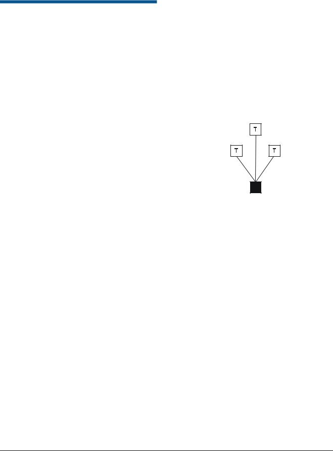
Star Network
The star network allows you to relocate devices. However, this network is not recommended in high noise environments because the extra terminations required will lower the signal to noise ratio.
A separate cable line (branch) runs from the USB module to each device. Limit branches to four.
The example below shows the USB module as the hub of a star network. The module is not terminated.
Black box = USB module, T = Terminated
Not
Terminated
ADACSNET USB CONTROL MODULE INSTALLATION GUIDE
8200-0310-01, REV. B
2 of 6
 Loading...