


American Dynamics ADCI600-D011, ADCI600-D013, ADCI600-D031, ADCI600-D033, ADCI610-D011 Installation
...illustra 600/610 Indoor IR HD Mini-dome
Installation & Operation Guide
Version: 20110902
8200-2755-04 A0

Copyright
Under copyright laws, the contents of this manual may not be copied, photocopied, reproduced, translated or reduced to any electronic medium or machine-readable form, in whole or in part, without prior written consent of Tyco International Ltd. © 2010 and its Respective Companies. All Rights Reserved.
American Dynamics
6600 Congress Avenue
Boca Raton, FL 33487 U.S.A.
Trademarks
The trademarks, logos, and service marks displayed on this document are registered in the United States [or other countries]. Any misuse of the trademarks is strictly prohibited and Tyco International Ltd. will aggressively enforce its intellectual property rights to the fullest extent of the law, including pursuit of criminal prosecution wherever necessary. All trademarks not owned by Tyco International Ltd. are the property of their respective owners, and are used with permission or allowed under applicable laws.
Product offerings and specifications are subject to change without notice. Actual products may vary from photos. Not all products include all features. Availability varies by region; contact your sales representative.
Customer Service
Thank you for using American Dynamics products. We support our products through an extensive worldwide network of dealers. The dealer through whom you originally purchased this product is your point of contact if you need service or support. Our dealers are empowered to provide the very best in customer service and support. Dealers should contact American Dynamics at (800) 507-6268 or (561) 912-6259 or on the Web at www.americandynamics.net.
i
Notice of Use
This manual is designed for administrators and users of the network camera. Please read it carefully before use. All requirements should be followed before using this camera.
We are not responsible for any technical or typographical errors and reserve the right to change the product and manuals without notice.
Keep this document for future reference.
The camera is for indoor use only.
It is intended that this camera utilizes a 12V DC, 24V AC or PoE power source that complies with LPS requirements.
The camera must be installed on a solid mounting surface.
Keep the camera and other accessories dry.
We are not responsible for any damage caused by inappropriate use.
FCC Notice
The equipment has been tested and found to comply with the limits for a Class A digital device, pursuant to Part 15 of the FCC Rules. The limits are designed to provide reasonable protection against harmful interference when the equipment is operated in a commercial environment. This equipment generates, uses, and can radiate frequency energy and, if not installed and used in accordance with the instruction manual, may cause harmful interference to radio communications.
Operation of this equipment in a residential area is likely to cause harmful interference, in which case users will be required to correct the interference at their own expense.
This device complies with Part 15 of the FCC Rules. Operation is subject to the following two conditions:
(1)this device may not cause harmful interference, and
(2)this device must accept any interference received, including interference that may cause undesired operation.
Modifications not expressly authorized by American Dynamics could void the user’s authority to operate the unit.
ii |
Installation & Operation Guide |

ICES statement
This Class A digital apparatus complies with Canadian ICES-003.
Cet appareil numérique de la classe A est conforme à la norme NMB-003 du Canada.
CE Statement
This is a Class A product. In a domestic environment this product may cause radio interference in which the user may be required to take adequate measure.
Safety Notice
The recessed indoor camera models are rated as suitable for use in environmental air handling spaces, other than inside air ducts or furnace plenums.
ESD Precautions: With the covers removed during installation and alignment this product is sensitive to electrostatic discharge. The installer should take appropriate ESD control measures such as the use of a ESD wrist strap connected to the chassis of the camera.
iii
Table of Contents |
|
|
1. Product Overview ................................................................................................................... |
1 |
|
1.1 |
Features ............................................................................................................................. |
1 |
1.2 |
Dimensions......................................................................................................................... |
2 |
1.3 |
Name of Parts .................................................................................................................... |
2 |
1.4 |
Controls/Connectors........................................................................................................... |
3 |
1.5 |
Specifications ..................................................................................................................... |
5 |
2. Camera Installation................................................................................................................. |
8 |
|
2.1 |
Accessory List .................................................................................................................... |
8 |
2.2 |
Mounting the Camera......................................................................................................... |
8 |
|
2.2.1 Preparation – Remove the dome cover and back case........................................................... |
8 |
|
2.2.2 Use the template to mark-out and prepare the mounting area ................................................ |
9 |
|
2.2.3 Connect the wiring and mount the dome enclosure .............................................................. |
11 |
3. Network Connection and Configuration ............................................................................. |
17 |
|
3.1 |
Network Connection Types .............................................................................................. |
17 |
3.2 |
Accessing the Camera for the First Time ......................................................................... |
19 |
3.3 |
Using the illustra Connect Tool to Manage Cameras....................................................... |
21 |
4. Using illustra Utility .............................................................................................................. |
22 |
|
4.1 |
Overview .......................................................................................................................... |
22 |
|
4.1.1 Main Screen ........................................................................................................................... |
22 |
|
4.1.2 PTZ Function.......................................................................................................................... |
23 |
|
4.1.3 Setup Menu............................................................................................................................ |
23 |
|
4.1.4 Applying Settings ................................................................................................................... |
24 |
4.2 |
Image ............................................................................................................................... |
25 |
|
4.2.1 Codec ..................................................................................................................................... |
26 |
|
4.2.2 Exposure ................................................................................................................................ |
29 |
|
4.2.3 White Balance ........................................................................................................................ |
32 |
|
4.2.4 Basic Settings ........................................................................................................................ |
33 |
|
4.2.5 Advanced Settings ................................................................................................................. |
33 |
|
4.2.6 Focus...................................................................................................................................... |
34 |
|
4.2.7 Privacy Zone .......................................................................................................................... |
36 |
4.3 |
Network ............................................................................................................................ |
37 |
|
4.3.1 IP & Ethernet.......................................................................................................................... |
38 |
|
4.3.2 FTP......................................................................................................................................... |
39 |
|
4.3.3 SMTP ..................................................................................................................................... |
39 |
|
4.3.4 NTP ........................................................................................................................................ |
40 |
|
4.3.5 RTSP...................................................................................................................................... |
42 |
|
4.3.6 ONVIF .................................................................................................................................... |
43 |
4.4 |
System ............................................................................................................................. |
44 |
|
4.4.1 Date & Time ........................................................................................................................... |
45 |
|
4.4.2 Firmware ................................................................................................................................ |
46 |
|
4.4.3 User Management.................................................................................................................. |
48 |
|
4.4.4 Language ............................................................................................................................... |
49 |
iv |
Installation & Operation Guide |

4.4.5 Log File................................................................................................................................... |
49 |
4.4.6 Audio ...................................................................................................................................... |
50 |
4.5 Event ................................................................................................................................ |
51 |
4.5.1 Motion Detection .................................................................................................................... |
53 |
4.5.2 External Alarms...................................................................................................................... |
54 |
4.5.3 Face Detection ....................................................................................................................... |
55 |
4.5.4 Blur Detection......................................................................................................................... |
56 |
4.5.5 Audio Detection...................................................................................................................... |
56 |
4.5.6 Ethernet Detection ................................................................................................................. |
58 |
4.5.7 Event Configuration................................................................................................................ |
58 |
4.6 Recording ......................................................................................................................... |
59 |
4.6.1 Settings – AVI ........................................................................................................................ |
59 |
4.6.2 Settings – JPEG Settings....................................................................................................... |
60 |
4.6.3 Settings – FTP ....................................................................................................................... |
60 |
4.6.4 Settings – SMTP .................................................................................................................... |
60 |
4.6.5 Settings – SD Card ................................................................................................................ |
61 |
4.6.6 Schedule – Settings ............................................................................................................... |
61 |
Appendix A. Factory Defaults.................................................................................................. |
63 |
A.1 Image Settings ................................................................................................................. |
63 |
A.2 Network Settings.............................................................................................................. |
64 |
A.3 System Settings ............................................................................................................... |
65 |
A.4 Event Settings.................................................................................................................. |
65 |
A.5 Recording Settings........................................................................................................... |
66 |
Appendix B. Firmware Updates............................................................................................... |
67 |
Appendix C. Using VLC Player to View RTSP Streaming ..................................................... |
68 |
v

1. Product Overview
1. Product Overview
This Installation & Operation Guide covers the following product codes:
illustra 600 Series |
illustra 610 Series |
ADCi600-D011 |
ADCi610-D011 |
|
|
ADCi600-D013 |
ADCi610-D013 |
|
|
ADCi600-D031 |
ADCi610-D031 |
|
|
ADCi600-D033 |
ADCi610-D033 |
|
|
1.1Features
Motion detection
Blur detection
Face detection with smart encoding allows high quality video encoding of detected faces
Remote focus adjustment (drive the motorized lens)
Smart encoding allows the user to define regions of high quality video encoding, reducing overall bandwidth
Maximum resolution 1280x720 (600 series) / 1920x1080 (610 series) provides superior image quality
Supports simultaneous streaming of H.264 and MJPEG encoded video
PoE support eliminates the need for a power cable, providing more freedom in placement
Two-way audio support, G.711 codec
Support for spot auto-exposure
Automatic exposure compensation
Configurable backlight compensation
Digital wide dynamic range
ONVIF 1.02 compliant
Digital zoom
Auto focus
1
1. Product Overview
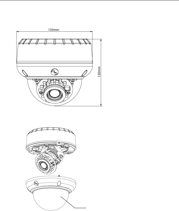
1.2 Dimensions
1.3 Name of Parts
 Back Case
Lens 
Dome Cover
2 |
Installation & Operation Guide |
1. Product Overview
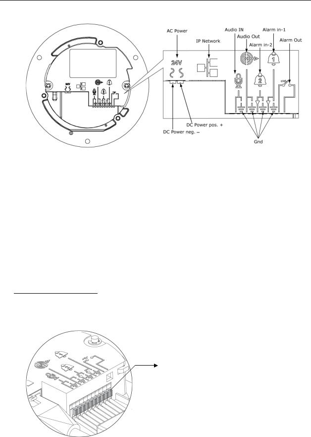
1.4 Controls/Connectors
Video System
Micro SD
Video Out
|
|
Reset |
Default |
||
|
|
|
|
|
|
Video System: NTSC / PAL system switch. Default is NTSC. Use a suitable small tool to operate the switch.
Note:
After switching the video system mode from NTSC to PAL or vice versa, you have to restore defaults to apply the changes. You can do this by either of these methods:
1.Press the Default button on the camera and release within 4 seconds to restart the camera.
2.Enter the web-based illustra utility > System > Firmware and press the Factory Default button.
Micro SD: Micro SDHC card slot.
Default:
-Factory Default: Press and release within 4 seconds to restart the camera and restore factory defaults, excluding IP settings*.
-Hardware Factory Default: Press for more than 5 seconds and then release to restart the camera and restore factory defaults, including IP settings*.
-*The IP settings include DHCP, IP address, subnet mask, default gateway, DNS and HTTP port, which are configured under Network > IP & Ethernet in the illustra utility .
Reset: Using a paper clip or thin object, press the button for at least one second and release to restart the camera.
Video Out: Analog video out RCA jack. Connects to video in connector of a monitor.
3
1. Product Overview
AC Power: Connects to DC 12V / AC 24V power supply. If you are to use power from Ethernet connection, this connector is not used when the power is provided by PoE.
IP Network Connector: Connects to the LAN port of a standard 10Base/100Base-TX device, e.g., hub, switch or router.
Audio In: Connects to an external microphone.
Audio Out: Connects to speaker.
Alarm In 1 & 2: Connects to devices that trigger alarm signals. Up to two input devices can be connected.
Alarm Out: Connects to device that responds to alarm signals, such as buzzers or lights.
GND: Ground (electricity) in electrical circuits.
Note
To connect the Audio In/Out, Alarm In/Out or GND wires, press the relevant spring terminal tab inward using an appropriate small tool and insert the wire into the opening. Then release the tab to secure the wire.
Spring terminal tab
4 |
Installation & Operation Guide |

|
|
|
|
|
|
|
|
|
1. Product Overview |
1.5 Specifications |
|
|
|
|
|
||||
|
|
|
|
|
|
|
|
|
|
|
|
|
|
|
|
illustra 600 Series |
|
|
illustra 610 Series |
|
|
|
|
|
|
ADCi600-D011 |
|
ADCi610-D011 |
|
|
|
Model List |
|
|
|
|
|
||
|
|
|
|
ADCi600-D013 |
|
ADCi610-D013 |
|||
|
|
|
|
|
|
|
|
|
|
|
|
|
|
|
|
ADCi600-D031 |
|
ADCi610-D031 |
|
|
|
|
|
|
|
|
|
|
|
|
|
|
|
|
|
ADCi600-D033 |
|
ADCi610-D033 |
|
|
|
|
Max. Resolution |
|
720p (1280x720) |
|
1080p (1920x1080) |
||
|
|
|
|
|
|
|
|
||
|
Image Sensor |
|
Pixel size |
3x3 um |
|
||||
|
|
|
|
|
|
|
|
|
|
|
|
Type |
|
CMOS |
|
||||
|
|
|
|
|
|||||
|
|
|
|
|
|
||||
|
|
|
Active Image Area |
5.856H x 3.276V mm |
|
||||
|
|
|
Type |
|
Built-in IR corrected Lens |
|
|||
|
|
|
|
|
|
||||
|
|
|
Focal Length |
3~9mm |
|
||||
|
|
|
|
|
|
|
|||
|
|
|
F No. |
|
Wide F1.2, Tele F2.1 |
|
|||
|
|
|
|
|
|
|
|||
|
Lens |
|
IRIS |
|
DC IRIS |
|
|||
|
|
|
|
|
|
|
|
|
|
|
|
Motorized |
|
Yes |
|
||||
|
|
|
|
|
|||||
|
|
|
|
|
|
|
|
||
|
|
|
Format |
1/3" |
|
|
|
||
|
|
|
|
|
|
|
|||
|
|
|
Transmittance |
|
Clear Bubble : 90% (f/0.2) [D011, D013] |
||||
|
|
|
|
Smoked Bubble: 45% (f/1.2) [D031, D033] |
|||||
|
|
|
|
|
|
||||
|
Angle of View |
|
Horizontal |
93° (wide), 31.7° (tele) |
|
||||
|
|
|
|
|
|
|
|
|
|
|
|
Vertical |
68.4° (wide), 23.8° (tele) |
|
|||||
|
|
|
|
||||||
|
Automatic |
|
NTSC |
|
1/10,000 s to 8/30 s (max and min selectable) |
||||
|
Electronic |
|
|
|
|
|
|
|
|
|
|
PAL |
|
1/10,000 s to 8/25 s (max and min selectable) |
|||||
|
Shutter Range |
|
|
||||||
|
|
|
|
|
|
|
|
|
|
|
Mechanical ICR |
|
|
|
|
True Day/Night capability with IR cut filter removal |
|||
|
|
|
IR Distance |
60 ft |
|
||||
|
|
|
|
|
|
|
|
||
|
|
|
Min. Illumination |
|
Color: 0.3 Lux @ 30IRE |
|
|||
|
IR Illuminator |
|
|
B/W: 0 Lux @ 30IRE (IR ON) |
|
||||
|
|
|
|
|
|
||||
|
|
|
Min. Safety IR distance |
|
4 feet (<1000sec) |
|
|||
|
|
|
|
|
|
||||
|
|
|
IR Wave Length |
850nm |
|
||||
|
Processor |
|
SoC |
|
DM368 |
|
|
DM368 |
|
|
Video Codec |
|
Dual simultaneous streams |
H.264, MJPEG |
|
||||
|
|
|
|
|
|
H.264: |
|
|
H.264: |
|
|
|
Max Frame Rate |
|
30fps @ 1280x720, |
|
|
30fps @ 1920x1080, |
|
|
|
|
|
|
|
30fps @ 4CIF/2CIF/CIF |
|
|
30fps @ 4CIF/2CIF/CIF |
|
|
|
|
|
|
|
|
|
|
5

1. Product Overview
|
|
|
|
MJPEG: |
|
MJPEG: |
|
|
|
|
30fps @ 1280x720, |
|
30fps @ 1920x1080, |
|
|
|
|
30fps @ 4CIF/2CIF/CIF |
|
30fps @ 4CIF/2CIF/CIF |
|
|
|
|
|
|
|
|
|
|
Codec Quality Options |
H.264: CBR(32K~8Mbps), VBR, CVBR |
||
|
|
|
MJPEG: Adjustable by value |
|||
|
|
|
|
|||
|
|
|
Codec |
G.711 Bi-directional |
|
|
|
|
|
|
|
|
|
|
|
|
Audio Frequency |
20Hz~4K Hz |
|
|
|
|
|
|
|
||
|
|
|
|
Single ended 2 k ohm equivalent impedance, 3.1 V |
||
|
Audio |
|
Audio Input |
open circuit, and max. input single level is 0.5 V |
||
|
|
rms (-6 dBV). Active type microphone (w/ external |
||||
|
|
|
|
|||
|
|
|
|
power supply) is recommended. |
||
|
|
|
|
|
||
|
|
|
Audio Output |
Single ended 10k ohm impedance and 0.9 V rms |
||
|
|
|
max line single level |
|
||
|
|
|
|
|
||
|
|
|
SD Card |
Micro SDHC |
|
|
|
|
|
|
|
||
|
|
|
|
Two with selectable activation, internal (value) pull |
||
|
|
|
Alarm In |
up to high state, and ground connection for |
||
|
|
|
external open collector or dry contact device to |
|||
|
|
|
|
|||
|
|
|
|
cause low state. |
|
|
|
Interface |
|
|
|
|
|
|
Alarm Out |
One relay output, 1A at 30VDC or 0.5A at 125VAC, |
||||
|
|
|
||||
|
|
|
selectable normal open or normal closed |
|||
|
|
|
|
|||
|
|
|
|
|
||
|
|
|
Analog Video Output |
1.0 V p-p, 75 ohm, NTSC/PAL, RCA |
||
|
|
|
|
|
|
|
|
|
|
RJ45 |
10Base/100Base-TX |
|
|
|
|
|
|
|
|
|
|
|
|
Audio In / Out |
1/1 |
|
|
|
|
|
DC 12V |
-10% ~ +10% / 9W (Max.) |
|
|
|
|
|
|
|||
|
Power |
|
AC24V |
-20%~ + 30% 47 to 63 Hz / 9W (Max.) |
||
|
|
|
PoE |
9W (Max.) |
|
|
|
Special Features |
|
Spot Auto Exposure |
Selectable |
|
|
|
|
|
|
|
|
|
|
|
|
Motion Detection |
Yes |
|
|
|
|
|
|
|
|
|
|
|
|
Face Detection |
Up to 35 faces detected |
|
|
|
|
|
|
|
|
|
|
|
|
Automatic Exposure |
Adjustable |
|
|
|
|
|
Compensation |
|
||
|
|
|
|
|
|
|
|
|
|
|
|
|
|
|
|
|
Back Light Compensation |
Selectable |
|
|
|
|
|
|
|
|
|
|
|
|
Digital Wide Dynamic |
Selectable level |
|
|
|
|
|
Range |
|
||
|
|
|
|
|
|
|
|
|
|
|
|
|
|
|
|
|
Blur Detection |
Yes |
|
|
|
|
|
|
|
|
|
|
|
|
ONVIF 1.02 Compliant |
Yes |
|
|
|
|
|
|
|
||
|
|
|
Auto Focus |
Selectable automatic or manual remote adjustment |
||
|
|
|
of lens motor |
|
||
|
|
|
|
|
||
|
|
|
|
|
|
|
6 |
Installation & Operation Guide |

1. Product Overview
|
|
|
Remote Focus Adjustment |
Yes |
|
|
|
(Drive the motorized lens) |
|
|
|
|
|
|
|
|
|
|
|
|
|
|
Smart Encoding (both user |
Up to 5 definable regions |
|
|
|
and face regions) |
|
|
|
|
|
|
|
Protocols |
|
TCP/IP, HTTP, RTP/RTSP, NTP, DHCP, FTP, SMTP, UPnP |
|
|
Support |
|
||
|
|
|
|
|
|
|
|
Dimensions |
135 x H 120mm |
|
|
|
|
|
|
Mechanical |
|
Weight |
870g |
|
|
|
Shipping Weight |
1540g |
|
|
|
Operating Temperature. |
-10 ~50 |
|
Environment |
|
Operating Humidity |
10~90% RH |
|
|
|
Storage Temperature. |
-40 ~60 |
|
|
|
Safety |
UL 60950-1 2nd Edition |
|
|
|
|
FCC |
|
|
|
|
ICES-003/NMB-003 class A |
|
|
|
EMC |
AS/NZS CISPR 22 class A |
|
Regulatory |
|
|
EN50130-4 |
|
|
|
EN55022 class A |
|
|
|
|
|
|
|
|
|
|
|
|
|
|
|
RoHS compliant |
|
|
|
Other |
WEEE applicable |
|
|
|
|
Reach compliant |
|
|
|
Markings |
CE, UL, C-Tick |
7
2. Camera Installation
2. Camera Installation
2.1 Accessory List
|
Security Torx Key |
x 1 |
|
Screw hole plug |
x 4 |
|
Screw |
x 4 |
|
Anchor |
x 4 |
|
Guide Pattern Template |
x 2 |
|
CD-ROM |
x 1 |
|
Fire Protection Cover |
x 1 |
|
Quick Start Guide |
x 1 |
2.2 Mounting the Camera
2.2.1 Preparation – Remove the dome cover and back case.
1. Use the supplied security torx key to loosen (not remove) the three cover screws.
2. Loosen the three screws (marked with the triangle icon) on the dome base.
3. Remove the back case.
8 |
Installation & Operation Guide |
2. Camera Installation
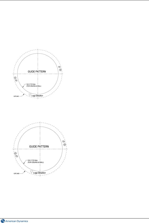
2.2.2 Use the template to mark-out and prepare the mounting area
Method 1: To flush mount using screws
1.Create a circular opening in the mounting surface with a diameter of 110 mm (4.3”) with tolerances of -0/+5 mm (-0/.0.2”).
2.Create two 6 mm (0.2”) holes at the T3 template positions. Then insert the screw anchors into the holes.
Method 2: To flush mount using locking arms
Create a circular opening in the mounting surface with a diameter of 110 mm (4.3”) with tolerances of - 0/+5 mm (-0”/.0.2”).
9

2. Camera Installation
Method 3: To surface mount
1.According to your needs, create 6mm (0.2”) holes at the T1/T2 template positions. Then insert the screw anchors into the holes.
2.If you want to feed wiring from the hole on the top of the back case, create a circular opening (bottom conduit hole) in the mounting surface.
Method 4: To surface mount using junction box
No need to mark-out and prepare the mounting areas. Skip to next section for mounting instructions.
10 |
Installation & Operation Guide |
2. Camera Installation
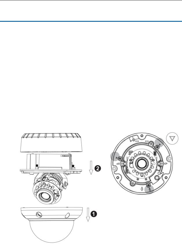
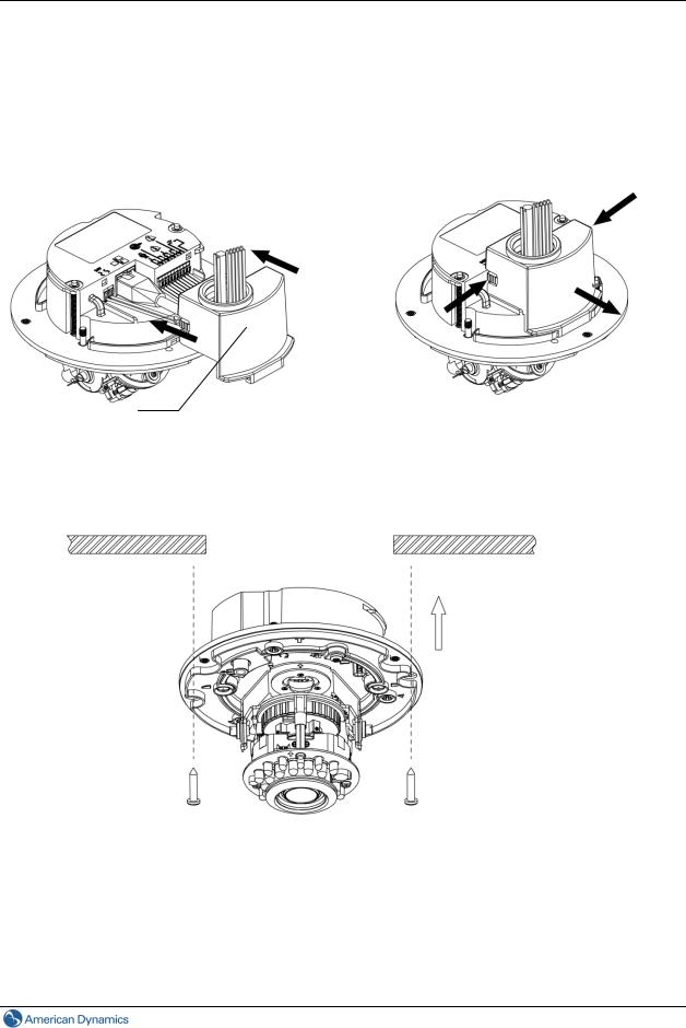
2.2.3 Connect the wiring and mount the dome enclosure
Method 1: To Flush Mount the Dome using screws
1.Firstly, feed the leads through the fire protection cover, then connect the wiring and assemble the fire protection cover.
Fire protection cover |
If you need to disassemble the fire protection |
|
|
|
cover, press both buttons on each side and |
|
then pull out. |
2. Fasten the two TP4 screws to the inserted anchors to secure the dome enclosure in place.
11
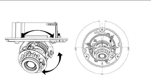
2.Camera Installation
3.Adjust the focusing position by rotating and panning the camera base. When rotating the camera base, do not rotate it past the stop point.
4.Use the supplied security torx key to tighten the three cover screws to replace the dome cover.
5.Finally, insert the screw hole plugs to the three cover screws.
12 |
Installation & Operation Guide |
2. Camera Installation
Method 2: Flush mount using locking arms
1.Turn the silver-colored screws clockwise to extend the locking arms.
2.Tighten the screws sufficiently to compress the arms to adjust to the mounting surface.
Locking arms
Tighten the screws
3. Adjust the focusing position by rotating and panning the camera base. When rotating the camera base, do not rotate it past the stop point.
4.Use the supplied security torx key to tighten the three cover screws to replace the dome cover.
5.Finally, insert the screw hole plugs to the three cover screws.
13
2. Camera Installation
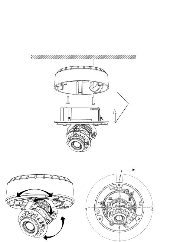
Method 3: To surface mount
1.According to your needs, use the top or side knock-out on the back case for cable entry and connect the wiring. Mount the back case on a surface with screws.
2.Align the back case and the lens base, and then fasten the TP4 screws into the inserted anchors. There is a red dot on the back case and the lens base respectively. Use the dots to align the case and the base.
 Top knock-out
 Side knock-out
Use the red dots on back case and lens base for alignment.
3. Adjust the focusing position by rotating and panning the camera base. Note that the back case side
conduit hole is the point where the camera will not rotate past.
Side conduit hole
4.Use the supplied security torx key to tighten the three cover screws to replace the dome cover.
5.Finally, insert the screw hole plugs to the three cover screws.
14 |
Installation & Operation Guide |

2. Camera Installation
Method 4: To surface mount using junction box
1.Tie your wiring into a junction box and feed the leads through the top knock-out on the back case.
2.Tighten the electrical screws to secure the back case to the junction box. Then connect the wiring.
3.Align the back case and the lens, and then fasten the three screws. There is a red dot on the base case and the lens base respectively. Use the dots to align the case and the base.
Use the red dots on back case and lens base for alignment.
4. Adjust the focusing position by rotating and panning the camera base. Note that the back case side conduit hole is the point where the camera will not rotate past.
 Side conduit hole
15

2. Camera Installation
5.Use the supplied security torx key to tighten the three cover screws to replace the dome cover.
6.Finally, insert the screw hole plugs to the three cover screws.
16 |
Installation & Operation Guide |
 Loading...