


 Loading...
User Manual & Web Client Guide
TVR-LT Digital Video Recorder
Version 2.50
8200-0612-01 A0

Notice
The information in this manual was current when published. The manufacturer reserves the right to revise and improve its products. All specifications are therefore subject to change without notice.
Copyright
Under copyright laws, the contents of this manual may not be copied, photocopied, reproduced, translated or reduced to any electronic medium or machine-readable form, in whole or in part, without prior written consent of Tyco International Ltd. ©2010 and its Respective Companies. All Rights Reserved.
American Dynamics 6600 Congress Avenue
Boca Raton, FL 33487 U.S.A.
Customer Service
Thank you for using American Dynamics products. We support our products through an extensive worldwide network of dealers. The dealer through whom you originally purchased this product is your point of contact if you need service or support. Our dealers are empowered to provide the very best in customer service and support.
Trademarks
The trademarks, logos, and service marks displayed on this document are registered in the United States [or other countries]. Any misuse of the trademarks is strictly prohibited and Tyco International Ltd. will aggressively enforce its intellectual property rights to the fullest extent of the law, including pursuit of criminal prosecution wherever necessary. All trademarks not owned by Tyco International Ltd. are the property of their respective owners, and are used with permission or allowed under applicable laws.
Product offerings and specifications are subject to change without notice. Actual products may vary from photos. Not all products include all features. Availability varies by region; contact your sales representative.
License Information
Read this license agreement before opening the disk package, downloading the software, installing the software, or using your system. This license agreement defines your rights and obligations. By breaking the seal on this package, installing the software, or using your system, you agree to all of the terms and conditions of this agreement. If you do not agree to all of the terms and conditions of this agreement, you may, within 30 days, return this package, all the documentation, and all accompanying material(s) to the point of purchase for a refund.
Software License
The Software includes the computer code, programs, and files, the associated media, hardware or software keys, any printed material, and any electronic documentation. The Software may be provided to you pre-installed on a storage device (the media) as part of a system. The Software is licensed, not sold.
Grant of License
This agreement between Sensormatic Electronics Corporation (Sensormatic) and you permits you to use the Software you purchased. Once you have purchased the number of copies you require, you may use the Software and accompanying material provided you install and use no more than the licensed number of copies at one time. The Software is only licensed for use with specified Sensormatic supplied equipment. If the Software is protected by a software or hardware key or other device, the Software may be used on any computer where the key is installed. If the key locks the Software to a particular System, the Software may only be used on that System.
Other Rights and Limitations
•A demonstration copy of the Software is considered purchased and is covered by this license agreement.
•You may not de-compile, disassemble, reverse engineer, copy, transfer, modify, or otherwise use the Software except as stated in this agreement.
•The hardware/software key, where applicable, is your proof of license to exercise the rights granted herein and must be retained by you. Lost or stolen keys will not be replaced.
•If the Software is provided as part of a System, the Software may only be used with the System.
i

•You may not sub-license, rent or lease the Software, but you may permanently transfer the Software to another party by delivering the original disk and material comprising the Software package as well as this license agreement to the other party. Initial use of the Software and accompanying material by the new user transfers the license to the new user and constitutes the new user's acceptance of its terms and conditions.
•The Software is not fault tolerant and may contain errors. You agree that the Software will not be used in an environment or application in which a malfunction of the Software would result in foreseeable risk of injury or death to the operator of the Software, or to others.
•Sensormatic reserves the right to revoke this agreement if you fail to comply with the terms and conditions of this agreement. In such an event, you must destroy all copies of the Software, and all of its component parts (e.g., documentation, hardware box, software key).
•The Software may contain software from third parties that is licensed under a separate End User License Agreement (EULA). Read and retain any license documentation that may be included with the Software. Compliance with the terms of any third party EULA is required as a condition of this agreement.
•The Software may require registration with Sensormatic prior to use. If you do not register the Software this agreement is automatically terminated and you may not use the Software.
Upgrades and Updates
Software Upgrades and Updates may only be used to replace all or part of the original Software. Software Upgrades and Updates do not increase the number copies licensed to you. If the Software is an upgrade of a component of a package of Software programs that you licensed as a single product, the Software may be used and transferred only as part of that single product package and may not be separated for use on more than one computer. Software Upgrades and Updates downloaded free of charge via a Sensormatic authorized World Wide Web or FTP site may be used to upgrade multiple systems provided that you are licensed to use the original Software on those systems.
Tools and Utilities
Software distributed via Sensormatic authorized World Wide Web or FTP site as a tool or utility may be copied and installed without limitation provided that the Software is not distributed or sold and the Software is only used for the intended purpose of the tool or utility and in conjunction with Sensormatic products. All other terms and conditions of this agreement continue to apply.
Failure to comply with any of these restrictions will result in automatic termination of this license and will make available to Sensormatic other legal remedies.
Copyright
The Software is a proprietary product of Tyco International Ltd. and is protected by both the United States and International copyright laws.
Limited Warranty
Sensormatic warrants that the recording medium on which the Software is recorded, hardware key, and the documentation provided with it, will be free of defects in materials and workmanship under normal use for a period of ninety (90) days from the date of delivery to the first user. Sensormatic further warrants that for the same period, the software provided on the recording medium under this license will substantially perform as described in the user documentation provided with the product when used with the specified hardware.
Customer Remedies
Sensormatic's entire liability and your exclusive remedy under this warranty will be, at Sensormatic's option, to a) attempt to correct software errors with efforts we believe suitable to the problem, b) replace at no cost the recording medium, software or documentation with functional equivalents as applicable, or c) refund the license fee and terminate this agreement. Any replacement item will be warranted for the remainder of the original warranty period. No remedy is provided for failure of the Software if such failure is the result of accident, abuse, alteration or misapplication. Warranty service or assistance is provided at the original point of purchase.
No Other Warranties
The above warranty is in lieu of all other warranties, express or implied, including, but not limited to the
ii |
TVR-LT User Manual & Web Client Guide V2.50 |

implied warranties of merchantability and fitness for a particular purpose. No oral or written information or advice given by Sensormatic, its representatives, distributors or dealers shall create any other warranty, and you may not rely on such information or advice.
No Liability for Consequential Damages
In no event will Sensormatic be liable to you for damages, including any loss of profits, loss of data or other incidental or consequential damages arising out of your use of, or inability to use, the Software or its documentation. This limitation will apply even if Sensormatic or an authorized representative has been advised of the possibility of such damages. Further, Sensormatic does not warrant that the operation of the Software will be uninterrupted or error free. This limited warranty gives you specific legal rights. You may have other rights that vary from state to state. Some states do not allow the exclusion of incidental or consequential damages, or the limitation on how long an implied warranty lasts, so some of the above limitations may not apply to you.
General
If any provision of the agreement is found to be unlawful, void, or for any reason unenforceable, then that provision shall be severed from this agreement and shall not affect the validity and enforceability of the remaining provisions. This agreement is governed by the laws of the State of Florida. You should retain proof of the license fee paid, including model number, serial number and date of payment, and present such proof of payment when service or assistance covered by this warranty is requested.
U.S. Government Restricted Rights
The software and documentation are provided with RESTRICTED RIGHTS. Use, duplication, or disclosure by the Government is subject to restrictions as set forth in subparagraph (c)(1)(ii) of the Rights in Technical Data and Computer Software clause at DFARS 252.227-7013 or subparagraph (c)(1) and (2) of the Commercial Computer Software-Restricted Rights at 48 CFR 52.227-19, as applicable. Manufacturer is Sensormatic Electronics Corporation, 6600 Congress Avenue, Boca Raton, FL, 33487.
iii

Warnings
To reduce risk of electric shock, do not remove cover. No user serviceable parts inside. Refer servicing to qualified service personnel.
Do not expose this appliance to rain or moisture.
Do not install this product in hazardous areas where highly combustible or explosive products are stored or used.
The lightning flash/arrowhead symbol, within an equilateral triangle, alerts the user to the presence of a shock hazard within the product’s enclosure.
I.T.E
E178610
Underwriters Laboratories Inc. (“UL”) has not tested the performance or reliability of the security or signaling
aspects of this product. UL has only tested for fire, shock or casualty hazards as outlined in the UL's Standard for Safety UL 60950-1. UL Certification does not cover the performance or
reliability of the security or signaling aspects of this product. UL makes no representations, warranties or certifications whatsoever regarding the performance or reliability of any security or signaling related functions of this product.
“CAUTION: Risk of Explosion if battery is replaced by an incorrect type, dispose of used batteries according to the battery manufacturer’s instructions.”
This equipment has been tested and found to comply with the limits for a Class “B” digital device, pursuant to part 15 of the FCC Rules. These limits are designed to provide reasonable protection against harmful interference when the equipment is operated in a commercial environment. This equipment generates uses and can radiate radio frequency energy and, if not installed and used in accordance with the instruction manual, may cause interference to radio communications. Operation of this equipment in a residential area is likely to cause harmful interference in which case the user will be required to correct the interference at their own expense.
Changes or modifications not expressly approved by Sensormatic the party responsible for FCC compliance, could void the user’s authority to operate the equipment.
This product was FCC verified under test conditions that included the use of shielded I/O cables and connectors between system components. To be in compliance with FCC regulations, the user must use shielded cables and connectors for all except power and alarm cables.
This class B digital apparatus complies with Canadian ICES-003.
Cet appareil numérique de la classe B est conforme à la norme NMB-003 du Canada.
iv |
TVR-LT User Manual & Web Client Guide V2.50 |

____________________Table of Contents
Part I Local Device Operation............................................................................................................. |
1 |
||
Chapter 1 Introduction ............................................................................................................................ |
0 |
||
1.1 |
Overview ................................................................................................................... |
0 |
|
1.2 |
Key Product Features ............................................................................................... |
0 |
|
1.3 |
Product Application Diagram .................................................................................... |
2 |
|
1.4 |
Operating Your TVR.................................................................................................. |
2 |
|
1.5 |
Using the Front Panel Controls................................................................................. |
2 |
|
1.6 |
Using the IR Remote Control.................................................................................... |
4 |
|
1.7 |
Using a USB Mouse ................................................................................................. |
5 |
|
1.8 |
Using the On-Screen Keyboard................................................................................ |
6 |
|
1.9 |
Rear Panel Diagram ................................................................................................. |
6 |
|
Chapter 2 Getting Started ....................................................................................................................... |
8 |
||
2.1 |
Starting and Shutting Down Your TVR...................................................................... |
8 |
|
2.2 |
Rebooting and Locking Your TVR-LT ....................................................................... |
8 |
|
2.3 |
Switch user ............................................................................................................... |
9 |
|
2.4 |
Using the Setup Wizard ............................................................................................ |
9 |
|
2.5 |
Setting Date & Time................................................................................................ |
12 |
|
Chapter 3 Live Preview........................................................................................................................... |
14 |
||
3.1 |
Live Preview............................................................................................................ |
14 |
|
3.2 |
Understanding Live Preview Icons ......................................................................... |
14 |
|
3.3 |
Live Preview Related Operations ........................................................................... |
14 |
|
3.4 |
Using the Mouse in Live Preview............................................................................ |
14 |
|
3.5 |
Using Digital Zoom ................................................................................................. |
16 |
|
3.6 |
Configuring Live Preview Displays ......................................................................... |
16 |
|
3.7 |
Setting Camera Order............................................................................................. |
17 |
|
Chapter 4 Recording Settings................................................................................................................. |
18 |
||
4.1 |
Configuring Recording Parameters ........................................................................ |
18 |
|
4.1.1 |
Initializing Record Settings.............................................................................. |
18 |
|
4.1.2 Scheduling a Recording ........................................................................................ |
20 |
||
4.2 |
Protecting Recorded Files ...................................................................................... |
21 |
|
4.2.1 Locking and Unlocking Recorded Files ................................................................. |
21 |
||
4.2.2 Setting HDD to Read-Only .................................................................................... |
22 |
||
4.3 |
Configuring Advanced HDD Settings...................................................................... |
23 |
|
4.3.1 Setting up HDD Redundancy ................................................................................ |
23 |
||
Chapter 5 Playback ................................................................................................................................. |
25 |
||
5.1 |
Playing a Recording................................................................................................ |
25 |
|
5.1.1 |
Understanding the Playback Interface ............................................................ |
25 |
|
5.1.2 |
Playing Back from Search............................................................................... |
26 |
|
5.1.3 |
Playing Back from Live Preview...................................................................... |
27 |
|
5.1.4 |
Playing Back from System Log ....................................................................... |
27 |
|
5.1.5 |
Playing Back Frame-by-Frame ....................................................................... |
28 |
|
5.1.6 |
Reverse Playback ........................................................................................... |
28 |
|
5.2 |
Using Digital Zoom ................................................................................................. |
29 |
|
To use digital zoom in Playback mode:.............................................................................. |
29 |
||
Chapter 6 Backup.................................................................................................................................... |
30 |
||
6.1 |
Back up Recorded Files.......................................................................................... |
30 |
|
6.1.1 |
Exporting Files ................................................................................................ |
30 |
|
6.1.2 |
Exporting Video Clips...................................................................................... |
32 |
|
6.1.3 |
Managing Backup Devices ............................................................................. |
32 |
|
Chapter 7 Alarm Settings........................................................................................................................ |
34 |
||
7.1 |
Configuring Alarms ................................................................................................. |
34 |
|

7.1.1 |
Setting up Motion Detection............................................................................ |
34 |
|
7.1.2 |
Setting up Video Tamper................................................................................. |
36 |
|
7.1.3 |
Setting up Sensor Alarms ............................................................................... |
38 |
|
7.2 |
Triggering Alarm Outputs Manually ........................................................................ |
40 |
|
7.3 |
Detecting Video Loss.............................................................................................. |
41 |
|
7.4 |
Setting Exception.................................................................................................... |
42 |
|
7.5 |
Understanding Exception Trigger Options.............................................................. |
43 |
|
Chapter 8 Network Settings.................................................................................................................... |
44 |
||
8.1 |
|
Configuring Basic Settings.............................................................................. |
44 |
8.2 |
|
Configuring PPPoE Settings ........................................................................... |
45 |
8.3 |
|
Configuring DDNS........................................................................................... |
45 |
8.4 |
|
Configuring an NTP Server ............................................................................. |
46 |
8.5 |
|
Configuring a Remote Alarm Host .................................................................. |
47 |
8.6 |
|
Configuring Multicast....................................................................................... |
48 |
8.7 |
|
Configuring Server and HTTP Ports ............................................................... |
48 |
8.8 |
|
Configuring E-mail Settings ............................................................................ |
49 |
Chapter 9 PTZ Controls ......................................................................................................................... |
50 |
||
9.1 |
Navigating PTZ Menus ........................................................................................... |
50 |
|
9.2 |
Configuring PTZ Settings........................................................................................ |
50 |
|
9.3 |
Setting PTZ Presets, Sequences & Patterns.......................................................... |
51 |
|
9.3.1 |
Understanding PTZ Controls .......................................................................... |
51 |
|
9.3.2 |
Customizing Presets ....................................................................................... |
52 |
|
9.3.3 |
Customizing Sequences ................................................................................. |
52 |
|
9.3.4 |
Virtual Sequence............................................................................................. |
54 |
|
9.3.5 |
Customizing Patterns ...................................................................................... |
55 |
|
Chapter 10 Camera Management.......................................................................................................... |
56 |
||
10.1 |
Configuring OSD Settings....................................................................................... |
56 |
|
10.2 |
Setting up Privacy Mask ......................................................................................... |
56 |
|
10.3 |
Adjusting Display Settings ...................................................................................... |
57 |
|
Chapter 11 HDD Management............................................................................................................... |
59 |
||
11.1 |
Managing HDDs...................................................................................................... |
59 |
|
11.1.1 |
Initializing HDDs.............................................................................................. |
59 |
|
11.1.2 |
Setting HDD Groups ....................................................................................... |
59 |
|
11.2 |
Setting HDD Status................................................................................................. |
60 |
|
Chapter 12 TVR-LT Management ......................................................................................................... |
63 |
||
12.1 |
Configuring System Settings .................................................................................. |
63 |
|
12.2.1 |
Configuring General Settings.......................................................................... |
63 |
|
12.2.2 |
Configuring Advanced Settings....................................................................... |
63 |
|
12.2.3 |
Configuring RS-232 Port Settings................................................................... |
64 |
|
12.2 |
Managing User Accounts........................................................................................ |
65 |
|
12.2.1 |
Adding a New User ......................................................................................... |
65 |
|
12.2.2 |
Deleting a User ............................................................................................... |
67 |
|
12.2.3 |
Modifying a User ............................................................................................. |
67 |
|
12.3 |
Managing the System ............................................................................................. |
68 |
|
12.4 |
Upgrading System Firmware .................................................................................. |
68 |
|
12.5 |
Restoring Default Settings ...................................................................................... |
69 |
|
12.6 |
Viewing System Information ................................................................................... |
70 |
|
12.7 |
Viewing System Logs.............................................................................................. |
70 |
|
Part II Web Client Operation .............................................................................................................. |
72 |
||
Chapter 1 Web Client Introduction ....................................................................................................... |
73 |
||
1.1 Install Web Client.......................................................................................................... |
73 |
||
1.2 Notes for IE 7&8 on Windows Vista and Windows 7.................................................... |
74 |
||
1.2.1 Run web browser as administrator............................................................................ |
76 |
||
1.2.2 Always run web browser with administrator privileges.............................................. |
77 |
||
1.2.3 Disable the ‘Protected Mode’ for IE 7&8 ................................................................... |
78 |
||
Chapter 2 Login and Logout .................................................................................................................. |
79 |
||

Chapter 3 Preview ................................................................................................................................... |
81 |
|
3.1 |
Preview......................................................................................................................... |
82 |
3.1.1 Panes..................................................................................................................... |
82 |
|
3.1.2 Live view................................................................................................................ |
82 |
|
3.1.3 Live view control .................................................................................................... |
83 |
|
3.1.4 Stop preview.......................................................................................................... |
84 |
|
3.2 |
Start recording and take a snap shot ........................................................................... |
84 |
3.2.1 Instant Recording .................................................................................................. |
84 |
|
3.2.2 Snap shot .............................................................................................................. |
85 |
|
3.3 |
Voice talk ...................................................................................................................... |
85 |
3.4 |
Image parameters ........................................................................................................ |
86 |
Chapter 4 PTZ ......................................................................................................................................... |
87 |
|
4.1 |
Customizing Presets .................................................................................................... |
88 |
4.2 |
Customizing Sequences............................................................................................... |
88 |
4.3 |
Customizing Patterns ................................................................................................... |
89 |
Chapter 5 Playback ................................................................................................................................. |
90 |
|
5.1 |
Video search................................................................................................................. |
90 |
5.2 |
Play video..................................................................................................................... |
91 |
5.3 |
Screenshot and download............................................................................................ |
92 |
Chapter 6 Log .......................................................................................................................................... |
94 |
|
Chapter 7 Configuration......................................................................................................................... |
95 |
|
7.1 |
Local configuration ....................................................................................................... |
95 |
7.2 |
Export and import TVR-LT configuration file ................................................................ |
96 |
7.3 |
Remote Configuration .................................................................................................. |
97 |
7.3.1 Device Parameters ................................................................................................ |
97 |
|
7.3.2 Channel Parameters.............................................................................................. |
98 |
|
7.3.3 Network Parameters............................................................................................ |
108 |
|
7.3.4 Serial Port Parameters ......................................................................................... |
113 |
|
7.3.5 Alarm Parameters................................................................................................. |
114 |
|
7.3.6 Exception Parameters .......................................................................................... |
117 |
|
7.3.7 Account Management........................................................................................... |
117 |
|
7.3.8 Hard drive Settings ............................................................................................... |
119 |
|
7.3.9 Upgrade Remotely................................................................................................ |
119 |
|
7.3.10 DST Settings ...................................................................................................... |
119 |
|
Part III Appendices ............................................................................................................................. |
121 |
|
Glossary ........................................................................................................................... |
122 |
|
Frequently Asked Questions ............................................................................................ |
123 |
|
Recommended Bit Rate ................................................................................................... |
124 |
|
How to Replace the Motherboard Battery ........................................................................ |
125 |
|
How to Preview via Touch Tracker ADTT16E .................................................................. |
127 |
|
How to Control SensorNet Dome via the ADACSNETH USB Module............................. |
130 |
|

Part I Local Device Operation
1
1 Introduction
Chapter 1 Introduction
1.1 Overview
Thank you for your purchase of TVR-LT series Digital Video Recorder (DVR). To get the most out of your TVR, please read through the User’s Manual and Web Client Guide thoroughly.
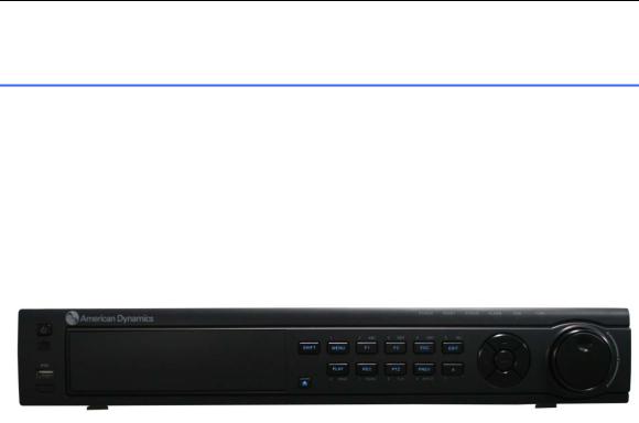
The TVR-LT series DVR, shown in Figure 1-1, is a new generation product developed by Tyco. Built on an embedded platform and combining the latest in advanced H.264 video encoding and decoding technologies, the TVR-LT is the perfect combination of rock-solid reliability and high performance.
Figure 1-1
1.2 Key Product Features
Compression
•Supports PAL/NTSC video input.
•Adopts the H.264 video compression standard.
•Video encoding parameters of each channel can be set separately, including stream type, resolution, frame rate, bit rate and image quality.
•Each channel supports two sets of compression parameters, i.e. normal continuous compression and event compression.
•Supports both composite (video & audio) stream and video stream. Audio and video streams
are strictly simultaneous.
Monitoring
•High definition VGA display supports 1024*768 resolution.
•Supports 1/4/9/16 screen live view, channel sequence is adjustable.
•Supports live view group switch, manual switch and automatic switch. The interval of automatic switch can be adjusted.
•Supports digital zoom on live view.
•Supports shielding the assigned live view channel.
•Supports motion detection, view tampering alert, video exception alert and video loss alert.
•Supports privacy mask.
•Supports various PTZ protocols, PTZ preset, sequence and pattern.
•Supports zoom in by clicking the mouse and trace function by dragging.
HDD Management
•Supports 4 SATA HDD. Each HDD can support up to 2TB capacity.
•Supports S.M.A.R.T. technology.
•Supports HDD standby function.
•Supports hard disk group management.
0 |
TVR-LT User Manual & Web Client Guide V2.50 |
1 Introduction
•HDD file system is compatible with Windows. Uses pre-allocating hard disk management technology with no disk fragments.
Recording and Playback
•Supports cycle and non-cycle recording mode.
•Supports normal and event video encoding parameters.
•Supports multiple recording types, including continuous, alarm, motion, motion | alarm and motion & alarm.
•Supports 8 recording time periods with separate recording types.
•Supports pre-record and post-record time for alarm and motion detection.
•Supports locking and unlocking video files.
•Supports local redundant recording.
•Supports setting hard disk to read only.
•Supports video data search and playback by channel number, recording type, time and file type.
•Supports digital zoom function in playback.
•Supports pause, fast forward, play slow, skip forward, and skip backward when in playback, locating in progress bar by dragging the mouse.
•Supports synchronous playback of up to 8 channels (TVRLT08XXX and TVRLT16XXX).
Data Backup
•Supports USB device backup.
•Supports SATA CD/DVD-R/W backup.
•Supports backup by file or by time.
•Supports backup device maintenance and management.
•Supports video clips backup when in playback.
Alarm & Exception
•Supports alarm in/out and arming schedule setting.
•Supports various alarm input such as hard disk full, illegal access, network break, IP conflicted, hard disk error, video exception, and video output standard mismatch.
•Supports various alarm response such as camera recording, relay out, on-screen warning, audible warning, notify remote client and send email.
•Supports auto recovery from exceptions.
Network
•Supports 10/100M adaptive network interface.
•Supports TCP/IP protocols, PPPoE, DHCP, DNS, DDNS, NTP, and SADP.
•Supports unicast and multicast, support TCP, UDP, and RTP for unicast.
•Supports remote search, playback and download video files, supports breakpoint resume.
•Supports remote configuration, supports remote import and export of DVR settings.
•Supports remote acquisition of device status, system log and alarm status.
•Supports remote button operation, remote locking and unlocking of panel buttons.
•Supports remote format of hard disk, upgrade, reboot, shutdown and other system maintenance operations.
•Supports RS-232 and RS-485 transparent channel transmission.
•Supports event alarm and exceptions upload to remote management host.
•Supports remote PTZ control.
•Supports voice talk and broadcast.
•Built-in WEB Server.
Other
•Supports front panel, mouse, and IR control.
•Supports multi-level user management. Each user can have individual DVR access rights.
1
1 Introduction
• Powerful DVR log, including operation, alarm and exception log.
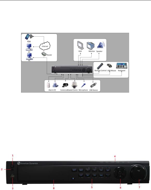
1.3 Product Application Diagram
Figure 1-2 Product Application Diagram
1.4 Operating Your TVR
There are several ways to navigate and operate your TVR-LT. You may use the Front Panel, the included IR (Infra-Red) Remote Control, a Mouse and the On-screen Keyboard.
1.5 Using the Front Panel Controls
Your TVR-LT comes with built-in front panel controls, as shown in Figure 1-3.
Figure 1-3 TVR-LT Front Panel Controls
The controls on the front panel include:
1.POWER Button: The POWER button is used to power on or power off the DVR.
2.IR Receiver: Receives signals from IR Remote Control.
3.USB Port: Universal Serial Bus (USB) ports for additional devices such as USB mouse or USB Hard Disk Drive (HDD).
2 |
TVR-LT User Manual & Web Client Guide V2.50 |

1 Introduction
4. Status Indicators: Status indicators for different features of the TVR-LT.
• POWER: Power indicator flashes green when the DVR is powered on.
• Status: Status indicator turns green when the DVR is controlled by an IR remote. It turns red when SHIFT button is pressed to enable letter/numeric input mode.
•Ready: Ready indicator turns blue when the DVR is functioning properly.
•Alarm: Alarm indicator turns red when a sensor alarm is detected.
•HDD: HDD indicator flashes red when data is being read from or written to the HDD.
•Tx/Rx: Tx/Rx indictor flickers green when network connection is functioning properly.
5.Control Buttons:
•1/MENU Button: The 1/MENU button works as numeric [1]. Pressing this button will return
the user to the Main menu (after successful login). The 1/MENU button will also bring up Sensitivity Interface settings.
•2ABC/F1: The 2ABC button works as numeric [2] and letters [ABC]. When used in a list field it will select all items on the list.
•3DEF/F2: The 3DEF button works as numeric [3] and letters [DEF]. It is also used to cycle
through tab pages.
•4GHI/ESC: The 4GHI/ESC button works as numeric [4] and letters [GHI], it is also used to escape to the previous menu
•5JKL/EDIT: The 5JKL/EDIT button works as numeric [5] and letters [JKL]. The 5JKL/EDIT
button is used to edit text fields. When editing text fields, it will also function as a Backspace button to delete the character in front of the cursor. On checkbox fields, pressing the 5JKL/EDIT button will tick the checkbox. In Playback mode, it can be used to generate video clips for backup. In Export/Import mode, it can be used to navigate file folders.
•6MNO/PLAY: The 6MNO/PLAY button works as numeric [6] and letters [MNO]. It is used to enter the Playback menu. It is also used to turn audio on/off in the Playback menu.
•7PQRS/REC: The 7PQRS/REC button works as numeric [7] and letters [PQRS].
•8TUV/PTZ: The 8TUV/PTZ button works as numeric [8] and letters [TUV]. It is also used to
enter the PTZ Control mode.
•9WXYZ/PREVIEW: The 9WXYZ/PREVIEW button works as numeric [9] and letters [WXYZ]. It is also used to switch between single screen and multi-screen mode.
•0/A: The 0/A button works as numeric [0]. It is also used to switch between input methods
(upper and lowercase alphabet, symbols and numeric input). It can also be used to clear entire masked areas, such as in the Motion Detection and Privacy Mask menus.
• SHIFT: The SHIFT button is used to switch the button function between a numeric button and a control button.
Note
Only English letters and numbers 0-9 can be typed via the front panel.
6.DIRECTION/ENTER Buttons:
• DIRECTION Buttons: The DIRECTION buttons are used to navigate between different fields
and items in menus. They have various functions in different modes:
In Playback mode, pressing the Up or Down button once will speed up or slow down recorded video. Pressing the Left or Right button once will jump 5s forward or backward. Pressing the Left or Right button twice within 1s will jump 15s forward or backward. Pressing the Left or Right button three times within 1s will jump 30s forward or backward. The Left and Right buttons will select the next and previous day of recordings.
In Preview mode, these buttons can be used to cycle through channels.
In PTZ Control mode, pressing the Left or Right button twice within 1s or holding it for 1s makes the PTZ camera pan left or right. Pressing the Up or Down button twice within 1s or holding it for 1s makes the PTZ camera tilt up or down. Pressing the Up button and then the Left button within 1s makes the PTZ move in the upper left direction. The order of these two buttons is not restricted. PTZ movements in directions upper right, lower left and lower right can be controlled by similarly pressing the appropriate adjoining two buttons within a 1s interval.
3

1Introduction
•ENTER Button: The ENTER button is used to confirm a selection in any of the menu modes. It can also be used to tick checkbox fields. In Playback mode, it can be used to play or pause the video. In Single Play mode, pressing the ENTER button will advance the video by a single frame.
7.JOG SHUTTLE Control: The JOG SHUTTLE control can be used to move the active selection in a menu. The inner ring will move the selection up and down. The outer ring will move it left and right. In the Playback mode, the outer ring is used to jump 30s forward/backward in video files. Button F1 can be used to switch from playback to adverse playback, or vice versa. The inner ring can be used to speed up/slow down the video. In Preview mode, it can be used to cycle through different channels.
8.DVD-ROM: Slot for DVD-ROM. (Optional)
Note
It is important to note that you must click the EDIT button on either the remote or the front panel on a text field before being able to edit its content. After entering text, you must press the ENTER button to be able to move onto the next field.
1.6 Using the IR Remote Control
Your TVR-LT may also be controlled with the included IR remote control, shown in Figure 1-4. 2xAAA batteries must be installed before operating.
Figure 1-4 IR Remote Control
The keys on the remote control closely resemble the ones found on the front panel, including:
1.POWER: Turn DVR on/off.
2.DEV: Enable/Disable Remote Control.
3.Alphanumeric: Same as Alphanumeric buttons on front panel.
4.EDIT: Same as JKL/EDIT button on front panel.
5.A: Same as 0/A button on front panel.
6.REC: Same as 7PQRS/REC button on front panel.
4 |
TVR-LT User Manual & Web Client Guide V2.50 |

1 Introduction
7.PLAY: Same as 6MNO/PLAY button on front panel.
8.INFO: Reserved.
9.VOIP: Same as 2ABC/F1 button on front panel.
10.MENU: Same as 1/MENU button on front panel.
11.PREV: Same as 9WXYZ/PREV button on front panel.
12.DIRECTION/ENTER Buttons: Same as DIRECTION/ENTER buttons on front
panel.
13.PTZ: Same as 8TUV/PTZ button on front panel.
14.ESC: Same as ESC button on front panel.
15.RESERVED: Reserved.
16.F1: Same as 2ABC button on front panel.
17.PTZ CONTROL Buttons: Buttons to adjust the iris, focus and zoom of a PTZ
camera.
18.F2 Button: The F2 button is used to cycle through tab pages. It can also be used to enter the Channel and OSD Position settings.
Point the remote control at the IR receiver located at the front of the unit to test its operation. If there is no response:
1.Using the front control panel or the mouse, go into Menu > Settings > General > More Settings.
2.Check and remember DVR ID#. The default ID# is 255. This ID# is valid for all IR remote controls.
3.Press the DEV button on the remote.
4.Enter the DVR ID# from step 2.
5.Press the ENTER button on the remote control.
If the Status indicator on the front panel turns green, the remote control is operating properly. If the Status indicator does not turn green and there is still no response from the remote, please check the following:
1.Batteries are installed correctly and the polarities of the batteries are not reversed.
2.Batteries are fresh and not out of charge.
3.IR receiver is not obstructed.
4.No fluorescent lamp is being used nearby.
1.7Using a USB Mouse
A regular 3-button (Left/Right/Scroll-wheel) USB mouse can be used with this TVR-LT. To use a USB mouse:
1.Plug the USB mouse into one of the USB ports on the front panel of the TVR-LT.
2.The mouse should automatically be detected. If the mouse is not detected, please refer to the recommended device list from your provider.
The operations linked with buttons on the mouse include:
1.Left Button:
• Single-Click: Select a component of a menu, such as a button or an input field. This is
similar to pressing the ENTER button on the remote/front panel controls.
•Double-Click: Switch between single screen and multi-screen mode in Preview mode.
•Click and Drag: Clicking and dragging the mouse can be used to control the pan/tilt of a PTZ camera as well as to vary the position of a digital zoom area and camera OSD. It can also be used to set up the alarm areas.
2.Right Button:
•Single-Click: Displays the pop-up menu.
3.Mouse Scroll-Wheel:
5
1Introduction
•Scroll Forward: In Preview mode, scrolling forward will switch to the previous screen. In Menu mode, it will move the selection to the previous item. In PTZ mode it functions as Zoom In.
•Scroll Backward: In Preview mode, scrolling backward will switch to the next screen. In
Menu mode, it will move the selection to the next item. In PTZ mode it functions as Zoom Out.
1.8 Using the On-Screen Keyboard
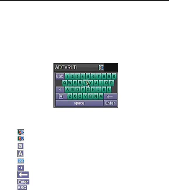
When a mouse is used to perform tasks on the TVR, clicking on a text input field will bring up the On-Screen Keyboard, shown in Figure 1-5.
Figure 1-5 On-Screen Keyboard
The buttons on the on-screen keyboard represent:
Lowercase: Designates lowercase input is being used.
Uppercase: Designates uppercase input is being used.
Switch to Lowercase: Switch to lowercase input.
Switch to Uppercase: Switch to uppercase input.
Number: Designates number input is being used.
Symbols: Switch to symbols input.
Backspace: Delete the character in front of the cursor.
Enter: Confirm selection.
ESC: Exit out of On-Screen Keyboard.
Figure 1-6 On-Screen Keyboard Buttons
1.9 Rear Panel Diagram
Example for illustration: TVRLT16XXX
6 |
TVR-LT User Manual & Web Client Guide V2.50 |

1 Introduction
Figure 1-7 Rear Panel Diagram
No. Item |
Description |
1Main VIDEO OUT BNC connector for video output and menu display. SPOT VIDEO OUT BNC connector for spot monitor. Single window view.
2VIDEO IN BNC connectors for analog video input.
3 |
VGA |
VGA output. Display local video output and menu. |
4 |
RS232 |
DB9 connector for RS232. |
5LAN Interface Connector for LAN (Local Area Network).
6AUDIO IN RCA connectors for analog audio input.
7USB Interface Connector for USB devices.
8 |
AUDIO OUT |
RCA connector for audio output. This connector is synchronized with |
|
VIDEO OUT. |
|||
|
|
||
9 |
RS-485 Interface |
Connector for RS-485 devices. T+, T- pin connects to PTZ. |
|
Connector for KB devices. D+, D- pin connects to special keyboard. |
|||
|
|
||
10 |
Loop Out Switch |
DIP switches for Loop Out. Switch on when a monitor is connected |
|
via the Video Loop Out interface. Switch off when no monitor is |
|||
|
|
connected via the Video Loop Out interface. |
11ALARM IN Connector for alarm input.
12Video LOOP OUT 16-ch DB15 connector for video loop out
13ALARM OUT Connector for alarm output.
14GROUND Ground(needs to be connected at DVR startup)
15 |
POWER |
AC 100~240V |
16 |
Switch |
Turn the device on/off |
Please note that VGA and Main Video Out support menu display but they are exclusive:
Monitors Connected during |
VGA Output |
CVBS1 Output |
TVR-LT Boot |
|
|
None Connected |
No output |
Main Monitor with Menu |
Composite CVBS1 only |
No output |
Main Monitor with Menu |
VGA only |
Main Monitor with Menu |
No output |
Both Connected |
Main Monitor with Menu |
No output |
7
2 Getting Started
Chapter 2 Getting Started
2.1Starting and Shutting Down Your TVR
Proper startup and shutdown procedures are crucial to extending the life of your TVR-LT.
To start up the TVR-LT:
1.Ensure the power supply is plugged into an electrical outlet. It is highly recommended that an Uninterruptible Power Supply (UPS) is used in conjunction with the unit.
2.Turn on the switch on the rear panel
3.After startup, the Status indicator LED will remain green.
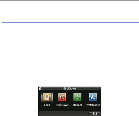
There are two ways to shut down the TVR-LT:
OPTION 1: via Shutdown menu
1. Enter the Shutdown menu shown in Figure 2-1 by clicking on Menu > Shutdown.
Figure 2-1 Shutdown Menu
2.Select the Shutdown button.
3.Click “Yes” to the message “Are you sure to turn off TVR-LT?”
4.Turn off the switch on the rear panel.
OPTION 2: Manual Shutdown
1.Press and hold the POWER button for 3 seconds.
2.Enter the administrator username and password in the dialog box for authentication.
3.Click the Yes button.
4.Message “Are you sure to turn off TVR-LT?” will open.
5.Click “Yes” then the message “Shutting down” will open.
6.Turn off the switch on the rear panel.
2.2Rebooting and Locking Your TVR-LT
While in the Shutdown menu (Figure 2-1), you may also reboot or lock your TVR-LT. Locking your TVR-LT will return you to the Live Preview mode, which will require a user name and password to exit. Pressing the Reboot button will reboot your TVR-LT.
To reboot or lock the TVR-LT:
1. Enter the Shutdown menu by clicking Menu > Shutdown.
8 |
TVR-LT User Manual & Web Client Guide V2.50 |
2 Getting Started
2. Select the Lock button to lock the TVR-LT or the Reboot button to reboot it.
2.3 Switch user
While in the Shutdown menu (Figure 2-1), you may also switch user account to access different operation privileges of the TVR-LT.
To switch user:
1.Enter the Shutdown menu by clicking Menu > Switch user.
2.Click Switch User button and enter the new username and password in the dialog box for authentication.
3.Click Yes.
2.4Using the Setup Wizard
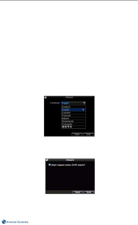
By default, the Setup Wizard will start once the TVR-LT has loaded, as shown in Figure 2-2. The Setup Wizard will guide you through some of the common settings of your TVR-LT.
The first step is language selection. The GUI language is English by default, however, other listed languages are available. Click Cancel to skip this step and use the default language.
Figure 2-2 Language Selection
The Setup Wizard will then guide you to other settings.
If you do not wish to use the Setup Wizard at this time, click Cancel. You may also choose to use the Setup Wizard at a later time by leaving the “Start Wizard when DVR starts?” checkbox selected.
Figure 2-3 Setup Wizard
To start using the Setup Wizard:
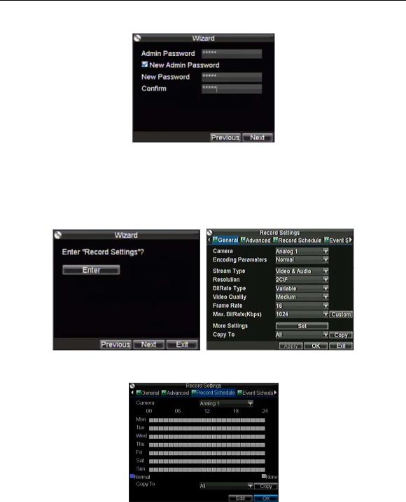
1.Click Next on the Wizard window. This will take you to the User Permission window, shown in Figure 2-4.
9
2 Getting Started
Figure 2-4 User Permission
2.Navigate to the Admin Password input field.
3.Enter the admin password (12345 by default).
4.To change the admin password, select New Admin Password checkbox. Enter the new password and confirm it in the respective fields.
5.Click Next. This will take you to the Record Settings window, as shown in Figure 2-5.
6.To configure Record Settings, click Enter.
Figure 2-5 Record Settings
7. Select the Record Schedule tab, shown in Figure 2-6.
Figure 2-6 Normal Schedule Settings
8.Click Edit. This will open up a new recording schedule, shown in Figure 2-7.
9.Select both the Enable Schedule and All Day checkbox. This will enable the recording schedule and have it record continuously all day.
10 |
TVR-LT User Manual & Web Client Guide V2.50 |
2 Getting Started
Figure 2-7 Edit Schedule Settings
10.Click OK. This will take you back to the Schedule tab. You can also copy the edited schedule to another channel or all of the other channels selected from the drop-down menu in the ‘Copy To’ field.
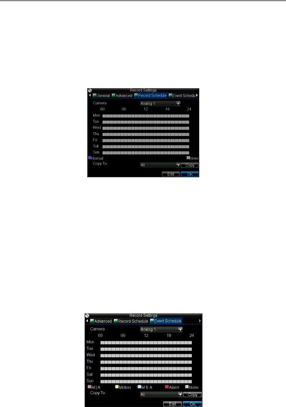
11.Select the Event Schedule tab, shown in Figure 2-8.
Figure 2-8 Event schedule Settings
12.Click Edit. This will open up a new recording schedule, shown in Figure 2-9.
13.Select both the Enable Schedule and All Day checkbox. This will enable the event recording schedule and have it record continuously all day. Choose event Type from the drop down list of available events.
Figure 2-9 Edit Event Schedule Settings
14.Click OK. This will take you back to the Schedule tab. You can also copy the edited schedule to another channel or all of the other channels selected from the drop-down menu in the ‘Copy To’ field.
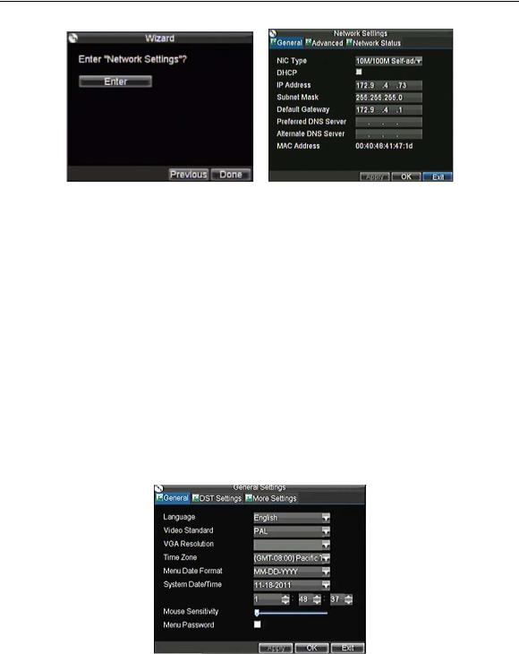
15.Click Next. This will take you to the Network Settings window, shown in Figure 2-10.
11
2 Getting Started
Figure 2-10 Network Settings
16.To configure network parameters, click Enter.
17.Enter the IP Address, Subnet Mask and Default Gateway.
18.Click OK to return to the Setup Wizard.
19.When all the settings are finished as desired, click Done to exit the Setup Wizard.
2.5 Setting Date & Time
It is extremely important to set up the system date and time correctly in order to timestamp recordings and events accurately.
To set up date and time:
1.Open the Menu window by clicking the MENU button on the IR remote control or the front panel of your TVR-LT. You can also go to the Menu window by right-clicking with the mouse and clicking Menu.
2.Click the Settings icon.
3.Select the General tab. You will be taken to the General Settings window, as shown in Figure 2- 11.
Figure 2-11 General Settings
4.Enter the correct date and time under System Date/Time, and choose Time Zone according to your actual region.
5.Click Apply to save the settings.
6.In addition, NTP can be applied to synchronize date/time automatically with an Internet time server. Please refer to Section 8.4 Configuring an NTP Server.
12 |
TVR-LT User Manual & Web Client Guide V2.50 |

2 Getting Started
Figure 2-12 NTP Settings
13

3 Live Preview
Chapter 3 Live Preview
3.1 Live Preview
The Live Preview mode is automatically started after the TVR-LT boots up. It is also at the top of the menu hierarchy, and thus hitting the ESC key multiple times (depending on which menu you are in) will bring you to the Live Preview mode.
3.2 Understanding Live Preview Icons
There are two icons on each display in Live Preview mode to indicate the camera status. They are:
Event Icon: Indicates video loss or tampering, motion detection and/or sensor alarm.
Recording Icon: Indicates the current channel is recording. The recording may have been started from a schedule and/or triggered by motion or alarm.
3.3 Live Preview Related Operations
In Live Preview mode, you can:
1.Display Single Camera:
•Using the Front Panel/Remote: Use Alphanumeric buttons.
•Using the Mouse: Select Single Camera in the right-click menu.
2.Preview Layout Switch:
•Using the Front Panel/Remote: Click PREV button.
•Using the Mouse: Select Multi-Camera in the right-click menu.
3.Manual Switch:
•Using the Front Panel/ Remote Control: To move to the previous screen, click the Left
direction button. To move to the next screen, click the Right direction button.
•Using the Mouse: Select Next screen in right-click menu.
4.Auto Switch:
•Using the Front Panel/Remote Control: Click the ENTER button.
•Using the Mouse: Select Start Sequence in the right-click menu.
5.Digital Zoom:
•Using the Mouse: Select Digital Zoom in the right-click menu.
3.4 Using the Mouse in Live Preview
Many features of the Live Preview can be quickly accessed by clicking the right-button of the
14 |
TVR-LT User Manual & Web Client Guide V2.50 |
3 Live Preview
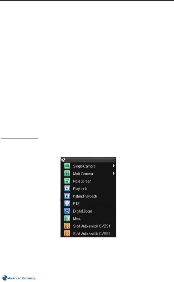
mouse (shown in Figure 3-1). These features include:
•Single Camera: Switch to a full screen display of the selected camera. The required camera is selected from a drop down list.
•Multi-Camera: Switch between different display layout options. Layout options can be selected from a drop down list.
•Next Screen: When displaying less than the maximum number of cameras in Live Preview, clicking this feature will switch to the next set of displays.
•Playback: Enter Playback mode.
•Instant Playback: Enter Instant Playback mode, the selected camera will be played from the earliest video of the day.
•PTZ: Enter PTZ Control mode.
•Digital Zoom: Enter the Digital Zoom interface.
•Menu: Enter Main menu.
•Start VGA/CVBS1 Auto-switch: Enable sequencing in Live Preview mode.
•Start CVBS2 Auto-switch: Enable sequencing in Live Preview mode.
Note
The dwell time should be set in Preview Settings before using Start Auto-switch.
If some cameras are to be skipped in sequenced live view, those cameras can be marked with an ‘X’ and they will not be displayed, please refer to Chapter 3.7
Figure 3-1 Live Preview Mouse Menu
15
3 Live Preview
3.5 Using Digital Zoom
To use digital Zoom in Live Preview mode:
1.Right-click using the mouse in Live Preview mode.
2.Select Digital Zoom from the Mouse menu.
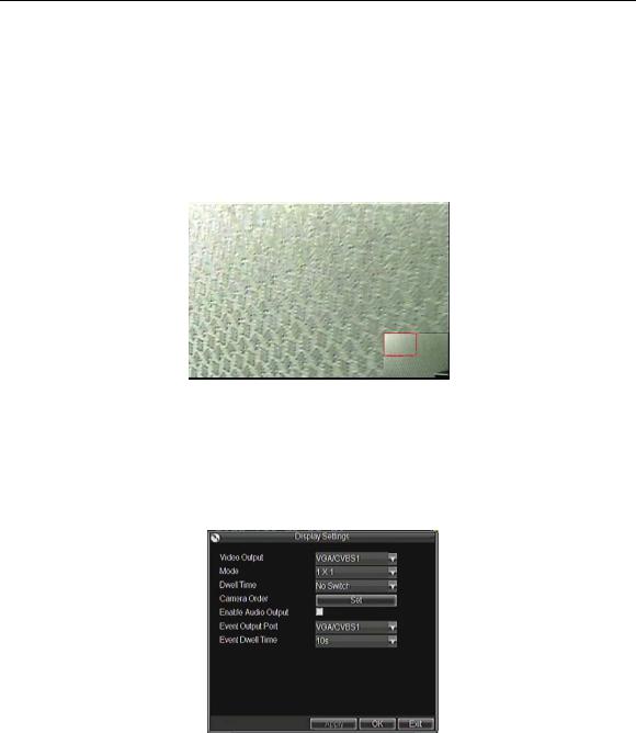
3.Click and drag the red box to the desired area to zoom. The zoomed image will be magnified by 4x. A sample of this can be seen in Figure 3-2.
Figure 3-2 Digital Zoom
3.6 Configuring Live Preview Displays
Live Preview displays can be customized to your own needs. These settings can be accessed by entering the Display Settings menu.
Figure 3-3 Display Settings
To access the Display Settings menu:
1.Click the MENU button.
2.Click the Settings icon.
3.Click the Display icon.
The settings available in this menu include:
•Video Output: Designates the output to be configured. Outputs include Main Vout and Spot Vout.
•Mode: Designates the display mode to be used for Live Preview (Spot out single pane only).
•Dwell Time: The time in seconds to dwell between switching of channels when Start Auto-switch is selected in Live Preview.
•Camera Order: The order of the cameras to be used in the selected display mode (See
16 |
TVR-LT User Manual & Web Client Guide V2.50 |
3 Live Preview
Setting Camera Order).
•Enable Audio Output: Enable/disable audio output for the selected video output.
•Event Output Port: Designates the output to show event video.
•Event Dwell Time: The time in seconds to show an event on-screen.
3.7 Setting Camera Order
Setting the camera order allows you to logically position cameras for more efficient monitoring of a location.
Note
Spot video out does not support screen division.
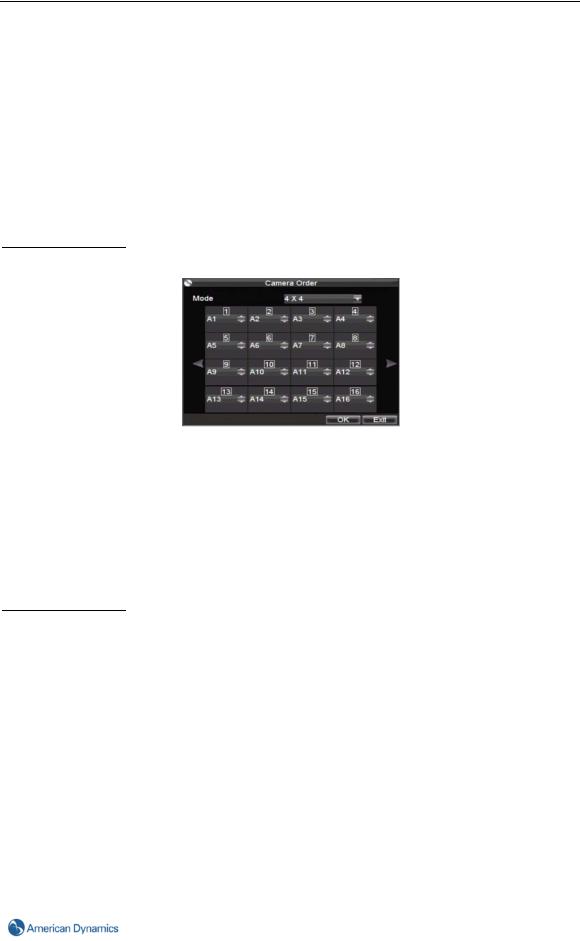
Figure 3-4 Camera Order Setting
To set the camera order:
1.Enter the Display Settings menu, shown in Figure 3-4 (Menu > Settings > Display).
2.Click Set next to Camera Order.
3.Select the display mode you would like to set the camera order for under Mode.
4.Using the up and down button at each display, select the camera you would like to set. Setting an ‘X’ means the camera will not be displayed.
5.Click OK to save live view layout and exit.
Note
Duplicate cameras are not allowed in the camera order.
17
4 Record Settings
Chapter 4 Recording Settings
4.1 Configuring Recording Parameters
There are multiple ways to setup your TVR-LT for recording. They include setting up a recording schedule, triggering a recording by motion detection and/or a sensor alarm.
4.1.1 Initializing Record Settings
Before setting your TVR-LT up for recording, certain parameters should be configured first. The steps to configure these parameters are:
1.If you have not initialized a HDD either through the Setup Wizard or through HDD management, you must do so before proceeding.
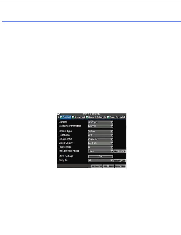
2.Navigate to Menu > Settings > Record. You will be taken to the Record Settings menu, shown in Figure 4-1.
Figure 4-1 General Record Settings
3.Select the camera you would like to configure the settings for.
4.Configure settings for:
•Encoding Parameters: Select the encoding parameters, either Normal or Event.
•Stream Type: Type of stream to record, either video or video & audio.
•Resolution: Select the resolution of the recording. The options include 4CIF, 2CIF, CIF and QCIF.
•Bit Rate Type: Select either Variable or Constant bit rate.
•Video Quality: Select the quality of the recording.
•Frame Rate: Select the frame rate for the recording.
•Max Bit Rate: Select or define custom maximum bit rate for recordings.
Note
When Stream Type is set to Video & Audio, the user must also enable the Record Audio option as shown in Point 5 below.
TVR-LT supports dual stream technology, which includes Main and Sub-streams. Both Normal and Event encoding parameters are Main stream type. Sub-stream may only be set via the TVR Remote Client or Web Client .
5.Click the Set button under More Settings. This will bring up another menu with further advanced recording options, as shown in Figure 4-2.
18 |
TVR-LT User Manual & Web Client Guide V2.50 |
4 Record Settings
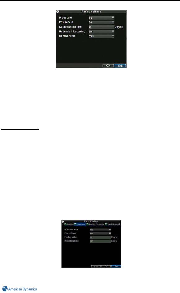
Figure 4-2 Additional Record Settings
6.Set additional Record Settings:
• Pre-Record: Sets the time in seconds to record before the actual recording begins.
Please note the pre-record time cannot be guaranteed. This will largely depend on the bit rate.
•Post-Record: Sets the time in seconds to record after the actual event has ended.
•Data retention time: Sets the expiration time in days (0-31) for recorded video. Recordings prior to this time are deleted. Setting the value to ‘0’ disables this feature.
•Redundant Record: Enable or disable redundant recording on a particular channel.
•Record Audio: Enable or disable the recording of audio in addition to video.
Note
The Record Audio option is only available when the Stream Type is set to Video & Audio.
7.Click OK to finish and return to the previous menu.
8.Select the Advanced tab and this will open the Advanced settings menu, shown in Figure 4-3.
• HDD Overwrite: Enable or disable the HDD Overwrite setting. Enabling the Overwrite setting
will cause recorded files to be overwritten once the HDD is full.
•Export Player: To include a basic version of the TVR Player with the exported video file, select [YES], otherwise set this option to [NO]. The exported version will only play proprietary TVR MP4 files, whereas the full version of the TVR Player included on the CD supplied with the device will also play converted AVI files, compatible with Windows Media Player and Quick Time.
•Existing Video (Days): This indicates how many days’ video is currently stored on the hard
drive.
Recording Time (Days): An estimate of how many days of video can be recorded and stored on the HDD, based on dynamic changes to recording settings and historical recording behavior.
9. Click Apply and then OK.
Figure 4-3 Advanced Record Settings
19
4 Record Settings
4.1.2 Scheduling a Recording
Scheduling a recording allows you to set up the TVR-LT to record only at certain times. There are two schedules for both Normal record and Event record.
To setup a normal recording schedule:
1.Enter the Record Settings menu (Menu > Settings > Record).
2.Select the Record Schedule tab to open the Schedule menu, shown in Figure 4-4.
Figure 4-4 Record Schedule Settings
3.Select the Camera to edit the schedule for.
4.Click Edit.
5.Select the Enable Schedule checkbox.
6.Select the day you would like to set up the schedule for or select All Week to record the entire week.
7.To record the entire day, check All Day, otherwise configure selected time periods only. Up to 8 time periods can be scheduled. It is important to note that time periods cannot overlap.
8.Click OK to finish configuration.
9.Repeat steps 3-9 for other cameras or copy settings from one schedule to the next under the Copy To section.
10.Click OK to finish and save the schedule settings.
To set up an event recording schedule:
1.Enter the Record Settings menu (Menu > Settings > Record).
2.Select the Event Schedule tab to open the Schedule menu, shown in Figure 4-5.
Figure 4-5 Event Schedule Settings
5.Select Camera to edit schedule for.
6.Click Edit.
20 |
TVR-LT User Manual & Web Client Guide V2.50 |
Loading...