


AD1024
Table of contents
 Loading...
Model AD1024
MegaPower II
Matrix Switching Bays
Installation and Operating Instructions
This manual describes the installation and operating procedures for the American Dynamics model AD1024 Matrix Switching
System Bays. The AD1024 MegaPower II is designed as an integrated matrix switching and control system for CCTV
surveillance systems having multiple cameras, multiple monitors, and multiple control stations. The AD1024 Systems consist of
a matrix switching bay, its power supply module, a data receiver/buffer module, the required video input modules (VIM), video
output modules (VOM), and appropriate rear panels.

This software/firmware is confidential to and is copyrighted by SENSORMATIC ELECTRONICS CORPORATION. It is not to
be copied or disclosed in any manner without the express written consent of SENSORMATIC. The software is furnished to the
purchaser under a license for use on a single system.
NOTE: Information furnished by SENSORMATIC is believed to be accurate and reliable. However, no responsibility is assumed
by SENSORMATIC for its use; nor for any infringements of other rights of third parties which may result from its use. No
license is granted by implications or otherwise under any patent or patent rights of SENSORMATIC.
Copyright 1999 by SENSORMATIC. All rights reserved.
The installation of this product should be made by qualified
service personnel and should conform to all local codes.
QA301D
!
WW
WW
AA
AA
RR
RR
NN
NN
II
II
NN
NN
GG
GG
To reduce the risk of fire or shock hazard, do
not expose this product to rain or moisture.
AMERICAN
DYNAMICS
CAUTION: TO REDUCE THE RISK OF ELECTRIC SHOCK,
DO NOT REMOVE COVERS (OR BACK) .
NO USER-SERVICEABLE PARTS INSIDE.
REFER SERVICING TO QUALIFIED SERVICE PERSONNEL
RISK OF ELECTRIC SHOCK
DO NOT OPEN
CAUTION
!
The lightning flash with arrowhead
symbol, within an equilateral
triangle, is intended to alert the
user to the presence of uninsulated
"dangerous voltage" within the
product's enclosure that may be of
sufficient magnitude to constitute a
risk of electric shock to persons.
The exclamation point within an
equilateral triangle is intended to
alert the user to the presence of
important operating and maintenance
(servicing) instructions in the
literature accompanying the product.
UU
UU
NN
NN
PP
PP
AA
AA
CC
CC
KK
KK
II
II
NN
NN
GG
GG
AA
AA
NN
NN
DD
DD
II
II
NN
NN
SS
SS
PP
PP
EE
EE
CC
CC
TT
TT
II
II
OO
OO
NN
NN
Unpack carefully. This is an electronic product and should
be handled as such. Compare the items received with the
packing list with your order.
Be sure to save:
1. The shipping cartons and insert pieces. They are the )
safest material in which to make future shipments of
the product.
2. The IMPORTANT SAFEGUARDS sheet.
3. These Installation and Operating Instructions.
MM
MM
AA
AA
II
II
NN
NN
TT
TT
EE
EE
NN
NN
AA
AA
NN
NN
CC
CC
EE
EE
User maintenance of this unit is limited to external cleaning
and inspection. For specific recommendations refer to the
IMPORTANT SAFEGUARDS sheet packaged with this product.
II
II
NN
NN
SS
SS
TT
TT
AA
AA
LL
LL
LL
LL
AA
AA
TT
TT
II
II
OO
OO
NN
NN
AA
AA
NN
NN
DD
DD
SS
SS
EE
EE
RR
RR
VV
VV
II
II
CC
CC
EE
EE
If you require information during installation of this
product or if service seems necessary, contact the
Sensormatic Repair and Service Department at (800)
442-2225. You must obtain a Return Authorization Number
and shipping instructions before returning any product for
service.
Do not attempt to service this product yourself. Opening or
removing covers may expose you to dangerous voltages or
other hazards. Refer all servicing to qualified personnel.
This equipment has been tested and
found to comply with Part 15 of the
FCC Rules.
Operation is subject to the
following two conditions: 1. This
device may not cause harmful
interference, and 2. This device
must accept any interference
received, including interference
that may cause undesired operation.


CONTENTS
Page
General Description.........................................................................1
System Modules Description
Power Supply Module 2010PS..................................................2
Data Buffer Module 2010DB.....................................................4
Video Loss Detection Data Buffer 2010DBVL.........................6
Video Input Module 2016AVIM................................................8
Video Output Module 2024VOM..............................................9
Master Date Time Module 2024MDT.....................................10
Installation
Power Sources..........................................................................11
Mounting..................................................................................11
Connections..............................................................................11
Setup
Data Buffer Module.................................................................12
Video Loss Detector Data Buffer.............................................13
Video Input Module.................................................................14
Video Output Module ..............................................................16
Power Supply Module..............................................................18
Powering Up
Powering the Matrix Bay.........................................................19

CONTENTS
Page
System Configurations
Level 1 Systems
Level 1 - 256 X 16, One Bay with No Titles.....................20
Level 1 - 192 X 16, One Bay System ................................21
Level 1 - 448 X 16, Two Bay System................................22
Level 1 - 704 X 16, Three Bay System..............................23
Level 1 - 960 X 16, Four Bay System ...............................24
Level 1 - 1024 X 16, Five Bay System..............................25
Level 2 Systems
Level 2 - 64 X 32, One Bay System ..................................27
Level 2 - 192 X 32, Two Bay System................................28
Level 2 - 320 X 32, Three Bay System..............................29
Level 2 - 448 X 32, Four Bay System ...............................30
Level 2 - 704 X 32, Six Bay System..................................31
Level 2 - 960 X 32, Eight Bay System ..............................32
Level 2 - 1024 X 32, Nine Bay System.............................34
Level 3 Systems
Level 3 - 192 X 48, Three Bay System..............................36
Level 3 - 256 X 48, Four Bay System ...............................37
Level 3 - 448 X 48, Six Bay System..................................38
Level 3 - 512 X 48, Seven Bay System.............................39
Level 3 - 704 X 48, Nine Bay System...............................40
Level 3 - 768 X 48, Ten Bay System.................................42
Level 3 - 960 X 48, Twelve Bay System ...........................44
Level 3 - 1024 X 48, Fourteen Bay System.......................46
ADULP Looping Panel............................................................48
Appendix
Level 1 Interconnect Drawings.......................................A1 - A5
Level 2 Interconnect Drawings.....................................A6 - A11
Level 3 Interconnect Drawings...................................A12 - A16
Level 8 Interconnect Drawings.............................................A17
Video Loss Detector Connections...............................A18 - A21
Video Buffer Interconnection................................................A22

GENERAL DESCRIPTION
The MegaPower II AD1024 Switcher/Control System is an
integrated matrix switching and control system for CCTV
surveillance systems. It is capable of controlling up to 1024
video input sources such as cameras, and 128 video outputs
such as monitors and video tape recorders.
The AD1024 system consists of a matrix switching bay, its
power supply module, a data receiver/buffer module, the
required video input modules (VIM), video output modules
(VOM), and appropriate rear panels. All AD1024 systems are
controlled with a separate central processing unit (CPU) and
keyboard.
AD1024 Switcher/Control Systems are supplied as completely
configured switching bays. Only the bay interconnections, the
CPU connections, the video input and output connections, and
any optional accessory connections need be made prior to
operation. The AD1024 system, as delivered, is a complete
system with all inputs terminated in 75 ohms. Each bay is
packed in a separate shipping carton labeled with the AD1024
bay assembly number on the outside of the carton.
Matrix Switching Bay
The 2010R and 2020R switching bays include the physical
chassis, a back plane, a power supply module, and a data
receiver. Each bay has the capability of looping the DATA
LINE input and looping an external vertical synchronization
pulse to other bays. Each bay also accommodates a
combination of video input modules and video output modules,
up to a total of 16 modules.
Power: 50 watts (full system)
Size: 10-1/2” height. Full-width 19” rack mount
Weight: 60 lbs. (28 kg) (full system)
CPU (Central Processing Unit)
The CPU for the AD1024 system is a separate rack-mounted
unit that includes its own power supply, system software, ten
RS-232 ports, a system diagnostic monitor output, and two
DATA LINE outputs. These DATA LINE outputs distribute
high speed data control signals to the AD1024 matrix
switching bays and optional accessories.
AD1024 Central Processing Unit
Power: 4 watts
Size: 1.75” height. Full-width 19” rack mount
Weight: 10 lbs. (4.5 kg)
OPTIONAL EQUIPMENT
The following separate units may be connected to the AD1024
system for added capabilities. For specific information, refer
to the respective data sheets.
2091 Control Code Generator/Distributor
The 2091 provides 64 control-code outputs for control of 1640
and 1680 Series Receivers actuating pan/tilt; lens zoom, focus,
and iris; and auxiliaries at suitably-equipped camera sites.
2031 Switcher/Follower,
2032 Alarm Responder,
2033 Auxiliary Follower
The 2030 Series Followers switch external circuits when
designated cameras are called to designated monitors (2031),
when designated monitors are in alarm conditions (2032), or
when designated auxiliaries are called up or designated
cameras are alarmed (2033).
ADULP Looping Panel
The ADULP Looping Panel is used to facilitate the looping of
video signals for the AD1024 system from external inputs or to
external devices such as time-lapse video recorders, switchers,
monitors, etc.
Other Switcher/Control System Accessories
• 1640 and 1680 Series Receivers
• 1670 and 2078 Series Keyboards
• 1680MG Manchester Generator
• 1683 Control Code/PSK Modem
• 1981 Port Expander
• 2081 Port Expander
• 1983 Code Converter
• 2083 Code Translators
• 2096 Alarm Interface Unit
• 1985A Hot Switch
This installation should be made by qualified service personnel
and should conform to all local codes. Safeguards must be
taken to avoid unintentional operation by employees and
maintenance personnel working about the premises, by falling
objects, by customers, by building vibration, and by similar
causes.
1
GENERAL DESCRIPTION
IF YOU ENCOUNTER ANY PROBLEMS
OPERATING THIS UNIT, OR NEED ASSISTANCE,
CALL OUR TECHNICAL SUPPORT CENTER AT:
within the United States: 1-800-442-2225
outside the United States: (845) 624-7600
SYSTEM MODULES
The following pages describe the plug-in modules available for
AD1024 switching bays. These include:
Power Supply Module, 2010PS
Data Buffer Module, 2010DB
Video Loss Detection Data Buffer Module, 2010DBVL
Video Input Module, 2016AVIM
Video Output Module, 2024VOM
Master Date Time Module, 2024MDT
Power Supply Module - 2010PS
The power supply module for the matrix switching bay
converts AC power to the necessary DC voltages which are
supplied to all the modules in the switching bay.
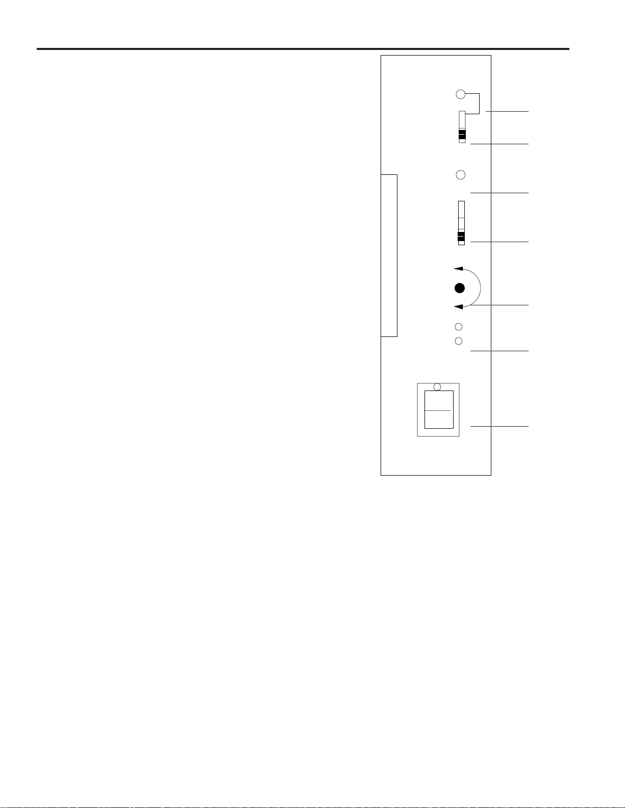
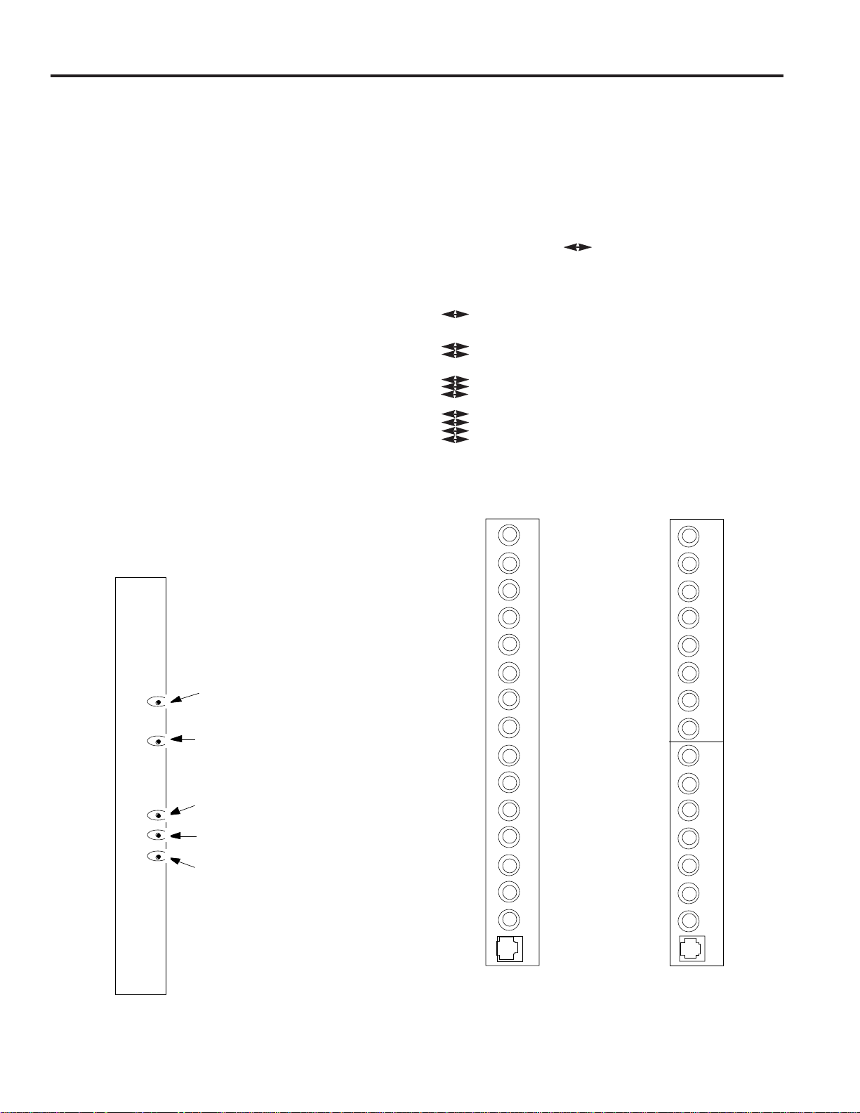
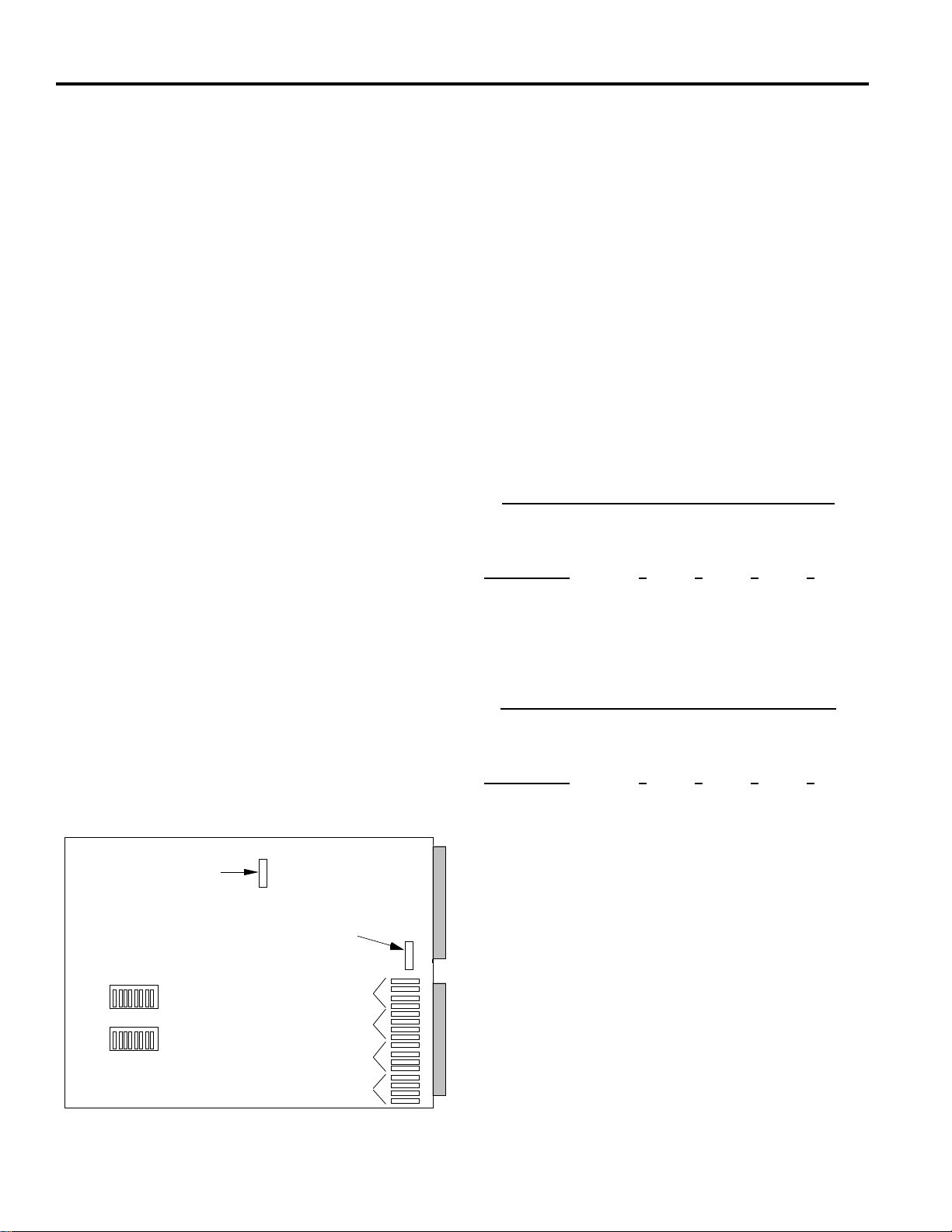
Front Panel
Figure 1 illustrates the features described below.
1- SYNC TEST ON/OFF LED: This red LED is illuminated
when the SET UP/NORMAL switch (below) is in the SET
UP position.
2- SET UP/NORMAL SWITCH: When set to the SET UP
position, this switch implements sync test and adjustment.
(See Power Supply Setup, page 18.)
3- SYNC LOSS LED: This red LED is off if video sync is
locked. When illuminated, it indicates that sync is not
locked due either to a poor sync signal, no sync signal, or
the wrong sync signal (as determined by the setting of the
sync selection switch below).
4- SYNC REFERENCE SELECTION SWITCH: This
switch selects one of three video sync references:
EXT V-DRIVE (Up position): Selects the external vertical
drive pulse input on the rear panel (EXT SYNC IN).
EXT CAM (Center position): Selects composite video.
AC LINE (Down position): Selects the AC line (as
supplied).
5- SYNC PHASE ADJUSTMENT: This potentiometer,
accessed thru the hole in the front panel of the Power
Supply, adjusts the phase of the sync pulse with respect to
the selected reference. When the sync test switch is set to
SET UP, a horizontal trace line is displayed on Monitor 1,
showing the location of the sync pulse with respect to the
picture. (See Power Supply Setup, page 18.)
6- +9 VDC AND -9 VDC LED's: These green LED's, when
illuminated, indicate the presence of DC voltages (Note: For
the 230 VAC systems, the output voltages are +/-8 VDC).
7- POWER ON/OFF SWITCH: This switch is used to apply
power to the bay. When the switch is in the ON position, a
green light is illuminated behind the Power On/Off Switch.
Fusing: Four replaceable fuses are located on the power
supply circuit board. Replacement fuses must meet national
and local use code requirements.
Fuse Ratings:
For 120VAC Systems:
F1: 125V, 5 AMP, 5 x 20 mm
F2: 125V, 5 AMP, 5 x 20 mm
F3: 250V, SB, 0.5 AMP, 5 x 20 mm, UL listed
F4: 250V, SB, 0.5 AMP, 5 x 20 mm, UL listed
For 230VAC CE Compliant Systems:
F1: 250V, T, 3.15 AMP, 5 x 20 mm
F2: 250V, T, 3.15 AMP, 5 x 20 mm
For 230VAC Non-CE Compliant Systems:
F1: 125V, 5 AMP, 5 x 20 mm
F2: 125V, 5 AMP, 5 x 20 mm
F3: 250V, T, 0.25 AMP, 5 x20 mm
F4: 250V, T, 0.25 AMP, 5 x 20 mm
SYSTEM MODULES DESCRIPTION
Figure 1 - Front Panel of Power Supply Module
SET UP
NORMAL
EXT V-DRIVE
EXT CAM
AC LINE
PHASE
+9VDC
-9VDC
SYNC
LOSS
1
2
3
4
5
6
7
2
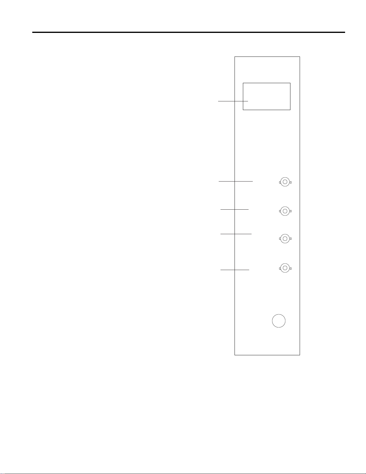
Power Supply Module - Rear Panel
Figure 2 is the illustration associated with the features
described below.
8- SERIAL # TAG: Serial number assigned to this AD1024
switching bay.
9- DATA LINE IN: Input for DATA LINE.
10- DATA LINE OUT: Looping output for DATA LINE.
This line must be terminated with a 75-ohm terminator.
11- EXTERNAL SYNC IN: Input for external vertical
synchronous pulse, either camera sync or an externally
created sync pulse.
12- EXTERNAL SYNC OUT: Looping output for EXT
SYNC. This line must be terminated with a 75-ohm
terminator.
3
SYSTEM MODULES DESCRIPTION
Model: AD2010
S/N: XXXXX
IN
DATA LINE
OUT
120 V
60 Hz
IN
EXT
SYNC
OUT
Figure 2 - Rear Panel of Power Supply Module
8
9
10
11
12
Data Buffer Module - 2010DB
The Data Buffer Module serves a dual purpose. First, it
distributes switched video, from the bay's Video Input
Modules, to other bays in multiple bay systems. The video
observed from these outputs contain no character information,
only standard video.
The second purpose of the Data Buffer is to filter incoming
system information from the DATA LINE. Filtering is
performed to allow for the passage of localized information.
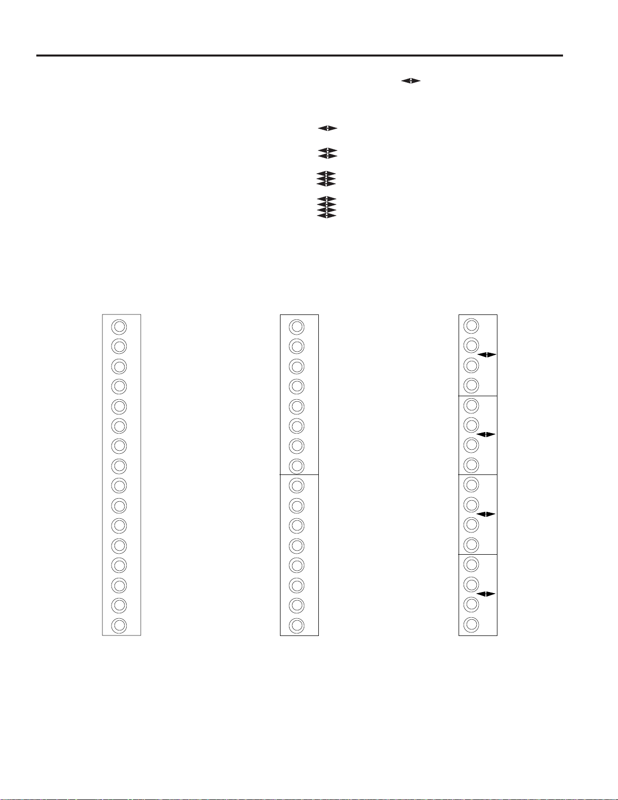
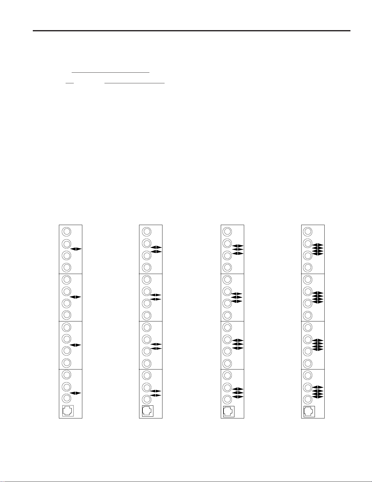
The 2010DB rear panel has 16 video output BNC's for
connection to Video Output Modules in other switching bays.
The illustrations in Figures 3 through 8 show the various types
of rear panels of the Data Buffer module.
See Appendix Figure A22 for illustration of interconnection
from these modules to the Video Output Modules.
Icon Definition: The is the video/interconnect symbol
for connecting switched video among the matrix switching
bays.
Switched video inputs from cameras 1 to 256.
Switched video inputs from cameras 257 to 512.
Switched video inputs from cameras 513 to 768.
Switched video inputs from cameras 769 to 1024.
Figure 3
2010DB-00
Rear Panel
Figure 4
2010DB-01
Rear Panel w/ 16 BNCs
Camera Card Bay
(No Monitor Modules)
Figure 5
2010DB-11 to 2010DB- 18
Rear Panel w/ 16 BNCs
Multiple-Bay System
for cameras 1-256
1
6
Output 16
8
1
Output 1
9
4
1
2
1
3
5
Output 8
4
SYSTEM MODULES DESCRIPTION
T
E
S
T
/
E
X
P
A
N
S
I
O
N
O
N
L
Y
16
Output 16
Output 8
8
1
Output 1
O
U
T
9
O
U
T

5
SYSTEM MODULES DESCRIPTION
1
6
Output 16
Output 8
8
1
Output 1
9
4
1
2
1
3
5
Data Buffer Module - 2010DB (continued)
1
6
Output 16
Output 8
8
1
Output 1
9
4
1
2
1
3
5
1
6
Output 16
Output 8
8
1
Output 1
9
4
1
2
1
3
5
Figure 6
2010DB-21 to 2010DB-28
Rear Panel w/ 16 BNCs
Multiple-Bay System
for cameras 257-512
Figure 7
2010DB-31 to 2010DB-38
Rear Panel w/ 16 BNCs
Multiple-Bay System
for cameras 513-768
Figure 8
2010DB-41 to 2010DB-48
Rear Panel w/ 16 BNCs
Multiple-Bay System
for cameras 769-1024
Video Loss Detection Data Buffer Module - 2010DBVL
The Video Loss Detector Data Buffer Module provides the
same capabilities as the 2010DB Data Buffer Module, with one
significant addition. First, it distributes switched input video,
with no character information, to multiple bay systems. It also
filters incoming information from the DATA LINE to allow for
the passage of localized information.
The additional function of this module is to detect the presence
of a video signal for each camera input. Each module can
detect video loss for a maximum of 256 cameras. For a full
matrix switching system of 1024 cameras, four 2010DBVL
modules are required, one for each block of 256 cameras.
The 2010DBVL module must be placed in the matrix
switching bay that is connected to the highest numbered
monitor output, and this bay must contain Video Input
Modules. The 2010DBVL cannot be used in a switching bay
that does not include Video Input Modules.
Front Panel
The front panel of the 2010DBVL provides indicator LED's
that illuminate if a video or sync loss is detected, and indicate
the SYNC and VIDEO content of the video input signal being
monitored. See Figure 9 for location of these LED's.
Rear Panels
The 2010DBVL rear panel has 15 video output BNC's for
connection to Video Output Modules, and one 8-pin, RJ45 RS-
232 connector for Video Loss Detection data output and Alarm
Contact output to an Alarm Interface Unit. Figures 9 through
15 show the various types of rear panels of the Video Loss
Detector Data Buffer module.
Icon Definition: The icons on the rear panels are the
video/interconnect symbol for connecting switched video
among the matrix switching bays.
Switched video inputs from cameras 1 to 256.
Switched video inputs from cameras 257 to 512.
Switched video inputs from cameras 513 to 768.
Switched video inputs from cameras 769 to 1024.
See Appendix Figure A22 for illustration of interconnection
from these modules to the Video Output Modules.
Figure 10
2010DBVL-00
Rear Panel
Figure 11
2010DBVL-01 Rear Panel
Camera Card Bay
(No Monitor Modules)
T
E
S
T
/
E
X
P
A
N
S
I
O
N
O
N
L
Y
SYSTEM MODULES DESCRIPTION
6
1
5
8
1
O
U
T
9
O
U
T
H
M
L
indicates Video or Sync Loss
indicates Sync present
indicates High video content
indicated Medium video content
indicates Low video content
VIDEO
LEVEL
ALARM
SYNC
Figure 9
2010DBVL Front Panel LED Indicators
When a video loss is detected, a video loss message is
transmitted from the 2010DBVL via the RJ45 connector RS-
232 pins. An alarm contact is also provided by pins 1 and 2 of
this connector. The connector pin definitions are as follows.
RJ45 Connector Pin Definitions
Pin Function (RS-232 Code)
1 Alarm Contact Output
2 Alarm Ground
4 Receive Data (RCD)
5 Transmit Data (XMIT)
7 Ground (GND)
The RS-232 pins are connected to an RS-232 port, on the
AD1024 CPU, which is set for VIDEO LOSS use. The RS-
232 port can be connected using the supplied modularcable. if
the distance between the 2010DBVL and the CPU is less than
7 feet.
If the distance exceeds 7 feet, or if the Alarm Contact output is
used, an 8-pin Terminal Box is provided for
connections. The Terminal Box is connected to the
2010DBVL RS-232 port with the supplied modular cable. The
maximum cable length between an RS-232 device and the
Terminal Box is 1000 feet, using 18-AWG shielded, computer
grade cable.
All American Dynamics equipment is configured as RS-232
DTE (Data Terminal Equipment) devices. For DTE-to-DTE
connection to the 2010DBVL Terminal Box:
- the XMIT pin of the 1996 port is connected to RCD (pin
4) of the 2010DBVL Terminal Box.
- the RCD pin of the 1996 port is connected to XMIT (pin
5) of the 2010DBVL Terminal Box.
- the Ground of the 1996 port is connected to GND (pin 7)
of the 2010DBVL Terminal Box.
Pins 1 and 2 provide a logic-level alarm closure, in accordance
with the Alarm Contact mode set for the module (see page 13).
These pins are connected to the alarm contact inputs of a 2096
Alarm Interface Unit, pin 1 to “A” input and pin 2 to ground.
Where multiple 2010DBVL modules are used, 1981 or 2081
port expanders are used to connect these modules to the
AD1024 CPU. The 2010DBVL-1x module must be connected
to port A of the 1981, 2010DBVL-2x to port B, 2010DBVL-3x
to port C, and 2010DBVL-4x to port D. Video loss detection
will not operate unless all modules are connected to the
AD1024 CPU.
Typical connections of the 2010DBVL module are illustrated
in the Appendix, Figures A18 to A21.
Figure 12
2010DBVL-11 to -18
Multiple-Bay System
for cameras 1-256
Figure 13
2010DBVL-21 to -28
Multiple-Bay System
for cameras 257-512
Figure 14
2010DBVL-31 to -38
Multiple-Bay System
for cameras 513-768
Figure 15
2010DBVL-41 to -48
Multiple-Bay System
for cameras 769-1024
SYSTEM MODULES DESCRIPTION
7
1
5
8
1
9
4
1
2
1
3
5
1
5
8
1
9
4
1
2
1
3
5
1
5
8
1
9
4
1
2
1
3
5
1
5
8
1
9
4
1
2
1
3
5
Video Input Modules - 2016AVIM
The 2016AVIM performs the actual video switching in the
AD1024 switching bay. Each module can switch any one of
16 video inputs to any video output, or multiple combinations
of video outputs, up to 16. The 16 video inputs to the module
are connected at the rear panel associated with the video input
module. The switched video outputs are provided to the Video
Output Modules and the Data Buffer Module in the bay.
There are four different types of rear panels, shown below.
Icon Definition: The following icon denotes video inputs.
The 2016AVIM-1, as seen in Figure 16, has 16 BNC
connectors for video inputs. The number next to each BNC
reflects the actual input numbers.
The 2016AVIM-2, as seen in Figure 17, has eight BNC
connectors for the upper group of eight video inputs and one
34-pin connector. The number next to the BNC reflects the
actual input numbers.
The third rear panel, 2016AVIM-3, as seen in Figure 18, has
eight BNC connectors for the lower group of eight cameras to
complete the larger group of 16 video inputs and two 34-pin
connectors. The number next to the BNC reflect the actual
input numbers.
The fourth type of rear panel, 2016AVIM-4, as seen in Figure
19, has only two 34-pin connectors. They are used for
expansion in multiple switching bay configurations.
Figure 16
2016AVIM-1
Figure 17
2016AVIM-2
1
6
Input 16
Input 8
8
1
Input 1
9
4
1
2
1
3
5
8
1
O
U
T
SYSTEM MODULES DESCRIPTION
8
16
9
O
U
T
I
N
Figure 18
2016AVIM-3
Figure 19
2016AVIM-4
16
1
O
U
T
I
N
Video Output Module - 2024VOM
The 2024VOM (Video Output Module) creates the titles that
are added to the video output. Each module has four video
outputs on its rear panel.
Front Panel
Front panel controls on the Video Output Module adjust the
brightness, vertical, and horizontal position for each title
displayed on each of the four video outputs. The 4-position
rotary switch on the front panel governs which output you
control. The front panel LED blinks to verify proper operation
of the 2024VOM. See Figure 20 below. Further details on
operation of these controls is provided in the Video Output
Module SETUP description, page 17.
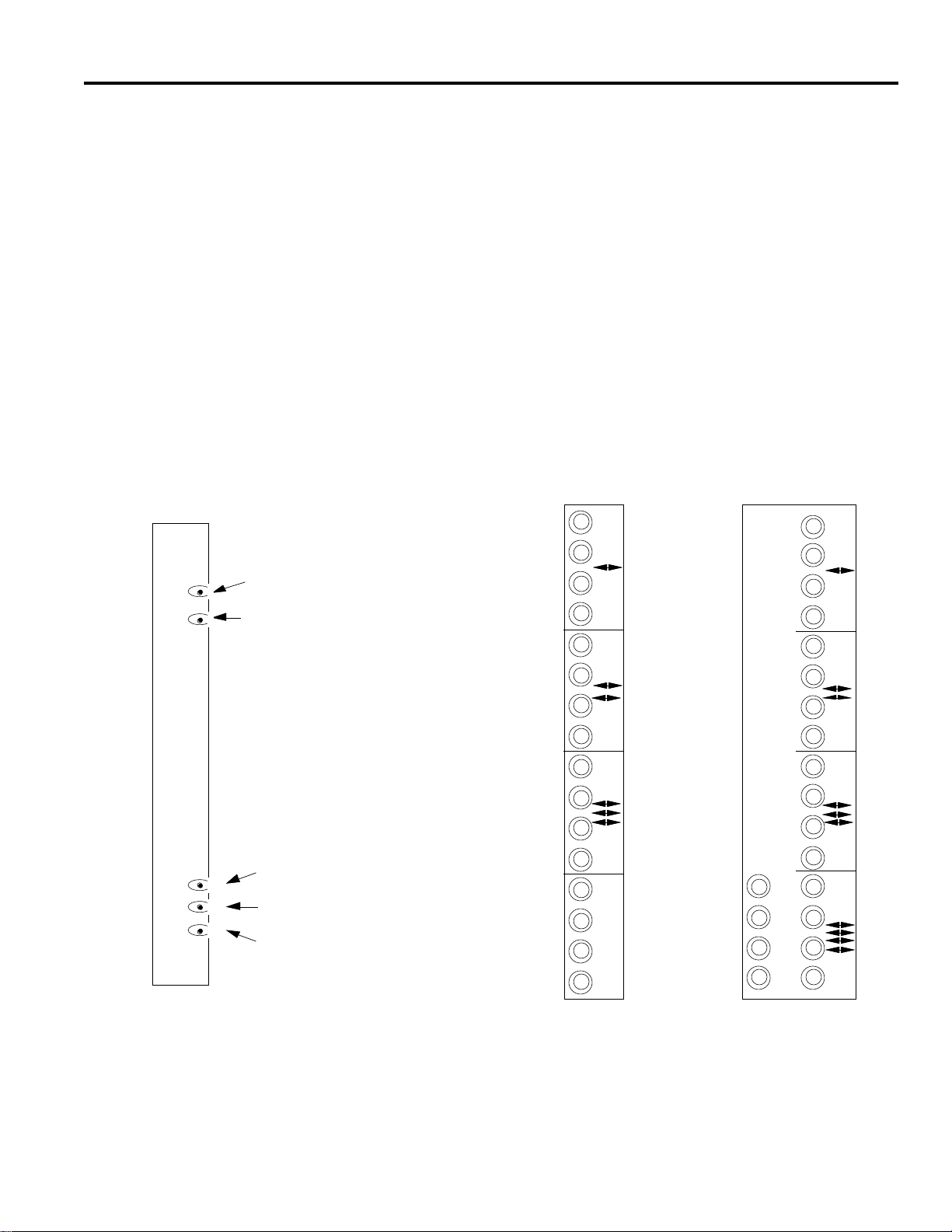
Rear Panels
The 2024VOM-1 rear panel, as seen in Figure 21, has 16 BNC
connectors. The bottom four BNCs are video outputs while
the remaining upper three groups, each containing four BNCs,
are for video inputs from other matrix switching bays in the
system.
The 2024VOM-2 rear panel, as seen in Figure 22, has four
sections of four BNCs for video inputs from other matrix
switching bays. A fifth section of four BNCs, in the lower left
corner, is used for video outputs.
9
SYSTEM MODULES DESCRIPTION
Figure 20
Video Output Module
Front Panel Indicators and Controls
H
V
B
A
D
.
.
Blinking LED for proper operation
4-position rotary switch
Horizontal control push button
Vertical control push button
Brightness control push button
Figure 21
Video Output Module
2024VOM-1
Rear Panel
Figure 22
Video Output Module
2024VOM-2
Rear Panel
1
4
4
1
1
4
1
4
O
U
T
O
U
T
1
4
1
4
4
1
1
4
1
4

Master Date Time Module - 2024MDT
The 2024MDT Master Date Time Module provides looping
connection of the video input signals and insertion of system
time and date information on the video output connections.
These modules are used with dedicated inputs for dedicated
outputs, and do not perform any inter-bay switching.
The 2024MDT has four looping video inputs and four separate
video outputs with system time and date information.
Front Panel
The 2024MDT front panel controls the brightness, vertical, and
horizontal position for each title displayed on each of the four
video outputs. The 4-position rotary switch governs which
output is selected for control. The LED blinks to verify proper
operation of the 2024MDT. The front panel controls operate
identical to those on the 2024VOM module, see Figure 20 on
page 9. Further details on operation of these controls is
provided in the Video Output Module SETUP description,
page 17.
Rear Panels
The 2024MDT rear panel, shown in Figure 23, has 12 BNC
connectors and handles four separate video input channels: A,
B, C, and D. The bottom four BNC's are video outputs which
contain time and date information from the system Data Line
interface. The upper four groups of BNC's are for video inputs
from matrix switching bays and looping outputs to other video
equipment, such as VCR's. Each BNC pair in the upper groups
is an unterminated looping connection.
Video inputs to the 20204MDT module may be connected to
either of the input pair of BNC's for each input channel. If the
video is terminated in the 2024 module, and not looped to
additional equipment via the paired BNC, a 75-ohm
terminating cap must be connected to the paired input BNC.
75-ohm terminating caps are supplied for the looping BNC
connectors.
If any video input is looped to another video device, ensure
that the line is terminated properly in 75 ohms.
The video output connections from the bottom four BNC's on
each 2024 module must be terminated in 75 ohms.
Setup Switches
The 2024MDT module PCB card contains jumpers that are set
to identify the monitors that the video output is being directed
to. These are factory set for monitors one, two, three, and four.
10
SYSTEM MODULES DESCRIPTION
A
A
B
B
C
C
D
D
A
B
C
D
Figure 23
2024MDT Rear Panel
4 channels, looping inputs
4 channels, outputs
INSTALLATION
Mounting
Bays are manufactured for standard 19-inch rack mounting and
have a rack height of 10 1/2-inches, or one rack wide by 6
racks high. Bays must be installed with a minimum of 1 3/4-
inch clearance between each bay (one rack unit). It is the
responsibility of the installer to insure proper airflow around
the bays to provide adequate ventilation.
In multiple bay configurations, identify the various bays
carefully before mounting. In all multiple bay systems, place
the video inputs near the top of the racks.
Power Sources
System model AD1024R is configured for use with a 120VAC,
50/60 Hz primary power source. Model ADS1024RX is
configured for a 230VAC, 50/60 Hz primary power source.
All 120 V units are supplied with a pendant, 3-wire cord and
plug for mating to the primary source outlet. All 230 V units
are supplied with a Euro style IEC type inlet. A suitable
detachable cord should be connected between the IEC 320
inlet and the power source. The cord should conform to all
national and local use code requirements.
DO NOT PHYSICALLY CONNECT
EQUIPMENT TO THE POWER SOURCE UNTIL
"POWER UP"
PROCEDURES HAVE BEEN COMPLETED.
Read the section on POWERING UP (page 19) before
connecting the system to the power source, and check the
various System Configurations shown in the Appendix.
Connections
All system connections are made on the rear panels of the
system bays. Connections for several typical System
Configurations are described in pages 20 through 47. See the
Appendix for illustrations of various system connections.
Note: Make all internal jumper switch settings on the
modules before system connections are started (see SETUP,
pages 12 - 18). Be certain that all connections are properly
completed before applying power.
All video connections should be made using a good grade, 75-
ohm, RG-59U video cable (i.e., Belden 8241 or equivalent)
with BNC connectors.
All video outputs must be terminated in 75 ohms at the last
unit in the run. Set the intermediate units to HiZ. If the video
run is not terminated, or if it is double terminated, the resulting
picture will be of poor quality. If the run is not terminated a
brighter picture than desired will be displayed. Conversely, if
the run is double terminated, a darker picture than desired will
be displayed.
Each installation should be made in a planned and orderly
manner. The operation of each piece of equipment should be
confirmed as early as possible during the installation
procedure. It is much easier to remove a few temporary
terminations, or connections, after a confirmation check than it
is to disconnect and re-wire a large number of "permanent"
connections.
To facilitate maintenance and assist in service, all connecting
cables should be identified with source/destination numbers.
INSTALLATION
11
Figure 24 - Bay Mounting Dimensions
A D
2050 video
switcher
19"
10.5"
SETUP
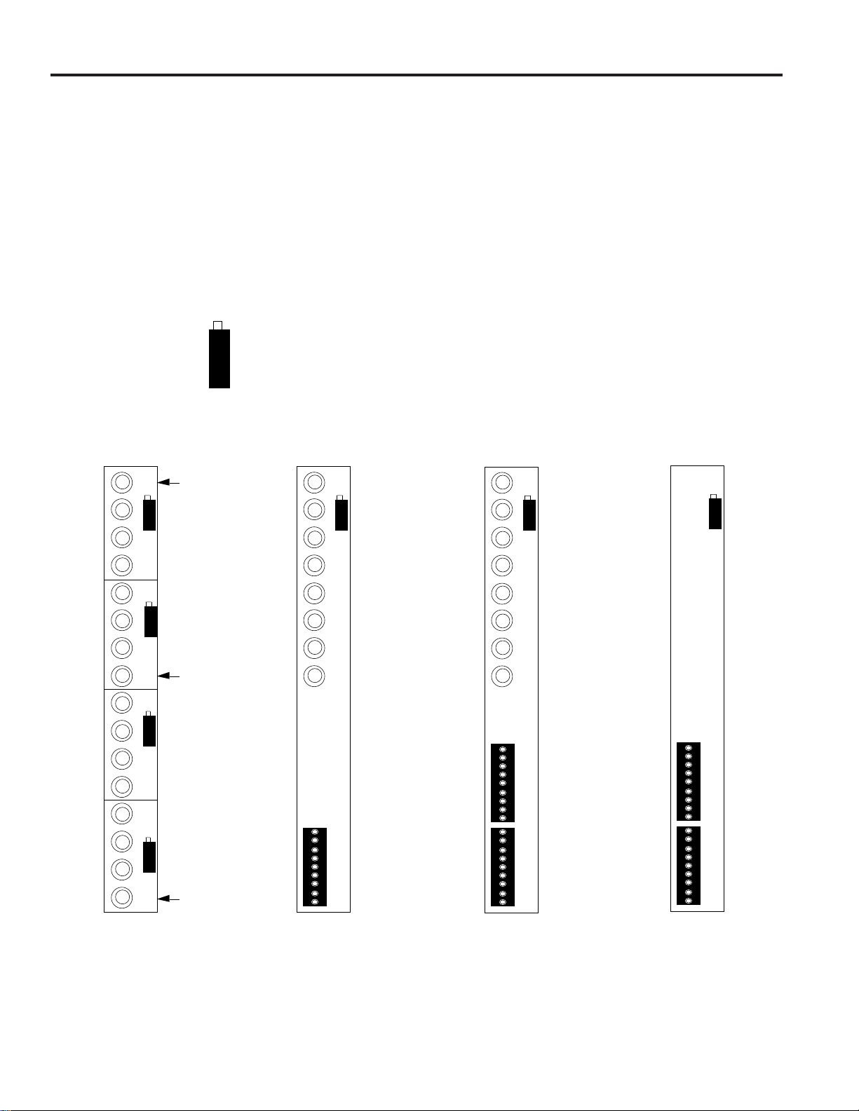
SETUP - Internal Jumper Switches
Data Buffer Module Switches
The 2010DB Data Buffer Module serves a dual purpose. First,
it sends video to the monitors and second, it filters incoming
information from the high speed LAN line.
Filtering is accomplished with two 8-position DIP switches, S2
and S3. Switch position 1 of switch S2 turns the filter "ON" or
"OFF." If S2 is set to"ON", all information passes and S3 does
not have to be set. If S2 is set to "OFF", only specified
information passes and S3 must be set. The S3 switch allows
only the necessary information to pass for that particular bay.
In the Condensed Bay configuration, or when a bay
contains 2024VOM monitor modules, the filter is set such
that all information passes. Therefore, position 1 of switch
S2 is set to ON.
For all other configurations the filter is set such that
information is filtered, thus position 1 of switch S2 is set to
OFF and S3 must be set accordingly. This applies to bays
which contain only 2016 VIM camera modules.
The Data Buffer Module also has a 2-position slide switch, S1.
S1 switches the card into either a normal mode or test mode.
S1 should be kept at the normal position.
Figure 25 shows the location of these switches on the 2010DB
PCB card.
Table 1 - S2 and S3 switch settings
1=On; 0=Off; X=Don't care
Switch S2
Filter 1 2 3 4 5 6 7 8
Pass all information (S2 ON) 1 0XXXXXX
Pass only specified information (S2 OFF) 0 0XXXXXX
Note: S2 must be set to pass all information (ON) in
bays which contain 2024VOM monitor modules.
Switch S3
Camera Monitor 1 2 3 4 5 6 7 8
1-256 1-16 X X 0 0 X 0 0 X
257-512 1-16 X X 1 0 X 0 0 X
513-768 1-16 X X 0 1 X 0 0 X
769-1024 1-16 X X 1 1 X 0 0 X
1-256 17-32 X X 0 0 X 1 0 X
257-512 17-32 X X 1 0 X 1 0 X
513-768 17-32 X X 0 1 X 1 0 X
769-1024 17-32 X X 1 1 X 1 0 X
1-256 33-48 X X 0 0 X 0 1 X
257-512 33-48 X X 1 0 X 0 1 X
513-768 33-48 X X 0 1 X 0 1 X
769-1024 33-48 X X 1 1 X 0 1 X
1-256 49-64 X X 0 0 X 1 1 X
257-512 49-64 X X 1 0 X 1 1 X
513-768 49-64 X X 0 1 X 1 1 X
769-1024 49-64 X X 1 1 X 1 1 X
12
CAUTION - Due to the presence of non-insulated
components with hazardous voltages, the
following internal adjustments should be
performed by qualified service personnel only.
1
8
1
8
S3
S2
S1
Figure 25 - Data Buffer Card Switches
SETUP
Video Loss Detector Data Buffer Module Switches
The 2010DBVL (Video Loss Detector Data Buffer Module) is
similar to the 2010DB, with the added capability of video loss
detection for each camera of the bay. A video loss detection
message is transmitted via the RJ45 port on the 2010DBVL
rear panel. An Alarm Contact is also provided from this port
(see connector pinouts, page 7).
The 2010DBVL is configured with a 2-position slide switch,
S1, and three 8-position DIP switches: S2, S3, and S4. S1 is
set for normal/test mode, as described for the 2010DB module.
DIP switch S2 sets the filtering mode, as described for the
2010DB, the Alarm Contact mode, and the RJ45 port baud
rate. Switch position 2 of S2 must be set to ON for the module
to function as a Video Loss Detection module.
The Alarm Contact modes are:
Alarm during Video or Sync Loss - The Alarm Contact is
closed and the ALARM LED on the 2010DBVL front
panel is illuminated when a sync or video loss is first
detected; both remain on until the loss is cleared.
Alarm during loss, plus 10 seconds - The Alarm Contact is
closed and the ALARM LED is illuminated as above, but
both remain on for 10 seconds after the loss is cleared.
Alarm at loss for 10 seconds - The Alarm Contact is closed
and the ALARM LED is illuminated as above, but both
remain on for only 10 seconds.
Alarm at loss for 20 seconds - The Alarm Contact is closed
and the ALARM LED is illuminated as above, but both
remain on for only 20 seconds.
The baud rate setting of DIP switch S2 configures the RJ45
port on the 2010DBVL for the desired communications rate.
DIP switch S3 must be set to the camera and monitor group
numbers assigned to the switching bay modules.
DIP switch S4 sets the type of communication used via the
RJ45 port and enables or disables the 2010DBVL front panel
LED's. This port may be configured for RS-232, RS-422, or
RS-485 communications.
The following tables show the switch position settings for DIP
switches S2, S3, and S4. Figure 26 shows the location of these
DIP switches on the 2010DBVL PCB card.
Table 2 - S2, S3, and S4 switch settings
1=On; 0=Off; X=Don't care
DIP Switch S2
Function 2 3 6
Video Loss Enabled 1 X X
Video Loss Disabled 0 X X
1
Pass all information 1
Pass only specified information 0
4 5
Alarm during Video or Sync loss 0 0
Alarm during loss, plus 10 seconds 1 0
Alarm at loss for 10 seconds 0 1
Alarm at loss for 20 seconds 1 1
7 8
1200 Baud Rate 0 0
2400 Baud Rate 1 0
4800 Baud Rate 0 1
9600 Baud Rate 1 1
DIP Switch S3
Camera Monitor 1 2 3 4 5 6 7 8
1-256 1-16 X X 0 0 X 0 0 X
257-512 1-16 X X 1 0 X 0 0 X
513-768 1-16 X X 0 1 X 0 0 X
769-1024 1-16 X X 1 1 X 0 0 X
1-256 17-32 X X 0 0 X 1 0 X
257-512 17-32 X X 1 0 X 1 0 X
513-768 17-32 X X 0 1 X 1 0 X
769-1024 17-32 X X 1 1 X 1 0 X
1-256 33-48 X X 0 0 X 0 1 X
257-512 33-48 X X 1 0 X 0 1 X
513-768 33-48 X X 0 1 X 0 1 X
769-1024 33-48 X X 1 1 X 0 1 X
1-256 49-64 X X 0 0 X 1 1 X
257-512 49-64 X X 1 0 X 1 1 X
513-768 49-64 X X 0 1 X 1 1 X
769-1024 49-64 X X 1 1 X 1 1 X
DIP Switch S4
Function 1 2 3 4 5 6 7
RS-232 1 1 0 0 0 0 0
RS-422 0 0 1 1 0 0 0
RS-485 0 0 1 1 1 1 0
8
Front Panel LED's ON 1
Front Panel LED's OFF 0
13
1
8
1
8
S3
S2
1
8
S4
S1
Figure 26 - DBVL Data Buffer Card Switches
SETUP
Video Input Module Switches
The 2016AVIM (Video Input Module) performs the actual
video switch. Each module can switch any one of 16 video
inputs to any video output, or multiple combinations of video
outputs, up to 16.
The 2016A Video Input Module must be set to the cameras and
monitors it is to respond to. There are two 8-position dip
switches. DIP switch S1 is used to set all field configurations.
The eight position dip switch S1, located on the circuit board,
must be set to identify the camera and monitor group. The first
two switches select one of four groups of 16 monitors and the
last six select one of 64 groups of 16 cameras. Switch settings
are shown in Table 3.
The monitor group selection is independent of the camera
group selection. Yet both monitor and camera group must be
selected correctly depending on the particular slot the card is
being placed in. Note: The silkscreen on the board clearly
shows the correct dip switch to use. The word "CAM GRP" is
screened adjacent to the correct dip switch.
The DIP switch S3 is not used in this module.
Table 3 - S1 Camera and Monitor Identification
1=On; 0=Off; X=Don't care
Switch Positions
Monitors 1 2 3 4 5 6 7 8
1- 16 0 0 XXXXXX
17- 32 0 1 XXXXXX
33- 48 1 0 XXXXXX
49 - 64 1 1 XXXXXX
65- 80 0 0 XXXXXX
81- 96 0 1 XXXXXX
97 - 112 1 0 XXXXXX
113 - 128 1 1 XXXXXX
Camera
1-16 X X 000000
17-32 X X 000001
33-48 X X 000010
49-64 X X 000011
65-80 X X 000100
81-96 X X 000101
97-112 X X 000110
113-128 X X 000111
129-144 X X 001000
145-160 X X 001001
161-176 X X 001010
177-192 X X 001011
14
81
S3
S1
Figure 27 - Video Input Module Card Jumper Switches

Table 3 - S1 Camera and Monitor Identification
(continued)
Switch Positions
Camera 1 2 3 4 5 6 7 8
193-208 X X 001100
209-224 X X 001101
225-240 X X 001110
241-256 X X 001111
257-272 X X 010000
273-288 X X 010001
289-304 X X 010010
305-320 X X 010011
321-336 X X 010100
337-352 X X 010101
353-368 X X 010110
369-384 X X 010111
385-400 X X 011000
401-416 X X 011001
417-432 X X 011010
433-448 X X 011011
449-464 X X 011100
465-480 X X 011101
481-496 X X 011110
497-512 X X 011111
513-528 X X 100000
529-544 X X 100001
545-560 X X 100010
561-576 X X 100011
577-592 X X 100100
593-608 X X 100101
609-624 X X 100110
625-640 X X 100111
641-656 X X 101000
657-672 X X 101001
673-688 X X 101010
689-704 X X 101011
705-720 X X 101100
721-736 X X 101101
737-752 X X 101110
753-768 X X 101111
769-784 X X 110000
785-800 X X 110001
801-816 X X 110010
817-832 X X 110011
833-848 X X 110100
849-864 X X 110101
865-880 X X 110110
881-896 X X 110111
897-912 X X 111000
913-928 X X 111001
929-944 X X 111010
945-960 X X 111011
961-976 X X 111100
977-992 X X 111101
993-1008 X X 111110
1009-1024 X X 111111
15
SETUP
SETUP
Video Output Module Switches
The 2024VOM (Video Output Module) adds character
information in the form of titles and time and date to switched
video from 2016AVIM modules. Each 2024VOM card
contains 2-pin jumpers and one 8-position DIP switch (see
Figure 28). These are set with the module removed from the
bay.
Four 2-pin jumpers for setting monitor identification are set at
the back of the card (end with gold-plated connections). Each
card can be set for monitors:
one, two, three, and four; or
five, six, seven, and eight; or
nine, ten, eleven, and twelve; or
thirteen, fourteen, fifteen, and sixteen.
There is no other variations, only the four types described
above.
Note: The silkscreen labeling on the VOM board shows which
jumper is for which monitor; these are labeled M1 through
M16. When setting monitors over sixteen, subtract multiples
of sixteen from the monitor number you want to set. For
example, to set monitors 33-36, subtract 32 to obtain monitors
one through four (33-32=1; 35-32=3, etc).
For selection of video type (Phase Adjusted Line, PAL or
National Television Systems Committee, NTSC), locate the
2-position jumper terminal near the center edge of the card.
Position the plastic 2-pin jumper to the appropriate location.
For selection of bay configuration (Standard or Condensed),
locate the 2-position jumper terminal near the center of the two
gold connectors. All bays are configured with the jumper
position set to "standard bay". In Condensed Bays, the jumper
is set to "standard bay" for cards corresponding to monitors 17
to 32, while the jumper is set to "condensed (or split) bay" for
cards corresponding to monitors 1 to 16.
Note: The bay configuration switch was implemented on Rev
"B" boards. Before Rev "B" boards, resistors were placed on
the solder side of the board (Condensed Bays only).
The 8-position DIP switch S2, located on the circuit board,
must be set to identify the video inputs and outputs the module
must respond to. Switch settings are dependent on the slot
location in the matrix bay as well as which matrix bay the card
is located. Switch settings are shown in Tables 4a, 4b, and 5.
Table 4 represents the first four switches of S2, which
identifies video input. If the video output is located in a matrix
switching bay that includes video input cards its video input
would be considered internal. If the video output card is
located in a matrix switching bay which contained only output
cards its video inputs would be considered external.
Table 5, on page 17, identifies which video outputs the card
will be controlling.
Table 4a - S2 Internal Video Input Identification
1=On 0=Off
Switch Positions
Video Inputs 1 2 3 4
1 to 256 0000
257 to 512 1000
513 to 768 0100
769 to 1024 0010
Table 4b - S2 External Video Input Identification
1=On 0=Off
Switch Positions
Video Inputs 1 2 3 4
1 to 256 1000
257 to 512 0100
513 to 768 0010
769 to 1024 0001
Note: Table 4a is used when the 2024VOM is located in a
matrix switching bay which includes 2016AVIM. Table 4b is
used when the 2024VOM is located in a matrix switching bay
which does not include 2016AVIM modules. In both
instances, the Filter DIP switch S2 on the 2010DB/2010DBVL
Data Buffer Module must be set to pass all data (see page 12).
DIP Switch S1 and slide Switch S3 are not used on the
2024VOM card.
NTSC/PAL
jumper
Condensed or
Standard Bay
Monitors 1 - 4
Monitors 5 - 8
Monitors 9 -12
Monitors 13-16
1
8
1
8
S2
S1
16
Figure 28 - VOM Card Jumper Switches
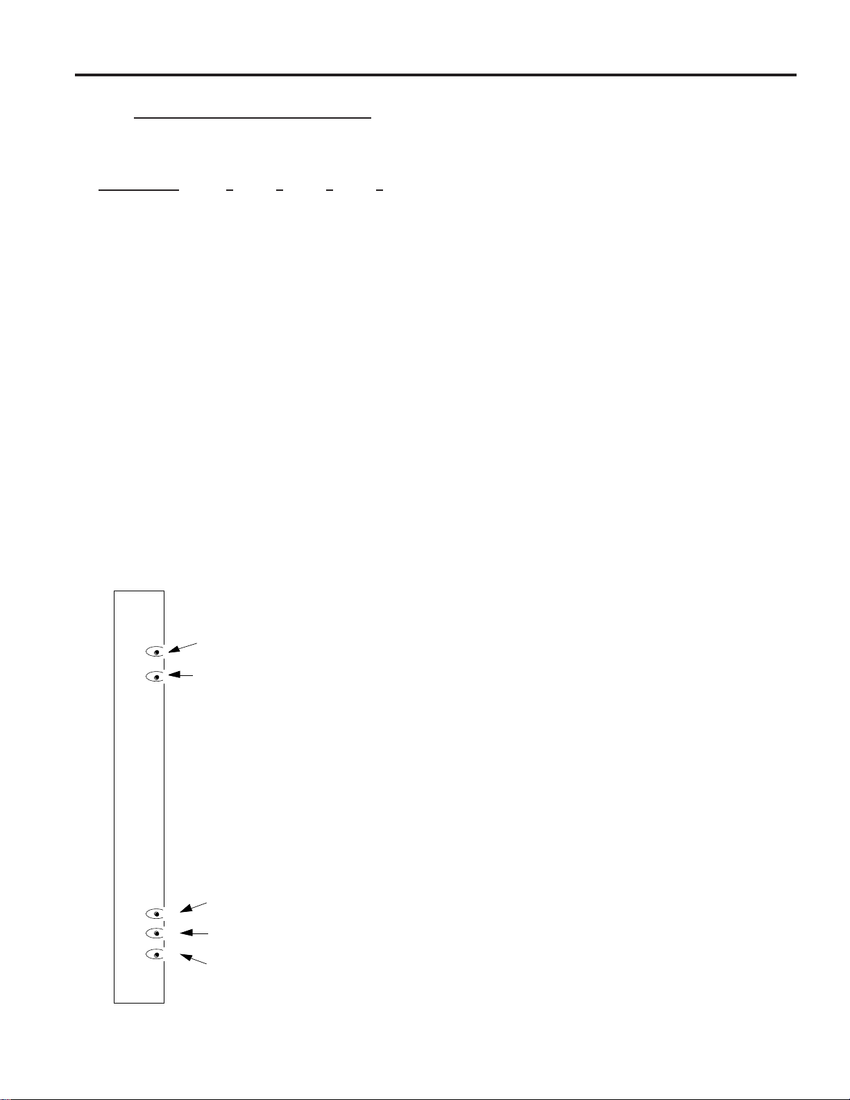
Table 5 - S2 Video Output Identification
1=On 0=Off
Switch Positions
Video Output 5 6 7 8
1 to 4 0000
5 to 8 1000
9 to 12 0100
13 to 16 1100
17 to 20 0010
21 to 24 1010
25 to 28 0110
29 to 32 1110
33 to 36 0001
37 to 40 1001
41 to 44 0101
45 to 48 1101
49 to 52 0011
53 to 56 1011
57 to 60 0111
61 to 64 1111
Video Output Module - Horizontal, Vertical, and
Brightness Adjustment
The 2024VOM has four video outputs each with title
information displayed on the video picture. The title
information on the screen is adjustable for horizontal and
vertical position. The brightness of the characters is also
adjustable. The rotary switch located on the front panel of
each output module selects which output will be adjusted. The
''H", ''V" and ''B" pushbuttons are used to adjust the desired
setting. See Figure 29 for location of these controls.
The video output title to be controlled is selected from the
rotary switch labeled ''A . . D". To select the first video output,
turn the rotary switch to position ''A". To select the second
video output for title adjustment, move the rotary switch
clockwise one position. Proceed in this manner for the final
two video outputs.
After selecting one of the four outputs, press the ''H"
pushbutton. The title shifts to the right until the pushbutton is
released.
Note: If the pushbutton is not released, the title will reach an
end point and return to the left-most position and begin to shift
to the right again.
After the proper horizontal position has been selected, depress
the ''V" pushbutton. The title will shift downward until the
pushbutton is released. Note: If the pushbutton is not
released, the title will reach the bottom of the screen, as
defined by the vertical sync, move to the top of the screen, and
begin to shift down again.
After the proper horizontal and vertical positions have been
selected, proceed to the brightness control. The characters of
the title are white with a black border. This enhances visibility
under varying light conditions. The brightness control
provides eight steps of white levels to change the characters
from white to black. To change the brightness of the titles,
depress the ''B" pushbutton. The title steps through each level
until the pushbutton is released.
The video output rotary switch may be placed to any position
when title adjustment is completed.
17
SETUP
H
V
B
A
D
.
.
Blinking LED for proper operation
4-position rotary switch
Horizontal control push button
Vertical control push button
Brightness control push button
Figure 29 - Video Output Module Front Panel
Power Supply Set Up - Vertical Phase Adjustment
The matrix switching bays are designed as vertical interval
switches, thus giving the matrix switching bay the ability to
switch between properly phased video inputs without
producing a vertical roll, or a black bar, between each video
switch. Use of this feature allows vertical interval switching to
be controlled by the AC Line (Line Locked ), External Vertical
Drive (Generator Locked), or Composite video input.
1. AC LINE: The most common form of synchronization is
AC line lock of the vertical switching point. To use this
feature, switch the Sync Reference Selection switch to AC
LINE (see Figure 1 on page 2). This will use the AC (either 60
or 50 Hz) line to determine the vertical timing. If all video
inputs use the same phase of AC power to determine the
vertical timing, no roll will appear.
As an aid to the installer, a switch on the Power Supply
Module is available to check the vertical switch location for
each video input. This function is initiated when the SET
UP/NORMAL switch is selected to the SET UP position.
A. Connect a monitor to the top most BNC of the 2010DB-00
labeled Test/Expansion Only, or the first monitor output of
any level VOM. If the monitor card is present, connect to
the video output module monitor 1. If not, use the Data
Buffer output #1.
B. From an external keyboard call input 1 to output 1.
C. Place the SET UP/NORMAL switch to the SET UP
position. This implements the phase adjustment procedure.
Note: The Sync Test On/Off LED will be blinking when
the sync test switch is in the SETUP position.
Notice that the alignment bar, displayed on output 1, shows the
location of the vertical switch with respect to the picture.
D. The phase adjustment potentiometer, accessed thru the hole
in the front panel of the Power Supply, adjusts the phase of
the vertical interval synchronization pulse for the switcher
with respect to the selected reference.
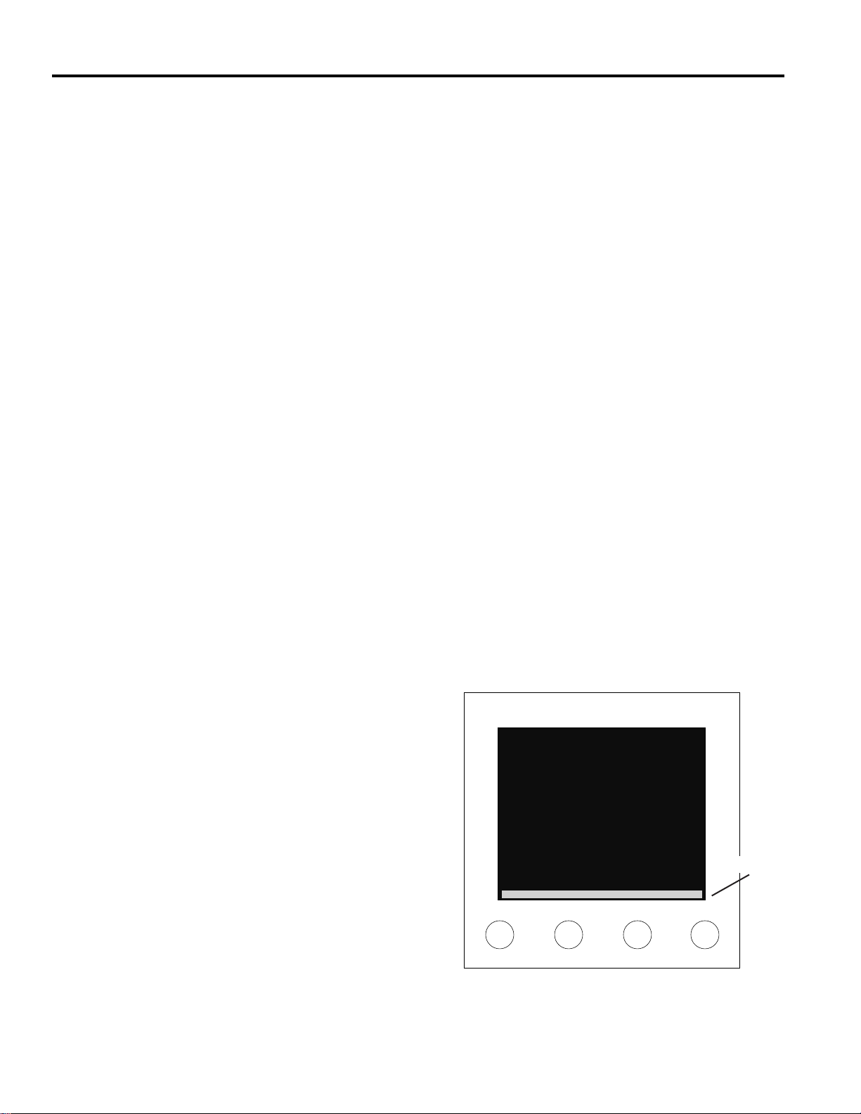
E. Adjust the position of the bar with a TV alignment tool, or
equivalent, by turning the phase potentiometer, until the
line is located as seen in Figure 30. The line should be
visible on the screen.
Once the alignment bar is set, no further adjustment to the
potentiometer is necessary.
F. Select the second video input in the system. If the
horizontal bar is not in the same location as seen in Figure
30, adjust the sync location on the "video device" (i.e.,
video camera) until the horizontal bar is located towards
the bottom of the screen. If this is not possible, and the
alignment bar is located in a different position than it was
in the previous camera, you will experience camera roll
during switching operations to that camera.
G. Repeat this for all video inputs to the system.
Note: Before adjusting all of the video inputs, quickly scan
all inputs to see if only a few are out of phase and adjust
accordingly (input one may be the only oddball!).
H. Once all cameras have been synchronized, place the SET
UP/NORMAL switch to the NORMAL position.
If multiple matrix switching bays are used, repeat steps A - H
for each bay. The sync/test output for these bays is the top
most output BNC located on each 2010DB-XX rear panel at
the first monitor of the bay, i.e., monitor 17-32, etc.
2. EXT V-DRIVE: If an external generator is used to control
the vertical switching point, switch the Sync Reference
Selection switch to EXT V-DRIVE (external vertical drive).
For proper operation, the output voltage of the generator
should not exceed 5V peak-to-peak (p-p). Connect the drive
output from the generator to the EXT SYNC IN BNC located
on the 2010PS rear panel. Connect a 75-ohm terminator to the
EXT SYNC OUT BNC. If other bays are used, loop the EXT
SYNC from input to output for all bays and terminate the last
bay EXT SYNC OUT BNC in 75-ohms.
3. EXT CAM: If composite video is used to control the
vertical switching point, switch the Sync Reference Selection
switch to EXT CAM (external camera). For proper operation,
the composite sync signal is specified at 1.1V p-p. Connect
the composite sync to the EXT SYNC IN BNC located on the
2010PS rear panel. Connect a 75-ohm terminator to the EXT
SYNC OUT BNC. If other bays are used, loop the EXT
SYNC from input to output for all bays and terminate the last
bay EXT SYNC OUT BNC in 75-ohms.
18
Figure 30 - Placement of Setup Alignment Bar
Alignment bar should be visible on the monitor and not in the
vertical sync.
alignment bar
Monitor 1
SETUP

POWERING UP
The system may be brought on line after:
- The CPU has been installed and connected.
- A video input has been connected.
- A monitor has been connected for viewing the output.
- All lines have been properly terminated.
- One keyboard (or external computer) has been connected for
control.
- Power has been connected to the equipment, one bay at a
time, ending with the CPU.
Powering the Matrix Bay
1. Unscrew the two thumbscrews located at the top corners of
front panel of each matrix switching bay.
2. Remove the front panel by first slowly pulling the top of the
panel towards the front, then lifting the panel up.
Note: DO NOT remove the foam material attached to the
front panel.
3. Verify that the unit is turned off. The unit is turned off by
pressing the bottom of the front panel power On/Off switch.
4. Power is supplied via a pendant cord and plug. Connect the
pendant cord to the required voltage input:
AD1024R 120VAC, 50/60 Hz
ADS1024RX 230VAC, 50/60 Hz
5. To turn the unit on, press the top of the front panel power
On/Off switch.
Replace the front panel only after all setup adjustments have
been made related to powering up instructions (Power Supply
Module and Video Output Module, prior pages).
6. To replace the front panel, slip the bottom of the panel into
the slot at the bottom of the bay. Push the top of the panel
towards the bay and tighten the two corner thumb screws.
POWER UP
19

SYSTEM CONFIGURATIONS
SYSTEM CONFIGURATIONS
The following sections of this manual are organized specific to
the system level to be installed. A level is defined as 16 video
outputs, and may consist of one to several bays. Level 1 is for
a maximum of 16 outputs, Level 2 is for 32 outputs, and so on
up to Level 8 which is for a maximum of 128 outputs.
System bays are supplied in the following two configurations:
Standard (Model 2010R) and Condensed (Model 2020R).
References to "Right" or "Left" in the following
instructions apply to the Bays as viewed from the REAR.
LEVEL 1 SYSTEMS
Level 1 systems can have a maximum of five 2010R Standard
matrix switching bays that each contain the 2010PS Power
Supply Module and a 2010DB or 2010DBVL Data Buffer
Module. Level 1 Systems can consist of a maximum of
AD1024 video inputs and a maximum of 16 video outputs (15
outputs if the 2010DBVL module is used).
For a Level 1 system with Video Loss Detection capability, the
video output for monitor 16 is replaced by the Video Loss
Detection function in the 2010DBVL Module. Since each
2010DBVL can detect video losses for a maximum of 256
cameras, an additional 2010DBVL Module is required in each
camera bay, for each block of 256 cameras. The first camera
bay would use a 2010DBVL-11, the second bay a 2010DBVL-
21, the third bay a 2010DBVL-31 and the fourth bay a
2010DBVL-41. In a multi-bay system where the last bay
contains both camera modules and monitor modules, that bay
would use a 2010DBVL-00 module. In a five-bay system, the
fifth bay is exclusively a monitor bay and would require the
2010DB-00 Module, not the 2010DBVL-00.
LEVEL 1 - 256 X 16, One Bay System with no Titles
A one bay, Level 1 system, without VOM modules for video
titles, allows a maximum of 256 video inputs switched to a
maximum of 16 video outputs.
This system does not contain 2024VOM modules.
From the rear of the bay, the modules are installed at the
factory in the following manner; the far right module is the
2010PS; the next module is the 2010DB-01 with 16 BNCs for
untitled video outputs, followed by one to sixteen 2016AVIM-
1 modules. Smaller matrices, such as those ordered with future
expansion in mind, may have fewer modules installed.
IDENTIFY THESE MODULES CAREFULLY
BEFORE PROCEEDING.
Data Interconnect: Connect a 75-ohm coaxial cable from the
DATA LINE-1 output on the AD1024 CPU, to the Data IN
BNC on the 2010PS rear panel. Connect a 75-ohm BNC
terminator (supplied with the CPU) to the Data Out BNC on
Power Supply rear panel.
Video Input Connections: The 2016AVIM is identified with
the camera input icon .
The starting camera
number, for the particular
VIM, is located at the top
BNC. Each 2016AVIM-1 includes 16 terminated BNCs for
video input connections. The first 2016AVIM-1, located
immediately to the left of the 2010DB-01, is for video inputs 1
- 16, the second 2016AVIM-1 module is for inputs 17 - 32, etc.
In succession, connect the video inputs to each 2016AVIM-1
module, top to bottom. Each VIM will accept 16 video inputs.
Continue until all inputs are connected to the system. Unused
video inputs, on the VIM, do not require any external
connection or termination, and may be left open. See Figure
16, Video Input Module, page 8.
Video Output Connections with No Titles: Each 2010DB-01
in the system has 16 BNCs. The top most BNC corresponds to
video output 1 and the bottom video output corresponds to
number 16. Connect the video outputs to any device that
accepts standard video such as monitors or video recorders.
See Figure 4, 2010DB-01 Rear Panel with 16 BNCs, page 4.
In the Appendix, see Figure A1, 256 X 16, One Bay System
with No Titles.
20

LEVEL 1 - 256 X 15, One Bay System with Video Loss
Detection
A one bay, Level 1 system, with video loss detection and
without video titles, allows a maximum of 256 video inputs
switched to a maximum of 15 video outputs.
This system is the same configuration of modules as the
LEVEL 1 - 256 X 16 system except that the 2010DBVL-01
Video Loss Detection Data Buffer module is installed in place
of the 2010DB-01 module. The connections are as described
for that system configuration, except that only 15 BNCs are
provided for video outputs.
See Appendix Figure A18, 256 X 15, One Bay System with
Video Loss Detection Module.
LEVEL 1 - 192 X 16, One Bay System
A one bay, Level 1 system, with 2024VOM modules for video
titles, allows a maximum of 192 video inputs switched to a
maximum of 16 video outputs.
From the rear of the bay, the modules are installed at the
factory in the following manner; the far right module is the
2010PS; the next module is the 2010DB-00, followed by
twelve 2016AVIM-1 modules, and four 2024VOM-1 modules.
Smaller matrices, such as those ordered with future expansion
in mind, may have fewer modules installed.
IDENTIFY THESE MODULES CAREFULLY
BEFORE PROCEEDING.
Data Interconnect: Connect a 75-ohm coaxial cable from the
DATALINE-1 output on the AD1024 CPU to the DATA IN
BNC on the 2010PS rear panel. Connect a 75-ohm BNC
terminator (supplied with the CPU) to the Data Out BNC on
the Power Supply rear panel.
Video Input Connections: The 2016AVIM is identified with
the video input icon.
The starting video input number, for the particular VIM, is
located at the top BNC. Each 2016AVIM-1 includes 16
terminated BNCs for video input connections. The first
2016AVIM-1, located immediately to the left of the 2010DB-
00, is for video inputs 1-16, the second 2016AVIM-1 module is
for inputs 17- 32, etc.
In succession, connect the video inputs to each 2016AVIM-1
module, top to bottom. Each VIM will accept 16 video inputs.
Continue until all inputs are connected to the system. Unused
video inputs, on the VIM, do not require any external
connection or termination, and may be left open. See Figure
16, Video Input Module, page 8.
Video Output Connections: Each 2024VOM-1 has a rear
panel with 16 BNCs. For single bay systems, only the bottom
four BNCs are used for video output connections. The left
most module is assigned to outputs 1 - 4. Moving left to right,
the next VOM module is assigned to outputs 5 - 8, etc. (The
modules are numbered 1 - 4, 5 - 8, etc.) Connect the video
outputs to any device that accepts standard video such as
monitors or video recorders. See Figure 21, Video Output
Module, page 9.
In the Appendix, see Figure A2, 192 X 16, One Bay System.
SYSTEM CONFIGURATIONS
21
Loading...