


ADACSNET
USB Control Module
The following diagram shows how to install the control module between the host (Intellex or PC) and a camera.
Host (Intellex shown)
Installation Guide
2-Pin SensorNet
Termination Connection
Switch
Communication LEDs |
USB Port |
|
The USB Control Module allows a host computer, such as an Intellex digital video management system (or a PC with a USB port), to control one or more American Dynamics camera domes using the SensorNet (RS-485) communication protocol.
This guide explains:
•Features of the module and basic hookup
•Information required to download software, if required
•SensorNet Rules and network types.
Features and Hookup
The USB Control Module contains the following:
•USB port: Connects to the host computer.
•Communication LEDs: A yellow LED indicates correct USB connection by glowing steadily or blinking. Immediately after power is turned on, a green LED glows steadily for about 3 seconds then turns off. This LED also blinks every time a data packet is sent to the camera dome.
•Termination switch: Termination is indicated by a resistor symbol near the switch. See
SensorNet Rules and Network Types in this document for when to set the switch.
© 2007 Sensormatic Electronics Corp.
|
Control |
|
To J-Boxes or |
USB Port |
Module |
|
Camera Domes |
|
|
SensorNet |
|
|
|
|
|
|
|
Connection |
|
Software Installation for
Intellex Driver
Note: This procedure only applies to Intellex 3.x and 4.x systems.
1.Exit Intellex by selecting Utility > Exit. You will see the message: Do you wish to quit the program?
2.Click Yes, and enter pin code 98374252.
3.Once in the Windows desktop, plug in your USB control module. The Found New Hardware Wizard screen appears.
4.Click Next. A Search for Suitable driver screen appears.
5.Select the Search for a suitable driver for my device (recommended) box and then click Next.
6.From the Locate Driver Files screen, click the
Specify a location check box, and click Next.
7.Do one of the following:
•For Intellex DVMS, IP, and rack-mount LT, browse to the
C:\drivers\USB Dome Control folder.
•For Intellex Ultra 4.0, browse to the
E:\drivers\USB Dome Control folder.
8.Press Open, and then OK.
ADACSNET USB CONTROL MODULE |
8200-0310-01, REV. C |
INSTALLATION GUIDE |
1 of 6 |
Software Installation for NonIntellex Systems
Note: This procedure applies to systems using Microsoft® Windows® 2000 or Windows® XP operating systems.
If you are not connecting the ADACSNET module to an Intellex system, special drivers and utilities software must be downloaded to your personal computer that enable its use.
USB Control Module Software Utilities User Guide, 8200-0310-02, explains how to download this software. To obtain this guide:
1.On the internet, go to http://americandynamics.net/home/default.aspx, and click Support.
2.In the dropdown menu, click Support Documents, and then click Manual Index.
3.Click SpeedDomes and Accessories, and then scroll down and click USB Control Module Software Utilities User Guide.
4.Follow the instructions on the screen to download the user guide PDF file.
SensorNet Rules and
Network Types
The SensorNet communication protocol allows the host computer and camera domes to exchange data along a cable network (star, daisy chain, or backbone).
SensorNet Rules
•A star network cannot have more than four branches, one line termination per branch.
•A backbone network has a termination at each end of the line.
•A SensorNet line cannot have more than 32 network-compatible devices.
•A network cannot have more than four repeaters in the path of any two camera domes.
•A SensorNet line or branch cannot exceed 1km (3300ft). Use signal repeaters only when exceeding the maximum distance or noise is an issue.
•Signal levels for SensorNet-compatible devices are from 0.3–5V (1–5V is recommended).
Network Types
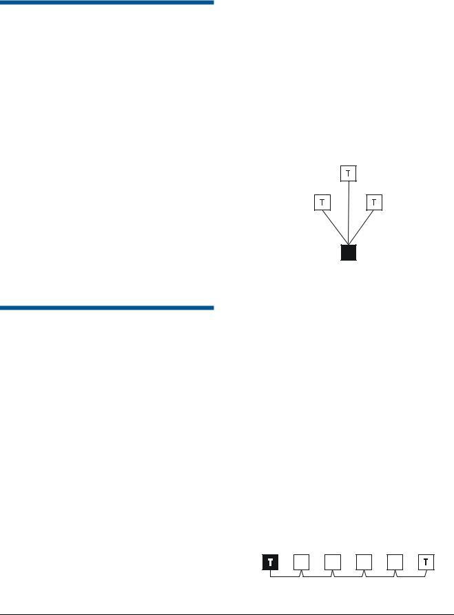
Star Network
The star network allows you to relocate devices. However, this network is not recommended in high noise environments because the extra terminations required will lower the signal to noise ratio.
A separate cable line (branch) runs from the USB module to each device. Limit the branches to four.
The example below shows the USB module as the hub of a star network. The module is not terminated.
Black box = USB module, T = Terminated
Not
Terminated
Daisy-Chain/Backbone Network
Use a daisy chain network if the cable is to be short, extended in the future, or when USB module and camera domes are in the same room. In a daisy chain, a separate cable connects every two adjacent devices along the chain. Daisy chaining makes it easy to add devices by extending the network from a nearby device. The USB module can connect anywhere along the cable.
Use a backbone network if the cable is to be long and permanent. This network type operates the same as the daisy chain, but uncut wires may be more conductive and reliable. In a backbone, a single cable is used. Along the cable, 2.5cm (1in) sections are stripped, bent, and connected to each remote device. The USB module can connect anywhere along cable.
The example below shows the USB module at end of a daisy chain or backbone network. The module and the last camera dome in the chain are terminated.
Black box = USB module, T = Terminated
ADACSNET USB CONTROL MODULE INSTALLATION GUIDE
8200-0310-01, REV. C
2 of 6
 Loading...